EP3549896A1 - Resetting device for resetting an actuator for actuating a safety gear of an elevator - Google Patents
Resetting device for resetting an actuator for actuating a safety gear of an elevator Download PDFInfo
- Publication number
- EP3549896A1 EP3549896A1 EP18166112.5A EP18166112A EP3549896A1 EP 3549896 A1 EP3549896 A1 EP 3549896A1 EP 18166112 A EP18166112 A EP 18166112A EP 3549896 A1 EP3549896 A1 EP 3549896A1
- Authority
- EP
- European Patent Office
- Prior art keywords
- brake
- electric motor
- gear
- actuation
- resetting
- Prior art date
- Legal status (The legal status is an assumption and is not a legal conclusion. Google has not performed a legal analysis and makes no representation as to the accuracy of the status listed.)
- Withdrawn
Links
- 230000005540 biological transmission Effects 0.000 claims abstract description 35
- 230000005611 electricity Effects 0.000 claims description 6
- 230000006835 compression Effects 0.000 description 9
- 238000007906 compression Methods 0.000 description 9
- 230000004913 activation Effects 0.000 description 4
- 238000006073 displacement reaction Methods 0.000 description 3
- 238000005452 bending Methods 0.000 description 2
- 230000015556 catabolic process Effects 0.000 description 2
- 230000014759 maintenance of location Effects 0.000 description 1
Images




Classifications
-
- B—PERFORMING OPERATIONS; TRANSPORTING
- B66—HOISTING; LIFTING; HAULING
- B66B—ELEVATORS; ESCALATORS OR MOVING WALKWAYS
- B66B5/00—Applications of checking, fault-correcting, or safety devices in elevators
- B66B5/02—Applications of checking, fault-correcting, or safety devices in elevators responsive to abnormal operating conditions
- B66B5/16—Braking or catch devices operating between cars, cages, or skips and fixed guide elements or surfaces in hoistway or well
- B66B5/18—Braking or catch devices operating between cars, cages, or skips and fixed guide elements or surfaces in hoistway or well and applying frictional retarding forces
-
- B—PERFORMING OPERATIONS; TRANSPORTING
- B66—HOISTING; LIFTING; HAULING
- B66B—ELEVATORS; ESCALATORS OR MOVING WALKWAYS
- B66B1/00—Control systems of elevators in general
- B66B1/34—Details, e.g. call counting devices, data transmission from car to control system, devices giving information to the control system
-
- B—PERFORMING OPERATIONS; TRANSPORTING
- B66—HOISTING; LIFTING; HAULING
- B66B—ELEVATORS; ESCALATORS OR MOVING WALKWAYS
- B66B5/00—Applications of checking, fault-correcting, or safety devices in elevators
- B66B5/0087—Devices facilitating maintenance, repair or inspection tasks
-
- B—PERFORMING OPERATIONS; TRANSPORTING
- B66—HOISTING; LIFTING; HAULING
- B66B—ELEVATORS; ESCALATORS OR MOVING WALKWAYS
- B66B5/00—Applications of checking, fault-correcting, or safety devices in elevators
- B66B5/02—Applications of checking, fault-correcting, or safety devices in elevators responsive to abnormal operating conditions
- B66B5/04—Applications of checking, fault-correcting, or safety devices in elevators responsive to abnormal operating conditions for detecting excessive speed
- B66B5/044—Mechanical overspeed governors
-
- B—PERFORMING OPERATIONS; TRANSPORTING
- B66—HOISTING; LIFTING; HAULING
- B66B—ELEVATORS; ESCALATORS OR MOVING WALKWAYS
- B66B5/00—Applications of checking, fault-correcting, or safety devices in elevators
- B66B5/02—Applications of checking, fault-correcting, or safety devices in elevators responsive to abnormal operating conditions
- B66B5/16—Braking or catch devices operating between cars, cages, or skips and fixed guide elements or surfaces in hoistway or well
- B66B5/18—Braking or catch devices operating between cars, cages, or skips and fixed guide elements or surfaces in hoistway or well and applying frictional retarding forces
- B66B5/22—Braking or catch devices operating between cars, cages, or skips and fixed guide elements or surfaces in hoistway or well and applying frictional retarding forces by means of linearly-movable wedges
-
- F—MECHANICAL ENGINEERING; LIGHTING; HEATING; WEAPONS; BLASTING
- F16—ENGINEERING ELEMENTS AND UNITS; GENERAL MEASURES FOR PRODUCING AND MAINTAINING EFFECTIVE FUNCTIONING OF MACHINES OR INSTALLATIONS; THERMAL INSULATION IN GENERAL
- F16D—COUPLINGS FOR TRANSMITTING ROTATION; CLUTCHES; BRAKES
- F16D59/00—Self-acting brakes, e.g. coming into operation at a predetermined speed
- F16D59/02—Self-acting brakes, e.g. coming into operation at a predetermined speed spring-loaded and adapted to be released by mechanical, fluid, or electromagnetic means
-
- F—MECHANICAL ENGINEERING; LIGHTING; HEATING; WEAPONS; BLASTING
- F16—ENGINEERING ELEMENTS AND UNITS; GENERAL MEASURES FOR PRODUCING AND MAINTAINING EFFECTIVE FUNCTIONING OF MACHINES OR INSTALLATIONS; THERMAL INSULATION IN GENERAL
- F16D—COUPLINGS FOR TRANSMITTING ROTATION; CLUTCHES; BRAKES
- F16D2121/00—Type of actuator operation force
- F16D2121/18—Electric or magnetic
- F16D2121/20—Electric or magnetic using electromagnets
- F16D2121/22—Electric or magnetic using electromagnets for releasing a normally applied brake
Definitions
- the present invention relates to a resetting device for resetting an actuator for actuating a safety gear of an elevator.
- a conventional elevator comprises a safety gear mounted to the elevator car or to the counterweight (moving mass) and the safety gear is activated by an overspeed governor system when the speed of the moving mass exceeds a predetermined tripping or activation speed which is above a rated speed of the elevator.
- a ropeless overspeed governor system comprises an actuator having an actuation lever which acts on the safety gear and which is connected to a sychronization rod being urged by an actuation spring in a direction to actuate the safety gear via the actuation lever. In the un-activated state of the actuator, the actuation lever is held by a holding magnet against the urging force of the actuation spring.
- the actuation lever When the holding magnet is de-energized, the actuation lever is no longer held by the holding magnet such that the actuation spring will act to push the synchronization rod which in turn makes the actuation lever turn in a manner to activate the safety gear. As a result, the elevator is stopped by engagement between the safety gear and a guide rail mounted in the elevator shaft. When the elevator is brought into a state of being able to travel again, the actuator needs to be brought back into the un-activated state by means of a resetting device which involves compressing the actuation spring. Compared to an overspeed governor system tripped by a rope, in the ropeless overspeed governor system, the actuation spring needs to be stronger and thus a higher force is required to compress the actuation spring for resetting the actuator.
- Conventional resetting devices comprise a lever for compressing the actuation spring and the lever is moved by a linear motor.
- an actuation lever 33 is connected to a spring seat, a synchronization rod 40 and a resetting lever 43.
- a holding magnet 35 and a tiltable holding device 34 are mounted to the resetting lever 43.
- a spring 32 is compressed between the above-mentioned spring seat and another spring seat 31, and the holding device 34 is engaged with a catch 34a of the actuation lever 33 and is held by the holding magnet 35.
- the resetting lever 43 is further connected to a spindle drive having an electric motor 39.
- the holding magnet 35 is de-energized and releases the holding device 34 such that the movement of the actuation lever 33 is allowed and the spring 32 pushes the actuation lever 33.
- the electric motor 39 is operated so as to move the holding magnet 35 and the holding device 34 toward the catch 34a.
- the holding magnet is activated such that the catch 43a and the holding device 34 are engaged.
- the electric motor 39 is operated in the reverse direction so as to bring the actuation lever 34 back into the un-activated position against the compression force of the spring 32.
- the use of the spindle drive which is a linear actuator, has the disadvantage that the force levels during resetting the actuator is very high so that a support portion for supporting the linear actuator easily bends which causes unwanted stresses and displacements for the device. Furthermore, since these high force levels have to be provided by an electric motor, the electric motor needs to be large.
- an actuation spring is brought into the compressed state by driving an electric motor which provides a resetting force.
- a transmission means transmits the resetting force to the compression spring with a positive gear ratio.
- an interruption means can interrupt the transmission of forces between the electric motor and the actuation spring in a state in which the actuation spring is reset.
- a holding magnet for holding an actuation lever in an un-activated position, wherein the actuation lever is operatively connected to the safety gear is preferably fixed to the frame.
- the holding magnet reliably holds the actuation lever even when the transmission of forces between the electric motor and the actuation spring is interrupted.
- the holding magnet since the holding magnet is fixed to the frame and does not need to be held by the electric motor, it is possible to interrupt the transmission of forces between the actuation spring and the electric motor. This allows switching off the electric motor after resetting of the actuator is finished.
- the interruption means is preferably an electromagnetic clutch provided between the electric motor and the actuation lever.
- the electromagnetic clutch can be suitable mounted to the actuator and allows quick and reliable interruption of the transmission of forces between electric motor and actuation spring.
- the electromagnetic dutch is preferably disengaged when no electricity is supplied. Hence, even during power breakdown, the electric motor is decoupled from the actuator such that activation of the safety gear is not hindered by the electric motor.
- the double gear mechanism according to claim 7 allows providing a large gear ratio between the output shaft and the input shaft of the transmission means such that the electric motor can be designed to provide a small torque.
- the planetary gear set according to claim 8 allows providing a large gear ratio between the ring gear and the carrier such that the electric motor can be designed to provide a small torque.
- Forming the transmission means as a planetary gear set allows to have a robust and compact transmission means.
- the planetary gear set can be designed to provide a small gear ratio between the ring gear and the sun gear such that the counter torque acting on the sun gear, which is generated during operation of the electric motor when compressing the actuation spring and is a counter torque to the motor torque applied to the carrier[PH1], is small.
- the provision of the brake disc allows to brake this small torque of the sun gear with a small brake force in accordance with the diameter of the brake disc. As a result, the brake can be designed to be small which allows a cost efficient solution.
- the sun gear is connected to the electric motor.
- the planetary gear set according to claim 10 allows providing a large gear ratio between the carrier and the ring gear such that the electric motor can be designed to provide a small torque. Forming the transmission means as a planetary gear set allows to have a robust and compact transmission means.
- the carrier is connected to the brake disc.
- the interruption means in combination with the planetary gear set in a cost efficient manner.
- the planetary gear set can be designed to provide a small gear ratio between the ring gear and the sun gear such that the counter torque acting on the carrier, which is generated during operation of the electric motor when compressing the actuation spring and is a counter torque to the motor torque applied to the sun gear, is small.
- the provision of the brake disc allows to brake this small torque of the sun gear with a small brake force in accordance with the diameter of the brake disc. As a result, the brake can be designed to be small which allows a cost efficient solution.
- the brake is not operated when no electricity is supplied. Hence, even during power breakdown, the electric motor is decoupled from the actuator such that activation of the safety gear is not hindered by the electric motor.
- the planetary gear set according to claim 13 allows providing a large gear ratio between the output shaft and the input shaft of the transmission means such that the electric motor can be designed to provide a small torque.
- the brake wedge when the brake wedge is actuated by the actuation lever, the brake wedge moves along the counter wedge and the counter wedge moves along the guide surface. Due to the inclined lateral sides of the brake wedge and the counter wedge, the brake wedge is pressed laterally inward such that the brake wedge acts on the elevator guide rail to generated a braking force.
- the brake wedge comprises a friction surface which acts of the elevator guide rail so as to generated the braking force.
- the brake wedge when the brake wedge is activated by the actuation lever, the counter wedge is pressed against the counter spring. As a result, the counter wedge is moved to a smaller amount than the brake wedge which contributes to that the brake wedge is pressed laterally inward against the elevator guide rail such that the brake force is reliably generated. Furthermore, when the actuation of the safety gear is released after the stop of the elevator car, the compression spring applies a pressing force to the counter wedge so that the counter wedge is pressed back into its initial position. As a result, the brake wedge can reliably be released from the elevator guide rail such that the safety gear is reliably released.
- Figs. 1A , 1B and 2 show an actuator having a resetting device 1 according to a first embodiment the invention.
- the actuator comprises a frame 6 which is provided on the bottom of an elevator car (not shown) or a counterweight (not shown).
- the frame 6 comprises two adjacent beams 6a, 6b which are mounted to the elevator car/counterweight at their upper sides, and which are connected to safety gears 14l, 14r on their lower sides on both longitudinal ends of the frame 6.
- the safety gears 14l, 14r are configured to engage with a guide rail (not shown) provided in an elevator shaft in which the elevator travels.
- the safety gears 14l, 14r comprise braking wedges 15 which, when being pulled up, are clamped between respective counter wedges 16 of the safety gears 14l, 14r and the guide rail so as to brake the elevator car/counterweight.
- the braking wedges 15 are pulled up by actuation levers 7l, 7r which are mounted between the beams 6a, 6b of the frame 6 in a manner to be rotatable about shafts.
- the brake wedges 15 of the left safety gear 14l are pulled upward in Fig. 1B so as to be clamped between the counter wedges 16 and the guide rail.
- the brake wedges of the right safety gear 14r are pulled upward so as to be clamped between the counter wedges and the guide rail.
- the actuation levers 7l, 7r are operatively connected to the safety gears 14l, 14r.
- the actuation levers 7l, 7r are connected to each other by a synchronizing rod 9.
- a first spring seat 10 is mounted to the outer circumference of the synchronizing rod 9 and a second spring seat 11 is mounted to the beam 6a in a manner that the synchronizing rod 9 penetrates the second spring seat 11.
- An actuation spring 2 is seated between the first and second spring seat 10, 11 and is formed as a coil spring, wherein the synchronizing rod 9 passes through the inner space of the coil spring.
- the left end of the synchronizing rod 9 is attached to an upper portion of the left actuation lever 7l, and the right end of the synchronizing rod 9 is connected to a lower portion of the right actuation lever 7r.
- the left actuation lever 7l is rotated in the clockwise direction and the right actuation lever 7r is rotated in the counterclockwise direction.
- the resetting device 1 comprises an electric motor 3, a planetary gear set 4, a brake shaft 13, a brake disc 12, and a brake 5.
- the electric motor 3 is mounted to the outer surface of the beam 6a and the brake 5 is mounted to the outer surface of the beam 6b.
- the planetary gear set 4 is arranged between the two beams 6a, 6b and comprises a sun gear (not shown) with external teeth, a ring gear (not shown) with internal teeth and a carrier (not shown) with a plurality of planetary gears in mesh with the sun gear and the ring gear.
- a motor shaft of the electric motor 3 penetrates the beam 6a and is connected to the carrier of the planetary gear set 4.
- the brake shaft 13 penetrates the other beam 6b and is connected to the sun gear of the planetary gear set 4 between the beams 6a, 6b, and the brake disc 12 is attached to the brake shaft 13 on the outside of the beam 6b.
- the left actuation lever 7l is attached to the outer circumference of the ring gear.
- the brake 5 is attached to the beam 6b at a position where brake shoes 5a, 5b can act on the brake disc 12 so as to brake the rotational movement of the brake disc 12.
- the gear ratio between the ring gear, i.e. the output of torque, and the carrier, i.e. the input of torque from the electric motor is as large as possible.
- the input torque provided by the electric motor 3 can be small such that the electric motor 3 can be designed small.
- the gear ratio between the ring gear and the sun gear is as small as possible.
- the torque to be applied to the sun gear so as to hold the sun gear stationary for allowing transmission of the input torque from the electric motor 3 to the ring gear, which applies a large torque to the actuation lever 7l can be small.
- the brake 5 can be designed to be small.
- the left actuation lever 7l comprises a holding plate (magnet armature) 7p at a position on the lower right side of the left actuation lever 7l in Fig. 2 . Further, a holding magnet 8 is attached to the inner surface of the beam 6b via a holding bracket 8a and thus between the beams 6a, 6b. The holding magnet 8 is provided at a position at which the holding plate 7p is in surface contact with the holding magnet 8 when the left actuation lever 7l is in the un-activated state. Thus, when holding magnet 8 is energized, the left actuation lever 7l is held in the un-activated state by the holding magnet 8.
- a holding plate magnet armature
- Fig. 2 shows the un-activated state of the actuator in which the safety gears 7l, 7r are not activated.
- the brake 5 In the un-activated state, the brake 5 is not operated such that the brake disc 12 and hence the sun gear of the planetary gear set 4 can freely rotate.
- a ropeless overspeed governor (non shown) indicates that the elevator travel speed exceeds an predetermined tripping or activation speed at which the movement of the elevator car or the counterweight must be stopped
- the holding magnet 8 is de-energized by a control unit (not shown).
- the left actuation lever 7l is free to rotate and the actuation spring 2 is no longer held in the compressed state.
- the actuation spring 2 pushes the first spring seat 10 to the right side together with the synchronization lever 9 such that the left actuation lever 7l is rotated in the clockwise direction and the right actuation lever 7r is rotated in the counterclockwise direction.
- the rotations of the actuation levers 7l, 7r pull the brake wedges of the safety gears upward such that the elevator car/counterweight is braked at the guide rail.
- the brake 5 is operated such that the brake disc 12 is held stationary with respect to the frame 6.
- the sun gear is held stationary, i.e. the sun gear cannot rotate.
- the rotation of the carrier connected to the motor shaft of the electric motor 3 can be transmitted to the ring gear connected to the left actuation lever 7l.
- the electric motor 3 is operated in a direction to rotate the ring gear of the planetary gear set 4 and thus the left actuation lever 7l in the counterclockwise direction.
- the synchronization rod 9 connected to the upper portion of the left actuation lever 7l is moved to the left side against the spring force of the actuation spring 2.
- the actuation spring 2 is compressed.
- the holding plate 7p comes into contact with the holding magnet 8
- the holding magnet 8 is energized and thus holds the left actuation lever 7l against the spring force of the actuation spring 2.
- the electric motor 3 and the brake 5 are de-energized. Now, resetting of the actuator is finished.
- Figs. 3A , 3B and 4 show an actuator having a resetting device 101 according to a second embodiment the invention.
- the actuator comprises a frame 106 which is provided on the bottom of an elevator car (not shown) or a counterweight (not shown).
- the frame 106 comprises two adjacent beams 106a, 106b which are mounted to the elevator car/counterweight at their upper side, and which are connected to safety gears 114l, 114r on their lower side on both longitudinal ends of the frame 106.
- the safety gears 114l, 114r are configured to engage with a guide rail (not shown) provided in an elevator shaft.
- the safety gears 114l, 114r comprise brake wedges 115 which, when being pulled up in Fig.
- the brake wedges 115 of the right safety gear 114r are pulled upward so as to be clamped between the counter wedges and the guide rail.
- the actuation levers 107l, 107r are operatively connected to the safety levers 114l, 114r.
- the actuation levers 107l, 107r are connected to each other by a synchronizing rod 109.
- a first spring seat 110 is mounted to the outer circumference of the synchronizing rod 109 and a second spring seat 111 is mounted to the beam 106a in a manner that the synchronizing rod 109 penetrates the second spring seat 111.
- An actuation spring 2 is seated between the first and second spring seat 110, 111 and is formed as a coil spring, wherein the synchronizing rod 109 passes through the inner space of the coil spring.
- the left end of the synchronizing rod 109 is attached to a lower portion of the left actuation lever 107l, and the right end of the synchronizing rod 109 is connected to an upper portion of the right actuation lever 107r.
- the left actuation lever 107l is rotated in the clockwise direction and the right actuation lever 107r is rotated in the counterclockwise direction.
- the resetting device 101 comprises an electric motor 103, a double gear mechanism 104, a driven shaft 113, and an electro-magnetic clutch 105.
- the electric motor 103 is attached to the outer surface of the beam 106b and comprises a motor shaft 103a provided with a drive pinion 103b.
- the double gear mechanism 104 is provided outside the beam 106b and comprises a first gear 104a and a second gear 104b which are provided on a common first transmission shaft 104c which is rotatably attached to the beam 106b via a bearing.
- the first gear 104a has a larger diameter than that of the drive pinion 103b and that of the second gear 104b. Further, the first gear 104a is in mesh with the drive pinion 103b.
- the double gear mechanism 104 further comprises a third gear 104d which is attached to a second transmission shaft 104e and which is in mesh with the second gear 104b.
- the second transmission shaft 104e is supported by the beam 106b and is connected to an electromagnetic clutch 105.
- the electromagnetic clutch 105 is provided between the double gear mechanism 104 and the right actuation lever 114r and is connected to the second transmission shaft 104e as well as to the driven shaft 113 to which the right actuation lever 114r is attached.
- the electro-magnetic clutch 105 When the electro-magnetic clutch 105 is engaged, the rotation of the second transmission shaft 104e is transmitted to the driven shaft 113 and vice versa.
- the electro-magnetic clutch 105 is disengaged, the rotation of the second transmission shaft 104e is not transmitted to the driven shaft 113 and vice versa.
- the electromagnetic clutch 105 is configured to be engaged when supplied with electricity and to be disengaged when no electricity is supplied.
- the right actuation lever 107r comprises a holding plate (magnet armature) 107p at a position on the lower left side of the right actuation lever 107r in Fig. 4 .
- a holding magnet 108 is attached to the beam 106a at a position in which the holding plate 107p is in surface contact with the holding magnet 108 when the holding magnet 108 is energized.
- Fig. 4 shows an un-activated state of the actuator in which the safety gears 107l, 107r are not activated.
- the electromagnetic clutch is not engaged such that the driven shaft 113 can freely rotate.
- a ropeless overspeed governor (non shown) indicates that the elevator travel speed exceeds an predetermined tripping speed
- the holding magnet 108 is de-energized by a control unit (not shown).
- the right actuation lever 107r is free to rotate and the actuation spring 102 is no longer held in the compressed state.
- the actuation spring 102 pushes the first spring seat 110 to the left side in Fig.
- the electro-magnetic clutch 105 is engaged such that the rotation of the second transmission shaft 104e can be transmitted to the driven shaft 113 connected to the right actuation lever 107r.
- the electric motor 103 is operated in a direction to rotate the right actuation lever 107r in the clockwise direction in Fig. 4 .
- the synchronization rod 109 connected to the upper portion of the right actuation lever 107r is moved to the right side against the spring force of the actuation spring 102.
- the actuation spring 102 is compressed.
- the holding magnet 108 When the holding plate 107p comes into contact with the holding magnet 108, the holding magnet 108 is energized and thus holds the right actuation lever 107r against the spring force of the actuation spring 102. Then, the electric motor 103 and the electro-magnetic clutch 105 are de-energized. Now, resetting of the actuator is finished.
- the safety gear 14r, l; 114r, l comprises a wedge chamber 19 for accommodating the brake wedges 15 and the counter wedges 16.
- Each brake wedge 15 comprises a guide groove 21 for guiding the brake wedge 15 with respect to guide pins 22 mounted to the wedge chamber 19.
- the upper ends of the brake wedges 15 are connected to the associated actuation levers 7l,r or 107l, r, respectively.
- the brake wedges 15 have a substantial triangular shape with an inner lateral side and an outer lateral side. This inner lateral side is oriented substantially vertical and comprises a friction surface 20 acting on the elevator guide rail when the safety gear 14r, l; 114r, l is activated.
- the outer lateral side of the brake wedge 15 is inclined with respect to the vertical direction and is formed with a groove 15a for accommodating balls 23a.
- the outer lateral side is inclined such that the upper end of the brake wedge 15 has a smaller width in the lateral direction than the lower end thereof.
- the counter wedges 16 have a substantially triangular shape when seen in the front view of Fig. 6 .
- the inner lateral side of the counter wedges 16 is substantially parallel to the outer lateral side of the adjacent brake wedge 15 and is formed with a groove for accommodating the balls 23a in common with groove 15a of the brake wedge 15. As a result, the brake wedge 15 and the counter wedge 16 can slide with respect to each other.
- the outer lateral sides of the counter wedges 16 are inclined with respect to the vertical direction such that the lower end of the counter wedge 16 has a smaller width in the lateral direction than the upper end thereof.
- a groove 16a is formed in the outer lateral side of the counter wedge so as to accommodated balls 23b which are also accommodated in a groove of an inner lateral side of the wedge chamber 19, which is substantially parallel to the outer lateral side of the counter wedge 16. As a result, the counter wedge 16 can slide within the wedge chamber 19.
- Compression springs 17 are connected to the upper ends of the counter wedges 16 and to the upper end of the wedge chamber 19, respectively, by means of retention screws 18.
- the compression springs 17 are oriented such that their spring forces act in parallel to the outer lateral side of the wedge 16 and the inner lateral side of the wedge chamber 19 which act as guide surfaces for the counter wedges 16.
- the brake wedges 15 are pulled upwardly to a larger extent than the counter wedges 16 are pressed against the compression springs 17. Due to the inclined lateral sides of the wedges 15, 16, the brake wedges 15 are pressed inwardly such that the friction surfaces 20 apply a braking force to the elevator guide rail due to which the elevator car is stopped.
- the elevator car is raised with a hoisting machine such that the brake wedges 15 are moved in the opposite direction with respect to the counter wedges 16.
- the compression springs 17 apply a pressing force to the counter wedges 16 in the downward direction such that the brake wedges 15 and the counter wedges 16 are pressed back into their initial position.
- the present invention is not limited to the above embodiments.
- the electro-magnetic clutch is provided between the double gear mechanism and the actuation lever.
- the electric clutch can also be provided between the electric motor and the double gear mechanism.
Landscapes
- Engineering & Computer Science (AREA)
- Mechanical Engineering (AREA)
- General Engineering & Computer Science (AREA)
- Automation & Control Theory (AREA)
- Physics & Mathematics (AREA)
- Electromagnetism (AREA)
- Computer Networks & Wireless Communication (AREA)
- Braking Arrangements (AREA)
- Maintenance And Inspection Apparatuses For Elevators (AREA)
Abstract
Description
- The present invention relates to a resetting device for resetting an actuator for actuating a safety gear of an elevator.
- A conventional elevator comprises a safety gear mounted to the elevator car or to the counterweight (moving mass) and the safety gear is activated by an overspeed governor system when the speed of the moving mass exceeds a predetermined tripping or activation speed which is above a rated speed of the elevator. A ropeless overspeed governor system comprises an actuator having an actuation lever which acts on the safety gear and which is connected to a sychronization rod being urged by an actuation spring in a direction to actuate the safety gear via the actuation lever. In the un-activated state of the actuator, the actuation lever is held by a holding magnet against the urging force of the actuation spring. When the holding magnet is de-energized, the actuation lever is no longer held by the holding magnet such that the actuation spring will act to push the synchronization rod which in turn makes the actuation lever turn in a manner to activate the safety gear. As a result, the elevator is stopped by engagement between the safety gear and a guide rail mounted in the elevator shaft. When the elevator is brought into a state of being able to travel again, the actuator needs to be brought back into the un-activated state by means of a resetting device which involves compressing the actuation spring. Compared to an overspeed governor system tripped by a rope, in the ropeless overspeed governor system, the actuation spring needs to be stronger and thus a higher force is required to compress the actuation spring for resetting the actuator.
- Conventional resetting devices comprise a lever for compressing the actuation spring and the lever is moved by a linear motor. For example, according to
US 2011/0226560 A1 , an actuation lever 33 is connected to a spring seat, a synchronization rod 40 and a resetting lever 43. A holding magnet 35 and a tiltable holding device 34 are mounted to the resetting lever 43. In the un-activated state, a spring 32 is compressed between the above-mentioned spring seat and another spring seat 31, and the holding device 34 is engaged with a catch 34a of the actuation lever 33 and is held by the holding magnet 35. The resetting lever 43 is further connected to a spindle drive having an electric motor 39. When the safety gear is to be activated, the holding magnet 35 is de-energized and releases the holding device 34 such that the movement of the actuation lever 33 is allowed and the spring 32 pushes the actuation lever 33. - So as to reset the actuator, the electric motor 39 is operated so as to move the holding magnet 35 and the holding device 34 toward the catch 34a. When the holding device 34 is in a position ready for engagement with the catch 43a, the holding magnet is activated such that the catch 43a and the holding device 34 are engaged. Then, the electric motor 39 is operated in the reverse direction so as to bring the actuation lever 34 back into the un-activated position against the compression force of the spring 32.
- The use of the spindle drive, which is a linear actuator, has the disadvantage that the force levels during resetting the actuator is very high so that a support portion for supporting the linear actuator easily bends which causes unwanted stresses and displacements for the device. Furthermore, since these high force levels have to be provided by an electric motor, the electric motor needs to be large.
- It is thus the object of the present invention to provide an improved resetting device for resetting an actuator spring of an actuator for actuating a safety gear of an elevator, wherein the size of the electric motor can be reduced and the unwanted stresses and displacements due to bending of the motor support can be avoided.
- According to the present invention, the above object is solved with a resetting device having the features of claim 1. Preferable embodiments are laid down in the sub-claims.
- With the resetting device according to claim 1, an actuation spring is brought into the compressed state by driving an electric motor which provides a resetting force. A transmission means transmits the resetting force to the compression spring with a positive gear ratio. Hence, even if the torque provided by the electric motor is small, a sufficient resetting force can be applied to the actuation spring. This allows to use a small electric motor which is very cost efficient. In addition, the torque provided by the electric motor, which is received by the frame or by a motor support, is also comparatively small such that unwanted stresses and displacements due to bending of the motor support can be avoided.
- According to
claim 2, an interruption means can interrupt the transmission of forces between the electric motor and the actuation spring in a state in which the actuation spring is reset. Hence, when the actuation spring is reset and loaded, it is no longer necessary to apply a force to the actuation spring by the electric motor such that the transmission of forces can be interrupted. Further, when the actuator is activated and the compression force of the actuation spring is applied to the safety gear, this compression force is not applied to the electric motor. As a result, the electric motor does not hinder the movement of the actuator such that the safety gear can be quickly and reliably operated. - According to
claim 3, a holding magnet for holding an actuation lever in an un-activated position, wherein the actuation lever is operatively connected to the safety gear, is preferably fixed to the frame. The holding magnet reliably holds the actuation lever even when the transmission of forces between the electric motor and the actuation spring is interrupted. Hence, since the holding magnet is fixed to the frame and does not need to be held by the electric motor, it is possible to interrupt the transmission of forces between the actuation spring and the electric motor. This allows switching off the electric motor after resetting of the actuator is finished. - According to
claim 4, by attaching the first spring seat to the already existing synchronizing rod, it is not necessary to provide an additional member for supporting the actuation spring. Further, the controller allows a simple operation of the actuator. - According to
claim 5, the interruption means is preferably an electromagnetic clutch provided between the electric motor and the actuation lever. The electromagnetic clutch can be suitable mounted to the actuator and allows quick and reliable interruption of the transmission of forces between electric motor and actuation spring. - According to
claim 6, the electromagnetic dutch is preferably disengaged when no electricity is supplied. Hence, even during power breakdown, the electric motor is decoupled from the actuator such that activation of the safety gear is not hindered by the electric motor. - The double gear mechanism according to claim 7 allows providing a large gear ratio between the output shaft and the input shaft of the transmission means such that the electric motor can be designed to provide a small torque.
- Also the planetary gear set according to
claim 8 allows providing a large gear ratio between the ring gear and the carrier such that the electric motor can be designed to provide a small torque. Forming the transmission means as a planetary gear set allows to have a robust and compact transmission means. - With the brake according to
claim 9, it is possible to implement the interruption means in combination with the planetary gear set in a cost efficient manner. Preferably, the planetary gear set can be designed to provide a small gear ratio between the ring gear and the sun gear such that the counter torque acting on the sun gear, which is generated during operation of the electric motor when compressing the actuation spring and is a counter torque to the motor torque applied to the carrier[PH1], is small. Furthermore, the provision of the brake disc allows to brake this small torque of the sun gear with a small brake force in accordance with the diameter of the brake disc. As a result, the brake can be designed to be small which allows a cost efficient solution. - According to
claim 10, in an optional configuration of the transmission means, the sun gear is connected to the electric motor. The planetary gear set according toclaim 10 allows providing a large gear ratio between the carrier and the ring gear such that the electric motor can be designed to provide a small torque. Forming the transmission means as a planetary gear set allows to have a robust and compact transmission means. - According to
claim 11, in an optional configuration of the transmission means, the carrier is connected to the brake disc. According to this configuration, it is possible to implement the interruption means in combination with the planetary gear set in a cost efficient manner. Preferably, the planetary gear set can be designed to provide a small gear ratio between the ring gear and the sun gear such that the counter torque acting on the carrier, which is generated during operation of the electric motor when compressing the actuation spring and is a counter torque to the motor torque applied to the sun gear, is small. Furthermore, the provision of the brake disc allows to brake this small torque of the sun gear with a small brake force in accordance with the diameter of the brake disc. As a result, the brake can be designed to be small which allows a cost efficient solution. - According to
claim 12, the brake is not operated when no electricity is supplied. Hence, even during power breakdown, the electric motor is decoupled from the actuator such that activation of the safety gear is not hindered by the electric motor. - The planetary gear set according to
claim 13 allows providing a large gear ratio between the output shaft and the input shaft of the transmission means such that the electric motor can be designed to provide a small torque. - With the safety gear according to
claim 14, when the brake wedge is actuated by the actuation lever, the brake wedge moves along the counter wedge and the counter wedge moves along the guide surface. Due to the inclined lateral sides of the brake wedge and the counter wedge, the brake wedge is pressed laterally inward such that the brake wedge acts on the elevator guide rail to generated a braking force. Preferably, the brake wedge comprises a friction surface which acts of the elevator guide rail so as to generated the braking force. - With the safety gear according to
claim 15, when the brake wedge is activated by the actuation lever, the counter wedge is pressed against the counter spring. As a result, the counter wedge is moved to a smaller amount than the brake wedge which contributes to that the brake wedge is pressed laterally inward against the elevator guide rail such that the brake force is reliably generated. Furthermore, when the actuation of the safety gear is released after the stop of the elevator car, the compression spring applies a pressing force to the counter wedge so that the counter wedge is pressed back into its initial position. As a result, the brake wedge can reliably be released from the elevator guide rail such that the safety gear is reliably released. - These and other objects, features, details and advantages will become more fully apparent from the following detailed description of embodiments of the present invention which is to be taken in conjunction with the appended drawings, in which:
-
Fig. 1A is a top view of a resetting device according to a first embodiment of the present invention; -
Fig. 1B is a front view of the resetting device according to the first embodiment; -
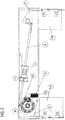
Fig. 2 is a side view of the resetting device according to the first embodiment; -
Fig. 3A is a top view of a resetting device according to a second embodiment of the present invention; -
Fig. 3B is a front view of the resetting device according to the second embodiment; -
Fig. 4 is a side view of the resetting device according to the second embodiment; -
Fig. 5 is a side view of a safety gear according to the first and second embodiment; -
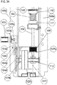
Fig. 6 is a front view of the safety gear shown inFig. 5 -
Figs. 1A ,1B and2 show an actuator having a resetting device 1 according to a first embodiment the invention. The actuator comprises aframe 6 which is provided on the bottom of an elevator car (not shown) or a counterweight (not shown). Theframe 6 comprises twoadjacent beams safety gears 14l, 14r on their lower sides on both longitudinal ends of theframe 6. The safety gears 14l, 14r are configured to engage with a guide rail (not shown) provided in an elevator shaft in which the elevator travels. The safety gears 14l, 14r comprise brakingwedges 15 which, when being pulled up, are clamped between respectivecounter wedges 16 of thesafety gears 14l, 14r and the guide rail so as to brake the elevator car/counterweight. The brakingwedges 15 are pulled up byactuation levers 7l, 7r which are mounted between thebeams frame 6 in a manner to be rotatable about shafts. In more detail, when the left actuator lever 7l rotates in the clockwise direction inFig. 2 , thebrake wedges 15 of the left safety gear 14l are pulled upward inFig. 1B so as to be clamped between thecounter wedges 16 and the guide rail. Further, when theright actuator lever 7r rotates in the counterclockwise direction, the brake wedges of theright safety gear 14r are pulled upward so as to be clamped between the counter wedges and the guide rail. In other words, theactuation levers 7l, 7r are operatively connected to thesafety gears 14l, 14r. - The
actuation levers 7l, 7r are connected to each other by a synchronizingrod 9. Afirst spring seat 10 is mounted to the outer circumference of the synchronizingrod 9 and asecond spring seat 11 is mounted to thebeam 6a in a manner that the synchronizingrod 9 penetrates thesecond spring seat 11. Anactuation spring 2 is seated between the first andsecond spring seat rod 9 passes through the inner space of the coil spring. - As can be seen in
Fig 2 , the left end of the synchronizingrod 9 is attached to an upper portion of the left actuation lever 7l, and the right end of the synchronizingrod 9 is connected to a lower portion of theright actuation lever 7r. Hence, when the synchronizingrod 9 is moved to the right side inFig. 2 , the left actuation lever 7l is rotated in the clockwise direction and theright actuation lever 7r is rotated in the counterclockwise direction. - Now, the resetting device 1 according to the present embodiment is described in detail. The resetting device 1 comprises an
electric motor 3, a planetary gear set 4, abrake shaft 13, abrake disc 12, and abrake 5. Theelectric motor 3 is mounted to the outer surface of thebeam 6a and thebrake 5 is mounted to the outer surface of thebeam 6b. The planetary gear set 4 is arranged between the twobeams electric motor 3 penetrates thebeam 6a and is connected to the carrier of the planetary gear set 4. Thebrake shaft 13 penetrates theother beam 6b and is connected to the sun gear of the planetary gear set 4 between thebeams brake disc 12 is attached to thebrake shaft 13 on the outside of thebeam 6b. The left actuation lever 7l is attached to the outer circumference of the ring gear. Thebrake 5 is attached to thebeam 6b at a position wherebrake shoes brake disc 12 so as to brake the rotational movement of thebrake disc 12. - In the planetary gear set 4, the gear ratio between the ring gear, i.e. the output of torque, and the carrier, i.e. the input of torque from the electric motor, is as large as possible. As a result, the input torque provided by the
electric motor 3 can be small such that theelectric motor 3 can be designed small. Further, the gear ratio between the ring gear and the sun gear is as small as possible. As a result, the torque to be applied to the sun gear so as to hold the sun gear stationary for allowing transmission of the input torque from theelectric motor 3 to the ring gear, which applies a large torque to the actuation lever 7l, can be small. Hence, thebrake 5 can be designed to be small. - The left actuation lever 7l comprises a holding plate (magnet armature) 7p at a position on the lower right side of the left actuation lever 7l in
Fig. 2 . Further, a holdingmagnet 8 is attached to the inner surface of thebeam 6b via a holdingbracket 8a and thus between thebeams magnet 8 is provided at a position at which the holdingplate 7p is in surface contact with the holdingmagnet 8 when the left actuation lever 7l is in the un-activated state. Thus, when holdingmagnet 8 is energized, the left actuation lever 7l is held in the un-activated state by the holdingmagnet 8. - Now, the operation of the actuator of this embodiment will be described.
Fig. 2 shows the un-activated state of the actuator in which thesafety gears 7l, 7r are not activated. In the un-activated state, thebrake 5 is not operated such that thebrake disc 12 and hence the sun gear of the planetary gear set 4 can freely rotate. When a ropeless overspeed governor (non shown) indicates that the elevator travel speed exceeds an predetermined tripping or activation speed at which the movement of the elevator car or the counterweight must be stopped, the holdingmagnet 8 is de-energized by a control unit (not shown). As a result, the left actuation lever 7l is free to rotate and theactuation spring 2 is no longer held in the compressed state. Hence, theactuation spring 2 pushes thefirst spring seat 10 to the right side together with thesynchronization lever 9 such that the left actuation lever 7l is rotated in the clockwise direction and theright actuation lever 7r is rotated in the counterclockwise direction. As has been described above, the rotations of theactuation levers 7l, 7r pull the brake wedges of the safety gears upward such that the elevator car/counterweight is braked at the guide rail. - Since the
brake 5 is not operated and the sun gear is free to rotate, the rotation of the ring gear connected to the left actuation lever 7l is not transmitted to the planetary gears such that the rotation of the left actuation lever 7l is not hindered by theelectric motor 3. - So as to reset the actuator, the
brake 5 is operated such that thebrake disc 12 is held stationary with respect to theframe 6. As a result, the sun gear is held stationary, i.e. the sun gear cannot rotate. Hence, the rotation of the carrier connected to the motor shaft of theelectric motor 3 can be transmitted to the ring gear connected to the left actuation lever 7l. Next, theelectric motor 3 is operated in a direction to rotate the ring gear of the planetary gear set 4 and thus the left actuation lever 7l in the counterclockwise direction. During this rotational movement of the left actuation lever 7l, thesynchronization rod 9 connected to the upper portion of the left actuation lever 7l is moved to the left side against the spring force of theactuation spring 2. As a result, theactuation spring 2 is compressed. When the holdingplate 7p comes into contact with the holdingmagnet 8, the holdingmagnet 8 is energized and thus holds the left actuation lever 7l against the spring force of theactuation spring 2. Then, theelectric motor 3 and thebrake 5 are de-energized. Now, resetting of the actuator is finished. -
Figs. 3A ,3B and4 show an actuator having a resetting device 101 according to a second embodiment the invention. The actuator comprises aframe 106 which is provided on the bottom of an elevator car (not shown) or a counterweight (not shown). Theframe 106 comprises twoadjacent beams safety gears 114l, 114r on their lower side on both longitudinal ends of theframe 106. The safety gears 114l, 114r are configured to engage with a guide rail (not shown) provided in an elevator shaft. The safety gears 114l, 114r comprisebrake wedges 115 which, when being pulled up inFig. 3B , are clamped between respectivecounter wedges 116 of the safety gears 114l, 114r and the guide rail so as to brake the elevator car/counterweight. Thebrake wedges 115 are pulled up byactuation levers 107l, 107r which are mounted to thebeams frame 106 in a manner to be rotatable about shafts. In more detail, when the left actuator lever 107l rotates in the clockwise direction inFig. 4 , thebrake wedges 115 of the left safety gear 114l are pulled upward inFig. 3B so as to be clamped between thecounter wedges 116 and the guide rail. Further, when theright actuator lever 107r rotates in the counterclockwise direction, thebrake wedges 115 of theright safety gear 114r are pulled upward so as to be clamped between the counter wedges and the guide rail. In other words, the actuation levers 107l, 107r are operatively connected to thesafety levers 114l, 114r. - Making reference to
Fig. 4 , the actuation levers 107l, 107r are connected to each other by a synchronizingrod 109. Afirst spring seat 110 is mounted to the outer circumference of the synchronizingrod 109 and asecond spring seat 111 is mounted to thebeam 106a in a manner that the synchronizingrod 109 penetrates thesecond spring seat 111. Anactuation spring 2 is seated between the first andsecond spring seat rod 109 passes through the inner space of the coil spring. - As can be seen in
Fig. 4 , the left end of the synchronizingrod 109 is attached to a lower portion of the left actuation lever 107l, and the right end of the synchronizingrod 109 is connected to an upper portion of theright actuation lever 107r. Hence, when the synchronizingrod 109 is moved to the left side inFig. 4 , the left actuation lever 107l is rotated in the clockwise direction and theright actuation lever 107r is rotated in the counterclockwise direction. - Now, the resetting device 101 according to the present embodiment is described in detail. The resetting device 101 comprises an
electric motor 103, adouble gear mechanism 104, a drivenshaft 113, and an electro-magnetic clutch 105. - The
electric motor 103 is attached to the outer surface of thebeam 106b and comprises amotor shaft 103a provided with adrive pinion 103b. - The
double gear mechanism 104 is provided outside thebeam 106b and comprises a first gear 104a and asecond gear 104b which are provided on a commonfirst transmission shaft 104c which is rotatably attached to thebeam 106b via a bearing. The first gear 104a has a larger diameter than that of thedrive pinion 103b and that of thesecond gear 104b. Further, the first gear 104a is in mesh with thedrive pinion 103b. - The
double gear mechanism 104 further comprises athird gear 104d which is attached to asecond transmission shaft 104e and which is in mesh with thesecond gear 104b. Thesecond transmission shaft 104e is supported by thebeam 106b and is connected to anelectromagnetic clutch 105. - The
electromagnetic clutch 105 is provided between thedouble gear mechanism 104 and theright actuation lever 114r and is connected to thesecond transmission shaft 104e as well as to the drivenshaft 113 to which theright actuation lever 114r is attached. When the electro-magnetic clutch 105 is engaged, the rotation of thesecond transmission shaft 104e is transmitted to the drivenshaft 113 and vice versa. When the electro-magnetic clutch 105 is disengaged, the rotation of thesecond transmission shaft 104e is not transmitted to the drivenshaft 113 and vice versa. Theelectromagnetic clutch 105 is configured to be engaged when supplied with electricity and to be disengaged when no electricity is supplied. - The
right actuation lever 107r comprises a holding plate (magnet armature) 107p at a position on the lower left side of theright actuation lever 107r inFig. 4 . A holdingmagnet 108 is attached to thebeam 106a at a position in which the holding plate 107p is in surface contact with the holdingmagnet 108 when the holdingmagnet 108 is energized. - Now, the operation of the actuator of this embodiment is described.
Fig. 4 shows an un-activated state of the actuator in which the safety gears 107l, 107r are not activated. In the un-activated state, the electromagnetic clutch is not engaged such that the drivenshaft 113 can freely rotate. When a ropeless overspeed governor (non shown) indicates that the elevator travel speed exceeds an predetermined tripping speed, the holdingmagnet 108 is de-energized by a control unit (not shown). As a result, theright actuation lever 107r is free to rotate and theactuation spring 102 is no longer held in the compressed state. Hence, theactuation spring 102 pushes thefirst spring seat 110 to the left side inFig. 4 together with thesynchronization lever 109 such that theright actuation lever 107r is rotated in the counterclockwise direction and the left actuation lever 107l is rotated in the clockwise direction. As has been described above, the rotations of the actuation levers 107l, 107r pull the brake wedges of the safety gears 114r, 114l upward such that the elevator car/counterweight is braked at the guide rail. - Since the
electromagnetic clutch 105 is not operated, the rotation of the drivenshaft 113 connected to theright actuation lever 107r is not transmitted to thesecond transmission shaft 104e such that the rotation of theright actuation lever 107r is not hindered by theelectric motor 103. - So as to reset the actuator, the electro-
magnetic clutch 105 is engaged such that the rotation of thesecond transmission shaft 104e can be transmitted to the drivenshaft 113 connected to theright actuation lever 107r. Next, theelectric motor 103 is operated in a direction to rotate theright actuation lever 107r in the clockwise direction inFig. 4 . During this rotation movement of theright actuation lever 107r, thesynchronization rod 109 connected to the upper portion of theright actuation lever 107r is moved to the right side against the spring force of theactuation spring 102. As a result, theactuation spring 102 is compressed. When the holding plate 107p comes into contact with the holdingmagnet 108, the holdingmagnet 108 is energized and thus holds theright actuation lever 107r against the spring force of theactuation spring 102. Then, theelectric motor 103 and the electro-magnetic clutch 105 are de-energized. Now, resetting of the actuator is finished. - Next, the
safety gear 14r, l; 114r, l is described in more detail with reference toFigs. 5 and6 . - As can be seen especially in
Fig. 6 , thesafety gear 14r, l; 114r, l comprises awedge chamber 19 for accommodating thebrake wedges 15 and thecounter wedges 16. Eachbrake wedge 15 comprises aguide groove 21 for guiding thebrake wedge 15 with respect to guidepins 22 mounted to thewedge chamber 19. The upper ends of thebrake wedges 15 are connected to the associated actuation levers 7l,r or 107l, r, respectively. In the front view ofFig. 6 , thebrake wedges 15 have a substantial triangular shape with an inner lateral side and an outer lateral side. This inner lateral side is oriented substantially vertical and comprises afriction surface 20 acting on the elevator guide rail when thesafety gear 14r, l; 114r, l is activated. The outer lateral side of thebrake wedge 15 is inclined with respect to the vertical direction and is formed with agroove 15a for accommodatingballs 23a. The outer lateral side is inclined such that the upper end of thebrake wedge 15 has a smaller width in the lateral direction than the lower end thereof. - The
counter wedges 16 have a substantially triangular shape when seen in the front view ofFig. 6 . The inner lateral side of thecounter wedges 16 is substantially parallel to the outer lateral side of theadjacent brake wedge 15 and is formed with a groove for accommodating theballs 23a in common withgroove 15a of thebrake wedge 15. As a result, thebrake wedge 15 and thecounter wedge 16 can slide with respect to each other. - The outer lateral sides of the
counter wedges 16 are inclined with respect to the vertical direction such that the lower end of thecounter wedge 16 has a smaller width in the lateral direction than the upper end thereof. Agroove 16a is formed in the outer lateral side of the counter wedge so as to accommodatedballs 23b which are also accommodated in a groove of an inner lateral side of thewedge chamber 19, which is substantially parallel to the outer lateral side of thecounter wedge 16. As a result, thecounter wedge 16 can slide within thewedge chamber 19. - Compression springs 17 are connected to the upper ends of the
counter wedges 16 and to the upper end of thewedge chamber 19, respectively, by means of retention screws 18. The compression springs 17 are oriented such that their spring forces act in parallel to the outer lateral side of thewedge 16 and the inner lateral side of thewedge chamber 19 which act as guide surfaces for thecounter wedges 16. - When the
safety gear 14r, l; 114r, l is activated by means of the actuation levers 7l,r or 107 l,r, thebrake wedges 15 are pulled upwardly to a larger extent than thecounter wedges 16 are pressed against the compression springs 17. Due to the inclined lateral sides of thewedges brake wedges 15 are pressed inwardly such that the friction surfaces 20 apply a braking force to the elevator guide rail due to which the elevator car is stopped. - After the stop, and after the actuation of the safety gear is released, the elevator car is raised with a hoisting machine such that the
brake wedges 15 are moved in the opposite direction with respect to thecounter wedges 16. At this time, the compression springs 17 apply a pressing force to thecounter wedges 16 in the downward direction such that thebrake wedges 15 and thecounter wedges 16 are pressed back into their initial position. - The present invention is not limited to the above embodiments.
- In the second embodiment, the electro-magnetic clutch is provided between the double gear mechanism and the actuation lever. However, the electric clutch can also be provided between the electric motor and the double gear mechanism.
Claims (15)
- A resetting device (1; 101) for resetting an actuator for actuating a safety gear (14l, 14r; 114l; 114r) of an elevator, the resetting device (1; 101) comprising:an actuation spring (2; 102) to be brought into a compressed state by a resetting force;an electric motor (3; 103) for providing the resetting force; anda transmission means (4, 104) for transmitting the resetting force of the electric motor (3; 103) to the actuation spring (2; 102), wherein the transmission means provides a positive gear ratio.
- The resetting device (1; 101) according to claim 1, further comprising
an interruption means (5, 105) for interrupting the transmission of force between the electric motor (3; 103) and the actuation spring (2; 102) in a state in which the actuation spring (2; 102) is reset. - The resetting device (1; 101) according to claim 1 or 2, further comprising:a frame (6, 106);an actuation lever (7l, 7r; 107l, 107r) rotatably mounted to the frame (6, 106) and operatively connected to the safety gear (14l, 14r; 114l; 114r); anda holding magnet (8; 108) for holding the actuation lever (7l, 7r; 107l, 107r) in an un-activated position in which the actuation spring (2; 102) is reset and the safety gear (14l, 14r; 114l; 114r) is not activated, wherein the holding magnet is (8; 108) is fixed to the frame (6; 106).
- The resetting device (1; 101) according to any one of claims 1 to 3, further comprising:a synchronization rod (9; 109) connected to the actuation lever (7l, 7r; 107l, 107r);a first spring seat (10; 110) attached to the synchronization rod (9; 109);a second spring seat (11; 111) attached to the frame (6; 106), wherein the actuation spring (2; 102) is seated between the first and second spring seat (11; 111);a controller adapted to drive the electric motor (3; 103) until the actuation lever (7; 107) is brought into the un-activated position by the resetting force against a force of the actuation spring (2; 102), then to activate the holding magnet (8; 108) so as to hold the actuation lever (7; 107) in the un-activated position, and then to activate the interruption means (5; 105) so as to interrupt the transmission of force between the electric motor (3; 103) and the actuation spring (2; 102).
- The resetting device (101) according to any one of the preceding claims, wherein
the interruption means (105) is an electro-magnetic clutch provided between the electric motor (103) and the actuation lever (107). - The resetting device (101) according to claim 4, wherein
the electro-magnetic clutch (105) is adapted to interrupt the transmission of forces between the electric motor (103) and the actuation spring (102) when not being supplied with electricity. - The resetting device (101) according to any one of claims 1 to 5, wherein
the transmission means (104) is a double gear mechanism which is adapted to transmit the resetting force from the electric motor (103) to the electro-magnetic clutch (105) with a positive gear ratio. - The resetting device (1) according to any one of claims 1 to 3, whereinthe transmission means (4) is formed by a planetary gear set having a sun gear, a ring gear and a carrier carrying planetary gears which are in mesh with the sun gear and the ring gear, respectively, whereinthe ring gear is connected to the actuation lever (7l, 7r), andthe carrier is connected to the electric motor (3).
- The resetting device (1) according to claim 8, whereinthe sun gear is connected to a brake disc (12), and the resetting device further comprisesa brake (5) for applying a brake force to the brake disc (12); whereinthe interruption means is formed by the brake (5) being in a state of not applying a brake force to the brake disc (12) so as to allow the sun gear to rotate freely thus interrupting the transmission of forces between the electric motor (3) and the actuation spring (2).
- The resetting device (1) according to any one of claims 1 to 3, whereinthe transmission means (4) is formed by a planetary gear set having a sun gear, a ring gear and a carrier carrying planetary gears which are in mesh with the sun gear and the ring gear, respectively, whereinthe ring gear is connected to the actuation lever (71, 7r), andthe sun gear is connected to the electric motor (3).
- The resetting device (1) according to claim 10, whereinthe carrier is connected to a brake disc (12), and the resetting device further comprisesa brake (5) for applying a brake force to the brake disc (12); whereinthe interruption means is formed by the brake (5) being in a state of not applying a brake force to the brake disc (12) so as to allow the sun gear to rotate freely thus interrupting the transmission of forces between the electric motor (3) and the actuation spring (2).
- The resetting device (1) according to claim 9 or 11, wherein
the brake (5) is adapted to be in the state of not applying the brake force to the brake disc (12) when the brake (13) is not supplied with electricity. - The resetting device (1) according to any one of claims 8 to 12, wherein
the planetary gear set (4) is adapted to transmit the resetting force from the electric motor (3) to the actuation spring (2) with a positive gear ratio. - The resetting device (1) according to any one of the preceding claims, wherein
the safety gear (14r, 141) comprises a wedge chamber (19) and a brake wedge (15) acting on an elevator guide rail and activated by means of an actuation lever (14r, 14l; 114r, 114l) and counter wedge (16) movable along guide surfaces (20) provided in the wedge chamber (19). - The resetting device (1) according to claim 14, wherein
the safety gear (14r, 14l; 114r, 114l) is provided with pressure springs (17) attached with fixing screws (18) on their one ends to stop faces (21) of the wedge chamber (19) and by their other end to the wider ends of the counter wedges (16).
Priority Applications (3)
| Application Number | Priority Date | Filing Date | Title |
|---|---|---|---|
| EP18166112.5A EP3549896A1 (en) | 2018-04-06 | 2018-04-06 | Resetting device for resetting an actuator for actuating a safety gear of an elevator |
| CN201910270717.0A CN110342366B (en) | 2018-04-06 | 2019-04-04 | Reset device for resetting an actuator for actuating a safety gear of an elevator |
| US16/374,956 US11427436B2 (en) | 2018-04-06 | 2019-04-04 | Resetting device for resetting an actuator for actuating a safety gear of an elevator |
Applications Claiming Priority (1)
| Application Number | Priority Date | Filing Date | Title |
|---|---|---|---|
| EP18166112.5A EP3549896A1 (en) | 2018-04-06 | 2018-04-06 | Resetting device for resetting an actuator for actuating a safety gear of an elevator |
Publications (1)
| Publication Number | Publication Date |
|---|---|
| EP3549896A1 true EP3549896A1 (en) | 2019-10-09 |
Family
ID=61913002
Family Applications (1)
| Application Number | Title | Priority Date | Filing Date |
|---|---|---|---|
| EP18166112.5A Withdrawn EP3549896A1 (en) | 2018-04-06 | 2018-04-06 | Resetting device for resetting an actuator for actuating a safety gear of an elevator |
Country Status (3)
| Country | Link |
|---|---|
| US (1) | US11427436B2 (en) |
| EP (1) | EP3549896A1 (en) |
| CN (1) | CN110342366B (en) |
Cited By (1)
| Publication number | Priority date | Publication date | Assignee | Title |
|---|---|---|---|---|
| EP3932844A1 (en) * | 2020-07-01 | 2022-01-05 | KONE Corporation | Safety gear arrangement, elevator system, and method for operating a safety gear of an elevator system |
Families Citing this family (9)
| Publication number | Priority date | Publication date | Assignee | Title |
|---|---|---|---|---|
| EP3733584A1 (en) * | 2019-05-03 | 2020-11-04 | Otis Elevator Company | Combined safety brake and safety actuation mechanism |
| WO2022038656A1 (en) * | 2020-08-17 | 2022-02-24 | 株式会社日立製作所 | Elevator device |
| CN112218452B (en) * | 2020-10-13 | 2021-08-03 | 北京凯盛安达电梯服务有限公司 | Elevator installation, maintenance and debugging simulation system convenient to operate |
| JP7558754B2 (en) | 2020-10-29 | 2024-10-01 | 株式会社日立製作所 | Emergency stop devices and elevators |
| WO2022162874A1 (en) * | 2021-01-29 | 2022-08-04 | 株式会社日立製作所 | Elevator apparatus |
| JP7545007B2 (en) * | 2022-03-17 | 2024-09-03 | 株式会社日立製作所 | Elevator Equipment |
| CN117657915A (en) * | 2022-08-25 | 2024-03-08 | 奥的斯电梯公司 | Elevator safety gear control device, elevator safety equipment and elevator system |
| US11975945B1 (en) | 2022-11-28 | 2024-05-07 | Otis Elevator Company | Frictionless safety brake actuator |
| ES3041446T3 (en) | 2022-11-29 | 2025-11-12 | Otis Elevator Co | Frictionless elevator safety brake actuator |
Citations (3)
| Publication number | Priority date | Publication date | Assignee | Title |
|---|---|---|---|---|
| US20070051563A1 (en) * | 2003-10-07 | 2007-03-08 | Jae-Hyuk Oh | Remotely resettable ropeless emergency stopping device for an elevator |
| JP2009227353A (en) * | 2008-03-19 | 2009-10-08 | Mitsubishi Electric Corp | Emergency stop device for elevator and checking method thereof |
| US20110226560A1 (en) | 2010-03-18 | 2011-09-22 | Josef Husmann | Elevator braking equipment |
Family Cites Families (9)
| Publication number | Priority date | Publication date | Assignee | Title |
|---|---|---|---|---|
| CH372099A (en) * | 1959-09-02 | 1963-09-30 | Inventio Ag | Electromechanical brake |
| FI98295C (en) * | 1991-11-18 | 1997-05-26 | Kone Oy | catching device |
| US6371261B1 (en) * | 1997-11-06 | 2002-04-16 | Otis Elevator Company | Molybdenum alloy elevator safety brakes |
| CA2544664C (en) * | 2004-05-25 | 2011-06-14 | Mitsubishi Denki Kabushiki Kaisha | Safety device for an elevator |
| JP4811901B2 (en) | 2004-06-03 | 2011-11-09 | ルネサスエレクトロニクス株式会社 | Semiconductor device |
| US8631909B2 (en) * | 2009-03-16 | 2014-01-21 | Otis Elevator Company | Electromagnetic safety trigger |
| WO2013092239A1 (en) * | 2011-12-21 | 2013-06-27 | Inventio Ag | Actuator for lift brake |
| JP6137805B2 (en) * | 2012-07-26 | 2017-05-31 | 曙ブレーキ工業株式会社 | Electric disc brake device |
| CN207175130U (en) * | 2017-08-31 | 2018-04-03 | 许昌宇德瑞达机电有限公司 | Self-resetting limiter of speed |
-
2018
- 2018-04-06 EP EP18166112.5A patent/EP3549896A1/en not_active Withdrawn
-
2019
- 2019-04-04 US US16/374,956 patent/US11427436B2/en active Active
- 2019-04-04 CN CN201910270717.0A patent/CN110342366B/en active Active
Patent Citations (3)
| Publication number | Priority date | Publication date | Assignee | Title |
|---|---|---|---|---|
| US20070051563A1 (en) * | 2003-10-07 | 2007-03-08 | Jae-Hyuk Oh | Remotely resettable ropeless emergency stopping device for an elevator |
| JP2009227353A (en) * | 2008-03-19 | 2009-10-08 | Mitsubishi Electric Corp | Emergency stop device for elevator and checking method thereof |
| US20110226560A1 (en) | 2010-03-18 | 2011-09-22 | Josef Husmann | Elevator braking equipment |
Cited By (2)
| Publication number | Priority date | Publication date | Assignee | Title |
|---|---|---|---|---|
| EP3932844A1 (en) * | 2020-07-01 | 2022-01-05 | KONE Corporation | Safety gear arrangement, elevator system, and method for operating a safety gear of an elevator system |
| US11679958B2 (en) | 2020-07-01 | 2023-06-20 | Kone Corporation | Safety gear arrangement, elevator system, and method for operating a safety gear of an elevator system |
Also Published As
| Publication number | Publication date |
|---|---|
| CN110342366A (en) | 2019-10-18 |
| US20190308846A1 (en) | 2019-10-10 |
| US11427436B2 (en) | 2022-08-30 |
| CN110342366B (en) | 2023-06-09 |
Similar Documents
| Publication | Publication Date | Title |
|---|---|---|
| US11427436B2 (en) | Resetting device for resetting an actuator for actuating a safety gear of an elevator | |
| CN102874669B (en) | Emergency braking device of elevator | |
| CN103648954A (en) | Brake device with electromechanical actuation | |
| JP2014508698A (en) | Elevator brake system | |
| JP4170295B2 (en) | Elevator braking device | |
| JPWO2008149413A1 (en) | Elevator safety device | |
| CN111712455A (en) | Emergency stop devices and elevators | |
| WO2019220505A1 (en) | Elevator safety device and elevator safety system | |
| CN102992139B (en) | Shutdown feature and the elevator possessing this shutdown feature | |
| JP6732695B2 (en) | Electromagnetic brake release device and elevator | |
| US11897731B2 (en) | Brake device, e.g. with an eccentric element, for braking a traveling body that can be moved in a guided manner along a guide rail in a movement direction | |
| CN110857210B (en) | Elevator safety brake, elevator and method for testing elevator safety brake | |
| UA57837C2 (en) | Sudden braking apparatus of a press | |
| JP7638993B2 (en) | Braking device for braking a moving vehicle which can be guided along a guide rail in the direction of travel, for example with a wedge-shaped braking element | |
| US5109958A (en) | Brake unit for an elevator hoist apparatus | |
| CN101676186B (en) | Braking device, hoister and elevator employing the braking device | |
| EP2868611B1 (en) | A brake assembly for an elevator | |
| SG185238A1 (en) | Brake releasing machine and elevator | |
| CN110436297B (en) | Brake disc release device, barring device, elevator rescue kit and method | |
| WO2010084563A1 (en) | Safety device for elevator | |
| EP3517473A1 (en) | Inertia brake for braking a governor rope of a governor system of an elevator system | |
| US11465884B2 (en) | Combined safety brake and safety actuation mechanism | |
| JPH0796432B2 (en) | Linear motor drive elevator | |
| CN115551794A (en) | Devices for actuating safety gear associated with elevator cars | |
| JP6710328B2 (en) | Elevator hoist |
Legal Events
| Date | Code | Title | Description |
|---|---|---|---|
| PUAI | Public reference made under article 153(3) epc to a published international application that has entered the european phase |
Free format text: ORIGINAL CODE: 0009012 |
|
| STAA | Information on the status of an ep patent application or granted ep patent |
Free format text: STATUS: THE APPLICATION HAS BEEN PUBLISHED |
|
| AK | Designated contracting states |
Kind code of ref document: A1 Designated state(s): AL AT BE BG CH CY CZ DE DK EE ES FI FR GB GR HR HU IE IS IT LI LT LU LV MC MK MT NL NO PL PT RO RS SE SI SK SM TR |
|
| AX | Request for extension of the european patent |
Extension state: BA ME |
|
| STAA | Information on the status of an ep patent application or granted ep patent |
Free format text: STATUS: REQUEST FOR EXAMINATION WAS MADE |
|
| 17P | Request for examination filed |
Effective date: 20200407 |
|
| RBV | Designated contracting states (corrected) |
Designated state(s): AL AT BE BG CH CY CZ DE DK EE ES FI FR GB GR HR HU IE IS IT LI LT LU LV MC MK MT NL NO PL PT RO RS SE SI SK SM TR |
|
| STAA | Information on the status of an ep patent application or granted ep patent |
Free format text: STATUS: EXAMINATION IS IN PROGRESS |
|
| 17Q | First examination report despatched |
Effective date: 20220217 |
|
| P01 | Opt-out of the competence of the unified patent court (upc) registered |
Effective date: 20230525 |
|
| GRAP | Despatch of communication of intention to grant a patent |
Free format text: ORIGINAL CODE: EPIDOSNIGR1 |
|
| STAA | Information on the status of an ep patent application or granted ep patent |
Free format text: STATUS: GRANT OF PATENT IS INTENDED |
|
| INTG | Intention to grant announced |
Effective date: 20231011 |
|
| STAA | Information on the status of an ep patent application or granted ep patent |
Free format text: STATUS: THE APPLICATION IS DEEMED TO BE WITHDRAWN |
|
| 18D | Application deemed to be withdrawn |
Effective date: 20240222 |