EP3549835A1 - Vehicle - Google Patents
Vehicle Download PDFInfo
- Publication number
- EP3549835A1 EP3549835A1 EP19157667.7A EP19157667A EP3549835A1 EP 3549835 A1 EP3549835 A1 EP 3549835A1 EP 19157667 A EP19157667 A EP 19157667A EP 3549835 A1 EP3549835 A1 EP 3549835A1
- Authority
- EP
- European Patent Office
- Prior art keywords
- road surface
- surface state
- decision unit
- hard
- decides
- Prior art date
- Legal status (The legal status is an assumption and is not a legal conclusion. Google has not performed a legal analysis and makes no representation as to the accuracy of the status listed.)
- Granted
Links
Images



Classifications
-
- B—PERFORMING OPERATIONS; TRANSPORTING
- B60—VEHICLES IN GENERAL
- B60T—VEHICLE BRAKE CONTROL SYSTEMS OR PARTS THEREOF; BRAKE CONTROL SYSTEMS OR PARTS THEREOF, IN GENERAL; ARRANGEMENT OF BRAKING ELEMENTS ON VEHICLES IN GENERAL; PORTABLE DEVICES FOR PREVENTING UNWANTED MOVEMENT OF VEHICLES; VEHICLE MODIFICATIONS TO FACILITATE COOLING OF BRAKES
- B60T8/00—Arrangements for adjusting wheel-braking force to meet varying vehicular or ground-surface conditions, e.g. limiting or varying distribution of braking force
- B60T8/17—Using electrical or electronic regulation means to control braking
- B60T8/1701—Braking or traction control means specially adapted for particular types of vehicles
- B60T8/1706—Braking or traction control means specially adapted for particular types of vehicles for single-track vehicles, e.g. motorcycles
-
- B—PERFORMING OPERATIONS; TRANSPORTING
- B62—LAND VEHICLES FOR TRAVELLING OTHERWISE THAN ON RAILS
- B62J—CYCLE SADDLES OR SEATS; AUXILIARY DEVICES OR ACCESSORIES SPECIALLY ADAPTED TO CYCLES AND NOT OTHERWISE PROVIDED FOR, e.g. ARTICLE CARRIERS OR CYCLE PROTECTORS
- B62J45/00—Electrical equipment arrangements specially adapted for use as accessories on cycles, not otherwise provided for
- B62J45/40—Sensor arrangements; Mounting thereof
- B62J45/41—Sensor arrangements; Mounting thereof characterised by the type of sensor
- B62J45/414—Acceleration sensors
-
- B—PERFORMING OPERATIONS; TRANSPORTING
- B62—LAND VEHICLES FOR TRAVELLING OTHERWISE THAN ON RAILS
- B62J—CYCLE SADDLES OR SEATS; AUXILIARY DEVICES OR ACCESSORIES SPECIALLY ADAPTED TO CYCLES AND NOT OTHERWISE PROVIDED FOR, e.g. ARTICLE CARRIERS OR CYCLE PROTECTORS
- B62J45/00—Electrical equipment arrangements specially adapted for use as accessories on cycles, not otherwise provided for
- B62J45/40—Sensor arrangements; Mounting thereof
- B62J45/42—Sensor arrangements; Mounting thereof characterised by mounting
-
- B—PERFORMING OPERATIONS; TRANSPORTING
- B62—LAND VEHICLES FOR TRAVELLING OTHERWISE THAN ON RAILS
- B62J—CYCLE SADDLES OR SEATS; AUXILIARY DEVICES OR ACCESSORIES SPECIALLY ADAPTED TO CYCLES AND NOT OTHERWISE PROVIDED FOR, e.g. ARTICLE CARRIERS OR CYCLE PROTECTORS
- B62J45/00—Electrical equipment arrangements specially adapted for use as accessories on cycles, not otherwise provided for
- B62J45/40—Sensor arrangements; Mounting thereof
- B62J45/42—Sensor arrangements; Mounting thereof characterised by mounting
- B62J45/423—Sensor arrangements; Mounting thereof characterised by mounting on or besides the wheel
-
- B—PERFORMING OPERATIONS; TRANSPORTING
- B62—LAND VEHICLES FOR TRAVELLING OTHERWISE THAN ON RAILS
- B62K—CYCLES; CYCLE FRAMES; CYCLE STEERING DEVICES; RIDER-OPERATED TERMINAL CONTROLS SPECIALLY ADAPTED FOR CYCLES; CYCLE AXLE SUSPENSIONS; CYCLE SIDECARS, FORECARS, OR THE LIKE
- B62K25/00—Axle suspensions
- B62K25/04—Axle suspensions for mounting axles resiliently on cycle frame or fork
- B62K25/06—Axle suspensions for mounting axles resiliently on cycle frame or fork with telescopic fork, e.g. including auxiliary rocking arms
- B62K25/08—Axle suspensions for mounting axles resiliently on cycle frame or fork with telescopic fork, e.g. including auxiliary rocking arms for front wheel
-
- B—PERFORMING OPERATIONS; TRANSPORTING
- B62—LAND VEHICLES FOR TRAVELLING OTHERWISE THAN ON RAILS
- B62L—BRAKES SPECIALLY ADAPTED FOR CYCLES
- B62L1/00—Brakes; Arrangements thereof
-
- B—PERFORMING OPERATIONS; TRANSPORTING
- B60—VEHICLES IN GENERAL
- B60T—VEHICLE BRAKE CONTROL SYSTEMS OR PARTS THEREOF; BRAKE CONTROL SYSTEMS OR PARTS THEREOF, IN GENERAL; ARRANGEMENT OF BRAKING ELEMENTS ON VEHICLES IN GENERAL; PORTABLE DEVICES FOR PREVENTING UNWANTED MOVEMENT OF VEHICLES; VEHICLE MODIFICATIONS TO FACILITATE COOLING OF BRAKES
- B60T2210/00—Detection or estimation of road or environment conditions; Detection or estimation of road shapes
- B60T2210/10—Detection or estimation of road conditions
- B60T2210/14—Rough roads, bad roads, gravel roads
-
- B—PERFORMING OPERATIONS; TRANSPORTING
- B62—LAND VEHICLES FOR TRAVELLING OTHERWISE THAN ON RAILS
- B62K—CYCLES; CYCLE FRAMES; CYCLE STEERING DEVICES; RIDER-OPERATED TERMINAL CONTROLS SPECIALLY ADAPTED FOR CYCLES; CYCLE AXLE SUSPENSIONS; CYCLE SIDECARS, FORECARS, OR THE LIKE
- B62K25/00—Axle suspensions
- B62K25/04—Axle suspensions for mounting axles resiliently on cycle frame or fork
- B62K2025/044—Suspensions with automatic adjustment
Definitions
- the present invention relates to a vehicle.
- a vehicle in which a state of a road surface is decided by an acceleration sensor mounted on the vehicle and a characteristic of a suspension is adjusted on the basis of a result of the decision (for example, refer to Patent Document 1).
- Patent Document 1 Japanese Patent Laid-Open No. Hei 10-315733
- the present invention has been made in view of such a situation as described above, and it is an object of the present invention to make it possible for a vehicle to decide a state of a road surface with a simple structure and high accuracy.
- a vehicle including a suspension (18) that supports a front wheel (2) thereon, and a road surface state decision unit (62) that decides a road surface state by detection of a sensor (50), in which the sensor (50) is provided at a lower portion of the suspension (18) and is capable of detecting an acceleration at least in a one-axis direction;
- the suspension (18) is a front fork (18) that supports the front wheel (2) of the vehicle that is a saddle riding vehicle (1);
- the front fork (18) includes a bottom case (30) that connects a lower portion of the front fork (18) and an axle (2a) of the front wheel (2) to each other; and the sensor (50) is attached to the bottom case (30).
- the vehicle may be configured such that the road surface state decision unit (62) decides a road surface state based on a detection value in an extension direction of the suspension (18).
- a vehicle including a suspension (18) that supports a wheel (2) at a lower portion thereof, and a road surface state decision unit (62) that decides a road surface state by detection of a sensor (50), in which the sensor (50) is provided at the lower portion of the suspension (18) and is capable of detecting an acceleration at least in a one-axis direction; and the road surface state decision unit (62) decides a road surface state based on a detection value in an extension direction of the suspension (18).
- the vehicle may be configured such that a brake caliper attachment hole (43c) to which a brake caliper (37) for braking the wheel (2) is attached is provided in the bottom case (30), and the sensor (50) is fastened to the brake caliper attachment hole (43c) together with the brake caliper (37).
- the vehicle may be configured such that the sensor (50) is disposed between an axle (2a) of the wheel (2) and the brake caliper (37) as viewed in side elevation of the vehicle.
- the vehicle may be configured such that the road surface state decision unit (62) is capable of deciding a hard road surface (H) and a soft road surface (S) that is softer in road surface state than the hard road surface (H), and the road surface state decision unit (62) decides that the road surface state is the hard road surface (H) taking it as a trigger that a variation time period ( ⁇ AB) after an acceleration reaches a first threshold value (A) until the acceleration reaches a second threshold value (B) that is lower than the first threshold value (A) is within a given time period.
- ⁇ AB variation time period
- the vehicle may be configured such that the road surface state decision unit (62) decides that the road surface state is the soft road surface (S) taking it as a trigger that the variation time period ( ⁇ AB) is longer than the given time period.
- the vehicle may be configured such that, where it is decided that the road surface state is the soft road surface (S), the road surface state decision unit (62) transits to a temporary mode (I) if the trigger of the hard road surface (H) is detected; if the trigger of the hard road surface (H) is detected within a second given time period (p2) after the transition to the temporary mode (I), then the road surface state decision unit (62) decides that the road surface state is the hard road surface (H), but if the trigger of the hard road surface (H) is not detected within the second given time period (p2) after the transition to the temporary mode (I), then the road surface state decision unit (62) decides that the road surface state is the soft road surface (S); and, in the temporary mode (I), the road surface state decision unit (62) decides that the road surface state is the hard road surface (H).
- the vehicle may be configured such that, if a third given time period (p3) elapses after the trigger of the hard road surface (H) is detected, then the road surface state decision unit (62) decides that the road surface state is the soft road surface (S).
- the vehicle may be configured such that, where it is decided that the road surface state is the hard road surface (H), every time the trigger of the hard road surface (H) is detected, the road surface state decision unit (62) resets a count of a timer and starts counting of the timer, and if the count of the timer reaches a given value, then the road surface state decision unit (62) decides that the road surface state is the soft road surface (S).
- the vehicle includes a suspension that supports a front wheel thereon, and a road surface state decision unit that decides a road surface state by detection of a sensor.
- the sensor is provided at a lower portion of the suspension and is capable of detecting an acceleration at least in a one-axis direction.
- the suspension is a front fork that supports the front wheel of the vehicle that is a saddle riding vehicle.
- the front fork includes a bottom case that connects a lower portion of the front fork and an axle of the front wheel to each other.
- the sensor is attached to the bottom case.
- the sensor for detecting the acceleration is attached to the bottom case of the front fork of the saddle riding vehicle, the sensor can be provided in a simple structure and the acceleration acting on the front wheel can be detected effectively. Further, the road surface state decision unit can decide a state of the road surface with high accuracy from a detection value of the acceleration.
- the road surface state decision unit may decide a road surface state based on a detection value in an extension direction of the suspension. Since, in the extension direction of the suspension, the variation amount of the damping force with respect to a stroke of the suspension is greater than that in the compression direction of the suspension, the road surface state can be decided with high accuracy by deciding the road surface state from the acceleration in the extension direction.
- the vehicle includes a suspension that supports a wheel at a lower portion thereof, and a road surface state decision unit that decides a road surface state by detection of a sensor.
- the sensor is provided at the lower portion of the suspension and is capable of detecting an acceleration at least in a one-axis direction.
- the road surface state decision unit decides a road surface state based on a detection value in an extension direction of the suspension.
- the sensor since the sensor is attached to the lower portion of the suspension, the sensor can be provided in a simple structure and an acceleration acting on the front wheel can be detected effectively. Further, the road surface state decision unit can decide a state of the road surface with high accuracy from the detection value of the acceleration. Further, since, in the extension direction of the suspension, the variation amount of the damping force with respect to a stroke of the suspension is greater than that in the compression direction of the suspension, the road surface state can be decided with high accuracy by deciding the road surface state from the acceleration in the extension direction.
- a brake caliper attachment hole to which a brake caliper for braking the wheel is attached may be provided in the bottom case, and the sensor may be fastened to the brake caliper attachment hole together with the brake caliper.
- the senor may be disposed between an axle of the wheel and the brake caliper as viewed in side elevation of the vehicle.
- the sensor can be provided compactly utilizing a space between the axle and the brake caliper and the sensor can be prevented from standing out, and therefore, the appearance performance is good.
- the road surface state decision unit may be capable of deciding a hard road surface and a soft road surface that is softer in road surface state than the hard road surface. Further, the road surface state decision unit may decide that the road surface state is the hard road surface taking it as a trigger that a variation time period after an acceleration reaches a first threshold value until the acceleration reaches a second threshold value that is lower than the first threshold value is within a given time period.
- the hard road surface can be decided with high accuracy on the basis of a time period until after the acceleration decreases from the first threshold value to the second threshold value.
- the road surface state decision unit may decide that the road surface state is the soft road surface taking it as a trigger that the variation time period is longer than the given time period.
- the soft road surface can be decided with high accuracy on the basis of a time period until after the acceleration decreases from the first threshold value to the second threshold value.
- the road surface state decision unit may transit to a temporary mode if the trigger of the hard road surface is detected. Then, if the trigger of the hard road surface is detected within a second given time period after the transition to the temporary mode, then the road surface state decision unit may decide that the road surface state is the hard road surface, but if the trigger of the hard road surface is not detected within the second given time period after the transition to the temporary mode, then the road surface state decision unit may decide that the road surface state is the soft road surface. Further, in the temporary mode, the road surface state decision unit may decide that the road surface state is the hard road surface.
- the road surface state decision unit can quickly transit from the decision of the soft road surface to the decision of the hard road surface.
- the road surface state decision unit can return to the decision of the soft road surface in response to the actual road surface state.
- the road surface state decision unit may decide that the road surface state is the soft road surface.
- the road surface state decision unit can quickly return from the decision of the hard road surface to the decision of the soft road surface, and where the actual road surface state is the soft road surface, transition to the decision of the hard road surface is suppressed.
- the road surface state decision unit may reset a count of a timer and starts counting of the timer, and if the count of the timer reaches a given value, then the road surface state decision unit may decide that the road surface state is the soft road surface.
- the road surface state decision unit can quickly return from the decision of the hard road surface to the decision of the soft road surface.
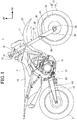
- FIG. 1 is a right side elevational view of a motorcycle 1 according to a first embodiment of the present invention. It is to be noted that, in FIG. 1 , where elements are provided in left and right pair, only an element on the right side is depicted including a reference character therefor.
- the motorcycle 1 is a vehicle in which an engine 10 as a power unit is supported on a vehicle body frame F, and a steering system 11 for supporting a front wheel 2 (vehicle wheel) for steering movement is supported for steering movement at a front end of the vehicle body frame F and a swing arm 12 that supports a rear wheel 3 is provided at a rear portion of the vehicle body frame F.
- a steering system 11 for supporting a front wheel 2 (vehicle wheel) for steering movement is supported for steering movement at a front end of the vehicle body frame F and a swing arm 12 that supports a rear wheel 3 is provided at a rear portion of the vehicle body frame F.
- the motorcycle 1 is a saddle riding vehicle in which a seat 13 on which the driver is to be seated astride is provided above a rear portion of the vehicle body frame F.
- the steering system 11 is supported on a head pipe 15 provided at a front end of the vehicle body frame F.
- the steering system 11 includes a steering shaft (not depicted) supported for rotation on the head pipe 15, a top bridge 16 fixed to an upper end of the steering shaft, a bottom bridge 17 fixed to a lower end of the steering shaft, and a front fork having front forks 18 (suspensions) disposed in pair on the left and right sides of the head pipe 15 and supported on the top bridge 16 and the bottom bridge 17.
- An axle 2a is supported at a lower end portion of the front forks 18 provided in pair on the left and right sides.
- the front wheel 2 is disposed between the left and right front forks 18 and is supported on the axle 2a.
- a handlebar 19 that is used for steering of the front wheel 2 by the driver is attached to the top bridge 16.
- a front fender 20 is attached to the bottom bridge 17 such that it covers the front wheel 2 from above.
- the swing arm 12 is supported at a front end portion thereof on a pivot shaft 21 provided at a rear portion of the vehicle body frame F such that the swing arm 12 rocks upwardly and downwardly around the pivot shaft 21.
- a rear suspension 22 is stretched between the front end of the swing arm 12 and the vehicle body frame F.
- Driving force of the engine 10 is transmitted to the rear wheel 3 through a chain 23.
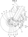
- FIG. 2 is a left side elevational view of peripheral elements of a lower portion of the front fork 18.
- FIG. 3 is a perspective view of the lower portion of the left side front fork 18 of the front fork as viewed from the rear side.
- the front forks 18 are disposed in a posture inclined rearwardly with respect to the vertical direction as viewed in side elevation of the vehicle.
- Each of the front forks 18 of the front fork includes a fixed tube 25 fixed to the top bridge 16 and the bottom bridge 17, a movable tube 26 that strokes in an axial direction with respect to the fixing tube 25, a coil spring (not depicted) that is provided in the tube and is compressed in a stroke direction of the front fork 18, a damping force generation unit (not depicted), and a suspension adjustment mechanism 27 ( FIG. 4 ) that adjusts a behavior characteristic of the front fork 18.
- the front fork 18 is a telescopic suspension in which the movable tube 26 strokes in an axial direction with respect to the fixed tube 25.
- the coil spring described above biases the front fork 18 in its extension direction and absorbs a shock from the road surface.
- the damping force generation unit damps vibration of the front fork 18 in its contraction direction and extension direction.
- the damping force generation unit damps the stroke (vibration) of the front fork 18 by the resistance of the hydraulic oil in the front fork 18.
- the suspension adjustment mechanism 27 is driven by an actuator and can change the initial load of the coil spring of the front fork 18 and the damping force of the front fork 18.
- the movable tube 26 includes a tube main body 29 that fits from below and slidably moves in the fixed tube 25, and a bottom case 30 coupled to a lower end portion of the tube main body 29.
- the front wheel 2 is disposed between the left and right bottom cases 30.
- the front wheel 2 is supported for rotation on the axle 2a extending between the left and right bottom cases 30.
- the front wheel 2 includes a tire 31 and a wheel 32 to which the tire 31 is attached.
- the wheel 32 includes an annular rim 33 to which the tire 31 is attached, a hub 34 supported for rotation on the axle 2a, and spokes (not depicted) that connect the hub 34 and the rim 33 to each other.
- the hub 34 is formed in a circular shape as viewed in side elevation and has, at the center thereof, an axle hole in which the axle 2a is fitted.
- the spokes extend radially to the diametrically outer sides from an outer circumference of the hub 34 and are coupled to an inner circumference of the rim 33.
- the motorcycle 1 includes a front brake system 35 for braking the front wheel 2.
- the front brake system 35 includes a brake disk 36 that rotates together with the front wheel 2, a brake caliper 37 that sandwiches and presses the brake disk 36 under hydraulic pressure to brake the front wheel 2, and a brake hose 38 that supplies hydraulic pressure to the brake caliper 37 therethrough.
- the brake disk 36 is disposed coaxially with the axle 2a and fixed to the hub 34.
- the brake disk 36 is disposed between the left side front fork 18 and the wheel 32 in the vehicle widthwise direction.
- the brake caliper 37 is fixed to the left side bottom case 30.
- the brake caliper 37 is disposed behind the axle 2a and the bottom case 30 as viewed in side elevation of the vehicle.
- the brake caliper 37 includes a caliper supporting member 39 fixed to the bottom case 30, and a caliper main body 40 that sandwiches and presses the brake disk 36 through a brake pad (not detected).
- the brake caliper 37 is fixed to the bottom case 30 by caliper fixation bolts 41a and 41b that are screwed at an upper portion and a lower portion of a front portion of the caliper supporting member 39, respectively.
- the caliper main body 40 is supported at a rear portion of the caliper supporting member 39.
- the brake hose 38 is led out from a rear portion of the caliper main body 40 and extends upwardly.
- the bottom case 30 includes a bottom case main body 42 coupled to a lower end portion of the tube main body 29, and caliper stays 43a and 43b extending rearwardly from a rear face of the bottom case main body 42.
- the bottom case main body 42 has, at a lower portion of a front portion thereof as viewed in side elevation of the vehicle, an axle supporting hole 44 that supports the axle 2a.
- a wheel speed sensor 45 is attached to an upper portion of a front portion of the bottom case main body 42.
- the wheel speed sensor 45 detects rotation of the front wheel 2 by detecting a ring-shaped pulser rotor 46 attached to the hub 34.
- the axle 2a and the wheel speed sensor 45 are positioned forwardly of the axial line 18a of the front fork 18.
- a cable 45a of the wheel speed sensor 45 extends rearwardly along an outer side face of the bottom case main body 42 and routed upwardly along the brake hose 38.
- the cable 45a is connected to a control unit 55 ( FIG. 4 ).
- a fork cover 47 is fastened at a lower end portion thereof to an upper portion of the bottom case main body 42.
- the fork cover 47 covers the tube main body 29 from the front and from the sides.
- the caliper stays 43a and 43b are provided in pair on the upper and lower sides, respectively.
- the caliper stay 43a on the upper side extends rearwardly from an upper end portion of a rear face of the bottom case main body 42.
- the caliper stay 43b on the lower side extends rearwardly downwards from a lower end portion of the rear face of the bottom case main body 42.
- attachment holes 43c (brake caliper attachment holes) are provided which extend in the vehicle widthwise direction through the caliper stays 43a and 43b.
- the caliper stays 43a and 43b are positioned rearwardly of the axial line 18a of the front fork 18.
- the caliper supporting member 39 is fastened to inner side faces in the vehicle widthwise direction of the caliper stays 43a and 43b by the caliper fixation bolts 41a and 41b fitted from the outer sides in the vehicle widthwise direction in the attachment holes 43c of the caliper stays 43a and 43b.
- the motorcycle 1 includes an acceleration sensor 50 (sensor) for detecting the acceleration acting on the motorcycle 1.
- the acceleration sensor 50 is attached to the bottom case 30 of the movable tube 26 of the left side front fork 18.
- the front forks 18 stroke in response to a road surface condition such as recesses and projections or the like of the road surface, a movement of the center of gravity or the like caused by acceleration and deceleration of the motorcycle 1.
- the movable tube 26 strokes in an axial direction of the axial line 18a together with the front wheel 2 with respect to the fixed tube 25 fixed to the vehicle body side.
- the acceleration sensor 50 attached to the bottom case 30 of the movable tube 26 moves integrally with the movable tube 26 and detects an acceleration when the movable tube 26 strokes.
- the acceleration sensor 50 is capable of detecting an acceleration in a one-axis direction and detects an acceleration of a stroke in the axial direction of the front fork 18.
- the acceleration sensor is sufficient if it can detect an acceleration in at least a one-axis direction and may be capable of detecting accelerations in a plurality of directions.
- the acceleration sensor 50 includes a bracket portion 51 fixed to the bottom case 30, and a sensor main body portion 52 having a device for detecting an acceleration.
- the bracket portion 51 is a plate-shaped member elongated upwardly and downwardly as viewed in side elevation of the vehicle and is fixed to the caliper stays 43a and 43b.
- a fixation hole 51a is provided such that the caliper fixation bolt 41a on the upper side is fitted in the fixation hole 51a.
- a fixation hole 51b is provided such that the caliper fixation bolt 41b on the lower side is fitted in the fixation hole 51b.
- the sensor main body portion 52 is fixed to an inner side face in the vehicle widthwise direction of the bracket portion 51 and is disposed, in the vehicle widthwise direction, between the bracket portion 51 and the caliper supporting member 39. Further, the sensor main body portion 52 is positioned, in the upward and downward direction, between the caliper stay 43a on the upper side and the caliper stay 43b on the lower side.
- a harness 53 led out from an upper portion of the sensor main body portion 52 extends rearwardly upwards toward the brake hose 38 side and is laid toward the vehicle body side above along the brake hose 38.
- the acceleration sensor 50 is fastened, at the bracket portion 51 thereof disposed on an outer side face in the vehicle widthwise direction of the caliper stays 43a and 43b, to the caliper stays 43a and 43b by the caliper fixation bolts 41a and 41b fitted in the fixation holes 51a and 51b from the outer side in the vehicle widthwise direction.
- the acceleration sensor 50 is fastened to the caliper stays 43a and 43b together with the brake caliper 37 by the caliper fixation bolts 41a and 41b.
- the acceleration sensor 50 is positioned rearwardly of the axle 2a but forwardly of the caliper main body 40 and is disposed between the axle 2a and the caliper main body 40.
- the motorcycle 1 detects the acceleration of the stroke of the front forks 18 by the acceleration sensor 50 and decides the road surface condition of the road surface on which the motorcycle 1 runs from a result of the detection.
- FIG. 4 is a block diagram of a configuration for deciding the road surface condition from an acceleration.
- the motorcycle 1 includes a control unit 55 that controls the components of the motorcycle 1 such as the engine 10.
- the control unit 55 is an electronic control unit (ECU) and is attached to the vehicle body.
- ECU electronice control unit
- the control unit 55 includes an arithmetic operation unit (not depicted) and a storage unit 56.
- the arithmetic operation unit is a processor such as a CPU.
- the control unit 55 executes a program stored in the storage unit 56 to perform control of the engine 10 and so forth and decision of the road surface state.
- the storage unit 56 is a nonvolatile storage device such as a flash ROM or an EEPROM and stores a program to be executed by the arithmetic operation unit and data and so forth to be processed by the arithmetic operation unit.
- the acceleration sensor 50 is connected through the harness 53. Further, to the control unit 55, the suspension adjustment mechanism 27 and the wheel speed sensor 45 are connected.
- control unit 55 has are formed by cooperation with software and hardware when the arithmetic operation unit executes a program.
- the control unit 55 includes such functional units as a vehicle speed detection unit 60, an acceleration detection unit 61, a road surface decision unit 62 (road surface state decision means) and a suspension controlling unit 63.
- a vehicle speed detection unit 60 detects a vehicle speed of the motorcycle 1 on the basis of detection information of the wheel speed sensor 45.
- the acceleration detection unit 61 detects an acceleration of a stroke of the movable tube 26 of the front fork 18 on the basis of detection information of the acceleration sensor 50.
- the road surface decision unit 62 performs a process for road surface state decision control for deciding a road surface state from an acceleration of a stroke of the front fork 18.
- the suspension controlling unit 63 controls the suspension adjustment mechanism 27 on the basis of the vehicle speed of the motorcycle 1 and information of the road surface state and so forth to adjust the behavior characteristic of the front forks 18.
- FIG. 5 is a view depicting a waveform of the acceleration detected by the acceleration sensor 50.
- time is indicated by the axis of abscissa
- the acceleration is indicated by the axis of ordinate.
- a waveform W1 and another waveform W2 of accelerations when the front forks 18 are extended after compressed are indicated in the proximity of time t1 and in the proximity of time t2, respectively.
- the waveform W1 and the waveform W2 in FIG. 5 project downwardly from the proximity of a base line.
- the acceleration indicates a maximum value at time t1.
- a portion of the waveform W1 before time t1 indicates an acceleration in a state in which the front forks 18 are compressed.
- a portion of the waveform W1 after time t1 indicates an acceleration in a state in which the front forks 18 are extended.
- the acceleration indicates a maximum value at time t2.
- a portion of the waveform W2 before time t2 indicates an acceleration in a state in which the front forks 18 are compressed.
- a portion of the waveform W2 after time t2 indicates an acceleration in a state in which the front forks 18 are extended.
- the acceleration sensor 50 may be attached in the reverse direction to that in the case of FIG. 5 such that the positive direction of the axis of ordinate indicates an elongation direction and the negative direction of the axis of ordinate indicates a compression direction.
- the road surface decision unit 62 uses, for the decision of a road surface state, a first threshold value A of the acceleration, a second threshold value B of the acceleration and a variation time period ⁇ AB are used.
- the first threshold value A is a threshold value set for the acceleration when the front forks 18 are compressed. Therefore, in the waveform W1, the acceleration reaches the first threshold value A before time 51, but in the waveform W2, the acceleration reaches the first threshold value A before time t2.
- the second threshold value B is a threshold value set for the acceleration when the front forks 18 are extended after they are compressed. Therefore, in the waveform W1, the acceleration reaches the second threshold value B after time t1, but in the waveform W2, the acceleration reaches the second threshold value B after time t2.
- the second threshold value B is a value lower than the first threshold value A.
- the variation time period ⁇ AB is a period of time in which the acceleration varies from the first threshold value A to the second threshold value B.
- the road surface decision unit 62 decides, as a road surface state, a hard road surface H (first road state, refer to FIG. 7 ) and a soft road surface S (second road state, refer to FIG. 7 ) whose road surface state is softer than that of the hard road surface H.
- a hard road surface H first road state, refer to FIG. 7
- a soft road surface S second road state, refer to FIG. 7
- the hard road surface H is a road surface of hard soil, it may include a road surface of a paved road.
- the soft road surface S is a comparatively soft road surface, for example, like that of the sand of a desert or that of muddy ground.
- the inventors of the present application have acquired such knowledge by performing test running of the motorcycle 1 that the variation time period ⁇ AB differs much between the hard road surface H and the soft road surface S.
- the movement of the front forks 18 is slower than that on the hard road surface H
- the variation time period ⁇ AB is longer than that on the hard road surface H.
- the road surface decision unit 62 in the present first embodiment decides the hard road surface H and the soft road surface S from the variation time period ⁇ AB.
- the road surface decision unit 62 generates, in a process for road surface decision control, a trigger (event) for road surface decision with reference to whether or not the variation time period ⁇ AB is within a predetermined time period p (not depicted).
- the predetermined time period p is, for example, 50 msec.
- the road surface decision unit 62 generates a trigger of the hard road surface H.
- the road surface decision unit 62 counts the number of times of generation of a trigger of the hard road surface H.
- the road surface decision unit 62 In the case where the variation time period ⁇ AB is not within the predetermined time period p, namely, in the case where the variation time period ⁇ AB is longer than the predetermined time period p, the road surface decision unit 62 generates a trigger of the soft road surface S.
- the road surface decision unit 62 counts the number of times of generation of a trigger of the soft road surface S.
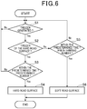
- FIG. 6 is a flow chart depicting a process for road surface decision control. The process for road surface decision control is executed repeatedly in a predetermined control cycle.
- the road surface decision unit 62 first acquires an acceleration from the acceleration sensor 50 and decides whether or not a trigger is generated (step S1).
- step S1 road surface decision unit 62 continues the detection of generation of a trigger.
- step S1 if the trigger is a trigger of the hard road surface H (step S2: Yes), then the road surface decision unit 62 decides whether or not a trigger of the hard road surface H has been generated by a predetermined number of times within a predetermined decision time period after generation of a trigger of the hard road surface H for the first time (step S3).
- step S3 the road surface decision unit 62 decides that the road surface state is the hard road surface H (step S4) and transits to a hard mode.
- the predetermined decision time period is, for example, three seconds (3000 msec)
- the predetermined time number is, for example, 9 times.
- the suspension controlling unit 63 adjusts the motion characteristic of the front forks 18 to that suitable for the hard road surface H through the suspension adjustment mechanism 27.
- step S3 the road surface decision unit 62 resets the trigger and returns the processing to step S1 to continue the detection of generation of a trigger.
- the road surface decision unit 62 decides whether or not a trigger of the soft road surface S has been generated by a predetermined number of times within a predetermined decision time period after generation of a trigger of the soft road surface S for the first time (step S5).
- the road surface decision unit 62 decides that the road surface state is the soft road surface S (step S6) and transits to the soft mode.
- the predetermined decision time period is, for example, three seconds
- the predetermined time number is, for example, 9 times.
- the suspension controlling unit 63 adjusts the motion characteristic of the front forks 18 to that suitable for the soft road surface S through the suspension adjustment mechanism 27.
- step S5 the road surface decision unit 62 resets the trigger and returns the processing to step S1 to continue the detection of generation of a trigger.
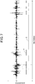
- FIG. 7 is a graph indicative of detection values of the acceleration and a result of the road surface decision.
- the hard road surface H and the soft road surface S were successfully decided on the basis of the acceleration obtained from the acceleration sensor 50 as depicted in FIG. 7 .
- an acceleration higher than that on the soft road surface S is generated.
- FIG. 8 is a graph depicting a damping characteristic of the front forks 18.
- the axis of abscissa indicates the stroke speed of the front forks 18 and the axis of ordinate indicates the damping force.
- the damping force Ten in the elongation direction is greater in increase rate of the damping force with respect to an increase of the stroke speed and higher also in maximum value of the damping force than the damping force Comp in the compression direction. Therefore, in the extension direction, the width of the acceleration occurring with the front forks 18 is greater, and the road surface state is liable to be reflected on the detection value of the acceleration.
- the variation time period ⁇ AB is a period of time required until the acceleration changes from the first threshold value A that is generated upon compression of the front forks 18 to the second threshold value B that is generated upon extension of the front forks 18.
- the variation time period ⁇ AB is a period of time on which both of the acceleration in the compression direction of the front forks 18 and the acceleration in the extension direction of the front forks 18 are reflected.
- the variation time period ⁇ AB includes a detection value in the extension direction of the front forks 18.
- the variation time period ⁇ AB is a period of time upon which the acceleration in the extension direction of the front forks 18 is reflected in this manner, by deciding the road surface state on the basis of the variation time period ⁇ AB, the road surface state can be decided with a high degree of accuracy.
- the motorcycle 1 includes a suspension that supports a front wheel 2 thereon, and a road surface state decision unit 62 that decides a road surface state by detection of an acceleration sensor 50.
- the acceleration sensor 50 is provided at a lower portion of the suspension and is capable of detecting an acceleration at least in a one-axis direction.
- the suspension is a front fork 18 that supports the front wheel 2 of the motorcycle 1.
- the front fork 18 includes a bottom case 30 that connects a lower portion of the front fork 18 and an axle 2a of the front wheel 2 to each other.
- the acceleration sensor 50 is attached to the bottom case 30.
- the acceleration sensor 50 since the acceleration sensor 50 is attached to the bottom case 30 of the front fork 18 of the motorcycle 1, the acceleration sensor 50 can be provided in a simple structure and the acceleration acting upon the front wheel 2 can be detected effectively. Further, the road surface decision unit 62 can decide a state of the road surface with high accuracy from a detection value of the acceleration.
- the road surface state decision unit 62 decides a road surface state on the basis of a detection value in an extension direction of the front fork 18.
- the detection value in the extension direction includes the variation time period ⁇ AB and the second threshold value B. Since the variation amount of the damping force with respect to the stroke of the front fork 18 in the extension direction of the front fork 18 is greater than that in the compression direction of the front fork 18, by deciding the road surface state from the acceleration in the extension direction, the road surface state can be decided with high accuracy.
- the motorcycle 1 includes a front fork 18 that supports a wheel 2 at a lower portion thereof, and a road surface state decision unit 62 that decides a road surface state by detection of an acceleration sensor 50.
- the acceleration sensor 50 is provided at the lower portion of the front fork 18 and is capable of detecting an acceleration at least in a one-axis direction.
- the road surface state decision unit 62 decides a road surface state based on a detection value in an extension direction of the front fork 18.
- the acceleration sensor 50 since the acceleration sensor 50 is attached to the lower portion of the front fork 18, the acceleration sensor 50 can be provided in a simple structure and the acceleration acting upon the front wheel 2 can be detected effectively, and the road surface decision unit 62 can decide a state of the road surface with high accuracy from a detection value of the acceleration. Further, since the variation amount of the damping force with respect to the stroke of the front fork 18 in the extension direction of the front fork 18 is greater than that in the compression direction of the front fork 18, by deciding the road surface state from the acceleration in the extension direction, the road surface state can be decided with high accuracy.
- a brake caliper attachment hole 43c to which a brake caliper 37 for braking the wheel 2 is attached is provided in the bottom case 30, and the acceleration sensor 50 is fastened to the brake caliper attachment hole 43c together with the brake caliper 37. According to the configuration just described, a fixture for exclusive use for attaching the acceleration sensor 50 can be omitted and the number of parts can be reduced.
- the acceleration sensor 50 is disposed between an axle 2a of the wheel 2 and the brake caliper 37 as viewed in side elevation of the vehicle. According to the configuration just described, the acceleration sensor 50 can be provided compactly utilizing the space between the axle 2a and the brake caliper 37, and the acceleration sensor 50 can be prevented from standing out and the appearance is good.
- the road surface state decision unit 62 is capable of deciding a hard road surface H and a soft road surface S that is softer in road surface state than the hard road surface H, and the road surface state decision unit 62 decides that the road surface state is the hard road surface H taking it as a trigger that a variation time period ⁇ AB after an acceleration reaches a first threshold value A until the acceleration reaches a second threshold value B that is lower than the first threshold value A is within a given time period.
- the hard road surface can be decided with high accuracy on the basis of the period of time in which the acceleration drops from the first threshold value A to the second threshold value B.
- the road surface state decision unit 62 decides that the road surface state is the soft road surface S taking it as a trigger that the variation time period ⁇ AB is longer than the given time period. According to the configuration just described, the soft road surface S can be decided with high accuracy on the basis of the period of time in which the acceleration drops from the first threshold value A to the second threshold value B.
- the present second embodiment is different from the first embodiment described hereinabove in that an temporary mode I is provided between the decision of the soft road surface S and the decision of the hard road surface H and that a timer is set for the trigger.
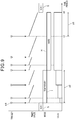
- FIG. 9 is a graph depicting road surface decision of the second embodiment.
- FIG. 9 a relationship among a trigger of the hard road surface H, a timer value of the trigger, a mode for road surface decision and a count of the trigger is depicted.
- the road surface decision unit 62 transits from the soft mode (decision of the soft road surface S) to the temporary mode I.
- the road surface decision unit 62 decides that the road surface state is the hard road surface H, and the suspension controlling unit 63 controls the suspension adjustment mechanism 27 to adjust the motion characteristic of the front forks 18 so as to be suitable for the hard road surface H.
- the road surface decision unit 62 formally decides that the road surface state is the hard road surface H.
- the predetermined decision time period p2 is, for example, one second (1000 msec)
- the predetermined number of times is, for example, three times.
- the count of triggers in the predetermined decision time period p2 is totaling four.
- the road surface decision unit 62 decides that the road surface state is the soft road surface S, and the suspension controlling unit 63 adjusts the motion characteristic of the front forks 18 to that suitable for the soft road surface S. In particular, the road surface decision unit 62 cancels the temporary mode I and returns to decision of the soft road surface S.
- the road surface decision unit 62 resets the count of the timer every time a trigger of the hard road surface H is generated and then starts counting of the timer. If the count of the timer started at time t3 reaches a predetermined value at time t4, then the road surface decision unit 62 decides that the road surface state is the soft road surface S.
- the predetermined time period p3 is a period of time from time t3 to time t4.
- timer counts also in the case where the decision of the hard road surface H in the temporary mode I continues.
- the road surface state decision unit 62 transits to a temporary mode I if the trigger of the hard road surface H is detected. If the trigger of the hard road surface H is detected within a predetermined decision time period p2 after the transition to the temporary mode I, then the road surface state decision unit 62 decides that the road surface state is the hard road surface H, but if the trigger of the hard road surface H is not detected within the predetermined decision time period p2 after the transition to the temporary mode I, then the road surface state decision unit 62 decides that the road surface state is the soft road surface S.
- the road surface state decision unit 62 decides that the road surface state is the hard road surface H. According to the configuration just described, if a trigger tr1 of the hard road surface H is detected, then the road surface decision unit 62 transits to the temporary mode I and, in the temporary mode I, it is decided that the road surface state is the hard road surface H. Therefore, the road surface decision unit 62 can transit rapidly from the decision of the soft road surface S to the decision of the hard road surface H.
- the road surface decision unit 62 returns to the decision for the soft road surface S, and therefore, the road surface decision unit 62 can return to decision of the soft road surface S rapidly in response to an actual road surface state.
- the temporary mode I may be applied to decision of the soft road surface S.
- the road surface state decision unit 62 transits to the temporary mode I if the trigger of the soft road surface S is detected. If the trigger of the soft road surface S is detected within a predetermined decision time period p2 after the transition to the temporary mode I, then the road surface state decision unit 62 decides that the road surface state is the soft road surface S, but if the trigger of the soft road surface S is not detected within the predetermined decision time period p2 after the transition to the temporary mode I, then the road surface state decision unit 62 decides that the road surface state is the hard road surface H. Further, in the temporary mode I, the road surface state decision unit 62 decides that the road surface state is the soft road surface S.
- the road surface state decision unit 62 decides that the road surface state is the soft road surface S. According to the configuration just described, the road surface decision unit 62 can return from the decision of the hard road surface H to the decision of the soft road surface S rapidly, and it can be suppressed that, in the case where the actual road surface state is the soft road surface S, the decision by the road surface decision unit 62 changes to the decision for the hard road surface H.
- the road surface decision unit 62 may decide that the road surface state is the hard road surface H.
- the road surface state decision unit 62 resets a count of a timer and starts counting of the timer, and if the count of the timer reaches a predetermined value, then the road surface state decision unit 62 decides that the road surface state is the soft road surface S. According to the configuration just described, since the decision of the hard road surface is maintained until after the count of the timer reaches the predetermined value, the decision of the hard road surface H can be maintained appropriately.
- the road surface decision unit 62 can return from the decision of the hard road surface H to the decision of the soft road surface S rapidly in response to an actual road surface state.
- the road surface decision unit 62 may reset the count of the timer and start counting of the timer, and when the count reaches the predetermined value, the road surface decision unit 62 may decide that the road surface state is the hard road surface H.
- the motorcycle 1 is taken as an example of the vehicle
- the present invention is not limited to this and can be applied to such vehicles as a three-wheeled saddle riding vehicle having two front wheels or two rear wheels, a saddle riding vehicle including four or more wheels and ordinary four-wheeled vehicles.
- the acceleration sensor 50 may be provided at a portion of a lower portion of a suspension that moves in response to displacement of the wheel.
- a vehicle includes a suspension that supports a front wheel 2 thereon, and a road surface state decision unit that decides a road surface state by detection of an acceleration sensor 50.
- the acceleration sensor 50 is provided at a lower portion of the suspension and is capable of detecting an acceleration at least in a one-axis direction.
- the suspension is a front fork 18 that supports the front wheel 2 of the saddle riding vehicle.
- the front fork 18 includes a bottom case 30 that connects a lower portion of the front fork 18 and an axle 2a of the front wheel 2 to each other.
- the acceleration sensor 50 is attached to the bottom case 30.
Landscapes
- Engineering & Computer Science (AREA)
- Mechanical Engineering (AREA)
- Transportation (AREA)
- Axle Suspensions And Sidecars For Cycles (AREA)
Abstract
Description
- The present invention relates to a vehicle.
- Conventionally, a vehicle is known in which a state of a road surface is decided by an acceleration sensor mounted on the vehicle and a characteristic of a suspension is adjusted on the basis of a result of the decision (for example, refer to Patent Document 1).
- [Patent Document 1]
Japanese Patent Laid-Open No.Hei 10-315733 - Incidentally, it is desired in such a conventional vehicle in which a state of a road surface is decided as described above to make it possible to decide a state of a road surface with a simple structure and with high accuracy.
- The present invention has been made in view of such a situation as described above, and it is an object of the present invention to make it possible for a vehicle to decide a state of a road surface with a simple structure and high accuracy.
- According to a first aspect of the present invention, there is provided a vehicle including a suspension (18) that supports a front wheel (2) thereon, and a road surface state decision unit (62) that decides a road surface state by detection of a sensor (50), in which the sensor (50) is provided at a lower portion of the suspension (18) and is capable of detecting an acceleration at least in a one-axis direction; the suspension (18) is a front fork (18) that supports the front wheel (2) of the vehicle that is a saddle riding vehicle (1); the front fork (18) includes a bottom case (30) that connects a lower portion of the front fork (18) and an axle (2a) of the front wheel (2) to each other; and the sensor (50) is attached to the bottom case (30).
- The vehicle may be configured such that the road surface state decision unit (62) decides a road surface state based on a detection value in an extension direction of the suspension (18).
- According to a second aspect of the present disclosure, there is provided a vehicle including a suspension (18) that supports a wheel (2) at a lower portion thereof, and a road surface state decision unit (62) that decides a road surface state by detection of a sensor (50), in which the sensor (50) is provided at the lower portion of the suspension (18) and is capable of detecting an acceleration at least in a one-axis direction; and the road surface state decision unit (62) decides a road surface state based on a detection value in an extension direction of the suspension (18).
- The vehicle may be configured such that a brake caliper attachment hole (43c) to which a brake caliper (37) for braking the wheel (2) is attached is provided in the bottom case (30), and the sensor (50) is fastened to the brake caliper attachment hole (43c) together with the brake caliper (37).
- Further, the vehicle may be configured such that the sensor (50) is disposed between an axle (2a) of the wheel (2) and the brake caliper (37) as viewed in side elevation of the vehicle.
- Further, the vehicle may be configured such that the road surface state decision unit (62) is capable of deciding a hard road surface (H) and a soft road surface (S) that is softer in road surface state than the hard road surface (H), and the road surface state decision unit (62) decides that the road surface state is the hard road surface (H) taking it as a trigger that a variation time period (ΔAB) after an acceleration reaches a first threshold value (A) until the acceleration reaches a second threshold value (B) that is lower than the first threshold value (A) is within a given time period.
- Further, the vehicle may be configured such that the road surface state decision unit (62) decides that the road surface state is the soft road surface (S) taking it as a trigger that the variation time period (ΔAB) is longer than the given time period.
- Further, the vehicle may be configured such that, where it is decided that the road surface state is the soft road surface (S), the road surface state decision unit (62) transits to a temporary mode (I) if the trigger of the hard road surface (H) is detected; if the trigger of the hard road surface (H) is detected within a second given time period (p2) after the transition to the temporary mode (I), then the road surface state decision unit (62) decides that the road surface state is the hard road surface (H), but if the trigger of the hard road surface (H) is not detected within the second given time period (p2) after the transition to the temporary mode (I), then the road surface state decision unit (62) decides that the road surface state is the soft road surface (S); and, in the temporary mode (I), the road surface state decision unit (62) decides that the road surface state is the hard road surface (H).
- Furthermore, the vehicle may be configured such that, if a third given time period (p3) elapses after the trigger of the hard road surface (H) is detected, then the road surface state decision unit (62) decides that the road surface state is the soft road surface (S).
- Further, the vehicle may be configured such that, where it is decided that the road surface state is the hard road surface (H), every time the trigger of the hard road surface (H) is detected, the road surface state decision unit (62) resets a count of a timer and starts counting of the timer, and if the count of the timer reaches a given value, then the road surface state decision unit (62) decides that the road surface state is the soft road surface (S).
- With the vehicle according to the first aspect of the present invention, it includes a suspension that supports a front wheel thereon, and a road surface state decision unit that decides a road surface state by detection of a sensor. The sensor is provided at a lower portion of the suspension and is capable of detecting an acceleration at least in a one-axis direction. The suspension is a front fork that supports the front wheel of the vehicle that is a saddle riding vehicle. The front fork includes a bottom case that connects a lower portion of the front fork and an axle of the front wheel to each other. The sensor is attached to the bottom case.
- According to the configuration just described, since the sensor for detecting the acceleration is attached to the bottom case of the front fork of the saddle riding vehicle, the sensor can be provided in a simple structure and the acceleration acting on the front wheel can be detected effectively. Further, the road surface state decision unit can decide a state of the road surface with high accuracy from a detection value of the acceleration.
- The road surface state decision unit may decide a road surface state based on a detection value in an extension direction of the suspension. Since, in the extension direction of the suspension, the variation amount of the damping force with respect to a stroke of the suspension is greater than that in the compression direction of the suspension, the road surface state can be decided with high accuracy by deciding the road surface state from the acceleration in the extension direction.
- Meanwhile, with the vehicle according to the second aspect of the present invention, it includes a suspension that supports a wheel at a lower portion thereof, and a road surface state decision unit that decides a road surface state by detection of a sensor. The sensor is provided at the lower portion of the suspension and is capable of detecting an acceleration at least in a one-axis direction. The road surface state decision unit decides a road surface state based on a detection value in an extension direction of the suspension.
- With the configuration described above, since the sensor is attached to the lower portion of the suspension, the sensor can be provided in a simple structure and an acceleration acting on the front wheel can be detected effectively. Further, the road surface state decision unit can decide a state of the road surface with high accuracy from the detection value of the acceleration. Further, since, in the extension direction of the suspension, the variation amount of the damping force with respect to a stroke of the suspension is greater than that in the compression direction of the suspension, the road surface state can be decided with high accuracy by deciding the road surface state from the acceleration in the extension direction.
- Further, in the vehicle, a brake caliper attachment hole to which a brake caliper for braking the wheel is attached may be provided in the bottom case, and the sensor may be fastened to the brake caliper attachment hole together with the brake caliper. With the configuration just described, a fixture for exclusive use for attachment of the sensor can be omitted and the number of parts can be reduced.
- Furthermore, in the vehicle, the sensor may be disposed between an axle of the wheel and the brake caliper as viewed in side elevation of the vehicle. With the configuration just described, the sensor can be provided compactly utilizing a space between the axle and the brake caliper and the sensor can be prevented from standing out, and therefore, the appearance performance is good.
- Further, in the vehicle, the road surface state decision unit may be capable of deciding a hard road surface and a soft road surface that is softer in road surface state than the hard road surface. Further, the road surface state decision unit may decide that the road surface state is the hard road surface taking it as a trigger that a variation time period after an acceleration reaches a first threshold value until the acceleration reaches a second threshold value that is lower than the first threshold value is within a given time period.
- With the configuration just described, the hard road surface can be decided with high accuracy on the basis of a time period until after the acceleration decreases from the first threshold value to the second threshold value.
- Further, in the vehicle, the road surface state decision unit may decide that the road surface state is the soft road surface taking it as a trigger that the variation time period is longer than the given time period.
- With the configuration described above, the soft road surface can be decided with high accuracy on the basis of a time period until after the acceleration decreases from the first threshold value to the second threshold value.
- Further, in the vehicle, where it is decided that the road surface state is the soft road surface, the road surface state decision unit may transit to a temporary mode if the trigger of the hard road surface is detected. Then, if the trigger of the hard road surface is detected within a second given time period after the transition to the temporary mode, then the road surface state decision unit may decide that the road surface state is the hard road surface, but if the trigger of the hard road surface is not detected within the second given time period after the transition to the temporary mode, then the road surface state decision unit may decide that the road surface state is the soft road surface. Further, in the temporary mode, the road surface state decision unit may decide that the road surface state is the hard road surface.
- With the configuration described above, if the trigger of the hard road surface is detected, then since the road surface state decision unit transits to the temporary mode and decides that the road surface state is the hard road surface, the road surface state decision unit can quickly transit from the decision of the soft road surface to the decision of the hard road surface. On the other hand, if the trigger of the hard road surface is not detected within the second given time period after migration to the temporary mode, then since the road surface state decision unit quickly returns to the decision of the soft road surface, the road surface state decision unit can return to the decision of the soft road surface in response to the actual road surface state.
- Furthermore, in the he vehicle, if a third given time period elapses after the trigger of the hard road surface is detected, then the road surface state decision unit may decide that the road surface state is the soft road surface. With the configuration just described, the road surface state decision unit can quickly return from the decision of the hard road surface to the decision of the soft road surface, and where the actual road surface state is the soft road surface, transition to the decision of the hard road surface is suppressed.
- Further, in the vehicle, where it is decided that the road surface state is the hard road surface, every time the trigger of the hard road surface is detected, the road surface state decision unit may reset a count of a timer and starts counting of the timer, and if the count of the timer reaches a given value, then the road surface state decision unit may decide that the road surface state is the soft road surface.
- With the configuration just described, since the decision of the hard road surface is maintained until after the count of the timer reaches the given value, the decision of the hard road surface can be maintained appropriately. Further, if the count of the timer reaches a given value, then since it is decided that the road surface state is the soft road surface, the road surface state decision unit can quickly return from the decision of the hard road surface to the decision of the soft road surface.
-
-
FIG. 1 is a right side elevational view of a motorcycle according to a first embodiment of the present invention. -
FIG. 2 is a left side elevational view of peripheral elements of a lower portion of a front fork. -
FIG. 3 is a perspective view of the lower portion of a front fork on the left side as viewed from the rear side. -
FIG. 4 is a block diagram of a configuration that decides a road surface state from an acceleration. -
FIG. 5 is a view depicting a waveform of an acceleration detected by an acceleration sensor. -
FIG. 6 is a flow chart depicting a process of road surface decision control. -
FIG. 7 is a graph depicting detection values of the acceleration and a result of road surface decision. -
FIG. 8 is a graph depicting a damping characteristic of the front fork. -
FIG. 9 is a graph depicting road surface decision of a second embodiment. - In the following, embodiments of the present invention are described with reference to the drawings. It is to be noted that, unless otherwise specified, directions such as forward, rearward, leftward, rightward, upward and downward directions in the following description are same as those of a vehicle body described below. Further, reference character FR depicted in the drawings indicates the forward direction of the vehicle body, reference character UP indicates the upward direction of the vehicle body, and reference character LH indicates the leftward direction of the vehicle body.
-
FIG. 1 is a right side elevational view of amotorcycle 1 according to a first embodiment of the present invention. It is to be noted that, inFIG. 1 , where elements are provided in left and right pair, only an element on the right side is depicted including a reference character therefor. - The
motorcycle 1 is a vehicle in which anengine 10 as a power unit is supported on a vehicle body frame F, and asteering system 11 for supporting a front wheel 2 (vehicle wheel) for steering movement is supported for steering movement at a front end of the vehicle body frame F and aswing arm 12 that supports arear wheel 3 is provided at a rear portion of the vehicle body frame F. - The
motorcycle 1 is a saddle riding vehicle in which aseat 13 on which the driver is to be seated astride is provided above a rear portion of the vehicle body frame F. - The
steering system 11 is supported on ahead pipe 15 provided at a front end of the vehicle body frame F. - The
steering system 11 includes a steering shaft (not depicted) supported for rotation on thehead pipe 15, atop bridge 16 fixed to an upper end of the steering shaft, abottom bridge 17 fixed to a lower end of the steering shaft, and a front fork having front forks 18 (suspensions) disposed in pair on the left and right sides of thehead pipe 15 and supported on thetop bridge 16 and thebottom bridge 17. - An
axle 2a is supported at a lower end portion of thefront forks 18 provided in pair on the left and right sides. Thefront wheel 2 is disposed between the left and rightfront forks 18 and is supported on theaxle 2a. - A
handlebar 19 that is used for steering of thefront wheel 2 by the driver is attached to thetop bridge 16. - A
front fender 20 is attached to thebottom bridge 17 such that it covers thefront wheel 2 from above. - The
swing arm 12 is supported at a front end portion thereof on apivot shaft 21 provided at a rear portion of the vehicle body frame F such that theswing arm 12 rocks upwardly and downwardly around thepivot shaft 21. - A
rear suspension 22 is stretched between the front end of theswing arm 12 and the vehicle body frame F. - Driving force of the
engine 10 is transmitted to therear wheel 3 through achain 23. -
FIG. 2 is a left side elevational view of peripheral elements of a lower portion of thefront fork 18.FIG. 3 is a perspective view of the lower portion of the left sidefront fork 18 of the front fork as viewed from the rear side. - Referring to
FIGS. 1 to 3 , thefront forks 18 are disposed in a posture inclined rearwardly with respect to the vertical direction as viewed in side elevation of the vehicle. - Each of the
front forks 18 of the front fork includes a fixedtube 25 fixed to thetop bridge 16 and thebottom bridge 17, amovable tube 26 that strokes in an axial direction with respect to the fixingtube 25, a coil spring (not depicted) that is provided in the tube and is compressed in a stroke direction of thefront fork 18, a damping force generation unit (not depicted), and a suspension adjustment mechanism 27 (FIG. 4 ) that adjusts a behavior characteristic of thefront fork 18. - The
front fork 18 is a telescopic suspension in which themovable tube 26 strokes in an axial direction with respect to the fixedtube 25. - The coil spring described above biases the
front fork 18 in its extension direction and absorbs a shock from the road surface. - The damping force generation unit damps vibration of the
front fork 18 in its contraction direction and extension direction. The damping force generation unit damps the stroke (vibration) of thefront fork 18 by the resistance of the hydraulic oil in thefront fork 18. - The
suspension adjustment mechanism 27 is driven by an actuator and can change the initial load of the coil spring of thefront fork 18 and the damping force of thefront fork 18. - The
movable tube 26 includes a tubemain body 29 that fits from below and slidably moves in the fixedtube 25, and abottom case 30 coupled to a lower end portion of the tubemain body 29. - The
front wheel 2 is disposed between the left and rightbottom cases 30. Thefront wheel 2 is supported for rotation on theaxle 2a extending between the left and rightbottom cases 30. - The
front wheel 2 includes atire 31 and awheel 32 to which thetire 31 is attached. - The
wheel 32 includes anannular rim 33 to which thetire 31 is attached, ahub 34 supported for rotation on theaxle 2a, and spokes (not depicted) that connect thehub 34 and therim 33 to each other. - The
hub 34 is formed in a circular shape as viewed in side elevation and has, at the center thereof, an axle hole in which theaxle 2a is fitted. - The spokes extend radially to the diametrically outer sides from an outer circumference of the
hub 34 and are coupled to an inner circumference of therim 33. - The
motorcycle 1 includes afront brake system 35 for braking thefront wheel 2. - The
front brake system 35 includes abrake disk 36 that rotates together with thefront wheel 2, abrake caliper 37 that sandwiches and presses thebrake disk 36 under hydraulic pressure to brake thefront wheel 2, and abrake hose 38 that supplies hydraulic pressure to thebrake caliper 37 therethrough. - The
brake disk 36 is disposed coaxially with theaxle 2a and fixed to thehub 34. Thebrake disk 36 is disposed between the left sidefront fork 18 and thewheel 32 in the vehicle widthwise direction. - The
brake caliper 37 is fixed to the left sidebottom case 30. - The
brake caliper 37 is disposed behind theaxle 2a and thebottom case 30 as viewed in side elevation of the vehicle. - The
brake caliper 37 includes acaliper supporting member 39 fixed to thebottom case 30, and a calipermain body 40 that sandwiches and presses thebrake disk 36 through a brake pad (not detected). - The
brake caliper 37 is fixed to thebottom case 30 bycaliper fixation bolts caliper supporting member 39, respectively. - The caliper
main body 40 is supported at a rear portion of thecaliper supporting member 39. Thebrake hose 38 is led out from a rear portion of the calipermain body 40 and extends upwardly. - The
bottom case 30 includes a bottom casemain body 42 coupled to a lower end portion of the tubemain body 29, and caliper stays 43a and 43b extending rearwardly from a rear face of the bottom casemain body 42. - The bottom case
main body 42 has, at a lower portion of a front portion thereof as viewed in side elevation of the vehicle, anaxle supporting hole 44 that supports theaxle 2a. - A
wheel speed sensor 45 is attached to an upper portion of a front portion of the bottom casemain body 42. Thewheel speed sensor 45 detects rotation of thefront wheel 2 by detecting a ring-shapedpulser rotor 46 attached to thehub 34. - The
axle 2a and thewheel speed sensor 45 are positioned forwardly of theaxial line 18a of thefront fork 18. Acable 45a of thewheel speed sensor 45 extends rearwardly along an outer side face of the bottom casemain body 42 and routed upwardly along thebrake hose 38. Thecable 45a is connected to a control unit 55 (FIG. 4 ). - A
fork cover 47 is fastened at a lower end portion thereof to an upper portion of the bottom casemain body 42. The fork cover 47 covers the tubemain body 29 from the front and from the sides. - The caliper stays 43a and 43b are provided in pair on the upper and lower sides, respectively. The
caliper stay 43a on the upper side extends rearwardly from an upper end portion of a rear face of the bottom casemain body 42. Thecaliper stay 43b on the lower side extends rearwardly downwards from a lower end portion of the rear face of the bottom casemain body 42. - At a rear end portion of the caliper stays 43a and 43b, attachment holes 43c (brake caliper attachment holes) are provided which extend in the vehicle widthwise direction through the caliper stays 43a and 43b.
- The caliper stays 43a and 43b are positioned rearwardly of the
axial line 18a of thefront fork 18. - The
caliper supporting member 39 is fastened to inner side faces in the vehicle widthwise direction of the caliper stays 43a and 43b by thecaliper fixation bolts - The
motorcycle 1 includes an acceleration sensor 50 (sensor) for detecting the acceleration acting on themotorcycle 1. Theacceleration sensor 50 is attached to thebottom case 30 of themovable tube 26 of the left sidefront fork 18. - When the
motorcycle 1 runs on the road surface, thefront forks 18 stroke in response to a road surface condition such as recesses and projections or the like of the road surface, a movement of the center of gravity or the like caused by acceleration and deceleration of themotorcycle 1. - In particular, in each
front fork 18, themovable tube 26 strokes in an axial direction of theaxial line 18a together with thefront wheel 2 with respect to the fixedtube 25 fixed to the vehicle body side. - The
acceleration sensor 50 attached to thebottom case 30 of themovable tube 26 moves integrally with themovable tube 26 and detects an acceleration when themovable tube 26 strokes. - Here, the
acceleration sensor 50 is capable of detecting an acceleration in a one-axis direction and detects an acceleration of a stroke in the axial direction of thefront fork 18. However, the acceleration sensor is sufficient if it can detect an acceleration in at least a one-axis direction and may be capable of detecting accelerations in a plurality of directions. - The
acceleration sensor 50 includes abracket portion 51 fixed to thebottom case 30, and a sensormain body portion 52 having a device for detecting an acceleration. - The
bracket portion 51 is a plate-shaped member elongated upwardly and downwardly as viewed in side elevation of the vehicle and is fixed to the caliper stays 43a and 43b. At an upper end portion of thebracket portion 51, afixation hole 51a is provided such that thecaliper fixation bolt 41a on the upper side is fitted in thefixation hole 51a. At a lower end of thebracket portion 51, afixation hole 51b is provided such that thecaliper fixation bolt 41b on the lower side is fitted in thefixation hole 51b. - The sensor
main body portion 52 is fixed to an inner side face in the vehicle widthwise direction of thebracket portion 51 and is disposed, in the vehicle widthwise direction, between thebracket portion 51 and thecaliper supporting member 39. Further, the sensormain body portion 52 is positioned, in the upward and downward direction, between thecaliper stay 43a on the upper side and thecaliper stay 43b on the lower side. - A
harness 53 led out from an upper portion of the sensormain body portion 52 extends rearwardly upwards toward thebrake hose 38 side and is laid toward the vehicle body side above along thebrake hose 38. - The
acceleration sensor 50 is fastened, at thebracket portion 51 thereof disposed on an outer side face in the vehicle widthwise direction of the caliper stays 43a and 43b, to the caliper stays 43a and 43b by thecaliper fixation bolts fixation holes - In particular, the
acceleration sensor 50 is fastened to the caliper stays 43a and 43b together with thebrake caliper 37 by thecaliper fixation bolts - In side elevation of the vehicle, the
acceleration sensor 50 is positioned rearwardly of theaxle 2a but forwardly of the calipermain body 40 and is disposed between theaxle 2a and the calipermain body 40. - The
motorcycle 1 detects the acceleration of the stroke of thefront forks 18 by theacceleration sensor 50 and decides the road surface condition of the road surface on which themotorcycle 1 runs from a result of the detection. -
FIG. 4 is a block diagram of a configuration for deciding the road surface condition from an acceleration. - The
motorcycle 1 includes acontrol unit 55 that controls the components of themotorcycle 1 such as theengine 10. Thecontrol unit 55 is an electronic control unit (ECU) and is attached to the vehicle body. - The
control unit 55 includes an arithmetic operation unit (not depicted) and astorage unit 56. The arithmetic operation unit is a processor such as a CPU. Thecontrol unit 55 executes a program stored in thestorage unit 56 to perform control of theengine 10 and so forth and decision of the road surface state. Thestorage unit 56 is a nonvolatile storage device such as a flash ROM or an EEPROM and stores a program to be executed by the arithmetic operation unit and data and so forth to be processed by the arithmetic operation unit. - To the
control unit 55, theacceleration sensor 50 is connected through theharness 53. Further, to thecontrol unit 55, thesuspension adjustment mechanism 27 and thewheel speed sensor 45 are connected. - Various functional units the
control unit 55 has are formed by cooperation with software and hardware when the arithmetic operation unit executes a program. - The
control unit 55 includes such functional units as a vehiclespeed detection unit 60, anacceleration detection unit 61, a road surface decision unit 62 (road surface state decision means) and asuspension controlling unit 63. - A vehicle
speed detection unit 60 detects a vehicle speed of themotorcycle 1 on the basis of detection information of thewheel speed sensor 45. - The
acceleration detection unit 61 detects an acceleration of a stroke of themovable tube 26 of thefront fork 18 on the basis of detection information of theacceleration sensor 50. - The road
surface decision unit 62 performs a process for road surface state decision control for deciding a road surface state from an acceleration of a stroke of thefront fork 18. - The
suspension controlling unit 63 controls thesuspension adjustment mechanism 27 on the basis of the vehicle speed of themotorcycle 1 and information of the road surface state and so forth to adjust the behavior characteristic of thefront forks 18. -
FIG. 5 is a view depicting a waveform of the acceleration detected by theacceleration sensor 50. InFIG. 5 , time is indicated by the axis of abscissa, and the acceleration is indicated by the axis of ordinate. - In
FIG. 5 , upon running of themotorcycle 1, a waveform W1 and another waveform W2 of accelerations when thefront forks 18 are extended after compressed are indicated in the proximity of time t1 and in the proximity of time t2, respectively. The waveform W1 and the waveform W2 inFIG. 5 project downwardly from the proximity of a base line. - In the waveform W1, the acceleration indicates a maximum value at time t1. A portion of the waveform W1 before time t1 indicates an acceleration in a state in which the
front forks 18 are compressed. A portion of the waveform W1 after time t1 indicates an acceleration in a state in which thefront forks 18 are extended. - In the waveform W2, the acceleration indicates a maximum value at time t2. A portion of the waveform W2 before time t2 indicates an acceleration in a state in which the
front forks 18 are compressed. A portion of the waveform W2 after time t2 indicates an acceleration in a state in which thefront forks 18 are extended. - It is to be noted that, while, in
FIG. 5 , in regard to the acceleration, the positive direction of the axis of ordinate is a compression direction and the negative direction of the axis of ordinate is an elongation direction, the present invention is not limited to this. For example, theacceleration sensor 50 may be attached in the reverse direction to that in the case ofFIG. 5 such that the positive direction of the axis of ordinate indicates an elongation direction and the negative direction of the axis of ordinate indicates a compression direction. - The road
surface decision unit 62 uses, for the decision of a road surface state, a first threshold value A of the acceleration, a second threshold value B of the acceleration and a variation time period ΔAB are used. - The first threshold value A is a threshold value set for the acceleration when the
front forks 18 are compressed. Therefore, in the waveform W1, the acceleration reaches the first threshold value A beforetime 51, but in the waveform W2, the acceleration reaches the first threshold value A before time t2. - The second threshold value B is a threshold value set for the acceleration when the
front forks 18 are extended after they are compressed. Therefore, in the waveform W1, the acceleration reaches the second threshold value B after time t1, but in the waveform W2, the acceleration reaches the second threshold value B after time t2. The second threshold value B is a value lower than the first threshold value A. - The variation time period ΔAB is a period of time in which the acceleration varies from the first threshold value A to the second threshold value B.
- The road
surface decision unit 62 decides, as a road surface state, a hard road surface H (first road state, refer toFIG. 7 ) and a soft road surface S (second road state, refer toFIG. 7 ) whose road surface state is softer than that of the hard road surface H. For example, although the hard road surface H is a road surface of hard soil, it may include a road surface of a paved road. The soft road surface S is a comparatively soft road surface, for example, like that of the sand of a desert or that of muddy ground. - The inventors of the present application have acquired such knowledge by performing test running of the
motorcycle 1 that the variation time period ΔAB differs much between the hard road surface H and the soft road surface S. In particular, on the soft road surface S, the movement of thefront forks 18 is slower than that on the hard road surface H, and on the soft road surface S, the variation time period ΔAB is longer than that on the hard road surface H. The roadsurface decision unit 62 in the present first embodiment decides the hard road surface H and the soft road surface S from the variation time period ΔAB. - The road
surface decision unit 62 generates, in a process for road surface decision control, a trigger (event) for road surface decision with reference to whether or not the variation time period ΔAB is within a predetermined time period p (not depicted). The predetermined time period p is, for example, 50 msec. - More particularly, in the case where the variation time period ΔAB is within the predetermined time period p, the road
surface decision unit 62 generates a trigger of the hard road surface H. The roadsurface decision unit 62 counts the number of times of generation of a trigger of the hard road surface H. - In the case where the variation time period ΔAB is not within the predetermined time period p, namely, in the case where the variation time period ΔAB is longer than the predetermined time period p, the road
surface decision unit 62 generates a trigger of the soft road surface S. The roadsurface decision unit 62 counts the number of times of generation of a trigger of the soft road surface S. -
FIG. 6 is a flow chart depicting a process for road surface decision control. The process for road surface decision control is executed repeatedly in a predetermined control cycle. - In the road surface decision control, the road
surface decision unit 62 first acquires an acceleration from theacceleration sensor 50 and decides whether or not a trigger is generated (step S1). - In the case where a trigger is not generated (step S1: No), road
surface decision unit 62 continues the detection of generation of a trigger. - On the other hand, in the case where a trigger is generated (step S1: Yes), if the trigger is a trigger of the hard road surface H (step S2: Yes), then the road
surface decision unit 62 decides whether or not a trigger of the hard road surface H has been generated by a predetermined number of times within a predetermined decision time period after generation of a trigger of the hard road surface H for the first time (step S3). In the case where a trigger of the hard road surface H has been generated by the predetermined number of times within the predetermined decision time period after generation of a trigger of the hard road surface H for the first time (step S3: Yes), the roadsurface decision unit 62 decides that the road surface state is the hard road surface H (step S4) and transits to a hard mode. Here, the predetermined decision time period is, for example, three seconds (3000 msec), and the predetermined time number is, for example, 9 times. - In the hard mode, the
suspension controlling unit 63 adjusts the motion characteristic of thefront forks 18 to that suitable for the hard road surface H through thesuspension adjustment mechanism 27. - In the case where a trigger of the hard road surface H has not been generated by the predetermined number of times within the predetermined decision time period after generation of a trigger of the hard road surface H for the first time (step S3: No), the road
surface decision unit 62 resets the trigger and returns the processing to step S1 to continue the detection of generation of a trigger. - In the case where the detected trigger is not a trigger of the hard road surface H (step S2: No), namely, in the case where the detected trigger is a trigger of the soft road surface S, the road
surface decision unit 62 decides whether or not a trigger of the soft road surface S has been generated by a predetermined number of times within a predetermined decision time period after generation of a trigger of the soft road surface S for the first time (step S5). - In the case where a trigger of the soft road surface S has been generated by the predetermined number of times within the predetermined decision time period after generation of a trigger of the soft road surface S for the first time (step S5: Yes), the road
surface decision unit 62 decides that the road surface state is the soft road surface S (step S6) and transits to the soft mode. Here, the predetermined decision time period is, for example, three seconds, and the predetermined time number is, for example, 9 times. - In the soft mode described above, the
suspension controlling unit 63 adjusts the motion characteristic of thefront forks 18 to that suitable for the soft road surface S through thesuspension adjustment mechanism 27. - In the case where a trigger of the soft road surface S has not been generated by the predetermined number of times within the predetermined decision time period after generation of a trigger of the soft road surface S for the first time (step S5: No), the road
surface decision unit 62 resets the trigger and returns the processing to step S1 to continue the detection of generation of a trigger. -
FIG. 7 is a graph indicative of detection values of the acceleration and a result of the road surface decision. - By the road surface decision control, the hard road surface H and the soft road surface S were successfully decided on the basis of the acceleration obtained from the
acceleration sensor 50 as depicted inFIG. 7 . On the hard road surface H, an acceleration higher than that on the soft road surface S is generated. -
FIG. 8 is a graph depicting a damping characteristic of thefront forks 18. - In
FIG. 8 , the axis of abscissa indicates the stroke speed of thefront forks 18 and the axis of ordinate indicates the damping force. - The damping force Ten in the elongation direction is greater in increase rate of the damping force with respect to an increase of the stroke speed and higher also in maximum value of the damping force than the damping force Comp in the compression direction. Therefore, in the extension direction, the width of the acceleration occurring with the
front forks 18 is greater, and the road surface state is liable to be reflected on the detection value of the acceleration. - In the present first embodiment, the variation time period ΔAB is a period of time required until the acceleration changes from the first threshold value A that is generated upon compression of the
front forks 18 to the second threshold value B that is generated upon extension of thefront forks 18. In other words, the variation time period ΔAB is a period of time on which both of the acceleration in the compression direction of thefront forks 18 and the acceleration in the extension direction of thefront forks 18 are reflected. The variation time period ΔAB includes a detection value in the extension direction of thefront forks 18. Since the variation time period ΔAB is a period of time upon which the acceleration in the extension direction of thefront forks 18 is reflected in this manner, by deciding the road surface state on the basis of the variation time period ΔAB, the road surface state can be decided with a high degree of accuracy. - As described above, according to the first embodiment to which the present invention is applied, the
motorcycle 1 includes a suspension that supports afront wheel 2 thereon, and a road surfacestate decision unit 62 that decides a road surface state by detection of anacceleration sensor 50. Theacceleration sensor 50 is provided at a lower portion of the suspension and is capable of detecting an acceleration at least in a one-axis direction. The suspension is afront fork 18 that supports thefront wheel 2 of themotorcycle 1. Thefront fork 18 includes abottom case 30 that connects a lower portion of thefront fork 18 and anaxle 2a of thefront wheel 2 to each other. Theacceleration sensor 50 is attached to thebottom case 30. - According to the configuration just described, since the
acceleration sensor 50 is attached to thebottom case 30 of thefront fork 18 of themotorcycle 1, theacceleration sensor 50 can be provided in a simple structure and the acceleration acting upon thefront wheel 2 can be detected effectively. Further, the roadsurface decision unit 62 can decide a state of the road surface with high accuracy from a detection value of the acceleration. - Further, the road surface
state decision unit 62 decides a road surface state on the basis of a detection value in an extension direction of thefront fork 18. Here, the detection value in the extension direction includes the variation time period ΔAB and the second threshold value B. Since the variation amount of the damping force with respect to the stroke of thefront fork 18 in the extension direction of thefront fork 18 is greater than that in the compression direction of thefront fork 18, by deciding the road surface state from the acceleration in the extension direction, the road surface state can be decided with high accuracy. - Meanwhile, the
motorcycle 1 includes afront fork 18 that supports awheel 2 at a lower portion thereof, and a road surfacestate decision unit 62 that decides a road surface state by detection of anacceleration sensor 50. Theacceleration sensor 50 is provided at the lower portion of thefront fork 18 and is capable of detecting an acceleration at least in a one-axis direction. The road surfacestate decision unit 62 decides a road surface state based on a detection value in an extension direction of thefront fork 18. - According to the configuration just described, since the
acceleration sensor 50 is attached to the lower portion of thefront fork 18, theacceleration sensor 50 can be provided in a simple structure and the acceleration acting upon thefront wheel 2 can be detected effectively, and the roadsurface decision unit 62 can decide a state of the road surface with high accuracy from a detection value of the acceleration. Further, since the variation amount of the damping force with respect to the stroke of thefront fork 18 in the extension direction of thefront fork 18 is greater than that in the compression direction of thefront fork 18, by deciding the road surface state from the acceleration in the extension direction, the road surface state can be decided with high accuracy. - Further, a brake
caliper attachment hole 43c to which abrake caliper 37 for braking thewheel 2 is attached is provided in thebottom case 30, and theacceleration sensor 50 is fastened to the brakecaliper attachment hole 43c together with thebrake caliper 37. According to the configuration just described, a fixture for exclusive use for attaching theacceleration sensor 50 can be omitted and the number of parts can be reduced. - Furthermore, the
acceleration sensor 50 is disposed between anaxle 2a of thewheel 2 and thebrake caliper 37 as viewed in side elevation of the vehicle. According to the configuration just described, theacceleration sensor 50 can be provided compactly utilizing the space between theaxle 2a and thebrake caliper 37, and theacceleration sensor 50 can be prevented from standing out and the appearance is good. - Further, the road surface
state decision unit 62 is capable of deciding a hard road surface H and a soft road surface S that is softer in road surface state than the hard road surface H, and the road surfacestate decision unit 62 decides that the road surface state is the hard road surface H taking it as a trigger that a variation time period ΔAB after an acceleration reaches a first threshold value A until the acceleration reaches a second threshold value B that is lower than the first threshold value A is within a given time period. - According to the configuration just described, the hard road surface can be decided with high accuracy on the basis of the period of time in which the acceleration drops from the first threshold value A to the second threshold value B.
- Further, the road surface
state decision unit 62 decides that the road surface state is the soft road surface S taking it as a trigger that the variation time period ΔAB is longer than the given time period. According to the configuration just described, the soft road surface S can be decided with high accuracy on the basis of the period of time in which the acceleration drops from the first threshold value A to the second threshold value B. - In the following, a second embodiment to which the present invention is applied is described with reference to
FIG. 9 . In the present second embodiment, like elements to those in the first embodiment described hereinabove are denoted by like reference characters, and overlapping description of them is omitted herein. - The present second embodiment is different from the first embodiment described hereinabove in that an temporary mode I is provided between the decision of the soft road surface S and the decision of the hard road surface H and that a timer is set for the trigger.
-
FIG. 9 is a graph depicting road surface decision of the second embodiment. - In
FIG. 9 , a relationship among a trigger of the hard road surface H, a timer value of the trigger, a mode for road surface decision and a count of the trigger is depicted. - When it is decided that the road surface state is the soft road surface S, if a trigger tr1 of the hard road face for the first time is generated, then the road
surface decision unit 62 transits from the soft mode (decision of the soft road surface S) to the temporary mode I. In the temporary mode I, the roadsurface decision unit 62 decides that the road surface state is the hard road surface H, and thesuspension controlling unit 63 controls thesuspension adjustment mechanism 27 to adjust the motion characteristic of thefront forks 18 so as to be suitable for the hard road surface H. - In the case where a trigger of the hard road surface H is generated by a predetermined number of times in a predetermined decision time period p2 (second predetermined time period) after generation of a trigger tr1 of the soft road surface S for the first time, the road
surface decision unit 62 formally decides that the road surface state is the hard road surface H. Here, the predetermined decision time period p2 is, for example, one second (1000 msec), and the predetermined number of times is, for example, three times. InFIG. 9 , the count of triggers in the predetermined decision time period p2 is totaling four. - In the case where a trigger of the hard road surface H is generated by a predetermined number of times in the predetermined decision time period p2 after generation of the trigger tr1 of the soft road surface S for the first time, the road
surface decision unit 62 decides that the road surface state is the soft road surface S, and thesuspension controlling unit 63 adjusts the motion characteristic of thefront forks 18 to that suitable for the soft road surface S. In particular, the roadsurface decision unit 62 cancels the temporary mode I and returns to decision of the soft road surface S. - Further, in the case where it is decided that the road surface state is the hard road surface H, the road
surface decision unit 62 resets the count of the timer every time a trigger of the hard road surface H is generated and then starts counting of the timer. If the count of the timer started at time t3 reaches a predetermined value at time t4, then the roadsurface decision unit 62 decides that the road surface state is the soft road surface S. - In particular, if a predetermined time period p3 elapses while a next trigger of the hard road surface H is not generated in the predetermined time period p3 (third predetermined time period) after a trigger of the hard road surface H is generated, then it is decided that the road surface state is the soft road surface S. The predetermined time period p3 is a period of time from time t3 to time t4.
- It is to be noted that the timer counts also in the case where the decision of the hard road surface H in the temporary mode I continues.
- As described above, according to the second embodiment to which the present invention is applied, where it is decided that the road surface state is the soft road surface S, the road surface
state decision unit 62 transits to a temporary mode I if the trigger of the hard road surface H is detected. If the trigger of the hard road surface H is detected within a predetermined decision time period p2 after the transition to the temporary mode I, then the road surface state decision unit 62 decides that the road surface state is the hard road surface H, but if the trigger of the hard road surface H is not detected within the predetermined decision time period p2 after the transition to the temporary mode I, then the road surface state decision unit 62 decides that the road surface state is the soft road surface S. Further, in the temporary mode I, the road surface state decision unit 62 decides that the road surface state is the hard road surface H. According to the configuration just described, if a trigger tr1 of the hard road surface H is detected, then the road surface decision unit 62 transits to the temporary mode I and, in the temporary mode I, it is decided that the road surface state is the hard road surface H. Therefore, the road surface decision unit 62 can transit rapidly from the decision of the soft road surface S to the decision of the hard road surface H. Then, if a trigger of the hard road surface H is not detected in the predetermined decision time period p2 after the transition to the temporary mode I, then the road surface decision unit 62 returns to the decision for the soft road surface S, and therefore, the road surface decision unit 62 can return to decision of the soft road surface S rapidly in response to an actual road surface state. - It is to be noted that the temporary mode I may be applied to decision of the soft road surface S. In particular, where it is decided that the road surface state is the hard road surface H, the road surface
state decision unit 62 transits to the temporary mode I if the trigger of the soft road surface S is detected. If the trigger of the soft road surface S is detected within a predetermined decision time period p2 after the transition to the temporary mode I, then the road surfacestate decision unit 62 decides that the road surface state is the soft road surface S, but if the trigger of the soft road surface S is not detected within the predetermined decision time period p2 after the transition to the temporary mode I, then the road surfacestate decision unit 62 decides that the road surface state is the hard road surface H. Further, in the temporary mode I, the road surfacestate decision unit 62 decides that the road surface state is the soft road surface S. - Furthermore, if a third given time period p3 elapses after the trigger of the hard road surface H is detected, then the road surface
state decision unit 62 decides that the road surface state is the soft road surface S. According to the configuration just described, the roadsurface decision unit 62 can return from the decision of the hard road surface H to the decision of the soft road surface S rapidly, and it can be suppressed that, in the case where the actual road surface state is the soft road surface S, the decision by the roadsurface decision unit 62 changes to the decision for the hard road surface H. - It is to be noted that, if, in the case where it is decided that the road surface state is the soft road surface S, the predetermined time period p3 elapses after a trigger of the soft road surface S is detected, then the road
surface decision unit 62 may decide that the road surface state is the hard road surface H. - Further, where it is decided that the road surface state is the hard road surface H, every time the trigger of the hard road surface H is detected, the road surface
state decision unit 62 resets a count of a timer and starts counting of the timer, and if the count of the timer reaches a predetermined value, then the road surfacestate decision unit 62 decides that the road surface state is the soft road surface S. According to the configuration just described, since the decision of the hard road surface is maintained until after the count of the timer reaches the predetermined value, the decision of the hard road surface H can be maintained appropriately. Further, since, if the count of the timer reaches the predetermined value, then it is decided that the road surface state is the soft road surface S, the roadsurface decision unit 62 can return from the decision of the hard road surface H to the decision of the soft road surface S rapidly in response to an actual road surface state. - It is to be noted that, in the case where it is decided that the road surface state is the soft road surface S, every time a trigger of the soft road surface S is detected, the road
surface decision unit 62 may reset the count of the timer and start counting of the timer, and when the count reaches the predetermined value, the roadsurface decision unit 62 may decide that the road surface state is the hard road surface H. - It is to be noted that the embodiments described above indicates a mode to which the present invention is applied, and the present invention is not limited to the first and second embodiments.
- Although, in the foregoing description of the first and second embodiment, the
motorcycle 1 is taken as an example of the vehicle, the present invention is not limited to this and can be applied to such vehicles as a three-wheeled saddle riding vehicle having two front wheels or two rear wheels, a saddle riding vehicle including four or more wheels and ordinary four-wheeled vehicles. In the case where the present invention is applied to vehicles such as four-wheeled vehicles, theacceleration sensor 50 may be provided at a portion of a lower portion of a suspension that moves in response to displacement of the wheel. - To make it possible for a vehicle to decide a state of a road surface with a simple structure and high accuracy.
- A vehicle includes a suspension that supports a
front wheel 2 thereon, and a road surface state decision unit that decides a road surface state by detection of anacceleration sensor 50. Theacceleration sensor 50 is provided at a lower portion of the suspension and is capable of detecting an acceleration at least in a one-axis direction. The suspension is afront fork 18 that supports thefront wheel 2 of the saddle riding vehicle. Thefront fork 18 includes abottom case 30 that connects a lower portion of thefront fork 18 and anaxle 2a of thefront wheel 2 to each other. Theacceleration sensor 50 is attached to thebottom case 30. -
- 1 Motorcycle (vehicle, saddle riding vehicle)
- 2 Front wheel (wheel)
- 2a Axle
- 18, 18 Front fork (suspension)
- 30 Bottom case
- 37 Brake caliper
- 43c, 43c Attachment hole (brake caliper attachment hole)
- 50 Acceleration sensor (sensor)
- 62 Road surface decision unit
- A First threshold value
- B Second threshold value
- H Hard road surface
- I Temporary mode
- S Soft road surface
- p2 Predetermined decision time period (second predetermined time period)
- p3 Predetermined time period (third predetermined time period)
- ΔAB Variation time period
Claims (10)
- A vehicle, comprising:a suspension (18) that supports a front wheel (2) thereon; anda road surface state decision unit (62) that decides a road surface state by detection of a sensor (50), characterized in thatthe sensor (50) is provided at a lower portion of the suspension (18) and is capable of detecting an acceleration at least in a one-axis direction,the suspension (18) is a front fork (18) that supports the front wheel (2) of the vehicle that is a saddle riding vehicle (1),the front fork (18) includes a bottom case (30) that connects a lower portion of the front fork (18) and an axle (2a) of the front wheel (2) to each other, andthe sensor (50) is attached to the bottom case (30).
- The vehicle according to claim 1, wherein the road surface state decision unit (62) decides a road surface state based on a detection value in an extension direction of the suspension (18).
- A vehicle, comprising:a suspension (18) that supports a wheel (2) at a lower portion thereof; anda road surface state decision unit (62) that decides a road surface state by detection of a sensor (50), characterized in thatthe sensor (50) is provided at the lower portion of the suspension (18) and is capable of detecting an acceleration at least in a one-axis direction, andthe road surface state decision unit (62) decides a road surface state based on a detection value in an extension direction of the suspension (18).
- The vehicle according to claim 1 or 2, wherein a brake caliper attachment hole (43c) to which a brake caliper (37) for braking the wheel (2) is attached is provided in the bottom case (30), and the sensor (50) is fastened to the brake caliper attachment hole (43c) together with the brake caliper (37).
- The vehicle according to claim 4, wherein the sensor (50) is disposed between an axle (2a) of the wheel (2) and the brake caliper (37) as viewed in side elevation of the vehicle.
- The vehicle according to claim 2 or 3, wherein
the road surface state decision unit (62) is capable of deciding a hard road surface (H) and a soft road surface (S) that is softer in road surface state than the hard road surface (H); and
the road surface state decision unit (62) decides that the road surface state is the hard road surface (H) taking it as a trigger that a variation time period (ΔAB) after an acceleration reaches a first threshold value (A) until the acceleration reaches a second threshold value (B) that is lower than the first threshold value (A) is within a given time period. - The vehicle according to claim 6, wherein the road surface state decision unit (62) decides that the road surface state is the soft road surface (S) taking it as a trigger that the variation time period (ΔAB) is longer than the given time period.
- The vehicle according to claim 6 or 7, wherein,
where it is decided that the road surface state is the soft road surface (S), the road surface state decision unit (62) transits to a temporary mode (I) if the trigger of the hard road surface (H) is detected;
if the trigger of the hard road surface (H) is detected within a second given time period (p2) after the transition to the temporary mode (I), then the road surface state decision unit (62) decides that the road surface state is the hard road surface (H), but if the trigger of the hard road surface (H) is not detected within the second given time period (p2) after the transition to the temporary mode (I), then the road surface state decision unit (62) decides that the road surface state is the soft road surface (S); and,
in the temporary mode (I), the road surface state decision unit (62) decides that the road surface state is the hard road surface (H). - The vehicle according to any one of claims 6 to 9, wherein, if a third given time period (p3) elapses after the trigger of the hard road surface (H) is detected, then the road surface state decision unit (62) decides that the road surface state is the soft road surface (S).
- The vehicle according to any one of claims 6 to 9, wherein, where it is decided that the road surface state is the hard road surface (H), every time the trigger of the hard road surface (H) is detected, the road surface state decision unit (62) resets a count of a timer and starts counting of the timer, and if the count of the timer reaches a given value, then the road surface state decision unit (62) decides that the road surface state is the soft road surface (S).
Applications Claiming Priority (1)
| Application Number | Priority Date | Filing Date | Title |
|---|---|---|---|
| JP2018049917A JP6736596B2 (en) | 2018-03-16 | 2018-03-16 | vehicle |
Publications (2)
| Publication Number | Publication Date |
|---|---|
| EP3549835A1 true EP3549835A1 (en) | 2019-10-09 |
| EP3549835B1 EP3549835B1 (en) | 2020-10-07 |
Family
ID=65496721
Family Applications (1)
| Application Number | Title | Priority Date | Filing Date |
|---|---|---|---|
| EP19157667.7A Active EP3549835B1 (en) | 2018-03-16 | 2019-02-18 | Vehicle |
Country Status (3)
| Country | Link |
|---|---|
| US (1) | US10994800B2 (en) |
| EP (1) | EP3549835B1 (en) |
| JP (1) | JP6736596B2 (en) |
Families Citing this family (5)
| Publication number | Priority date | Publication date | Assignee | Title |
|---|---|---|---|---|
| JP2020175692A (en) * | 2019-04-15 | 2020-10-29 | ロベルト・ボッシュ・ゲゼルシャフト・ミト・ベシュレンクテル・ハフツングRobert Bosch Gmbh | Control system and control method |
| KR102725579B1 (en) * | 2019-11-19 | 2024-11-06 | 현대자동차주식회사 | Vehicle and method for controlling the vehicle |
| CN115427295B (en) * | 2020-04-23 | 2025-03-14 | Tvs电机股份有限公司 | Acceleration position sensor for vehicles |
| USD1075784S1 (en) | 2022-06-13 | 2025-05-20 | 8X8, Inc. | Display screen or portion thereof with graphical user interface |
| US12587534B1 (en) | 2023-09-28 | 2026-03-24 | 8X8, Inc. | Security-based access authorization and operation |
Citations (4)
| Publication number | Priority date | Publication date | Assignee | Title |
|---|---|---|---|---|
| US5385393A (en) * | 1992-06-24 | 1995-01-31 | Honda Giken Kogyo Kabushiki Kaisha | Device for calculating coefficient of friction of road surface |
| JPH07315198A (en) * | 1994-03-31 | 1995-12-05 | Suzuki Motor Corp | Anti-skid brake device |
| JPH10315733A (en) | 1997-05-06 | 1998-12-02 | Mando Mach Corp | Electronically controlled suspension device for vehicle |
| US20170057354A1 (en) * | 2015-08-24 | 2017-03-02 | Suzuki Motor Corporation | Vehicle power control system and vehicle power control method |
Family Cites Families (46)
| Publication number | Priority date | Publication date | Assignee | Title |
|---|---|---|---|---|
| JPS5432182A (en) | 1977-08-17 | 1979-03-09 | Nippon Telegr & Teleph Corp <Ntt> | Epitaxial growing method in liquid phase |
| JPH0214992A (en) * | 1988-06-30 | 1990-01-18 | Honda Motor Co Ltd | Electronically controlled suspension device |
| KR970011089B1 (en) * | 1992-02-14 | 1997-07-07 | 미쯔비시 지도샤 고교 가부시끼가이샤 | Road identification method and suspension control device |
| US6050583A (en) * | 1997-01-13 | 2000-04-18 | Bohn; David D. | Electronically controlled bicycle suspension apparatus |
| US6202802B1 (en) * | 1998-07-06 | 2001-03-20 | Shimano Inc. | Fluid cooled disc brake for bicycle |
| US6543799B2 (en) * | 2000-01-13 | 2003-04-08 | Shimano Inc. | Bicycle suspension |
| US20030019677A1 (en) * | 2001-07-26 | 2003-01-30 | Geoffrey Wotton | Motorcycle computer |
| JP4414257B2 (en) * | 2004-03-23 | 2010-02-10 | 本田技研工業株式会社 | Wheel speed sensor mounting structure for motorcycles |
| JP4520333B2 (en) * | 2005-03-09 | 2010-08-04 | 本田技研工業株式会社 | Vehicle speed sensor mounting structure |
| US7395167B2 (en) * | 2005-04-29 | 2008-07-01 | The University Of Vermont And State Agricultural College | Method of making a decision on the status of a mechanical system using input and response data acquired in situ |
| JP4648135B2 (en) * | 2005-09-06 | 2011-03-09 | 本田技研工業株式会社 | Motorcycle |
| JP4724646B2 (en) * | 2006-11-13 | 2011-07-13 | 本田技研工業株式会社 | Wheel speed sensor mounting structure for motorcycles |
| US8237431B2 (en) * | 2007-07-05 | 2012-08-07 | Terry Fruehling | Wheel speed sensor |
| JP2009067161A (en) * | 2007-09-11 | 2009-04-02 | Honda Motor Co Ltd | Wheel speed sensor mounting structure for motorcycles |
| EP2757030B1 (en) * | 2008-01-24 | 2015-12-23 | Cycling Sports Group, Inc. | Bicycle user interface system and method of operation thereof |
| FR2929588B1 (en) * | 2008-04-02 | 2010-09-17 | Cycles Lapierre | SUSPENSION SYSTEM FOR BICYCLE. |
| US10047817B2 (en) * | 2009-01-07 | 2018-08-14 | Fox Factory, Inc. | Method and apparatus for an adjustable damper |
| GB2461892A (en) * | 2008-07-16 | 2010-01-20 | Univ Sheffield | A damper for a mountain bike |
| US20120065825A1 (en) * | 2009-08-12 | 2012-03-15 | Reginald Leonard Nicoson | Electric Front Wheel Drive System for Motorcycle |
| JP5617314B2 (en) | 2010-03-31 | 2014-11-05 | 株式会社アドヴィックス | Vehicle motion control device |
| JP5715000B2 (en) * | 2011-07-28 | 2015-05-07 | 川崎重工業株式会社 | Control device and control method for saddle-ride type vehicle |
| US9244090B2 (en) * | 2012-12-18 | 2016-01-26 | Trail Tech, Inc. | Speed sensor assembly |
| JP5783994B2 (en) * | 2012-12-25 | 2015-09-24 | 本田技研工業株式会社 | Wheel speed sensor ring mounting structure |
| JP6067455B2 (en) * | 2013-03-28 | 2017-01-25 | 株式会社ショーワ | Height adjustment device for motorcycles |
| JP6080240B2 (en) * | 2013-03-28 | 2017-02-15 | 本田技研工業株式会社 | Protective structure of wheel speed sensor in vehicle |
| JP5914448B2 (en) * | 2013-11-01 | 2016-05-11 | ヤマハ発動機株式会社 | Saddle-type vehicle and wheel force acquisition device |
| US9676441B2 (en) * | 2013-11-12 | 2017-06-13 | Giant Manufacturing Co. Ltd | Automatic shock absorber system for bicycle |
| DE102013112813A1 (en) * | 2013-11-20 | 2015-05-21 | Knorr-Bremse Systeme für Nutzfahrzeuge GmbH | Sensor device and disc brake with a sensor device |
| DE102013021892A1 (en) * | 2013-12-23 | 2015-06-25 | Dt Swiss Ag | Suspension control for a two-wheeler and method |
| WO2015104817A1 (en) | 2014-01-09 | 2015-07-16 | 川崎重工業株式会社 | Vehicle control device |
| US9428242B2 (en) * | 2014-02-24 | 2016-08-30 | Harley-Davidson Motor Company Group, LLC | Variable ride height systems and methods |
| JP5938057B2 (en) * | 2014-03-28 | 2016-06-22 | 株式会社ショーワ | Vehicle height adjustment device, control device for vehicle height adjustment device, and program |
| JP2015199477A (en) * | 2014-04-10 | 2015-11-12 | ヤマハ発動機株式会社 | Saddle riding vehicle |
| US9422993B2 (en) * | 2014-07-28 | 2016-08-23 | Shimano Inc. | Rotor cover, rotor cooling apparatus, and temperature-level indicator |
| JP6482909B2 (en) * | 2015-03-12 | 2019-03-13 | 株式会社ショーワ | Vehicle suspension system |
| CN107249972B (en) * | 2015-03-31 | 2020-08-11 | 本田技研工业株式会社 | Support structure of wheel speed sensor |
| JP6646376B2 (en) * | 2015-07-31 | 2020-02-14 | Kyb株式会社 | Control device and suspension device for shock absorber |
| DE102015120656A1 (en) * | 2015-11-27 | 2017-06-01 | Gustav Magenwirth Gmbh & Co. Kg | wheel unit |
| US9809276B2 (en) * | 2016-02-29 | 2017-11-07 | Shimano Inc. | Electric bicycle derailleur control system |
| JP6188257B1 (en) * | 2016-03-30 | 2017-08-30 | 株式会社ショーワ | Hydraulic shock absorber |
| JP6620787B2 (en) * | 2016-08-11 | 2019-12-18 | 株式会社デンソー | Road surface condition estimation device |
| JP6474437B2 (en) * | 2017-01-30 | 2019-02-27 | 本田技研工業株式会社 | Suspension for motorcycle |
| US10578179B2 (en) * | 2017-04-26 | 2020-03-03 | Fox Factory, Inc. | Multi-mode air shock |
| TWI628093B (en) * | 2017-06-29 | 2018-07-01 | 摩特動力工業股份有限公司 | Electronic variable suspension system |
| WO2019063670A1 (en) * | 2017-09-28 | 2019-04-04 | Saint-Gobain Performance Plastics Pampus Gmbh | Suspension assembly and method of making and using the same |
| US10933709B2 (en) * | 2017-12-19 | 2021-03-02 | Ronald D. Shaw | Off-road vehicle suspension monitoring and adjustment system |
-
2018
- 2018-03-16 JP JP2018049917A patent/JP6736596B2/en active Active
-
2019
- 2019-02-14 US US16/275,684 patent/US10994800B2/en active Active
- 2019-02-18 EP EP19157667.7A patent/EP3549835B1/en active Active
Patent Citations (4)
| Publication number | Priority date | Publication date | Assignee | Title |
|---|---|---|---|---|
| US5385393A (en) * | 1992-06-24 | 1995-01-31 | Honda Giken Kogyo Kabushiki Kaisha | Device for calculating coefficient of friction of road surface |
| JPH07315198A (en) * | 1994-03-31 | 1995-12-05 | Suzuki Motor Corp | Anti-skid brake device |
| JPH10315733A (en) | 1997-05-06 | 1998-12-02 | Mando Mach Corp | Electronically controlled suspension device for vehicle |
| US20170057354A1 (en) * | 2015-08-24 | 2017-03-02 | Suzuki Motor Corporation | Vehicle power control system and vehicle power control method |
Also Published As
| Publication number | Publication date |
|---|---|
| US20190283835A1 (en) | 2019-09-19 |
| US10994800B2 (en) | 2021-05-04 |
| JP2019156361A (en) | 2019-09-19 |
| JP6736596B2 (en) | 2020-08-05 |
| EP3549835B1 (en) | 2020-10-07 |
Similar Documents
| Publication | Publication Date | Title |
|---|---|---|
| EP3549835B1 (en) | Vehicle | |
| US11584473B2 (en) | Suspension control device for a human-powered vehicle | |
| US11161565B2 (en) | Bicycle control device and bicycle electric assist unit including bicycle control device | |
| CN107651095B (en) | Electric power assisted bicycle and driving system thereof | |
| JP7811869B2 (en) | control device | |
| US10179587B2 (en) | Drive control system and drive control method for front- and rear-wheel drive vehicle | |
| TWI814906B (en) | Control devices and control systems | |
| JP7300246B2 (en) | Manpowered vehicle controller | |
| JP7792832B2 (en) | control device | |
| US9751507B2 (en) | Brake system and vehicle | |
| US12151762B2 (en) | Human-powered vehicle control device | |
| JP7261895B2 (en) | Straddle-type vehicle and control device | |
| TWI875918B (en) | Suspension control system for suspension of human-powered vehicle | |
| US10005438B2 (en) | Brake system and vehicle | |
| JP7488895B2 (en) | Control device, vehicle and control method | |
| EP4188784A1 (en) | A stabilization control system and a method to control the control system thereof | |
| JP2002225776A (en) | Suspension system and unit for bicycle | |
| TW202136077A (en) | Method for the determination of a compression speed of a shock absorber, computer program, control device and two-wheeled vehicle | |
| CN223132257U (en) | Electric bicycle front fork dropout | |
| JP2020172169A (en) | Control device and control system | |
| KR100648811B1 (en) | How to control an active geometry controlled suspension system | |
| JP2009137342A (en) | Control device for damping force variable damper | |
| TW201946803A (en) | An automatic damping adjustment method and device for bicycle | |
| JP2024066038A (en) | Saddle-type vehicle | |
| JP2024066040A (en) | Saddle-type vehicle |
Legal Events
| Date | Code | Title | Description |
|---|---|---|---|
| PUAI | Public reference made under article 153(3) epc to a published international application that has entered the european phase |
Free format text: ORIGINAL CODE: 0009012 |
|
| STAA | Information on the status of an ep patent application or granted ep patent |
Free format text: STATUS: REQUEST FOR EXAMINATION WAS MADE |
|
| 17P | Request for examination filed |
Effective date: 20190218 |
|
| AK | Designated contracting states |
Kind code of ref document: A1 Designated state(s): AL AT BE BG CH CY CZ DE DK EE ES FI FR GB GR HR HU IE IS IT LI LT LU LV MC MK MT NL NO PL PT RO RS SE SI SK SM TR |
|
| AX | Request for extension of the european patent |
Extension state: BA ME |
|
| GRAP | Despatch of communication of intention to grant a patent |
Free format text: ORIGINAL CODE: EPIDOSNIGR1 |
|
| STAA | Information on the status of an ep patent application or granted ep patent |
Free format text: STATUS: GRANT OF PATENT IS INTENDED |
|
| RIC1 | Information provided on ipc code assigned before grant |
Ipc: B62J 99/00 20200101ALI20200518BHEP Ipc: B62J 45/40 20200101ALI20200518BHEP Ipc: B60T 8/17 20060101AFI20200518BHEP |
|
| RIC1 | Information provided on ipc code assigned before grant |
Ipc: B62J 45/423 20200101ALI20200528BHEP Ipc: B60T 8/17 20060101AFI20200528BHEP Ipc: B62J 45/414 20200101ALI20200528BHEP |
|
| INTG | Intention to grant announced |
Effective date: 20200617 |
|
| GRAS | Grant fee paid |
Free format text: ORIGINAL CODE: EPIDOSNIGR3 |
|
| GRAA | (expected) grant |
Free format text: ORIGINAL CODE: 0009210 |
|
| STAA | Information on the status of an ep patent application or granted ep patent |
Free format text: STATUS: THE PATENT HAS BEEN GRANTED |
|
| AK | Designated contracting states |
Kind code of ref document: B1 Designated state(s): AL AT BE BG CH CY CZ DE DK EE ES FI FR GB GR HR HU IE IS IT LI LT LU LV MC MK MT NL NO PL PT RO RS SE SI SK SM TR |
|
| REG | Reference to a national code |
Ref country code: GB Ref legal event code: FG4D |
|
| REG | Reference to a national code |
Ref country code: CH Ref legal event code: EP Ref country code: AT Ref legal event code: REF Ref document number: 1320881 Country of ref document: AT Kind code of ref document: T Effective date: 20201015 |
|
| REG | Reference to a national code |
Ref country code: DE Ref legal event code: R096 Ref document number: 602019000848 Country of ref document: DE |
|
| REG | Reference to a national code |
Ref country code: IE Ref legal event code: FG4D |
|
| REG | Reference to a national code |
Ref country code: NL Ref legal event code: MP Effective date: 20201007 |
|
| REG | Reference to a national code |
Ref country code: AT Ref legal event code: MK05 Ref document number: 1320881 Country of ref document: AT Kind code of ref document: T Effective date: 20201007 |
|
| PG25 | Lapsed in a contracting state [announced via postgrant information from national office to epo] |
Ref country code: RS Free format text: LAPSE BECAUSE OF FAILURE TO SUBMIT A TRANSLATION OF THE DESCRIPTION OR TO PAY THE FEE WITHIN THE PRESCRIBED TIME-LIMIT Effective date: 20201007 Ref country code: PT Free format text: LAPSE BECAUSE OF FAILURE TO SUBMIT A TRANSLATION OF THE DESCRIPTION OR TO PAY THE FEE WITHIN THE PRESCRIBED TIME-LIMIT Effective date: 20210208 Ref country code: FI Free format text: LAPSE BECAUSE OF FAILURE TO SUBMIT A TRANSLATION OF THE DESCRIPTION OR TO PAY THE FEE WITHIN THE PRESCRIBED TIME-LIMIT Effective date: 20201007 Ref country code: GR Free format text: LAPSE BECAUSE OF FAILURE TO SUBMIT A TRANSLATION OF THE DESCRIPTION OR TO PAY THE FEE WITHIN THE PRESCRIBED TIME-LIMIT Effective date: 20210108 Ref country code: NO Free format text: LAPSE BECAUSE OF FAILURE TO SUBMIT A TRANSLATION OF THE DESCRIPTION OR TO PAY THE FEE WITHIN THE PRESCRIBED TIME-LIMIT Effective date: 20210107 |
|
| REG | Reference to a national code |
Ref country code: LT Ref legal event code: MG4D |
|
| PG25 | Lapsed in a contracting state [announced via postgrant information from national office to epo] |
Ref country code: AT Free format text: LAPSE BECAUSE OF FAILURE TO SUBMIT A TRANSLATION OF THE DESCRIPTION OR TO PAY THE FEE WITHIN THE PRESCRIBED TIME-LIMIT Effective date: 20201007 Ref country code: ES Free format text: LAPSE BECAUSE OF FAILURE TO SUBMIT A TRANSLATION OF THE DESCRIPTION OR TO PAY THE FEE WITHIN THE PRESCRIBED TIME-LIMIT Effective date: 20201007 Ref country code: BG Free format text: LAPSE BECAUSE OF FAILURE TO SUBMIT A TRANSLATION OF THE DESCRIPTION OR TO PAY THE FEE WITHIN THE PRESCRIBED TIME-LIMIT Effective date: 20210107 Ref country code: SE Free format text: LAPSE BECAUSE OF FAILURE TO SUBMIT A TRANSLATION OF THE DESCRIPTION OR TO PAY THE FEE WITHIN THE PRESCRIBED TIME-LIMIT Effective date: 20201007 Ref country code: IS Free format text: LAPSE BECAUSE OF FAILURE TO SUBMIT A TRANSLATION OF THE DESCRIPTION OR TO PAY THE FEE WITHIN THE PRESCRIBED TIME-LIMIT Effective date: 20210207 Ref country code: LV Free format text: LAPSE BECAUSE OF FAILURE TO SUBMIT A TRANSLATION OF THE DESCRIPTION OR TO PAY THE FEE WITHIN THE PRESCRIBED TIME-LIMIT Effective date: 20201007 Ref country code: PL Free format text: LAPSE BECAUSE OF FAILURE TO SUBMIT A TRANSLATION OF THE DESCRIPTION OR TO PAY THE FEE WITHIN THE PRESCRIBED TIME-LIMIT Effective date: 20201007 |
|
| PG25 | Lapsed in a contracting state [announced via postgrant information from national office to epo] |
Ref country code: NL Free format text: LAPSE BECAUSE OF FAILURE TO SUBMIT A TRANSLATION OF THE DESCRIPTION OR TO PAY THE FEE WITHIN THE PRESCRIBED TIME-LIMIT Effective date: 20201007 Ref country code: HR Free format text: LAPSE BECAUSE OF FAILURE TO SUBMIT A TRANSLATION OF THE DESCRIPTION OR TO PAY THE FEE WITHIN THE PRESCRIBED TIME-LIMIT Effective date: 20201007 |
|
| REG | Reference to a national code |
Ref country code: DE Ref legal event code: R097 Ref document number: 602019000848 Country of ref document: DE |
|
| PG25 | Lapsed in a contracting state [announced via postgrant information from national office to epo] |
Ref country code: CZ Free format text: LAPSE BECAUSE OF FAILURE TO SUBMIT A TRANSLATION OF THE DESCRIPTION OR TO PAY THE FEE WITHIN THE PRESCRIBED TIME-LIMIT Effective date: 20201007 Ref country code: EE Free format text: LAPSE BECAUSE OF FAILURE TO SUBMIT A TRANSLATION OF THE DESCRIPTION OR TO PAY THE FEE WITHIN THE PRESCRIBED TIME-LIMIT Effective date: 20201007 Ref country code: SM Free format text: LAPSE BECAUSE OF FAILURE TO SUBMIT A TRANSLATION OF THE DESCRIPTION OR TO PAY THE FEE WITHIN THE PRESCRIBED TIME-LIMIT Effective date: 20201007 Ref country code: SK Free format text: LAPSE BECAUSE OF FAILURE TO SUBMIT A TRANSLATION OF THE DESCRIPTION OR TO PAY THE FEE WITHIN THE PRESCRIBED TIME-LIMIT Effective date: 20201007 Ref country code: RO Free format text: LAPSE BECAUSE OF FAILURE TO SUBMIT A TRANSLATION OF THE DESCRIPTION OR TO PAY THE FEE WITHIN THE PRESCRIBED TIME-LIMIT Effective date: 20201007 Ref country code: LT Free format text: LAPSE BECAUSE OF FAILURE TO SUBMIT A TRANSLATION OF THE DESCRIPTION OR TO PAY THE FEE WITHIN THE PRESCRIBED TIME-LIMIT Effective date: 20201007 |
|
| PLBE | No opposition filed within time limit |
Free format text: ORIGINAL CODE: 0009261 |
|
| STAA | Information on the status of an ep patent application or granted ep patent |
Free format text: STATUS: NO OPPOSITION FILED WITHIN TIME LIMIT |
|
| REG | Reference to a national code |
Ref country code: DE Ref legal event code: R084 Ref document number: 602019000848 Country of ref document: DE |
|
| PG25 | Lapsed in a contracting state [announced via postgrant information from national office to epo] |
Ref country code: DK Free format text: LAPSE BECAUSE OF FAILURE TO SUBMIT A TRANSLATION OF THE DESCRIPTION OR TO PAY THE FEE WITHIN THE PRESCRIBED TIME-LIMIT Effective date: 20201007 |
|
| 26N | No opposition filed |
Effective date: 20210708 |
|
| PG25 | Lapsed in a contracting state [announced via postgrant information from national office to epo] |
Ref country code: MC Free format text: LAPSE BECAUSE OF FAILURE TO SUBMIT A TRANSLATION OF THE DESCRIPTION OR TO PAY THE FEE WITHIN THE PRESCRIBED TIME-LIMIT Effective date: 20201007 |
|
| REG | Reference to a national code |
Ref country code: BE Ref legal event code: MM Effective date: 20210228 |
|
| PG25 | Lapsed in a contracting state [announced via postgrant information from national office to epo] |
Ref country code: IT Free format text: LAPSE BECAUSE OF FAILURE TO SUBMIT A TRANSLATION OF THE DESCRIPTION OR TO PAY THE FEE WITHIN THE PRESCRIBED TIME-LIMIT Effective date: 20201007 Ref country code: LU Free format text: LAPSE BECAUSE OF NON-PAYMENT OF DUE FEES Effective date: 20210218 Ref country code: AL Free format text: LAPSE BECAUSE OF FAILURE TO SUBMIT A TRANSLATION OF THE DESCRIPTION OR TO PAY THE FEE WITHIN THE PRESCRIBED TIME-LIMIT Effective date: 20201007 |
|
| PG25 | Lapsed in a contracting state [announced via postgrant information from national office to epo] |
Ref country code: SI Free format text: LAPSE BECAUSE OF FAILURE TO SUBMIT A TRANSLATION OF THE DESCRIPTION OR TO PAY THE FEE WITHIN THE PRESCRIBED TIME-LIMIT Effective date: 20201007 |
|
| PG25 | Lapsed in a contracting state [announced via postgrant information from national office to epo] |
Ref country code: IE Free format text: LAPSE BECAUSE OF NON-PAYMENT OF DUE FEES Effective date: 20210218 Ref country code: FR Free format text: LAPSE BECAUSE OF NON-PAYMENT OF DUE FEES Effective date: 20210228 |
|
| PG25 | Lapsed in a contracting state [announced via postgrant information from national office to epo] |
Ref country code: IS Free format text: LAPSE BECAUSE OF FAILURE TO SUBMIT A TRANSLATION OF THE DESCRIPTION OR TO PAY THE FEE WITHIN THE PRESCRIBED TIME-LIMIT Effective date: 20210207 |
|
| PG25 | Lapsed in a contracting state [announced via postgrant information from national office to epo] |
Ref country code: BE Free format text: LAPSE BECAUSE OF NON-PAYMENT OF DUE FEES Effective date: 20210228 |
|
| REG | Reference to a national code |
Ref country code: CH Ref legal event code: PL |
|
| PG25 | Lapsed in a contracting state [announced via postgrant information from national office to epo] |
Ref country code: LI Free format text: LAPSE BECAUSE OF NON-PAYMENT OF DUE FEES Effective date: 20220228 Ref country code: CH Free format text: LAPSE BECAUSE OF NON-PAYMENT OF DUE FEES Effective date: 20220228 |
|
| PG25 | Lapsed in a contracting state [announced via postgrant information from national office to epo] |
Ref country code: CY Free format text: LAPSE BECAUSE OF FAILURE TO SUBMIT A TRANSLATION OF THE DESCRIPTION OR TO PAY THE FEE WITHIN THE PRESCRIBED TIME-LIMIT Effective date: 20201007 |
|
| PG25 | Lapsed in a contracting state [announced via postgrant information from national office to epo] |
Ref country code: HU Free format text: LAPSE BECAUSE OF FAILURE TO SUBMIT A TRANSLATION OF THE DESCRIPTION OR TO PAY THE FEE WITHIN THE PRESCRIBED TIME-LIMIT; INVALID AB INITIO Effective date: 20190218 |
|
| GBPC | Gb: european patent ceased through non-payment of renewal fee |
Effective date: 20230218 |
|
| PG25 | Lapsed in a contracting state [announced via postgrant information from national office to epo] |
Ref country code: GB Free format text: LAPSE BECAUSE OF NON-PAYMENT OF DUE FEES Effective date: 20230218 |
|
| PG25 | Lapsed in a contracting state [announced via postgrant information from national office to epo] |
Ref country code: GB Free format text: LAPSE BECAUSE OF NON-PAYMENT OF DUE FEES Effective date: 20230218 |
|
| PG25 | Lapsed in a contracting state [announced via postgrant information from national office to epo] |
Ref country code: MK Free format text: LAPSE BECAUSE OF FAILURE TO SUBMIT A TRANSLATION OF THE DESCRIPTION OR TO PAY THE FEE WITHIN THE PRESCRIBED TIME-LIMIT Effective date: 20201007 |
|
| PG25 | Lapsed in a contracting state [announced via postgrant information from national office to epo] |
Ref country code: TR Free format text: LAPSE BECAUSE OF FAILURE TO SUBMIT A TRANSLATION OF THE DESCRIPTION OR TO PAY THE FEE WITHIN THE PRESCRIBED TIME-LIMIT Effective date: 20201007 |
|
| PG25 | Lapsed in a contracting state [announced via postgrant information from national office to epo] |
Ref country code: MT Free format text: LAPSE BECAUSE OF FAILURE TO SUBMIT A TRANSLATION OF THE DESCRIPTION OR TO PAY THE FEE WITHIN THE PRESCRIBED TIME-LIMIT Effective date: 20201007 |
|
| PGFP | Annual fee paid to national office [announced via postgrant information from national office to epo] |
Ref country code: DE Payment date: 20260121 Year of fee payment: 8 |