EP3549777A1 - Sheet loading device and image forming apparatus incorporating the sheet loading device - Google Patents
Sheet loading device and image forming apparatus incorporating the sheet loading device Download PDFInfo
- Publication number
- EP3549777A1 EP3549777A1 EP19160598.9A EP19160598A EP3549777A1 EP 3549777 A1 EP3549777 A1 EP 3549777A1 EP 19160598 A EP19160598 A EP 19160598A EP 3549777 A1 EP3549777 A1 EP 3549777A1
- Authority
- EP
- European Patent Office
- Prior art keywords
- securing
- sheet
- loading device
- sheet loading
- engagement
- Prior art date
- Legal status (The legal status is an assumption and is not a legal conclusion. Google has not performed a legal analysis and makes no representation as to the accuracy of the status listed.)
- Granted
Links
Images



Classifications
-
- G—PHYSICS
- G03—PHOTOGRAPHY; CINEMATOGRAPHY; ANALOGOUS TECHNIQUES USING WAVES OTHER THAN OPTICAL WAVES; ELECTROGRAPHY; HOLOGRAPHY
- G03G—ELECTROGRAPHY; ELECTROPHOTOGRAPHY; MAGNETOGRAPHY
- G03G15/00—Apparatus for electrographic processes using a charge pattern
- G03G15/65—Apparatus which relate to the handling of copy material
- G03G15/6502—Supplying of sheet copy material; Cassettes therefor
-
- B—PERFORMING OPERATIONS; TRANSPORTING
- B65—CONVEYING; PACKING; STORING; HANDLING THIN OR FILAMENTARY MATERIAL
- B65H—HANDLING THIN OR FILAMENTARY MATERIAL, e.g. SHEETS, WEBS, CABLES
- B65H1/00—Supports or magazines for piles from which articles are to be separated
- B65H1/26—Supports or magazines for piles from which articles are to be separated with auxiliary supports to facilitate introduction or renewal of the pile
- B65H1/266—Support fully or partially removable from the handling machine, e.g. cassette, drawer
-
- B—PERFORMING OPERATIONS; TRANSPORTING
- B41—PRINTING; LINING MACHINES; TYPEWRITERS; STAMPS
- B41J—TYPEWRITERS; SELECTIVE PRINTING MECHANISMS, i.e. MECHANISMS PRINTING OTHERWISE THAN FROM A FORME; CORRECTION OF TYPOGRAPHICAL ERRORS
- B41J13/00—Devices or arrangements of selective printing mechanisms, e.g. ink-jet printers or thermal printers, specially adapted for supporting or handling copy material in short lengths, e.g. sheets
- B41J13/0009—Devices or arrangements of selective printing mechanisms, e.g. ink-jet printers or thermal printers, specially adapted for supporting or handling copy material in short lengths, e.g. sheets control of the transport of the copy material
- B41J13/0018—Devices or arrangements of selective printing mechanisms, e.g. ink-jet printers or thermal printers, specially adapted for supporting or handling copy material in short lengths, e.g. sheets control of the transport of the copy material in the sheet input section of automatic paper handling systems
-
- B—PERFORMING OPERATIONS; TRANSPORTING
- B41—PRINTING; LINING MACHINES; TYPEWRITERS; STAMPS
- B41J—TYPEWRITERS; SELECTIVE PRINTING MECHANISMS, i.e. MECHANISMS PRINTING OTHERWISE THAN FROM A FORME; CORRECTION OF TYPOGRAPHICAL ERRORS
- B41J13/00—Devices or arrangements of selective printing mechanisms, e.g. ink-jet printers or thermal printers, specially adapted for supporting or handling copy material in short lengths, e.g. sheets
- B41J13/10—Sheet holders, retainers, movable guides, or stationary guides
- B41J13/103—Sheet holders, retainers, movable guides, or stationary guides for the sheet feeding section
-
- B—PERFORMING OPERATIONS; TRANSPORTING
- B65—CONVEYING; PACKING; STORING; HANDLING THIN OR FILAMENTARY MATERIAL
- B65H—HANDLING THIN OR FILAMENTARY MATERIAL, e.g. SHEETS, WEBS, CABLES
- B65H1/00—Supports or magazines for piles from which articles are to be separated
- B65H1/04—Supports or magazines for piles from which articles are to be separated adapted to support articles substantially horizontally, e.g. for separation from top of pile
-
- G—PHYSICS
- G03—PHOTOGRAPHY; CINEMATOGRAPHY; ANALOGOUS TECHNIQUES USING WAVES OTHER THAN OPTICAL WAVES; ELECTROGRAPHY; HOLOGRAPHY
- G03G—ELECTROGRAPHY; ELECTROPHOTOGRAPHY; MAGNETOGRAPHY
- G03G15/00—Apparatus for electrographic processes using a charge pattern
- G03G15/65—Apparatus which relate to the handling of copy material
-
- B—PERFORMING OPERATIONS; TRANSPORTING
- B65—CONVEYING; PACKING; STORING; HANDLING THIN OR FILAMENTARY MATERIAL
- B65H—HANDLING THIN OR FILAMENTARY MATERIAL, e.g. SHEETS, WEBS, CABLES
- B65H2405/00—Parts for holding the handled material
- B65H2405/10—Cassettes, holders, bins, decks, trays, supports or magazines for sheets stacked substantially horizontally
- B65H2405/11—Parts and details thereof
- B65H2405/112—Rear, i.e. portion opposite to the feeding / delivering side
- B65H2405/1122—Rear, i.e. portion opposite to the feeding / delivering side movable linearly, details therefor
-
- B—PERFORMING OPERATIONS; TRANSPORTING
- B65—CONVEYING; PACKING; STORING; HANDLING THIN OR FILAMENTARY MATERIAL
- B65H—HANDLING THIN OR FILAMENTARY MATERIAL, e.g. SHEETS, WEBS, CABLES
- B65H2405/00—Parts for holding the handled material
- B65H2405/10—Cassettes, holders, bins, decks, trays, supports or magazines for sheets stacked substantially horizontally
- B65H2405/11—Parts and details thereof
- B65H2405/114—Side, i.e. portion parallel to the feeding / delivering direction
- B65H2405/1144—Side, i.e. portion parallel to the feeding / delivering direction extendible
Definitions
- This disclosure relates to a sheet loading device and an image forming apparatus incorporating the sheet loading device.
- a sheet feeding tray into which paper sheets (sheets) are loaded includes a restricting member (fence or guide) that restricts an end position of the paper sheets.
- the restricting members include an end fence and a side fence. The end fence restricts a back end in a sheet conveyance direction. The side fence restricts an end in a sheet width direction.
- an image forming apparatus has a function of recognizing at least one position of the end fence and the position of the side fence, and automatically setting a paper size. Therefore, in the case where the end fence is set in an incorrect position, loading paper sheets in an inappropriate position causes failure in sheet feeding, in which no paper sheet is fed from the sheet feeding tray. Furthermore, a size recognized as being different from the size of loaded paper sheets causes failure in conveyance, such as occurrence of a paper jam in a sheet conveyance passage.
- JP-2015-229536-A discloses a sheet feeding cassette to which a position securing member is attached to secure the position of a sheet restricting member for the purpose of preventing a restricting function of the sheet restricting member from being impaired by erroneous operation by a user.
- the screw-securing configuration has a disadvantage in that it is not possible to handle a paper sheet in a size other than regular sizes or a paper sheet with a minute error in paper size (paper cutting error).
- the position securing member applicable to each regular size. Therefore, the sheet restricting member can be secured only in a prescribed position. In order to secure the sheet restricting member in an arbitrary position, it is necessary to prepare the position securing member for each size, resulting in an increase in the number of parts. Moreover, it is also necessary to secure additional space for storing such position securing members.
- an object of this disclosure is to provide a sheet loading device capable of securing a restricting member in an arbitrary position according to the size of a paper sheet even in the case of a paper sheet in a size other than regular sizes or a paper sheet with a minute error in paper size.
- At least one aspect of this disclosure provides a sheet loading device including a device body, a guide, a restricting body, and a securing body.
- the device body loads a sheet.
- the guide is disposed extending in a sheet conveying direction in the device body.
- the restricting body moves along the guide of the device body and to restrict a position of an end portion of the sheet.
- the securing body attaches to the restricting body and the guide and detaches from the restricting body and the guide.
- the restricting body is being secured to the device body at an arbitrary position on the guide by engagement of the securing body with the device body.
- At least one aspect of this disclosure provides an image forming apparatus including the above-described sheet loading device.
- a sheet loading apparatus includes a securing member that can be attached to and be detached from a first restricting member and a guide of a housing.
- the securing member can be engaged with (secured to) the guide in an arbitrary position on the guide. Therefore, the first restricting member can be secured to the housing in the arbitrary position on the guide.
- spatially relative terms such as “beneath”, “below”, “lower”, “above”, “upper” and the like may be used herein for ease of description to describe one element or feature's relationship to another element(s) or feature(s) as illustrated in the figures. It will be understood that the spatially relative terms are intended to encompass different orientations of the device in use or operation in addition to the orientation depicted in the figures. For example, if the device in the figures is turned over, elements describes as “below” or “beneath” other elements or features would then be oriented “above” the other elements or features. Thus, term such as “below” can encompass both an orientation of above and below. The device may be otherwise oriented (rotated 90 degrees or at other orientations) and the spatially relative descriptors herein interpreted accordingly.
- first, second, etc. may be used herein to describe various elements, components, regions, layers and/or sections, it should be understood that these elements, components, regions, layer and/or sections should not be limited by these terms. These terms are used to distinguish one element, component, region, layer or section from another region, layer or section. Thus, a first element, component, region, layer or section discussed below could be termed a second element, component, region, layer or section without departing from the teachings of the present disclosure.
- This disclosure is applicable to any image forming apparatus, and is implemented in the most effective manner in an electrophotographic image forming apparatus.
- FIG. 1 is a schematic diagram illustrating an image forming apparatus 1000 according to one embodiment of this disclosure.
- the image forming apparatus 1000 may be a copier, a facsimile machine, a printer, a multifunction peripheral or a multifunction printer (MFP) having at least one of copying, printing, scanning, facsimile, and plotter functions, or the like.
- the image forming apparatus 1000 is an inkjet image forming apparatus that forms toner images on recording media by discharging ink to the recording media.
- the term "image forming apparatus” indicates an apparatus in which an image is formed on a recording medium such as paper, OHP (overhead projector) transparencies, OHP film sheet, thread, fiber, fabric, leather, metal, plastic, glass, wood, and/or ceramic by attracting developer or ink thereto;
- image formation indicates an action for providing (i.e., printing) not only an image having meanings such as texts and figures on a recording medium but also an image having no meaning such as patterns on a recording medium;
- the term "sheet” is not limited to indicate a paper material but also includes the above-described plastic material (e.g., an OHP sheet), a fabric sheet and so forth, and is used to which the developer or ink is attracted.
- the "sheet” is not limited to a flexible sheet but is applicable to a rigid plate-shaped sheet and a relatively thick sheet.
- sheet conveying direction indicates a direction in which a recording medium travels from an upstream side of a sheet conveying path to a downstream side thereof
- width direction indicates a direction basically perpendicular to the sheet conveying direction
- the image forming apparatus 1000 includes a sheet conveyer 100, an image forming device 200, and an image reader 300.
- the image forming device 200 is provided substantially above the sheet conveyer 100.
- the image reader 300 is further provided above the image forming device 200.
- the sheet conveyer 100 includes, as a sheet feeder, a sheet feeding tray 20 into which paper sheets (sheets) S are loaded, a pickup roller 2a for sending the paper sheets S on the sheet feeding tray 20, and a pair of rollers (a feed roller 2b and a reverse roller 2c) for separating the paper sheets S.
- the sheet conveyer 100 includes conveyance rollers 3a and 3b, and registration rollers 4a and 4b. In this manner, the sheet conveyer 100 conveys the paper sheets S sent from the sheet feeding tray 20 toward the image forming device 200.
- FIG. 1 is a schematic diagram.
- the sheet conveyer 100 also includes a plurality of pairs of rollers for conveying the paper sheets S.
- the plurality of pairs of rollers is provided at intervals appropriate for conveying the paper sheets S.
- the image forming device 200 includes a photoconductor (transfer roller) 14, a charger 5 disposed on the periphery of the photoconductor (transfer roller) 14, a developing means 6, a transferrer 7, a cleaner 8, a conveyance belt 9 for conveying a paper sheet S to which an image has been transferred. Furthermore, the image forming device 200 also includes a fixing device 10, and a writer 11. The fixing device 10 fixes the paper sheet S on which the image has been formed. The writer 11 partially exposes the photoconductor (transfer roller) 14 uniformly charged, to form a latent image.
- the pickup roller 2a descends and rotates to send the paper sheets S on the sheet feeding tray 20.
- the sent paper sheets S are separated one by one at a nip between the feed roller 2b and the reverse roller 2c to reach the conveyance rollers 3a and 3b.
- each of the separated paper sheets S is further conveyed to abut against a nip between the registration rollers 4a and 4b to be subjected to skew correction.
- the paper sheet S is delivered at an appropriate timing to meet a toner image on the photoconductor (transfer roller) 14 having a drum shape.
- the image forming device 200 forms an image on the paper sheet S supplied from the sheet conveyer 100 and causes the image on the paper sheet S to be fixed by the fixing device 10.
- the paper sheet S on which the image has been fixed is ejected into a sheet ejection tray 13 via sheet ejection rollers 12.
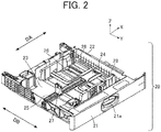
- FIG. 2 is a perspective view of a sheet feeding tray according to the one embodiment of this disclosure.
- the sheet feeding tray 20 that functions as a sheet loading device is formed in a substantially rectangular parallelepiped box shape.
- the sheet feeding tray 20 includes a device body 22 into which sheets are loaded.
- the device body 22 includes a bottom plate 24 for raising sheets S, a first guide rail 25, a second guide rail 26, an end fence 27, and a side fence 28, which are provided on a base portion 23 of the device body 22.
- the sheet feeding tray 20 includes an exterior cover 21 provided at one of four sides of the sheet feeding tray 20.
- the exterior cover 21 includes a handle 21a provided at a central portion of the exterior cover 21. A user can grip the handle 21a to insert or remove the sheet feeding tray 20 in ⁇ Y directions with respect to the image forming apparatus 1000.
- the sheets S are loaded inside the sheet feeding tray 20 that is pulled in the +Y direction. Then, the sheet feeding tray 20 is pushed in the -Y direction to be mounted in an apparatus body of the image forming apparatus 1000.
- the sheet feeding tray 20 includes the end fence 27 (a single unit) and a pair of the side fences 28.
- the end fence 27 and the pair of side fences 28 are provided such that upper space (space for loading the sheets S), in which the bottom plate 24 is provided, is surrounded by the end fence 27 and the pair of side fences 28 on three sides other than a forward side in a sheet conveying direction DA (+X direction).
- the first guide rail 25 that functions as a guide is provided on the base portion 23, extending in the sheet conveying direction DA ( ⁇ X directions).
- the end fence 27 can be manually moved in the sheet conveying direction DA, along the first guide rail 25, to be positioned according to the size of the sheets S in the sheet conveying direction DA. That is, the end fence 27 functions as a first restricting member that functions as a restricting body to restrict an end position of the sheets S in the sheet conveying direction DA.
- the second guide rail 26, as a guide is provided on the base portion 23, extending in a sheet width direction DB ( ⁇ Y directions).
- the pair of side fences 28 are installed at respective ends in the sheet width direction DB so as to hold the sheets S between the pair of side fences 28.
- the pair of side fences 28 can be manually moved in the sheet width direction DB, along the second guide rail 26, to be positioned according to the size of the sheets S in the sheet width direction DB. That is, the side fence 28 functions as a second restricting member that functions as another restricting body to restrict a position of the sheets S in the sheet width direction DB in a position different from the end fence 27.
- the pair of side fences 28 operate in conjunction with each other to increase or decrease an interval in the sheet width direction DB. That is, when one of the side fences 28 is manually moved in the +Y direction, the other side fence 28 moves in the -Y direction in conjunction with the movement of the one of the side fences 28. In addition, when one of the side fences 28 is manually moved in the -Y direction, the other side fence 28 moves in the +Y direction in conjunction with the movement of the one of the side fences 28.
- a rack and pinion mechanism can be used as a movement mechanism for causing the pair of side fences 28 to move in conjunction with each other, as described above.
- This mechanism includes a first rack gear, a second rack gear, and a pinion gear.
- the first rack gear is integrally formed, extending in the sheet width direction DB orthogonally to one of the side fences 28.
- the second rack gear is integrally formed, extending in the sheet width direction DB orthogonally to the other side fence 28.
- the pinion gear is disposed between the first rack gear and the second rack gear to be engaged with both rack gears.
- FIG. 2 is based on the assumption that the sheets S are fed in the X direction, and the sheet feeding tray 20 can be inserted or removed in the ⁇ Y directions. Meanwhile, this disclosure is not limited to these directions.
- FIG. 3A is a cross-sectional view of a lifting mechanism of the bottom plate.
- FIG. 3B is a perspective view of the lifting mechanism of the bottom plate.
- a lifting lever 24a is provided, as a mechanism for moving the bottom plate 24 up and down, between the bottom plate 24 and the base portion 23.
- the lifting lever 24a is driven by a motor 29 to rotate.
- the bottom plate 24 is rotationally movable around a back end in the sheet conveying direction DA
- the lifting lever 24a is rotationally movable around a lifting lever shaft 24b.
- the lifting lever 24a is driven by the motor 29 to rotate to lift the bottom plate 24 up and down.
- the sheet feeding tray 20 can smoothly feed the loaded sheets S regardless of the number of the loaded sheets S.
- a compression spring that is urged or limited with respect to urging force in conjunction with insertion or removal of the sheet feeding tray 20.
- FIG. 4A is a perspective view of the first guide rail and the end fence according to the one embodiment of this disclosure, viewed from obliquely above.
- FIG. 4B is a perspective view of the first guide rail and the end fence viewed from obliquely below.
- the first guide rail 25 includes walls formed in a manner to hold a lower portion of the end fence 27 disposed between the walls.
- One of the walls includes a rack 25a subjected to gear cutting.
- the first guide rail 25 includes a guide groove 25b for supporting and guiding a bottom portion of the end fence 27.
- the bottom portion of the end fence 27 is supported by a support pin 30, with the first guide rail 25 interposed between the bottom portion of the end fence 27 and the support pin 30.
- the end fence 27 includes a latch 31 to be engaged with the rack 25a of the first guide rail 25, and an operation member 27a for operating the latch 31.
- the latch 31 is urged by a spring, and constantly engaged with the rack 25a.
- the latch 31 is separated from the rack 25a in conjunction with operation of the operation member 27a. That is, operating the operation member 27a in a predetermined direction (direction of an arrow A in the drawing) enables the end fence 27 to be secured to or released from the first guide rail 25.
- the end fence 27 When the operation member 27a is operated to put the end fence 27 in a released state, the end fence 27 can freely move on the first guide rail 25. Meanwhile, when the operation member 27a is released, the latch 31 automatically engages with the rack 25a to secure the end fence 27 to the first guide rail 25. In this manner, the end fence 27 according to the present embodiment can be secured to the first guide rail 25 in an arbitrary position on the first guide rail 25.
- the end fence 27 has engagement holes 32 to be engaged with a securing member to be described below. Details of the characteristics of the securing member will be described below.
- the securing member is one of characteristic features of the present disclosure, and will be described below in more detail.
- FIG. 5A is a perspective view of the end fence and the securing member according to the one embodiment of this disclosure, viewed from obliquely above.
- FIG. 5B is a perspective view of the end fence and the securing member viewed from obliquely below.
- a securing member 33 is attached to the end fence 27.
- the securing member 33 functions as a securing body that is an error proofing (foolproof) jig used to prevent such a careless mistake.
- FIG. 6A is a plan view of the securing member according to the one embodiment of this disclosure.
- FIG. 6B is a perspective view of the securing member.
- FIG. 7A is a plan view of a back side of the securing member according to the one embodiment of this disclosure, in a secured state.
- FIG. 7B is a plan view of the back side of the securing member in the released state.
- the securing member 33 includes a securing plate 34, an operation member 35, and a latch 36.
- the securing plate 34 serves as a base.
- the operation member 35 is rotatably provided on the securing plate 34.
- the latch 36 engages with the rack 25a of the first guide rail 25.
- the securing member 33 includes, on the back side, two engagement pins 37 and an engagement tool 38.
- the engagement tool 38 that functions as an engaging body is rotated by the operation member 35 that functions as a switching body.
- each of the engagement pins 37 of the securing member 33 is an example of an engaging body
- the engagement tool 38 of the securing member 33 is an example of an engaging body.
- the two engagement pins 37 have a shape corresponding to the shape of the engagement holes 32 of the end fence 27.
- the engagement tool 38 of the securing member 33 is formed as a T-shaped protrusion, and rotated by the operation member 35 to engage with the guide groove 25b.
- the guide groove 25b is provided in the first guide rail 25, and continuously extends in a direction parallel to a direction in which the first guide rail 25 extends, that is, in the sheet conveying direction DA (see FIGS. 4A and 4B ).
- the engagement hole 32 (functioning as an engagement opening) of the end fence 27 is an example of an engagement target body to be engaged corresponding to a corresponding one of the engagement pins 37 (that functions as an engaging body) of the securing member 33.
- the guide groove 25b is an example of another engagement target body to be engaged corresponding to the engagement tool 38 (that functions as an engaging body) of the securing member 33.
- the securing member 33 can be attached to and detached from the end fence 27 and the first guide rail 25.
- An attachment procedure is as follows. First, while the engagement pins 37 of the securing member 33 are engaged with the engagement holes 32 of the end fence 27, the securing member 33 is attached to the first guide rail 25. At this time, the latch 36 of the securing member 33 engages with the rack 25a of the first guide rail 25 to fix the position of the securing member 33 with respect to the first guide rail 25.
- the operation member 35 is operated (rotated) to engage the engagement tool 38 of the securing member 33 with the guide groove 25b of the first guide rail 25.
- the securing member 33 is firmly secured in position (see FIG. 5B ).
- the term "firmly” means that the end fence 27 cannot be moved even by operating the operation member 27a. It is to be noted that it is possible to detach the securing member 33 by following the above-described procedure in reverse order.
- the bottom of the end fence is screwed to a screw hole provided in the sheet feeding tray in advance. Accordingly, the end fence can be secured only in a fixed position. Therefore, the screw-securing configuration of the comparative sheet feeding tray cannot handle a paper sheet in a size other than regular sizes or a paper sheet with a minute error in paper size (paper cutting error).
- the sheet feeding tray 20 includes the securing member 33 that is attachable and detachable.
- the securing member 33 can secure the end fence 27 in an arbitrary position in a direction in which the guide groove 25b extends, i.e., in the sheet conveying direction DA. Therefore, even in the case of a paper sheet in a size other than regular sizes or a paper sheet with a minute error in paper size, the end fence 27 can be firmly secured according to the size of the paper sheet.
- the engagement tool 38 of the securing member 33 may be formed in a cam shape such that the operation member 35 is operated (rotated) to cause the engagement tool 38 to be secured, by frictional force, to the walls (one of the walls includes the rack 25a) of the first guide rail 25.
- the guide groove 25b of the first guide rail 25 is not used to attach the securing member 33.
- the first guide rail 25 functions as an engagement target body to be engaged.
- the securing member 33 is attached to (engaged with) the guide groove 25b in the above-described embodiment, this disclosure is not limited thereto.
- a dedicated groove or rail that continuously extends in parallel with the first guide rail 25, and engages with the engagement tool 38 of the securing member 33.
- the dedicated groove or rail may be provided directly below the rack 25a of the first guide rail 25 or on a side opposite to the securing member 33 with respect to the rack 25a.
- the securing member 33 can secure the end fence 27 in an arbitrary position in a direction in which the dedicated groove or rail (member to be engaged) extends, i.e., in the sheet conveying direction DA.
- the device body 22, the first guide rail 25, and the second guide rail 26 need not be integrally formed. It is possible to provide the device body 22, the first guide rail 25, and the second guide rail 26 as separate parts, and attach the first guide rail 25 and the second guide rail 26 to the device body 22.
- the securing member 33 and the end fence 27 just need to include at least a set of an engagement pin and an engagement hole corresponding to each other. Accordingly, an engagement hole may be provided in the securing member 33, and an engagement pin may be provided on the end fence 27.
- FIG. 8A is a perspective view of the sheet feeding tray, to which the securing member has been attached, with the bottom plate raised.
- FIG. 8B is an enlarged view of an area in the vicinity of the securing member.
- the securing member 33 be provided such that an upper surface of the securing member 33 in a vertical direction (i.e., Z direction) does not protrude from the bottom plate 24, or the upper surface protrudes from the bottom plate 24 by 2 mm or less.
- the upper surface of the securing member 33 protrudes in the vertical direction from the bottom plate in a range of 0 mm to 2 mm.
- the sheets S be out of contact with the securing member 33 even when the sheets S are loaded onto the bottom plate 24.
- the end fence 27 has at least the engagement holes 32 that engage with the engagement pins 37 of the securing member 33.
- the engagement holes 32 have clearance (play of approximately 2 mm) such that the engagement pins 37 can move in a direction of the first guide rail 25.
- the engagement hole 32 of the end fence 27 is formed in a shape of a combination of a triangle and a quadrangle, viewed from above.
- a triangular portion can be used for visually recognizing a scale of sheet sizes (for example, A4 and B5) provided on the base portion 23.
- a quadrangular portion can be used as clearance (play) for allowing each of the engagement pin 37 of the securing member 33 to move.
- the above-described shape serves both functions, and is advantageous in this respect.
- the operation member 35 of the securing member 33 it is desirable for the operation member 35 of the securing member 33 to include a click mechanism 150 that generates a click feeling at the time of operation.
- a recess 40 is provided in (a back side of) the securing plate 34, and the operation member 35 includes a first protrusion 41a and a second protrusion 41b.
- the first protrusion 41a and the second protrusion 41b of the operation member 35 are out of phase by 90°.
- the second protrusion 41b is fitted in the recess 40 at a first position ( FIG. 7A ).
- the first protrusion 41a is fitted in the recess 40 at a second position ( FIG. 7B ).
- the operation member 35 In order to change the position from the first position to the second position, the operation member 35 is rotated by 90°. When the operation member 35 is rotated, either the first protrusion 41a or the second protrusion 41b runs onto a portion other than the recess 40 to generate resistance. The resistance is eliminated only when one of the protrusions is fitted in the recess 40 at the first position or the second position. Therefore, it is possible to generate an appropriate click feeling at the first position or the second position.
- a mark 45a indicating the secured state and a mark 45b indicating the released state are desirable to make a mark 45a indicating the secured state and a mark 45b indicating the released state, on an outer surface of the securing plate 34.
- the marks 45a and 45b made on the securing plate 34 facilitate determination as to whether the engagement tool 38 is in the secured state (the first position) or the released state (the second position).
- FIG. 9 is an enlarged perspective view of the operation member according to the one embodiment of this disclosure.
- the operation member 35 it is desirable for the operation member 35 to include a knurled portion 46 such that the end fence 27 can be secured or released by manual rotation of the operation member 35.
- a crossed groove 47 so as to enable the end fence 27 to be secured or released with a Phillips-head screwdriver, or to provide a coin groove 48 so as to enable the end fence 27 to be secured or released with a coin. This enables a user to operate (rotate) the operation member 35 by various means, resulting in enhancement in operability.
- a securing screw is removed in the case where an end fence is not secured.
- storage of the securing screw is left entirely to a user. Accordingly, there are cases where the user loses the securing screw by mistake.
- the securing member 33 according to this disclosure can also be detached from the sheet feeding tray 20. Thus, there is a possibility that a similar disadvantage may be caused. Therefore, described below is a configuration for preventing the securing member 33 according to this disclosure from being lost when not in use.
- FIG. 10A is a perspective view of the side fence according to the one embodiment of this disclosure.
- FIG. 10B is a perspective view illustrating the securing member in a held (housed) state.
- the side fence 28 includes a holding hole 50 that functions as an engaging body to hold the engagement tool 38 of the securing member 33, and engagement holes 51 that functions as an engaging body to engage with the engagement pins 37 of the securing member 33.
- a positional relationship between the holding hole 50 and the engagement holes 51 is the same as a positional relationship between the guide groove 25b of the first guide rail 25 and the engagement holes 32 of the end fence 27.
- a position of the securing member 33 in a height direction i.e., the vertical direction in FIGS. 10A and 10B
- a position of the securing member 33 in a lateral direction is determined by the engagement holes 51. Therefore, as illustrated in FIG. 10B , the securing member 33 can be held on the side fence 28 in an attachable and detachable manner.
- the holding hole 50 of the side fence 28 is an example of an engagement target body to be engaged corresponding to the engagement tool 38 (that functions as an engaging body) of the securing member 33.
- the engagement hole 51 of the side fence 28 is an example of another engagement target body to be engaged corresponding to a corresponding one of the engagement pins 37 (that functions as an engaging body) of the securing member 33.
- the securing member 33 can be held on a front side in a direction in which the sheet feeding tray 20 is pulled.
- the held securing member 33 does not interfere with the device body 22 or the bottom plate 24 of the sheet feeding tray 20 to affect the operability of the side fence 28.
- the position securing member is applicable to each regular size. Therefore, the sheet restricting member can be secured only in a prescribed position. In order to secure the sheet restricting member in an arbitrary position, it is necessary to prepare the position securing member for each size, resulting in an increase in the number of parts. Moreover, it is also necessary to secure additional space for storing such position securing members.
- the holding hole 50 and the engagement hole 51 of the side fence 28 have shapes corresponding to the shapes of the engagement tool 38 and each of the engagement pins 37 of the securing member 33, respectively.
- positions of the engagement holes 51 relative to the holding hole 50 are the same as positions of the engagement holes 32 of the end fence 27 relative to the guide groove 25b of the first guide rail 25. Therefore, it is not necessary to separately provide dedicated parts or shapes so as to hold the securing member 33 on the side fence 28.
- the securing member 33 can be easily attached to or detached from either the side fence 28 or the first guide rail 25 in each position where the securing member 33 is held.
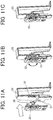
- FIGS. 11A to 11C are perspective views illustrating a procedure for attaching the securing member to the side fence.
- the engagement tool 38 of the securing member 33 is first inserted into the holding hole 50 of the side fence 28.
- each of the engagement pins 37 of the securing member 33 is inserted into the engagement hole 51 of the side fence 28.
- the operation member 35 is rotated by 90° to cause the engagement tool 38 of the securing member 33 to engage with the holding hole 50 of the side fence 28. Accordingly, as illustrated in FIG. 11C , the securing member 33 can be held on the side fence 28.
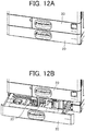
- FIGS. 12A and 12B are perspective views illustrating a position in which the securing member is held in the image forming apparatus 1000.
- the securing member 33 can be visually recognized from the direction in which the sheet feeding tray 20 is pulled. Accordingly, the securing member 33 can be easily recognized and attached or detached. Thus, it is possible to enhance both secure storage and ease of use.
- paper sheets are not limited to ones made of paper, but include ones referred to as a recorded medium, a recording medium, recording paper, and a recording paper sheet.
- image formation, recording, and printing are regarded as synonymous.
- the securing member 33 may be used to secure the side fence 28 to the device body 22.
- the image forming apparatus 1000 including the sheet loading device according to this disclosure is not limited to a copying machine or a printer, but may be a facsimile machine or a multifunction peripheral having a plurality of functions.
Landscapes
- Physics & Mathematics (AREA)
- General Physics & Mathematics (AREA)
- Engineering & Computer Science (AREA)
- Mechanical Engineering (AREA)
- Sheets, Magazines, And Separation Thereof (AREA)
- Pile Receivers (AREA)
Abstract
Description
- This disclosure relates to a sheet loading device and an image forming apparatus incorporating the sheet loading device.
- In an electrophotographic image forming apparatus, a sheet feeding tray (cassette) into which paper sheets (sheets) are loaded includes a restricting member (fence or guide) that restricts an end position of the paper sheets. The restricting members include an end fence and a side fence. The end fence restricts a back end in a sheet conveyance direction. The side fence restricts an end in a sheet width direction.
- Generally, an image forming apparatus has a function of recognizing at least one position of the end fence and the position of the side fence, and automatically setting a paper size. Therefore, in the case where the end fence is set in an incorrect position, loading paper sheets in an inappropriate position causes failure in sheet feeding, in which no paper sheet is fed from the sheet feeding tray. Furthermore, a size recognized as being different from the size of loaded paper sheets causes failure in conveyance, such as occurrence of a paper jam in a sheet conveyance passage.
- There is a known configuration in which the end fence and the side fence are screwed and secured to the sheet feeding tray for the purpose of preventing an incorrect setting of the end fence. In addition,
JP-2015-229536-A - However, with the screw-securing configuration, the bottom of the end fence is screwed to a screw hole provided in the sheet feeding tray in advance. Accordingly, the end fence can be secured only in a fixed position. Therefore, the screw-securing configuration has a disadvantage in that it is not possible to handle a paper sheet in a size other than regular sizes or a paper sheet with a minute error in paper size (paper cutting error).
- Furthermore, in the configuration disclosed in
JP-2015-229536-A - In view of the above, an object of this disclosure is to provide a sheet loading device capable of securing a restricting member in an arbitrary position according to the size of a paper sheet even in the case of a paper sheet in a size other than regular sizes or a paper sheet with a minute error in paper size.
- At least one aspect of this disclosure provides a sheet loading device including a device body, a guide, a restricting body, and a securing body. The device body loads a sheet. The guide is disposed extending in a sheet conveying direction in the device body. The restricting body moves along the guide of the device body and to restrict a position of an end portion of the sheet. The securing body attaches to the restricting body and the guide and detaches from the restricting body and the guide. The restricting body is being secured to the device body at an arbitrary position on the guide by engagement of the securing body with the device body.
- Further, at least one aspect of this disclosure provides an image forming apparatus including the above-described sheet loading device.
- Accordingly, a sheet loading apparatus according to the present embodiment of this disclosure includes a securing member that can be attached to and be detached from a first restricting member and a guide of a housing. The securing member can be engaged with (secured to) the guide in an arbitrary position on the guide. Therefore, the first restricting member can be secured to the housing in the arbitrary position on the guide.
- The aforementioned and other aspects, features, and advantages of this disclosure would be better understood by reference to the following detailed description when considered in connection with the accompanying drawings, wherein:
-
FIG. 1 is a schematic diagram illustrating an image forming apparatus according to one embodiment of this disclosure; -
FIG. 2 is a perspective view of a sheet feeding tray according to the one embodiment of this disclosure; -
FIG. 3A is a cross-sectional view of a lifting mechanism of a bottom plate; -
FIG. 3B is a perspective view of the lifting mechanism of the bottom plate; -
FIG. 4A is a perspective view of a first guide rail and an end fence according to the one embodiment of this disclosure, viewed from obliquely above; -
FIG. 4B is a perspective view of the first guide rail and the end fence viewed from obliquely below; -
FIG. 5A is a perspective view of the end fence and a securing member according to the one embodiment of this disclosure, viewed from obliquely above; -
FIG. 5B is a perspective view of the end fence and the securing member viewed from obliquely below; -
FIG. 6A is a plan view of the securing member according to the one embodiment of this disclosure; -
FIG. 6B is a perspective view of the securing member; -
FIG. 7A is a plan view of a back side of the securing member according to the one embodiment of this disclosure, in a secured state; -
FIG. 7B is a plan view of the back side of the securing member in a released state; -
FIG. 8A is a perspective view of the sheet feeding tray, to which the securing member has been attached, with the bottom plate raised; -
FIG. 8B is an enlarged view of an area in the vicinity of the securing member; -
FIG. 9 is an enlarged perspective view of an operation member according to the one embodiment of this disclosure; -
FIG. 10A is a perspective view of a side fence according to the one embodiment of this disclosure; -
FIG. 10B is a perspective view illustrating the securing member in a held (housed) state; -
FIGS. 11A to 11C are perspective views illustrating a procedure for attaching the securing member to the side fence; and -
FIGS. 12A and 12B are perspective views illustrating a position in which the securing member is held in the image forming apparatus. - The accompanying drawings are intended to depict embodiments of this disclosure and should not be interpreted to limit the scope thereof. The accompanying drawings are not to be considered as drawn to scale unless explicitly noted.
- It will be understood that if an element or layer is referred to as being "on", "against", "connected to" or "coupled to" another element or layer, then it can be directly on, against, connected or coupled to the other element or layer, or intervening elements or layers may be present. In contrast, if an element is referred to as being "directly on", "directly connected to" or "directly coupled to" another element or layer, then there are no intervening elements or layers present. Like numbers referred to like elements throughout. As used herein, the term "and/or" includes any and all combinations of one or more of the associated listed items.
- Spatially relative terms, such as "beneath", "below", "lower", "above", "upper" and the like may be used herein for ease of description to describe one element or feature's relationship to another element(s) or feature(s) as illustrated in the figures. It will be understood that the spatially relative terms are intended to encompass different orientations of the device in use or operation in addition to the orientation depicted in the figures. For example, if the device in the figures is turned over, elements describes as "below" or "beneath" other elements or features would then be oriented "above" the other elements or features. Thus, term such as "below" can encompass both an orientation of above and below. The device may be otherwise oriented (rotated 90 degrees or at other orientations) and the spatially relative descriptors herein interpreted accordingly.
- Although the terms first, second, etc. may be used herein to describe various elements, components, regions, layers and/or sections, it should be understood that these elements, components, regions, layer and/or sections should not be limited by these terms. These terms are used to distinguish one element, component, region, layer or section from another region, layer or section. Thus, a first element, component, region, layer or section discussed below could be termed a second element, component, region, layer or section without departing from the teachings of the present disclosure.
- The terminology used herein is for describing particular embodiments and examples and is not intended to be limiting of exemplary embodiments of this disclosure. As used herein, the singular forms "a", "an" and "the" are intended to include the plural forms as well, unless the context clearly indicates otherwise. It will be further understood that the terms "includes" and/or "including", when used in this specification, specify the presence of stated features, integers, steps, operations, elements, and/or components, but do not preclude the presence or addition of one or more other features, integers, steps, operations, elements, components, and/or groups thereof.
- Descriptions are given, with reference to the accompanying drawings, of examples, exemplary embodiments, modification of exemplary embodiments, etc., of an image forming apparatus according to exemplary embodiments of this disclosure. Elements having the same functions and shapes are denoted by the same reference numerals throughout the specification and redundant descriptions are omitted. Elements that do not demand descriptions may be omitted from the drawings as a matter of convenience. Reference numerals of elements extracted from the patent publications are in parentheses so as to be distinguished from those of exemplary embodiments of this disclosure.
- This disclosure is applicable to any image forming apparatus, and is implemented in the most effective manner in an electrophotographic image forming apparatus.
- In describing preferred embodiments illustrated in the drawings, specific terminology is employed for the sake of clarity. However, the disclosure of this disclosure is not intended to be limited to the specific terminology so selected and it is to be understood that each specific element includes any and all technical equivalents that have the same function, operate in a similar manner, and achieve a similar result.
- Referring now to the drawings, wherein like reference numerals designate identical or corresponding parts throughout the several views, preferred embodiments of this disclosure are described.
- Descriptions are given of an example applicable to a sheet loading device, and an image forming apparatus incorporating the sheet loading device.
- It is to be noted that elements (for example, mechanical parts and components) having the same functions and shapes are denoted by the same reference numerals throughout the specification and redundant descriptions are omitted.
- Now, a description is given of the sheet conveying device according to this disclosure with reference to the following figures.
-
FIG. 1 is a schematic diagram illustrating animage forming apparatus 1000 according to one embodiment of this disclosure. - The
image forming apparatus 1000 may be a copier, a facsimile machine, a printer, a multifunction peripheral or a multifunction printer (MFP) having at least one of copying, printing, scanning, facsimile, and plotter functions, or the like. According to the present example, theimage forming apparatus 1000 is an inkjet image forming apparatus that forms toner images on recording media by discharging ink to the recording media. - It is to be noted in the following examples that: the term "image forming apparatus" indicates an apparatus in which an image is formed on a recording medium such as paper, OHP (overhead projector) transparencies, OHP film sheet, thread, fiber, fabric, leather, metal, plastic, glass, wood, and/or ceramic by attracting developer or ink thereto; the term "image formation" indicates an action for providing (i.e., printing) not only an image having meanings such as texts and figures on a recording medium but also an image having no meaning such as patterns on a recording medium; and the term "sheet" is not limited to indicate a paper material but also includes the above-described plastic material (e.g., an OHP sheet), a fabric sheet and so forth, and is used to which the developer or ink is attracted. In addition, the "sheet" is not limited to a flexible sheet but is applicable to a rigid plate-shaped sheet and a relatively thick sheet.
- Further, size (dimension), material, shape, and relative positions used to describe each of the components and units are examples, and the scope of this disclosure is not limited thereto unless otherwise specified.
- Further, it is to be noted in the following examples that: the term "sheet conveying direction" indicates a direction in which a recording medium travels from an upstream side of a sheet conveying path to a downstream side thereof; the term "width direction" indicates a direction basically perpendicular to the sheet conveying direction.
- As illustrated in
FIG. 1 , theimage forming apparatus 1000 includes asheet conveyer 100, animage forming device 200, and animage reader 300. Theimage forming device 200 is provided substantially above thesheet conveyer 100. Theimage reader 300 is further provided above theimage forming device 200. Thesheet conveyer 100 includes, as a sheet feeder, asheet feeding tray 20 into which paper sheets (sheets) S are loaded, apickup roller 2a for sending the paper sheets S on thesheet feeding tray 20, and a pair of rollers (afeed roller 2b and areverse roller 2c) for separating the paper sheets S. Furthermore, thesheet conveyer 100 includesconveyance rollers registration rollers sheet conveyer 100 conveys the paper sheets S sent from thesheet feeding tray 20 toward theimage forming device 200. - It is to be noted that
FIG. 1 is a schematic diagram. In addition to the illustrated ones, thesheet conveyer 100 also includes a plurality of pairs of rollers for conveying the paper sheets S. The plurality of pairs of rollers is provided at intervals appropriate for conveying the paper sheets S. - The
image forming device 200 includes a photoconductor (transfer roller) 14, acharger 5 disposed on the periphery of the photoconductor (transfer roller) 14, a developingmeans 6, atransferrer 7, acleaner 8, aconveyance belt 9 for conveying a paper sheet S to which an image has been transferred. Furthermore, theimage forming device 200 also includes a fixingdevice 10, and awriter 11. The fixingdevice 10 fixes the paper sheet S on which the image has been formed. Thewriter 11 partially exposes the photoconductor (transfer roller) 14 uniformly charged, to form a latent image. - Next, a process of forming an image on the paper sheet S will be described. When a sheet feeding signal is turned on, the
pickup roller 2a descends and rotates to send the paper sheets S on thesheet feeding tray 20. The sent paper sheets S are separated one by one at a nip between thefeed roller 2b and thereverse roller 2c to reach theconveyance rollers registration rollers - Next, the
image forming device 200 forms an image on the paper sheet S supplied from thesheet conveyer 100 and causes the image on the paper sheet S to be fixed by the fixingdevice 10. The paper sheet S on which the image has been fixed is ejected into asheet ejection tray 13 viasheet ejection rollers 12. -
FIG. 2 is a perspective view of a sheet feeding tray according to the one embodiment of this disclosure. As illustrated inFIG. 2 , thesheet feeding tray 20 that functions as a sheet loading device is formed in a substantially rectangular parallelepiped box shape. Thesheet feeding tray 20 includes adevice body 22 into which sheets are loaded. Thedevice body 22 includes abottom plate 24 for raising sheets S, afirst guide rail 25, asecond guide rail 26, anend fence 27, and aside fence 28, which are provided on abase portion 23 of thedevice body 22. In addition, thesheet feeding tray 20 includes anexterior cover 21 provided at one of four sides of thesheet feeding tray 20. Theexterior cover 21 includes ahandle 21a provided at a central portion of theexterior cover 21. A user can grip thehandle 21a to insert or remove thesheet feeding tray 20 in ±Y directions with respect to theimage forming apparatus 1000. - Specifically, the sheets S are loaded inside the
sheet feeding tray 20 that is pulled in the +Y direction. Then, thesheet feeding tray 20 is pushed in the -Y direction to be mounted in an apparatus body of theimage forming apparatus 1000. - The
sheet feeding tray 20 includes the end fence 27 (a single unit) and a pair of theside fences 28. Theend fence 27 and the pair ofside fences 28 are provided such that upper space (space for loading the sheets S), in which thebottom plate 24 is provided, is surrounded by theend fence 27 and the pair ofside fences 28 on three sides other than a forward side in a sheet conveying direction DA (+X direction). - The
first guide rail 25 that functions as a guide is provided on thebase portion 23, extending in the sheet conveying direction DA (±X directions). Theend fence 27 can be manually moved in the sheet conveying direction DA, along thefirst guide rail 25, to be positioned according to the size of the sheets S in the sheet conveying direction DA. That is, theend fence 27 functions as a first restricting member that functions as a restricting body to restrict an end position of the sheets S in the sheet conveying direction DA. - In addition, the
second guide rail 26, as a guide, is provided on thebase portion 23, extending in a sheet width direction DB (±Y directions). The pair ofside fences 28 are installed at respective ends in the sheet width direction DB so as to hold the sheets S between the pair ofside fences 28. The pair ofside fences 28 can be manually moved in the sheet width direction DB, along thesecond guide rail 26, to be positioned according to the size of the sheets S in the sheet width direction DB. That is, theside fence 28 functions as a second restricting member that functions as another restricting body to restrict a position of the sheets S in the sheet width direction DB in a position different from theend fence 27. - In the present embodiment, the pair of
side fences 28 operate in conjunction with each other to increase or decrease an interval in the sheet width direction DB. That is, when one of theside fences 28 is manually moved in the +Y direction, theother side fence 28 moves in the -Y direction in conjunction with the movement of the one of theside fences 28. In addition, when one of theside fences 28 is manually moved in the -Y direction, theother side fence 28 moves in the +Y direction in conjunction with the movement of the one of theside fences 28. - A rack and pinion mechanism can be used as a movement mechanism for causing the pair of
side fences 28 to move in conjunction with each other, as described above. This mechanism includes a first rack gear, a second rack gear, and a pinion gear. The first rack gear is integrally formed, extending in the sheet width direction DB orthogonally to one of theside fences 28. The second rack gear is integrally formed, extending in the sheet width direction DB orthogonally to theother side fence 28. The pinion gear is disposed between the first rack gear and the second rack gear to be engaged with both rack gears. - It is to be noted that
FIG. 2 is based on the assumption that the sheets S are fed in the X direction, and thesheet feeding tray 20 can be inserted or removed in the ±Y directions. Meanwhile, this disclosure is not limited to these directions. -
FIG. 3A is a cross-sectional view of a lifting mechanism of the bottom plate.FIG. 3B is a perspective view of the lifting mechanism of the bottom plate. As illustrated inFIGS. 3A and 3B , a liftinglever 24a is provided, as a mechanism for moving thebottom plate 24 up and down, between thebottom plate 24 and thebase portion 23. The liftinglever 24a is driven by amotor 29 to rotate. Specifically, thebottom plate 24 is rotationally movable around a back end in the sheet conveying direction DA, and the liftinglever 24a is rotationally movable around a liftinglever shaft 24b. The liftinglever 24a is driven by themotor 29 to rotate to lift thebottom plate 24 up and down. As a result, a forward end of thebottom plate 24 in the sheet conveying direction DA can be moved up and down. Furthermore, themotor 29 is appropriately controlled by a controller of theimage forming apparatus 1000. Therefore, thesheet feeding tray 20 can smoothly feed the loaded sheets S regardless of the number of the loaded sheets S. - Alternatively, instead of the above, there may be provided a compression spring that is urged or limited with respect to urging force in conjunction with insertion or removal of the
sheet feeding tray 20. -
FIG. 4A is a perspective view of the first guide rail and the end fence according to the one embodiment of this disclosure, viewed from obliquely above.FIG. 4B is a perspective view of the first guide rail and the end fence viewed from obliquely below. As illustrated inFIG. 4A , thefirst guide rail 25 includes walls formed in a manner to hold a lower portion of theend fence 27 disposed between the walls. One of the walls includes arack 25a subjected to gear cutting. In addition, thefirst guide rail 25 includes aguide groove 25b for supporting and guiding a bottom portion of theend fence 27. As illustrated inFIG. 4B , the bottom portion of theend fence 27 is supported by asupport pin 30, with thefirst guide rail 25 interposed between the bottom portion of theend fence 27 and thesupport pin 30. - Furthermore, as illustrated in
FIG. 4A , theend fence 27 includes alatch 31 to be engaged with therack 25a of thefirst guide rail 25, and anoperation member 27a for operating thelatch 31. Thelatch 31 is urged by a spring, and constantly engaged with therack 25a. Thelatch 31 is separated from therack 25a in conjunction with operation of theoperation member 27a. That is, operating theoperation member 27a in a predetermined direction (direction of an arrow A in the drawing) enables theend fence 27 to be secured to or released from thefirst guide rail 25. - When the
operation member 27a is operated to put theend fence 27 in a released state, theend fence 27 can freely move on thefirst guide rail 25. Meanwhile, when theoperation member 27a is released, thelatch 31 automatically engages with therack 25a to secure theend fence 27 to thefirst guide rail 25. In this manner, theend fence 27 according to the present embodiment can be secured to thefirst guide rail 25 in an arbitrary position on thefirst guide rail 25. - Furthermore, the
end fence 27 has engagement holes 32 to be engaged with a securing member to be described below. Details of the characteristics of the securing member will be described below. The securing member is one of characteristic features of the present disclosure, and will be described below in more detail. -
FIG. 5A is a perspective view of the end fence and the securing member according to the one embodiment of this disclosure, viewed from obliquely above.FIG. 5B is a perspective view of the end fence and the securing member viewed from obliquely below. As illustrated inFIGS. 5A and 5B , in the present embodiment, a securingmember 33 is attached to theend fence 27. As described above, while theend fence 27 can be secured to thefirst guide rail 25 in an arbitrary position on thefirst guide rail 25, a simple operation allows theend fence 27 to be movable. Therefore, there has been a possibility that a user erroneously moves theend fence 27 to cause an operational error such as loading paper sheets in different sizes. The securingmember 33 functions as a securing body that is an error proofing (foolproof) jig used to prevent such a careless mistake. -
FIG. 6A is a plan view of the securing member according to the one embodiment of this disclosure.FIG. 6B is a perspective view of the securing member.FIG. 7A is a plan view of a back side of the securing member according to the one embodiment of this disclosure, in a secured state.FIG. 7B is a plan view of the back side of the securing member in the released state. - As illustrated in
FIGS. 6A and 6B , the securingmember 33 includes a securingplate 34, anoperation member 35, and alatch 36. The securingplate 34 serves as a base. Theoperation member 35 is rotatably provided on the securingplate 34. Thelatch 36 engages with therack 25a of thefirst guide rail 25. In addition, as illustrated inFIGS. 7A and 7B , the securingmember 33 includes, on the back side, twoengagement pins 37 and anengagement tool 38. Theengagement tool 38 that functions as an engaging body is rotated by theoperation member 35 that functions as a switching body. It is to be noted that each of the engagement pins 37 of the securingmember 33 is an example of an engaging body, and theengagement tool 38 of the securingmember 33 is an example of an engaging body. - The two
engagement pins 37 have a shape corresponding to the shape of the engagement holes 32 of theend fence 27. Theengagement tool 38 of the securingmember 33 is formed as a T-shaped protrusion, and rotated by theoperation member 35 to engage with theguide groove 25b. Theguide groove 25b is provided in thefirst guide rail 25, and continuously extends in a direction parallel to a direction in which thefirst guide rail 25 extends, that is, in the sheet conveying direction DA (seeFIGS. 4A and 4B ). - The engagement hole 32 (functioning as an engagement opening) of the
end fence 27 is an example of an engagement target body to be engaged corresponding to a corresponding one of the engagement pins 37 (that functions as an engaging body) of the securingmember 33. Theguide groove 25b is an example of another engagement target body to be engaged corresponding to the engagement tool 38 (that functions as an engaging body) of the securingmember 33. - The securing
member 33 can be attached to and detached from theend fence 27 and thefirst guide rail 25. An attachment procedure is as follows. First, while the engagement pins 37 of the securingmember 33 are engaged with the engagement holes 32 of theend fence 27, the securingmember 33 is attached to thefirst guide rail 25. At this time, thelatch 36 of the securingmember 33 engages with therack 25a of thefirst guide rail 25 to fix the position of the securingmember 33 with respect to thefirst guide rail 25. - Then, the
operation member 35 is operated (rotated) to engage theengagement tool 38 of the securingmember 33 with theguide groove 25b of thefirst guide rail 25. Thus, the securingmember 33 is firmly secured in position (seeFIG. 5B ). Here, the term "firmly" means that theend fence 27 cannot be moved even by operating theoperation member 27a. It is to be noted that it is possible to detach the securingmember 33 by following the above-described procedure in reverse order. - In a screw-securing configuration of a comparative sheet feeding tray that functions as a sheet loading device, the bottom of the end fence is screwed to a screw hole provided in the sheet feeding tray in advance. Accordingly, the end fence can be secured only in a fixed position. Therefore, the screw-securing configuration of the comparative sheet feeding tray cannot handle a paper sheet in a size other than regular sizes or a paper sheet with a minute error in paper size (paper cutting error).
- By contrast, as described above, the
sheet feeding tray 20 according to the present embodiment includes the securingmember 33 that is attachable and detachable. The securingmember 33 can secure theend fence 27 in an arbitrary position in a direction in which theguide groove 25b extends, i.e., in the sheet conveying direction DA. Therefore, even in the case of a paper sheet in a size other than regular sizes or a paper sheet with a minute error in paper size, theend fence 27 can be firmly secured according to the size of the paper sheet. - The above-described embodiment is merely an example, and various modifications can be made. For example, the
engagement tool 38 of the securingmember 33 may be formed in a cam shape such that theoperation member 35 is operated (rotated) to cause theengagement tool 38 to be secured, by frictional force, to the walls (one of the walls includes therack 25a) of thefirst guide rail 25. In such a case, theguide groove 25b of thefirst guide rail 25 is not used to attach the securingmember 33. It is to bee noted that thefirst guide rail 25 functions as an engagement target body to be engaged. - Furthermore, while the securing
member 33 is attached to (engaged with) theguide groove 25b in the above-described embodiment, this disclosure is not limited thereto. Separately from thefirst guide rail 25, there may be provided, for example, a dedicated groove or rail that continuously extends in parallel with thefirst guide rail 25, and engages with theengagement tool 38 of the securingmember 33. In thedevice body 22, the dedicated groove or rail may be provided directly below therack 25a of thefirst guide rail 25 or on a side opposite to the securingmember 33 with respect to therack 25a. - Thus, the securing
member 33 can secure theend fence 27 in an arbitrary position in a direction in which the dedicated groove or rail (member to be engaged) extends, i.e., in the sheet conveying direction DA. - Furthermore, the
device body 22, thefirst guide rail 25, and thesecond guide rail 26 need not be integrally formed. It is possible to provide thedevice body 22, thefirst guide rail 25, and thesecond guide rail 26 as separate parts, and attach thefirst guide rail 25 and thesecond guide rail 26 to thedevice body 22. - The securing
member 33 and theend fence 27 just need to include at least a set of an engagement pin and an engagement hole corresponding to each other. Accordingly, an engagement hole may be provided in the securingmember 33, and an engagement pin may be provided on theend fence 27. - Next, advantageous configurations of this disclosure will be described.
-
FIG. 8A is a perspective view of the sheet feeding tray, to which the securing member has been attached, with the bottom plate raised.FIG. 8B is an enlarged view of an area in the vicinity of the securing member. As illustrated inFIGS. 8A and 8B , it is desirable that the securingmember 33 be provided such that an upper surface of the securingmember 33 in a vertical direction (i.e., Z direction) does not protrude from thebottom plate 24, or the upper surface protrudes from thebottom plate 24 by 2 mm or less. In other words, the upper surface of the securingmember 33 protrudes in the vertical direction from the bottom plate in a range of 0 mm to 2 mm. Furthermore, it is preferable that the sheets S be out of contact with the securingmember 33 even when the sheets S are loaded onto thebottom plate 24. Thus, it is possible to attach the securingmember 33 without hindering the loading of the sheets S or damaging the sheets S. - As illustrated in
FIGS. 4A, 4B ,7A, and 7B above, theend fence 27 has at least the engagement holes 32 that engage with the engagement pins 37 of the securingmember 33. Here, it is desirable that the engagement holes 32 have clearance (play of approximately 2 mm) such that the engagement pins 37 can move in a direction of thefirst guide rail 25. Thus, even in the case where the securingmember 33 is attached, sheets can be easily loaded. Furthermore, even in the case where unevenness in paper size in the sheet conveyance direction is caused by, for example, a paper cutting error, it is possible to make fine adjustments to theend fence 27 to absorb unevenness. - In the present embodiment, the
engagement hole 32 of theend fence 27 is formed in a shape of a combination of a triangle and a quadrangle, viewed from above. A triangular portion can be used for visually recognizing a scale of sheet sizes (for example, A4 and B5) provided on thebase portion 23. A quadrangular portion can be used as clearance (play) for allowing each of theengagement pin 37 of the securingmember 33 to move. Thus, the above-described shape serves both functions, and is advantageous in this respect. - In order to address this convenience and enhance a sense of security for a user, it is desirable for the
operation member 35 of the securingmember 33 to include aclick mechanism 150 that generates a click feeling at the time of operation. In other words, it is desirable for theoperation member 35 to generate a click feeling that can be recognized by a user when the state of theengagement tool 38 is changed from the released state to the secured state, and when the state of theengagement tool 38 is changed from the secured state to the released state. - One embodiment of the
click mechanism 150 will be described below. As illustrated inFIGS. 7A and 7B above, arecess 40 is provided in (a back side of) the securingplate 34, and theoperation member 35 includes afirst protrusion 41a and asecond protrusion 41b. Thefirst protrusion 41a and thesecond protrusion 41b of theoperation member 35 are out of phase by 90°. In the secured state, thesecond protrusion 41b is fitted in therecess 40 at a first position (FIG. 7A ). In the released state, thefirst protrusion 41a is fitted in therecess 40 at a second position (FIG. 7B ). - In order to change the position from the first position to the second position, the
operation member 35 is rotated by 90°. When theoperation member 35 is rotated, either thefirst protrusion 41a or thesecond protrusion 41b runs onto a portion other than therecess 40 to generate resistance. The resistance is eliminated only when one of the protrusions is fitted in therecess 40 at the first position or the second position. Therefore, it is possible to generate an appropriate click feeling at the first position or the second position. - As illustrated in
FIGS. 6A and 6B above, it is desirable to make amark 45a indicating the secured state and amark 45b indicating the released state, on an outer surface of the securingplate 34. Themarks plate 34 facilitate determination as to whether theengagement tool 38 is in the secured state (the first position) or the released state (the second position). -
FIG. 9 is an enlarged perspective view of the operation member according to the one embodiment of this disclosure. As illustrated inFIG. 9 , it is desirable for theoperation member 35 to include aknurled portion 46 such that theend fence 27 can be secured or released by manual rotation of theoperation member 35. Similarly, it is desirable to provide a crossedgroove 47 so as to enable theend fence 27 to be secured or released with a Phillips-head screwdriver, or to provide acoin groove 48 so as to enable theend fence 27 to be secured or released with a coin. This enables a user to operate (rotate) theoperation member 35 by various means, resulting in enhancement in operability. - Next, a method for storing (housing) the securing
member 33 according to this disclosure will be described below. - In the conventional securing method using a screw, a securing screw is removed in the case where an end fence is not secured. In many cases, storage of the securing screw is left entirely to a user. Accordingly, there are cases where the user loses the securing screw by mistake. The securing
member 33 according to this disclosure can also be detached from thesheet feeding tray 20. Thus, there is a possibility that a similar disadvantage may be caused. Therefore, described below is a configuration for preventing the securingmember 33 according to this disclosure from being lost when not in use. -
FIG. 10A is a perspective view of the side fence according to the one embodiment of this disclosure.FIG. 10B is a perspective view illustrating the securing member in a held (housed) state. As illustrated inFIG. 10A , theside fence 28 includes a holdinghole 50 that functions as an engaging body to hold theengagement tool 38 of the securingmember 33, and engagement holes 51 that functions as an engaging body to engage with the engagement pins 37 of the securingmember 33. Here, a positional relationship between the holdinghole 50 and the engagement holes 51 is the same as a positional relationship between theguide groove 25b of thefirst guide rail 25 and the engagement holes 32 of theend fence 27. When the securingmember 33 is attached to theside fence 28, a position of the securingmember 33 in a height direction (i.e., the vertical direction inFIGS. 10A and 10B ) is determined by the holdinghole 50, and a position of the securingmember 33 in a lateral direction (horizontal direction inFIGS. 10A and 10B ) is determined by the engagement holes 51. Therefore, as illustrated inFIG. 10B , the securingmember 33 can be held on theside fence 28 in an attachable and detachable manner. - The holding
hole 50 of theside fence 28 is an example of an engagement target body to be engaged corresponding to the engagement tool 38 (that functions as an engaging body) of the securingmember 33. Theengagement hole 51 of theside fence 28 is an example of another engagement target body to be engaged corresponding to a corresponding one of the engagement pins 37 (that functions as an engaging body) of the securingmember 33. - In this manner, the securing
member 33 can be held on a front side in a direction in which thesheet feeding tray 20 is pulled. The held securingmember 33 does not interfere with thedevice body 22 or thebottom plate 24 of thesheet feeding tray 20 to affect the operability of theside fence 28. - In the configuration of a comparative sheet loading device, the position securing member is applicable to each regular size. Therefore, the sheet restricting member can be secured only in a prescribed position. In order to secure the sheet restricting member in an arbitrary position, it is necessary to prepare the position securing member for each size, resulting in an increase in the number of parts. Moreover, it is also necessary to secure additional space for storing such position securing members.
- By contrast, the holding
hole 50 and theengagement hole 51 of theside fence 28 have shapes corresponding to the shapes of theengagement tool 38 and each of the engagement pins 37 of the securingmember 33, respectively. In addition, positions of the engagement holes 51 relative to the holdinghole 50 are the same as positions of the engagement holes 32 of theend fence 27 relative to theguide groove 25b of thefirst guide rail 25. Therefore, it is not necessary to separately provide dedicated parts or shapes so as to hold the securingmember 33 on theside fence 28. Furthermore, the securingmember 33 can be easily attached to or detached from either theside fence 28 or thefirst guide rail 25 in each position where the securingmember 33 is held. -
FIGS. 11A to 11C are perspective views illustrating a procedure for attaching the securing member to the side fence. As illustrated inFIG. 11A , in order to attach the securingmember 33 to theside fence 28, theengagement tool 38 of the securingmember 33 is first inserted into the holdinghole 50 of theside fence 28. In addition, each of the engagement pins 37 of the securingmember 33 is inserted into theengagement hole 51 of theside fence 28. Next, as illustrated inFIG. 11B , theoperation member 35 is rotated by 90° to cause theengagement tool 38 of the securingmember 33 to engage with the holdinghole 50 of theside fence 28. Accordingly, as illustrated inFIG. 11C , the securingmember 33 can be held on theside fence 28. It is also possible to detach the securingmember 33 from the side fence 28 (sheet feeding tray 20) by following the above-described procedure in reverse order. Since the securingmember 33 can be held on theside fence 28, it is easy to visually recognize the securingmember 33 in thesheet feeding tray 20. -
FIGS. 12A and 12B are perspective views illustrating a position in which the securing member is held in theimage forming apparatus 1000. As illustrated inFIGS. 12A and 12B , when thesheet feeding tray 20 housed in theimage forming apparatus 1000 is pulled, the securingmember 33 can be visually recognized from the direction in which thesheet feeding tray 20 is pulled. Accordingly, the securingmember 33 can be easily recognized and attached or detached. Thus, it is possible to enhance both secure storage and ease of use. - In the present embodiment, "paper sheets" are not limited to ones made of paper, but include ones referred to as a recorded medium, a recording medium, recording paper, and a recording paper sheet. In addition, image formation, recording, and printing are regarded as synonymous.
- This disclosure has been described above in detail based on the embodiment. The embodiment is merely an example, and various modifications can be made without departing from the gist of this disclosure. For example, the embodiment, variations, and advantageous configurations may be combined. The securing
member 33 may be used to secure theside fence 28 to thedevice body 22. Furthermore, theimage forming apparatus 1000 including the sheet loading device according to this disclosure is not limited to a copying machine or a printer, but may be a facsimile machine or a multifunction peripheral having a plurality of functions.
Claims (15)
- A sheet loading device (20) comprising:a device body (22) to load a sheet (S);a guide (25) disposed extending in a sheet conveying direction in the device body (22);a restricting body (27) to move along the guide (25) of the device body (22) and to restrict a position of an end portion of the sheet (S); anda securing body (33) to attach to the restricting body (27) and the guide (25) and detach from the restricting body (27) and the guide (25),the restricting body (27) being secured to the device body (22) at an arbitrary position on the guide (25) by engagement of the securing body (33) with the device body (22).
- The sheet loading device (20) according to claim 1,
wherein the securing body (33) has an engaging body (38) to engage with the guide (25) at an arbitrary position on the guide (25) in the sheet conveying direction, and
wherein the restricting body (27) is secured to the device body (22) by engagement of the engaging body (38) of the securing body (33) with the guide (25) of the device body (22). - The sheet loading device (20) according to claim 1,
wherein the device body (22) further includes an engagement target body (25b) disposed separately from the guide (25) in the device body and extending in parallel with the guide (25) in the sheet conveying direction,
wherein the securing body (33) has an engaging body (38) to engage with the engagement target body (25b) at an arbitrary position on the engagement target body (25b) in the sheet conveying direction, and
wherein the restricting body (27) is secured to the device body (22) according to engagement of the engaging body (38) of the securing body (33) with the engagement target body (25b) of the device body (22). - The sheet loading device (20) according to claim 1 or claim 2,
wherein the securing body (33) and the restricting body (27) include at least a set of an engagement pin (37) and an engagement opening (32) corresponding to each other, and
wherein the engagement opening (32) has clearance via which the engagement pin (37) moves toward the guide (25). - The sheet loading device (20) according to any one of claims 1 to 3, wherein the securing body (33) includes a switching body (35) to operate the engaging body (38).
- The sheet loading device (20) according to claim 4,
wherein the switching body (35) includes a click mechanism (150) to generate a click feeling when a state of the engaging body (38) is changed from a released state to a secured state and when the state of the engaging body (38) is changed from the secured state to the released state. - The sheet loading device (20) according to claim 4 or claim 5,
wherein the securing body (33) includes a mark (45a, 45b) to determine whether the engaging body (38) is in one of a secured state and a released state. - The sheet loading device (20) according to any one of claims 4 to 6,
wherein the switching body (35) includes at least one of a knurled portion (46), a crossed groove (47), and a coin groove (48). - The sheet loading device (20) according to any one of claims 1 to 8, further comprising:a bottom plate (24) to move in a vertical direction and move the sheet in the vertical direction,wherein an upper surface of the securing body (33) in the vertical direction protrudes from the bottom plate (24) in a range of 0 mm to 2 mm.
- The sheet loading device (20) according to any one of claims 1 to 9, wherein the securing body (33) is detachably attached in the sheet loading device (20).
- The sheet loading device (20) according to claim 10,
wherein the securing body (33) is detachably attached to a side in a direction in which the sheet loading device is pulled. - The sheet loading device (20) according to claim 10, further comprising:another restricting body (28) movable in a direction perpendicular to the restricting body (27) and in which the sheet loading device is pulled,wherein the securing body (33) is detachably attachable to said another restricting body (28).
- The sheet loading device (20) according to any one of claims 10 to 12, wherein the securing body (33) is held at a position where the securing body (33) is visually recognized from a direction in which the sheet loading device (20) is pulled.
- The sheet loading device (20) according to claim 1, further comprising:a first engaging body (38) and a second engaging body (37), both provided to the securing body (33) being detachable from the sheet loading device (20),a first engagement target body (50) to be engaged with the first engaging body (38) of the securing body (33); anda second engagement target body (51) to be engaged with the second engaging body (37) of the securing body (33),wherein the securing body (33) is held by the first engagement target body (50) and the second engagement target body (51),wherein the device body (22) includes a third engagement target body (25b) to be engaged with the first engaging body (38) of the securing body (33),wherein the restricting body (27) includes a fourth engagement target body (32) to be engaged with the second engaging body (37) of the securing body (33), andwherein the first engaging body (38) of the securing body (33) engages with the third engagement target body (25b) and the second engaging body (37) of the securing body (33) engaging with the fourth engagement target body (32).
- An image forming apparatus (1000) comprising:
the sheet loading device (20) according to any one of claims 1 to 14.
Applications Claiming Priority (1)
| Application Number | Priority Date | Filing Date | Title |
|---|---|---|---|
| JP2018049708A JP7077692B2 (en) | 2018-03-16 | 2018-03-16 | Sheet loading device and image forming device |
Publications (2)
| Publication Number | Publication Date |
|---|---|
| EP3549777A1 true EP3549777A1 (en) | 2019-10-09 |
| EP3549777B1 EP3549777B1 (en) | 2022-06-08 |
Family
ID=65686734
Family Applications (1)
| Application Number | Title | Priority Date | Filing Date |
|---|---|---|---|
| EP19160598.9A Active EP3549777B1 (en) | 2018-03-16 | 2019-03-04 | Sheet loading device and image forming apparatus incorporating the sheet loading device |
Country Status (4)
| Country | Link |
|---|---|
| US (1) | US11066260B2 (en) |
| EP (1) | EP3549777B1 (en) |
| JP (1) | JP7077692B2 (en) |
| CN (1) | CN110275403B (en) |
Families Citing this family (5)
| Publication number | Priority date | Publication date | Assignee | Title |
|---|---|---|---|---|
| US11339016B2 (en) | 2019-01-30 | 2022-05-24 | Ricoh Company, Ltd. | Sheet feeding device and image forming apparatus incorporating the sheet feeding device |
| JP7377458B2 (en) | 2020-02-14 | 2023-11-10 | 株式会社リコー | Conveyance guide, sheet conveyance device and image forming device |
| JP7403361B2 (en) * | 2020-03-24 | 2023-12-22 | シャープ株式会社 | Lock mechanism for paper feeding device, image forming device, and moving members |
| US12454427B2 (en) | 2022-06-23 | 2025-10-28 | Ricoh Company, Ltd. | Sheet conveying device and image forming apparatus incorporating the sheet conveying device |
| JP2024112417A (en) * | 2023-02-08 | 2024-08-21 | セイコーエプソン株式会社 | MEDIUM STORE UNIT, TRANSPORT DEVICE, AND PRINTING DEVICE |
Citations (4)
| Publication number | Priority date | Publication date | Assignee | Title |
|---|---|---|---|---|
| US20080298873A1 (en) * | 2007-05-31 | 2008-12-04 | Ricoh Company, Limited. | Recording-medium storage device and image forming apparatus |
| JP2015229536A (en) | 2014-06-03 | 2015-12-21 | 株式会社リコー | Sheet supply cassette, position fixing member, image forming apparatus, and position fixing method for regulating member |
| US20170121138A1 (en) * | 2015-10-30 | 2017-05-04 | Canon Kabushiki Kaisha | Sheet feeding apparatus and image forming apparatus |
| US9725263B2 (en) * | 2015-03-27 | 2017-08-08 | Kyocera Document Solutions Inc. | Sheet feeding cartridge and image forming apparatus |
Family Cites Families (17)
| Publication number | Priority date | Publication date | Assignee | Title |
|---|---|---|---|---|
| JPH0295628A (en) * | 1988-09-28 | 1990-04-06 | Canon Inc | cassette |
| JP3432647B2 (en) | 1995-08-11 | 2003-08-04 | 株式会社リコー | Paper cassette |
| JPH10329951A (en) * | 1997-05-30 | 1998-12-15 | Fuji Xerox Co Ltd | Paper feed tray and image forming device |
| JPH11157666A (en) * | 1997-11-26 | 1999-06-15 | Ricoh Co Ltd | Paper cassette |
| JP2001310824A (en) | 2000-04-28 | 2001-11-06 | Ricoh Co Ltd | Paper tray |
| JP4058319B2 (en) | 2002-09-26 | 2008-03-05 | キヤノン株式会社 | Sheet storage device, sheet feeding device, and image forming apparatus |
| JP4429952B2 (en) | 2005-03-30 | 2010-03-10 | 京セラミタ株式会社 | Image forming apparatus |
| JP5114247B2 (en) * | 2007-05-31 | 2013-01-09 | 株式会社リコー | Recording medium storage device and image forming apparatus |
| CN101354552B (en) * | 2007-07-25 | 2010-09-29 | 京瓷美达株式会社 | Paper feeding cassette |
| JP2010052910A (en) * | 2008-08-29 | 2010-03-11 | Kyocera Mita Corp | Paper feeding cassette |
| JP5163414B2 (en) * | 2008-10-07 | 2013-03-13 | 村田機械株式会社 | Paper cassette |
| JP5472259B2 (en) * | 2011-10-31 | 2014-04-16 | コニカミノルタ株式会社 | Supply cassette |
| JP5727399B2 (en) * | 2012-01-31 | 2015-06-03 | 株式会社沖データ | Medium conveying apparatus and image forming apparatus |
| JP6061648B2 (en) * | 2012-11-29 | 2017-01-18 | キヤノン株式会社 | Sheet feeding apparatus and image forming apparatus |
| JP2015040093A (en) | 2013-08-21 | 2015-03-02 | コニカミノルタ株式会社 | Paper feeding device and image formation device |
| JP6354695B2 (en) * | 2015-07-30 | 2018-07-11 | 京セラドキュメントソリューションズ株式会社 | Sheet cassette and image forming apparatus provided with the same |
| JP2018154433A (en) | 2017-03-16 | 2018-10-04 | コニカミノルタ株式会社 | Paper feeder, and sheet conveyance device and image forming device with paper feeder |
-
2018
- 2018-03-16 JP JP2018049708A patent/JP7077692B2/en active Active
-
2019
- 2019-03-04 EP EP19160598.9A patent/EP3549777B1/en active Active
- 2019-03-06 US US16/293,810 patent/US11066260B2/en active Active
- 2019-03-12 CN CN201910183648.XA patent/CN110275403B/en active Active
Patent Citations (4)
| Publication number | Priority date | Publication date | Assignee | Title |
|---|---|---|---|---|
| US20080298873A1 (en) * | 2007-05-31 | 2008-12-04 | Ricoh Company, Limited. | Recording-medium storage device and image forming apparatus |
| JP2015229536A (en) | 2014-06-03 | 2015-12-21 | 株式会社リコー | Sheet supply cassette, position fixing member, image forming apparatus, and position fixing method for regulating member |
| US9725263B2 (en) * | 2015-03-27 | 2017-08-08 | Kyocera Document Solutions Inc. | Sheet feeding cartridge and image forming apparatus |
| US20170121138A1 (en) * | 2015-10-30 | 2017-05-04 | Canon Kabushiki Kaisha | Sheet feeding apparatus and image forming apparatus |
Also Published As
| Publication number | Publication date |
|---|---|
| JP7077692B2 (en) | 2022-05-31 |
| EP3549777B1 (en) | 2022-06-08 |
| US11066260B2 (en) | 2021-07-20 |
| US20190283990A1 (en) | 2019-09-19 |
| JP2019167165A (en) | 2019-10-03 |
| CN110275403A (en) | 2019-09-24 |
| CN110275403B (en) | 2022-05-03 |
Similar Documents
| Publication | Publication Date | Title |
|---|---|---|
| EP3549777B1 (en) | Sheet loading device and image forming apparatus incorporating the sheet loading device | |
| US8798517B2 (en) | Sheet supplying device and image forming apparatus incorporating same | |
| US9902578B2 (en) | Sheet containing device, sheet feeder incorporating the sheet containing device, and image forming apparatus incorporating the sheet containing device | |
| US9975717B2 (en) | Sheet feeding apparatus and image forming apparatus | |
| JP2006117351A (en) | Image forming apparatus and medium supply mechanism | |
| JP4716894B2 (en) | Medium storage device and image forming apparatus | |
| US11767185B2 (en) | Sheet conveying device and image forming apparatus incorporating the sheet conveying device | |
| US8684348B2 (en) | Sheet supplying device and image forming apparatus incorporating same | |
| US10183822B2 (en) | Sheet feeding unit, sheet feeding apparatus including sheet feeding unit, and image forming apparatus including sheet feeding apparatus | |
| JP6348733B2 (en) | FEEDING DEVICE, IMAGE READING DEVICE PROVIDED WITH FEEDING DEVICE, AND IMAGE FORMING DEVICE PROVIDED WITH IMAGE READING DEVICE | |
| US9829849B2 (en) | Image forming apparatus | |
| JP5110365B2 (en) | Image recording medium supply apparatus and image forming apparatus | |
| US11420835B2 (en) | Sheet storage device and image forming apparatus | |
| JP5282010B2 (en) | Paper cassette and image forming apparatus incorporating paper cassette | |
| CN106006103A (en) | Sheet feeding unit and image forming apparatus | |
| JP2022075711A (en) | Image forming device | |
| US10757279B2 (en) | Sheet stacker and image forming apparatus | |
| US11360425B2 (en) | Image forming apparatus and sheet storing apparatus | |
| JP2006103933A (en) | Sheet feeding apparatus and image forming apparatus | |
| JP2005263497A (en) | Sheet feeder and end guide used for the same | |
| JP2001199560A (en) | Paper cassette | |
| JP2002356247A (en) | Image forming device | |
| JP2014144834A (en) | Medium storage device and image forming apparatus | |
| JP2008050118A (en) | Paper feeder and image forming device having it | |
| JP5284244B2 (en) | Paper cassette and image forming apparatus incorporating paper cassette |
Legal Events
| Date | Code | Title | Description |
|---|---|---|---|
| PUAI | Public reference made under article 153(3) epc to a published international application that has entered the european phase |
Free format text: ORIGINAL CODE: 0009012 |
|
| STAA | Information on the status of an ep patent application or granted ep patent |
Free format text: STATUS: REQUEST FOR EXAMINATION WAS MADE |
|
| 17P | Request for examination filed |
Effective date: 20190304 |
|
| AK | Designated contracting states |
Kind code of ref document: A1 Designated state(s): AL AT BE BG CH CY CZ DE DK EE ES FI FR GB GR HR HU IE IS IT LI LT LU LV MC MK MT NL NO PL PT RO RS SE SI SK SM TR |
|
| AX | Request for extension of the european patent |
Extension state: BA ME |
|
| GRAP | Despatch of communication of intention to grant a patent |
Free format text: ORIGINAL CODE: EPIDOSNIGR1 |
|
| STAA | Information on the status of an ep patent application or granted ep patent |
Free format text: STATUS: GRANT OF PATENT IS INTENDED |
|
| INTG | Intention to grant announced |
Effective date: 20220118 |
|
| GRAS | Grant fee paid |
Free format text: ORIGINAL CODE: EPIDOSNIGR3 |
|
| GRAA | (expected) grant |
Free format text: ORIGINAL CODE: 0009210 |
|
| STAA | Information on the status of an ep patent application or granted ep patent |
Free format text: STATUS: THE PATENT HAS BEEN GRANTED |
|
| AK | Designated contracting states |
Kind code of ref document: B1 Designated state(s): AL AT BE BG CH CY CZ DE DK EE ES FI FR GB GR HR HU IE IS IT LI LT LU LV MC MK MT NL NO PL PT RO RS SE SI SK SM TR |
|
| REG | Reference to a national code |
Ref country code: AT Ref legal event code: REF Ref document number: 1496672 Country of ref document: AT Kind code of ref document: T Effective date: 20220615 Ref country code: CH Ref legal event code: EP |
|
| REG | Reference to a national code |
Ref country code: DE Ref legal event code: R096 Ref document number: 602019015550 Country of ref document: DE |
|
| REG | Reference to a national code |
Ref country code: IE Ref legal event code: FG4D |
|
| REG | Reference to a national code |
Ref country code: NL Ref legal event code: FP |
|
| REG | Reference to a national code |
Ref country code: LT Ref legal event code: MG9D |
|
| PG25 | Lapsed in a contracting state [announced via postgrant information from national office to epo] |
Ref country code: SE Free format text: LAPSE BECAUSE OF FAILURE TO SUBMIT A TRANSLATION OF THE DESCRIPTION OR TO PAY THE FEE WITHIN THE PRESCRIBED TIME-LIMIT Effective date: 20220608 Ref country code: NO Free format text: LAPSE BECAUSE OF FAILURE TO SUBMIT A TRANSLATION OF THE DESCRIPTION OR TO PAY THE FEE WITHIN THE PRESCRIBED TIME-LIMIT Effective date: 20220908 Ref country code: LT Free format text: LAPSE BECAUSE OF FAILURE TO SUBMIT A TRANSLATION OF THE DESCRIPTION OR TO PAY THE FEE WITHIN THE PRESCRIBED TIME-LIMIT Effective date: 20220608 Ref country code: HR Free format text: LAPSE BECAUSE OF FAILURE TO SUBMIT A TRANSLATION OF THE DESCRIPTION OR TO PAY THE FEE WITHIN THE PRESCRIBED TIME-LIMIT Effective date: 20220608 Ref country code: GR Free format text: LAPSE BECAUSE OF FAILURE TO SUBMIT A TRANSLATION OF THE DESCRIPTION OR TO PAY THE FEE WITHIN THE PRESCRIBED TIME-LIMIT Effective date: 20220909 Ref country code: FI Free format text: LAPSE BECAUSE OF FAILURE TO SUBMIT A TRANSLATION OF THE DESCRIPTION OR TO PAY THE FEE WITHIN THE PRESCRIBED TIME-LIMIT Effective date: 20220608 Ref country code: ES Free format text: LAPSE BECAUSE OF FAILURE TO SUBMIT A TRANSLATION OF THE DESCRIPTION OR TO PAY THE FEE WITHIN THE PRESCRIBED TIME-LIMIT Effective date: 20220608 Ref country code: BG Free format text: LAPSE BECAUSE OF FAILURE TO SUBMIT A TRANSLATION OF THE DESCRIPTION OR TO PAY THE FEE WITHIN THE PRESCRIBED TIME-LIMIT Effective date: 20220908 |
|
| REG | Reference to a national code |
Ref country code: AT Ref legal event code: MK05 Ref document number: 1496672 Country of ref document: AT Kind code of ref document: T Effective date: 20220608 |
|
| PG25 | Lapsed in a contracting state [announced via postgrant information from national office to epo] |
Ref country code: RS Free format text: LAPSE BECAUSE OF FAILURE TO SUBMIT A TRANSLATION OF THE DESCRIPTION OR TO PAY THE FEE WITHIN THE PRESCRIBED TIME-LIMIT Effective date: 20220608 Ref country code: LV Free format text: LAPSE BECAUSE OF FAILURE TO SUBMIT A TRANSLATION OF THE DESCRIPTION OR TO PAY THE FEE WITHIN THE PRESCRIBED TIME-LIMIT Effective date: 20220608 |
|
| PG25 | Lapsed in a contracting state [announced via postgrant information from national office to epo] |
Ref country code: SM Free format text: LAPSE BECAUSE OF FAILURE TO SUBMIT A TRANSLATION OF THE DESCRIPTION OR TO PAY THE FEE WITHIN THE PRESCRIBED TIME-LIMIT Effective date: 20220608 Ref country code: SK Free format text: LAPSE BECAUSE OF FAILURE TO SUBMIT A TRANSLATION OF THE DESCRIPTION OR TO PAY THE FEE WITHIN THE PRESCRIBED TIME-LIMIT Effective date: 20220608 Ref country code: RO Free format text: LAPSE BECAUSE OF FAILURE TO SUBMIT A TRANSLATION OF THE DESCRIPTION OR TO PAY THE FEE WITHIN THE PRESCRIBED TIME-LIMIT Effective date: 20220608 Ref country code: PT Free format text: LAPSE BECAUSE OF FAILURE TO SUBMIT A TRANSLATION OF THE DESCRIPTION OR TO PAY THE FEE WITHIN THE PRESCRIBED TIME-LIMIT Effective date: 20221010 Ref country code: EE Free format text: LAPSE BECAUSE OF FAILURE TO SUBMIT A TRANSLATION OF THE DESCRIPTION OR TO PAY THE FEE WITHIN THE PRESCRIBED TIME-LIMIT Effective date: 20220608 Ref country code: CZ Free format text: LAPSE BECAUSE OF FAILURE TO SUBMIT A TRANSLATION OF THE DESCRIPTION OR TO PAY THE FEE WITHIN THE PRESCRIBED TIME-LIMIT Effective date: 20220608 Ref country code: AT Free format text: LAPSE BECAUSE OF FAILURE TO SUBMIT A TRANSLATION OF THE DESCRIPTION OR TO PAY THE FEE WITHIN THE PRESCRIBED TIME-LIMIT Effective date: 20220608 |
|
| PG25 | Lapsed in a contracting state [announced via postgrant information from national office to epo] |
Ref country code: PL Free format text: LAPSE BECAUSE OF FAILURE TO SUBMIT A TRANSLATION OF THE DESCRIPTION OR TO PAY THE FEE WITHIN THE PRESCRIBED TIME-LIMIT Effective date: 20220608 Ref country code: IS Free format text: LAPSE BECAUSE OF FAILURE TO SUBMIT A TRANSLATION OF THE DESCRIPTION OR TO PAY THE FEE WITHIN THE PRESCRIBED TIME-LIMIT Effective date: 20221008 |
|
| REG | Reference to a national code |
Ref country code: DE Ref legal event code: R097 Ref document number: 602019015550 Country of ref document: DE |
|
| PG25 | Lapsed in a contracting state [announced via postgrant information from national office to epo] |
Ref country code: AL Free format text: LAPSE BECAUSE OF FAILURE TO SUBMIT A TRANSLATION OF THE DESCRIPTION OR TO PAY THE FEE WITHIN THE PRESCRIBED TIME-LIMIT Effective date: 20220608 |
|
| PLBE | No opposition filed within time limit |
Free format text: ORIGINAL CODE: 0009261 |
|
| STAA | Information on the status of an ep patent application or granted ep patent |
Free format text: STATUS: NO OPPOSITION FILED WITHIN TIME LIMIT |
|
| PG25 | Lapsed in a contracting state [announced via postgrant information from national office to epo] |
Ref country code: DK Free format text: LAPSE BECAUSE OF FAILURE TO SUBMIT A TRANSLATION OF THE DESCRIPTION OR TO PAY THE FEE WITHIN THE PRESCRIBED TIME-LIMIT Effective date: 20220608 |
|
| 26N | No opposition filed |
Effective date: 20230310 |
|
| PG25 | Lapsed in a contracting state [announced via postgrant information from national office to epo] |
Ref country code: SI Free format text: LAPSE BECAUSE OF FAILURE TO SUBMIT A TRANSLATION OF THE DESCRIPTION OR TO PAY THE FEE WITHIN THE PRESCRIBED TIME-LIMIT Effective date: 20220608 |
|
| P01 | Opt-out of the competence of the unified patent court (upc) registered |
Effective date: 20230522 |
|
| PG25 | Lapsed in a contracting state [announced via postgrant information from national office to epo] |
Ref country code: MC Free format text: LAPSE BECAUSE OF FAILURE TO SUBMIT A TRANSLATION OF THE DESCRIPTION OR TO PAY THE FEE WITHIN THE PRESCRIBED TIME-LIMIT Effective date: 20220608 |
|
| REG | Reference to a national code |
Ref country code: CH Ref legal event code: PL |
|
| REG | Reference to a national code |
Ref country code: BE Ref legal event code: MM Effective date: 20230331 |
|
| PG25 | Lapsed in a contracting state [announced via postgrant information from national office to epo] |
Ref country code: LU Free format text: LAPSE BECAUSE OF NON-PAYMENT OF DUE FEES Effective date: 20230304 |
|
| REG | Reference to a national code |
Ref country code: IE Ref legal event code: MM4A |
|
| PG25 | Lapsed in a contracting state [announced via postgrant information from national office to epo] |
Ref country code: LI Free format text: LAPSE BECAUSE OF NON-PAYMENT OF DUE FEES Effective date: 20230331 Ref country code: IT Free format text: LAPSE BECAUSE OF FAILURE TO SUBMIT A TRANSLATION OF THE DESCRIPTION OR TO PAY THE FEE WITHIN THE PRESCRIBED TIME-LIMIT Effective date: 20220608 Ref country code: IE Free format text: LAPSE BECAUSE OF NON-PAYMENT OF DUE FEES Effective date: 20230304 Ref country code: CH Free format text: LAPSE BECAUSE OF NON-PAYMENT OF DUE FEES Effective date: 20230331 |
|
| PG25 | Lapsed in a contracting state [announced via postgrant information from national office to epo] |
Ref country code: BE Free format text: LAPSE BECAUSE OF NON-PAYMENT OF DUE FEES Effective date: 20230331 |
|
| PG25 | Lapsed in a contracting state [announced via postgrant information from national office to epo] |
Ref country code: BG Free format text: LAPSE BECAUSE OF FAILURE TO SUBMIT A TRANSLATION OF THE DESCRIPTION OR TO PAY THE FEE WITHIN THE PRESCRIBED TIME-LIMIT Effective date: 20220608 |
|
| PG25 | Lapsed in a contracting state [announced via postgrant information from national office to epo] |
Ref country code: BG Free format text: LAPSE BECAUSE OF FAILURE TO SUBMIT A TRANSLATION OF THE DESCRIPTION OR TO PAY THE FEE WITHIN THE PRESCRIBED TIME-LIMIT Effective date: 20220608 |
|
| PG25 | Lapsed in a contracting state [announced via postgrant information from national office to epo] |
Ref country code: CY Free format text: LAPSE BECAUSE OF FAILURE TO SUBMIT A TRANSLATION OF THE DESCRIPTION OR TO PAY THE FEE WITHIN THE PRESCRIBED TIME-LIMIT; INVALID AB INITIO Effective date: 20190304 |
|
| PG25 | Lapsed in a contracting state [announced via postgrant information from national office to epo] |
Ref country code: HU Free format text: LAPSE BECAUSE OF FAILURE TO SUBMIT A TRANSLATION OF THE DESCRIPTION OR TO PAY THE FEE WITHIN THE PRESCRIBED TIME-LIMIT; INVALID AB INITIO Effective date: 20190304 |
|
| PG25 | Lapsed in a contracting state [announced via postgrant information from national office to epo] |
Ref country code: TR Free format text: LAPSE BECAUSE OF FAILURE TO SUBMIT A TRANSLATION OF THE DESCRIPTION OR TO PAY THE FEE WITHIN THE PRESCRIBED TIME-LIMIT Effective date: 20220608 |
|
| PGFP | Annual fee paid to national office [announced via postgrant information from national office to epo] |
Ref country code: GB Payment date: 20260324 Year of fee payment: 8 |
|
| PGFP | Annual fee paid to national office [announced via postgrant information from national office to epo] |
Ref country code: DE Payment date: 20260319 Year of fee payment: 8 |
|
| PGFP | Annual fee paid to national office [announced via postgrant information from national office to epo] |
Ref country code: NL Payment date: 20260319 Year of fee payment: 8 |
|
| PGFP | Annual fee paid to national office [announced via postgrant information from national office to epo] |
Ref country code: FR Payment date: 20260320 Year of fee payment: 8 |