EP3549756B1 - Panel processing method - Google Patents
Panel processing method Download PDFInfo
- Publication number
- EP3549756B1 EP3549756B1 EP16922840.0A EP16922840A EP3549756B1 EP 3549756 B1 EP3549756 B1 EP 3549756B1 EP 16922840 A EP16922840 A EP 16922840A EP 3549756 B1 EP3549756 B1 EP 3549756B1
- Authority
- EP
- European Patent Office
- Prior art keywords
- sealer
- insert
- bottom plate
- panel
- pushing plate
- Prior art date
- Legal status (The legal status is an assumption and is not a legal conclusion. Google has not performed a legal analysis and makes no representation as to the accuracy of the status listed.)
- Active
Links
Images





Classifications
-
- F—MECHANICAL ENGINEERING; LIGHTING; HEATING; WEAPONS; BLASTING
- F16—ENGINEERING ELEMENTS AND UNITS; GENERAL MEASURES FOR PRODUCING AND MAINTAINING EFFECTIVE FUNCTIONING OF MACHINES OR INSTALLATIONS; THERMAL INSULATION IN GENERAL
- F16B—DEVICES FOR FASTENING OR SECURING CONSTRUCTIONAL ELEMENTS OR MACHINE PARTS TOGETHER, e.g. NAILS, BOLTS, CIRCLIPS, CLAMPS, CLIPS OR WEDGES; JOINTS OR JOINTING
- F16B5/00—Joining sheets or plates, e.g. panels, to one another or to strips or bars parallel to them
- F16B5/01—Joining sheets or plates, e.g. panels, to one another or to strips or bars parallel to them by means of fastening elements specially adapted for honeycomb panels
-
- B—PERFORMING OPERATIONS; TRANSPORTING
- B32—LAYERED PRODUCTS
- B32B—LAYERED PRODUCTS, i.e. PRODUCTS BUILT-UP OF STRATA OF FLAT OR NON-FLAT, e.g. CELLULAR OR HONEYCOMB, FORM
- B32B15/00—Layered products comprising a layer of metal
- B32B15/20—Layered products comprising a layer of metal comprising aluminium or copper
-
- B—PERFORMING OPERATIONS; TRANSPORTING
- B32—LAYERED PRODUCTS
- B32B—LAYERED PRODUCTS, i.e. PRODUCTS BUILT-UP OF STRATA OF FLAT OR NON-FLAT, e.g. CELLULAR OR HONEYCOMB, FORM
- B32B27/00—Layered products comprising a layer of synthetic resin
- B32B27/18—Layered products comprising a layer of synthetic resin characterised by the use of special additives
- B32B27/20—Layered products comprising a layer of synthetic resin characterised by the use of special additives using fillers, pigments, thixotroping agents
-
- B—PERFORMING OPERATIONS; TRANSPORTING
- B32—LAYERED PRODUCTS
- B32B—LAYERED PRODUCTS, i.e. PRODUCTS BUILT-UP OF STRATA OF FLAT OR NON-FLAT, e.g. CELLULAR OR HONEYCOMB, FORM
- B32B3/00—Layered products comprising a layer with external or internal discontinuities or unevennesses, or a layer of non-planar shape; Layered products comprising a layer having particular features of form
- B32B3/10—Layered products comprising a layer with external or internal discontinuities or unevennesses, or a layer of non-planar shape; Layered products comprising a layer having particular features of form characterised by a discontinuous layer, i.e. formed of separate pieces of material
- B32B3/12—Layered products comprising a layer with external or internal discontinuities or unevennesses, or a layer of non-planar shape; Layered products comprising a layer having particular features of form characterised by a discontinuous layer, i.e. formed of separate pieces of material characterised by a layer of regularly- arranged cells, e.g. a honeycomb structure
-
- B—PERFORMING OPERATIONS; TRANSPORTING
- B32—LAYERED PRODUCTS
- B32B—LAYERED PRODUCTS, i.e. PRODUCTS BUILT-UP OF STRATA OF FLAT OR NON-FLAT, e.g. CELLULAR OR HONEYCOMB, FORM
- B32B7/00—Layered products characterised by the relation between layers; Layered products characterised by the relative orientation of features between layers, or by the relative values of a measurable parameter between layers, i.e. products comprising layers having different physical, chemical or physicochemical properties; Layered products characterised by the interconnection of layers
- B32B7/04—Interconnection of layers
- B32B7/12—Interconnection of layers using interposed adhesives or interposed materials with bonding properties
-
- F—MECHANICAL ENGINEERING; LIGHTING; HEATING; WEAPONS; BLASTING
- F16—ENGINEERING ELEMENTS AND UNITS; GENERAL MEASURES FOR PRODUCING AND MAINTAINING EFFECTIVE FUNCTIONING OF MACHINES OR INSTALLATIONS; THERMAL INSULATION IN GENERAL
- F16B—DEVICES FOR FASTENING OR SECURING CONSTRUCTIONAL ELEMENTS OR MACHINE PARTS TOGETHER, e.g. NAILS, BOLTS, CIRCLIPS, CLAMPS, CLIPS OR WEDGES; JOINTS OR JOINTING
- F16B11/00—Connecting constructional elements or machine parts by sticking or pressing them together, e.g. cold pressure welding
- F16B11/006—Connecting constructional elements or machine parts by sticking or pressing them together, e.g. cold pressure welding by gluing
-
- B—PERFORMING OPERATIONS; TRANSPORTING
- B32—LAYERED PRODUCTS
- B32B—LAYERED PRODUCTS, i.e. PRODUCTS BUILT-UP OF STRATA OF FLAT OR NON-FLAT, e.g. CELLULAR OR HONEYCOMB, FORM
- B32B2255/00—Coating on the layer surface
- B32B2255/06—Coating on the layer surface on metal layer
-
- B—PERFORMING OPERATIONS; TRANSPORTING
- B32—LAYERED PRODUCTS
- B32B—LAYERED PRODUCTS, i.e. PRODUCTS BUILT-UP OF STRATA OF FLAT OR NON-FLAT, e.g. CELLULAR OR HONEYCOMB, FORM
- B32B2255/00—Coating on the layer surface
- B32B2255/10—Coating on the layer surface on synthetic resin layer or on natural or synthetic rubber layer
-
- B—PERFORMING OPERATIONS; TRANSPORTING
- B32—LAYERED PRODUCTS
- B32B—LAYERED PRODUCTS, i.e. PRODUCTS BUILT-UP OF STRATA OF FLAT OR NON-FLAT, e.g. CELLULAR OR HONEYCOMB, FORM
- B32B2255/00—Coating on the layer surface
- B32B2255/26—Polymeric coating
-
- B—PERFORMING OPERATIONS; TRANSPORTING
- B32—LAYERED PRODUCTS
- B32B—LAYERED PRODUCTS, i.e. PRODUCTS BUILT-UP OF STRATA OF FLAT OR NON-FLAT, e.g. CELLULAR OR HONEYCOMB, FORM
- B32B2262/00—Composition or structural features of fibres which form a fibrous or filamentary layer or are present as additives
- B32B2262/10—Inorganic fibres
- B32B2262/101—Glass fibres
-
- B—PERFORMING OPERATIONS; TRANSPORTING
- B32—LAYERED PRODUCTS
- B32B—LAYERED PRODUCTS, i.e. PRODUCTS BUILT-UP OF STRATA OF FLAT OR NON-FLAT, e.g. CELLULAR OR HONEYCOMB, FORM
- B32B2262/00—Composition or structural features of fibres which form a fibrous or filamentary layer or are present as additives
- B32B2262/10—Inorganic fibres
- B32B2262/106—Carbon fibres, e.g. graphite fibres
-
- B—PERFORMING OPERATIONS; TRANSPORTING
- B32—LAYERED PRODUCTS
- B32B—LAYERED PRODUCTS, i.e. PRODUCTS BUILT-UP OF STRATA OF FLAT OR NON-FLAT, e.g. CELLULAR OR HONEYCOMB, FORM
- B32B2605/00—Vehicles
- B32B2605/18—Aircraft
Definitions
- the present invention relates to a technique of performing a sealing process on a panel that employs a honeycomb core.
- a structure such as an artificial satellite, a flying object, and an in-vehicle shelter often uses a lightweight, high-rigidity honeycomb sandwich panel.
- a honeycomb sandwich panel is a structure in which a face material is adhered to each of the two surfaces of a honeycomb core with a sheet-type adhesive. An insert is embedded in the honeycomb sandwich panel.
- the insert is an interface for connecting a component such as a structure member or an on-board apparatus.
- the insert is fixed to the honeycomb sandwich panel when a hole in which the insert is embedded is filled with a filler.
- the insert is temporarily fixed to the honeycomb sandwich panel before the filler is charged.
- Patent document DE 28 34 237 B is considered relevant and relates to a method of fixing an insert to a honeycomb core panel. Firstly, a hole is drilled into the cover layer such as a disc at the bottom. Thereafter, a cold-curing adhesive is poured into the hole. The insert is then pressed into the hole in order to produce an adhesive film on all sides by pushing the adhesive.
- Patent Literature 1 JP 2001-140 362 A
- Patent Literature 1 discloses a method of filling an insert-embedded hole with a filler.
- the quantity of filler for filling is large, the honeycomb sandwich panel is heavy. Therefore, the quantity of filler for filling is preferably small.
- a panel processing method of the present invention is set out in the appended independent claims.
- Advantageous further developments of the invention are set forth in the dependent claims.
- the present invention it is possible to close a gap between a side portion of a bottom plate placed on a bottom portion of an embedding hole and a side surface of a honeycomb core located around the embedding hole. As a result, the filler will not fill a portion below the bottom plate, so that the quantity of filler for filling is decreased.
- FIGS. 1 to 7 An embodiment in which a sealing process is performed on a panel that employs a honeycomb core will be described with reference to FIGS. 1 to 7 .
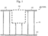
- FIGS. 1 and 2 are sectional views of the panel 100.
- the panel 100 is a plate provided with a honeycomb core 101 and two face materials 102 and is formed by sandwiching the honeycomb core 101 with the face materials 102.
- the honeycomb core 101 is formed of an array of a plurality of polygonal columns (for example, hexagonal columns). Each polygonal column is cylindrical.
- the face materials 102 are adhered to the upper portion and the lower portion of the honeycomb core 101 with adhesive sheets. More specifically, the face materials 102 are made of aluminum or CFRP (Carbon Fiber Reinforced Plastic).
- the adhesive sheets are a sheet-type adhesive.
- An embedding hole 103 is formed in the panel 100 by a boring process using a drill or the like.
- the embedding hole 103 is a hole in which a component called an insert will be embedded.
- the depth of the embedding hole 103 is smaller than the thickness of the panel 100.
- the depth of the embedding hole 103 is almost half the thickness of the panel 100.
- the panel 100 is a honeycomb sandwich panel used in a structure such as an artificial satellite, a flying object, and an in-vehicle shelter.
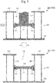
- two plates that is, a bottom plate 111 and a pushing plate 112 are placed to pile up on the bottom portion of the embedding hole 103.
- a sealer 113 which protrudes as being sandwiched by the two plates closes the gap between the two plates and a wall 104 of the honeycomb core 101.
- the sealing process is an operation of sealing a gap between a side portion of the bottom plate 111 and a flat surface of the honeycomb core 101.
- An nth step in the procedure of the sealing process will be referred to as "Sn" hereinafter where n is an integer.
- the fixing process is an operation of fixing an insert 120 in the embedding hole 103.
- An nth step in the procedure of the fixing process will be referred to as "Fn" hereinafter.
- FIG. 3 illustrates the first step (S1) and the second step (S2) of the sealing process.
- the bottom plate 111 is placed on the bottom portion of the embedding hole 103.
- a gap forms between the side portion of the bottom plate 111 and a wall surface 105 of the honeycomb core 101.
- the bottom plate 111 is preferably made of a thin, lightweight, and rigid material.
- the bottom plate 111 is a plate made of GFRP (Glass Fiber Reinforced Plastics).
- a flat surface of the bottom plate 111 has a shape and size that match the inlet of the embedding hole 103. For example, if the inlet of the embedding hole 103 is circular, the flat surface of the bottom plate 111 is circular. If the diameter of the inlet of the embedding hole 103 is 1 cm (centimeter), the diameter of the flat surface of the bottom plate 111 is 1 cm or slightly shorter than 1 cm.
- the sealer 113 is applied to an upper surface of the bottom plate 111.
- the sealer 113 is an adhesive to close the gap between the side portion of the bottom plate 111 and the wall surface of the honeycomb core 101.
- the sealer 113 is a cyanoacrylate-based adhesive or an acrylic-based adhesive.
- the sealer 113 is a hybrid type adhesive being a mixture of a cyanoacrylate-based adhesive and an acrylic-based adhesive.
- a rapid-hardening instant adhesive may be preferably used as the sealer 113. This is to shorten the time required for processing the panel 100 by shortening the time taken until hardening. Note that the time taken until the sealer 113 hardens is longer than the time taken until the subsequent fifth step (S5) is performed.
- FIG. 4 illustrates the third step (S3) and the fourth step (S4) of the sealing process.
- the pushing plate 112 is placed on the sealer 113 applied to the upper surface of the bottom plate 111.
- the pushing plate 112 is desirably made of a thin, lightweight, and rigid material like the bottom plate 111 is.
- the flat surface of the pushing plate 112 has a shape and size that matches the inlet of the embedding hole 103, like the flat surface of the bottom plate 111 does.
- the pushing plate 112 and the bottom plate 111 are identical.
- a rod member 114 is inserted in the embedding hole 103.
- FIG. 5 illustrates the fifth step (S5) of the sealing process.
- the pushing plate 112 is pushed by the rod member 114.
- the pushing plate 112 is pressed against the sealer 113 applied to the upper surface of the bottom plate 111.
- the sealer 113 protrudes into the gap between the side portion of the bottom plate 111 and the wall surface 105 of the honeycomb core 101. Consequently, the gap is closed with the sealer 113.
- FIG. 6 illustrates the first step (F1) and the second step (F2) of the fixing process.
- a temporary-fixing adhesive is applied to the upper surface of the pushing plate 112 and the insert 120 is embedded in the embedding hole 103.
- the insert 120 is a metal component to serve as an interface for connecting a component such as a structure member or an on-board component to the panel 100.
- the injection hole 121 for injecting a filler 122 is formed in an upper portion of the insert 120.
- the flat surface of the upper portion of the insert 120 has a shape and size to match the inlet of the embedding hole 103 as the flat surface of the bottom plate 111 does.
- the flat surface of the lower portion of the insert 120 has a shape and size that are different from those of the inlet of the embedding hole 103. Note that the flat surface of the lower portion of the insert 120 is smaller than the inlet of the embedding hole 103.
- the temporary-fixing adhesive is an adhesive for temporarily fixing the insert 120.
- the temporary-fixing adhesive is an adhesive of the same type as the sealer 113.
- a distal end of a syringe 130 containing the filler 122 is inserted in an injection hole 121.
- the filler 122 is an adhesive for fixing the insert 120 to the embedding hole 103.
- the filler 122 is a two-component mixture epoxy-based adhesive that uses a high-viscosity main agent and a low-viscosity hardening agent.
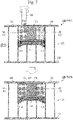
- FIG. 7 illustrates the third step (F3) of the fixing process.
- the filler 122 is injected into the embedding hole 103 from the syringe 130.
- the embedding hole 103 is closed with the filler 122.
- the insert 120 is fixed to the embedding hole 103.
- the filler 122 does not fill a portion below the bottom plate 111.
- the bottom plate 111 must be fixed to the bottom portion of the embedding hole 103 with the adhesive so that the bottom plate 111 will not move when spreading the sealer 113. Therefore, the operation cannot be carried out until the adhesive hardens and the bottom plate 111 is fixed. As a result, the sealing process becomes time consuming.
- Embodiment 1 in order to close the gap between the side portion of the bottom plate 111 and the wall surface of the honeycomb core 101 with the sealer 113, the pushing plate 112 is pressed against the sealer 113 applied to the upper surface of the bottom plate 111, thereby causing the sealer 113 to protrude into the gap. Namely, since the gap can be closed by pressing the pushing plate 112 against the sealer 113, the operation is very easy.
- the bottom plate 111 need not be fixed when pressing the pushing plate 112 against the sealer 113. Hence, the time taken for the sealing process can be shortened.
- Embodiment 1 Concerning an embodiment in which a pushing plate is pressed against sealer by an insert instead of a rod member, its difference from Embodiment 1 will mainly be described with reference to FIG. 8 .
- the configuration of a panel 100 is the same as that of Embodiment 1.
- the first step (S1) to the third step (S3) are the same as those of Embodiment 1.
- FIG. 8 illustrates the fourth step (S4) and the fifth step (S5) of the sealing process.
- a temporary-fixing adhesive 115 is applied to the upper surface of a pushing plate 112, and an insert 120 is placed on the preliminary fixing adhesive 115.
- the insert 120 is pushed into an embedding hole 103. That is, the insert 120 is embedded in the embedding hole 103.
- the pushing plate 112 is pressed against a sealer 113 applied to the upper surface of a bottom plate 111. Then, the sealer 113 protrudes into the gap between the side portion of the bottom plate 111 and the wall surface 105 of the honeycomb core 101. As a result, the gap is closed with the sealer 113.
- the procedure of the fixing process is the same as that of Embodiment 1.
- the sealing process can be carried out without using a rod member 114. That is, the sealing process is further facilitated.
- Embodiment 1 Concerning an embodiment in which a pushing plate adhered to the bottom surface of an insert is pressed against a sealer, its difference from Embodiment 1 will mainly be described with reference to FIG. 9 .
- the configuration of a panel 100 is the same as that of Embodiment 1.
- the first step (S1) to the third step (S3) are the same as those of Embodiment 1.
- FIG. 9 illustrates the fourth step (S4) and the fifth step (S5).
- a pushing plate 112 is adhered to the bottom surface of an insert 120, and the insert 120 is placed on a sealer 113 applied to the upper surface of a bottom plate 111.
- the insert 120 is pushed into an embedding hole 103. That is, the insert 120 is embedded in the embedding hole 103.
- the pushing plate 112 is pressed against the sealer 113 applied to the upper surface of the bottom plate 111. Then, the sealer 113 protrudes into the gap between the side portion of the bottom plate 111 and a wall surface 105 of a honeycomb core 101. As a result, the gap is closed with the sealer 113.
- the procedure of the fixing process is the same as that in Embodiment 1.
- the sealing process can be carried out without using a rod member 114. That is, the sealing process is further facilitated.
- Embodiment 1 Concerning an example in which a bottom portion of an insert is pressed as a pushing plate against a sealer, its difference from Embodiment 1 will mainly be described with reference to FIG. 10 .
- the first step (S1) and the second step (S2) are the same as those of Embodiment 1.
- FIG. 10 illustrates the third step (S3) and the fourth step (S4).
- an insert 120 is placed on a sealer 113 applied to the upper surface of a bottom plate 111.
- the bottom surface of the insert 120 has a shape and size that match the inlet of an embedding hole 103.
- the insert 120 is pushed into the embedding hole 103. That is, the insert 120 is embedded in the embedding hole 103.
- the bottom portion of the insert 120 is pressed as a pushing plate against the sealer 113 applied to the upper surface of the bottom plate 111. Then, the sealer 113 protrudes into the gap between the side portion of the bottom plate 111 and a wall surface 105 of a honeycomb core 101. As a result, the gap is closed with the sealer 113.
- the procedure of the fixing process is the same as that in Embodiment 1.
- the bottom surface of the insert 120 has the shape and size that match the inlet of the syringe 130, it is possible to cause the sealer 113 to protrude sufficiently into the gap without specially preparing a pushing plate 112. Accordingly, the sealing process can be carried out without specially preparing the pushing plate 112. Furthermore, the number of steps of the sealing process can be decreased.
- the procedure of the panel processing method may be performed either by humans or by machines. Namely, an operator may perform each step of the panel processing method, or a panel processing device may carry out each step of the panel processing method.
- the procedure of the panel processing method may be performed by a combination of humans and machines. Namely, the operator may perform some steps, and the panel processing device may perform the remaining steps.
- the panel processing device is a device fabricated to process the panel 100 according to the panel processing method.
Landscapes
- Engineering & Computer Science (AREA)
- General Engineering & Computer Science (AREA)
- Mechanical Engineering (AREA)
- Laminated Bodies (AREA)
- Standing Axle, Rod, Or Tube Structures Coupled By Welding, Adhesion, Or Deposition (AREA)
- Application Of Or Painting With Fluid Materials (AREA)
- Adhesives Or Adhesive Processes (AREA)
- Panels For Use In Building Construction (AREA)
Description
- The present invention relates to a technique of performing a sealing process on a panel that employs a honeycomb core.
- A structure such as an artificial satellite, a flying object, and an in-vehicle shelter often uses a lightweight, high-rigidity honeycomb sandwich panel.
- A honeycomb sandwich panel is a structure in which a face material is adhered to each of the two surfaces of a honeycomb core with a sheet-type adhesive. An insert is embedded in the honeycomb sandwich panel.
- The insert is an interface for connecting a component such as a structure member or an on-board apparatus. The insert is fixed to the honeycomb sandwich panel when a hole in which the insert is embedded is filled with a filler.
- The insert is temporarily fixed to the honeycomb sandwich panel before the filler is charged.
- Patent document
DE 28 34 237 B is considered relevant and relates to a method of fixing an insert to a honeycomb core panel. Firstly, a hole is drilled into the cover layer such as a disc at the bottom. Thereafter, a cold-curing adhesive is poured into the hole. The insert is then pressed into the hole in order to produce an adhesive film on all sides by pushing the adhesive. - Patent Literature 1:
JP 2001-140 362 A - Patent Literature 1 discloses a method of filling an insert-embedded hole with a filler.
- If the quantity of filler for filling is large, the honeycomb sandwich panel is heavy. Therefore, the quantity of filler for filling is preferably small.
- It is an object of the present invention to reduce the quantity of filler to fill a hole in which an insert is embedded.
- A panel processing method of the present invention is set out in the appended independent claims. Advantageous further developments of the invention are set forth in the dependent claims.
- According to the present invention, it is possible to close a gap between a side portion of a bottom plate placed on a bottom portion of an embedding hole and a side surface of a honeycomb core located around the embedding hole. As a result, the filler will not fill a portion below the bottom plate, so that the quantity of filler for filling is decreased.
-
- FIG. 1
- is a sectional view of a
panel 100 according to Embodiment 1. - FIG. 2
- is a sectional view of the
panel 100 after a sealing process in Embodiment 1. - FIG. 3
- is a diagram illustrating the first step (S1) and the second step (S2) of a panel processing method in Embodiment 1.
- FIG. 4
- is a diagram illustrating the third step (S3) and the fourth step (S4) of the panel processing method in Embodiment 1.
- FIG. 5
- is a diagram illustrating the fifth step (S5) of the panel processing method in Embodiment 1.
- FIG. 6
- is a diagram illustrating the first step (F1) and the second step (F2) of a panel fixing method in Embodiment 1.
- FIG 7
- is a diagram illustrating the third step (F3) of the panel fixing method in Embodiment 1.
- FIG. 8
- is a diagram illustrating the fourth step (S4) and the fifth step (S5) of a panel processing method in Embodiment 2.
- FIG. 9
- is a diagram illustrating the fourth step (S4) and the fifth step (S5) of a panel processing method in Embodiment 3.
- FIG 10
- is a diagram illustrating the third step (S3) and the fourth step (S4) of a panel processing method forming a part of the invention.
- In the embodiments and drawings, the same elements or mutually corresponding elements are denoted by the same reference numeral. An explanation of the elements denoted by the same reference numeral will be omitted or simplified appropriately.
- An embodiment in which a sealing process is performed on a panel that employs a honeycomb core will be described with reference to
FIGS. 1 to 7 . - A configuration of a
panel 100 will be described with reference toFIGS. 1 and2 .FIGS. 1 and2 are sectional views of thepanel 100. - As illustrated in
FIG. 1 , thepanel 100 is a plate provided with ahoneycomb core 101 and twoface materials 102 and is formed by sandwiching thehoneycomb core 101 with theface materials 102. - The
honeycomb core 101 is formed of an array of a plurality of polygonal columns (for example, hexagonal columns). Each polygonal column is cylindrical. - The
face materials 102 are adhered to the upper portion and the lower portion of thehoneycomb core 101 with adhesive sheets. More specifically, theface materials 102 are made of aluminum or CFRP (Carbon Fiber Reinforced Plastic). The adhesive sheets are a sheet-type adhesive. - An
embedding hole 103 is formed in thepanel 100 by a boring process using a drill or the like. - The
embedding hole 103 is a hole in which a component called an insert will be embedded. - The depth of the
embedding hole 103 is smaller than the thickness of thepanel 100. For example, the depth of theembedding hole 103 is almost half the thickness of thepanel 100. - For example, the
panel 100 is a honeycomb sandwich panel used in a structure such as an artificial satellite, a flying object, and an in-vehicle shelter. - As illustrated in
FIG. 2 , two plates, that is, abottom plate 111 and a pushingplate 112 are placed to pile up on the bottom portion of the embeddinghole 103. - A
sealer 113 which protrudes as being sandwiched by the two plates closes the gap between the two plates and awall 104 of thehoneycomb core 101. - As a procedure of the panel processing method of processing the
panel 100, a procedure of a sealing process and a procedure of a fixing process will be described. - The sealing process is an operation of sealing a gap between a side portion of the
bottom plate 111 and a flat surface of thehoneycomb core 101. An nth step in the procedure of the sealing process will be referred to as "Sn" hereinafter where n is an integer. - The fixing process is an operation of fixing an
insert 120 in the embeddinghole 103. An nth step in the procedure of the fixing process will be referred to as "Fn" hereinafter. -
FIG. 3 illustrates the first step (S1) and the second step (S2) of the sealing process. - In the first step (S1), the
bottom plate 111 is placed on the bottom portion of the embeddinghole 103. A gap forms between the side portion of thebottom plate 111 and awall surface 105 of thehoneycomb core 101. - The
bottom plate 111 is preferably made of a thin, lightweight, and rigid material. For example, thebottom plate 111 is a plate made of GFRP (Glass Fiber Reinforced Plastics). - A flat surface of the
bottom plate 111 has a shape and size that match the inlet of the embeddinghole 103. For example, if the inlet of the embeddinghole 103 is circular, the flat surface of thebottom plate 111 is circular. If the diameter of the inlet of the embeddinghole 103 is 1 cm (centimeter), the diameter of the flat surface of thebottom plate 111 is 1 cm or slightly shorter than 1 cm. - In the second step (S2), the
sealer 113 is applied to an upper surface of thebottom plate 111. - The
sealer 113 is an adhesive to close the gap between the side portion of thebottom plate 111 and the wall surface of thehoneycomb core 101. For example, thesealer 113 is a cyanoacrylate-based adhesive or an acrylic-based adhesive. Alternatively, thesealer 113 is a hybrid type adhesive being a mixture of a cyanoacrylate-based adhesive and an acrylic-based adhesive. - In particular, a rapid-hardening instant adhesive may be preferably used as the
sealer 113. This is to shorten the time required for processing thepanel 100 by shortening the time taken until hardening. Note that the time taken until thesealer 113 hardens is longer than the time taken until the subsequent fifth step (S5) is performed. -
FIG. 4 illustrates the third step (S3) and the fourth step (S4) of the sealing process. - In the third step (S3), the pushing
plate 112 is placed on thesealer 113 applied to the upper surface of thebottom plate 111. - The pushing
plate 112 is desirably made of a thin, lightweight, and rigid material like thebottom plate 111 is. - The flat surface of the pushing
plate 112 has a shape and size that matches the inlet of the embeddinghole 103, like the flat surface of thebottom plate 111 does. - For example, the pushing
plate 112 and thebottom plate 111 are identical. - In the fourth step (S4), a
rod member 114 is inserted in the embeddinghole 103. -
FIG. 5 illustrates the fifth step (S5) of the sealing process. - In the fifth step (S5), the pushing
plate 112 is pushed by therod member 114. - Accordingly, the pushing
plate 112 is pressed against thesealer 113 applied to the upper surface of thebottom plate 111. Hence, thesealer 113 protrudes into the gap between the side portion of thebottom plate 111 and thewall surface 105 of thehoneycomb core 101. Consequently, the gap is closed with thesealer 113. -
FIG. 6 illustrates the first step (F1) and the second step (F2) of the fixing process. - In the first step (F1), a temporary-fixing adhesive is applied to the upper surface of the pushing
plate 112 and theinsert 120 is embedded in the embeddinghole 103. - The
insert 120 is a metal component to serve as an interface for connecting a component such as a structure member or an on-board component to thepanel 100. - The
injection hole 121 for injecting afiller 122 is formed in an upper portion of theinsert 120. - The flat surface of the upper portion of the
insert 120 has a shape and size to match the inlet of the embeddinghole 103 as the flat surface of thebottom plate 111 does. The flat surface of the lower portion of theinsert 120 has a shape and size that are different from those of the inlet of the embeddinghole 103. Note that the flat surface of the lower portion of theinsert 120 is smaller than the inlet of the embeddinghole 103. - The temporary-fixing adhesive is an adhesive for temporarily fixing the
insert 120. For example, the temporary-fixing adhesive is an adhesive of the same type as thesealer 113. - In the second step (F2), a distal end of a
syringe 130 containing thefiller 122 is inserted in aninjection hole 121. - The
filler 122 is an adhesive for fixing theinsert 120 to the embeddinghole 103. For example, thefiller 122 is a two-component mixture epoxy-based adhesive that uses a high-viscosity main agent and a low-viscosity hardening agent. -
FIG. 7 illustrates the third step (F3) of the fixing process. - In the third step (F3), the
filler 122 is injected into the embeddinghole 103 from thesyringe 130. - Thus, the embedding
hole 103 is closed with thefiller 122. As thefiller 122 hardens, theinsert 120 is fixed to the embeddinghole 103. - Since the gap between the side portion of the
bottom plate 111 and the side surface of thehoneycomb core 101 is filled with thesealer 113, thefiller 122 does not fill a portion below thebottom plate 111. - It is possible to fill the gap between the side portion of the
bottom plate 111 and the wall surface of thehoneycomb core 101. As a result, thefiller 122 will not fill the portion below thebottom plate 111, and accordingly the quantity offiller 122 for filling decreases. Hence, weight reduction of thepanel 100 can be achieved. - As an operation for closing the gap between the side portion of the
bottom plate 111 and the wall surface of thehoneycomb core 101 with thesealer 113, an operation of manually spreading thesealer 113 applied to the upper surface of thebottom plate 111 with using a tool may be possible. - This operation, however, is very difficult. The reason is, for example, as the shape of the gap differs depending on the position of the embedding
hole 103, the direction in which the gap is positioned and the size of the gap cannot be determined uniquely. - Also, the
bottom plate 111 must be fixed to the bottom portion of the embeddinghole 103 with the adhesive so that thebottom plate 111 will not move when spreading thesealer 113. Therefore, the operation cannot be carried out until the adhesive hardens and thebottom plate 111 is fixed. As a result, the sealing process becomes time consuming. - Meanwhile, in Embodiment 1, in order to close the gap between the side portion of the
bottom plate 111 and the wall surface of thehoneycomb core 101 with thesealer 113, the pushingplate 112 is pressed against thesealer 113 applied to the upper surface of thebottom plate 111, thereby causing thesealer 113 to protrude into the gap. Namely, since the gap can be closed by pressing the pushingplate 112 against thesealer 113, the operation is very easy. - The
bottom plate 111 need not be fixed when pressing the pushingplate 112 against thesealer 113. Hence, the time taken for the sealing process can be shortened. - Concerning an embodiment in which a pushing plate is pressed against sealer by an insert instead of a rod member, its difference from Embodiment 1 will mainly be described with reference to
FIG. 8 . - The configuration of a
panel 100 is the same as that of Embodiment 1. - In a sealing process, the first step (S1) to the third step (S3) are the same as those of Embodiment 1.
-
FIG. 8 illustrates the fourth step (S4) and the fifth step (S5) of the sealing process. - In the fourth step (S4), a temporary-fixing
adhesive 115 is applied to the upper surface of a pushingplate 112, and aninsert 120 is placed on thepreliminary fixing adhesive 115. - In the fifth step (S5), the
insert 120 is pushed into an embeddinghole 103. That is, theinsert 120 is embedded in the embeddinghole 103. - Hence, the pushing
plate 112 is pressed against asealer 113 applied to the upper surface of abottom plate 111. Then, thesealer 113 protrudes into the gap between the side portion of thebottom plate 111 and thewall surface 105 of thehoneycomb core 101. As a result, the gap is closed with thesealer 113. - The procedure of the fixing process is the same as that of Embodiment 1.
- As the pushing
plate 112 is pressed against thesealer 113 with using theinsert 120, the sealing process can be carried out without using arod member 114. That is, the sealing process is further facilitated. - Concerning an embodiment in which a pushing plate adhered to the bottom surface of an insert is pressed against a sealer, its difference from Embodiment 1 will mainly be described with reference to
FIG. 9 . - The configuration of a
panel 100 is the same as that of Embodiment 1. - In a sealing process, the first step (S1) to the third step (S3) are the same as those of Embodiment 1.
-
FIG. 9 illustrates the fourth step (S4) and the fifth step (S5). - In the fourth step (S4), a pushing
plate 112 is adhered to the bottom surface of aninsert 120, and theinsert 120 is placed on asealer 113 applied to the upper surface of abottom plate 111. - In the fifth step (S5), the
insert 120 is pushed into an embeddinghole 103. That is, theinsert 120 is embedded in the embeddinghole 103. - Hence, the pushing
plate 112 is pressed against thesealer 113 applied to the upper surface of thebottom plate 111. Then, thesealer 113 protrudes into the gap between the side portion of thebottom plate 111 and awall surface 105 of ahoneycomb core 101. As a result, the gap is closed with thesealer 113. - The procedure of the fixing process is the same as that in Embodiment 1.
- As the pushing
plate 112 is pressed against thesealer 113 with using theinsert 120, the sealing process can be carried out without using arod member 114. That is, the sealing process is further facilitated. - Concerning an example in which a bottom portion of an insert is pressed as a pushing plate against a sealer, its difference from Embodiment 1 will mainly be described with reference to
FIG. 10 . - The configuration of a
panel 100 before a sealing process is the same as that of Embodiment 1. - In the sealing process, the first step (S1) and the second step (S2) are the same as those of Embodiment 1.
-
FIG. 10 illustrates the third step (S3) and the fourth step (S4). - In the third step (S3), an
insert 120 is placed on asealer 113 applied to the upper surface of abottom plate 111. The bottom surface of theinsert 120 has a shape and size that match the inlet of an embeddinghole 103. - In the fourth step (S4), the
insert 120 is pushed into the embeddinghole 103. That is, theinsert 120 is embedded in the embeddinghole 103. - Hence, the bottom portion of the
insert 120 is pressed as a pushing plate against thesealer 113 applied to the upper surface of thebottom plate 111. Then, thesealer 113 protrudes into the gap between the side portion of thebottom plate 111 and awall surface 105 of ahoneycomb core 101. As a result, the gap is closed with thesealer 113. - The procedure of the fixing process is the same as that in Embodiment 1.
- As the bottom surface of the
insert 120 has the shape and size that match the inlet of thesyringe 130, it is possible to cause thesealer 113 to protrude sufficiently into the gap without specially preparing a pushingplate 112. Accordingly, the sealing process can be carried out without specially preparing the pushingplate 112. Furthermore, the number of steps of the sealing process can be decreased. - The procedure of the panel processing method may be performed either by humans or by machines. Namely, an operator may perform each step of the panel processing method, or a panel processing device may carry out each step of the panel processing method.
- The procedure of the panel processing method may be performed by a combination of humans and machines. Namely, the operator may perform some steps, and the panel processing device may perform the remaining steps.
- The panel processing device is a device fabricated to process the
panel 100 according to the panel processing method. - Each embodiment is an exemplification of a preferred mode and is not intended to restrict the technical scope of the present invention. Each embodiment may be practiced partially or in combination with another embodiment. The procedure of the panel processing method may be changed appropriately.
-
- 100
- panel
- 101
- honeycomb core
- 102
- face material
- 103
- embedding hole
- 104
- wall
- 105
- wall surface
- 111
- bottom plate
- 112
- pushing plate
- 113
- sealer
- 114
- rod member
- 115
- adhesive
- 120
- insert
- 121
- injection hole
- 122
- filler
- 130
- syringe
Claims (5)
- A panel processing method of processing a panel (100) that uses a honeycomb core (101), comprising:- placing a bottom plate (111) on a bottom portion of an embedding hole (103) which is a hole formed in the honeycomb core (101) and in which an insert (120) is to be embedded,- applying a sealer (113) for closing a gap between a side portion of the bottom plate (111) and a wall surface (105) of the honeycomb core to an upper surface of the bottom plate (111), and- pressing a pushing plate (112) against the sealer (113) so that the sealer (113) protrudes into the gap,- applying a temporary fixing adhesive to an upper surface of the pushing plate (112),- inserting an insert (120) in the embedded hole (130),- injecting a filler (122) from an upper portion of the insert (120), wherein the filler (122) is an adhesive utilised for fixing the insert (120) to the embedding hole (103).
- The panel processing method according to claim 1,
wherein each of a flat surface of the bottom plate (111) and a flat surface of the pushing plate (112) has a shape and a size that match an inlet of the embedding hole (103). - The panel processing method according to claim 1 or 2,
wherein the sealer (113) is applied to the upper surface of the bottom plate (111), thereafter the pushing plate (112) is placed on the sealer (113), and the pushing plate (112) is pushed with using a rod member (114), so that the pushing plate (112) is pressed against the sealer (113). - The panel processing method according to claim 1 or 2,
wherein the sealer (113) is applied to the upper surface of the bottom plate (111), thereafter the pushing plate (112) is placed on the sealer (113), and the insert (120) is embedded in the embedding hole (103), so that the pushing plate (112) is pressed against the sealer (113). - A panel processing method of processing a panel (100) that uses a honeycomb core (101), comprising:- placing a bottom plate (111) on a bottom portion of an embedding hole (103) which is a hole formed in the honeycomb core (101) and in which an insert (120) is to be embedded,- adhering a pushing plate (112) to a bottom surface of an insert (120) against the sealer (113)- applying a sealer (113) for closing a gap between a side portion of the bottom plate (111) and a wall surface (105) of the honeycomb core to an upper surface of the bottom plate (111),- inserting the insert (120) in the embedded hole (130), so that the pushing plate (112) is pressed against the sealer (113), and so that the sealer (113) protrudes into the gap,- injecting a filler (122) from an upper portion of the insert (120), wherein the filler (122) is an adhesive utilised for fixing the insert (120) to the embedding hole (103).
Applications Claiming Priority (1)
| Application Number | Priority Date | Filing Date | Title |
|---|---|---|---|
| PCT/JP2016/085784 WO2018100721A1 (en) | 2016-12-01 | 2016-12-01 | Panel processing method, panel, and panel processing device |
Publications (3)
| Publication Number | Publication Date |
|---|---|
| EP3549756A1 EP3549756A1 (en) | 2019-10-09 |
| EP3549756A4 EP3549756A4 (en) | 2019-12-04 |
| EP3549756B1 true EP3549756B1 (en) | 2022-05-04 |
Family
ID=62241281
Family Applications (1)
| Application Number | Title | Priority Date | Filing Date |
|---|---|---|---|
| EP16922840.0A Active EP3549756B1 (en) | 2016-12-01 | 2016-12-01 | Panel processing method |
Country Status (4)
| Country | Link |
|---|---|
| EP (1) | EP3549756B1 (en) |
| JP (1) | JP6570770B2 (en) |
| ES (1) | ES2915326T3 (en) |
| WO (1) | WO2018100721A1 (en) |
Families Citing this family (1)
| Publication number | Priority date | Publication date | Assignee | Title |
|---|---|---|---|---|
| CN115722421B (en) * | 2022-10-24 | 2026-01-13 | 无锡中卓智能科技股份有限公司 | V-shaped jig seat frame for automatic assembly combined grouting machine |
Family Cites Families (10)
| Publication number | Priority date | Publication date | Assignee | Title |
|---|---|---|---|---|
| DE2736132C2 (en) * | 1977-08-11 | 1981-12-17 | Messerschmitt-Bölkow-Blohm GmbH, 8000 München | Process for the production of sandwich components |
| DE2834237C2 (en) * | 1978-08-04 | 1980-05-22 | Messerschmitt-Boelkow-Blohm Gmbh, 8000 Muenchen | Method for installing inserts in lightweight sandwich panels |
| US5713706A (en) * | 1995-12-19 | 1998-02-03 | Shur-Lok Corporation | Plastic composite fastener for self-cutting and frictional welding |
| JPH11348157A (en) * | 1998-06-02 | 1999-12-21 | Fuji Heavy Ind Ltd | Insert-fitting method to honeycomb sandwich panel |
| JPH11348155A (en) * | 1998-06-02 | 1999-12-21 | Fuji Heavy Ind Ltd | Insert fitting method to honeycomb sandwich panel |
| JP2000215929A (en) * | 1999-01-26 | 2000-08-04 | Mitsubishi Electric Corp | Insert for grounding |
| JP2001140362A (en) | 1999-11-17 | 2001-05-22 | Mitsubishi Electric Corp | Insert filling method |
| US7981519B2 (en) * | 2008-04-11 | 2011-07-19 | United Technologies Corporation | Metallic doubler for repair of a gas turbine engine part |
| US9003662B2 (en) * | 2013-01-31 | 2015-04-14 | B/E Aerospace, Inc. | Insert and method for anchoring in a cored panel |
| PT3339659T (en) * | 2013-03-20 | 2022-03-29 | Ruag Schweiz Ag | Insert for load application and/or anchorage of various components into respectively onto a composite sandwich panel and method of producing a lightweight support structure comprising the same |
-
2016
- 2016-12-01 EP EP16922840.0A patent/EP3549756B1/en active Active
- 2016-12-01 ES ES16922840T patent/ES2915326T3/en active Active
- 2016-12-01 JP JP2018553609A patent/JP6570770B2/en active Active
- 2016-12-01 WO PCT/JP2016/085784 patent/WO2018100721A1/en not_active Ceased
Also Published As
| Publication number | Publication date |
|---|---|
| EP3549756A1 (en) | 2019-10-09 |
| JP6570770B2 (en) | 2019-09-04 |
| JPWO2018100721A1 (en) | 2019-04-11 |
| EP3549756A4 (en) | 2019-12-04 |
| ES2915326T3 (en) | 2022-06-21 |
| WO2018100721A1 (en) | 2018-06-07 |
Similar Documents
| Publication | Publication Date | Title |
|---|---|---|
| US11794928B2 (en) | Satellite deployer with externally adjustable payload restraint | |
| US3016578A (en) | Moldable insert panel and method of assembly | |
| CN105209768B (en) | Lightweight supporting structure, the method for manufacturing lightweight supporting structure, composite sandwich panel and the method for manufacturing composite sandwich panel | |
| EP2044268B1 (en) | Resin anchor with a compressible envelope containing curable products, at least one of which is sacheted | |
| US20140360129A1 (en) | Device for introducing a force into tension members made of fiber-reinforced flat-strip plastic lamellas | |
| EP3339659B1 (en) | Insert for load application and/or anchorage of various components into respectively onto a composite sandwich panel and method of producing a lightweight support structure comprising the same | |
| DE602007011836D1 (en) | DEVICE AND METHOD FOR PRODUCING FIBER-REINFORCED COMPOSITE STRUCTURES | |
| EP2565021A1 (en) | A curable assembly, a filler component and a method of forming a component from a curable assembly comprising a filler component | |
| CN101360919B (en) | Resin anchor with compressible envelope containing curable product | |
| EP3549756A1 (en) | Panel processing method, panel, and panel processing device | |
| RU2009128261A (en) | LOCAL PROCESSING OF REINFORCED FOAM AND PLASTIC PRODUCTS | |
| ES2233668T3 (en) | PROCEDURE FOR REINFORCING AN EXISTING METALLIC STRUCTURE, PROCEDURE FOR REINFORCING PIPES AND PROCEDURE FOR CONTRIBUTION OF PIPES FOR CONNECTION TO OLEODUCTS. | |
| KR101453214B1 (en) | Composite structure and method of manufacturing thereof | |
| US10519772B2 (en) | Construction element for creating a tunnel, tunnel comprising such an element and methods for constructing such an element and such a tunnel | |
| WO2013064205A1 (en) | Production method for an energy storage apparatus, and an energy storage apparatus which is produced by means of this method | |
| DE19958375A1 (en) | System for transferring force, especially in aircraft construction, consists of tubes connected by coaxial sleeve, first tube being glued to sleeve and gap between second tube and sleeve containing pressure medium | |
| US20230304900A1 (en) | Method for boring a cylindrical sample from 3d-printed structure | |
| DE102016002835A1 (en) | Dowels for fixing screws or the like in building parts | |
| JP3768349B2 (en) | Wall column reinforcement method | |
| EP2149655B1 (en) | Method for introducing sealing bodies in concrete wall anchoring holes | |
| Sidor | AMTPS Development at NASA | |
| US20170138073A1 (en) | Drywall repair system and method of drywall repair | |
| JP6955986B2 (en) | How to reinforce concrete structures | |
| EP3101077A1 (en) | Pre-processing method for adhering rubber layer to inner and outer surfaces of cylindrical object-of-adherence | |
| JP4346024B2 (en) | Disposal method of resin material |
Legal Events
| Date | Code | Title | Description |
|---|---|---|---|
| STAA | Information on the status of an ep patent application or granted ep patent |
Free format text: STATUS: THE INTERNATIONAL PUBLICATION HAS BEEN MADE |
|
| PUAI | Public reference made under article 153(3) epc to a published international application that has entered the european phase |
Free format text: ORIGINAL CODE: 0009012 |
|
| STAA | Information on the status of an ep patent application or granted ep patent |
Free format text: STATUS: REQUEST FOR EXAMINATION WAS MADE |
|
| 17P | Request for examination filed |
Effective date: 20190524 |
|
| AK | Designated contracting states |
Kind code of ref document: A1 Designated state(s): AL AT BE BG CH CY CZ DE DK EE ES FI FR GB GR HR HU IE IS IT LI LT LU LV MC MK MT NL NO PL PT RO RS SE SI SK SM TR |
|
| AX | Request for extension of the european patent |
Extension state: BA ME |
|
| A4 | Supplementary search report drawn up and despatched |
Effective date: 20191104 |
|
| RIC1 | Information provided on ipc code assigned before grant |
Ipc: B05D 3/12 20060101ALI20191028BHEP Ipc: B32B 3/12 20060101AFI20191028BHEP Ipc: C09J 5/00 20060101ALI20191028BHEP Ipc: F16B 5/01 20060101ALI20191028BHEP |
|
| DAV | Request for validation of the european patent (deleted) | ||
| DAX | Request for extension of the european patent (deleted) | ||
| STAA | Information on the status of an ep patent application or granted ep patent |
Free format text: STATUS: EXAMINATION IS IN PROGRESS |
|
| 17Q | First examination report despatched |
Effective date: 20201026 |
|
| GRAP | Despatch of communication of intention to grant a patent |
Free format text: ORIGINAL CODE: EPIDOSNIGR1 |
|
| STAA | Information on the status of an ep patent application or granted ep patent |
Free format text: STATUS: GRANT OF PATENT IS INTENDED |
|
| INTG | Intention to grant announced |
Effective date: 20211115 |
|
| GRAS | Grant fee paid |
Free format text: ORIGINAL CODE: EPIDOSNIGR3 |
|
| GRAA | (expected) grant |
Free format text: ORIGINAL CODE: 0009210 |
|
| STAA | Information on the status of an ep patent application or granted ep patent |
Free format text: STATUS: THE PATENT HAS BEEN GRANTED |
|
| AK | Designated contracting states |
Kind code of ref document: B1 Designated state(s): AL AT BE BG CH CY CZ DE DK EE ES FI FR GB GR HR HU IE IS IT LI LT LU LV MC MK MT NL NO PL PT RO RS SE SI SK SM TR |
|
| REG | Reference to a national code |
Ref country code: GB Ref legal event code: FG4D |
|
| REG | Reference to a national code |
Ref country code: CH Ref legal event code: EP |
|
| REG | Reference to a national code |
Ref country code: AT Ref legal event code: REF Ref document number: 1488600 Country of ref document: AT Kind code of ref document: T Effective date: 20220515 |
|
| REG | Reference to a national code |
Ref country code: DE Ref legal event code: R096 Ref document number: 602016071942 Country of ref document: DE |
|
| REG | Reference to a national code |
Ref country code: IE Ref legal event code: FG4D |
|
| REG | Reference to a national code |
Ref country code: ES Ref legal event code: FG2A Ref document number: 2915326 Country of ref document: ES Kind code of ref document: T3 Effective date: 20220621 |
|
| REG | Reference to a national code |
Ref country code: LT Ref legal event code: MG9D |
|
| REG | Reference to a national code |
Ref country code: NL Ref legal event code: MP Effective date: 20220504 |
|
| REG | Reference to a national code |
Ref country code: AT Ref legal event code: MK05 Ref document number: 1488600 Country of ref document: AT Kind code of ref document: T Effective date: 20220504 |
|
| PG25 | Lapsed in a contracting state [announced via postgrant information from national office to epo] |
Ref country code: SE Free format text: LAPSE BECAUSE OF FAILURE TO SUBMIT A TRANSLATION OF THE DESCRIPTION OR TO PAY THE FEE WITHIN THE PRESCRIBED TIME-LIMIT Effective date: 20220504 Ref country code: PT Free format text: LAPSE BECAUSE OF FAILURE TO SUBMIT A TRANSLATION OF THE DESCRIPTION OR TO PAY THE FEE WITHIN THE PRESCRIBED TIME-LIMIT Effective date: 20220905 Ref country code: NO Free format text: LAPSE BECAUSE OF FAILURE TO SUBMIT A TRANSLATION OF THE DESCRIPTION OR TO PAY THE FEE WITHIN THE PRESCRIBED TIME-LIMIT Effective date: 20220804 Ref country code: NL Free format text: LAPSE BECAUSE OF FAILURE TO SUBMIT A TRANSLATION OF THE DESCRIPTION OR TO PAY THE FEE WITHIN THE PRESCRIBED TIME-LIMIT Effective date: 20220504 Ref country code: LT Free format text: LAPSE BECAUSE OF FAILURE TO SUBMIT A TRANSLATION OF THE DESCRIPTION OR TO PAY THE FEE WITHIN THE PRESCRIBED TIME-LIMIT Effective date: 20220504 Ref country code: HR Free format text: LAPSE BECAUSE OF FAILURE TO SUBMIT A TRANSLATION OF THE DESCRIPTION OR TO PAY THE FEE WITHIN THE PRESCRIBED TIME-LIMIT Effective date: 20220504 Ref country code: GR Free format text: LAPSE BECAUSE OF FAILURE TO SUBMIT A TRANSLATION OF THE DESCRIPTION OR TO PAY THE FEE WITHIN THE PRESCRIBED TIME-LIMIT Effective date: 20220805 Ref country code: FI Free format text: LAPSE BECAUSE OF FAILURE TO SUBMIT A TRANSLATION OF THE DESCRIPTION OR TO PAY THE FEE WITHIN THE PRESCRIBED TIME-LIMIT Effective date: 20220504 Ref country code: BG Free format text: LAPSE BECAUSE OF FAILURE TO SUBMIT A TRANSLATION OF THE DESCRIPTION OR TO PAY THE FEE WITHIN THE PRESCRIBED TIME-LIMIT Effective date: 20220804 Ref country code: AT Free format text: LAPSE BECAUSE OF FAILURE TO SUBMIT A TRANSLATION OF THE DESCRIPTION OR TO PAY THE FEE WITHIN THE PRESCRIBED TIME-LIMIT Effective date: 20220504 |
|
| PG25 | Lapsed in a contracting state [announced via postgrant information from national office to epo] |
Ref country code: RS Free format text: LAPSE BECAUSE OF FAILURE TO SUBMIT A TRANSLATION OF THE DESCRIPTION OR TO PAY THE FEE WITHIN THE PRESCRIBED TIME-LIMIT Effective date: 20220504 Ref country code: PL Free format text: LAPSE BECAUSE OF FAILURE TO SUBMIT A TRANSLATION OF THE DESCRIPTION OR TO PAY THE FEE WITHIN THE PRESCRIBED TIME-LIMIT Effective date: 20220504 Ref country code: LV Free format text: LAPSE BECAUSE OF FAILURE TO SUBMIT A TRANSLATION OF THE DESCRIPTION OR TO PAY THE FEE WITHIN THE PRESCRIBED TIME-LIMIT Effective date: 20220504 Ref country code: IS Free format text: LAPSE BECAUSE OF FAILURE TO SUBMIT A TRANSLATION OF THE DESCRIPTION OR TO PAY THE FEE WITHIN THE PRESCRIBED TIME-LIMIT Effective date: 20220904 |
|
| PG25 | Lapsed in a contracting state [announced via postgrant information from national office to epo] |
Ref country code: SM Free format text: LAPSE BECAUSE OF FAILURE TO SUBMIT A TRANSLATION OF THE DESCRIPTION OR TO PAY THE FEE WITHIN THE PRESCRIBED TIME-LIMIT Effective date: 20220504 Ref country code: SK Free format text: LAPSE BECAUSE OF FAILURE TO SUBMIT A TRANSLATION OF THE DESCRIPTION OR TO PAY THE FEE WITHIN THE PRESCRIBED TIME-LIMIT Effective date: 20220504 Ref country code: RO Free format text: LAPSE BECAUSE OF FAILURE TO SUBMIT A TRANSLATION OF THE DESCRIPTION OR TO PAY THE FEE WITHIN THE PRESCRIBED TIME-LIMIT Effective date: 20220504 Ref country code: EE Free format text: LAPSE BECAUSE OF FAILURE TO SUBMIT A TRANSLATION OF THE DESCRIPTION OR TO PAY THE FEE WITHIN THE PRESCRIBED TIME-LIMIT Effective date: 20220504 Ref country code: DK Free format text: LAPSE BECAUSE OF FAILURE TO SUBMIT A TRANSLATION OF THE DESCRIPTION OR TO PAY THE FEE WITHIN THE PRESCRIBED TIME-LIMIT Effective date: 20220504 Ref country code: CZ Free format text: LAPSE BECAUSE OF FAILURE TO SUBMIT A TRANSLATION OF THE DESCRIPTION OR TO PAY THE FEE WITHIN THE PRESCRIBED TIME-LIMIT Effective date: 20220504 |
|
| REG | Reference to a national code |
Ref country code: DE Ref legal event code: R097 Ref document number: 602016071942 Country of ref document: DE |
|
| PLBE | No opposition filed within time limit |
Free format text: ORIGINAL CODE: 0009261 |
|
| STAA | Information on the status of an ep patent application or granted ep patent |
Free format text: STATUS: NO OPPOSITION FILED WITHIN TIME LIMIT |
|
| PG25 | Lapsed in a contracting state [announced via postgrant information from national office to epo] |
Ref country code: AL Free format text: LAPSE BECAUSE OF FAILURE TO SUBMIT A TRANSLATION OF THE DESCRIPTION OR TO PAY THE FEE WITHIN THE PRESCRIBED TIME-LIMIT Effective date: 20220504 |
|
| 26N | No opposition filed |
Effective date: 20230207 |
|
| PG25 | Lapsed in a contracting state [announced via postgrant information from national office to epo] |
Ref country code: SI Free format text: LAPSE BECAUSE OF FAILURE TO SUBMIT A TRANSLATION OF THE DESCRIPTION OR TO PAY THE FEE WITHIN THE PRESCRIBED TIME-LIMIT Effective date: 20220504 |
|
| P01 | Opt-out of the competence of the unified patent court (upc) registered |
Effective date: 20230512 |
|
| REG | Reference to a national code |
Ref country code: CH Ref legal event code: PL |
|
| GBPC | Gb: european patent ceased through non-payment of renewal fee |
Effective date: 20221201 |
|
| REG | Reference to a national code |
Ref country code: BE Ref legal event code: MM Effective date: 20221231 |
|
| PG25 | Lapsed in a contracting state [announced via postgrant information from national office to epo] |
Ref country code: LU Free format text: LAPSE BECAUSE OF NON-PAYMENT OF DUE FEES Effective date: 20221201 |
|
| PG25 | Lapsed in a contracting state [announced via postgrant information from national office to epo] |
Ref country code: LI Free format text: LAPSE BECAUSE OF NON-PAYMENT OF DUE FEES Effective date: 20221231 Ref country code: IE Free format text: LAPSE BECAUSE OF NON-PAYMENT OF DUE FEES Effective date: 20221201 Ref country code: GB Free format text: LAPSE BECAUSE OF NON-PAYMENT OF DUE FEES Effective date: 20221201 Ref country code: CH Free format text: LAPSE BECAUSE OF NON-PAYMENT OF DUE FEES Effective date: 20221231 |
|
| PG25 | Lapsed in a contracting state [announced via postgrant information from national office to epo] |
Ref country code: BE Free format text: LAPSE BECAUSE OF NON-PAYMENT OF DUE FEES Effective date: 20221231 |
|
| PG25 | Lapsed in a contracting state [announced via postgrant information from national office to epo] |
Ref country code: IT Free format text: LAPSE BECAUSE OF FAILURE TO SUBMIT A TRANSLATION OF THE DESCRIPTION OR TO PAY THE FEE WITHIN THE PRESCRIBED TIME-LIMIT Effective date: 20220504 |
|
| PG25 | Lapsed in a contracting state [announced via postgrant information from national office to epo] |
Ref country code: HU Free format text: LAPSE BECAUSE OF FAILURE TO SUBMIT A TRANSLATION OF THE DESCRIPTION OR TO PAY THE FEE WITHIN THE PRESCRIBED TIME-LIMIT; INVALID AB INITIO Effective date: 20161201 |
|
| PG25 | Lapsed in a contracting state [announced via postgrant information from national office to epo] |
Ref country code: CY Free format text: LAPSE BECAUSE OF FAILURE TO SUBMIT A TRANSLATION OF THE DESCRIPTION OR TO PAY THE FEE WITHIN THE PRESCRIBED TIME-LIMIT Effective date: 20220504 |
|
| PG25 | Lapsed in a contracting state [announced via postgrant information from national office to epo] |
Ref country code: MK Free format text: LAPSE BECAUSE OF FAILURE TO SUBMIT A TRANSLATION OF THE DESCRIPTION OR TO PAY THE FEE WITHIN THE PRESCRIBED TIME-LIMIT Effective date: 20220504 |
|
| PG25 | Lapsed in a contracting state [announced via postgrant information from national office to epo] |
Ref country code: MC Free format text: LAPSE BECAUSE OF FAILURE TO SUBMIT A TRANSLATION OF THE DESCRIPTION OR TO PAY THE FEE WITHIN THE PRESCRIBED TIME-LIMIT Effective date: 20220504 |
|
| PG25 | Lapsed in a contracting state [announced via postgrant information from national office to epo] |
Ref country code: TR Free format text: LAPSE BECAUSE OF FAILURE TO SUBMIT A TRANSLATION OF THE DESCRIPTION OR TO PAY THE FEE WITHIN THE PRESCRIBED TIME-LIMIT Effective date: 20220504 Ref country code: MC Free format text: LAPSE BECAUSE OF FAILURE TO SUBMIT A TRANSLATION OF THE DESCRIPTION OR TO PAY THE FEE WITHIN THE PRESCRIBED TIME-LIMIT Effective date: 20220504 |
|
| PG25 | Lapsed in a contracting state [announced via postgrant information from national office to epo] |
Ref country code: MT Free format text: LAPSE BECAUSE OF FAILURE TO SUBMIT A TRANSLATION OF THE DESCRIPTION OR TO PAY THE FEE WITHIN THE PRESCRIBED TIME-LIMIT Effective date: 20220504 |
|
| PG25 | Lapsed in a contracting state [announced via postgrant information from national office to epo] |
Ref country code: BG Free format text: LAPSE BECAUSE OF FAILURE TO SUBMIT A TRANSLATION OF THE DESCRIPTION OR TO PAY THE FEE WITHIN THE PRESCRIBED TIME-LIMIT Effective date: 20220504 |
|
| PG25 | Lapsed in a contracting state [announced via postgrant information from national office to epo] |
Ref country code: BG Free format text: LAPSE BECAUSE OF FAILURE TO SUBMIT A TRANSLATION OF THE DESCRIPTION OR TO PAY THE FEE WITHIN THE PRESCRIBED TIME-LIMIT Effective date: 20220504 |
|
| PGFP | Annual fee paid to national office [announced via postgrant information from national office to epo] |
Ref country code: DE Payment date: 20251028 Year of fee payment: 10 |
|
| PGFP | Annual fee paid to national office [announced via postgrant information from national office to epo] |
Ref country code: FR Payment date: 20251117 Year of fee payment: 10 |
|
| PGFP | Annual fee paid to national office [announced via postgrant information from national office to epo] |
Ref country code: ES Payment date: 20260108 Year of fee payment: 10 |