EP3549662A1 - Mischerbaugruppe - Google Patents
Mischerbaugruppe Download PDFInfo
- Publication number
- EP3549662A1 EP3549662A1 EP19166025.7A EP19166025A EP3549662A1 EP 3549662 A1 EP3549662 A1 EP 3549662A1 EP 19166025 A EP19166025 A EP 19166025A EP 3549662 A1 EP3549662 A1 EP 3549662A1
- Authority
- EP
- European Patent Office
- Prior art keywords
- coupling
- exhaust
- flange
- mixer
- coupling portion
- Prior art date
- Legal status (The legal status is an assumption and is not a legal conclusion. Google has not performed a legal analysis and makes no representation as to the accuracy of the status listed.)
- Granted
Links
Images



Classifications
-
- F—MECHANICAL ENGINEERING; LIGHTING; HEATING; WEAPONS; BLASTING
- F01—MACHINES OR ENGINES IN GENERAL; ENGINE PLANTS IN GENERAL; STEAM ENGINES
- F01N—GAS-FLOW SILENCERS OR EXHAUST APPARATUS FOR MACHINES OR ENGINES IN GENERAL; GAS-FLOW SILENCERS OR EXHAUST APPARATUS FOR INTERNAL-COMBUSTION ENGINES
- F01N3/00—Exhaust or silencing apparatus having means for purifying, rendering innocuous, or otherwise treating exhaust
- F01N3/08—Exhaust or silencing apparatus having means for purifying, rendering innocuous, or otherwise treating exhaust for rendering innocuous
- F01N3/10—Exhaust or silencing apparatus having means for purifying, rendering innocuous, or otherwise treating exhaust for rendering innocuous by thermal or catalytic conversion of noxious components of exhaust
- F01N3/24—Exhaust or silencing apparatus having means for purifying, rendering innocuous, or otherwise treating exhaust for rendering innocuous by thermal or catalytic conversion of noxious components of exhaust characterised by constructional aspects of converting apparatus
- F01N3/28—Construction of catalytic reactors
- F01N3/2892—Exhaust flow directors or the like, e.g. upstream of catalytic device
-
- B—PERFORMING OPERATIONS; TRANSPORTING
- B01—PHYSICAL OR CHEMICAL PROCESSES OR APPARATUS IN GENERAL
- B01F—MIXING, e.g. DISSOLVING, EMULSIFYING OR DISPERSING
- B01F25/00—Flow mixers; Mixers for falling materials, e.g. solid particles
- B01F25/10—Mixing by creating a vortex flow, e.g. by tangential introduction of flow components
-
- B—PERFORMING OPERATIONS; TRANSPORTING
- B01—PHYSICAL OR CHEMICAL PROCESSES OR APPARATUS IN GENERAL
- B01F—MIXING, e.g. DISSOLVING, EMULSIFYING OR DISPERSING
- B01F25/00—Flow mixers; Mixers for falling materials, e.g. solid particles
- B01F25/40—Static mixers
- B01F25/42—Static mixers in which the mixing is affected by moving the components jointly in changing directions, e.g. in tubes provided with baffles or obstructions
- B01F25/421—Static mixers in which the mixing is affected by moving the components jointly in changing directions, e.g. in tubes provided with baffles or obstructions by moving the components in a convoluted or labyrinthine path
- B01F25/423—Static mixers in which the mixing is affected by moving the components jointly in changing directions, e.g. in tubes provided with baffles or obstructions by moving the components in a convoluted or labyrinthine path by means of elements placed in the receptacle for moving or guiding the components
- B01F25/4231—Static mixers in which the mixing is affected by moving the components jointly in changing directions, e.g. in tubes provided with baffles or obstructions by moving the components in a convoluted or labyrinthine path by means of elements placed in the receptacle for moving or guiding the components using baffles
-
- B—PERFORMING OPERATIONS; TRANSPORTING
- B01—PHYSICAL OR CHEMICAL PROCESSES OR APPARATUS IN GENERAL
- B01F—MIXING, e.g. DISSOLVING, EMULSIFYING OR DISPERSING
- B01F25/00—Flow mixers; Mixers for falling materials, e.g. solid particles
- B01F25/40—Static mixers
- B01F25/42—Static mixers in which the mixing is affected by moving the components jointly in changing directions, e.g. in tubes provided with baffles or obstructions
- B01F25/43—Mixing tubes, e.g. wherein the material is moved in a radial or partly reversed direction
- B01F25/431—Straight mixing tubes with baffles or obstructions that do not cause substantial pressure drop; Baffles therefor
- B01F25/4315—Straight mixing tubes with baffles or obstructions that do not cause substantial pressure drop; Baffles therefor the baffles being deformed flat pieces of material
-
- F—MECHANICAL ENGINEERING; LIGHTING; HEATING; WEAPONS; BLASTING
- F01—MACHINES OR ENGINES IN GENERAL; ENGINE PLANTS IN GENERAL; STEAM ENGINES
- F01N—GAS-FLOW SILENCERS OR EXHAUST APPARATUS FOR MACHINES OR ENGINES IN GENERAL; GAS-FLOW SILENCERS OR EXHAUST APPARATUS FOR INTERNAL-COMBUSTION ENGINES
- F01N13/00—Exhaust or silencing apparatus characterised by constructional features
- F01N13/08—Other arrangements or adaptations of exhaust conduits
-
- F—MECHANICAL ENGINEERING; LIGHTING; HEATING; WEAPONS; BLASTING
- F01—MACHINES OR ENGINES IN GENERAL; ENGINE PLANTS IN GENERAL; STEAM ENGINES
- F01N—GAS-FLOW SILENCERS OR EXHAUST APPARATUS FOR MACHINES OR ENGINES IN GENERAL; GAS-FLOW SILENCERS OR EXHAUST APPARATUS FOR INTERNAL-COMBUSTION ENGINES
- F01N13/00—Exhaust or silencing apparatus characterised by constructional features
- F01N13/08—Other arrangements or adaptations of exhaust conduits
- F01N13/082—Other arrangements or adaptations of exhaust conduits of tailpipe, e.g. with means for mixing air with exhaust for exhaust cooling, dilution or evacuation
-
- F—MECHANICAL ENGINEERING; LIGHTING; HEATING; WEAPONS; BLASTING
- F01—MACHINES OR ENGINES IN GENERAL; ENGINE PLANTS IN GENERAL; STEAM ENGINES
- F01N—GAS-FLOW SILENCERS OR EXHAUST APPARATUS FOR MACHINES OR ENGINES IN GENERAL; GAS-FLOW SILENCERS OR EXHAUST APPARATUS FOR INTERNAL-COMBUSTION ENGINES
- F01N13/00—Exhaust or silencing apparatus characterised by constructional features
- F01N13/18—Construction facilitating manufacture, assembly, or disassembly
- F01N13/1838—Construction facilitating manufacture, assembly, or disassembly characterised by the type of connection between parts of exhaust or silencing apparatus, e.g. between housing and tubes, between tubes and baffles
- F01N13/1844—Mechanical joints
-
- F—MECHANICAL ENGINEERING; LIGHTING; HEATING; WEAPONS; BLASTING
- F01—MACHINES OR ENGINES IN GENERAL; ENGINE PLANTS IN GENERAL; STEAM ENGINES
- F01N—GAS-FLOW SILENCERS OR EXHAUST APPARATUS FOR MACHINES OR ENGINES IN GENERAL; GAS-FLOW SILENCERS OR EXHAUST APPARATUS FOR INTERNAL-COMBUSTION ENGINES
- F01N3/00—Exhaust or silencing apparatus having means for purifying, rendering innocuous, or otherwise treating exhaust
- F01N3/08—Exhaust or silencing apparatus having means for purifying, rendering innocuous, or otherwise treating exhaust for rendering innocuous
- F01N3/10—Exhaust or silencing apparatus having means for purifying, rendering innocuous, or otherwise treating exhaust for rendering innocuous by thermal or catalytic conversion of noxious components of exhaust
- F01N3/24—Exhaust or silencing apparatus having means for purifying, rendering innocuous, or otherwise treating exhaust for rendering innocuous by thermal or catalytic conversion of noxious components of exhaust characterised by constructional aspects of converting apparatus
- F01N3/28—Construction of catalytic reactors
-
- F—MECHANICAL ENGINEERING; LIGHTING; HEATING; WEAPONS; BLASTING
- F16—ENGINEERING ELEMENTS AND UNITS; GENERAL MEASURES FOR PRODUCING AND MAINTAINING EFFECTIVE FUNCTIONING OF MACHINES OR INSTALLATIONS; THERMAL INSULATION IN GENERAL
- F16L—PIPES; JOINTS OR FITTINGS FOR PIPES; SUPPORTS FOR PIPES, CABLES OR PROTECTIVE TUBING; MEANS FOR THERMAL INSULATION IN GENERAL
- F16L23/00—Flanged joints
- F16L23/04—Flanged joints the flanges being connected by members tensioned in the radial plane
-
- F—MECHANICAL ENGINEERING; LIGHTING; HEATING; WEAPONS; BLASTING
- F01—MACHINES OR ENGINES IN GENERAL; ENGINE PLANTS IN GENERAL; STEAM ENGINES
- F01N—GAS-FLOW SILENCERS OR EXHAUST APPARATUS FOR MACHINES OR ENGINES IN GENERAL; GAS-FLOW SILENCERS OR EXHAUST APPARATUS FOR INTERNAL-COMBUSTION ENGINES
- F01N2240/00—Combination or association of two or more different exhaust treating devices, or of at least one such device with an auxiliary device, not covered by indexing codes F01N2230/00 or F01N2250/00, one of the devices being
- F01N2240/20—Combination or association of two or more different exhaust treating devices, or of at least one such device with an auxiliary device, not covered by indexing codes F01N2230/00 or F01N2250/00, one of the devices being a flow director or deflector
Definitions
- the present invention relates to a mixer assembly that can be used in an exhaust system of a vehicle internal combustion engine to mix reactant injected in the exhaust gas discharged from an internal combustion engine with the exhaust gas.
- a mixer is integrated, which with a plurality of vane-like flow baffles a swirling of the exhaust gas flowing in the exhaust system and thus mixing effected with the injected reagent.
- Such mixers are generally constructed such that they are generally received in the interior of tubular exhaust gas guide elements of the exhaust system and are supported in their radially outer region thereto.
- Fig. 1 is one of the post-published German patent application DE 10 2016 120 171.5 known exhaust system for a vehicle internal combustion engine generally designated 10.
- the exhaust system 10 has in an upstream region 12 two adjoining, tubular exhaust gas guide elements 14, 16. These have in an abutment region 18 in each case a flange-like coupling portion 20 and 22, in which these, for example, by the flange-like coupling portions 20, 22 by cross-bolt are firmly connected.
- Support member 24 positioned a generally designated 26 mixer assembly and thus by means of, for example, this sweeping bolt with the two exhaust guide elements 14, 16 and their flange coupling sections 20, 22 defined in the adjoining region 18 on the exhaust system 10.
- the abutment region 18 is located downstream of a reagent injection arrangement, by means of which a reagent, for example a urea / water solution, can be injected into the exhaust stream. Downstream of the abutment region 18, adjacent to the exhaust guide member 16, there is provided a catalyst assembly, generally designated 28, in which the mixture of exhaust gas and reactant is subjected to selective catalytic reduction so as to reduce the level of nitrogen oxide in the exhaust gas. Via a further exhaust gas guide element 30, the exhaust gas passes to an exhaust muffler 32, from which this is discharged, for example via two tailpipes 34, 36 to the outside.
- a reagent for example a urea / water solution
- the Fig. 2 shows in a perspective view of the mixer assembly 26.
- the mixer assembly 26 includes the already mentioned preferably plate-like support member 24, the circumferential contour, for example, may substantially correspond to the peripheral contour of the flange-like coupling portion 22.
- the flange-like coupling portion 22 is preferably provided as Blechumformteil and plate-like support member 24 formed with a ring-like structure and has at two opposite peripheral regions radial extensions with openings 38, 40, through which the two flange coupling portions 20, 22 and thus the exhaust guide elements 14, 16 connecting bolts can be performed.
- the carrier element 24 or the mixer assembly 26 as a preassembly assembly with the exhaust gas guide element 16
- the carrier element 24 for example, in the two above-mentioned peripheral areas fixing tabs 42 which are bent or after Positioning the mixer assembly 26 are bent on the exhaust guide member 16 that they engage behind the flange-like coupling portion 22 and thus fix the mixer assembly 26 thereto.
- the assembled assembly can then be assembled in a simple manner with the exhaust guide element 14 by its flange-like coupling portion is attached to the flange-like coupling portion 22 and the support member 24 and connected by screwing it.
- each of the counter-holding portions 46 includes an inwardly projecting tab-like holding portion 50.
- Each tab-like holding portion 50 is formed substantially U-shaped and has an outer U-leg 52, an inner U-leg 54 and a connecting portion connecting them.
- the U-shaped holding portions 50 are shaped so that the holding portions 50 in the direction of a recognizable inflow side 58 of the mixer body 48, ie in the upstream direction, are open and to a hidden downstream side 60 of the mixer body 48, ie in the downstream direction, in particular by the Connection area are completed.
- Each of the holding portions 50 is designed substantially hook-like and thus enables a stable mounting of the mixer body 48 on the carrier element 24.
- the U-leg 52 extends from the carrier element body 44 substantially in the direction of a mixer longitudinal axis and in the direction of the outflow side 60 of the mixer body 48th to, while the U-leg 54 extends from the connecting portion 56 substantially parallel to the U-leg 52 in the direction of the inflow side 58 of the mixer body 48 to.
- the mixer body 48 comprises a plurality of circumferentially successive and with respect to the mixer longitudinal axis L, for example in These extend from a central body portion 64 of the mixer body 48 and extend radially outwardly to a preferably on the upstream side 58 of the flow deflecting elements 62 subsequent annular connecting portion 66.
- the mixer body 48 may be connected to the central body portion 64, the scoop-like flow deflecting elements 62 and the annular connecting portion 66 may be provided as an integral component, for example as a metal casting component.
- the ring-like connection region 66 provides holding regions 70 configured in the form of a holding web 68 for cooperation, each with a counter-holding region 46 of the carrier element 24, in its regions extending between the circumferentially directly successive flow deflecting elements 62 and interconnecting them.
- These holding regions 70 designed as holding webs 68 can be introduced into a holding region receiving space 72 provided by the U-shaped holding sections 50 of the counter-holding regions 46, such that the holding sections 50 on the one hand engage the holding regions 70 cooperating therewith with respect to the mixer longitudinal axis L from radially outward overlap radially inside and axially overlap the holding portions 70 with the inner U-legs 54 in the direction of the mixer longitudinal axis.
- the holding webs 68 thus located at least in regions within the holding area receiving spaces can thus not move out of the holding sections 50 in the direction of the outflow side 60 of the mixer body 48, ie are secured against excessive axial movement, and are substantially due to cooperation with the inner U-legs 54 also radially centered.
- a defined positioning of the mixer body 48 is predetermined with respect to the support member 24, due to the configuration of the holding portions 50 as by forming sheet metal material can be brought into their desired shape tabs, which also have a certain flexibility, a compensation of manufacturing tolerances is possible.
- the mixer body 48 is connected to the carrier element 24 in the region of the holding webs 68 and the holding portions 50 by material connection, in particular by Welding 74, firmly connected.
- this welding makes a connection between the retaining webs 68 and the inner U-legs 54, wherein more preferably for a uniformly stable over the circumference fixation in each of the four counter-holding portions 46 of the mixer body 48 by welding to the support member 24 materially connected.
- counter-holding portions 46 may be provided, which are used only for a backup against excessive axial movement, but not for the production of a material connection.
- counter-holding areas and holding areas can be provided, which are used only for the production of the material-locking connection and in which the counter-holding areas do not necessarily have to overlap the holding areas radially.
- a mixer assembly in particular for an exhaust system of a vehicle internal combustion engine, comprising a mixer body having an upstream side and a downstream side and a plurality of flow deflecting and a respect to a mixer longitudinal axis radially outwardly provided on the mixer body carrier region, wherein the carrier region a Exhaust gas guide element connecting region for fixed connection to a preferably tubular exhaust gas guide element and radially outside of the outlet guide element connecting portion has a flange-like coupling portion for coupling with a flange-like coupling portion of another exhaust gas guide element.
- the mixer assembly provides both the formation, with which it can be firmly connected to an exhaust guide element, as well as the formation, with which the mixer assembly or an exhaust guide element fixedly connected thereto with a complementary coupling portion of another exhaust guide element fixed and gas-tight can be coupled. This reduces the components required to build an exhaust system and the number of operations required to assemble an exhaust system.
- the exhaust gas guide element connecting region may comprise an annular, an exhaust gas guide element on its outer side axially overlapping to be positioned outside connection area and / or an annular, an exhaust guide element on its inner side axially overlapping to be positioned inner connection region.
- a defined positioning of the carrier area with respect to the exhaust gas guide element can be supported by forming a ring-like exhaust gas guide element receiving space that is open substantially in the direction of the mixer longitudinal axis in the direction of the downstream side between the outer connection area and the inner connection area.
- the outer connection region and / or the inner connection region can be circumferentially formed around the mixer longitudinal axis without interruption.
- the flange-like coupling portion may be formed without interruption circumferentially around the mixer longitudinal axis for a stable and gas-tight connection to a coupling portion of another exhaust guide element in the circumferential direction.
- the flange-like coupling section can have a coupling element contact surface oriented in the downstream direction.
- the coupling element abutment surface is inclined away from radially inward to radially outward in the direction away from the outflow side, and / or that the coupling element abutment surface is designed as a frustoconical surface.
- the flange-like coupling section has a coupling section contact surface oriented away from the downstream side for engagement with a flange-like coupling section of a further exhaust-gas guide element.
- a radial centering of the two coupling sections with respect to each other can be assisted by the fact that the coupling section abutment surface is inclined away from radially inward to radially outward in the direction from the outflow side, and / or in that the coupling section abutment surface is designed as a frustoconical surface.
- the coupling element contact surface and the coupling section contact surface are substantially parallel to one another.
- the flange-like coupling portion may be axially offset with respect to the exhaust guide member connecting portion in the direction away from the downstream side.
- the mixer body is produced in one piece with the carrier region, preferably as a cast component.
- the invention further relates to an exhaust gas guide assembly, comprising a preferably tubular exhaust gas guide element and at an axial end region of the exhaust gas guide element, a mixer assembly constructed according to the invention.
- a particularly gas-tight connection can be achieved in that the mixer assembly is fixed with its support portion at the axial end portion of the exhaust gas guide element by welding.
- the invention relates to an exhaust system, in particular for a vehicle internal combustion engine, comprising an exhaust guide assembly constructed with a mixer assembly according to the invention and a further preferably tubular exhaust guide element with a flange-like coupling portion.
- the flange-like coupling portion of the exhaust gas guide assembly with the flange-like coupling portion of the further exhaust gas guide element can be coupled to each other by a radially outwardly overlapping at least partially radially outwardly surrounding and at their sides facing away from each other axial sides.
- the flange-like coupling section of the further exhaust-gas guide element has an inclined, preferably frusto-conical coupling element contact surface inclined from radially inward to radially outward in the direction of the flange-like coupling section of the exhaust-gas guide assembly.
- the coupling element can have a coupling section receiving space receiving the flange-like coupling sections and tapering from radially inward to radially outward.
- the flange-like coupling portion of the further exhaust gas guide element from a radially inner to radially outward in the direction of the flange-like coupling portion
- Exhaust guide assembly has away inclined, preferably frustoconical coupling section abutment surface.
- a mixer assembly constructed in accordance with the principles of the present invention is shown integrated with a tubular exhaust guide member or integrated into an exhaust system.
- components or system areas described above with reference to FIGS Fig. 1 and 2 described components or system areas in terms of structure or function correspond to the same reference numerals with the addition of the appendix "a".
- the mixer body 48a of the inventively constructed mixer assembly 26a in terms of its structural configuration with the circumferentially successive, blade-like flow deflecting 62a the above with reference to the FIG. 2 essentially described structure equivalent.
- radially adjoining the mixer body 48a is an integral, ie integrally formed carrier region 24a. This replaces that in the previous with respect to the Fig. 1 and 2 described embodiment of a mixer assembly existing and designed as a separate component carrier element.
- the support region 24a is of annular design and surrounds the mixer longitudinal axis L essentially without interruption.
- the carrier region 24a provides an exhaust-gas guide element connection region 72a.
- This exhaust gas guide element connecting region 72a which extends in an annular manner around the mixer longitudinal axis L, has an annular inner connecting region 74a, from which, for example, the circumferentially successive flow deflecting elements 62a can extend. In this area, therefore, a transition between the mixer body 48a and the carrier region 24a is essentially provided.
- the support region 24a has an outer connection region 76a.
- an exhaust guide member accommodation space 78a open in the direction of the mixer longitudinal axis L and toward the downstream side 60a of the mixer body 48a.
- An axial end portion 80a of the tube-like exhaust guide member 16a may be inserted into the exhaust guide member accommodation space 78a, so that the inner connection portion 74a axially axially overlaps the end portion 80a of the exhaust guide member 16a and the outer connection portion 76a axially axially overlaps the end portion 80a of the exhaust guide member 16a overlaps.
- the exhaust gas guide element 16a with its end portion 80a so far in the Exhaust guide element receiving space 78 a are introduced so that it abuts an axially delimiting this bottom portion 82 a.
- the support portion 24a of the mixer assembly 26a further includes a generally 88a designated flange coupling section on. This is offset with respect to the exhaust gas guide element connecting region 72a in the direction of the mixer longitudinal axis L from the outflow side 60a and extends substantially radially outside of the exhaust gas guide element connecting region 72a or radially outwardly therefrom.
- the coupling portion 88a has a coupling element abutment surface 90a oriented toward the downstream side 60a.
- the Coupling element abutment surface 90a thus extends from radially inward to radially outward in the direction away from the downstream side 60a.
- the flange-like coupling section 88a has a coupling section abutment surface 92a.
- This coupling-away abutment surface 92a thus oriented away from the outflow side 60a likewise has a conical-trunk-like shape and is thus set with respect to the mixer longitudinal axis L or an orthogonal plane such that it extends from radially inward to radially outward in the direction from the outflow side 60a.
- the angle of incidence of the coupling portion abutment surface 92a may correspond to the angle of incidence of the coupling element abutment surface 90a, so that frustoconical structures with the same cone angle are obtained here, for example, and the two surfaces 90a, 92a are substantially parallel to each other.
- a flange-like coupling section 98a fixedly and gas-tightly connected to an axial end region 94a of the exhaust-gas guide element 14a, for example by a weld seam 96a, is provided.
- This has, in association with the coupling portion abutment surface 92a at the coupling portion 88a of the support portion 24a on a direction of the downstream side 60a of the mixer body 26a oriented coupling portion abutment surface 100a.
- This is also employed with respect to the mixer longitudinal axis L or an orthogonal plane and has a geometry corresponding to the geometry of the coupling section contact surface 92a, that is to say, for example, also a frustoconical geometry.
- the two coupling section abutment surfaces 92a, 100a thus permit a contact of the two coupling sections 88a, 98a with respect to one another centering the two coupling sections 98a, 88a with respect to each other, thereby producing a gas-tight connection.
- a coupling element 102a surrounding the two coupling sections 88a, 98a is provided radially on the outside.
- This coupling element 102a constructed with a generally ring-like structure engages over the two coupling sections 88a, 98a at their axial sides 104a, 106a facing away from one another, ie at the coupling element contact surface 90a of the coupling section 88a and a corresponding coupling element contact surface 108a of the coupling section 98a.
- the coupling element abutment surface 108a of the coupling portion 98a is set with respect to the mixer longitudinal axis L or a plane orthogonal thereto such that it extends from radially inward to radially outward toward the downstream side 60a of the mixer body 26a.
- a truncated cone-like geometry may be provided for the coupling element abutment surface 108a.
- the two coupling element contact surfaces 90a, 108a thus form in the in FIG. 5 recognizable cross-section of a radially inwardly radially outwardly tapered structure, which is positioned in a complementary shaped coupling portion receiving space 110a engaging in the coupling element 102a.
- the coupling element 102a may be formed, for example, with two circumferentially hingedly connected peripheral sections which can be clamped towards each other in an circumferentially adjoining peripheral area by a bracing element, for example a clamping screw 112a, in the circumferential direction and thereby a radially inward directed force on the two coupling sections 88a, 98a exercise.
- a bracing element for example a clamping screw 112a
- the mixer body 48a in the construction according to the invention of the mixer assembly 26a, provides the formation required for efficient mixing of exhaust gas and further upstream injected reaction agent, and likewise provides the formation for integration into an exhaust system with the support region 24a
- Exhaust element connecting region 72a and on the other hand, the flange-like coupling portion 88a includes. All of these formations or functional areas are provided on one and the same subassembly, which in turn is provided as a single body, that is to say a single component.
- This component or this assembly can be constructed, for example, in a casting process or a sintering process of metal material.
- the blade-like flow deflecting elements may be provided with a different number or different geometry.
- the coupling sections could also be designed so that a connection of the two exhaust guide elements associated coupling portions is not realized by a radially outwardly surrounding and cross-coupling element but by substantially axially inserted bolts. In this case, it is advantageous if the two coupling sections are constructed at their axial sides facing away from each other with orthogonal to the mixer longitudinal axis L, ie not salaried surfaces.
Landscapes
- Chemical & Material Sciences (AREA)
- Engineering & Computer Science (AREA)
- Chemical Kinetics & Catalysis (AREA)
- General Engineering & Computer Science (AREA)
- Mechanical Engineering (AREA)
- Combustion & Propulsion (AREA)
- Dispersion Chemistry (AREA)
- Health & Medical Sciences (AREA)
- Toxicology (AREA)
- Exhaust Gas After Treatment (AREA)
Abstract
Description
- Die vorliegende Erfindung betrifft eine Mischerbaugruppe, die in einer Abgasanlage einer Fahrzeugbrennkraftmaschine dazu eingesetzt werden kann, um in das aus einer Brennkraftmaschine ausgestoßene Abgas eingespritztes Reaktionsmittel mit dem Abgas zu vermischen.
- Zur Verringerung des Schadstoffausstoßes insbesondere von DieselBrennkraftmaschinen in Kraftfahrzeugen ist es bekannt, Reaktionsmittel, wie zum Beispiel eine Harnstoff/Wasser-Lösung, in das von der Brennkraftmaschine ausgestoßene Abgas einzuspritzen, um in einer in die Abgasanlage integrierten Katalysatoranordnung eine selektive katalytische Reduktion zur Verringerung des Stickoxidgehalts im Abgas durchzuführen. Um dabei eine effiziente Durchmischung des Abgases mit dem in diese eingespritzten Reaktionsmittel zu erlangen, wird in die Abgasanlage stromabwärts der Reaktionsmitteleinspritzung und stromaufwärts der Katalysatoranordnung ein Mischer integriert, welcher mit einer Mehrzahl von schaufelartigen Strömungsablenkelementen eine Verwirbelung des in der Abgasanlage strömenden Abgases und somit eine Vermischung mit dem eingespritzten Reaktionsmittel bewirkt. Derartige Mischer sind im Allgemeinen so aufgebaut, dass sie grundsätzlich im Inneren von rohrartigen Abgasführungselementen der Abgasanlage aufgenommen sind und in ihrem radial äußeren Bereich daran getragen sind.
- In
Fig. 1 ist eine aus der nachveröffentlichten deutschen PatentanmeldungDE 10 2016 120 171.5 bekannte Abgasanlage für eine Fahrzeugbrennkraftmaschine allgemein mit 10 bezeichnet. Die Abgasanlage 10 weist in einem stromaufwärtigen Bereich 12 zwei aneinander anschließende, rohrartige Abgasführungselemente 14, 16 auf. Diese weisen in einem Angrenzungsbereich 18 jeweils einen flanschartigen Kopplungsabschnitt 20 bzw. 22 auf, in welchem diese beispielsweise durch die flanschartigen Kopplungsabschnitte 20, 22 durchgreifende Schraubbolzen miteinander fest verbunden sind. Zwischen den beiden flanschartigen Kopplungsbereichen 20, 22 ist ein nachfolgend noch detaillierter beschriebenes Trägerelement 24 einer allgemein mit 26 bezeichneten Mischerbaugruppe positioniert und somit vermittels der z.B. auch dieses durchgreifenden Schraubbolzen mit den beiden Abgasführungselementen 14, 16 bzw. deren flanschartigen Kopplungsabschnitten 20, 22 im Angrenzungsbereich 18 an der Abgasanlage 10 festgelegt. - Der Angrenzungsbereich 18 liegt stromabwärts einer Reaktionsmitteleinspritzanordnung, vermittels welcher ein Reaktionsmittel, beispielsweise eine Harnstoff/Wasser-Lösung, in den Abgasstrom eingespritzt werden kann. Stromabwärts des Angrenzungsbereichs 18, angrenzend an das Abgasführungselement 16, ist eine allgemein mit 28 bezeichnete Katalysatoranordnung vorgesehen, in welcher das Gemisch aus Abgas und Reaktionsmittel einer selektiven katalytischen Reduktion unterzogen wird, um somit den Stickoxidanteil im Abgas zu senken. Über ein weiteres Abgasführungselement 30 gelangt das Abgas zu einem Abgasschalldämpfer 32, aus welchem dieses beispielsweise über zwei Endrohre 34, 36 nach außen abgegeben wird.
- Die
Fig. 2 zeigt in perspektivischer Ansicht die Mischerbaugruppe 26. Die Mischerbaugruppe 26 umfasst das bereits angesprochene vorzugsweise plattenartig ausgebildete Trägerelement 24, dessen Umfangskontur beispielsweise im Wesentlichen der Umfangskontur des flanschartigen Kopplungsabschnitts 22 entsprechen kann. Ebenso wie der flanschartige Kopplungsabschnitt 22 ist das vorzugsweise als Blechumformteil bereitgestellte und plattenartig ausgebildete Trägerelement 24 mit ringartiger Struktur ausgebildet und weist an zwei einander gegenüberliegenden Umfangsbereichen radiale Erweiterungen mit Öffnungen 38, 40 auf, durch welche hindurch die die beiden flanschartigen Kopplungsabschnitte 20, 22 und somit die Abgasführungselemente 14, 16 verbindenden Schraubbolzen geführt werden können. - Um das Trägerelement 24 bzw. die Mischerbaugruppe 26 als Vormontagebaugruppe mit dem Abgasführungselement 16 zusammenfassen zu können, weist das Trägerelement 24 beispielsweise in den beiden vorangehend angesprochenen Umfangsbereichen Fixierlaschen 42 auf, die so gebogen sind bzw. nach dem Positionieren der Mischeranordnung 26 am Abgasführungselement 16 gebogen werden, dass sie den flanschartigen Kopplungsabschnitt 22 hintergreifen und somit die Mischerbaugruppe 26 an diesem fixieren. Die so zusammengesetzte Baugruppe kann dann in einfacher Weise mit dem Abgasführungselement 14 zusammengesetzt werden, indem dessen flanschartiger Kopplungsabschnitt an den flanschartigen Kopplungsabschnitt 22 bzw. das Trägerelement 24 angesetzt und durch Verschraubung damit verbunden wird.
- An einem Innenumfangsbereich eines allgemein mit 44 bezeichneten Trägerelementenkörpers des Trägerelements 24, von welchem Trägerelementenkörper 44 sich auch die Fixierlaschen 42 erstrecken, sind in vorzugsweise gleichmäßigem Umfangsabstand zueinander im dargestellten Ausgestaltungsbeispiel vier Gegen-Haltebereiche 46 vorgesehen, an welchen ein allgemein mit 48 bezeichneter Mischerkörper der Mischerbaugruppe 26 festgehalten ist. Jeder der Gegen-Haltebereiche 46 umfasst einen nach innen vorstehenden laschenartigen Halteabschnitt 50. Jeder laschenartige Halteabschnitt 50 ist im Wesentlichen mit U-förmiger Gestalt ausgebildet und weist einen äußeren U-Schenkel 52, einen inneren U-Schenkel 54 sowie einen diese verbindenden Verbindungsbereich auf. Die U-förmigen Halteabschnitte 50 sind so geformt, dass die Halteabschnitte 50 in Richtung zu einer erkennbaren Anströmseite 58 des Mischerkörpers 48, also in Richtung stromaufwärts, offen sind und zu einer verdeckten Abströmseite 60 des Mischerkörpers 48, also in Richtung stromabwärts, insbesondere durch den Verbindungsbereich abgeschlossen sind. Jeder der Halteabschnitte 50 ist im Wesentlichen hakenartig gestaltet und ermöglicht somit eine stabile Halterung des Mischerkörpers 48 am Trägerelement 24. Dabei erstreckt sich der U-Schenkel 52 ausgehend vom Trägerelementenkörper 44 im Wesentlichen in Richtung einer Mischerlängsachse und in Richtung auf die Abströmseite 60 des Mischerkörpers 48 zu, während der U-Schenkel 54 sich ausgehend vom Verbindungsbereich 56 im Wesentlichen parallel zum U-Schenkel 52 in Richtung auf die Anströmseite 58 des Mischerkörpers 48 zu erstreckt.
- Der Mischerkörper 48 umfasst eine Mehrzahl von in Umfangsrichtung aufeinanderfolgenden und bezüglich der Mischerlängsachse L beispielsweise im Wesentlichen radial sich erstreckenden schaufelartigen Strömungsablenkelementen 62. Diese gehen von einem zentralen Körperbereich 64 des Mischerkörpers 48 aus und erstrecken sich nach radial außen bis zu einem vorzugsweise an der Anströmseite 58 an die Strömungsablenkelemente 62 anschließenden ringartigen Verbindungsbereich 66. Der Mischerkörper 48 kann mit dem zentralen Körperbereich 64, den schaufelartigen Strömungsablenkelementen 62 und dem ringartigen Verbindungsbereich 66 als ein integrales Bauteil, beispielsweise als Metallgussbauteil, bereitgestellt sein.
- Der ringartige Verbindungsbereich 66 stellt in seinen zwischen den in Umfangsrichtungen unmittelbar aufeinanderfolgenden Strömungsablenkelementen 62 sich erstreckenden und diese miteinander verbindenden Bereichen jeweilige in Form eines Haltestegs 68 ausgebildete Haltebereiche 70 zur Zusammenwirkung jeweils mit einem Gegen-Haltebereich 46 des Trägerelements 24 bereit. Diese als Haltestege 68 ausgebildeten Haltebereiche 70 können in einen durch die U-förmigen Halteabschnitte 50 der Gegen-Haltebereiche 46 bereitgestellten Haltebereich-Aufnahmeraum 72 eingeführt werden, so dass die Halteabschnitte 50 einerseits die mit diesen zusammenwirkenden Haltebereiche 70 bezüglich der Mischerlängsachse L von radial außen nach radial innen übergreifen und die Haltebereiche 70 mit den inneren U-Schenkeln 54 auch in Richtung der Mischerlängsachse axial übergreifen. Die somit zumindest bereichsweise innerhalb der Haltebereich-Aufnahmeräume liegenden Haltestege 68 können sich somit in Richtung zur Abströmseite 60 des Mischerkörpers 48 nicht aus den Halteabschnitten 50 herausbewegen, sind also gegen übermäßige Axialbewegung gesichert, und sind durch Zusammenwirkung mit den inneren U-Schenkeln 54 im Wesentlichen auch radial zentriert. Somit ist eine definierte Positionierung des Mischerkörpers 48 bezüglich des Trägerelements 24 vorgegeben, wobei aufgrund der Ausgestaltung der Halteabschnitte 50 als durch Umformen von Blechmaterial in ihre gewünschte Form bringbare Laschen, die auch eine gewisse Flexibilität aufweisen, ein Ausgleich von Fertigungstoleranzen ermöglicht ist.
- Der Mischerkörper 48 ist mit dem Trägerelement 24 im Bereich der Haltestege 68 bzw. der Halteabschnitte 50 durch Materialschluss, insbesondere durch Verschweißung 74, fest verbunden. Vorzugsweise stellt diese Verschweißung eine Verbindung zwischen den Haltestegen 68 und den inneren U-Schenkeln 54 her, wobei weiter vorzugsweise für eine über den Umfang gleichmäßig stabile Fixierung bei jedem der vier Gegen-Haltebereiche 46 der Mischerkörper 48 durch Verschweißung mit dem Trägerelement 24 materialschlüssig verbunden. Es könnten gleichwohl Gegen-Haltebereiche 46 vorgesehen sein, welche nur für eine Sicherung gegen übermäßige Axialbewegung, nicht aber für die Herstellung einer materialschlüssigen Verbindung genutzt werden. Ferner können Gegen-Haltebereiche und Haltebereiche vorgesehen sein, die nur für die Herstellung der materialschlüssigen Verbindung genutzt werden und bei welchen die Gegen-Haltebereiche nicht notwendigerweise die Haltebereiche radial übergreifen müssen.
- Es ist die Aufgabe der vorliegenden Erfindung, eine Mischerbaugruppe bereitzustellen, welche in einfacher Art und Weise die Integration derselben in eine Abgasanlage ermöglicht.
- Gemäß der vorliegenden Erfindung wird diese Aufgabe gelöst durch eine Mischerbaugruppe, insbesondere für eine Abgasanlage einer Fahrzeugbrennkraftmaschine, umfassend einen Mischerkörper mit einer Anströmseite und einer Abströmseite und einer Mehrzahl von Strömungsablenkelementen und einen bezüglich einer Mischerlängsachse radial außen an dem Mischerkörper vorgesehenen Trägerbereich, wobei der Trägerbereich einen Abgasführungselementen-Verbindungsbereich zur festen Anbindung an ein vorzugsweise rohrartiges Abgasführungselement und radial außerhalb des Abgangsführungselementen-Verbindungsbereichs einen flanschartigen Kopplungsabschnitt zur Kopplung mit einem flanschartigen Kopplungsabschnitt eines weiteren Abgasführungselements aufweist.
- Bei dem erfindungsgemäßen Aufbau stellt die Mischerbaugruppe sowohl die Formation bereit, mit welcher diese an ein Abgasführungselement fest angebunden werden kann, als auch die Formation, mit welcher die Mischerbaugruppe bzw. ein daran fest angebundenes Abgasführungselement mit einem komplementären Kopplungsabschnitt eines weiteren Abgasführungselements fest und gasdicht gekoppelt werden kann. Dies verringert die zum Aufbau einer Abgasanlage erforderlichen Bauteile und die Anzahl der zum Zusammenbau einer Abgasanlage erforderlichen Arbeitsschritte.
- Für eine stabile Anbindung an ein Abgasführungselement kann der Abgasführungselementen-Verbindungsbereich einen ringartigen, ein Abgasführungselement an seiner Außenseite axial übergreifend zu positionierenden Außen-Verbindungsbereich oder/und einen ringartigen, ein Abgasführungselement an seiner Innenseite axial übergreifend zu positionierenden Innen-Verbindungsbereich umfassen.
- Dabei kann eine definierte Positionierung des Trägerbereichs bezüglich des Abgasführungselements dadurch unterstützt werden, dass zwischen dem Außen-Verbindungsbereich und dem Innen-Verbindungsbereich ein im Wesentlichen in Richtung der Mischerlängsachse in Richtung zur Abströmseite offener, ringartiger Abgasführungselementen-Aufnahmeraum gebildet ist.
- Für eine gleichmäßige und insbesondere auch gasdichte Anbindung, beispielsweise durch Verschweißen, kann der Außen-Verbindungsbereich oder/und der Innen-Verbindungsbereich in Umfangsrichtung um die Mischerlängsachse unterbrechungsfrei umlaufend ausgebildet sein.
- Auch der flanschartige Kopplungsabschnitt kann für eine stabile und gasdichte Anbindung an einen Kopplungsabschnitt eines weiteren Abgasführungselements in Umfangsrichtung um die Mischerlängsachse unterbrechungsfrei umlaufend ausgebildet sein.
- Zur Unterstützung der Erzeugung einer die beiden miteinander zu koppelnd Kopplungsabschnitte beaufschlagenden, axial orientierten Kraft kann der flanschartige Kopplungsabschnitt eine in Richtung Abströmseite orientierte Kopplungselementenanlagefläche aufweisen.
- Dabei kann beispielsweise vorgesehen sein, dass die Kopplungselementenanlagefläche von radial innen nach radial außen in Richtung von der Abströmseite weg geneigt ist, oder/und dass die Kopplungselementenanlagefläche als Kegelstumpffläche ausgebildet ist.
- Für eine definierte Anlage der miteinander zu koppelnden Kopplungsabschnitte aneinander wird vorgeschlagen, dass der flanschartige Kopplungsabschnitt eine in Richtung von der Abströmseite weg orientierte Kopplungsabschnittanlagefläche zur Anlage an einem flanschartigen Kopplungsabschnitt eines weiteren Abgasführungselements aufweist.
- Dabei kann eine radiale Zentrierung der beiden Kopplungsabschnitte bezüglich einander dadurch unterstützt werden, dass die Kopplungsabschnittanlagefläche von radial innen nach radial außen in Richtung von der Abströmseite weg geneigt ist, oder/und dass die Kopplungsabschnittanlagefläche als Kegelstumpffläche ausgebildet ist.
- Für eine baulich stabile Ausgestaltung wird vorgeschlagen, dass die Kopplungselementenanlagefläche und die Kopplungsabschnittanlagefläche zueinander im Wesentlichen parallel sind.
- Um eine von anderen Systembereichen nicht beeinträchtigte Kopplungswechselwirkung des Kopplungsabschnitts mit dem Kopplungsabschnitt eines weiteren Abgasführungselements zu ermöglichen, kann der flanschartige Kopplungsabschnitt bezüglich des Abgasführungselementen-Verbindungsbereichs in Richtung von der Abströmseite weg axial versetzt sein.
- Für einen stabilen, einfach zu realisierenden Aufbau wird vorgeschlagen, dass der Mischerkörper mit dem Trägerbereich einstückig, vorzugsweise als Gussbauteil, hergestellt ist.
- Die Erfindung betrifft ferner eine Abgasführungsbaugruppe, umfassend ein vorzugsweise rohrartiges Abgasführungselement und an einem axialen Endbereich des Abgasführungselements eine erfindungsgemäß aufgebaute Mischerbaugruppe.
- Ein insbesondere auch gasdichter Anschluss kann dadurch erreicht werden, dass die Mischerbaugruppe mit ihrem Trägerbereich am axialen Endbereich des Abgasführungselements durch Verschweißen festgelegt ist.
- Ferner betrifft die Erfindung eine Abgasanlage, insbesondere für eine Fahrzeugbrennkraftmaschine, umfassend eine mit einer erfindungsgemäßen Mischerbaugruppe aufgebaute Abgasführungsbaugruppe und ein weiteres vorzugsweise rohrartiges Abgasführungselement mit einem flanschartigen Kopplungsabschnitt. Dabei kann der flanschartige Kopplungsabschnitt der Abgasführungsbaugruppe mit dem flanschartigen Kopplungsabschnitt des weiteren Abgasführungselements durch ein diese wenigstens bereichsweise radial außen umgebendes und an ihren voneinander abgewandt orientierten Axialseiten nach radial innen übergreifendes Kopplungselement miteinander gekoppelt sein.
- Um die Erzeugung einer die beiden flanschartigen Kopplungsabschnitte gegeneinander pressenden Kraft zu unterstützen, wird weiter vorgeschlagen, dass der flanschartige Kopplungsabschnitt des weiteren Abgasführungselements eine von radial innen nach radial außen in Richtung auf den flanschartigen Kopplungsabschnitt der Abgasführungsbaugruppe zu geneigte, vorzugsweise kegelstumpfartige Kopplungselementenanlagefläche aufweist.
- Ferner kann das Kopplungselement einen die flanschartigen Kopplungsabschnitte aufnehmenden, von radial innen nach radial außen sich verjüngen Kopplungsabschnittaufnahmeraum aufweisen.
- Für eine definierte, insbesondere auch selbstzentrierende Anlage der beiden Kopplungsabschnitte aneinander wird vorgeschlagen, dass der flanschartige Kopplungsabschnitt des weiteren Abgasführungselements eine von radial innen nach radial außen in Richtung von dem flanschartigen Kopplungsabschnitt der Abgasführungsbaugruppe weg geneigte, vorzugsweise kegelstumpfartige Kopplungsabschnittanlagefläche aufweist.
- Die vorliegende Erfindung wird nachfolgend mit Bezug auf die beiliegenden Figuren detailliert beschrieben. Es zeigt:
- Fig. 1
- eine aus dem Stand der Technik bekannte Abgasanlage einer Fahrzeugbrennkraftmaschine;
- Fig. 2
- eine perspektivische Ansicht einer Mischerbaugruppe der Abgasanlage der
Fig. 1 ; - Fig. 3
- eine perspektivische Ansicht einer erfindungsgemäß aufgebauten Mischerbaugruppe;
- Fig. 4
- die Mischerbaugruppe der
Fig. 3 in Verbindung mit einem rohrartigen Abgasführungselement; - Fig. 5
- eine Längsschnittansicht einer zwei rohrartige Abgasführungselemente und eine Mischerbaugruppe der
Fig. 3 umfassenden Abgasanlage. - In den
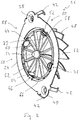
Fig. 3 - 5 ist eine gemäß den Prinzipien der vorliegenden Erfindung aufgebaute Mischerbaugruppe in Verbindung mit einem rohrartigen Abgasführungselement bzw. in eine Abgasanlage integriert dargestellt. In diesen Figuren sind Komponenten bzw. Systembereiche, welche vorangehend mit Bezug auf dieFig. 1 und2 beschriebenen Komponenten bzw. Systembereiche hinsichtlich Aufbau bzw. Funktion entsprechen, mit den gleichen Bezugszeichen unter Hinzufügen des Anhangs "a" bezeichnet. Dabei ist insbesondere darauf hinzuweisen, dass der Mischerkörper 48a der erfindungsgemäß aufgebauten Mischerbaugruppe 26a hinsichtlich seiner baulichen Ausgestaltung mit den in Umfangsrichtung aufeinanderfolgenden, schaufelartigen Strömungsablenkelementen 62a dem vorangehend mit Bezug auf dieFigur 2 beschriebenen Aufbau im Wesentlichen entspricht. Insofern kann diesbezüglich auch auf die voranstehenden Ausführungen zur Ausgestaltung des Mischerkörpers 48a verwiesen werden. - Bei dem erfindungsgemäßen Aufbau einer Mischerbaugruppe 26a schließt radial außen an den Mischerkörper 48a ein Integral, also einstückig damit ausgebildeter Trägerbereich 24a an. Dieser ersetzt das bei der vorangehend mit Bezug auf die
Fig. 1 und2 beschriebenen Ausgestaltung einer Mischerbaugruppe vorhandene und als separates Bauteil ausgebildete Trägerelement. - Der Trägerbereich 24a ist ringartig ausgebildet und umgibt die Mischerlängsachse L im Wesentlichen unterbrechungsfrei. In seinem radial Inneren, an den Mischerkörper 48a anschließenden Abschnitt stellt der Trägerbereich 24a einen Abgasführungselement-Verbindungsbereich 72a bereit. Dieser ringartig um die Mischerlängsachse L sich erstreckende Abgasführungselement-Verbindungsbereich 72a weist einen ringartigen Innen-Verbindungsbereich 74a auf, von welchem beispielsweise auch die in Umfangsrichtung aufeinanderfolgenden Strömungsablenkelemente 62a sich erstrecken können. In diesem Bereich ist also im Wesentlichen ein Übergang zwischen dem Mischerkörper 48a und dem Trägerbereich 24a bereitgestellt.
- In radialem Abstand zu dem Innen-Verbindungsbereich 74a weist der Trägerbereich 24a einen Außen-Verbindungsbereich 76a auf. Zwischen dem Innen-Verbindungsbereich 74a und dem Außen-Verbindungsbereich 76a ist ein Abgasführungselementen-Aufnahmeraum 78a gebildet, der in Richtung der Mischerlängsachse L und in Richtung zur Abströmseite 60a des Mischerkörpers 48a offen ist. In den Abgasführungselementen-Aufnahmeraum 78a kann ein axialer Endbereich 80a des rohrartigen Abgasführungselements 16a eingeführt werden, so dass der Innen-Verbindungsbereich 74a den Endbereich 80a des Abgasführungselements 16a radial innen axial übergreift und der Außen-Verbindungsbereich 76a den Endbereich 80a des Abgasführungselements 16a radial außen axial übergreift. Für eine definierte Relativpositionierung kann das Abgasführungselement 16a mit seinem Endbereich 80a so weit in den Abgasführungselementen-Aufnahmeraum 78a eingeführt werden, dass es an einem diesen in axialer Richtung begrenzenden Bodenbereich 82a anstößt.
- In dem in
Fig. 5 auch erkennbaren Zustand, in welchem das Abgasführungselement 16a mit seinem Endbereich 80a in den Abgasführungselementen-Aufnahmeraum 78a eingeführt ist, und der Trägerbereich 24a bzw. die gesamte Mischerbaugruppe 26a definiert bezüglich des Abgasführungselements 16a positioniert ist, kann eine feste Verbindung zwischen diesen beiden Baugruppen durch Bilden einer in Umfangsrichtung um die Mischerlängsachse L vorzugsweise vollständig umlaufenden Schweißnaht 84a erreicht werden. Diese stellt gleichermaßen auch einen gasdichten Anschluss des Trägerbereichs 24a an das Abgasführungselement 16a sicher. Auf diese Art und Weise wird eine inFigur 4 erkennbare Abgasführungsbaugruppe 86a erhalten, welche das rohrartige Abgasführungselement 16a und die an dessen axialen Endbereich 80a angebundene Mischerbaugruppe 26a umfasst. Die Abgasführungsbaugruppe 86a kann beispielsweise ein zu einer Katalysatoranordnung oder einer sonstigen Abgasbehandlungsbaugruppe führendes Vorrohr oder dergleichen sein. - Zur stabilen Anbindung der Abgasführungsbaugruppe 86a an einen stromaufwärtigen Systembereich, beispielsweise das rohrartige Abgasführungselement 14a, welches ein von einem weiter stromaufwärts positionierten Systembereich der Abgasanlage 10a herführendes Rohr oder ein Rohrstutzen oder dergleichen sein kann, weist der Trägerbereich 24a der Mischerbaugruppe 26a ferner einen allgemein mit 88a bezeichneten flanschartigen Kopplungsabschnitt auf. Dieser ist bezüglich des Abgasführungselementen-Verbindungsbereichs 72a in Richtung der Mischerlängsachse L von der Abströmseite 60a weg versetzt und erstreckt sich im Wesentlichen radial außerhalb des Abgasführungselementen-Verbindungsbereichs 72a bzw. ausgehend von diesem nach radial außen. Der Kopplungsabschnitt 88a weist eine in Richtung zur Abströmseite 60a orientierte Kopplungselementanlagefläche 90a auf. Diese ist bezüglich der Mischerlängsachse L bzw. in einer dazu orthogonalen Ebene angestellt und weist eine beispielsweise kegelstumpfartige Kontur auf. Die Kopplungselementanlagefläche 90a erstreckt sich somit von radial innen nach radial außen in Richtung von der Abströmseite 60a weg.
- An seiner der Kopplungselementanlagefläche 90a entgegengesetzten Axialseite weist der flanschartige Kopplungsabschnitt 88a eine Kopplungsabschnittanlagefläche 92a auf. Diese von der Abströmseite 60a somit wegorientierte Kopplungsabschnittanlagefläche 92a weist ebenfalls eine kegelstrumpfartige Formgebung auf und ist somit bezüglich der Mischerlängsachse L bzw. einer dazu orthogonalen Ebene angestellt, so dass sie sich von radial innen nach radial außen in Richtung von der Abströmseite 60a weg erstreckt. Beispielsweise kann der Anstellwinkel der Kopplungsabschnittanlagefläche 92a dem Anstellwinkel der Kopplungselementanlagefläche 90a entsprechen, so dass hier beispielsweise kegelstumpfartige Strukturen mit gleichem Kegelwinkel erhalten werden und die beiden Flächen 90a, 92a zueinander im Wesentlichen parallel sind. Grundsätzlich könnte auch eine von einer parallelen Anordnung abweichende, beispielsweise nach radial außen aufeinander zulaufende Geometrie dieser beiden Flächen bereitgestellt sein.
- In Zuordnung zu dem weiteren Abgasführungselement 14a ist ein an einem axialen Endbereich 94a des Abgasführungselements 14a beispielsweise durch eine Schweißnaht 96a fest und gasdicht angebundener flanschartiger Kopplungsabschnitt 98a vorgesehen. Dieser weist in Zuordnung zu der Kopplungsabschnittanlagefläche 92a am Kopplungsabschnitt 88a des Trägerbereichs 24a eine in Richtung zur Abströmseite 60a des Mischerkörpers 26a orientierte Kopplungsabschnittanlagefläche 100a auf. Auch diese ist bezüglich der Mischerlängsachse L bzw. einer dazu orthogonalen Ebene angestellt und weist eine der Geometrie der Kopplungsabschnittanlagefläche 92a entsprechende Geometrie, also beispielsweise auch eine kegelstumpfartige Geometrie auf. Die beiden Kopplungsabschnittanlageflächen 92a, 100a gestatten somit eine die beiden Kopplungsabschnitte 98a, 88a bezüglich einander zentrierende, flächige und somit auch einen gasdichten Anschluss herstellende Anlage der beiden Kopplungsabschnitte 88a, 98a aneinander.
- Um einen festen Zusammenhalt zu erzeugen, ist ein die beiden Kopplungsabschnitte 88a, 98a radial außen umgebendes Kopplungselement 102a vorgesehen. Dieses mit allgemein ringartiger Struktur aufgebaute Kopplungselement 102a übergreift die beiden Kopplungsabschnitte 88a, 98a an ihren voneinander abgewandt liegenden Axialseiten 104a, 106a, also an der Kopplungselementenanlagefläche 90a des Kopplungsabschnitts 88a und einer entsprechenden Kopplungselementenanlagefläche 108a des Kopplungsabschnitts 98a. Die Kopplungselementenanlagefläche 108a des Kopplungsabschnitts 98a ist bezüglich der Mischerlängsachse L bzw. einer dazu orthogonalen Ebene angestellt und zwar derart, dass sie sich von radial innen nach radial außen in Richtung zur Abströmseite 60a des Mischerkörpers 26a erstreckt. Auch hier kann beispielsweise eine kegelstumpfartige Geometrie für die Kopplungselementenanlagefläche 108a vorgesehen sein. Die beiden Kopplungselementenanlageflächen 90a, 108a bilden somit in dem in
Figur 5 erkennbaren Querschnitt eine von radial innen nach radial außen sich verjüngende Struktur, welche in einen komplementär geformten Kopplungsabschnittaufnahmeraum 110a im Kopplungselement 102a eingreifend positioniert ist. - Das Kopplungselement 102a kann beispielsweise mit zwei gelenkig miteinander verbundenen Umfangsabschnitten ausgebildet sein, die in einem aneinander angrenzenden Umfangsbereich durch ein Verspannelement, beispielsweise eine Spannschraube 112a, in Umfangsrichtung aufeinander zu verspannt werden können und dabei eine nach radial innen gerichtete Kraft auf die beiden Kopplungsabschnitte 88a, 98a ausüben. Dadurch werden die beiden Kopplungsabschnitte 88a, 98a verstärkt axial gegeneinander gepresst, und im Bereich der gegenseitigen Anlage der Kopplungsabschnittanlageflächen 92a, 100a ein gasdichter Abschluss gewährleistet.
- Bei dem erfindungsgemäßen Aufbau der Mischerbaugruppe 26a stellt diese mit dem Mischerkörper 48a einerseits den für eine effiziente Durchmischung von Abgas und weiter stromaufwärts eingedüstem Reaktionsmittel erforderliche Formation bereit, und stellt gleichermaßen mit dem Trägerbereich 24a die zum Integrieren in eine Abgasanlage aufgebaute Formation bereit, welche einerseits den Abgasführungselementen-Verbindungsbereich 72a und andererseits den flanschartigen Kopplungsabschnitt 88a umfasst. All diese Formationen bzw. Funktionsbereiche sind an ein- und derselben Baugruppe, welche wiederum als ein einziger Körper, also ein einziges Bauteil bereitgestellt ist, vorgesehen. Dieses Bauteil bzw. diese Baugruppe kann beispielsweise in einem Gussvorgang oder einem Sintervorgang aus Metallmaterial aufgebaut werden.
- Es ist abschließend darauf hinzuweisen, dass, ohne von den Prinzipien der vorliegenden Erfindung abzuweichen, in der baulichen Ausgestaltung der Mischerbaugruppe verschiedenste Variationen vorgenommen werden können. So können beispielsweise die schaufelartigen Strömungsablenkelemente mit anderer Anzahl oder anderer Geometrie bereit gestellt sein. Insbesondere die Kopplungsabschnitte könnten auch so ausgestaltet sein, dass eine Verbindung der beiden den verschiedenen Abgasführungselementen zugeordneten Kopplungsabschnitte nicht durch ein diese radial außen umgebendes und übergreifendes Kopplungselement sondern durch im Wesentlichen axial eingeführte Schraubbolzen realisiert wird. In diesem Falle ist es vorteilhaft, wenn die beiden Kopplungsabschnitte an ihren voneinander abgewandten Axialseiten mit zur Mischerlängsachse L orthogonal, also nicht angestellten Flächen aufgebaut sind.
Claims (15)
- Mischerbaugruppe, insbesondere für eine Abgasanlage einer Fahrzeugbrennkraftmaschine, umfassend einen Mischerkörper (48a) mit einer Anströmseite (58a) und einer Abströmseite (60a) und einer Mehrzahl von Strömungsablenkelementen (62a) und einen bezüglich einer Mischerlängsachse (L) radial außen an dem Mischerkörper (48a) vorgesehenen Trägerbereich (24a), wobei der Trägerbereich (24a) einen Abgasführungselementen-Verbindungsbereich (72a) zur festen Anbindung an ein vorzugsweise rohrartiges Abgasführungselement (16a) und radial außerhalb des Abgangsführungselementen-Verbindungsbereichs (72a) einen flanschartigen Kopplungsabschnitt (88a) zur Kopplung mit einem flanschartigen Kopplungsabschnitt (98a) eines weiteren Abgasführungselements (14a) aufweist.
- Mischerbaugruppe nach Anspruch 1, dadurch gekennzeichnet, dass der Abgasführungselementen-Verbindungsbereich (72a) einen ringartigen, ein Abgasführungselement (16a) an seiner Außenseite axial übergreifend zu positionierenden Außen-Verbindungsbereich (76a) oder/und einen ringartigen, ein Abgasführungselement (16a) an seiner Innenseite axial übergreifend zu positionierenden Innen-Verbindungsbereich (74a) umfasst.
- Mischerbaugruppe nach Anspruch 2, dadurch gekennzeichnet,
dass zwischen dem Außen-Verbindungsbereich (76a) und dem Innen-Verbindungsbereich (74a) ein im Wesentlichen in Richtung der Mischerlängsachse (L) in Richtung zur Abströmseite (60a) offener, ringartiger Abgasführungselementen-Aufnahmeraum (78a) gebildet ist,
oder/und
dass der Außen-Verbindungsbereich (76a) oder/und der Innen-Verbindungsbereich (74a) in Umfangsrichtung um die Mischerlängsachse (L) unterbrechungsfrei umlaufend ausgebildet ist. - Mischerbaugruppe nach einem der vorangehenden Ansprüche, dadurch gekennzeichnet,
dass der flanschartige Kopplungsabschnitt (88a) in Umfangsrichtung um die Mischerlängsachse (L) unterbrechungsfrei umlaufend ausgebildet ist, oder/und
dass der flanschartige Kopplungsabschnitt (88a) eine in Richtung Abströmseite (60a) orientierte Kopplungselementenanlagefläche (90a) aufweist. - Mischerbaugruppe nach Anspruch 4, dadurch gekennzeichnet, dass die Kopplungselementenanlagefläche (90a) von radial innen nach radial außen in Richtung von der Abströmseite (60a) weg geneigt ist, oder/und dass die Kopplungselementenanlagefläche (90a) als Kegelstumpffläche ausgebildet ist.
- Mischerbaugruppe nach einem der vorangehenden Ansprüche, dadurch gekennzeichnet, dass der flanschartige Kopplungsabschnitt (88a) eine in Richtung von der Abströmseite (60a) weg orientierte Kopplungsabschnittanlagefläche (92a) zur Anlage an einem flanschartigen Kopplungsabschnitt (98a) eines weiteren Abgasführungselements (14a) aufweist
vorzugsweise wobei die Kopplungsabschnittanlagefläche (92a) von radial innen nach radial außen in Richtung von der Abströmseite (60a) weg geneigt ist, oder/und dass die Kopplungsabschnittanlagefläche (92a) als Kegelstumpffläche ausgebildet ist. - Mischerbaugruppe nach Anspruch 4 und Anspruch 6, dadurch gekennzeichnet, dass die Kopplungselementenanlagefläche (90a) und die Kopplungsabschnittanlagefläche (92a) zueinander im Wesentlichen parallel sind.
- Mischerbaugruppe nach einem der vorangehenden Ansprüche, dadurch gekennzeichnet,
dass der flanschartigen Kopplungsabschnitt (88a) bezüglich des Abgasführungselementen-Verbindungsbereichs (72a) in Richtung von der Abströmseite (60a) weg axial versetzt ist,
oder/und
dass der Mischerkörper (48a) mit dem Trägerbereich (24a) einstückig, vorzugsweise als Gussbauteil, hergestellt ist. - Abgasführungsbaugruppe, umfassend ein vorzugsweise rohrartiges Abgasführungselement (16a) und an einem axialen Endbereich (80a) des Abgasführungselements (16a) eine Mischerbaugruppe (26a) nach einem der vorangehenden Ansprüche.
- Abgasführungsbaugruppe nach Anspruch 9, dadurch gekennzeichnet, dass die Mischerbaugruppe (26a) mit ihrem Trägerbereich (24a) am axialen Endbereich (80a) des Abgasführungselements (16a) durch Verschweißen festgelegt ist.
- Abgasanlage, insbesondere für eine Fahrzeugbrennkraftmaschine, umfassend eine Abgasführungsbaugruppe (86a) nach Anspruch 9 oder 10 und ein weiteres vorzugsweise rohrartiges Abgasführungselement (14a) mit einem flanschartigen Kopplungsabschnitt (98a).
- Abgasanlage nach Anspruch 11, dadurch gekennzeichnet, dass der flanschartige Kopplungsabschnitt (88a) der Abgasführungsbaugruppe (86a) mit dem flanschartigen Kopplungsabschnitt (98a) des weiteren Abgasführungselements (14a) durch ein diese wenigstens bereichsweise radial außen umgebendes und an ihren voneinander abgewandt orientierten Axialseiten (104a, 106a) nach radial innen übergreifendes Kopplungselement (102a) miteinander gekoppelt sind.
- Abgasanlage nach Anspruch 12, dadurch gekennzeichnet, dass der flanschartige Kopplungsabschnitt (98a) des weiteren Abgasführungselements (14a) eine von radial innen nach radial außen in Richtung auf den flanschartigen Kopplungsabschnitt (88a) der Abgasführungsbaugruppe (86a) zu geneigte, vorzugsweise kegelstumpfartige Kopplungselementenanlagefläche (108a) aufweist.
- Abgasanlage nach Anspruch 13, dadurch gekennzeichnet, dass das Kopplungselement (102a) einen die flanschartigen Kopplungsabschnitte (88a, 98a) aufnehmenden, von radial innen nach radial außen sich verjüngen Kopplungsabschnittaufnahmeraum (110a) aufweist.
- Abgasanlage nach Anspruch 12, 13 oder 14, dadurch gekennzeichnet, dass der flanschartige Kopplungsabschnitt (98a) des weiteren Abgasführungselements (14a) eine von radial innen nach radial außen in Richtung von dem flanschartigen Kopplungsabschnitt (88a) der Abgasführungsbaugruppe (86a) weg geneigte, vorzugsweise kegelstumpfartige Kopplungsabschnittanlagefläche (100a) aufweist.
Applications Claiming Priority (1)
| Application Number | Priority Date | Filing Date | Title |
|---|---|---|---|
| DE102018107768.8A DE102018107768A1 (de) | 2018-04-03 | 2018-04-03 | Mischerbaugruppe |
Publications (2)
| Publication Number | Publication Date |
|---|---|
| EP3549662A1 true EP3549662A1 (de) | 2019-10-09 |
| EP3549662B1 EP3549662B1 (de) | 2020-11-04 |
Family
ID=66001107
Family Applications (1)
| Application Number | Title | Priority Date | Filing Date |
|---|---|---|---|
| EP19166025.7A Active EP3549662B1 (de) | 2018-04-03 | 2019-03-29 | Mischerbaugruppe |
Country Status (4)
| Country | Link |
|---|---|
| US (1) | US11365668B2 (de) |
| EP (1) | EP3549662B1 (de) |
| CN (1) | CN110359988B (de) |
| DE (1) | DE102018107768A1 (de) |
Families Citing this family (1)
| Publication number | Priority date | Publication date | Assignee | Title |
|---|---|---|---|---|
| DE102021132929A1 (de) * | 2021-12-14 | 2023-06-15 | Purem GmbH | Anschlusselement für eine Abgasanlage einer Brennkraftmaschine |
Citations (3)
| Publication number | Priority date | Publication date | Assignee | Title |
|---|---|---|---|---|
| EP2474721A1 (de) * | 2011-01-11 | 2012-07-11 | Etablissements CAILLAU | Verbindungsvorrichtung zwischen Rohren und Klemmensystem mit solch einer Verbindungsvorrichtung |
| DE202012011764U1 (de) * | 2012-12-07 | 2013-03-21 | Eberspächer Catem Gmbh & Co. Kg | Mischer zur Nachbehandlung von Abgasen |
| DE102013201402A1 (de) * | 2012-02-13 | 2013-08-14 | Kabushiki Kaisha Toyota Jidoshokki | Mischvorrichtung |
Family Cites Families (18)
| Publication number | Priority date | Publication date | Assignee | Title |
|---|---|---|---|---|
| US1182954A (en) * | 1912-05-13 | 1916-05-16 | American Motors Corp | Mixing device. |
| US1279771A (en) * | 1918-02-11 | 1918-09-24 | Fred E Tallmadge | Gas-mixer. |
| US1527355A (en) * | 1922-06-21 | 1925-02-24 | Scipio S Gentile | Attachment for internal-combustion engines |
| US2703722A (en) * | 1951-06-19 | 1955-03-08 | Marman Products Company Inc | Tube coupling with frusto-conical metallic seal |
| DE10054006A1 (de) * | 2000-11-01 | 2002-05-08 | Daimler Chrysler Ag | Luftspaltisolierter Abgaskrümmer für eine Brennkraftmaschine |
| WO2006094306A2 (en) * | 2005-03-04 | 2006-09-08 | Breeze-Torca Products, Llc | Pipe clamp assembly with v-ring insert |
| US7533520B2 (en) * | 2006-04-24 | 2009-05-19 | Fleetguard, Inc. | Exhaust aftertreatment mixer with stamped muffler flange |
| US9095827B2 (en) * | 2008-04-21 | 2015-08-04 | Tenneco Automotive Operating Company Inc. | Exhaust gas flow mixer |
| US8272777B2 (en) * | 2008-04-21 | 2012-09-25 | Heinrich Gillet Gmbh (Tenneco) | Method for mixing an exhaust gas flow |
| US8418449B2 (en) * | 2008-09-25 | 2013-04-16 | Fev Gmbh | Variable exhaust gas deflector |
| EP2980382B1 (de) * | 2013-03-28 | 2018-03-21 | Yanmar Co., Ltd. | Abgasanlage |
| DE102013208184A1 (de) * | 2013-05-03 | 2014-11-06 | Eberspächer Exhaust Technology GmbH & Co. KG | Abgasanlagenkomponente |
| DE102014215083B4 (de) * | 2014-07-31 | 2023-11-02 | Purem GmbH | Mischer und Mischeinrichtung für eine Abgasanlage |
| TR201808542T4 (tr) * | 2014-08-13 | 2018-07-23 | Officine Metallurgiche G Cornaglia S P A | I.C. Motorların egzoz gazları için hareketli kanatlara sahip dinamik mikser. |
| JP6484891B2 (ja) * | 2015-09-30 | 2019-03-20 | ヤンマー株式会社 | 排気浄化装置 |
| DE102016120171A1 (de) * | 2016-10-11 | 2018-04-12 | Eberspächer Exhaust Technology GmbH & Co. KG | Mischerbaugruppe |
| US11136910B2 (en) * | 2017-06-06 | 2021-10-05 | Cummins Emission Solutions Inc. | Systems and methods for mixing exhaust gases and reductant in an aftertreatment system |
| DE102019100267A1 (de) * | 2019-01-08 | 2020-07-09 | Eberspächer Exhaust Technology GmbH & Co. KG | Mischer für eine Abgasanlage einer Brennkraftmaschine |
-
2018
- 2018-04-03 DE DE102018107768.8A patent/DE102018107768A1/de not_active Withdrawn
-
2019
- 2019-03-28 CN CN201910240183.7A patent/CN110359988B/zh active Active
- 2019-03-29 EP EP19166025.7A patent/EP3549662B1/de active Active
- 2019-04-02 US US16/372,921 patent/US11365668B2/en active Active
Patent Citations (3)
| Publication number | Priority date | Publication date | Assignee | Title |
|---|---|---|---|---|
| EP2474721A1 (de) * | 2011-01-11 | 2012-07-11 | Etablissements CAILLAU | Verbindungsvorrichtung zwischen Rohren und Klemmensystem mit solch einer Verbindungsvorrichtung |
| DE102013201402A1 (de) * | 2012-02-13 | 2013-08-14 | Kabushiki Kaisha Toyota Jidoshokki | Mischvorrichtung |
| DE202012011764U1 (de) * | 2012-12-07 | 2013-03-21 | Eberspächer Catem Gmbh & Co. Kg | Mischer zur Nachbehandlung von Abgasen |
Also Published As
| Publication number | Publication date |
|---|---|
| US11365668B2 (en) | 2022-06-21 |
| US20190301344A1 (en) | 2019-10-03 |
| CN110359988B (zh) | 2021-07-13 |
| CN110359988A (zh) | 2019-10-22 |
| EP3549662B1 (de) | 2020-11-04 |
| DE102018107768A1 (de) | 2019-10-10 |
Similar Documents
| Publication | Publication Date | Title |
|---|---|---|
| DE102011077156B4 (de) | Abgasanlage und Injektionsmodul | |
| DE102021107564B4 (de) | Fahrzeugabgasanlagenmischer mit flexibler dosiererhalterung | |
| DE102015115220B4 (de) | Mischerbaugruppe zur Bereitstellung eines kompakten Mischers | |
| EP2161423B1 (de) | Abgasanlage für Dieselfahrzeuge mit einem SCR-Katalysator | |
| EP1953359B1 (de) | Abgasanlage für eine Brennkraftmaschine | |
| EP2598730B1 (de) | Vorrichtung zur motornahen abgasbehandlung | |
| EP2980379B2 (de) | Injektionseinrichtung und zugehöriges herstellungsverfahren | |
| AT516102B1 (de) | Abgasreinigungsvorrichtung für ein Fahrzeug, insbesondere für ein Nutzfahrzeug | |
| EP1985356A2 (de) | Misch- und/oder Verdampfungseinrichtung und zugehöriges Herstellungsverfahren | |
| DE102022121578A1 (de) | Mischer, Abgasbehandlungskomponente, Abgasnachbehandlungssystem und Transportmittel | |
| WO2012131042A1 (de) | Kompakte abgasbehandlungseinheit mit mischbereich und verfahren zur vermischung eines abgases | |
| EP3406873A1 (de) | Abgasnachbehandlungssystem für einen verbrennungsmotor | |
| DE102017101749A1 (de) | Mischerelement zum Einmischen eines Fluids in ein Abgas eines Verbrennungsmotors sowie Abgasstrang für einen Verbrennungsmotor | |
| EP3412879B1 (de) | Abgasnachbehandlungsvorrichtung einer brennkraftmaschine eines kraftfahrzeugs | |
| EP3549663B1 (de) | Abgasanlage und mischerbaugruppe für eine abgasanlage | |
| DE102016120171A1 (de) | Mischerbaugruppe | |
| EP3726017B1 (de) | Mischer | |
| EP3549662B1 (de) | Mischerbaugruppe | |
| DE102019104772A1 (de) | Abgasanlage | |
| DE102020124088A1 (de) | Flexible verbindung für mischerbaugruppe | |
| EP4390069B1 (de) | Abgasbehandlungsanordnung | |
| EP3680463A1 (de) | Mischer für eine abgasanlage einer brennkraftmaschine | |
| EP3808950A1 (de) | Mischeranordnung | |
| EP3308847B1 (de) | Mischerbaugruppe | |
| EP4063626B1 (de) | Abgas/reaktionsmittel-mischbaugruppe |
Legal Events
| Date | Code | Title | Description |
|---|---|---|---|
| PUAI | Public reference made under article 153(3) epc to a published international application that has entered the european phase |
Free format text: ORIGINAL CODE: 0009012 |
|
| STAA | Information on the status of an ep patent application or granted ep patent |
Free format text: STATUS: THE APPLICATION HAS BEEN PUBLISHED |
|
| AK | Designated contracting states |
Kind code of ref document: A1 Designated state(s): AL AT BE BG CH CY CZ DE DK EE ES FI FR GB GR HR HU IE IS IT LI LT LU LV MC MK MT NL NO PL PT RO RS SE SI SK SM TR |
|
| AX | Request for extension of the european patent |
Extension state: BA ME |
|
| STAA | Information on the status of an ep patent application or granted ep patent |
Free format text: STATUS: REQUEST FOR EXAMINATION WAS MADE |
|
| 17P | Request for examination filed |
Effective date: 20200403 |
|
| RBV | Designated contracting states (corrected) |
Designated state(s): AL AT BE BG CH CY CZ DE DK EE ES FI FR GB GR HR HU IE IS IT LI LT LU LV MC MK MT NL NO PL PT RO RS SE SI SK SM TR |
|
| GRAP | Despatch of communication of intention to grant a patent |
Free format text: ORIGINAL CODE: EPIDOSNIGR1 |
|
| STAA | Information on the status of an ep patent application or granted ep patent |
Free format text: STATUS: GRANT OF PATENT IS INTENDED |
|
| INTG | Intention to grant announced |
Effective date: 20200707 |
|
| GRAS | Grant fee paid |
Free format text: ORIGINAL CODE: EPIDOSNIGR3 |
|
| GRAA | (expected) grant |
Free format text: ORIGINAL CODE: 0009210 |
|
| STAA | Information on the status of an ep patent application or granted ep patent |
Free format text: STATUS: THE PATENT HAS BEEN GRANTED |
|
| AK | Designated contracting states |
Kind code of ref document: B1 Designated state(s): AL AT BE BG CH CY CZ DE DK EE ES FI FR GB GR HR HU IE IS IT LI LT LU LV MC MK MT NL NO PL PT RO RS SE SI SK SM TR |
|
| REG | Reference to a national code |
Ref country code: GB Ref legal event code: FG4D Free format text: NOT ENGLISH |
|
| REG | Reference to a national code |
Ref country code: CH Ref legal event code: EP |
|
| REG | Reference to a national code |
Ref country code: AT Ref legal event code: REF Ref document number: 1330084 Country of ref document: AT Kind code of ref document: T Effective date: 20201115 |
|
| REG | Reference to a national code |
Ref country code: IE Ref legal event code: FG4D Free format text: LANGUAGE OF EP DOCUMENT: GERMAN |
|
| REG | Reference to a national code |
Ref country code: DE Ref legal event code: R096 Ref document number: 502019000358 Country of ref document: DE |
|
| REG | Reference to a national code |
Ref country code: SE Ref legal event code: TRGR |
|
| REG | Reference to a national code |
Ref country code: NL Ref legal event code: MP Effective date: 20201104 |
|
| PG25 | Lapsed in a contracting state [announced via postgrant information from national office to epo] |
Ref country code: GR Free format text: LAPSE BECAUSE OF FAILURE TO SUBMIT A TRANSLATION OF THE DESCRIPTION OR TO PAY THE FEE WITHIN THE PRESCRIBED TIME-LIMIT Effective date: 20210205 Ref country code: NO Free format text: LAPSE BECAUSE OF FAILURE TO SUBMIT A TRANSLATION OF THE DESCRIPTION OR TO PAY THE FEE WITHIN THE PRESCRIBED TIME-LIMIT Effective date: 20210204 Ref country code: FI Free format text: LAPSE BECAUSE OF FAILURE TO SUBMIT A TRANSLATION OF THE DESCRIPTION OR TO PAY THE FEE WITHIN THE PRESCRIBED TIME-LIMIT Effective date: 20201104 Ref country code: RS Free format text: LAPSE BECAUSE OF FAILURE TO SUBMIT A TRANSLATION OF THE DESCRIPTION OR TO PAY THE FEE WITHIN THE PRESCRIBED TIME-LIMIT Effective date: 20201104 Ref country code: PT Free format text: LAPSE BECAUSE OF FAILURE TO SUBMIT A TRANSLATION OF THE DESCRIPTION OR TO PAY THE FEE WITHIN THE PRESCRIBED TIME-LIMIT Effective date: 20210304 |
|
| PG25 | Lapsed in a contracting state [announced via postgrant information from national office to epo] |
Ref country code: ES Free format text: LAPSE BECAUSE OF FAILURE TO SUBMIT A TRANSLATION OF THE DESCRIPTION OR TO PAY THE FEE WITHIN THE PRESCRIBED TIME-LIMIT Effective date: 20201104 Ref country code: BG Free format text: LAPSE BECAUSE OF FAILURE TO SUBMIT A TRANSLATION OF THE DESCRIPTION OR TO PAY THE FEE WITHIN THE PRESCRIBED TIME-LIMIT Effective date: 20210204 Ref country code: PL Free format text: LAPSE BECAUSE OF FAILURE TO SUBMIT A TRANSLATION OF THE DESCRIPTION OR TO PAY THE FEE WITHIN THE PRESCRIBED TIME-LIMIT Effective date: 20201104 Ref country code: LV Free format text: LAPSE BECAUSE OF FAILURE TO SUBMIT A TRANSLATION OF THE DESCRIPTION OR TO PAY THE FEE WITHIN THE PRESCRIBED TIME-LIMIT Effective date: 20201104 Ref country code: IS Free format text: LAPSE BECAUSE OF FAILURE TO SUBMIT A TRANSLATION OF THE DESCRIPTION OR TO PAY THE FEE WITHIN THE PRESCRIBED TIME-LIMIT Effective date: 20210304 |
|
| REG | Reference to a national code |
Ref country code: LT Ref legal event code: MG9D |
|
| PG25 | Lapsed in a contracting state [announced via postgrant information from national office to epo] |
Ref country code: HR Free format text: LAPSE BECAUSE OF FAILURE TO SUBMIT A TRANSLATION OF THE DESCRIPTION OR TO PAY THE FEE WITHIN THE PRESCRIBED TIME-LIMIT Effective date: 20201104 |
|
| REG | Reference to a national code |
Ref country code: DE Ref legal event code: R082 Ref document number: 502019000358 Country of ref document: DE Representative=s name: RUTTENSPERGER LACHNIT TROSSIN GOMOLL, PATENT- , DE Ref country code: DE Ref legal event code: R081 Ref document number: 502019000358 Country of ref document: DE Owner name: PUREM GMBH, DE Free format text: FORMER OWNER: EBERSPAECHER EXHAUST TECHNOLOGY GMBH & CO. KG, 66539 NEUNKIRCHEN, DE |
|
| PG25 | Lapsed in a contracting state [announced via postgrant information from national office to epo] |
Ref country code: LT Free format text: LAPSE BECAUSE OF FAILURE TO SUBMIT A TRANSLATION OF THE DESCRIPTION OR TO PAY THE FEE WITHIN THE PRESCRIBED TIME-LIMIT Effective date: 20201104 Ref country code: RO Free format text: LAPSE BECAUSE OF FAILURE TO SUBMIT A TRANSLATION OF THE DESCRIPTION OR TO PAY THE FEE WITHIN THE PRESCRIBED TIME-LIMIT Effective date: 20201104 Ref country code: SK Free format text: LAPSE BECAUSE OF FAILURE TO SUBMIT A TRANSLATION OF THE DESCRIPTION OR TO PAY THE FEE WITHIN THE PRESCRIBED TIME-LIMIT Effective date: 20201104 Ref country code: SM Free format text: LAPSE BECAUSE OF FAILURE TO SUBMIT A TRANSLATION OF THE DESCRIPTION OR TO PAY THE FEE WITHIN THE PRESCRIBED TIME-LIMIT Effective date: 20201104 Ref country code: EE Free format text: LAPSE BECAUSE OF FAILURE TO SUBMIT A TRANSLATION OF THE DESCRIPTION OR TO PAY THE FEE WITHIN THE PRESCRIBED TIME-LIMIT Effective date: 20201104 Ref country code: CZ Free format text: LAPSE BECAUSE OF FAILURE TO SUBMIT A TRANSLATION OF THE DESCRIPTION OR TO PAY THE FEE WITHIN THE PRESCRIBED TIME-LIMIT Effective date: 20201104 |
|
| REG | Reference to a national code |
Ref country code: DE Ref legal event code: R097 Ref document number: 502019000358 Country of ref document: DE |
|
| PG25 | Lapsed in a contracting state [announced via postgrant information from national office to epo] |
Ref country code: DK Free format text: LAPSE BECAUSE OF FAILURE TO SUBMIT A TRANSLATION OF THE DESCRIPTION OR TO PAY THE FEE WITHIN THE PRESCRIBED TIME-LIMIT Effective date: 20201104 |
|
| PLBE | No opposition filed within time limit |
Free format text: ORIGINAL CODE: 0009261 |
|
| STAA | Information on the status of an ep patent application or granted ep patent |
Free format text: STATUS: NO OPPOSITION FILED WITHIN TIME LIMIT |
|
| REG | Reference to a national code |
Ref country code: GB Ref legal event code: 732E Free format text: REGISTERED BETWEEN 20210902 AND 20210908 |
|
| 26N | No opposition filed |
Effective date: 20210805 |
|
| PG25 | Lapsed in a contracting state [announced via postgrant information from national office to epo] |
Ref country code: MC Free format text: LAPSE BECAUSE OF FAILURE TO SUBMIT A TRANSLATION OF THE DESCRIPTION OR TO PAY THE FEE WITHIN THE PRESCRIBED TIME-LIMIT Effective date: 20201104 Ref country code: IT Free format text: LAPSE BECAUSE OF FAILURE TO SUBMIT A TRANSLATION OF THE DESCRIPTION OR TO PAY THE FEE WITHIN THE PRESCRIBED TIME-LIMIT Effective date: 20201104 Ref country code: NL Free format text: LAPSE BECAUSE OF FAILURE TO SUBMIT A TRANSLATION OF THE DESCRIPTION OR TO PAY THE FEE WITHIN THE PRESCRIBED TIME-LIMIT Effective date: 20201104 Ref country code: AL Free format text: LAPSE BECAUSE OF FAILURE TO SUBMIT A TRANSLATION OF THE DESCRIPTION OR TO PAY THE FEE WITHIN THE PRESCRIBED TIME-LIMIT Effective date: 20201104 |
|
| REG | Reference to a national code |
Ref country code: DE Ref legal event code: R079 Ref document number: 502019000358 Country of ref document: DE Free format text: PREVIOUS MAIN CLASS: B01F0005060000 Ipc: B01F0025400000 |
|
| PG25 | Lapsed in a contracting state [announced via postgrant information from national office to epo] |
Ref country code: SI Free format text: LAPSE BECAUSE OF FAILURE TO SUBMIT A TRANSLATION OF THE DESCRIPTION OR TO PAY THE FEE WITHIN THE PRESCRIBED TIME-LIMIT Effective date: 20201104 |
|
| REG | Reference to a national code |
Ref country code: BE Ref legal event code: MM Effective date: 20210331 |
|
| PG25 | Lapsed in a contracting state [announced via postgrant information from national office to epo] |
Ref country code: LU Free format text: LAPSE BECAUSE OF NON-PAYMENT OF DUE FEES Effective date: 20210329 Ref country code: IE Free format text: LAPSE BECAUSE OF NON-PAYMENT OF DUE FEES Effective date: 20210329 |
|
| PG25 | Lapsed in a contracting state [announced via postgrant information from national office to epo] |
Ref country code: IS Free format text: LAPSE BECAUSE OF FAILURE TO SUBMIT A TRANSLATION OF THE DESCRIPTION OR TO PAY THE FEE WITHIN THE PRESCRIBED TIME-LIMIT Effective date: 20210304 |
|
| PG25 | Lapsed in a contracting state [announced via postgrant information from national office to epo] |
Ref country code: BE Free format text: LAPSE BECAUSE OF NON-PAYMENT OF DUE FEES Effective date: 20210331 |
|
| REG | Reference to a national code |
Ref country code: CH Ref legal event code: PL |
|
| PG25 | Lapsed in a contracting state [announced via postgrant information from national office to epo] |
Ref country code: LI Free format text: LAPSE BECAUSE OF NON-PAYMENT OF DUE FEES Effective date: 20220331 Ref country code: CH Free format text: LAPSE BECAUSE OF NON-PAYMENT OF DUE FEES Effective date: 20220331 |
|
| PGFP | Annual fee paid to national office [announced via postgrant information from national office to epo] |
Ref country code: SE Payment date: 20230315 Year of fee payment: 5 |
|
| PG25 | Lapsed in a contracting state [announced via postgrant information from national office to epo] |
Ref country code: CY Free format text: LAPSE BECAUSE OF FAILURE TO SUBMIT A TRANSLATION OF THE DESCRIPTION OR TO PAY THE FEE WITHIN THE PRESCRIBED TIME-LIMIT Effective date: 20201104 |
|
| PG25 | Lapsed in a contracting state [announced via postgrant information from national office to epo] |
Ref country code: HU Free format text: LAPSE BECAUSE OF FAILURE TO SUBMIT A TRANSLATION OF THE DESCRIPTION OR TO PAY THE FEE WITHIN THE PRESCRIBED TIME-LIMIT; INVALID AB INITIO Effective date: 20190329 |
|
| PG25 | Lapsed in a contracting state [announced via postgrant information from national office to epo] |
Ref country code: MK Free format text: LAPSE BECAUSE OF FAILURE TO SUBMIT A TRANSLATION OF THE DESCRIPTION OR TO PAY THE FEE WITHIN THE PRESCRIBED TIME-LIMIT Effective date: 20201104 |
|
| PG25 | Lapsed in a contracting state [announced via postgrant information from national office to epo] |
Ref country code: MT Free format text: LAPSE BECAUSE OF FAILURE TO SUBMIT A TRANSLATION OF THE DESCRIPTION OR TO PAY THE FEE WITHIN THE PRESCRIBED TIME-LIMIT Effective date: 20201104 |
|
| REG | Reference to a national code |
Ref country code: SE Ref legal event code: EUG |
|
| REG | Reference to a national code |
Ref country code: AT Ref legal event code: MM01 Ref document number: 1330084 Country of ref document: AT Kind code of ref document: T Effective date: 20240329 |
|
| PG25 | Lapsed in a contracting state [announced via postgrant information from national office to epo] |
Ref country code: AT Free format text: LAPSE BECAUSE OF NON-PAYMENT OF DUE FEES Effective date: 20240329 |
|
| PG25 | Lapsed in a contracting state [announced via postgrant information from national office to epo] |
Ref country code: SE Free format text: LAPSE BECAUSE OF NON-PAYMENT OF DUE FEES Effective date: 20240330 |
|
| PG25 | Lapsed in a contracting state [announced via postgrant information from national office to epo] |
Ref country code: TR Free format text: LAPSE BECAUSE OF FAILURE TO SUBMIT A TRANSLATION OF THE DESCRIPTION OR TO PAY THE FEE WITHIN THE PRESCRIBED TIME-LIMIT Effective date: 20201104 |
|
| PGFP | Annual fee paid to national office [announced via postgrant information from national office to epo] |
Ref country code: GB Payment date: 20260317 Year of fee payment: 8 |
|
| PGFP | Annual fee paid to national office [announced via postgrant information from national office to epo] |
Ref country code: DE Payment date: 20260320 Year of fee payment: 8 |
|
| PGFP | Annual fee paid to national office [announced via postgrant information from national office to epo] |
Ref country code: AT Payment date: 20260410 Year of fee payment: 5 |
|
| PGFP | Annual fee paid to national office [announced via postgrant information from national office to epo] |
Ref country code: FR Payment date: 20260325 Year of fee payment: 8 |