EP3549653A1 - Composite filter element assembly and water purification system - Google Patents
Composite filter element assembly and water purification system Download PDFInfo
- Publication number
- EP3549653A1 EP3549653A1 EP18796819.3A EP18796819A EP3549653A1 EP 3549653 A1 EP3549653 A1 EP 3549653A1 EP 18796819 A EP18796819 A EP 18796819A EP 3549653 A1 EP3549653 A1 EP 3549653A1
- Authority
- EP
- European Patent Office
- Prior art keywords
- filter
- housing
- posed
- water outlet
- membrane filter
- Prior art date
- Legal status (The legal status is an assumption and is not a legal conclusion. Google has not performed a legal analysis and makes no representation as to the accuracy of the status listed.)
- Granted
Links
Images







Classifications
-
- C—CHEMISTRY; METALLURGY
- C02—TREATMENT OF WATER, WASTE WATER, SEWAGE, OR SLUDGE
- C02F—TREATMENT OF WATER, WASTE WATER, SEWAGE, OR SLUDGE
- C02F1/00—Treatment of water, waste water, or sewage
- C02F1/001—Processes for the treatment of water whereby the filtration technique is of importance
-
- B—PERFORMING OPERATIONS; TRANSPORTING
- B01—PHYSICAL OR CHEMICAL PROCESSES OR APPARATUS IN GENERAL
- B01D—SEPARATION
- B01D29/00—Filters with filtering elements stationary during filtration, e.g. pressure or suction filters, not covered by groups B01D24/00 - B01D27/00; Filtering elements therefor
- B01D29/11—Filters with filtering elements stationary during filtration, e.g. pressure or suction filters, not covered by groups B01D24/00 - B01D27/00; Filtering elements therefor with bag, cage, hose, tube, sleeve or like filtering elements
- B01D29/13—Supported filter elements
- B01D29/15—Supported filter elements arranged for inward flow filtration
-
- B—PERFORMING OPERATIONS; TRANSPORTING
- B01—PHYSICAL OR CHEMICAL PROCESSES OR APPARATUS IN GENERAL
- B01D—SEPARATION
- B01D29/00—Filters with filtering elements stationary during filtration, e.g. pressure or suction filters, not covered by groups B01D24/00 - B01D27/00; Filtering elements therefor
- B01D29/11—Filters with filtering elements stationary during filtration, e.g. pressure or suction filters, not covered by groups B01D24/00 - B01D27/00; Filtering elements therefor with bag, cage, hose, tube, sleeve or like filtering elements
- B01D29/31—Self-supporting filtering elements
- B01D29/33—Self-supporting filtering elements arranged for inward flow filtration
-
- B—PERFORMING OPERATIONS; TRANSPORTING
- B01—PHYSICAL OR CHEMICAL PROCESSES OR APPARATUS IN GENERAL
- B01D—SEPARATION
- B01D29/00—Filters with filtering elements stationary during filtration, e.g. pressure or suction filters, not covered by groups B01D24/00 - B01D27/00; Filtering elements therefor
- B01D29/50—Filters with filtering elements stationary during filtration, e.g. pressure or suction filters, not covered by groups B01D24/00 - B01D27/00; Filtering elements therefor with multiple filtering elements, characterised by their mutual disposition
- B01D29/56—Filters with filtering elements stationary during filtration, e.g. pressure or suction filters, not covered by groups B01D24/00 - B01D27/00; Filtering elements therefor with multiple filtering elements, characterised by their mutual disposition in series connection
- B01D29/58—Filters with filtering elements stationary during filtration, e.g. pressure or suction filters, not covered by groups B01D24/00 - B01D27/00; Filtering elements therefor with multiple filtering elements, characterised by their mutual disposition in series connection arranged concentrically or coaxially
-
- B—PERFORMING OPERATIONS; TRANSPORTING
- B01—PHYSICAL OR CHEMICAL PROCESSES OR APPARATUS IN GENERAL
- B01D—SEPARATION
- B01D63/00—Apparatus in general for separation processes using semi-permeable membranes
- B01D63/10—Spiral-wound membrane modules
- B01D63/107—Specific properties of the central tube or the permeate channel
-
- C—CHEMISTRY; METALLURGY
- C02—TREATMENT OF WATER, WASTE WATER, SEWAGE, OR SLUDGE
- C02F—TREATMENT OF WATER, WASTE WATER, SEWAGE, OR SLUDGE
- C02F1/00—Treatment of water, waste water, or sewage
- C02F1/44—Treatment of water, waste water, or sewage by dialysis, osmosis or reverse osmosis
- C02F1/444—Treatment of water, waste water, or sewage by dialysis, osmosis or reverse osmosis by ultrafiltration or microfiltration
-
- B—PERFORMING OPERATIONS; TRANSPORTING
- B01—PHYSICAL OR CHEMICAL PROCESSES OR APPARATUS IN GENERAL
- B01D—SEPARATION
- B01D2201/00—Details relating to filtering apparatus
- B01D2201/30—Filter housing constructions
- B01D2201/301—Details of removable closures, lids, caps, filter heads
- B01D2201/302—Details of removable closures, lids, caps, filter heads having inlet or outlet ports
-
- B—PERFORMING OPERATIONS; TRANSPORTING
- B01—PHYSICAL OR CHEMICAL PROCESSES OR APPARATUS IN GENERAL
- B01D—SEPARATION
- B01D2313/00—Details relating to membrane modules or apparatus
- B01D2313/04—Specific sealing means
- B01D2313/041—Gaskets or O-rings
-
- B—PERFORMING OPERATIONS; TRANSPORTING
- B01—PHYSICAL OR CHEMICAL PROCESSES OR APPARATUS IN GENERAL
- B01D—SEPARATION
- B01D2313/00—Details relating to membrane modules or apparatus
- B01D2313/20—Specific housing
- B01D2313/205—Specific housing characterised by the shape
-
- B—PERFORMING OPERATIONS; TRANSPORTING
- B01—PHYSICAL OR CHEMICAL PROCESSES OR APPARATUS IN GENERAL
- B01D—SEPARATION
- B01D61/00—Processes of separation using semi-permeable membranes, e.g. dialysis, osmosis or ultrafiltration; Apparatus, accessories or auxiliary operations specially adapted therefor
- B01D61/14—Ultrafiltration; Microfiltration
- B01D61/145—Ultrafiltration
-
- B—PERFORMING OPERATIONS; TRANSPORTING
- B01—PHYSICAL OR CHEMICAL PROCESSES OR APPARATUS IN GENERAL
- B01D—SEPARATION
- B01D61/00—Processes of separation using semi-permeable membranes, e.g. dialysis, osmosis or ultrafiltration; Apparatus, accessories or auxiliary operations specially adapted therefor
- B01D61/14—Ultrafiltration; Microfiltration
- B01D61/147—Microfiltration
-
- C—CHEMISTRY; METALLURGY
- C02—TREATMENT OF WATER, WASTE WATER, SEWAGE, OR SLUDGE
- C02F—TREATMENT OF WATER, WASTE WATER, SEWAGE, OR SLUDGE
- C02F1/00—Treatment of water, waste water, or sewage
- C02F1/28—Treatment of water, waste water, or sewage by sorption
- C02F1/283—Treatment of water, waste water, or sewage by sorption using coal, charred products, or inorganic mixtures containing them
-
- C—CHEMISTRY; METALLURGY
- C02—TREATMENT OF WATER, WASTE WATER, SEWAGE, OR SLUDGE
- C02F—TREATMENT OF WATER, WASTE WATER, SEWAGE, OR SLUDGE
- C02F1/00—Treatment of water, waste water, or sewage
- C02F1/44—Treatment of water, waste water, or sewage by dialysis, osmosis or reverse osmosis
-
- C—CHEMISTRY; METALLURGY
- C02—TREATMENT OF WATER, WASTE WATER, SEWAGE, OR SLUDGE
- C02F—TREATMENT OF WATER, WASTE WATER, SEWAGE, OR SLUDGE
- C02F2201/00—Apparatus for treatment of water, waste water or sewage
- C02F2201/002—Construction details of the apparatus
- C02F2201/003—Coaxial constructions, e.g. a cartridge located coaxially within another
-
- C—CHEMISTRY; METALLURGY
- C02—TREATMENT OF WATER, WASTE WATER, SEWAGE, OR SLUDGE
- C02F—TREATMENT OF WATER, WASTE WATER, SEWAGE, OR SLUDGE
- C02F2201/00—Apparatus for treatment of water, waste water or sewage
- C02F2201/002—Construction details of the apparatus
- C02F2201/004—Seals, connections
-
- C—CHEMISTRY; METALLURGY
- C02—TREATMENT OF WATER, WASTE WATER, SEWAGE, OR SLUDGE
- C02F—TREATMENT OF WATER, WASTE WATER, SEWAGE, OR SLUDGE
- C02F2201/00—Apparatus for treatment of water, waste water or sewage
- C02F2201/002—Construction details of the apparatus
- C02F2201/006—Cartridges
Definitions
- the present disclosure relates to the technology field of water purifier, and more particularly to a composite filter assembly and a water purifier.
- a water purifier commonly filters water by multiple filters (normally 4 to 5 filters) connected with each other in series.
- the filter assembly has a larger size.
- a kind of composite filter assembly has been provided in prior art, instead of connecting the filters together in series, the filters of the composite filter assembly are coupled together by sleeving one filter by another, so as to reduce the size of the filter assembly, and miniaturize the water purifier.
- a booster pump is needed to be defined in the flow channel to adjust the pressures to be suitable for each filter.
- a connector is also needed to be defined to filter housing.
- two connectors of the water purifier which are configured to connect with the booster pump, are separately located at the filter housing up and down.
- the present disclosure is to provide a composite filter assembly, which aims to solve the problem of that the design of the connector for connecting the water purifier and the booster pump is unreasonable, and the process of assembly is complicated.
- the present disclosure provides a composite filter assembly
- the composite filter assembly defines a housing, and a composite filter defined in the housing
- the housing defines a raw water inlet, an initial filtered water outlet, a pressurized water inlet, a pure water outlet, and a waste water outlet
- the composite filter includes a pre-posed filter, a membrane filter, and a post-posed filter
- the pre-posed filter and the membrane filter are defined in a manner from outside to inside, and spaced from each other
- the post-posed filter is connected with the membrane filter and located at a downstream position of the membrane filter
- the initial filtered water outlet is communicated with an outlet end of the pre-posed filter
- the pressurized water inlet is communicated with an inlet end of the membrane filter
- the outlet end of the pre-posed filter is adjacent to the inlet end of the membrane filter
- the initial filtered water outlet is an annular opening which surrounds the pressurized water inlet.
- the post-posed filter is located upon the pre-posed filter and the membrane filter; and the initial filtered water outlet and the pressurized water inlet are both defined at a lower end surface of the housing.
- the pressurized water inlet is circular-shaped, and located at a center position of the lower end surface of the housing, the initial filtered water outlet and the pressurized water inlet are concentric.
- a radius of the pressurized water inlet is 10mm to 20mm
- a radius of a circle defined by the outer peripheral edge of the initial filtered water outlet is 25mm to 35mm.
- the housing includes an outer housing, and an inner housing received in the outer housing, the pre-posed filter is defined between the inner surface of the outer housing and the outer surface of the inner housing, the membrane filter is received in the inner housing, the post-posed filter is defined at an up end of the inner housing; a lower end surface of the outer housing defines a first opening, the periphery of the first opening extends downwards to form a first annular rib; a lower end surface of the inner housing defines a second opening, a projection of the second opening along an up-down direction is located in the first opening, the periphery of the second opening extends downwards to form a second annular rib, the second annular rib extends into the first annular rib; and an inner circumference surface of the first annular rib and an outer circumferential surface of the second annular rib cooperatively form the initial filtered water outlet, the inner circumference surface of the second annular rib defines the pressurized water inlet.
- an outer circumferential surface of the first annular rib and the outer circumferential surface of the second annular rib both define a sealing structure, the sealing structure is configured as an adaptor which is tightly connected to a booster pump of the water purification system.
- the sealing structures comprise one sealing annular groove defined at the outer circumferential surface of the first annular rib and one sealing element defined in the sealing annular groove, and another sealing annular groove located at the outer circumferential surface of the second annular rib and another sealing element defined in the another sealing annular groove.
- a connector configured to connect with an external structure is defined at a top end of the outer housing, a raw water connector, a pure water connector, and a waste water connector are all defined on the connector in a parallel manner, the raw water connector communicates with the raw water inlet, the pure water connector communicates with the pure water outlet, the waste water connector communicates with the waste water outlet.
- the membrane filter includes a central collecting pipe, and a membrane filter body coiled around the central collecting pipe, the pressurized water inlet is communicated with an inlet end of the membrane filter body, a wall of the central collecting pipe defines a plurality of communicating ports which communicate with an outlet end of the membrane filter body, a top end of the central collecting pipe is communicated with an inlet end of the post-posed filter.
- the composite filter assembly further includes a hollowed connecting housing, at least a portion of the connecting housing is defined in a top end of the inner housing, and the top end of the central collecting pipe is communicated with an inner cavity of the connecting housing; and an outer surface of the connecting housing and an inner surface of the inner housing cooperatively define a waste water flow channel for leading waste water from the membrane filter body to the waste water outlet; the post-posed filter is located in the connecting housing, the post-posed filter and an inner surface of the connecting housing cooperatively define a flow channel, an inner cavity of the post-posed filter defines a pure water flow channel for leading pure water to the pure water outlet.
- the present disclosure also provides a water purification system, which includes a booster pump and a composite filter assembly, the composite filter assembly defines a housing, and a composite filter defined in the housing, the housing includes a raw water inlet, an initial filtered water outlet, a pressurized water inlet, a pure water outlet, and a waste water outlet, the composite filter includes a pre-posed filter, a membrane filter, and a post-posed filter,the pre-posed filter and the membrane filter are defined in a manner from outside to inside, and spaced from each other, the post-posed filter is connected with the membrane filter and located at a downstream position of the membrane filter;
- the initial filtered water outlet is communicated with an outlet end of the pre-posed filter, the pressurized water inlet is communicated with an inlet end of the membrane filter; the outlet end of the pre-posed filter is adjacent to the inlet end of the membrane filter, the initial filtered water outlet is an annular opening which surrounds the pressurized water inlet; and one end of the booster pump is connected with the initial filtered water outlet, the other end of the booster pump is connected with the pressurized water inlet.
- the present disclosure also provides a composite filter assembly, applied to a water purification system, wherein, the composite filter assembly defines a housing, and a composite filter defined in the housing, the housing includes a raw water inlet, an initial filtered water outlet, a pressurized water inlet, a water storage port, a pure water outlet, and a waste water outlet, the composite filter includes a pre-posed filter, a membrane filter, and a post-posed filter,the pre-posed filter and the membrane filter are defined in a manner from outside to inside, and spaced from each other, the post-posed filter is connected with the membrane filter and located at a downstream position of the membrane filter; the initial filtered water outlet is communicated with an outlet end of the pre-posed filter, the pressurized water inlet is communicated with an inlet end of the membrane filter, the water storage port is communicated with an outlet end of the membrane filter and inlet end of the post-posed filter; and the outlet end of the pre-posed filter is adjacent to the inlet end of the membrane filter, the initial filtered water
- the post-posed filter is located upon the pre-posed filter and the membrane filter; and the initial filtered water outlet and the pressurized water inlet are both defined at a lower end surface of the housing.
- the pressurized water inlet is circular-shaped, and located at a center position of the lower end surface of the housing, the initial filtered water outlet and the pressurized water inlet are concentric.
- a radius of the pressurized water inlet is 10mm to 20mm
- a radius of a circle defined by the outer peripheral edge of the initial filtered water outlet is 25mm to 35mm.
- the housing includes an outer housing, and an inner housing received in the outer housing, the pre-posed filter is defined between the inner surface of the outer housing and the outer surface of the inner housing, the membrane filter is received in the inner housing, the post-posed filter is defined at an up end of the inner housing; a lower end surface of the outer housing defines a first opening, the periphery of the first opening extends downwards to form a first annular rib; a lower end surface of the inner housing defines a second opening, a projection of the second opening along an up-down direction is located in the first opening, the periphery of the second opening extends downwards to form a second annular rib, the second annular rib extends into the first annular rib; and an inner circumference surface of the first annular rib and an outer circumferential surface of the second annular rib cooperatively form the initial filtered water outlet, the inner circumference surface of the second annular rib defines the pressurized water inlet.
- an outer circumferential surface of the first annular rib and the outer circumferential surface of the second annular rib both define a sealing structure, the sealing structure is configured as an adaptor which is tightly connected to a booster pump of the water purification system.
- the sealing structures include one sealing annular groove defined at the outer circumferential surface of the first annular rib and one sealing element defined in the sealing annular groove, and another sealing annular groove located at the outer circumferential surface of the second annular rib and another sealing element defined in the another sealing annular groove.
- a connector configured to connect with an external structure is defined at a top end of the outer housing, a raw water connector, a water storage connector, a pure water connector, and a waste water connector are all defined on the connector in a parallel manner, the raw water connector communicates with the raw water inlet, the water storage connector communicates with the water storage port, the pure water connector communicates with the pure water outlet, the waste water connector communicates with the waste water outlet.
- the membrane filter includes a central collecting pipe, and a membrane filter body coiled around the central collecting pipe, the pressurized water inlet is communicated with an inlet end of the membrane filter body, a wall of the central collecting pipe defines a plurality of communicating ports which communicate with an outlet end of the membrane filter body, a top end of the central collecting pipe is communicated with and the water storage port and the inlet end of the post-posed filter.
- the composite filter assembly further includes a hollowed connecting housing, at least a portion of the connecting housing is defined in a top end of the inner housing, and the top end of the central collecting pipe is communicated with an inner cavity of the connecting housing; and an outer surface of the connecting housing and an inner surface of the inner housing cooperatively define a waste water flow channel for leading waste water from the membrane filter body to the waste water outlet;
- the post-posed filter is located in the connecting housing, the post-posed filter and an inner surface of the connecting housing cooperatively define a water storage flow channel for leading water from a top end of the central collecting pipe to the water storage port, an inner cavity of the post-posed filter defines a pure water flow channel for leading pure water to the pure water outlet.
- the pre-posed filter, the membrane filter, and the post-posed filter are integrated into a composite filter, as such the complete appliance is miniaturized, the number of the connectors and the risk of leakage are reduced.
- the initial filtered water outlet connected with the booster pump is configured to surround the pressurized water inlet, therefore the booster pump can be directly connected with the initial filtered water outlet and the pressurized water inlet after passing through a connector, as such there is no need to introduce a connecting pipe, etc.
- the mounting of the complete appliance is simplified, the mounting efficiency of the composite filter assembly and the water purifier is improved.
- the descriptions, such as the "first”, the “second” in the present disclosure, can only be used for describing the aim of description, and cannot be understood as indicating or suggestting relative importance or impliedly indicating the number of the indicated technical character. Therefore, the character indicated by the "first”, the “second” can express or impliedly include at least one character.
- the technical proposal of each exemplary embodiment can be combined with each other, however the technical proposal must base on that the ordinary skill in that art can realize the technical proposal, when the combination of the technical proposals occurs contradiction or cannot realize, it should consider that the combination of the technical proposals does not existed, and is not contained in the protection scope required by the present disclosure.
- the present disclosure provides a composite filter assembly, which is applied to a water purification system.
- the composite filter assembly includes a housing 1, and a composite filter defined in the housing 1, the housing 1 defines a raw water inlet (not shown), an initial filtered water outlet 111b, a pressurized water inlet 122, a pure water outlet (not shown), and a waste water outlet (not shown), the composite filter includes a pre-posed filter 2, a membrane filter 3, and a post-posed filter 4, the pre-posed filter 2 and the membrane filter 3 are defined in a manner from outside to inside, and spaced from each other, the post-posed filter 4 is connected with the membrane filter 3 and located at a downstream position of the membrane filter 3; the initial filtered water outlet 111b is communicated with an outlet end of the pre-posed filter 2, the pressurized water inlet 122 is communicated with an inlet end of the membrane filter 3; and the outlet end of the pre-posed filter 2 is adjacent to the inlet end of the membrane filter 3, the initial filtered water outlet 111b is an annular opening
- the pre-posed filter 2 can be a PAC (PP And C, PP cotton and activated carbon composite filter) pre-posed filter 2, for example, the pre-posed filter 2 includes a PP non-woven fabric winding layer (the precision of the PP non-woven fabric winding layer can be 5um) and an activated carbon fiber winding layer which are successively arranged from outside to inside along a radial direction.
- PAC PP And C, PP cotton and activated carbon composite filter
- the pre-posed filter 2 can effectively remove rust and sediment in the water, and can adsorb color, smell, some organic contaminants, and chlorine in water, to ensure the water flowing into the membrane filter 3 has a good quality, and improve the lifespan of the membrane filter 3.
- the post-posed filter 4 can be an activated carbon layer, for example, the post-posed filter 4 can be an activated carbon rod.
- the post-posed filter 4 can effectively remove volatile organic compounds, and residual chlorine, and can retain the minerals, such as, trace calcium, silicic acid, carbonate, and so on, as such the taste of the filtered water is sweet and soft.
- the water purification system applying the composite filter assembly further includes a booster pump (not shown) and a waste water solenoid valve (not shown); the booster pump is located at a downstream position of the pre-posed filter 2, as such the water is filtered by the pre-posed filter 2 first, and then flows into the booster pump, to reduce the risk of blocking the booster pump, improve the lifespan and the reliability of the water purification system.
- the waste water solenoid valve is communicated with the waste water outlet, the waste water solenoid valve can be used for adjusting the ratio of the waste water, to balance the working pressure of the water purification system.
- the technical solutions of the present disclosure can be applied to the large flux water purifier, the pre-posed filter 2, the membrane filter 3, and the post-posed filter 4 are integrated into a composite filter, as such the complete appliance is miniaturized, the number of the connectors and the risk of leakage are reduced.
- the initial filtered water outlet 111b connected with the booster pump is configured to surround the pressurized water inlet 122, therefore the booster pump can be directly connected with the initial filtered water outlet 111b and the pressurized water inlet 122 after passing through a connector, as such there is no need to introduce a connecting pipe, etc.
- the mounting of the complete appliance is simplified, the mounting efficiency of the water purifier is improved.
- the post-posed filter 4 is located upon the pre-posed filter 2 and the membrane filter 3; the initial filtered water outlet 111b and the pressurized water inlet 122 are both defined at the lower end surface of the housing 1.
- the raw water inlet, the pure water outlet, and the waste water outlet are all arranged at the top end of the housing 1.
- the structures, such as, booster pump and the waste water solenoid valve are respectively arranged at the top end and the lower end of the composite filter assembly, therefore, the structures of the water purification system are properly arranged, and during the mounting process of the structures, the booster pump would not strike the other structures.
- the present disclosure is not limited to this, in another exemplary embodiment, the initial filtered water outlet 111b and the pressurized water inlet 122 are arranged at a top end surface of the housing 1, while the raw water inlet, the pure water outlet, and the waste water outlet are all arranged at the lower end of the housing 1.
- the pressurized water inlet 122 is circular-shaped, and located at a center position of the lower end surface of the housing, the initial filtered water outlet 111b and the pressurized water inlet 122 are concentric. It is to be understood that, it is easy and convenient to manufacture the circular opening, then the pressurized water inlet 122 and the pressurized water inlet 111b are concentric, as such water can flow in or flow out uniformly in each direction, so as to ensure that the booster pump can be tightly connected with the pressurized water inlet 111b and the pressurized water inlet 122.
- a center of the pressurized water inlet 122 and a center of the pressurized water inlet 111b are not concentric, in addition, the pressurized water inlet 122 can also have other shape, for example, the pressurized water inlet 122 is rectangular.
- a radius of the pressurized water inlet 122 is 10mm to 20mm
- a radius of a circle defined by the outer peripheral edge of the initial filtered water outlet 111b is 25mm to 35mm. It is to be understood that, the radius of the pressurized water inlet 122 corresponds to the size of the pressurized water inlet 122
- a value of subtracting the radius of the pressurized water inlet 122 from the radius of the circle of the outer peripheral edge of the initial filtered water outlet 111b can be defined as the size of the initial filtered water outlet 111b.
- the housing 1 includes an outer housing 11, and an inner housing 12 received in the outer housing 11, the pre-posed filter 2 is defined between the inner surface of the outer housing 11 and the outer surface of the inner housing 12, the membrane filter 3 is received in the inner housing 12, the post-posed filter 4 is defined at an up end of the inner housing 12; a lower end surface of the outer housing 11 defines a first opening, the periphery of the first opening extends downwards to form a first annular rib 111a; a lower end surface of the inner housing 12 defines a second opening, a projection of the second opening along an up-down direction is located in the first opening, the periphery of the second opening extends downwards to form a second annular rib 121, the second annular rib 121 extends into the first annular rib 111a; and an inner circumference surface of the first annular rib 111a and an outer circumferential surface of the second annular rib 121 cooperatively form the initial filtered water outlet 111b, the inner circumference surface of the second annular
- the outer housing 11 includes a body 111 and a cover 112 configured to cover the body 111, the cover 112 defines the raw water inlet, the pure water outlet, and the waste water outlet, in detail, the raw water inlet can be configured to communicate with the top end of a portion between the outer housing 11 and the inner housing 12, raw water can flow into from the top end, and then can be filtered by the pre-posed filter 2, and flow out from the lower end of the portion between the outer housing 11 and the inner housing 12, then the filtered water can flow into the booster pump to be pressurized, the pressurized water can flow into the inner housing 12 through the pressurized water inlet 122, to be filtered.
- the composite filter assembly further includes an annular end cover 13, the end cover 13 is defined in the lower end of the portion between the outer housing 11 and the inner housing 12, a top end surface of the end cover 13 can be configured to support the pre-posed filter 2.
- the pre-posed filter 2 can be fixed between the outer housing 11 and the inner housing 12 through other methods, the present disclosure does not limit the fixing method.
- the pressurized water inlet 122 and the initial filtered water outlet 111b are both defined at the lower end surface of the outer housing 11, while the initial filtered water outlet 111b is an annular opening which surrounds the pressurized water inlet 122.
- the outer circumferential surface of the first annular rib 111a and the outer circumferential surface of the second annular rib 121 both define a sealing structure, the sealing structure is configured as an adaptor (not shown) which is tightly connected to a booster pump of the water purification system.
- the booster pump is connected with the pressurized water inlet 122 and the initial filtered water outlet 111b through an adaptor
- the adaptor includes an outer ring element and an inner ring element which is coaxial with the outer ring element
- the inner circumference surface of the inner ring element is connected with the outer circumferential surface of the second annular rib 121 in the sealing manner
- the inner circumference surface of the outer ring element is connected with the inner circumference surface of the first annular rib 111a in the sealing manner
- the booster pump is connected with the first annular rib 111a and the second annular rib 121 through other modes, the present disclosure is not limited to this.
- the sealing structures include one sealing annular groove 111c defined at the outer circumferential surface of the first annular rib 111a and a sealing element 111d received in the sealing annular groove 111c, and another sealing annular groove 111c defined at the outer circumferential surface of the second annular rib 121 and another sealing element 111d received in the another sealing annular groove 111c.
- the cooperation between the sealing annular groove 111c and the sealing element 111d is a common technical mean broadly used in the water purifier technology, and the cooperation has the advantages of good sealability, simple process, etc.
- the sealing structures can also include elastic sealing rings defined on the circumference surface of the first annular rib 111a and the second annular rib 121, the present disclosure does not limit the type of the sealing structure.
- the sealing element 111d includes at least two overlapped O type rings, it is to be understood that, the O type rings are easy to obtain, and cheap, as such it is beneficial to reduce the cost of the water purification system; of course, in another exemplary embodiment, the sealing element 111d can also be the sealant coated in the sealing annular groove 111c, the present disclosure does not limit the type of the sealing element 111d.
- a connector 14 configured to connect with an external structure is defined at a top end of the outer housing 11, a raw water connector 141, a pure water connector 142, and a waste water connector 143 are all defined on the connector 14 in a parallel manner, the raw water connector 141 communicates with the raw water inlet, the pure water connector 142 communicates with the pure water outlet, the waste water connector 143 communicates with the waste water outlet.
- the connectors are arranged together in a compact fashion, it is beneficial to connect with the external structure, such as the waste water solenoid valve, etc. The mounting process is also simplified.
- the connector 14 is located on the top end surface of the cover 112, and the connector 14 includes a mounting element protruded from the cover 112, a lower end surface of the mounting element protrudes the raw water connector 141, the pure water connector 142, and the waste water connector 143 which are arranged from left to right.; of course, in another exemplary embodiment, the connector 14 can also defined at the outer circumferential surface of the top end of the outer housing 11, the present disclosure does not limit the position of the connector 14.
- the membrane filter 3 includes a central collecting pipe 32, and a membrane filter body 31 coiled around the central collecting pipe 32, the pressurized water inlet 122 is communicated with an inlet end of the membrane filter body 3, a wall of the central collecting pipe 32 defines a plurality of communicating ports 321 which communicate with an outlet end of the membrane filter body 31, a top end of the central collecting pipe 32 is communicated with an inlet end of the post-posed filter 4.
- the inner cavity of the membrane filter body 31 is reasonably used, which can be configured to introduce the pressurized water, and expel the secondary filtered water.
- the water flowing from the pressurized water inlet 122 are introduced to a position adjacent to the inner circumference surface of the inner housing 12, as such the water can flow into the membrane filter 3 to be secondary filtered, and the waste water can pass through the top end of the membrane filter body 31 and then flow out through the waste water outlet, the secondary filtered water can flow into the central collecting pipe 32 through the communicating ports 321, and then the secondary filtered water can be introduced to the inlet end of the post-posed filter 4.
- the composite filter assembly further includes a hollowed connecting housing 15, at least a portion of the connecting housing 15 is defined in a top end of the inner housing 12, and the top end of the central collecting pipe 32 is communicated with an inner cavity of the connecting housing 15; and an outer surface of the connecting housing 15 and an inner surface of the inner housing 12 cooperatively define a waste water flow channel 16 for leading waste water from the membrane filter body 31 to the waste water outlet; the post-posed filter 4 is located in the connecting housing 15, the post-posed filter 4 and an inner surface of the connecting housing 15 cooperatively define a flow channel, an inner cavity of the post-posed filter 4 defines a pure water flow channel 17 for leading pure water to the pure water outlet.
- the connecting housing 15 includes a barrel-shaped wall, and an annular connector located at a top end surface of the barrel-shaped wall
- the cover 112 includes a cover body 112a configured to cover the body 111, and a first annular element 112b, a second annular element 112c, and a third annular element 112d which are all arranged from the outside to inside and extended downwards from the lower end surface of the cover body 112a.
- An inner circumference surface of the first annular element 112b is connected with the outer circumferential surface of the inner housing 12 in the sealing mode
- an inner circumference surface of the second annular element 112c is connected with the outer circumferential surface of the barrel-shaped wall in the sealing mode
- an inner circumference surface of the third annular element 112d is connected with the outer circumferential surface of the annular connector in the sealing mod, as such, the waste water filtered through the membrane filter body 31 can flow to the waste water outlet after passing through the waste water flow channel 16 between the inner circumference surface of inner housing 12 and the outer circumferential surface of second annular element 112c; the secondary filtered water filtered through the membrane filter body 31 can flow into the barrel-shaped wall through the central collecting pipe 32, and the secondary filtered water is filtered through the post-posed filter 4 and then flows out to the pure water outlet through the pure water flow channel 17 formed by the inner cavity of the post-posed filter 4, as such the whole water purification process is completed. It is to be understood that, the present disclosure is not limited
- the present disclosure also provide a water purification system, the water purification system includes a booster pump, a water storage device, and a composite filter assembly.
- the detail structure of the composite filter assembly can be referred to the above description.
- One end of the booster pump is connected with the initial filtered water outlet, the other end of the booster pump is connected with the pressurized water inlet.
- the water purification system includes all technical proposals of all the exemplary embodiments, and the achieved technical effects are the same, no need to repeated again.
- the present disclosure also provides a composite filter assembly, which is applied to the water purification system.
- the composite filter assembly includes a housing 1', and a composite filter defined in the housing 1', the housing 1' defines a raw water inlet (not shown), an initial filtered water outlet 111b', a pressurized water inlet 122', a water storage port (not shown), a pure water outlet (not shown), and a waste water outlet (not shown),
- the composite filter includes a pre-posed filter 2', a membrane filter 3', and a post-posed filter 4', the membrane filter 3' is received in the pre-posed filter 2', and separated from the pre-posed filter 2', the post-posed filter 4' is connected with the membrane filter 3' and located at a downstream position of the membrane filter 3';
- the initial filtered water outlet 111b' is communicated with an outlet end of the pre-posed filter 2'
- the pressurized water inlet 122' is communicated with an inlet end of the membrane filter 3'
- the water storage port is communicated with the outlet end of the
- the pre-posed filter 2' can be a PAC (PP And C, PP cotton and activated carbon composite filter) pre-posed filter 2', for example, the pre-posed filter 2' includes a PP non-woven fabric winding layer (the precision of the PP non-woven fabric winding layer can be 5um) and an activated carbon fiber winding layer which are successively arranged from outside to inside along a radial direction.
- PAC PP And C, PP cotton and activated carbon composite filter
- the pre-posed filter 2' can effectively remove rust and sediment in the water, and can adsorb color, smell, some organic contaminants, and chlorine in water, to ensure the water flowing into the membrane filter 3' has a good quality, and improve the lifespan of the membrane filter 3'.
- the post-posed filter 4' can be an activated carbon layer, for example, the post-posed filter 4 can be an activated carbon rod.
- the post-posed filter 4' can effectively remove volatile organic compounds, and residual chlorine, and can retain the minerals, such as, trace calcium, silicic acid, carbonate, and so on, as such the taste of the filtered water is sweet and soft.
- the water purification system applying the composite filter assembly further includes a booster pump (not shown), a waste water solenoid valve (not shown), and a water storage device (not shown); the booster pump is located at a downstream position of the pre-posed filter 2', as such the water is filtered by the pre-posed filter 2' first, and then flows into the booster pump, to reduce the risk of blocking the booster pump, improve the lifespan and the reliability of the water purification system.
- the waste water solenoid valve is communicated with the waste water outlet, the waste water solenoid valve can be used for adjusting the ratio of the waste water, to balance the working pressure of the water purification system;
- the water storage device is connected with the water storage port, the water storage device is configured to store the pure water from the water storage port.
- the waste water solenoid valve is connected with the waste water outlet.
- the technical solutions of the present disclosure can be applied to the small flux water purifier, the pre-posed filter 2', the membrane filter 3', and the post-posed filter 4' are integrated into a composite filter, as such the complete appliance is miniaturized, the number of the connectors and the risk of leakage are reduced.
- the initial filtered water outlet 111b' connected with the booster pump is configured to surround the pressurized water inlet 122', therefore the booster pump can be directly connected with the initial filtered water outlet 111b' and the pressurized water inlet 122' after passing through a connector, as such there is no need to introduce a connecting pipe, etc.
- the mounting of the complete appliance is simplified, the mounting efficiency of the water purifier is improved.
- the post-posed filter 4' is located upon the pre-posed filter 2' and the membrane filter 3'; the initial filtered water outlet 111b' and the pressurized water inlet 122' are both defined at the lower end surface of the housing 1'.
- the raw water inlet, the water storage port, the pure water outlet, and the waste water outlet are all arranged at the top end of the housing 1'.
- the structures, such as, booster pump and the water storage device are respectively arranged at the top end and the lower end of the composite filter assembly, therefore, the structures of the water purification system are properly arranged, and during the mounting process of the structures, the booster pump would not strike the other structures.
- the present disclosure is not limited to this, in another exemplary embodiment, the initial filtered water outlet 111b' and the pressurized water inlet 122' are arranged at a top end surface of the housing 1', while the raw water inlet, the water storage port, the pure water outlet, and the waste water outlet are all arranged at the lower end of the housing 1'.
- the pressurized water inlet 122' is circular-shaped, and located at a center position of the lower end surface of the housing, the initial filtered water outlet 111b' and the pressurized water inlet 122' are concentric. It is to be understood that, it is easy and convenient to manufacture the circular opening, then the pressurized water inlet 122' can be configured to be coaxial with the pressurized water inlet 111b', as such water can flow in or flow out uniformly in each direction, so as to ensure that the booster pump can be tightly connected with the pressurized water inlet 111b' and the pressurized water inlet 122'.
- a center of the pressurized water inlet 122' can be configured to be not coaxial with a center of the pressurized water inlet 111b', in addition, the pressurized water inlet 122' can also have other shape, for example, the pressurized water inlet 122' is rectangular.
- a radius of the pressurized water inlet 122' is 10mm to 20mm
- a radius of a circle defined by the outer peripheral edge of the initial filtered water outlet 111b' is 25mm to 35mm.
- the radius of the pressurized water inlet 122' corresponds to the size of the pressurized water inlet 122'
- a value of subtracting the radius of the pressurized water inlet 122' from the radius of a circle of the outer peripheral of the initial filtered water outlet 111b' can be defined as the size of the initial filtered water outlet 111b'.
- the housing 1' includes an outer housing 11', and an inner housing 12' received in the outer housing 11', the pre-posed filter 2' is defined between the inner surface of the outer housing 11' and the outer surface of the inner housing 12', the membrane filter 3' is received in the inner housing 12', the post-posed filter 4' is defined at a top end of the inner housing 12'; a lower end surface of the outer housing 11' defines a first opening, the periphery of the first opening extends downwards to form a first annular rib 111a'; a lower end surface of the inner housing 12' defines a second opening, a projection of the second opening along an up-down direction is defined in the first opening, the periphery of the second opening extends downwards to form a second annular rib 121', the second annular rib 121' extends into the first annular rib 111a'; and an inner circumference surface of the first annular rib 111a' and an outer circumferential surface of the second annular rib 121
- the outer housing 11' includes a body 111' and a cover 112' configured to cover the body 111', the cover 112' defines the raw water inlet, the water storage port, the pure water outlet, and the waste water outlet, in detail, the raw water inlet can be configured to communicate with the top end of a portion between the outer housing 11' and the inner housing 12', raw water can flow into from the top end, and then can be filtered by the pre-posed filter 2', and flow out from the lower end of the portion between the outer housing 11 and the inner housing 12', then the filtered water can flow into the booster pump to be pressurized, the pressurized water can flow into the inner housing 12' through the pressurized water inlet 122', to be filtered.
- the composite filter assembly further includes an annular end cover 13', the end cover 13' is defined in the lower end of the portion between the outer housing 11 and the inner housing 12', a top end surface of the end cover 13' can be configured to support the pre-posed filter 2'.
- the pre-posed filter 2' can be fixed between the outer housing 11' and the inner housing 12' through other methods, the present disclosure does not limit the fixing method.
- the pressurized water inlet 122' and the initial filtered water outlet 111b' are both defined at the lower end surface of the outer housing 11', while the initial filtered water outlet 111b' is an annular opening which surrounds the pressurized water inlet 122'.
- the outer circumferential surface of the first annular rib 111a' and the outer circumferential surface of the second annular rib 121' both define a sealing structure, the sealing structure is configured as an adaptor (not shown) which is tightly connected to a booster pump of the water purification system.
- the booster pump is connected with the pressurized water inlet 122' and the initial filtered water outlet 111b' through an adaptor
- the adaptor includes an outer ring element and an inner ring element which is coaxial with the outer ring element
- the inner circumference surface of the inner ring element is connected with the outer circumferential surface of the second annular rib 121' in the sealing manner
- the inner circumference surface of the outer ring element is connected with the inner circumference surface of the first annular rib 111a' in the sealing manner
- the booster pump is connected with the first annular rib 111a' and the second annular rib 121' through other modes, the present disclosure is not limited to this.
- the sealing structures include one sealing annular groove 111c' defined at the outer circumferential surface of the first annular rib 111a' and a sealing element 111d' received in the sealing annular groove 111c', and another sealing annular groove 111c' defined at the outer circumferential surface of the second annular rib 121' and another sealing element 111d' received in the another sealing annular groove 111c'.
- the cooperation between the sealing annular groove 111c' and the sealing element 111d' is a common technical mean broadly used in the water purifier technology, and the cooperation has the advantages of good sealability, simple process, etc.
- the sealing structures can also include elastic sealing rings defined on the circumference surface of the first annular rib 111a' and the second annular rib 121', the present disclosure does not limit the type of the sealing structure.
- the sealing element 111d' includes at least two overlapped O type rings, it is to be understood that, the O type rings are easy to obtain, and cheap, as such it is beneficial to reduce the cost of the water purification system; of course, in another exemplary embodiment, the sealing element 111d' can also be the sealant coated in the sealing annular groove 111c', the present disclosure does not limit the type of the sealing element 111 d'.
- a connector 14' configured to connect with an external structure is defined at a top end of the outer housing 11', a raw water connector 141', a water storage connector 142', a pure water connector 143', and a waste water connector 144' are all defined on the connector 14' in a parallel manner, the raw water connector 141' communicates with the raw water inlet, the water storage connector 142' communicates with the water storage port, the pure water connector 143' communicates with the pure water outlet, the waste water connector 144' communicates with the waste water outlet.
- the connectors are arranged together in a compact fashion, it is beneficial to connect with the external structure, such as the waste water solenoid valve, etc. The mounting process is also simplified.
- the connector 14' is located on the top end surface of the cover 112', and the connector 14' includes a mounting element protruded from the cover 112', a lower end surface of the mounting element protrudes the raw water connector 141', the water storage connector 142', the pure water connector 143', and the waste water connector 144' which are arranged from left to right.; of course, in another exemplary embodiment, the connector 14' can also defined at the outer circumferential surface of the top end of the outer housing 11', the present disclosure does not limit the position of the connector 14'.
- the membrane filter 3' includes a central collecting pipe 32', and a membrane filter body 31' coiled around the central collecting pipe 32', the pressurized water inlet 122' is communicated with an inlet end of the membrane filter body 3', a wall of the central collecting pipe 32' defines a plurality of communicating ports 321' which are communicated with an outlet end of the membrane filter body 31', a top end of the central collecting pipe 32' is communicated with an inlet end of the post-posed filter 4' and the water storage port.
- the inner cavity of the membrane filter body 31' is reasonably used, which can be configured to introduce the pressurized water, and expel the secondary filtered water.
- the water flowing from the pressurized water inlet 122' are introduced to a position adjacent to the inner circumference surface of the inner housing 12', as such the water can flow into the membrane filter 3' to be secondary filtered, and the waste water can pass through the top end of the membrane filter body 31' and then flow out through the waste water outlet, the secondary filtered water can flow into the central collecting pipe 32' through the communicating ports 321', and then the secondary filtered water can be introduced to the inlet end of the post-posed filter 4'.
- the composite filter assembly further includes a hollowed connecting housing 15', at least a portion of the connecting housing 15' is defined in a top end of the inner housing 12', and the top end of the central collecting pipe 32' is communicated with an inner cavity of the connecting housing 15'; and an outer surface of the connecting housing 15' and an inner surface of the inner housing 12' cooperatively define a waste water flow channel 16' for leading waste water from the membrane filter body 31' to the waste water outlet; the post-posed filter 4 is located in the connecting housing 15', the post-posed filter 4' and an inner surface of the connecting housing 15' cooperatively define a water storage channel 17' for leading water flow from the top end of the central collecting pipe 32' to the water storage port, an inner cavity of the post-posed filter 4' defines a pure water flow channel 18 for leading pure water to the pure water outlet.
- the connecting housing 15' includes a barrel-shaped wall, and an annular connector located at a top end surface of the barrel-shaped wall
- the cover 112' includes a cover body 112a' configured to cover the body 111', and a first annular element 112b', a second annular element 112c', and a third annular element 112d' which are all arranged from the outside to inside and extended downwards from the lower end surface of the cover body 112a'.
- An inner circumference surface of the first annular element 112b' is connected with the outer circumferential surface of the inner housing 12' in the sealing mode
- an inner circumference surface of the second annular element 112c' is connected with the outer circumferential surface of the barrel-shaped wall in the sealing mode
- an inner circumference surface of the third annular element 112d' is connected with the outer circumferential surface of the annular connector in the sealing mod, as such, the waste water filtered through the membrane filter body 31' can flow to the waste water outlet after passing through the waste water flow channel 16' between the inner circumference surface of inner housing 12' and the outer circumferential surface of second annular element 112c'; the secondary filtered water filtered through the membrane filter body 31' can flow into the barrel-shaped wall through the central collecting pipe 32', a part of the secondary filtered water can flow to the water storage port from the water storage channel 17' between the inner circumference surface of the second annular element 112c' and the inner circumference surface of the barrel-shaped wall, the other part of the secondary
- the present disclosure also provide a water purification system
- the water purification system includes a booster pump, a water storage device, and a composite filter assembly.
- the detail structure of the composite filter assembly can be referred to the above description.
- One end of the booster pump is connected with the initial filtered water outlet, the other end of the booster pump is connected with the pressurized water inlet, the water storage device is connected with the water storage port.
- the water purification system includes all technical proposals of all the exemplary embodiments, and the achieved technical effects are the same, no need to repeated again.
Landscapes
- Chemical & Material Sciences (AREA)
- Chemical Kinetics & Catalysis (AREA)
- Life Sciences & Earth Sciences (AREA)
- Hydrology & Water Resources (AREA)
- Engineering & Computer Science (AREA)
- Environmental & Geological Engineering (AREA)
- Water Supply & Treatment (AREA)
- Organic Chemistry (AREA)
- Separation Using Semi-Permeable Membranes (AREA)
Abstract
Description
- The present disclosure relates to the technology field of water purifier, and more particularly to a composite filter assembly and a water purifier.
- It is well known that a water purifier commonly filters water by multiple filters (normally 4 to 5 filters) connected with each other in series. The filter assembly has a larger size. A kind of composite filter assembly has been provided in prior art, instead of connecting the filters together in series, the filters of the composite filter assembly are coupled together by sleeving one filter by another, so as to reduce the size of the filter assembly, and miniaturize the water purifier.
- In practice, as different filters have different pressure resistance abilities, in order to ensure that the filters are all in an appropriate pressure ranges, a booster pump is needed to be defined in the flow channel to adjust the pressures to be suitable for each filter. Corresponding to the booster pump, a connector is also needed to be defined to filter housing. For simplicity, in the prior art, two connectors of the water purifier, which are configured to connect with the booster pump, are separately located at the filter housing up and down. When the booster pump is connected to the two connectors, an additional connecting pipe is needed for auxiliary assembly, which increases the complexity of the assembly, and reduces the assembly efficiency.
- The present disclosure is to provide a composite filter assembly, which aims to solve the problem of that the design of the connector for connecting the water purifier and the booster pump is unreasonable, and the process of assembly is complicated.
- In order to achieve the above aim, the present disclosure provides a composite filter assembly, the composite filter assembly defines a housing, and a composite filter defined in the housing, the housing defines a raw water inlet, an initial filtered water outlet, a pressurized water inlet, a pure water outlet, and a waste water outlet, the composite filter includes a pre-posed filter, a membrane filter, and a post-posed filter, the pre-posed filter and the membrane filter are defined in a manner from outside to inside, and spaced from each other, the post-posed filter is connected with the membrane filter and located at a downstream position of the membrane filter;
the initial filtered water outlet is communicated with an outlet end of the pre-posed filter, the pressurized water inlet is communicated with an inlet end of the membrane filter; and
the outlet end of the pre-posed filter is adjacent to the inlet end of the membrane filter, the initial filtered water outlet is an annular opening which surrounds the pressurized water inlet. - Selectively, the post-posed filter is located upon the pre-posed filter and the membrane filter; and
the initial filtered water outlet and the pressurized water inlet are both defined at a lower end surface of the housing. - Selectively, the pressurized water inlet is circular-shaped, and located at a center position of the lower end surface of the housing, the initial filtered water outlet and the pressurized water inlet are concentric.
- Selectively, a radius of the pressurized water inlet is 10mm to 20mm, a radius of a circle defined by the outer peripheral edge of the initial filtered water outlet is 25mm to 35mm.
- Selectively, the housing includes an outer housing, and an inner housing received in the outer housing, the pre-posed filter is defined between the inner surface of the outer housing and the outer surface of the inner housing, the membrane filter is received in the inner housing, the post-posed filter is defined at an up end of the inner housing;
a lower end surface of the outer housing defines a first opening, the periphery of the first opening extends downwards to form a first annular rib; a lower end surface of the inner housing defines a second opening, a projection of the second opening along an up-down direction is located in the first opening, the periphery of the second opening extends downwards to form a second annular rib, the second annular rib extends into the first annular rib; and
an inner circumference surface of the first annular rib and an outer circumferential surface of the second annular rib cooperatively form the initial filtered water outlet, the inner circumference surface of the second annular rib defines the pressurized water inlet. - Selectively, an outer circumferential surface of the first annular rib and the outer circumferential surface of the second annular rib both define a sealing structure, the sealing structure is configured as an adaptor which is tightly connected to a booster pump of the water purification system.
- Selectively, the sealing structures comprise one sealing annular groove defined at the outer circumferential surface of the first annular rib and one sealing element defined in the sealing annular groove, and another sealing annular groove located at the outer circumferential surface of the second annular rib and another sealing element defined in the another sealing annular groove.
- Selectively, a connector configured to connect with an external structure is defined at a top end of the outer housing, a raw water connector, a pure water connector, and a waste water connector are all defined on the connector in a parallel manner, the raw water connector communicates with the raw water inlet, the pure water connector communicates with the pure water outlet, the waste water connector communicates with the waste water outlet.
- Selectively, the membrane filter includes a central collecting pipe, and a membrane filter body coiled around the central collecting pipe, the pressurized water inlet is communicated with an inlet end of the membrane filter body, a wall of the central collecting pipe defines a plurality of communicating ports which communicate with an outlet end of the membrane filter body, a top end of the central collecting pipe is communicated with an inlet end of the post-posed filter.
- Selectively, the composite filter assembly further includes a hollowed connecting housing, at least a portion of the connecting housing is defined in a top end of the inner housing, and the top end of the central collecting pipe is communicated with an inner cavity of the connecting housing; and
an outer surface of the connecting housing and an inner surface of the inner housing cooperatively define a waste water flow channel for leading waste water from the membrane filter body to the waste water outlet; the post-posed filter is located in the connecting housing, the post-posed filter and an inner surface of the connecting housing cooperatively define a flow channel, an inner cavity of the post-posed filter defines a pure water flow channel for leading pure water to the pure water outlet. - The present disclosure also provides a water purification system, which includes a booster pump and a composite filter assembly, the composite filter assembly defines a housing, and a composite filter defined in the housing, the housing includes a raw water inlet, an initial filtered water outlet, a pressurized water inlet, a pure water outlet, and a waste water outlet, the composite filter includes a pre-posed filter, a membrane filter, and a post-posed filter,the pre-posed filter and the membrane filter are defined in a manner from outside to inside, and spaced from each other, the post-posed filter is connected with the membrane filter and located at a downstream position of the membrane filter;
- the initial filtered water outlet is communicated with an outlet end of the pre-posed filter, the pressurized water inlet is communicated with an inlet end of the membrane filter;
the outlet end of the pre-posed filter is adjacent to the inlet end of the membrane filter, the initial filtered water outlet is an annular opening which surrounds the pressurized water inlet; and
one end of the booster pump is connected with the initial filtered water outlet, the other end of the booster pump is connected with the pressurized water inlet. - The present disclosure also provides a composite filter assembly, applied to a water purification system, wherein, the composite filter assembly defines a housing, and a composite filter defined in the housing, the housing includes a raw water inlet, an initial filtered water outlet, a pressurized water inlet, a water storage port, a pure water outlet, and a waste water outlet, the composite filter includes a pre-posed filter, a membrane filter, and a post-posed filter,the pre-posed filter and the membrane filter are defined in a manner from outside to inside, and spaced from each other, the post-posed filter is connected with the membrane filter and located at a downstream position of the membrane filter;
the initial filtered water outlet is communicated with an outlet end of the pre-posed filter, the pressurized water inlet is communicated with an inlet end of the membrane filter, the water storage port is communicated with an outlet end of the membrane filter and inlet end of the post-posed filter; and
the outlet end of the pre-posed filter is adjacent to the inlet end of the membrane filter, the initial filtered water outlet is an annular opening which surrounds the pressurized water inlet. - Selectively, the post-posed filter is located upon the pre-posed filter and the membrane filter; and
the initial filtered water outlet and the pressurized water inlet are both defined at a lower end surface of the housing. - Selectively, the pressurized water inlet is circular-shaped, and located at a center position of the lower end surface of the housing, the initial filtered water outlet and the pressurized water inlet are concentric.
- Selectively, a radius of the pressurized water inlet is 10mm to 20mm, a radius of a circle defined by the outer peripheral edge of the initial filtered water outlet is 25mm to 35mm.
- Selectively, the housing includes an outer housing, and an inner housing received in the outer housing, the pre-posed filter is defined between the inner surface of the outer housing and the outer surface of the inner housing, the membrane filter is received in the inner housing, the post-posed filter is defined at an up end of the inner housing;
a lower end surface of the outer housing defines a first opening, the periphery of the first opening extends downwards to form a first annular rib; a lower end surface of the inner housing defines a second opening, a projection of the second opening along an up-down direction is located in the first opening, the periphery of the second opening extends downwards to form a second annular rib, the second annular rib extends into the first annular rib; and
an inner circumference surface of the first annular rib and an outer circumferential surface of the second annular rib cooperatively form the initial filtered water outlet, the inner circumference surface of the second annular rib defines the pressurized water inlet. - Selectively, an outer circumferential surface of the first annular rib and the outer circumferential surface of the second annular rib both define a sealing structure, the sealing structure is configured as an adaptor which is tightly connected to a booster pump of the water purification system.
- Selectively, the sealing structures include one sealing annular groove defined at the outer circumferential surface of the first annular rib and one sealing element defined in the sealing annular groove, and another sealing annular groove located at the outer circumferential surface of the second annular rib and another sealing element defined in the another sealing annular groove.
- Selectively, a connector configured to connect with an external structure is defined at a top end of the outer housing, a raw water connector, a water storage connector, a pure water connector, and a waste water connector are all defined on the connector in a parallel manner, the raw water connector communicates with the raw water inlet, the water storage connector communicates with the water storage port, the pure water connector communicates with the pure water outlet, the waste water connector communicates with the waste water outlet.
- Selectively, the membrane filter includes a central collecting pipe, and a membrane filter body coiled around the central collecting pipe, the pressurized water inlet is communicated with an inlet end of the membrane filter body, a wall of the central collecting pipe defines a plurality of communicating ports which communicate with an outlet end of the membrane filter body, a top end of the central collecting pipe is communicated with and the water storage port and the inlet end of the post-posed filter.
- Selectively, the composite filter assembly further includes a hollowed connecting housing, at least a portion of the connecting housing is defined in a top end of the inner housing, and the top end of the central collecting pipe is communicated with an inner cavity of the connecting housing; and
an outer surface of the connecting housing and an inner surface of the inner housing cooperatively define a waste water flow channel for leading waste water from the membrane filter body to the waste water outlet; the post-posed filter is located in the connecting housing, the post-posed filter and an inner surface of the connecting housing cooperatively define a water storage flow channel for leading water from a top end of the central collecting pipe to the water storage port, an inner cavity of the post-posed filter defines a pure water flow channel for leading pure water to the pure water outlet. - In the technical proposal of the present disclosure, the pre-posed filter, the membrane filter, and the post-posed filter are integrated into a composite filter, as such the complete appliance is miniaturized, the number of the connectors and the risk of leakage are reduced. And, the initial filtered water outlet connected with the booster pump is configured to surround the pressurized water inlet, therefore the booster pump can be directly connected with the initial filtered water outlet and the pressurized water inlet after passing through a connector, as such there is no need to introduce a connecting pipe, etc. The mounting of the complete appliance is simplified, the mounting efficiency of the composite filter assembly and the water purifier is improved.
- To better illustrate the technical solutions that are reflected in various embodiments according to this disclosure or that are found in the prior art, the accompanying drawings intended for the description of the embodiments herein or for the prior art will now be briefly described, it is evident that the accompanying drawings listed in the following description show merely some embodiments according to this disclosure, and that those having ordinary skill in the art will be able to obtain other drawings based on the arrangements shown in these drawings without making inventive efforts, where in these drawings.
-
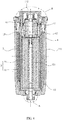
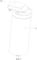
FIG. 1 is a structure diagram of the composite filter assembly according to an exemplary embodiment of the present disclosure; -
FIG. 2 is a front view of the composite filter assembly shown inFIG. 1 ; -
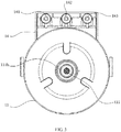
FIG. 3 is an upward view of the composite filter assembly shown inFIG. 2 ; -
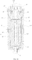
FIG. 4 is a cross section view of the composite filter assembly shown inFIG. 2 ; -
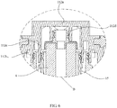
FIG. 5 is an exploded diagram of the portion A shown inFIG. 4 ; -
FIG. 6 is an exploded diagram of the portion B shown inFIG. 4 ; -
FIG. 7 is a structure diagram of the composite filter assembly according to another exemplary embodiment of the present disclosure; -
FIG. 8 is a front view of the composite filter assembly shown inFIG. 7 ; -
FIG. 9 is an upward view of the composite filter assembly shown inFIG. 8 ; -
FIG. 10 is a cross section view of the composite filter assembly shown inFIG. 8 ; -
FIG. 11 is an exploded diagram of the portion C shown inFIG. 10 ; -
FIG. 12 is an exploded diagram of the portion D shown inFIG. 10 . - The realization of the aim, functional characteristics, advantages of the present disclosure are further described specifically with reference to the accompanying drawings and embodiments.
- The technical solutions of the embodiments of the present disclosure will be clearly and completely described in the following with reference to the accompanying drawings. It is obvious that the embodiments to be described are only a part rather than all of the embodiments of the present disclosure. All other embodiments obtained by persons skilled in the art based on the embodiments of the present disclosure without creative efforts shall fall within the protection scope of the present disclosure.
- It is to be understood that, all the directional instructions of in the present disclosure (such as top, down, left, right, front, back......) can only be used for explaining relative position relations, moving condition of the elements under a special form (referring to figures), and so on, if the special form changes, the directional instructions changes accordingly.
- In addition, the descriptions, such as the "first", the "second" in the present disclosure, can only be used for describing the aim of description, and cannot be understood as indicating or suggestting relative importance or impliedly indicating the number of the indicated technical character. Therefore, the character indicated by the "first", the "second" can express or impliedly include at least one character. In addition, the technical proposal of each exemplary embodiment can be combined with each other, however the technical proposal must base on that the ordinary skill in that art can realize the technical proposal, when the combination of the technical proposals occurs contradiction or cannot realize, it should consider that the combination of the technical proposals does not existed, and is not contained in the protection scope required by the present disclosure.
- The present disclosure provides a composite filter assembly, which is applied to a water purification system.
- In an exemplary embodiment of the present disclosure, referring to
FIGS. 1-5 , the composite filter assembly includes ahousing 1, and a composite filter defined in thehousing 1, thehousing 1 defines a raw water inlet (not shown), an initialfiltered water outlet 111b, apressurized water inlet 122, a pure water outlet (not shown), and a waste water outlet (not shown), the composite filter includes apre-posed filter 2, amembrane filter 3, and apost-posed filter 4, thepre-posed filter 2 and themembrane filter 3 are defined in a manner from outside to inside, and spaced from each other, thepost-posed filter 4 is connected with themembrane filter 3 and located at a downstream position of themembrane filter 3;
the initialfiltered water outlet 111b is communicated with an outlet end of thepre-posed filter 2, thepressurized water inlet 122 is communicated with an inlet end of themembrane filter 3; and
the outlet end of thepre-posed filter 2 is adjacent to the inlet end of themembrane filter 3, the initialfiltered water outlet 111b is an annular opening which surrounds thepressurized water inlet 122. - It is to be understood that, the
pre-posed filter 2, themembrane filter 3, and thepost-posed filter 4 are integrated into a composite filter, as such the complete appliance is miniaturized, the number of the connectors and the risk of leakage are reduced. Thepre-posed filter 2 can be a PAC (PP And C, PP cotton and activated carbon composite filter)pre-posed filter 2, for example, thepre-posed filter 2 includes a PP non-woven fabric winding layer (the precision of the PP non-woven fabric winding layer can be 5um) and an activated carbon fiber winding layer which are successively arranged from outside to inside along a radial direction. Thepre-posed filter 2 can effectively remove rust and sediment in the water, and can adsorb color, smell, some organic contaminants, and chlorine in water, to ensure the water flowing into themembrane filter 3 has a good quality, and improve the lifespan of themembrane filter 3. Thepost-posed filter 4 can be an activated carbon layer, for example, thepost-posed filter 4 can be an activated carbon rod. Thepost-posed filter 4 can effectively remove volatile organic compounds, and residual chlorine, and can retain the minerals, such as, trace calcium, silicic acid, carbonate, and so on, as such the taste of the filtered water is sweet and soft. In addition, in the exemplary embodiment, the water purification system applying the composite filter assembly further includes a booster pump (not shown) and a waste water solenoid valve (not shown); the booster pump is located at a downstream position of thepre-posed filter 2, as such the water is filtered by thepre-posed filter 2 first, and then flows into the booster pump, to reduce the risk of blocking the booster pump, improve the lifespan and the reliability of the water purification system. The waste water solenoid valve is communicated with the waste water outlet, the waste water solenoid valve can be used for adjusting the ratio of the waste water, to balance the working pressure of the water purification system. - The technical solutions of the present disclosure can be applied to the large flux water purifier, the
pre-posed filter 2, themembrane filter 3, and thepost-posed filter 4 are integrated into a composite filter, as such the complete appliance is miniaturized, the number of the connectors and the risk of leakage are reduced. And, the initialfiltered water outlet 111b connected with the booster pump is configured to surround thepressurized water inlet 122, therefore the booster pump can be directly connected with the initialfiltered water outlet 111b and thepressurized water inlet 122 after passing through a connector, as such there is no need to introduce a connecting pipe, etc. The mounting of the complete appliance is simplified, the mounting efficiency of the water purifier is improved. - Furthermore, the
post-posed filter 4 is located upon thepre-posed filter 2 and themembrane filter 3; the initialfiltered water outlet 111b and thepressurized water inlet 122 are both defined at the lower end surface of thehousing 1. In the exemplary embodiment, the raw water inlet, the pure water outlet, and the waste water outlet are all arranged at the top end of thehousing 1. It is to be understood that, the structures, such as, booster pump and the waste water solenoid valve, are respectively arranged at the top end and the lower end of the composite filter assembly, therefore, the structures of the water purification system are properly arranged, and during the mounting process of the structures, the booster pump would not strike the other structures. It is to be understood that, the present disclosure is not limited to this, in another exemplary embodiment, the initialfiltered water outlet 111b and thepressurized water inlet 122 are arranged at a top end surface of thehousing 1, while the raw water inlet, the pure water outlet, and the waste water outlet are all arranged at the lower end of thehousing 1. - Furthermore, referring to
FIGS. 3-5 , thepressurized water inlet 122 is circular-shaped, and located at a center position of the lower end surface of the housing, the initialfiltered water outlet 111b and thepressurized water inlet 122 are concentric. It is to be understood that, it is easy and convenient to manufacture the circular opening, then thepressurized water inlet 122 and thepressurized water inlet 111b are concentric, as such water can flow in or flow out uniformly in each direction, so as to ensure that the booster pump can be tightly connected with thepressurized water inlet 111b and thepressurized water inlet 122. It is to be understood that, the present disclosure is not limited to this, in another exemplary embodiment, a center of thepressurized water inlet 122 and a center of thepressurized water inlet 111b are not concentric, in addition, thepressurized water inlet 122 can also have other shape, for example, thepressurized water inlet 122 is rectangular. - Furthermore, a radius of the
pressurized water inlet 122 is 10mm to 20mm, a radius of a circle defined by the outer peripheral edge of the initialfiltered water outlet 111b is 25mm to 35mm. It is to be understood that, the radius of thepressurized water inlet 122 corresponds to the size of thepressurized water inlet 122, a value of subtracting the radius of thepressurized water inlet 122 from the radius of the circle of the outer peripheral edge of the initialfiltered water outlet 111b can be defined as the size of the initialfiltered water outlet 111b. It is not good for ensure the pressure of the water circulation in the composite filter composite and the seal of the connecting positions among the two openings and the booster pump when the size of the initialfiltered water outlet 111b and the size of thepressurized water inlet 122 are too large or too small. - Furthermore, the
housing 1 includes anouter housing 11, and aninner housing 12 received in theouter housing 11, thepre-posed filter 2 is defined between the inner surface of theouter housing 11 and the outer surface of theinner housing 12, themembrane filter 3 is received in theinner housing 12, thepost-posed filter 4 is defined at an up end of theinner housing 12; a lower end surface of theouter housing 11 defines a first opening, the periphery of the first opening extends downwards to form a firstannular rib 111a; a lower end surface of theinner housing 12 defines a second opening, a projection of the second opening along an up-down direction is located in the first opening, the periphery of the second opening extends downwards to form a secondannular rib 121, the secondannular rib 121 extends into the firstannular rib 111a; and an inner circumference surface of the firstannular rib 111a and an outer circumferential surface of the secondannular rib 121 cooperatively form the initialfiltered water outlet 111b, the inner circumference surface of the secondannular rib 121 defines thepressurized water inlet 122. - It is to be understood that, it is easy, simple, and quick to manufacture the
pressurized water inlet 122 and the initialfiltered water outlet 111b, and it is also simple to mount the composite filter assembly. In the exemplary embodiment, theouter housing 11 includes abody 111 and acover 112 configured to cover thebody 111, thecover 112 defines the raw water inlet, the pure water outlet, and the waste water outlet, in detail, the raw water inlet can be configured to communicate with the top end of a portion between theouter housing 11 and theinner housing 12, raw water can flow into from the top end, and then can be filtered by thepre-posed filter 2, and flow out from the lower end of the portion between theouter housing 11 and theinner housing 12, then the filtered water can flow into the booster pump to be pressurized, the pressurized water can flow into theinner housing 12 through thepressurized water inlet 122, to be filtered. In addition, in the exemplary embodiment, the composite filter assembly further includes anannular end cover 13, theend cover 13 is defined in the lower end of the portion between theouter housing 11 and theinner housing 12, a top end surface of theend cover 13 can be configured to support thepre-posed filter 2. Of course, in another exemplary embodiment, thepre-posed filter 2 can be fixed between theouter housing 11 and theinner housing 12 through other methods, the present disclosure does not limit the fixing method. It is to be understood that, the present disclosure is not limited to this, in another exemplary embodiment, thepressurized water inlet 122 and the initialfiltered water outlet 111b are both defined at the lower end surface of theouter housing 11, while the initialfiltered water outlet 111b is an annular opening which surrounds thepressurized water inlet 122. - Furthermore, the outer circumferential surface of the first
annular rib 111a and the outer circumferential surface of the secondannular rib 121 both define a sealing structure, the sealing structure is configured as an adaptor (not shown) which is tightly connected to a booster pump of the water purification system. In an exemplary embodiment, the booster pump is connected with thepressurized water inlet 122 and the initialfiltered water outlet 111b through an adaptor, the adaptor includes an outer ring element and an inner ring element which is coaxial with the outer ring element, the inner circumference surface of the inner ring element is connected with the outer circumferential surface of the secondannular rib 121 in the sealing manner, the inner circumference surface of the outer ring element is connected with the inner circumference surface of the firstannular rib 111a in the sealing manner, of course, in another exemplary embodiment, the booster pump is connected with the firstannular rib 111a and the secondannular rib 121 through other modes, the present disclosure is not limited to this. - Furthermore, the sealing structures include one sealing
annular groove 111c defined at the outer circumferential surface of the firstannular rib 111a and asealing element 111d received in the sealingannular groove 111c, and another sealingannular groove 111c defined at the outer circumferential surface of the secondannular rib 121 and another sealingelement 111d received in the another sealingannular groove 111c. It is to be understood that, the cooperation between the sealingannular groove 111c and thesealing element 111d is a common technical mean broadly used in the water purifier technology, and the cooperation has the advantages of good sealability, simple process, etc. Of course, in another exemplary embodiment, the sealing structures can also include elastic sealing rings defined on the circumference surface of the firstannular rib 111a and the secondannular rib 121, the present disclosure does not limit the type of the sealing structure. In addition, in the exemplary embodiment, the sealingelement 111d includes at least two overlapped O type rings, it is to be understood that, the O type rings are easy to obtain, and cheap, as such it is beneficial to reduce the cost of the water purification system; of course, in another exemplary embodiment, the sealingelement 111d can also be the sealant coated in the sealingannular groove 111c, the present disclosure does not limit the type of the sealingelement 111d. - Furthermore, a
connector 14 configured to connect with an external structure is defined at a top end of theouter housing 11, araw water connector 141, apure water connector 142, and awaste water connector 143 are all defined on theconnector 14 in a parallel manner, theraw water connector 141 communicates with the raw water inlet, thepure water connector 142 communicates with the pure water outlet, thewaste water connector 143 communicates with the waste water outlet. It is to be understood that, the connectors are arranged together in a compact fashion, it is beneficial to connect with the external structure, such as the waste water solenoid valve, etc. The mounting process is also simplified. In the exemplary embodiment, theconnector 14 is located on the top end surface of thecover 112, and theconnector 14 includes a mounting element protruded from thecover 112, a lower end surface of the mounting element protrudes theraw water connector 141, thepure water connector 142, and thewaste water connector 143 which are arranged from left to right.; of course, in another exemplary embodiment, theconnector 14 can also defined at the outer circumferential surface of the top end of theouter housing 11, the present disclosure does not limit the position of theconnector 14. - Furthermore, the
membrane filter 3 includes acentral collecting pipe 32, and amembrane filter body 31 coiled around thecentral collecting pipe 32, thepressurized water inlet 122 is communicated with an inlet end of themembrane filter body 3, a wall of thecentral collecting pipe 32 defines a plurality of communicatingports 321 which communicate with an outlet end of themembrane filter body 31, a top end of thecentral collecting pipe 32 is communicated with an inlet end of thepost-posed filter 4. It is to be understood that, the inner cavity of themembrane filter body 31 is reasonably used, which can be configured to introduce the pressurized water, and expel the secondary filtered water. In detail, the water flowing from thepressurized water inlet 122 are introduced to a position adjacent to the inner circumference surface of theinner housing 12, as such the water can flow into themembrane filter 3 to be secondary filtered, and the waste water can pass through the top end of themembrane filter body 31 and then flow out through the waste water outlet, the secondary filtered water can flow into thecentral collecting pipe 32 through the communicatingports 321, and then the secondary filtered water can be introduced to the inlet end of thepost-posed filter 4. - Furthermore, referring to
FIGS. 4 ,6 , the composite filter assembly further includes a hollowed connectinghousing 15, at least a portion of the connectinghousing 15 is defined in a top end of theinner housing 12, and the top end of thecentral collecting pipe 32 is communicated with an inner cavity of the connectinghousing 15; and an outer surface of the connectinghousing 15 and an inner surface of theinner housing 12 cooperatively define a wastewater flow channel 16 for leading waste water from themembrane filter body 31 to the waste water outlet; thepost-posed filter 4 is located in the connectinghousing 15, thepost-posed filter 4 and an inner surface of the connectinghousing 15 cooperatively define a flow channel, an inner cavity of thepost-posed filter 4 defines a purewater flow channel 17 for leading pure water to the pure water outlet. - In the exemplary embodiment, the connecting
housing 15 includes a barrel-shaped wall, and an annular connector located at a top end surface of the barrel-shaped wall, thecover 112 includes acover body 112a configured to cover thebody 111, and a firstannular element 112b, a secondannular element 112c, and a thirdannular element 112d which are all arranged from the outside to inside and extended downwards from the lower end surface of thecover body 112a. An inner circumference surface of the firstannular element 112b is connected with the outer circumferential surface of theinner housing 12 in the sealing mode, an inner circumference surface of the secondannular element 112c is connected with the outer circumferential surface of the barrel-shaped wall in the sealing mode, an inner circumference surface of the thirdannular element 112d is connected with the outer circumferential surface of the annular connector in the sealing mod, as such, the waste water filtered through themembrane filter body 31 can flow to the waste water outlet after passing through the wastewater flow channel 16 between the inner circumference surface ofinner housing 12 and the outer circumferential surface of secondannular element 112c; the secondary filtered water filtered through themembrane filter body 31 can flow into the barrel-shaped wall through thecentral collecting pipe 32, and the secondary filtered water is filtered through thepost-posed filter 4 and then flows out to the pure water outlet through the purewater flow channel 17 formed by the inner cavity of thepost-posed filter 4, as such the whole water purification process is completed. It is to be understood that, the present disclosure is not limited to this, in another exemplary embodiment, the connectinghousing 15 can have other shape or design, to form the wastewater flow channel 16 and the purewater flow channel 17. - The present disclosure also provide a water purification system, the water purification system includes a booster pump, a water storage device, and a composite filter assembly. The detail structure of the composite filter assembly can be referred to the above description. One end of the booster pump is connected with the initial filtered water outlet, the other end of the booster pump is connected with the pressurized water inlet. As the water purification system includes all technical proposals of all the exemplary embodiments, and the achieved technical effects are the same, no need to repeated again.
- The present disclosure also provides a composite filter assembly, which is applied to the water purification system.
- In the exemplary embodiment, referring to
FIGS. 7-11 , the composite filter assembly includes a housing 1', and a composite filter defined in the housing 1', the housing 1' defines a raw water inlet (not shown), an initialfiltered water outlet 111b', a pressurized water inlet 122', a water storage port (not shown), a pure water outlet (not shown), and a waste water outlet (not shown), the composite filter includes a pre-posed filter 2', a membrane filter 3', and a post-posed filter 4', the membrane filter 3' is received in the pre-posed filter 2', and separated from the pre-posed filter 2', the post-posed filter 4' is connected with the membrane filter 3' and located at a downstream position of the membrane filter 3';
the initialfiltered water outlet 111b' is communicated with an outlet end of the pre-posed filter 2', the pressurized water inlet 122' is communicated with an inlet end of the membrane filter 3', the water storage port is communicated with the outlet end of the membrane filter 3', and communicated with the inlet end of the post-posed filter 4'; and
the outlet end of the pre-posed filter 2' is adjacent to the inlet end of the membrane filter 3', the initialfiltered water outlet 111b' is an annular opening which surrounds the pressurized water inlet 122'. - It is to be understood that, the pre-posed filter 2', the membrane filter 3', and the post-posed filter 4' are integrated into a composite filter, as such the complete appliance is miniaturized, the number of the connectors and the risk of leakage are reduced. The pre-posed filter 2' can be a PAC (PP And C, PP cotton and activated carbon composite filter) pre-posed filter 2', for example, the pre-posed filter 2' includes a PP non-woven fabric winding layer (the precision of the PP non-woven fabric winding layer can be 5um) and an activated carbon fiber winding layer which are successively arranged from outside to inside along a radial direction. The pre-posed filter 2' can effectively remove rust and sediment in the water, and can adsorb color, smell, some organic contaminants, and chlorine in water, to ensure the water flowing into the membrane filter 3' has a good quality, and improve the lifespan of the membrane filter 3'. The post-posed filter 4' can be an activated carbon layer, for example, the
post-posed filter 4 can be an activated carbon rod. The post-posed filter 4' can effectively remove volatile organic compounds, and residual chlorine, and can retain the minerals, such as, trace calcium, silicic acid, carbonate, and so on, as such the taste of the filtered water is sweet and soft. In addition, in the exemplary embodiment, the water purification system applying the composite filter assembly further includes a booster pump (not shown), a waste water solenoid valve (not shown), and a water storage device (not shown); the booster pump is located at a downstream position of the pre-posed filter 2', as such the water is filtered by the pre-posed filter 2' first, and then flows into the booster pump, to reduce the risk of blocking the booster pump, improve the lifespan and the reliability of the water purification system. The waste water solenoid valve is communicated with the waste water outlet, the waste water solenoid valve can be used for adjusting the ratio of the waste water, to balance the working pressure of the water purification system; the water storage device is connected with the water storage port, the water storage device is configured to store the pure water from the water storage port. The waste water solenoid valve is connected with the waste water outlet. As such, the pure water can be stored in the water storage device through the water storage device, when the water pressure is not enough, the composite filter assembly can also meet the user's large flux demand. - The technical solutions of the present disclosure can be applied to the small flux water purifier, the pre-posed filter 2', the membrane filter 3', and the post-posed filter 4' are integrated into a composite filter, as such the complete appliance is miniaturized, the number of the connectors and the risk of leakage are reduced. And, the initial
filtered water outlet 111b' connected with the booster pump is configured to surround the pressurized water inlet 122', therefore the booster pump can be directly connected with the initialfiltered water outlet 111b' and the pressurized water inlet 122' after passing through a connector, as such there is no need to introduce a connecting pipe, etc. The mounting of the complete appliance is simplified, the mounting efficiency of the water purifier is improved. - Furthermore, the post-posed filter 4' is located upon the pre-posed filter 2' and the membrane filter 3'; the initial
filtered water outlet 111b' and the pressurized water inlet 122' are both defined at the lower end surface of the housing 1'. In the exemplary embodiment, the raw water inlet, the water storage port, the pure water outlet, and the waste water outlet are all arranged at the top end of the housing 1'. It is to be understood that, the structures, such as, booster pump and the water storage device, are respectively arranged at the top end and the lower end of the composite filter assembly, therefore, the structures of the water purification system are properly arranged, and during the mounting process of the structures, the booster pump would not strike the other structures. It is to be understood that, the present disclosure is not limited to this, in another exemplary embodiment, the initialfiltered water outlet 111b' and the pressurized water inlet 122' are arranged at a top end surface of the housing 1', while the raw water inlet, the water storage port, the pure water outlet, and the waste water outlet are all arranged at the lower end of the housing 1'. - Furthermore, referring to
FIGS. 9-11 , the pressurized water inlet 122' is circular-shaped, and located at a center position of the lower end surface of the housing, the initialfiltered water outlet 111b' and the pressurized water inlet 122' are concentric. It is to be understood that, it is easy and convenient to manufacture the circular opening, then the pressurized water inlet 122' can be configured to be coaxial with thepressurized water inlet 111b', as such water can flow in or flow out uniformly in each direction, so as to ensure that the booster pump can be tightly connected with thepressurized water inlet 111b' and the pressurized water inlet 122'. It is to be understood that, the present disclosure is not limited to this, in another exemplary embodiment, a center of the pressurized water inlet 122' can be configured to be not coaxial with a center of thepressurized water inlet 111b', in addition, the pressurized water inlet 122' can also have other shape, for example, the pressurized water inlet 122' is rectangular. - Furthermore, a radius of the pressurized water inlet 122' is 10mm to 20mm, a radius of a circle defined by the outer peripheral edge of the initial
filtered water outlet 111b' is 25mm to 35mm. It is to be understood that, the radius of the pressurized water inlet 122' corresponds to the size of the pressurized water inlet 122', a value of subtracting the radius of the pressurized water inlet 122' from the radius of a circle of the outer peripheral of the initialfiltered water outlet 111b' can be defined as the size of the initialfiltered water outlet 111b'. It is not good for ensure the pressure of the water circulation in the composite filter composite and the seal of the connecting positions among the two openings and the booster pump when the size of the initialfiltered water outlet 111b' and the size of the pressurized water inlet 122' are too large or too small. - Furthermore, the housing 1' includes an outer housing 11', and an inner housing 12' received in the outer housing 11', the pre-posed filter 2' is defined between the inner surface of the outer housing 11' and the outer surface of the inner housing 12', the membrane filter 3' is received in the inner housing 12', the post-posed filter 4' is defined at a top end of the inner housing 12'; a lower end surface of the outer housing 11' defines a first opening, the periphery of the first opening extends downwards to form a first
annular rib 111a'; a lower end surface of the inner housing 12' defines a second opening, a projection of the second opening along an up-down direction is defined in the first opening, the periphery of the second opening extends downwards to form a second annular rib 121', the second annular rib 121' extends into the firstannular rib 111a'; and an inner circumference surface of the firstannular rib 111a' and an outer circumferential surface of the second annular rib 121' cooperatively form the initialfiltered water outlet 111b', an inner circumference surface of the second annular rib 121' defines the pressurized water inlet 122'. - It is to be understood that, it is easy, simple, and quick to manufacture the pressurized water inlet 122' and the initial
filtered water outlet 111b', and it is also simple to mount the composite filter assembly. In the exemplary embodiment, the outer housing 11' includes a body 111' and a cover 112' configured to cover the body 111', the cover 112' defines the raw water inlet, the water storage port, the pure water outlet, and the waste water outlet, in detail, the raw water inlet can be configured to communicate with the top end of a portion between the outer housing 11' and the inner housing 12', raw water can flow into from the top end, and then can be filtered by the pre-posed filter 2', and flow out from the lower end of the portion between theouter housing 11 and the inner housing 12', then the filtered water can flow into the booster pump to be pressurized, the pressurized water can flow into the inner housing 12' through the pressurized water inlet 122', to be filtered. In addition, in the exemplary embodiment, the composite filter assembly further includes an annular end cover 13', the end cover 13' is defined in the lower end of the portion between theouter housing 11 and the inner housing 12', a top end surface of the end cover 13' can be configured to support the pre-posed filter 2'. Of course, in another exemplary embodiment, the pre-posed filter 2' can be fixed between the outer housing 11' and the inner housing 12' through other methods, the present disclosure does not limit the fixing method. It is to be understood that, the present disclosure is not limited to this, in another exemplary embodiment, the pressurized water inlet 122' and the initialfiltered water outlet 111b' are both defined at the lower end surface of the outer housing 11', while the initialfiltered water outlet 111b' is an annular opening which surrounds the pressurized water inlet 122'. - Furthermore, the outer circumferential surface of the first
annular rib 111a' and the outer circumferential surface of the second annular rib 121' both define a sealing structure, the sealing structure is configured as an adaptor (not shown) which is tightly connected to a booster pump of the water purification system. In an exemplary embodiment, the booster pump is connected with the pressurized water inlet 122' and the initialfiltered water outlet 111b' through an adaptor, the adaptor includes an outer ring element and an inner ring element which is coaxial with the outer ring element, the inner circumference surface of the inner ring element is connected with the outer circumferential surface of the second annular rib 121' in the sealing manner, the inner circumference surface of the outer ring element is connected with the inner circumference surface of the firstannular rib 111a' in the sealing manner, of course, in another exemplary embodiment, the booster pump is connected with the firstannular rib 111a' and the second annular rib 121' through other modes, the present disclosure is not limited to this. - Furthermore, the sealing structures include one sealing
annular groove 111c' defined at the outer circumferential surface of the firstannular rib 111a' and asealing element 111d' received in the sealingannular groove 111c', and another sealingannular groove 111c' defined at the outer circumferential surface of the second annular rib 121' and another sealingelement 111d' received in the another sealingannular groove 111c'. It is to be understood that, the cooperation between the sealingannular groove 111c' and thesealing element 111d' is a common technical mean broadly used in the water purifier technology, and the cooperation has the advantages of good sealability, simple process, etc. Of course, in another exemplary embodiment, the sealing structures can also include elastic sealing rings defined on the circumference surface of the firstannular rib 111a' and the second annular rib 121', the present disclosure does not limit the type of the sealing structure. In addition, in the exemplary embodiment, the sealingelement 111d' includes at least two overlapped O type rings, it is to be understood that, the O type rings are easy to obtain, and cheap, as such it is beneficial to reduce the cost of the water purification system; of course, in another exemplary embodiment, the sealingelement 111d' can also be the sealant coated in the sealingannular groove 111c', the present disclosure does not limit the type of the sealingelement 111 d'. - Furthermore, a
connector 14' configured to connect with an external structure is defined at a top end of the outer housing 11', a raw water connector 141', a water storage connector 142', a pure water connector 143', and a waste water connector 144' are all defined on theconnector 14' in a parallel manner, the raw water connector 141' communicates with the raw water inlet, the water storage connector 142' communicates with the water storage port, the pure water connector 143' communicates with the pure water outlet, the waste water connector 144' communicates with the waste water outlet. It is to be understood that, the connectors are arranged together in a compact fashion, it is beneficial to connect with the external structure, such as the waste water solenoid valve, etc. The mounting process is also simplified. In the exemplary embodiment, theconnector 14' is located on the top end surface of the cover 112', and theconnector 14' includes a mounting element protruded from the cover 112', a lower end surface of the mounting element protrudes the raw water connector 141', the water storage connector 142', the pure water connector 143', and the waste water connector 144' which are arranged from left to right.; of course, in another exemplary embodiment, theconnector 14' can also defined at the outer circumferential surface of the top end of the outer housing 11', the present disclosure does not limit the position of theconnector 14'. - Furthermore, the membrane filter 3' includes a central collecting pipe 32', and a membrane filter body 31' coiled around the central collecting pipe 32', the pressurized water inlet 122' is communicated with an inlet end of the membrane filter body 3', a wall of the central collecting pipe 32' defines a plurality of communicating ports 321' which are communicated with an outlet end of the membrane filter body 31', a top end of the central collecting pipe 32' is communicated with an inlet end of the post-posed filter 4' and the water storage port. It is to be understood that, the inner cavity of the membrane filter body 31' is reasonably used, which can be configured to introduce the pressurized water, and expel the secondary filtered water. In detail, the water flowing from the pressurized water inlet 122' are introduced to a position adjacent to the inner circumference surface of the inner housing 12', as such the water can flow into the membrane filter 3' to be secondary filtered, and the waste water can pass through the top end of the membrane filter body 31' and then flow out through the waste water outlet, the secondary filtered water can flow into the central collecting pipe 32' through the communicating ports 321', and then the secondary filtered water can be introduced to the inlet end of the post-posed filter 4'.
- Furthermore, referring to
FIGS. 10 ,12 , the composite filter assembly further includes a hollowed connecting housing 15', at least a portion of the connecting housing 15' is defined in a top end of the inner housing 12', and the top end of the central collecting pipe 32' is communicated with an inner cavity of the connecting housing 15'; and an outer surface of the connecting housing 15' and an inner surface of the inner housing 12' cooperatively define a waste water flow channel 16' for leading waste water from the membrane filter body 31' to the waste water outlet; thepost-posed filter 4 is located in the connecting housing 15', the post-posed filter 4' and an inner surface of the connecting housing 15' cooperatively define a water storage channel 17' for leading water flow from the top end of the central collecting pipe 32' to the water storage port, an inner cavity of the post-posed filter 4' defines a purewater flow channel 18 for leading pure water to the pure water outlet. - In the exemplary embodiment, the connecting housing 15' includes a barrel-shaped wall, and an annular connector located at a top end surface of the barrel-shaped wall, the cover 112' includes a
cover body 112a' configured to cover the body 111', and a firstannular element 112b', a secondannular element 112c', and a thirdannular element 112d' which are all arranged from the outside to inside and extended downwards from the lower end surface of thecover body 112a'. An inner circumference surface of the first annular element 112b' is connected with the outer circumferential surface of the inner housing 12' in the sealing mode, an inner circumference surface of the second annular element 112c' is connected with the outer circumferential surface of the barrel-shaped wall in the sealing mode, an inner circumference surface of the third annular element 112d' is connected with the outer circumferential surface of the annular connector in the sealing mod, as such, the waste water filtered through the membrane filter body 31' can flow to the waste water outlet after passing through the waste water flow channel 16' between the inner circumference surface of inner housing 12' and the outer circumferential surface of second annular element 112c'; the secondary filtered water filtered through the membrane filter body 31' can flow into the barrel-shaped wall through the central collecting pipe 32', a part of the secondary filtered water can flow to the water storage port from the water storage channel 17' between the inner circumference surface of the second annular element 112c' and the inner circumference surface of the barrel-shaped wall, the other part of the secondary filtered water is filtered through the post-posed filter 4' and then flows out to the pure water outlet through the pure water flow channel 18' formed by the inner cavity of the post-posed filter 4', as such the whole water purification process is completed. It is to be understood that, the present disclosure is not limited to this, in another exemplary embodiment, the connecting housing 15' can have other shape or design, to form the waste water flow channel 16', the water storage channel 17' and the pure water flow channel 18'. - The present disclosure also provide a water purification system, the water purification system includes a booster pump, a water storage device, and a composite filter assembly. The detail structure of the composite filter assembly can be referred to the above description. One end of the booster pump is connected with the initial filtered water outlet, the other end of the booster pump is connected with the pressurized water inlet, the water storage device is connected with the water storage port. As the water purification system includes all technical proposals of all the exemplary embodiments, and the achieved technical effects are the same, no need to repeated again.
- The foregoing description merely depicts some illustrative embodiments of the present application and therefore is not intended to limit the scope of the application. An equivalent structural or flow changes made by using the content of the specification and drawings of the present application, or any direct or indirect applications of the disclosure on any other related fields shall all fall in the scope of the application.
Claims (20)
- A composite filter assembly, applied to a water purification system, wherein, the composite filter assembly comprises a housing, and a composite filter defined in the housing, the housing defines a raw water inlet, an initial filtered water outlet, a pressurized water inlet, a pure water outlet, and a waste water outlet, the composite filter comprises a pre-posed filter, a membrane filter, and a post-posed filter, the pre-posed filter and the membrane filter are defined in a manner from outside to inside, and spaced from each other, the post-posed filter is connected with the membrane filter and located at a downstream position of the membrane filter;
the initial filtered water outlet is communicated with an outlet end of the pre-posed filter, the pressurized water inlet is communicated with an inlet end of the membrane filter; and
the outlet end of the pre-posed filter is adjacent to the inlet end of the membrane filter, the initial filtered water outlet is an annular opening which surrounds the pressurized water inlet. - The composite filter assembly according to claim 1, wherein the post-posed filter is located upon the pre-posed filter and the membrane filter; and
the initial filtered water outlet and the pressurized water inlet are both defined at a lower end surface of the housing. - The composite filter assembly according to claim 2, wherein the pressurized water inlet is circular-shaped, and located at a center position of the lower end surface of the housing, the initial filtered water outlet and the pressurized water inlet are concentric.
- The composite filter assembly according to claim 2, wherein a radius of the pressurized water inlet is 10mm to 20mm, a radius of a circle defined by the outer peripheral edge of the initial filtered water outlet is 25mm to 35mm.
- The composite filter assembly according to claim 2, wherein the housing comprises an outer housing, and an inner housing received in the outer housing, the pre-posed filter is defined between the inner surface of the outer housing and the outer surface of the inner housing, the membrane filter is received in the inner housing, the post-posed filter is defined at an up end of the inner housing;
a lower end surface of the outer housing defines a first opening, the periphery of the first opening extends downwards to form a first annular rib; a lower end surface of the inner housing defines a second opening, a projection of the second opening along an up-down direction is located in the first opening, the periphery of the second opening extends downwards to form a second annular rib, the second annular rib extends into the first annular rib; and
an inner circumference surface of the first annular rib and an outer circumferential surface of the second annular rib cooperatively form the initial filtered water outlet, the inner circumference surface of the second annular rib defines the pressurized water inlet. - The composite filter assembly according to claim 5, wherein an outer circumferential surface of the first annular rib and the outer circumferential surface of the second annular rib both define a sealing structure, the sealing structure is configured as an adaptor which is tightly connected to a booster pump of the water purification system.
- The composite filter assembly according to claim 6, wherein the sealing structures comprise one sealing annular groove defined at the outer circumferential surface of the first annular rib and one sealing element defined in the sealing annular groove, and another sealing annular groove located at the outer circumferential surface of the second annular rib and another sealing element defined in the another sealing annular groove.
- The composite filter assembly according to claim 5, wherein a connector configured to connect with an external structure is defined at a top end of the outer housing, a raw water connector, a pure water connector, and a waste water connector are all defined on the connector in a parallel manner, the raw water connector communicates with the raw water inlet, the pure water connector communicates with the pure water outlet, the waste water connector communicates the waste water outlet.
- The composite filter assembly according to claim 5, wherein the membrane filter comprises a central collecting pipe, and a membrane filter body coiled around the central collecting pipe, the pressurized water inlet is communicated with an inlet end of the membrane filter body, a wall of the central collecting pipe defines a plurality of communicating ports which communicate with an outlet end of the membrane filter body, a top end of the central collecting pipe is communicated with an inlet end of the post-posed filter.
- The composite filter assembly according to claim 9, wherein the composite filter assembly further comprises a hollowed connecting housing, at least a portion of the connecting housing is defined in a top end of the inner housing, and the top end of the central collecting pipe is communicated with an inner cavity of the connecting housing; and
an outer surface of the connecting housing and an inner surface of the inner housing cooperatively define a waste water flow channel for leading waste water from the membrane filter body to the waste water outlet; the post-posed filter is located in the connecting housing, the post-posed filter and an inner surface of the connecting housing cooperatively define a flow channel, an inner cavity of the post-posed filter defines a pure water flow channel for leading pure water to the pure water outlet. - A water purification system, wherein, the water purification system comprises a booster pump and a composite filter assembly, the composite filter assembly comprises a housing, and a composite filter defined in the housing, the housing defines a raw water inlet, an initial filtered water outlet, a pressurized water inlet, a pure water outlet, and a waste water outlet, the composite filter comprises a pre-posed filter, a membrane filter, and a post-posed filter, the pre-posed filter and the membrane filter are defined in a manner from outside to inside, and spaced from each other, the post-posed filter is connected with the membrane filter and located at a downstream position of the membrane filter;
the initial filtered water outlet is communicated with an outlet end of the pre-posed filter, the pressurized water inlet is communicated with an inlet end of the membrane filter;
the outlet end of the pre-posed filter is adjacent to the inlet end of the membrane filter, the initial filtered water outlet is an annular opening which surrounds the pressurized water inlet; and
one end of the booster pump is connected with the initial filtered water outlet, the other end of the booster pump is connected with the pressurized water inlet. - A composite filter assembly, applied to a water purification system, wherein, the composite filter assembly comprises a housing, and a composite filter defined in the housing, the housing defines a raw water inlet, an initial filtered water outlet, a pressurized water inlet, a water storage port, a pure water outlet, and a waste water outlet, the composite filter comprises a pre-posed filter, a membrane filter, and a post-posed filter, the pre-posed filter and the membrane filter are defined in a manner from outside to inside, and spaced from each other, the post-posed filter is connected with the membrane filter and located at a downstream position of the membrane filter;
the initial filtered water outlet is communicated with an outlet end of the pre-posed filter, the pressurized water inlet is communicated with an inlet end of the membrane filter, the water storage port is communicated with an outlet end of the membrane filter and inlet end of the post-posed filter; and
the outlet end of the pre-posed filter is adjacent to the inlet end of the membrane filter, the initial filtered water outlet is an annular opening which surrounds the pressurized water inlet. - The composite filter assembly according to claim 12, wherein the post-posed filter is located upon the pre-posed filter and the membrane filter; and
the initial filtered water outlet and the pressurized water inlet are both defined at a lower end surface of the housing. - The composite filter assembly according to claim 13, wherein the pressurized water inlet is circular-shaped, and located at a center position of the lower end surface of the housing, the initial filtered water outlet and the pressurized water inlet are concentric.
- The composite filter assembly according to claim 13, wherein the housing comprises an outer housing, and an inner housing received in the outer housing, the pre-posed filter is defined between the inner surface of the outer housing and the outer surface of the inner housing, the membrane filter is received in the inner housing, the post-posed filter is defined at an up end of the inner housing;
a lower end surface of the outer housing defines a first opening, the periphery of the first opening extends downwards to form a first annular rib; a lower end surface of the inner housing defines a second opening, a projection of the second opening along an up-down direction is located in the first opening, the periphery of the second opening extends downwards to form a second annular rib, the second annular rib extends into the first annular rib; and
an inner circumference surface of the first annular rib and an outer circumferential surface of the second annular rib cooperatively form the initial filtered water outlet, the inner circumference surface of the second annular rib defines the pressurized water inlet. - The composite filter assembly according to claim 15, wherein an outer circumferential surface of the first annular rib and the outer circumferential surface of the second annular rib both define a sealing structure, the sealing structure is configured as an adaptor which is tightly connected to a booster pump of the water purification system.
- The composite filter assembly according to claim 16, wherein the sealing structures comprise one sealing annular groove defined at the outer circumferential surface of the first annular rib and one sealing element defined in the sealing annular groove, and another sealing annular groove located at the outer circumferential surface of the second annular rib and another sealing element defined in the another sealing annular groove.
- The composite filter assembly according to claim 15, wherein a connector configured to connect with an external structure is defined at a top end of the outer housing, a raw water connector, a water storage connector, a pure water connector, and a waste water connector are all defined on the connector in a parallel manner, the raw water connector communicates with the raw water inlet, the water storage connector communicates with the water storage port, the pure water connector communicates with the pure water outlet, the waste water connector communicates with the waste water outlet.
- The composite filter assembly according to claim 15, wherein the membrane filter comprises a central collecting pipe, and a membrane filter body coiled around the central collecting pipe, the pressurized water inlet is communicated with an inlet end of the membrane filter body, a wall of the central collecting pipe defines a plurality of communicating ports which communicate with an outlet end of the membrane filter body, a top end of the central collecting pipe is communicated with and the water storage port and the inlet end of the post-posed filter.
- The composite filter assembly according to claim 19, wherein the composite filter assembly further comprises a hollowed connecting housing, at least a portion of the connecting housing is defined in a top end of the inner housing, and the top end of the central collecting pipe is communicated with an inner cavity of the connecting housing; and
an outer surface of the connecting housing and an inner surface of the inner housing cooperatively define a waste water flow channel for leading waste water from the membrane filter body to the waste water outlet; the post-posed filter is located in the connecting housing, the post-posed filter and an inner surface of the connecting housing cooperatively define a water storage flow channel for leading water from a top end of the central collecting pipe to the water storage port, an inner cavity of the post-posed filter defines a pure water flow channel for leading pure water to the pure water outlet.
Applications Claiming Priority (3)
| Application Number | Priority Date | Filing Date | Title |
|---|---|---|---|
| CN201721430486.8U CN207498155U (en) | 2017-10-30 | 2017-10-30 | Composite filter element assembly and water purification system |
| CN201721432072.9U CN207401250U (en) | 2017-10-30 | 2017-10-30 | Composite filter element component and water cleaning systems |
| PCT/CN2018/107583 WO2019085695A1 (en) | 2017-10-30 | 2018-09-26 | Composite filter element assembly and water purification system |
Publications (3)
| Publication Number | Publication Date |
|---|---|
| EP3549653A1 true EP3549653A1 (en) | 2019-10-09 |
| EP3549653A4 EP3549653A4 (en) | 2020-01-22 |
| EP3549653B1 EP3549653B1 (en) | 2021-05-12 |
Family
ID=66331350
Family Applications (1)
| Application Number | Title | Priority Date | Filing Date |
|---|---|---|---|
| EP18796819.3A Active EP3549653B1 (en) | 2017-10-30 | 2018-09-26 | Water purification system with composite filter element assembly |
Country Status (3)
| Country | Link |
|---|---|
| US (1) | US20190127255A1 (en) |
| EP (1) | EP3549653B1 (en) |
| WO (1) | WO2019085695A1 (en) |
Families Citing this family (6)
| Publication number | Priority date | Publication date | Assignee | Title |
|---|---|---|---|---|
| CA178682S (en) * | 2017-06-09 | 2019-02-08 | Blue Safety Gmbh | Water sanitizing unit |
| CN109911986A (en) * | 2019-02-13 | 2019-06-21 | 韩佳环保设备有限公司 | Integral type integrated water purifier filter core and water purifier |
| CN113476946B (en) * | 2021-08-23 | 2024-07-12 | 达格玛(厦门)环保科技有限公司 | Water purifier connecting piece and water purifier |
| JP7836394B2 (en) * | 2021-11-09 | 2026-03-26 | コーウェイ株式会社 | Composite filters and water purifiers containing them |
| DE102023204622A1 (en) * | 2023-05-17 | 2024-11-21 | Mahle International Gmbh | filter device |
| USD1072181S1 (en) * | 2024-03-02 | 2025-04-22 | Brio Water Technology, Inc. | Filter |
Family Cites Families (11)
| Publication number | Priority date | Publication date | Assignee | Title |
|---|---|---|---|---|
| US4992170A (en) * | 1990-04-03 | 1991-02-12 | Eastman Kodak Company | Reverse osmosis filter cartridge assembly |
| KR100494994B1 (en) * | 2003-08-29 | 2005-06-10 | 웅진코웨이주식회사 | Reverse osmotic water purifier having filter housing of unity type |
| CN104524861A (en) * | 2014-12-19 | 2015-04-22 | 佛山市顺德区美的饮水机制造有限公司 | Pretreatment filter core and integrated composite filter core with same |
| WO2016095401A1 (en) * | 2014-12-19 | 2016-06-23 | 佛山市顺德区美的饮水机制造有限公司 | Composite filter cartridge and water purification system having same |
| DE102015003162A1 (en) * | 2015-03-13 | 2016-09-15 | Mann + Hummel Gmbh | Fuel filter element with a front and a main filter element and fuel filter |
| CN205528054U (en) * | 2016-03-08 | 2016-08-31 | 北京四季沐歌太阳能技术集团有限公司 | Close -coupled reverse osmosis water purification machine filter core |
| CN206463790U (en) * | 2016-12-22 | 2017-09-05 | 佛山市美的清湖净水设备有限公司 | Reverse Osmosis Filters, Reverse Osmosis Water Purification Systems and Reverse Osmosis Water Purifiers |
| CN206562313U (en) * | 2017-03-07 | 2017-10-17 | 佛山市顺德区美的饮水机制造有限公司 | Water cleaning systems |
| CN207401362U (en) * | 2017-10-30 | 2018-05-25 | 佛山市顺德区美的饮水机制造有限公司 | Membrane filtration core assembly, composite filter element device and purifier |
| CN207498155U (en) * | 2017-10-30 | 2018-06-15 | 佛山市顺德区美的饮水机制造有限公司 | Composite filter element assembly and water purification system |
| CN207401250U (en) * | 2017-10-30 | 2018-05-25 | 佛山市顺德区美的饮水机制造有限公司 | Composite filter element component and water cleaning systems |
-
2018
- 2018-09-26 EP EP18796819.3A patent/EP3549653B1/en active Active
- 2018-09-26 WO PCT/CN2018/107583 patent/WO2019085695A1/en not_active Ceased
- 2018-11-06 US US16/181,343 patent/US20190127255A1/en not_active Abandoned
Also Published As
| Publication number | Publication date |
|---|---|
| US20190127255A1 (en) | 2019-05-02 |
| EP3549653A4 (en) | 2020-01-22 |
| EP3549653B1 (en) | 2021-05-12 |
| WO2019085695A1 (en) | 2019-05-09 |
Similar Documents
| Publication | Publication Date | Title |
|---|---|---|
| EP3549653A1 (en) | Composite filter element assembly and water purification system | |
| CN207498155U (en) | Composite filter element assembly and water purification system | |
| CN207401250U (en) | Composite filter element component and water cleaning systems | |
| CN207483476U (en) | Element kit, composite filter element device and purifier | |
| CN209307052U (en) | Composite filter element component | |
| WO2021190002A1 (en) | Reverse osmosis membrane element, filter element, and water purifier | |
| CN107986393A (en) | Filter element and reverse osmosis water purifier | |
| CN213966013U (en) | Reverse osmosis filter core and water purification system | |
| CN206580651U (en) | Filter housings and elements | |
| CN208603866U (en) | A kind of detachable reverse osmosis composite filter element component | |
| KR102363616B1 (en) | Water storage tank and household water purifier equipped therewith | |
| CN106237861A (en) | Reverse osmosis membrane element, preparation method of reverse osmosis membrane element and filter element | |
| CN216878229U (en) | Multilayer of compound integrated RO filter core of intelligence single-stage purifies filter flask structure | |
| CN108328760B (en) | Filter element shell and filter element | |
| CN111875000A (en) | Reverse osmosis filter core and water purifier | |
| CN109045809B (en) | Filter core runner structure, composite filter element and water purifier | |
| CN216445057U (en) | Reverse osmosis filter element assembly and water purifier | |
| CN209397000U (en) | Composite filter element | |
| CN207871690U (en) | Element kit, composite filter element and purifier | |
| CN212403698U (en) | Composite filter element device and water purifier | |
| CN219355855U (en) | Reverse osmosis filter element and water purifier | |
| CN216878231U (en) | Small-size filter flask subassembly of multilayer purification of compound integrated RO filter core of intelligence single-stage | |
| CN210674818U (en) | End caps, filter elements and water purification equipment | |
| CN211521823U (en) | Reverse osmosis membrane filter element subassembly and purifier | |
| CN114367141B (en) | Multi-waterway end cover assembly of single-stage composite integrated RO filter element filter flask |
Legal Events
| Date | Code | Title | Description |
|---|---|---|---|
| STAA | Information on the status of an ep patent application or granted ep patent |
Free format text: STATUS: UNKNOWN |
|
| STAA | Information on the status of an ep patent application or granted ep patent |
Free format text: STATUS: THE INTERNATIONAL PUBLICATION HAS BEEN MADE |
|
| PUAI | Public reference made under article 153(3) epc to a published international application that has entered the european phase |
Free format text: ORIGINAL CODE: 0009012 |
|
| STAA | Information on the status of an ep patent application or granted ep patent |
Free format text: STATUS: REQUEST FOR EXAMINATION WAS MADE |
|
| 17P | Request for examination filed |
Effective date: 20181116 |
|
| AK | Designated contracting states |
Kind code of ref document: A1 Designated state(s): AL AT BE BG CH CY CZ DE DK EE ES FI FR GB GR HR HU IE IS IT LI LT LU LV MC MK MT NL NO PL PT RO RS SE SI SK SM TR |
|
| AX | Request for extension of the european patent |
Extension state: BA ME |
|
| R17P | Request for examination filed (corrected) |
Effective date: 20181116 |
|
| A4 | Supplementary search report drawn up and despatched |
Effective date: 20200102 |
|
| RIC1 | Information provided on ipc code assigned before grant |
Ipc: C02F 1/28 20060101ALN20191217BHEP Ipc: B01D 27/14 20060101ALI20191217BHEP Ipc: B01D 29/33 20060101ALI20191217BHEP Ipc: C02F 9/02 20060101ALI20191217BHEP Ipc: B01D 36/00 20060101AFI20191217BHEP Ipc: B01D 29/58 20060101ALI20191217BHEP Ipc: B01D 29/15 20060101ALI20191217BHEP Ipc: C02F 1/44 20060101ALN20191217BHEP Ipc: C02F 1/00 20060101ALI20191217BHEP |
|
| DAV | Request for validation of the european patent (deleted) | ||
| DAX | Request for extension of the european patent (deleted) | ||
| RIC1 | Information provided on ipc code assigned before grant |
Ipc: C02F 1/00 20060101ALI20210114BHEP Ipc: B01D 29/15 20060101ALI20210114BHEP Ipc: B01D 36/00 20060101AFI20210114BHEP Ipc: C02F 1/44 20060101ALN20210114BHEP Ipc: C02F 9/02 20060101ALI20210114BHEP Ipc: B01D 29/33 20060101ALI20210114BHEP Ipc: C02F 1/28 20060101ALN20210114BHEP Ipc: B01D 27/14 20060101ALI20210114BHEP Ipc: B01D 29/58 20060101ALI20210114BHEP |
|
| GRAP | Despatch of communication of intention to grant a patent |
Free format text: ORIGINAL CODE: EPIDOSNIGR1 |
|
| STAA | Information on the status of an ep patent application or granted ep patent |
Free format text: STATUS: GRANT OF PATENT IS INTENDED |
|
| INTG | Intention to grant announced |
Effective date: 20210219 |
|
| GRAS | Grant fee paid |
Free format text: ORIGINAL CODE: EPIDOSNIGR3 |
|
| GRAA | (expected) grant |
Free format text: ORIGINAL CODE: 0009210 |
|
| STAA | Information on the status of an ep patent application or granted ep patent |
Free format text: STATUS: THE PATENT HAS BEEN GRANTED |
|
| RAP3 | Party data changed (applicant data changed or rights of an application transferred) |
Owner name: FOSHAN SHUNDE MIDEA WATER DISPENSER MFG. CO., LTD Owner name: MIDEA GROUP CO., LTD. |
|
| AK | Designated contracting states |
Kind code of ref document: B1 Designated state(s): AL AT BE BG CH CY CZ DE DK EE ES FI FR GB GR HR HU IE IS IT LI LT LU LV MC MK MT NL NO PL PT RO RS SE SI SK SM TR |
|
| REG | Reference to a national code |
Ref country code: GB Ref legal event code: FG4D |
|
| REG | Reference to a national code |
Ref country code: CH Ref legal event code: EP |
|
| REG | Reference to a national code |
Ref country code: DE Ref legal event code: R096 Ref document number: 602018017108 Country of ref document: DE |
|
| REG | Reference to a national code |
Ref country code: IE Ref legal event code: FG4D |
|
| REG | Reference to a national code |
Ref country code: AT Ref legal event code: REF Ref document number: 1391798 Country of ref document: AT Kind code of ref document: T Effective date: 20210615 |
|
| REG | Reference to a national code |
Ref country code: LT Ref legal event code: MG9D |
|
| REG | Reference to a national code |
Ref country code: AT Ref legal event code: MK05 Ref document number: 1391798 Country of ref document: AT Kind code of ref document: T Effective date: 20210512 |
|
| REG | Reference to a national code |
Ref country code: NL Ref legal event code: MP Effective date: 20210512 |
|
| PG25 | Lapsed in a contracting state [announced via postgrant information from national office to epo] |
Ref country code: AT Free format text: LAPSE BECAUSE OF FAILURE TO SUBMIT A TRANSLATION OF THE DESCRIPTION OR TO PAY THE FEE WITHIN THE PRESCRIBED TIME-LIMIT Effective date: 20210512 Ref country code: BG Free format text: LAPSE BECAUSE OF FAILURE TO SUBMIT A TRANSLATION OF THE DESCRIPTION OR TO PAY THE FEE WITHIN THE PRESCRIBED TIME-LIMIT Effective date: 20210812 Ref country code: FI Free format text: LAPSE BECAUSE OF FAILURE TO SUBMIT A TRANSLATION OF THE DESCRIPTION OR TO PAY THE FEE WITHIN THE PRESCRIBED TIME-LIMIT Effective date: 20210512 Ref country code: HR Free format text: LAPSE BECAUSE OF FAILURE TO SUBMIT A TRANSLATION OF THE DESCRIPTION OR TO PAY THE FEE WITHIN THE PRESCRIBED TIME-LIMIT Effective date: 20210512 Ref country code: LT Free format text: LAPSE BECAUSE OF FAILURE TO SUBMIT A TRANSLATION OF THE DESCRIPTION OR TO PAY THE FEE WITHIN THE PRESCRIBED TIME-LIMIT Effective date: 20210512 |
|
| PG25 | Lapsed in a contracting state [announced via postgrant information from national office to epo] |
Ref country code: GR Free format text: LAPSE BECAUSE OF FAILURE TO SUBMIT A TRANSLATION OF THE DESCRIPTION OR TO PAY THE FEE WITHIN THE PRESCRIBED TIME-LIMIT Effective date: 20210813 Ref country code: IS Free format text: LAPSE BECAUSE OF FAILURE TO SUBMIT A TRANSLATION OF THE DESCRIPTION OR TO PAY THE FEE WITHIN THE PRESCRIBED TIME-LIMIT Effective date: 20210912 Ref country code: LV Free format text: LAPSE BECAUSE OF FAILURE TO SUBMIT A TRANSLATION OF THE DESCRIPTION OR TO PAY THE FEE WITHIN THE PRESCRIBED TIME-LIMIT Effective date: 20210512 Ref country code: NO Free format text: LAPSE BECAUSE OF FAILURE TO SUBMIT A TRANSLATION OF THE DESCRIPTION OR TO PAY THE FEE WITHIN THE PRESCRIBED TIME-LIMIT Effective date: 20210812 Ref country code: PL Free format text: LAPSE BECAUSE OF FAILURE TO SUBMIT A TRANSLATION OF THE DESCRIPTION OR TO PAY THE FEE WITHIN THE PRESCRIBED TIME-LIMIT Effective date: 20210512 Ref country code: RS Free format text: LAPSE BECAUSE OF FAILURE TO SUBMIT A TRANSLATION OF THE DESCRIPTION OR TO PAY THE FEE WITHIN THE PRESCRIBED TIME-LIMIT Effective date: 20210512 Ref country code: SE Free format text: LAPSE BECAUSE OF FAILURE TO SUBMIT A TRANSLATION OF THE DESCRIPTION OR TO PAY THE FEE WITHIN THE PRESCRIBED TIME-LIMIT Effective date: 20210512 Ref country code: PT Free format text: LAPSE BECAUSE OF FAILURE TO SUBMIT A TRANSLATION OF THE DESCRIPTION OR TO PAY THE FEE WITHIN THE PRESCRIBED TIME-LIMIT Effective date: 20210913 |
|
| PG25 | Lapsed in a contracting state [announced via postgrant information from national office to epo] |
Ref country code: NL Free format text: LAPSE BECAUSE OF FAILURE TO SUBMIT A TRANSLATION OF THE DESCRIPTION OR TO PAY THE FEE WITHIN THE PRESCRIBED TIME-LIMIT Effective date: 20210512 |
|
| PG25 | Lapsed in a contracting state [announced via postgrant information from national office to epo] |
Ref country code: SK Free format text: LAPSE BECAUSE OF FAILURE TO SUBMIT A TRANSLATION OF THE DESCRIPTION OR TO PAY THE FEE WITHIN THE PRESCRIBED TIME-LIMIT Effective date: 20210512 Ref country code: ES Free format text: LAPSE BECAUSE OF FAILURE TO SUBMIT A TRANSLATION OF THE DESCRIPTION OR TO PAY THE FEE WITHIN THE PRESCRIBED TIME-LIMIT Effective date: 20210512 Ref country code: EE Free format text: LAPSE BECAUSE OF FAILURE TO SUBMIT A TRANSLATION OF THE DESCRIPTION OR TO PAY THE FEE WITHIN THE PRESCRIBED TIME-LIMIT Effective date: 20210512 Ref country code: RO Free format text: LAPSE BECAUSE OF FAILURE TO SUBMIT A TRANSLATION OF THE DESCRIPTION OR TO PAY THE FEE WITHIN THE PRESCRIBED TIME-LIMIT Effective date: 20210512 Ref country code: SM Free format text: LAPSE BECAUSE OF FAILURE TO SUBMIT A TRANSLATION OF THE DESCRIPTION OR TO PAY THE FEE WITHIN THE PRESCRIBED TIME-LIMIT Effective date: 20210512 Ref country code: CZ Free format text: LAPSE BECAUSE OF FAILURE TO SUBMIT A TRANSLATION OF THE DESCRIPTION OR TO PAY THE FEE WITHIN THE PRESCRIBED TIME-LIMIT Effective date: 20210512 Ref country code: DK Free format text: LAPSE BECAUSE OF FAILURE TO SUBMIT A TRANSLATION OF THE DESCRIPTION OR TO PAY THE FEE WITHIN THE PRESCRIBED TIME-LIMIT Effective date: 20210512 |
|
| REG | Reference to a national code |
Ref country code: DE Ref legal event code: R097 Ref document number: 602018017108 Country of ref document: DE |
|
| PLBE | No opposition filed within time limit |
Free format text: ORIGINAL CODE: 0009261 |
|
| STAA | Information on the status of an ep patent application or granted ep patent |
Free format text: STATUS: NO OPPOSITION FILED WITHIN TIME LIMIT |
|
| 26N | No opposition filed |
Effective date: 20220215 |
|
| REG | Reference to a national code |
Ref country code: CH Ref legal event code: PL |
|
| REG | Reference to a national code |
Ref country code: BE Ref legal event code: MM Effective date: 20210930 |
|
| PG25 | Lapsed in a contracting state [announced via postgrant information from national office to epo] |
Ref country code: IS Free format text: LAPSE BECAUSE OF FAILURE TO SUBMIT A TRANSLATION OF THE DESCRIPTION OR TO PAY THE FEE WITHIN THE PRESCRIBED TIME-LIMIT Effective date: 20210912 Ref country code: MC Free format text: LAPSE BECAUSE OF FAILURE TO SUBMIT A TRANSLATION OF THE DESCRIPTION OR TO PAY THE FEE WITHIN THE PRESCRIBED TIME-LIMIT Effective date: 20210512 Ref country code: AL Free format text: LAPSE BECAUSE OF FAILURE TO SUBMIT A TRANSLATION OF THE DESCRIPTION OR TO PAY THE FEE WITHIN THE PRESCRIBED TIME-LIMIT Effective date: 20210512 |
|
| PG25 | Lapsed in a contracting state [announced via postgrant information from national office to epo] |
Ref country code: LU Free format text: LAPSE BECAUSE OF NON-PAYMENT OF DUE FEES Effective date: 20210926 Ref country code: IT Free format text: LAPSE BECAUSE OF FAILURE TO SUBMIT A TRANSLATION OF THE DESCRIPTION OR TO PAY THE FEE WITHIN THE PRESCRIBED TIME-LIMIT Effective date: 20210512 Ref country code: IE Free format text: LAPSE BECAUSE OF NON-PAYMENT OF DUE FEES Effective date: 20210926 Ref country code: FR Free format text: LAPSE BECAUSE OF NON-PAYMENT OF DUE FEES Effective date: 20210930 Ref country code: BE Free format text: LAPSE BECAUSE OF NON-PAYMENT OF DUE FEES Effective date: 20210930 |
|
| PG25 | Lapsed in a contracting state [announced via postgrant information from national office to epo] |
Ref country code: LI Free format text: LAPSE BECAUSE OF NON-PAYMENT OF DUE FEES Effective date: 20210930 Ref country code: CH Free format text: LAPSE BECAUSE OF NON-PAYMENT OF DUE FEES Effective date: 20210930 |
|
| GBPC | Gb: european patent ceased through non-payment of renewal fee |
Effective date: 20220926 |
|
| PG25 | Lapsed in a contracting state [announced via postgrant information from national office to epo] |
Ref country code: CY Free format text: LAPSE BECAUSE OF FAILURE TO SUBMIT A TRANSLATION OF THE DESCRIPTION OR TO PAY THE FEE WITHIN THE PRESCRIBED TIME-LIMIT Effective date: 20210512 |
|
| PG25 | Lapsed in a contracting state [announced via postgrant information from national office to epo] |
Ref country code: HU Free format text: LAPSE BECAUSE OF FAILURE TO SUBMIT A TRANSLATION OF THE DESCRIPTION OR TO PAY THE FEE WITHIN THE PRESCRIBED TIME-LIMIT; INVALID AB INITIO Effective date: 20180926 |
|
| PG25 | Lapsed in a contracting state [announced via postgrant information from national office to epo] |
Ref country code: GB Free format text: LAPSE BECAUSE OF NON-PAYMENT OF DUE FEES Effective date: 20220926 |
|
| PG25 | Lapsed in a contracting state [announced via postgrant information from national office to epo] |
Ref country code: MK Free format text: LAPSE BECAUSE OF FAILURE TO SUBMIT A TRANSLATION OF THE DESCRIPTION OR TO PAY THE FEE WITHIN THE PRESCRIBED TIME-LIMIT Effective date: 20210512 |
|
| PG25 | Lapsed in a contracting state [announced via postgrant information from national office to epo] |
Ref country code: TR Free format text: LAPSE BECAUSE OF FAILURE TO SUBMIT A TRANSLATION OF THE DESCRIPTION OR TO PAY THE FEE WITHIN THE PRESCRIBED TIME-LIMIT Effective date: 20210512 |
|
| PG25 | Lapsed in a contracting state [announced via postgrant information from national office to epo] |
Ref country code: MT Free format text: LAPSE BECAUSE OF FAILURE TO SUBMIT A TRANSLATION OF THE DESCRIPTION OR TO PAY THE FEE WITHIN THE PRESCRIBED TIME-LIMIT Effective date: 20210512 |
|
| PGFP | Annual fee paid to national office [announced via postgrant information from national office to epo] |
Ref country code: DE Payment date: 20250923 Year of fee payment: 8 |