EP3549644A1 - Valve unit for a valve of an inflatable body - Google Patents
Valve unit for a valve of an inflatable body Download PDFInfo
- Publication number
- EP3549644A1 EP3549644A1 EP19157774.1A EP19157774A EP3549644A1 EP 3549644 A1 EP3549644 A1 EP 3549644A1 EP 19157774 A EP19157774 A EP 19157774A EP 3549644 A1 EP3549644 A1 EP 3549644A1
- Authority
- EP
- European Patent Office
- Prior art keywords
- valve unit
- valve
- cavity
- viscous
- solid material
- Prior art date
- Legal status (The legal status is an assumption and is not a legal conclusion. Google has not performed a legal analysis and makes no representation as to the accuracy of the status listed.)
- Granted
Links
Images



Classifications
-
- A—HUMAN NECESSITIES
- A63—SPORTS; GAMES; AMUSEMENTS
- A63B—APPARATUS FOR PHYSICAL TRAINING, GYMNASTICS, SWIMMING, CLIMBING, OR FENCING; BALL GAMES; TRAINING EQUIPMENT
- A63B41/00—Hollow inflatable balls
- A63B41/02—Bladders
- A63B41/04—Closures therefor
-
- A—HUMAN NECESSITIES
- A63—SPORTS; GAMES; AMUSEMENTS
- A63B—APPARATUS FOR PHYSICAL TRAINING, GYMNASTICS, SWIMMING, CLIMBING, OR FENCING; BALL GAMES; TRAINING EQUIPMENT
- A63B41/00—Hollow inflatable balls
- A63B41/02—Bladders
-
- B—PERFORMING OPERATIONS; TRANSPORTING
- B29—WORKING OF PLASTICS; WORKING OF SUBSTANCES IN A PLASTIC STATE IN GENERAL
- B29D—PRODUCING PARTICULAR ARTICLES FROM PLASTICS OR FROM SUBSTANCES IN A PLASTIC STATE
- B29D22/00—Producing hollow articles
- B29D22/04—Spherical articles, e.g. balls
-
- B—PERFORMING OPERATIONS; TRANSPORTING
- B29—WORKING OF PLASTICS; WORKING OF SUBSTANCES IN A PLASTIC STATE IN GENERAL
- B29D—PRODUCING PARTICULAR ARTICLES FROM PLASTICS OR FROM SUBSTANCES IN A PLASTIC STATE
- B29D30/00—Producing pneumatic or solid tyres or parts thereof
- B29D30/06—Pneumatic tyres or parts thereof (e.g. produced by casting, moulding, compression moulding, injection moulding, centrifugal casting)
- B29D30/0681—Parts of pneumatic tyres; accessories, auxiliary operations
- B29D30/0685—Incorporating auto-repairing or self-sealing arrangements or agents on or into tyres
-
- F—MECHANICAL ENGINEERING; LIGHTING; HEATING; WEAPONS; BLASTING
- F16—ENGINEERING ELEMENTS AND UNITS; GENERAL MEASURES FOR PRODUCING AND MAINTAINING EFFECTIVE FUNCTIONING OF MACHINES OR INSTALLATIONS; THERMAL INSULATION IN GENERAL
- F16K—VALVES; TAPS; COCKS; ACTUATING-FLOATS; DEVICES FOR VENTING OR AERATING
- F16K15/00—Check valves
- F16K15/14—Check valves with flexible valve members
- F16K15/144—Check valves with flexible valve members the closure elements being fixed along all or a part of their periphery
- F16K15/147—Check valves with flexible valve members the closure elements being fixed along all or a part of their periphery the closure elements having specially formed slits or being of an elongated easily collapsible form
-
- F—MECHANICAL ENGINEERING; LIGHTING; HEATING; WEAPONS; BLASTING
- F16—ENGINEERING ELEMENTS AND UNITS; GENERAL MEASURES FOR PRODUCING AND MAINTAINING EFFECTIVE FUNCTIONING OF MACHINES OR INSTALLATIONS; THERMAL INSULATION IN GENERAL
- F16K—VALVES; TAPS; COCKS; ACTUATING-FLOATS; DEVICES FOR VENTING OR AERATING
- F16K15/00—Check valves
- F16K15/20—Check valves specially designed for inflatable bodies, e.g. tyres
-
- F—MECHANICAL ENGINEERING; LIGHTING; HEATING; WEAPONS; BLASTING
- F16—ENGINEERING ELEMENTS AND UNITS; GENERAL MEASURES FOR PRODUCING AND MAINTAINING EFFECTIVE FUNCTIONING OF MACHINES OR INSTALLATIONS; THERMAL INSULATION IN GENERAL
- F16K—VALVES; TAPS; COCKS; ACTUATING-FLOATS; DEVICES FOR VENTING OR AERATING
- F16K15/00—Check valves
- F16K15/20—Check valves specially designed for inflatable bodies, e.g. tyres
- F16K15/202—Check valves specially designed for inflatable bodies, e.g. tyres and with flexible valve member
-
- A—HUMAN NECESSITIES
- A63—SPORTS; GAMES; AMUSEMENTS
- A63B—APPARATUS FOR PHYSICAL TRAINING, GYMNASTICS, SWIMMING, CLIMBING, OR FENCING; BALL GAMES; TRAINING EQUIPMENT
- A63B2209/00—Characteristics of used materials
-
- A—HUMAN NECESSITIES
- A63—SPORTS; GAMES; AMUSEMENTS
- A63B—APPARATUS FOR PHYSICAL TRAINING, GYMNASTICS, SWIMMING, CLIMBING, OR FENCING; BALL GAMES; TRAINING EQUIPMENT
- A63B41/00—Hollow inflatable balls
- A63B41/12—Tools or devices for blowing up or closing balls
Definitions
- the present invention relates to a valve unit for a valve of an inflatable body such as a bladder for a sports ball as well as to a valve, an inflatable bladder and a sports ball.
- Inflatable bodies have a multitude of applications in modern manufacturing goods such as ball bladders, tire tubing, leisure activity equipment, floating devices, safety gear and many more. Mainly, this is due to superior cushioning and deformation properties as well as the capability to reversibly change the volume of the inflatable body by inflating or deflating the inflatable body.
- a common feature of inflatable bodies is a valve that can be used to repeatedly fill the interior of the respective inflatable body with a certain type of gas such as air and that is configured to seal the interior of the respective inflatable body gas-tight.
- valves for inflatable bodies in such a way that the valve is easy to manufacture and to operate, long-lived and reliably gas-tight has remained a perpetual engineering task.
- designing valves for bladders of sports balls such as footballs, basket balls and volley balls has remained challenging due to further requirements that need to be fulfilled by the respective valve such as a small footprint and low weight as well as an often desired smooth surface of the respective sports ball.
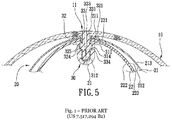
- Fig.1 is taken from the US 7,517,194 B2 and illustrates a known valve design used for many common types of sports balls.
- the ball comprises an outer hull 10 that has an opening 11.
- a valve 30 is attached to the outer hull 10 and comprises a housing 31 and a valve unit 33.
- the valve unit 33 is arranged in the opening 11 of the hull 10 and is hold in place by the valve body 31.
- the valve unit 33 comprises a channel 333 that is configured to receive an inflating needle (not shown) to fill the interior of an inflatable bladder 22 with gas such as air.
- an inflating needle is inserted into the valve unit 33 it widens the channel 333 such that the tip of the inflating needle can reach the interior of the inflatable bladder 22.
- the valve unit should close the channel gas-tight again such that no gas can leak from the interior of the inflatable bladder 22 through the channel 333 to the exterior.
- valve designs known form the prior art have several deficiencies. For example, to ensure gas-tight sealing some valve designs provide a strong pressure on the channel for the inflation needle and thereby exert a large friction on the inflation needle. As a consequence, it may be difficult to insert and remove the inflation needle. In some cases, this effect may even result in damage to the inflation needle, in particular during removal of the inflation needle from the valve.
- valve designs known form the prior art may suffer from gas leakage through the channel for the inflation needle and may easily wore out or even be irreversibly damaged by insertion of the inflation needle.
- the present invention provides a valve unit for a valve of an inflatable body, in particular a bladder for a sports ball, wherein the valve unit comprises a cavity containing a viscous, non-solid material, the cavity being adapted to be repeatedly penetrated by a gas injector, wherein the viscous, non-solid material is adapted to seal the valve unit against gas leakage when the gas injector is not penetrating the cavity.
- This embodiment ensures that the required gas-tight sealing function provided by the valve unit is supported by the viscous, non-solid material which provides superior sealing properties compared to the plastic and / or rubber material employed for this purpose by conventional valves.
- this embodiment allows to decouple the sealing function of the valve unit from its structural requirements and thus to optimize the valve design for inserting and removing a gas injector such as an inflation needle without adversely affecting the gas-tight sealing of the valve.
- a valve comprising a valve unit according to the above embodiment can be operated (e.g. insertion and removal of an inflation needle) more safely and conveniently without risking irreversibly damaging the valve during operation.
- the viscous non-solid material may comprise a gel and / or a silica gel. More specifically, the viscous, non-solid material may also comprise SiO 2 and Polyurethane. Such a viscous, non-solid material is easy to source and easy to process during manufacturing as well as nonhazardous in terms of health, environment and safety. However, other viscous materials of various compositions are possible as well.
- the viscous, non-solid material may exhibit a viscosity at a temperature of 25°C in the range of 5,000 cSt to 100,000 cSt, corresponding to a range of 0,005 m 2 /s to 0,1 m 2 /s in SI units.
- the cavity may comprise at least a first wall section that can be penetrated by the gas injector and which seals the cavity against a leakage of the viscous, non-solid material, when the gas injector is not penetrating the at least first wall section.
- the at least first wall section may be arranged in between the cavity and the exterior of the inflatable body.
- the first and / or the second wall section has a thickness of 0,25mm - 5mm, preferably 0,5mm - 4mm, more preferably 1mm - 3mm and most preferably between 1,5mm and 2,5mm.
- these embodiments ensure, that the viscous, non-solid material is well contained inside the cavity, in particular during operation of the valve.
- the valve unit is able to maintain its sealing properties over many duty cycles of operation.
- a first channel and / or a second channel may be arranged in the at least first wall section and / or the at least second wall section, wherein the at least first channel connects the cavity to the exterior of the inflatable body and / or the second channel connects the cavity to the interior of the inflatable body.
- the at least first wall section and the at least second wall section may be arranged on opposite sections of the cavity.
- an efficient and simple mechanism is provided to guide the gas injector form the exterior of the inflatable body through the valve unit and through the cavity that contains the viscous, non-solid material towards the interior of the inflatable body.
- the viscous, non-solid material is contained in a preconfigured pad, wherein the preconfigured pad may be coated with thermoplastic polyurethane, TPU.
- this embodiment facilitates mass production of the valve unit provided by the present invention, since the viscous, non-solid material can be produced and packed into the pad prior to assembly of the valve unit.
- the assembly process of the valve unit is less complex and can be optimized independently from the manufacturing of the pad that contains the viscous, non-solid material.
- the preconfigured pads may be already available form third-party suppliers and /or the manufacturing of the preconfigured pads may be performed by specialized manufacturers.
- the viscous, non-solid material is further adapted to moist the gas injector.
- valve unit may further enhance the operation of the valve unit, in particular if the gas injector is provided as an inflating needle, since the needle can then be more easily inserted and removed from the valve unit due to a reduced coefficient of friction.
- a further embodiment of the present invention relates to a valve for an inflatable body, in particular a bladder for a sports ball, that comprises a valve unit according any of the preceding embodiments.
- the resulting modular design of the valve facilitates the integration of a valve unit according to the present invention into already existing valve designs.
- valve unit For example, if the outer dimensions of the valve unit are adapted such that they correspond to already existing valve bodies that are used for inflatable bodies such as bladders for sports balls, the overall design of the valve body, the bladder and / or the sports ball can remain essentially unchanged. As a consequence, additional engineering efforts are avoided and a quick adaptation of the respective manufacturing processes and / or tools can be achieved.
- a further embodiment of the present invention is directed to an inflatable bladder, in particular a bladder for a sports ball that comprises a valve unit and / or a valve according to any of the preceding embodiments.
- a further embodiment of the present invention is directed to a ball, in particular a sports ball, comprising a valve unit, a valve and / or an inflatable bladder according to any of the preceding embodiments.
- a sports ball comprising an enhanced valve unit / valve / inflatable bladder as provided by the present invention can be more conveniently filled with air, while at the same time gas leakage and the risk to damage the valve by inserting the inflating needle is reduced. In this way, the comfort of use, the performance as well as the life-time of operation of the respective sports ball can be increased significantly.
- valve unit for a valve of an inflatable body a valve for a bladder of a sports ball.
- present invention is not limited to such a specific valve unit and application but could also be applied to other inflatable bodies, such as tire tubing, inflatable mattresses, leisure activity equipment, various types of protection gear, inflatable advertising equipment, and many more.
- Fig. 1 shows a valve design known form the prior art (i.e. the US 7,517,294 B2 ) for a sports ball and is described above in section 2, "Technical Background".
- Fig. 2 shows a cross-sectional view of a valve unit according to an embodiment of the present invention.
- the valve unit 200 may be rotational symmetric around a center axis and comprises a body 210 and an opening 230 that is adapted to receive a gas injector such as an inflation needle - a tool commonly used to inflate sports balls such as footballs and basket balls.
- the body 210 of the valve unit 200 may comprise various materials well-known in the art such as rubber, plastic, or similar materials and may be produced by conventional manufacturing methods such as injection molding or similar methods.
- the opening 230 is arranged on the top and essentially along the center axis of the valve unit 200.
- the valve unit 200 further comprises a portion of larger diameter 270 that may serve to mount the valve unit inside a valve body (see Fig. 3 ).
- a cavity 240 is arranged inside the lower portion of the body 210 of the valve unit 200.
- the cavity 240 comprises a viscous, non-solid material such as a gel (e.g. a silica gel comprising SiO 2 and polyurethane).
- a gel e.g. a silica gel comprising SiO 2 and polyurethane.
- Other viscous materials and in particular gels are also conceivable having at least the property to become compact again after removal of the inflating needle.
- the viscous, non-solid material may either be in direct contact with the inner walls of the cavity 440 or may be contained in a pack or pad.
- the viscous, non-solid material comprises a gel
- the gel may be contained in a gel pack which in turn comprises a surface layer such as a polymer coating for example comprising thermoplastic polyurethane (TPU) or any other polymer or plastic suitable for forming the surface coating of a gel pack.
- TPU thermoplastic polyurethane
- the surface coating should be configured such that it can be reliably be penetrated by a gas injector (see Fig. 4 ) that is used to inject gas into the interior of the respective inflatable body.
- the surface coating should be configured such, that the gel is reliably contained in the gel pack after the gas injector is removed again from the valve unit 200.
- valve unit 200 can be assembled without dedicated handling capabilities (machines, personnel, etc.) required for handling the viscous, non-solid material during assembly.
- preconfigured gel packs may even be sourced from specialized suppliers. In particular, it could be possible to use gel packs that are already available and have been designed for general, high volume applications.
- an upper section 250 of the cavity wall In between the lower end of opening 230 and the upper end of the cavity 240 there is an upper section 250 of the cavity wall. Said upper section 250 is configured such that it can also be penetrated by a gas injector such as an inflation needle.
- the upper section 250 of the cavity wall is adapted to be pierced by the respective gas injector when the valve is used the first time, whereas in other embodiments the upper section 250 is designed such that it comprises a centrally arranged channel (see Fig. 5 ) which may be used to guide the gas injector through the cavity 240 and can be spread apart when the gas injector is inserted into the valve unit 200 through the opening 230.
- the shape of the cavity 240 is essentially a cylinder.
- the height of the cavity H5 may be between 1mm and 20mm, preferably between 4mm and 16mm, more preferably between 6mm and 14mm and most preferably between 8mm and 12mm, and wherein the width W2 of the cavity may be between 0,5mm and 10mm, preferably between 0,75mm and 6mm, more preferably between 1mm and 4 mm and most preferably between 1,5mm and 3mm.
- the shape of the cavity 240 may also be essentially an ellipsoid, wherein the length of the semi-major axis is between 4mm and 16mm, preferably between 6mm and 14mm, more preferably between 8mm and 12mm and most preferably between 9mm and 11mm, and wherein the length of the semi-minor axis is between 0,5mm and 6mm, preferably between 0,75mm and 5mm, more preferably between 1mm and 4mm and most preferably between 1,5mm and 3mm.
- the cavity may have any geometrical shape and dimensions that are configured to be penetrated by a gas injector and to seal the valve unit gas-tight after the gas injector is removed again from the valve unit.
- the dimensions of the cavity in the plane perpendicular to the penetration direction of the gas injector may not be significantly smaller than the dimensions of the part of the gas injector that penetrates the cavity.
- the width W2 of the cavity 240 should be not much smaller than the maximal width of the gas injector or the maximal width of the section of the gas injector that penetrates the cavity.
- the height H5 of the cavity 240 should be large enough such that the gas-tight sealing of the valve can be reliably ensured.
- the cavity 240 is confined by a lower section 260 of the cavity wall which is also adapted to be penetrated by a gas injector.
- the lower section 260 of the cavity wall is adapted to be pierced by the respective gas injector when the valve unit 200 is used the first time, whereas in further embodiments the lower section 260 is designed such that it further comprises a centrally arranged channel (see Fig. 4 ) that is used to guide the gas injector towards the interior of the respective inflatable body and which may be spread apart when the gas injector is inserted into the valve unit 200.
- the upper section 250 of the cavity wall and / or the lower section 260 of the cavity wall may also contribute to the sealing function of the valve unit 200.
- the valve body 210 and / or the upper and / or the lower section of the cavity wall may comprise a material such as rubber or plastic that for example may also be used in conventional valve designs known from the prior art (see e.g. Fig. 1).
- valve unit 200 may also implement - at least in part - a similar sealing mechanism as valve designs known form the prior art (i.e. the upper 250 and lower 260 sections of the cavity wall do also contribute to sealing of the valve unit 200)
- valve unit 200 may be further enhanced, since the at least two different sealing mechanisms (i.e. sealing by a solid material and sealing by a viscous, non-solid material) may complement each other and / or may each compensate the respective weak points of the other.
- sealing mechanisms i.e. sealing by a solid material and sealing by a viscous, non-solid material
- the dimensions of the valve unit 200 are essentially given by: H1: 20mm, H2: 6mm H3: 4mm, H4: 2mm H5: 10mm, H6: 2mm W1: 15mm, W2: 2mm W3: 6mm
- valve unit may depend on the intended application of the valve unit (e.g. be determined by the size of the ball, the dimensions and / or type of the gas injector, the type of viscous material etc.).
- Fig. 3 shows a valve 300 that comprises the valve unit 200 from Fig. 2 . and a valve body 320.
- the portion of larger diameter 270 of the body 210 of the valve unit 200 is arranged in a recess of the valve body 320, such that the body 210 of the valve unit 200 is hold in position with respect to the valve body 320 when a gas injector such as an inflation needle is inserted into the valve 300.
- the valve body 320 may comprise the same material as the body 210 of the valve unit 200 or may also comprise a different material.
- the body 210 of the valve unit 200 may comprise a slightly softer material than the valve body 320.
- the body 210 may comprise rubber and the valve body 320 may comprise a molded polymer such as thermoplastic polyurethane or nylon or any other material known in the art.
- valve body 320 may be identically or similar to conventional valve bodies known from the art.
- novel valve unit shown in Fig. 2 may be readily integrated into existing valve bodies without significant changes to the design and / or manufacturing process of the respective valve.
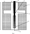
- Fig. 4 depicts the valve 300 of Fig. 3 comprising the valve unit 200 of Fig. 2 during operation i.e. while being used to fill an inflatable body with gas.
- an inflation needle 450 is shown, that completely penetrates the valve unit 210 which is hold in place by the valve body 320.
- the tip 460 of the inflation needle 450 protrudes from the lower section of the wall of the cavity 240 into the interior of the inflatable body (not shown).
- the opening 230 of the valve unit 200 is configured to receive the inflation needle 450 and / or guide it along a central axis of the valve 300.
- the inflation needle 450 thus penetrates the cavity 240 essentially along the central axis of the cavity.
- the minimal distance between the gas injector 450 and the walls of the cavity 240 i.e. the space that is filled with the viscous, non-solid material
- the viscous, non-solid material that is contained inside the cavity 240 is adapted to seal the valve unit 200 gas-tight during all states of operation of the valve 300 i.e. prior to insertion of the inflation needle 450, while the inflation needle 450 is penetrating the cavity 240 and after the inflation needle 450 has been removed from the valve 300.
- the composition of the viscous, non-solid material inside the cavity 240 may be chosen such that the viscosity of the viscous, non-solid material is high enough such that the viscous, non-solid material does not leak out of the cavity 240 of the valve 300, but at the same time low enough to facilitate penetration by the inflation needle 450.
- the viscosity should also be low enough to ensure that the viscous, non-solid material relaxes back (e.g. flows back) fast enough into its original configuration, in order to ensure immediate or near-immediate gas-tight sealing of the valve unit 200 after the inflation needle 450 is removed from the valve 300.
- the viscous, non-solid material may comprise a gel, such as a xerogel or hydrogel and in particular a silica gel and / or a gel comprising SiO 2 and polyurethane.
- such gel may be heat resistant up to a certain temperature e.g. 300°C thereby rendering the sealing mechanism provided by the invention essentially unaffected by the heat caused by friction when inserting the gas injector or inflation needle into the valve unit.
- the viscous, non-solid material essentially decouples the sealing function of the valve 300 from its mechanical requirements (i.e. to house the valve unit 200, to attach the valve 300 to the respective inflatable body, to receive and guide the gas injector 450 etc.). Consequently, both functions can be optimized independently and thus, overall valve performance can be increased significantly.
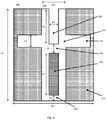
- Fig. 5 illustrates another embodiment of a valve 300 according to the present invention.
- the body 210 of the valve unit 200 comprises a first 555 and a second channel 565 that extend through the upper and the lower wall section of the cavity 240.
- Said channels are configured to receive and guide the tip of a gas injector such as the tip of an inflation needle (see Fig. 4 ) through the cavity 240 and towards the interior of the respective inflatable body.
- the channels 555, 565 are created during manufacturing of the body 210 of the valve unit 200. In other embodiments, the channels 555, 565 are created when the inflation needle is inserted into the valve unit 200 for the first time and the tip of the inflation needle punctures the upper and the lower wall of the cavity 240 while penetrating the valve unit 200.
- Providing the channels 555, 565 already during manufacturing facilitates using the valve 300 for the first time and may reduce the risk of damaging the valve unit by inserting the inflation needle.
- Fig. 6 depicts another valve design for an inflatable body 610 according to an embodiment of the present invention.
- a valve 300 as illustrated in Figs. 3 - 5 it is also possible to design the valve such that it essentially comprises a pad 620 that contains a viscous, non-solid material and that comprises an outer surface layer that is adapted to be penetrated by a gas injector 620 such as an inflation needle.
- the pad 620 may be arranged on the inside of an inflatable body 610 such as a bladder of a sports ball.
- the pad 620 is further arranged such that it covers an opening in the hull of the inflatable body 610 and is configured such that the opening is sealed gas-tight when the gas injector 620 is not penetrating the opening and the pad 620 containing the viscous, non-solid material.
- the viscous, non-solid material may comprise a gel and the pad 620 may be a gel pack.
- This embodiment of the present invention may be particularly useful for applications for which a low weight of the valve, low production costs and ease of manufacture is critical.
Landscapes
- Engineering & Computer Science (AREA)
- General Engineering & Computer Science (AREA)
- Mechanical Engineering (AREA)
- Health & Medical Sciences (AREA)
- General Health & Medical Sciences (AREA)
- Physical Education & Sports Medicine (AREA)
- Check Valves (AREA)
Abstract
Description
- The present invention relates to a valve unit for a valve of an inflatable body such as a bladder for a sports ball as well as to a valve, an inflatable bladder and a sports ball.
- Inflatable bodies have a multitude of applications in modern manufacturing goods such as ball bladders, tire tubing, leisure activity equipment, floating devices, safety gear and many more. Mainly, this is due to superior cushioning and deformation properties as well as the capability to reversibly change the volume of the inflatable body by inflating or deflating the inflatable body.
- A common feature of inflatable bodies is a valve that can be used to repeatedly fill the interior of the respective inflatable body with a certain type of gas such as air and that is configured to seal the interior of the respective inflatable body gas-tight.
- Designing valves for inflatable bodies in such a way that the valve is easy to manufacture and to operate, long-lived and reliably gas-tight has remained a perpetual engineering task. In particular designing valves for bladders of sports balls such as footballs, basket balls and volley balls has remained challenging due to further requirements that need to be fulfilled by the respective valve such as a small footprint and low weight as well as an often desired smooth surface of the respective sports ball.
- Fig.1 is taken from the
US 7,517,194 B2 and illustrates a known valve design used for many common types of sports balls. The ball comprises anouter hull 10 that has anopening 11. Avalve 30 is attached to theouter hull 10 and comprises ahousing 31 and a valve unit 33. The valve unit 33 is arranged in theopening 11 of thehull 10 and is hold in place by thevalve body 31. The valve unit 33 comprises achannel 333 that is configured to receive an inflating needle (not shown) to fill the interior of aninflatable bladder 22 with gas such as air. When the inflating needle is inserted into the valve unit 33 it widens thechannel 333 such that the tip of the inflating needle can reach the interior of theinflatable bladder 22. After the inflating needle has been removed from thechannel 333 the valve unit should close the channel gas-tight again such that no gas can leak from the interior of theinflatable bladder 22 through thechannel 333 to the exterior. - Similar and related valve designs are well-known from the prior art for example from the
EP 2 18 92 66 B1 , theEP 00 13 434 B1 , theJPH11244421A WO 2016 013210A1 . - However, the valve designs known form the prior art have several deficiencies. For example, to ensure gas-tight sealing some valve designs provide a strong pressure on the channel for the inflation needle and thereby exert a large friction on the inflation needle. As a consequence, it may be difficult to insert and remove the inflation needle. In some cases, this effect may even result in damage to the inflation needle, in particular during removal of the inflation needle from the valve.
- In addition, some valve designs known form the prior art may suffer from gas leakage through the channel for the inflation needle and may easily wore out or even be irreversibly damaged by insertion of the inflation needle.
- Thus, there remains a strong interest in a novel gas-tight valve design that is easy to operate, is less prone to be damaged by insertion of an inflation needle and remains operational over many duty cycles. Moreover, such valve design should be simple to manufacture at low cost.
- The above-mentioned problems are at least partly solved by the subject matter of the independent claims of the present application. Embodiments of the invention are described in the depended claims.
- In one embodiment, the present invention provides a valve unit for a valve of an inflatable body, in particular a bladder for a sports ball, wherein the valve unit comprises a cavity containing a viscous, non-solid material, the cavity being adapted to be repeatedly penetrated by a gas injector, wherein the viscous, non-solid material is adapted to seal the valve unit against gas leakage when the gas injector is not penetrating the cavity.
- This embodiment ensures that the required gas-tight sealing function provided by the valve unit is supported by the viscous, non-solid material which provides superior sealing properties compared to the plastic and / or rubber material employed for this purpose by conventional valves.
- Moreover, this embodiment allows to decouple the sealing function of the valve unit from its structural requirements and thus to optimize the valve design for inserting and removing a gas injector such as an inflation needle without adversely affecting the gas-tight sealing of the valve.
- As a consequence, a valve comprising a valve unit according to the above embodiment can be operated (e.g. insertion and removal of an inflation needle) more safely and conveniently without risking irreversibly damaging the valve during operation.
- The viscous non-solid material may comprise a gel and / or a silica gel. More specifically, the viscous, non-solid material may also comprise SiO2 and Polyurethane. Such a viscous, non-solid material is easy to source and easy to process during manufacturing as well as nonhazardous in terms of health, environment and safety. However, other viscous materials of various compositions are possible as well.
- Further, the viscous, non-solid material may exhibit a viscosity at a temperature of 25°C in the range of 5,000 cSt to 100,000 cSt, corresponding to a range of 0,005 m2/s to 0,1 m2/s in SI units.
- Such material ensures ease of penetration of the gas injector as well as fast and reliable gas tight sealing after the gas injector has been removed from the valve unit.
- Further, the cavity may comprise at least a first wall section that can be penetrated by the gas injector and which seals the cavity against a leakage of the viscous, non-solid material, when the gas injector is not penetrating the at least first wall section.
- Moreover, the at least first wall section may be arranged in between the cavity and the exterior of the inflatable body. There may also be a second wall section that is arranged in between the cavity and the interior of the inflatable body.
- In some embodiments the first and / or the second wall section has a thickness of 0,25mm - 5mm, preferably 0,5mm - 4mm, more preferably 1mm - 3mm and most preferably between 1,5mm and 2,5mm.
- For example, these embodiments ensure, that the viscous, non-solid material is well contained inside the cavity, in particular during operation of the valve. As a consequence, the valve unit is able to maintain its sealing properties over many duty cycles of operation.
- A first channel and / or a second channel may be arranged in the at least first wall section and / or the at least second wall section, wherein the at least first channel connects the cavity to the exterior of the inflatable body and / or the second channel connects the cavity to the interior of the inflatable body. In particular, the at least first wall section and the at least second wall section may be arranged on opposite sections of the cavity.
- For instance, in this way an efficient and simple mechanism is provided to guide the gas injector form the exterior of the inflatable body through the valve unit and through the cavity that contains the viscous, non-solid material towards the interior of the inflatable body.
- In particular, it can thus be ensured, that the gas injector penetrates the cavity essentially along the center line of the valve unit. As a consequence, gas-tight sealing is enhanced and the risk to damage the valve unit reduced significantly.
- In a further embodiment of the present invention, the viscous, non-solid material is contained in a preconfigured pad, wherein the preconfigured pad may be coated with thermoplastic polyurethane, TPU.
- For example, this embodiment facilitates mass production of the valve unit provided by the present invention, since the viscous, non-solid material can be produced and packed into the pad prior to assembly of the valve unit.
- Consequently, the assembly process of the valve unit is less complex and can be optimized independently from the manufacturing of the pad that contains the viscous, non-solid material. Moreover, the preconfigured pads may be already available form third-party suppliers and /or the manufacturing of the preconfigured pads may be performed by specialized manufacturers.
- In a further embodiment of the present invention, the viscous, non-solid material is further adapted to moist the gas injector.
- This may further enhance the operation of the valve unit, in particular if the gas injector is provided as an inflating needle, since the needle can then be more easily inserted and removed from the valve unit due to a reduced coefficient of friction.
- A further embodiment of the present invention relates to a valve for an inflatable body, in particular a bladder for a sports ball, that comprises a valve unit according any of the preceding embodiments. The resulting modular design of the valve facilitates the integration of a valve unit according to the present invention into already existing valve designs.
- For example, if the outer dimensions of the valve unit are adapted such that they correspond to already existing valve bodies that are used for inflatable bodies such as bladders for sports balls, the overall design of the valve body, the bladder and / or the sports ball can remain essentially unchanged. As a consequence, additional engineering efforts are avoided and a quick adaptation of the respective manufacturing processes and / or tools can be achieved.
- A further embodiment of the present invention is directed to an inflatable bladder, in particular a bladder for a sports ball that comprises a valve unit and / or a valve according to any of the preceding embodiments.
- A further embodiment of the present invention is directed to a ball, in particular a sports ball, comprising a valve unit, a valve and / or an inflatable bladder according to any of the preceding embodiments.
- For example, a sports ball comprising an enhanced valve unit / valve / inflatable bladder as provided by the present invention can be more conveniently filled with air, while at the same time gas leakage and the risk to damage the valve by inserting the inflating needle is reduced. In this way, the comfort of use, the performance as well as the life-time of operation of the respective sports ball can be increased significantly.
- Aspects of the present invention are described in more detail in the following by reference to the accompanying figures. These figures show:
- Fig. 1:
- cross-sectional view of a valve for ball bladders known form the prior art (
US7,517,294B2 ); - Fig. 2:
- cross-sectional view of a valve unit according to an embodiment of the present invention;
- Fig. 3:
- cross-sectional view of a valve according to another embodiment of the present invention;
- Fig. 4:
- cross-sectional view of a valve during operation according to an embodiment of the present invention
- Fig. 5:
- cross-sectional view of a valve according to a further embodiment of the present invention
- Fig. 6:
- cross-sectional view of an inflatable body according to a further embodiment of the present invention
- In the following, exemplary embodiments of the present invention of valve unit for a valve of an inflatable body are illustrated referring to a valve for a bladder of a sports ball. However, it is to be understood that the present invention is not limited to such a specific valve unit and application but could also be applied to other inflatable bodies, such as tire tubing, inflatable mattresses, leisure activity equipment, various types of protection gear, inflatable advertising equipment, and many more.
- Moreover, while specific feature combinations are described in the following with respect to certain embodiments of the present invention, it is to be understood that the disclosure is not limited to such embodiments. In other words, not all the described features have to be present for realizing the invention and the embodiments may be modified by combining certain features of one embodiment with one or more features of another embodiment.
- Fig. 1 shows a valve design known form the prior art (i.e. the
US 7,517,294 B2 ) for a sports ball and is described above in section 2, "Technical Background". -
Fig. 2 shows a cross-sectional view of a valve unit according to an embodiment of the present invention. Thevalve unit 200 may be rotational symmetric around a center axis and comprises abody 210 and anopening 230 that is adapted to receive a gas injector such as an inflation needle - a tool commonly used to inflate sports balls such as footballs and basket balls. Thebody 210 of thevalve unit 200 may comprise various materials well-known in the art such as rubber, plastic, or similar materials and may be produced by conventional manufacturing methods such as injection molding or similar methods. - For the illustrated embodiment, the
opening 230 is arranged on the top and essentially along the center axis of thevalve unit 200. Thevalve unit 200 further comprises a portion oflarger diameter 270 that may serve to mount the valve unit inside a valve body (seeFig. 3 ). - A
cavity 240 is arranged inside the lower portion of thebody 210 of thevalve unit 200. Thecavity 240 comprises a viscous, non-solid material such as a gel (e.g. a silica gel comprising SiO2 and polyurethane). Other viscous materials and in particular gels are also conceivable having at least the property to become compact again after removal of the inflating needle. - The viscous, non-solid material may either be in direct contact with the inner walls of the cavity 440 or may be contained in a pack or pad. For example, if the viscous, non-solid material comprises a gel, the gel may be contained in a gel pack which in turn comprises a surface layer such as a polymer coating for example comprising thermoplastic polyurethane (TPU) or any other polymer or plastic suitable for forming the surface coating of a gel pack.
- In particular, the surface coating should be configured such that it can be reliably be penetrated by a gas injector (see
Fig. 4 ) that is used to inject gas into the interior of the respective inflatable body. Moreover, the surface coating should be configured such, that the gel is reliably contained in the gel pack after the gas injector is removed again from thevalve unit 200. - Providing the viscous, non-solid material inside a dedicated / preconfigured pack or pad offers the advantage that the
valve unit 200 can be assembled without dedicated handling capabilities (machines, personnel, etc.) required for handling the viscous, non-solid material during assembly. For example, preconfigured gel packs may even be sourced from specialized suppliers. In particular, it could be possible to use gel packs that are already available and have been designed for general, high volume applications. - In between the lower end of
opening 230 and the upper end of thecavity 240 there is anupper section 250 of the cavity wall. Saidupper section 250 is configured such that it can also be penetrated by a gas injector such as an inflation needle. In some embodiments of the present invention theupper section 250 of the cavity wall is adapted to be pierced by the respective gas injector when the valve is used the first time, whereas in other embodiments theupper section 250 is designed such that it comprises a centrally arranged channel (seeFig. 5 ) which may be used to guide the gas injector through thecavity 240 and can be spread apart when the gas injector is inserted into thevalve unit 200 through theopening 230. - In some embodiments, the shape of the
cavity 240 is essentially a cylinder. The height of the cavity H5 may be between 1mm and 20mm, preferably between 4mm and 16mm, more preferably between 6mm and 14mm and most preferably between 8mm and 12mm, and wherein the width W2 of the cavity may be between 0,5mm and 10mm, preferably between 0,75mm and 6mm, more preferably between 1mm and 4 mm and most preferably between 1,5mm and 3mm. - In other embodiments the shape of the
cavity 240 may also be essentially an ellipsoid, wherein the length of the semi-major axis is between 4mm and 16mm, preferably between 6mm and 14mm, more preferably between 8mm and 12mm and most preferably between 9mm and 11mm, and wherein the length of the semi-minor axis is between 0,5mm and 6mm, preferably between 0,75mm and 5mm, more preferably between 1mm and 4mm and most preferably between 1,5mm and 3mm. - However, the cavity may have any geometrical shape and dimensions that are configured to be penetrated by a gas injector and to seal the valve unit gas-tight after the gas injector is removed again from the valve unit.
- In particular, the dimensions of the cavity in the plane perpendicular to the penetration direction of the gas injector (e.g. the plane perpendicular to the central axis of the valve unit) may not be significantly smaller than the dimensions of the part of the gas injector that penetrates the cavity. For example, the width W2 of the
cavity 240 should be not much smaller than the maximal width of the gas injector or the maximal width of the section of the gas injector that penetrates the cavity. - Further, the height H5 of the
cavity 240 should be large enough such that the gas-tight sealing of the valve can be reliably ensured. - At the lower end of the
valve unit 200, thecavity 240 is confined by alower section 260 of the cavity wall which is also adapted to be penetrated by a gas injector. In some embodiments of the present invention thelower section 260 of the cavity wall is adapted to be pierced by the respective gas injector when thevalve unit 200 is used the first time, whereas in further embodiments thelower section 260 is designed such that it further comprises a centrally arranged channel (seeFig. 4 ) that is used to guide the gas injector towards the interior of the respective inflatable body and which may be spread apart when the gas injector is inserted into thevalve unit 200. - The
upper section 250 of the cavity wall and / or thelower section 260 of the cavity wall may also contribute to the sealing function of thevalve unit 200. In particular, thevalve body 210 and / or the upper and / or the lower section of the cavity wall may comprise a material such as rubber or plastic that for example may also be used in conventional valve designs known from the prior art (see e.g. Fig. 1). - Thus, supplementary to the sealing function provided by the viscous, non-solid material contained in the
cavity 240 thevalve unit 200 may also implement - at least in part - a similar sealing mechanism as valve designs known form the prior art (i.e. the upper 250 and lower 260 sections of the cavity wall do also contribute to sealing of the valve unit 200) - Consequently, the overall performance of the
valve unit 200 may be further enhanced, since the at least two different sealing mechanisms (i.e. sealing by a solid material and sealing by a viscous, non-solid material) may complement each other and / or may each compensate the respective weak points of the other. - In one embodiment, the dimensions of the
valve unit 200 are essentially given by:H1: 20mm, H2: 6mm H3: 4mm, H4: 2mm H5: 10mm, H6: 2mm W1: 15mm, W2: 2mm W3: 6mm - These dimensions are given to illustrate the overall dimensions of a specific embodiment of the present invention. It should be noted however, that some or all dimensions of other embodiments may be different from the ones given above and the dimensions of the valve unit may depend on the intended application of the valve unit (e.g. be determined by the size of the ball, the dimensions and / or type of the gas injector, the type of viscous material etc.).
-
Fig. 3 shows avalve 300 that comprises thevalve unit 200 fromFig. 2 . and avalve body 320. The portion oflarger diameter 270 of thebody 210 of thevalve unit 200 is arranged in a recess of thevalve body 320, such that thebody 210 of thevalve unit 200 is hold in position with respect to thevalve body 320 when a gas injector such as an inflation needle is inserted into thevalve 300. Thevalve body 320 may comprise the same material as thebody 210 of thevalve unit 200 or may also comprise a different material. - In particular, the
body 210 of thevalve unit 200 may comprise a slightly softer material than thevalve body 320. For example, thebody 210 may comprise rubber and thevalve body 320 may comprise a molded polymer such as thermoplastic polyurethane or nylon or any other material known in the art. - Moreover, the dimensions and the material of the
valve body 320 may be identically or similar to conventional valve bodies known from the art. In particular, the novel valve unit shown inFig. 2 may be readily integrated into existing valve bodies without significant changes to the design and / or manufacturing process of the respective valve. -
Fig. 4 depicts thevalve 300 ofFig. 3 comprising thevalve unit 200 ofFig. 2 during operation i.e. while being used to fill an inflatable body with gas.
In addition to the structural elements described above (200, 300, 210, 320, 230 240) aninflation needle 450 is shown, that completely penetrates thevalve unit 210 which is hold in place by thevalve body 320. Thetip 460 of theinflation needle 450 protrudes from the lower section of the wall of thecavity 240 into the interior of the inflatable body (not shown). - The
opening 230 of thevalve unit 200 is configured to receive theinflation needle 450 and / or guide it along a central axis of thevalve 300. In some embodiments, theinflation needle 450 thus penetrates thecavity 240 essentially along the central axis of the cavity. - In this way, the minimal distance between the
gas injector 450 and the walls of the cavity 240 (i.e. the space that is filled with the viscous, non-solid material) is maximized. - The viscous, non-solid material that is contained inside the
cavity 240 is adapted to seal thevalve unit 200 gas-tight during all states of operation of thevalve 300 i.e. prior to insertion of theinflation needle 450, while theinflation needle 450 is penetrating thecavity 240 and after theinflation needle 450 has been removed from thevalve 300. - The composition of the viscous, non-solid material inside the
cavity 240 may be chosen such that the viscosity of the viscous, non-solid material is high enough such that the viscous, non-solid material does not leak out of thecavity 240 of thevalve 300, but at the same time low enough to facilitate penetration by theinflation needle 450. The viscosity should also be low enough to ensure that the viscous, non-solid material relaxes back (e.g. flows back) fast enough into its original configuration, in order to ensure immediate or near-immediate gas-tight sealing of thevalve unit 200 after theinflation needle 450 is removed from thevalve 300. For example, the viscous, non-solid material may comprise a gel, such as a xerogel or hydrogel and in particular a silica gel and / or a gel comprising SiO2 and polyurethane. - In particular, such gel may be heat resistant up to a certain temperature e.g. 300°C thereby rendering the sealing mechanism provided by the invention essentially unaffected by the heat caused by friction when inserting the gas injector or inflation needle into the valve unit.
- As can be seen from the illustration of the
valve 300 during operation, the viscous, non-solid material essentially decouples the sealing function of thevalve 300 from its mechanical requirements (i.e. to house thevalve unit 200, to attach thevalve 300 to the respective inflatable body, to receive and guide thegas injector 450 etc.). Consequently, both functions can be optimized independently and thus, overall valve performance can be increased significantly. -
Fig. 5 illustrates another embodiment of avalve 300 according to the present invention. In addition to the structural elements shown inFig. 3 andFig. 4 thebody 210 of thevalve unit 200 comprises a first 555 and asecond channel 565 that extend through the upper and the lower wall section of thecavity 240. Said channels are configured to receive and guide the tip of a gas injector such as the tip of an inflation needle (seeFig. 4 ) through thecavity 240 and towards the interior of the respective inflatable body. - In some embodiments, the
channels body 210 of thevalve unit 200. In other embodiments, thechannels valve unit 200 for the first time and the tip of the inflation needle punctures the upper and the lower wall of thecavity 240 while penetrating thevalve unit 200. - Providing the
channels valve 300 for the first time and may reduce the risk of damaging the valve unit by inserting the inflation needle. -
Fig. 6 depicts another valve design for aninflatable body 610 according to an embodiment of the present invention. Instead of avalve 300 as illustrated inFigs. 3 - 5 it is also possible to design the valve such that it essentially comprises apad 620 that contains a viscous, non-solid material and that comprises an outer surface layer that is adapted to be penetrated by agas injector 620 such as an inflation needle. - The
pad 620 may be arranged on the inside of aninflatable body 610 such as a bladder of a sports ball. Thepad 620 is further arranged such that it covers an opening in the hull of theinflatable body 610 and is configured such that the opening is sealed gas-tight when thegas injector 620 is not penetrating the opening and thepad 620 containing the viscous, non-solid material. - As described above with reference to
Fig. 2 the viscous, non-solid material may comprise a gel and thepad 620 may be a gel pack. This embodiment of the present invention may be particularly useful for applications for which a low weight of the valve, low production costs and ease of manufacture is critical. - In the following, further embodiments are described to facilitate the understanding of the invention:
- 1. Valve unit (200) for a valve (300) of an inflatable body, in particular a bladder for a sports ball, the valve unit (200) comprising:
- a. a cavity (240) containing a viscous, non-solid material, the cavity (240) being adapted to be repeatedly penetrated by a gas injector (450),
- b. wherein the viscous, non-solid material is adapted to seal the valve unit (200) against gas leakage when the gas injector (450) is not penetrating the cavity (240).
- 2. Valve unit (200) according to embodiment 1,
wherein the viscous, non-solid material comprises a gel. - 3. Valve unit (200) according to embodiment 2, wherein the gel comprises a silica gel.
- 4. A valve unit (200) according to any of the preceding embodiments,
wherein the viscous, non-solid material comprises SiO2 and Polyurethane. - 5. A valve unit (200) according to any of the preceding embodiments, wherein the viscous, non-solid material exhibits a viscosity at a temperature of 25°C in the range of 5,000 cSt to 100,000 cSt.
- 6. Valve unit (200) according to any of the preceding embodiments, wherein the cavity (240) comprises at least a first wall section (250) that can be penetrated by the gas injector (450) and which seals the cavity (240) against a leakage of the viscous, non-solid material, when the gas injector (450) is not penetrating the at least first wall section (250).
- 7. Valve unit (200) according to the preceding embodiment, wherein the at least first wall section (250) is arranged in between the cavity (240) and the exterior of the inflatable body.
- 8. Valve unit (200) according to the preceding embodiments wherein an at least second wall section (260) is arranged in between the cavity (240) and the interior of the inflatable body.
- 9. Valve unit (200) according to any of the preceding embodiments 6 - 8, wherein the first (250) and / or the second wall section (260) has a thickness of 0,25 mm - 5 mm, preferably 0,5mm - 4 mm, more preferably 1 mm - 3 mm and most preferably between 1,5 mm and 2,5 mm.
- 10. Valve unit (200) according to any of the preceding embodiments 7 - 9,
wherein a first channel (555) and / or a second channel (565) is arranged in the at least first wall section (250) and / or the at least second wall section (260), wherein the at least first channel (555) connects the cavity (240) to the exterior of the inflatable body and / or the second channel (565) connects the cavity (240) to the interior of the inflatable body. - 11. Valve unit (200) according to embodiments 8 - 10, wherein the at least first wall section (250) and the at least second wall section (260) are arranged on opposite sections of the cavity (240).
- 12. Valve unit (200) according to any of the preceding embodiments, wherein the height (H5) of the cavity (240) is between 1mm and 20mm, preferably between 4mm and 16mm, more preferably between 6mm and 14mm and most preferably between 8mm and 12mm, and wherein the width (W2) of the cavity is between 0,5mm and 10mm, preferably between 0,75mm and 6mm, more preferably between 1mm and 4 mm and most preferably between 1,5mm and 3mm.
- 13. Valve unit (200) according to any of the preceding embodiments,
wherein the viscous, non-solid material is contained in a preconfigured pad. - 14. Valve unit (200) according to the preceding embodiment 13,
wherein the preconfigured pad is coated with thermoplastic polyurethane, TPU. - 15. Valve unit (200) according to any of the preceding embodiments,
wherein the viscous, non-solid material is further adapted to moist the gas injector (450). - 16. Valve unit (200) according to any of the preceding embodiments,
wherein the cavity (240) containing the viscous, non-solid material is adapted to be repeatedly penetrated by a gas injector (450) provided as an inflating needle. - 17. Valve (300) for an inflatable body in particular a bladder for a sports ball, comprising a valve body (320) adapted to house a valve unit (200) according to any of the preceding embodiments.
- 18. Inflatable bladder (610), in particular a bladder for a sports ball comprising a valve (300) according to embodiment 17 or a valve unit (200) according to the embodiments 1 - 16.
- 19. Ball, in particular a sports ball, comprising a valve unit (200), a valve (300) and / or an inflatable bladder (610) according to any of the preceding embodiments.
Claims (15)
- Valve unit (200) for a valve (300) of an inflatable body, in particular a bladder for a sports ball, the valve unit (200) comprising:a. a cavity (240) containing a viscous, non-solid material, the cavity (240) being adapted to be repeatedly penetrated by a gas injector (450),b. wherein the viscous, non-solid material is adapted to seal the valve unit (200) against gas leakage when the gas injector (450) is not penetrating the cavity (240).
- Valve unit (200) according to claim 1,
wherein the viscous, non-solid material comprises a gel. - A valve unit (200) according to any of the preceding claims, wherein the viscous, non-solid material exhibits a viscosity at a temperature of 25°C in the range of 5,000 cSt to 100,000 cSt.
- Valve unit (200) according to any of the preceding claims, wherein the cavity (240) comprises at least a first wall section (250) that can be penetrated by the gas injector (450) and which seals the cavity (240) against a leakage of the viscous, non-solid material, when the gas injector (450) is not penetrating the at least first wall section (250).
- Valve unit (200) according to the preceding claim, wherein the at least first wall section (250) is arranged in between the cavity (240) and the exterior of the inflatable body.
- Valve unit (200) according to the preceding claims wherein an at least second wall section (260) is arranged in between the cavity (240) and the interior of the inflatable body.
- Valve unit (200) according to any of the preceding claims 4 - 6, wherein the first (250) and / or the second wall section (260) has a thickness of 0,25 mm - 5 mm, preferably 0,5mm - 4 mm, more preferably 1 mm - 3 mm and most preferably between 1,5 mm and 2,5 mm.
- Valve unit (200) according to any of the preceding claims 5 - 7,
wherein a first channel (555) and / or a second channel (565) is arranged in the at least first wall section (250) and / or the at least second wall section (260), wherein the at least first channel (555) connects the cavity (240) to the exterior of the inflatable body and / or the second channel (565) connects the cavity (240) to the interior of the inflatable body. - Valve unit (200) according to any of the preceding claims, wherein the height (H5) of the cavity (240) is between 1mm and 20mm, preferably between 4mm and 16mm, more preferably between 6mm and 14mm and most preferably between 8mm and 12mm, and wherein the width (W2) of the cavity is between 0,5mm and 10mm, preferably between 0,75mm and 6mm, more preferably between 1mm and 4 mm and most preferably between 1,5mm and 3mm.
- Valve unit (200) according to any of the preceding claims,
wherein the viscous, non-solid material is contained in a preconfigured pad. - Valve unit (200) according to any of the preceding claims,
wherein the viscous, non-solid material is further adapted to moist the gas injector (450). - Valve unit (200) according to any of the preceding claims,
wherein the cavity (240) containing the viscous, non-solid material is adapted to be repeatedly penetrated by a gas injector (450) provided as an inflating needle. - Valve (300) for an inflatable body in particular a bladder for a sports ball, comprising a valve body (320) adapted to house a valve unit (200) according to any of the preceding claims.
- Inflatable bladder (610), in particular a bladder for a sports ball comprising a valve (300) according to claim 13 or a valve unit (200) according to the claims 1 - 12.
- Ball, in particular a sports ball, comprising a valve unit (200), a valve (300) and / or an inflatable bladder (610) according to any of the preceding claims.
Applications Claiming Priority (1)
| Application Number | Priority Date | Filing Date | Title |
|---|---|---|---|
| DE102018205119.4A DE102018205119A1 (en) | 2018-04-05 | 2018-04-05 | Valve unit for a valve of an inflatable body |
Publications (2)
| Publication Number | Publication Date |
|---|---|
| EP3549644A1 true EP3549644A1 (en) | 2019-10-09 |
| EP3549644B1 EP3549644B1 (en) | 2020-12-09 |
Family
ID=65493928
Family Applications (1)
| Application Number | Title | Priority Date | Filing Date |
|---|---|---|---|
| EP19157774.1A Active EP3549644B1 (en) | 2018-04-05 | 2019-02-18 | Valve unit for a valve of an inflatable body |
Country Status (3)
| Country | Link |
|---|---|
| US (1) | US20190309864A1 (en) |
| EP (1) | EP3549644B1 (en) |
| DE (1) | DE102018205119A1 (en) |
Families Citing this family (4)
| Publication number | Priority date | Publication date | Assignee | Title |
|---|---|---|---|---|
| GB2588756B (en) * | 2019-10-25 | 2022-08-31 | Grays Of Cambridge Int Ltd | Valve system |
| US20230213106A1 (en) * | 2022-01-05 | 2023-07-06 | Belgravia Wood Limited | Air valve, inflation, and deflation apparatuses and methods |
| CN114336348B (en) * | 2022-01-06 | 2024-09-03 | 深圳市中吉电气科技有限公司 | Humidity relay protector for transformer box |
| US12285655B2 (en) * | 2024-10-14 | 2025-04-29 | Shenzhen Jiaxin Technology Co., Ltd. | Luminous ball |
Citations (8)
| Publication number | Priority date | Publication date | Assignee | Title |
|---|---|---|---|---|
| US2183900A (en) * | 1938-01-10 | 1939-12-19 | William J Voit | Inflation valve |
| EP0013434B1 (en) | 1978-12-29 | 1982-12-08 | Mizuno Corporation | Inflatable ball |
| JPH11244421A (en) | 1998-03-04 | 1999-09-14 | Mizuno Corp | Ball game ball and hermetic plug with hermetic plug attached to air injection valve |
| US7517294B2 (en) | 2007-02-02 | 2009-04-14 | Tsai I-Chen | Dual-bladder inflatable ball |
| US7517194B2 (en) | 2006-04-30 | 2009-04-14 | General Electric Company | Rotor blade for a wind turbine |
| US20090118756A1 (en) * | 2005-06-01 | 2009-05-07 | Nicolas Francois Michel Valencon | Intra-gastric balloon provided with a gel-containing valve, kit and use thereof |
| WO2016013210A1 (en) | 2014-07-23 | 2016-01-28 | 株式会社モルテン | Ball and method for producing same |
| EP2189266B1 (en) | 2008-11-25 | 2016-03-23 | adidas International Marketing B.V. | Valve for a ball and method of manufacture of a valve for a ball |
Family Cites Families (27)
| Publication number | Priority date | Publication date | Assignee | Title |
|---|---|---|---|---|
| US2934344A (en) * | 1954-05-12 | 1960-04-26 | Barr Rubber Products Company | Valve for inflatable object |
| US3600718A (en) * | 1969-12-29 | 1971-08-24 | Dow Corning | Inflatable prosthesis |
| US3919724A (en) * | 1974-06-07 | 1975-11-18 | Medical Eng Corp | Implantable prosthesis having a self-sealing valve |
| US4263682A (en) * | 1978-09-01 | 1981-04-28 | Dow Corning Corporation | Self-sealing valve and fluid fillable article including such a valve |
| US4253201A (en) * | 1979-05-24 | 1981-03-03 | Ross David A | Prosthesis with self-sealing valve |
| JPS5751797A (en) * | 1980-09-12 | 1982-03-26 | Janome Sewing Mach Co Ltd | Grease composition |
| US4332634A (en) * | 1981-01-14 | 1982-06-01 | Medical Engineering Corporation | Method of preparing a resealable valve |
| US4568081A (en) * | 1983-04-13 | 1986-02-04 | Wilson Sporting Goods Company | Inflation needle lubricating plug insert-type valve assembly |
| US5033498A (en) * | 1990-06-08 | 1991-07-23 | The Schlueter Company | Valve for inflated article |
| US5246114A (en) * | 1991-08-12 | 1993-09-21 | Underwood John P | Preserving package and method of storage |
| JP3145441B2 (en) * | 1991-10-24 | 2001-03-12 | 日本パーカライジング株式会社 | Lubricant paint |
| US5507808A (en) * | 1994-10-26 | 1996-04-16 | Becker; Hilton | Filling tube and seal construction |
| GB2322689B (en) * | 1997-02-26 | 2000-07-05 | Earl Smith Robert Henry | Pneumatic valve with inflator/deflator for vehicle wheels fitted with tubeless tyres |
| US5915407A (en) * | 1998-06-16 | 1999-06-29 | The National Latex Products Company | Ball with inflation valve sleeve for rapid deflation |
| US6186906B1 (en) * | 1999-01-22 | 2001-02-13 | Spalding Sports Worldwide, Inc. | Gel matrix golf ball |
| US6959615B2 (en) * | 1999-03-05 | 2005-11-01 | Gamble Kimberly R | Sample collection and processing device |
| TWM293772U (en) * | 2005-11-10 | 2006-07-11 | Wu Pei Jen | Safety injection catheter |
| CN1907513A (en) * | 2006-07-31 | 2007-02-07 | 周泰立 | One-way valve for puncture outfit |
| EP2837345B1 (en) * | 2008-01-25 | 2016-10-05 | Applied Medical Resources Corporation | Insufflating access system |
| KR20120034585A (en) * | 2009-03-25 | 2012-04-12 | 게테 엘렉트로테크니쉐 프로둑테 게엠베하 | Polyurethane gels and method for the production thereof |
| US8771115B2 (en) * | 2011-05-04 | 2014-07-08 | Nike, Inc. | Sport ball with an inflation-retention bladder |
| US20130267448A1 (en) * | 2012-04-10 | 2013-10-10 | Lubrication Technology, Inc. | Lubricant for oxygen - enriched environments |
| JPWO2013183676A1 (en) * | 2012-06-05 | 2016-02-01 | Jx日鉱日石エネルギー株式会社 | Grease composition |
| AU2014277902A1 (en) * | 2013-06-14 | 2016-02-04 | Cardiosolutions, Inc. | Mitral valve spacer and system and method for implanting the same |
| CN106147959B (en) * | 2015-04-20 | 2019-08-20 | 中国石油化工股份有限公司 | A kind of lubricant compositions and its preparation method and application |
| CN105943131A (en) * | 2016-06-21 | 2016-09-21 | 施爱德(厦门)医疗器材有限公司 | Self-lubricating disposable puncture device |
| CN108033125B (en) * | 2017-12-28 | 2020-01-24 | 杭州汇杰胶粘剂有限公司 | Environment-friendly storage tank body device and using method and application thereof |
-
2018
- 2018-04-05 DE DE102018205119.4A patent/DE102018205119A1/en active Pending
-
2019
- 2019-02-18 EP EP19157774.1A patent/EP3549644B1/en active Active
- 2019-02-25 US US16/284,079 patent/US20190309864A1/en not_active Abandoned
Patent Citations (8)
| Publication number | Priority date | Publication date | Assignee | Title |
|---|---|---|---|---|
| US2183900A (en) * | 1938-01-10 | 1939-12-19 | William J Voit | Inflation valve |
| EP0013434B1 (en) | 1978-12-29 | 1982-12-08 | Mizuno Corporation | Inflatable ball |
| JPH11244421A (en) | 1998-03-04 | 1999-09-14 | Mizuno Corp | Ball game ball and hermetic plug with hermetic plug attached to air injection valve |
| US20090118756A1 (en) * | 2005-06-01 | 2009-05-07 | Nicolas Francois Michel Valencon | Intra-gastric balloon provided with a gel-containing valve, kit and use thereof |
| US7517194B2 (en) | 2006-04-30 | 2009-04-14 | General Electric Company | Rotor blade for a wind turbine |
| US7517294B2 (en) | 2007-02-02 | 2009-04-14 | Tsai I-Chen | Dual-bladder inflatable ball |
| EP2189266B1 (en) | 2008-11-25 | 2016-03-23 | adidas International Marketing B.V. | Valve for a ball and method of manufacture of a valve for a ball |
| WO2016013210A1 (en) | 2014-07-23 | 2016-01-28 | 株式会社モルテン | Ball and method for producing same |
Also Published As
| Publication number | Publication date |
|---|---|
| EP3549644B1 (en) | 2020-12-09 |
| DE102018205119A1 (en) | 2019-10-10 |
| US20190309864A1 (en) | 2019-10-10 |
Similar Documents
| Publication | Publication Date | Title |
|---|---|---|
| EP3549644B1 (en) | Valve unit for a valve of an inflatable body | |
| CN1291692C (en) | Low-pressure measuring devices in high-pressure environments | |
| ES2874483T3 (en) | Apparatus for the use of expandable limbs in surgical applications | |
| ES2390292T3 (en) | A valve assembly that has a unit valve sleeve | |
| ES2316119T3 (en) | IMPROVED SURGICAL CASET. | |
| US4551138A (en) | Cannula device and medical bag having the same | |
| ES2842452T3 (en) | Heavy-duty ball cover | |
| CA2515582A1 (en) | Device to be used in healing processes | |
| ES2266615T3 (en) | HEMOSTATIC VALVE. | |
| WO2005032331A3 (en) | Surgical instrument access device | |
| KR20160011179A (en) | A catheter assembly | |
| US20120098208A1 (en) | Sealign Structure for Fitting Portion | |
| KR101139296B1 (en) | Method and device to encapsulate a monitoring device | |
| JP4598608B2 (en) | Syringe connector for compressed air | |
| WO2011106224A1 (en) | Method of making high performance seals | |
| JP2007504419A5 (en) | ||
| US5127627A (en) | Valve for an inflatable article | |
| WO2008105328A1 (en) | Soft endoscope mirror for mri | |
| JPH01247809A (en) | Actuator | |
| ES2301573T3 (en) | INFLATION DEVICE WITH STORAGE CHAMBER. | |
| US9816345B2 (en) | Cable wrapped inflatable packer element | |
| ES2474148T3 (en) | Procedure for manufacturing a valve | |
| CN114652609A (en) | Composite gasket and combined cover for large infusion package | |
| WO2020023046A1 (en) | Surgical access port and trocar device thereof | |
| ES2978301T3 (en) | Procedure for applying granular material to the outside of a food product |
Legal Events
| Date | Code | Title | Description |
|---|---|---|---|
| PUAI | Public reference made under article 153(3) epc to a published international application that has entered the european phase |
Free format text: ORIGINAL CODE: 0009012 |
|
| STAA | Information on the status of an ep patent application or granted ep patent |
Free format text: STATUS: REQUEST FOR EXAMINATION WAS MADE |
|
| 17P | Request for examination filed |
Effective date: 20190218 |
|
| AK | Designated contracting states |
Kind code of ref document: A1 Designated state(s): AL AT BE BG CH CY CZ DE DK EE ES FI FR GB GR HR HU IE IS IT LI LT LU LV MC MK MT NL NO PL PT RO RS SE SI SK SM TR |
|
| AX | Request for extension of the european patent |
Extension state: BA ME |
|
| GRAP | Despatch of communication of intention to grant a patent |
Free format text: ORIGINAL CODE: EPIDOSNIGR1 |
|
| STAA | Information on the status of an ep patent application or granted ep patent |
Free format text: STATUS: GRANT OF PATENT IS INTENDED |
|
| INTG | Intention to grant announced |
Effective date: 20200623 |
|
| GRAS | Grant fee paid |
Free format text: ORIGINAL CODE: EPIDOSNIGR3 |
|
| GRAA | (expected) grant |
Free format text: ORIGINAL CODE: 0009210 |
|
| STAA | Information on the status of an ep patent application or granted ep patent |
Free format text: STATUS: THE PATENT HAS BEEN GRANTED |
|
| AK | Designated contracting states |
Kind code of ref document: B1 Designated state(s): AL AT BE BG CH CY CZ DE DK EE ES FI FR GB GR HR HU IE IS IT LI LT LU LV MC MK MT NL NO PL PT RO RS SE SI SK SM TR |
|
| REG | Reference to a national code |
Ref country code: GB Ref legal event code: FG4D |
|
| REG | Reference to a national code |
Ref country code: CH Ref legal event code: EP Ref country code: AT Ref legal event code: REF Ref document number: 1342794 Country of ref document: AT Kind code of ref document: T Effective date: 20201215 |
|
| REG | Reference to a national code |
Ref country code: DE Ref legal event code: R096 Ref document number: 602019001603 Country of ref document: DE |
|
| REG | Reference to a national code |
Ref country code: IE Ref legal event code: FG4D |
|
| PG25 | Lapsed in a contracting state [announced via postgrant information from national office to epo] |
Ref country code: RS Free format text: LAPSE BECAUSE OF FAILURE TO SUBMIT A TRANSLATION OF THE DESCRIPTION OR TO PAY THE FEE WITHIN THE PRESCRIBED TIME-LIMIT Effective date: 20201209 Ref country code: FI Free format text: LAPSE BECAUSE OF FAILURE TO SUBMIT A TRANSLATION OF THE DESCRIPTION OR TO PAY THE FEE WITHIN THE PRESCRIBED TIME-LIMIT Effective date: 20201209 Ref country code: GR Free format text: LAPSE BECAUSE OF FAILURE TO SUBMIT A TRANSLATION OF THE DESCRIPTION OR TO PAY THE FEE WITHIN THE PRESCRIBED TIME-LIMIT Effective date: 20210310 Ref country code: NO Free format text: LAPSE BECAUSE OF FAILURE TO SUBMIT A TRANSLATION OF THE DESCRIPTION OR TO PAY THE FEE WITHIN THE PRESCRIBED TIME-LIMIT Effective date: 20210309 |
|
| REG | Reference to a national code |
Ref country code: AT Ref legal event code: MK05 Ref document number: 1342794 Country of ref document: AT Kind code of ref document: T Effective date: 20201209 |
|
| PG25 | Lapsed in a contracting state [announced via postgrant information from national office to epo] |
Ref country code: SE Free format text: LAPSE BECAUSE OF FAILURE TO SUBMIT A TRANSLATION OF THE DESCRIPTION OR TO PAY THE FEE WITHIN THE PRESCRIBED TIME-LIMIT Effective date: 20201209 Ref country code: LV Free format text: LAPSE BECAUSE OF FAILURE TO SUBMIT A TRANSLATION OF THE DESCRIPTION OR TO PAY THE FEE WITHIN THE PRESCRIBED TIME-LIMIT Effective date: 20201209 Ref country code: BG Free format text: LAPSE BECAUSE OF FAILURE TO SUBMIT A TRANSLATION OF THE DESCRIPTION OR TO PAY THE FEE WITHIN THE PRESCRIBED TIME-LIMIT Effective date: 20210309 |
|
| REG | Reference to a national code |
Ref country code: NL Ref legal event code: MP Effective date: 20201209 |
|
| PG25 | Lapsed in a contracting state [announced via postgrant information from national office to epo] |
Ref country code: NL Free format text: LAPSE BECAUSE OF FAILURE TO SUBMIT A TRANSLATION OF THE DESCRIPTION OR TO PAY THE FEE WITHIN THE PRESCRIBED TIME-LIMIT Effective date: 20201209 Ref country code: HR Free format text: LAPSE BECAUSE OF FAILURE TO SUBMIT A TRANSLATION OF THE DESCRIPTION OR TO PAY THE FEE WITHIN THE PRESCRIBED TIME-LIMIT Effective date: 20201209 |
|
| REG | Reference to a national code |
Ref country code: LT Ref legal event code: MG9D |
|
| PG25 | Lapsed in a contracting state [announced via postgrant information from national office to epo] |
Ref country code: EE Free format text: LAPSE BECAUSE OF FAILURE TO SUBMIT A TRANSLATION OF THE DESCRIPTION OR TO PAY THE FEE WITHIN THE PRESCRIBED TIME-LIMIT Effective date: 20201209 Ref country code: SM Free format text: LAPSE BECAUSE OF FAILURE TO SUBMIT A TRANSLATION OF THE DESCRIPTION OR TO PAY THE FEE WITHIN THE PRESCRIBED TIME-LIMIT Effective date: 20201209 Ref country code: SK Free format text: LAPSE BECAUSE OF FAILURE TO SUBMIT A TRANSLATION OF THE DESCRIPTION OR TO PAY THE FEE WITHIN THE PRESCRIBED TIME-LIMIT Effective date: 20201209 Ref country code: CZ Free format text: LAPSE BECAUSE OF FAILURE TO SUBMIT A TRANSLATION OF THE DESCRIPTION OR TO PAY THE FEE WITHIN THE PRESCRIBED TIME-LIMIT Effective date: 20201209 Ref country code: LT Free format text: LAPSE BECAUSE OF FAILURE TO SUBMIT A TRANSLATION OF THE DESCRIPTION OR TO PAY THE FEE WITHIN THE PRESCRIBED TIME-LIMIT Effective date: 20201209 Ref country code: PT Free format text: LAPSE BECAUSE OF FAILURE TO SUBMIT A TRANSLATION OF THE DESCRIPTION OR TO PAY THE FEE WITHIN THE PRESCRIBED TIME-LIMIT Effective date: 20210409 Ref country code: RO Free format text: LAPSE BECAUSE OF FAILURE TO SUBMIT A TRANSLATION OF THE DESCRIPTION OR TO PAY THE FEE WITHIN THE PRESCRIBED TIME-LIMIT Effective date: 20201209 |
|
| PG25 | Lapsed in a contracting state [announced via postgrant information from national office to epo] |
Ref country code: AT Free format text: LAPSE BECAUSE OF FAILURE TO SUBMIT A TRANSLATION OF THE DESCRIPTION OR TO PAY THE FEE WITHIN THE PRESCRIBED TIME-LIMIT Effective date: 20201209 Ref country code: PL Free format text: LAPSE BECAUSE OF FAILURE TO SUBMIT A TRANSLATION OF THE DESCRIPTION OR TO PAY THE FEE WITHIN THE PRESCRIBED TIME-LIMIT Effective date: 20201209 |
|
| REG | Reference to a national code |
Ref country code: DE Ref legal event code: R097 Ref document number: 602019001603 Country of ref document: DE |
|
| PG25 | Lapsed in a contracting state [announced via postgrant information from national office to epo] |
Ref country code: IS Free format text: LAPSE BECAUSE OF FAILURE TO SUBMIT A TRANSLATION OF THE DESCRIPTION OR TO PAY THE FEE WITHIN THE PRESCRIBED TIME-LIMIT Effective date: 20210409 Ref country code: MC Free format text: LAPSE BECAUSE OF FAILURE TO SUBMIT A TRANSLATION OF THE DESCRIPTION OR TO PAY THE FEE WITHIN THE PRESCRIBED TIME-LIMIT Effective date: 20201209 |
|
| PLBE | No opposition filed within time limit |
Free format text: ORIGINAL CODE: 0009261 |
|
| STAA | Information on the status of an ep patent application or granted ep patent |
Free format text: STATUS: NO OPPOSITION FILED WITHIN TIME LIMIT |
|
| REG | Reference to a national code |
Ref country code: BE Ref legal event code: MM Effective date: 20210228 |
|
| PG25 | Lapsed in a contracting state [announced via postgrant information from national office to epo] |
Ref country code: AL Free format text: LAPSE BECAUSE OF FAILURE TO SUBMIT A TRANSLATION OF THE DESCRIPTION OR TO PAY THE FEE WITHIN THE PRESCRIBED TIME-LIMIT Effective date: 20201209 Ref country code: IT Free format text: LAPSE BECAUSE OF FAILURE TO SUBMIT A TRANSLATION OF THE DESCRIPTION OR TO PAY THE FEE WITHIN THE PRESCRIBED TIME-LIMIT Effective date: 20201209 Ref country code: LU Free format text: LAPSE BECAUSE OF NON-PAYMENT OF DUE FEES Effective date: 20210218 |
|
| 26N | No opposition filed |
Effective date: 20210910 |
|
| PG25 | Lapsed in a contracting state [announced via postgrant information from national office to epo] |
Ref country code: DK Free format text: LAPSE BECAUSE OF FAILURE TO SUBMIT A TRANSLATION OF THE DESCRIPTION OR TO PAY THE FEE WITHIN THE PRESCRIBED TIME-LIMIT Effective date: 20201209 Ref country code: SI Free format text: LAPSE BECAUSE OF FAILURE TO SUBMIT A TRANSLATION OF THE DESCRIPTION OR TO PAY THE FEE WITHIN THE PRESCRIBED TIME-LIMIT Effective date: 20201209 |
|
| PG25 | Lapsed in a contracting state [announced via postgrant information from national office to epo] |
Ref country code: ES Free format text: LAPSE BECAUSE OF FAILURE TO SUBMIT A TRANSLATION OF THE DESCRIPTION OR TO PAY THE FEE WITHIN THE PRESCRIBED TIME-LIMIT Effective date: 20201209 Ref country code: IE Free format text: LAPSE BECAUSE OF NON-PAYMENT OF DUE FEES Effective date: 20210218 |
|
| PG25 | Lapsed in a contracting state [announced via postgrant information from national office to epo] |
Ref country code: IS Free format text: LAPSE BECAUSE OF FAILURE TO SUBMIT A TRANSLATION OF THE DESCRIPTION OR TO PAY THE FEE WITHIN THE PRESCRIBED TIME-LIMIT Effective date: 20210409 |
|
| PG25 | Lapsed in a contracting state [announced via postgrant information from national office to epo] |
Ref country code: BE Free format text: LAPSE BECAUSE OF NON-PAYMENT OF DUE FEES Effective date: 20210228 |
|
| REG | Reference to a national code |
Ref country code: CH Ref legal event code: PL |
|
| PG25 | Lapsed in a contracting state [announced via postgrant information from national office to epo] |
Ref country code: LI Free format text: LAPSE BECAUSE OF NON-PAYMENT OF DUE FEES Effective date: 20220228 Ref country code: CH Free format text: LAPSE BECAUSE OF NON-PAYMENT OF DUE FEES Effective date: 20220228 |
|
| PG25 | Lapsed in a contracting state [announced via postgrant information from national office to epo] |
Ref country code: CY Free format text: LAPSE BECAUSE OF FAILURE TO SUBMIT A TRANSLATION OF THE DESCRIPTION OR TO PAY THE FEE WITHIN THE PRESCRIBED TIME-LIMIT Effective date: 20201209 |
|
| PG25 | Lapsed in a contracting state [announced via postgrant information from national office to epo] |
Ref country code: HU Free format text: LAPSE BECAUSE OF FAILURE TO SUBMIT A TRANSLATION OF THE DESCRIPTION OR TO PAY THE FEE WITHIN THE PRESCRIBED TIME-LIMIT; INVALID AB INITIO Effective date: 20190218 |
|
| PG25 | Lapsed in a contracting state [announced via postgrant information from national office to epo] |
Ref country code: MK Free format text: LAPSE BECAUSE OF FAILURE TO SUBMIT A TRANSLATION OF THE DESCRIPTION OR TO PAY THE FEE WITHIN THE PRESCRIBED TIME-LIMIT Effective date: 20201209 |
|
| PG25 | Lapsed in a contracting state [announced via postgrant information from national office to epo] |
Ref country code: TR Free format text: LAPSE BECAUSE OF FAILURE TO SUBMIT A TRANSLATION OF THE DESCRIPTION OR TO PAY THE FEE WITHIN THE PRESCRIBED TIME-LIMIT Effective date: 20201209 |
|
| PG25 | Lapsed in a contracting state [announced via postgrant information from national office to epo] |
Ref country code: MT Free format text: LAPSE BECAUSE OF FAILURE TO SUBMIT A TRANSLATION OF THE DESCRIPTION OR TO PAY THE FEE WITHIN THE PRESCRIBED TIME-LIMIT Effective date: 20201209 |
|
| PGFP | Annual fee paid to national office [announced via postgrant information from national office to epo] |
Ref country code: GB Payment date: 20260121 Year of fee payment: 8 |
|
| PGFP | Annual fee paid to national office [announced via postgrant information from national office to epo] |
Ref country code: DE Payment date: 20260121 Year of fee payment: 8 |
|
| PGFP | Annual fee paid to national office [announced via postgrant information from national office to epo] |
Ref country code: FR Payment date: 20260121 Year of fee payment: 8 |