EP3549547A1 - Dental tray system - Google Patents
Dental tray system Download PDFInfo
- Publication number
- EP3549547A1 EP3549547A1 EP17875795.1A EP17875795A EP3549547A1 EP 3549547 A1 EP3549547 A1 EP 3549547A1 EP 17875795 A EP17875795 A EP 17875795A EP 3549547 A1 EP3549547 A1 EP 3549547A1
- Authority
- EP
- European Patent Office
- Prior art keywords
- impression tray
- impression
- tray
- support plate
- pin
- Prior art date
- Legal status (The legal status is an assumption and is not a legal conclusion. Google has not performed a legal analysis and makes no representation as to the accuracy of the status listed.)
- Withdrawn
Links
- 239000000463 material Substances 0.000 claims abstract description 29
- 210000000214 mouth Anatomy 0.000 claims abstract description 15
- 238000010586 diagram Methods 0.000 description 15
- 210000001847 jaw Anatomy 0.000 description 3
- 210000004373 mandible Anatomy 0.000 description 3
- 210000002050 maxilla Anatomy 0.000 description 3
- 230000000149 penetrating effect Effects 0.000 description 2
- 208000002354 Edentulous Jaw Diseases 0.000 description 1
- 238000006073 displacement reaction Methods 0.000 description 1
- 230000000694 effects Effects 0.000 description 1
- 238000004519 manufacturing process Methods 0.000 description 1
- 239000007769 metal material Substances 0.000 description 1
- 230000004048 modification Effects 0.000 description 1
- 238000012986 modification Methods 0.000 description 1
- 230000002093 peripheral effect Effects 0.000 description 1
- 210000001747 pupil Anatomy 0.000 description 1
- 239000012260 resinous material Substances 0.000 description 1
Images





Classifications
-
- A—HUMAN NECESSITIES
- A61—MEDICAL OR VETERINARY SCIENCE; HYGIENE
- A61C—DENTISTRY; APPARATUS OR METHODS FOR ORAL OR DENTAL HYGIENE
- A61C9/00—Impression cups, i.e. impression trays; Impression methods
- A61C9/0006—Impression trays
-
- A—HUMAN NECESSITIES
- A61—MEDICAL OR VETERINARY SCIENCE; HYGIENE
- A61C—DENTISTRY; APPARATUS OR METHODS FOR ORAL OR DENTAL HYGIENE
- A61C19/00—Dental auxiliary appliances
- A61C19/04—Measuring instruments specially adapted for dentistry
- A61C19/05—Measuring instruments specially adapted for dentistry for determining occlusion
-
- A—HUMAN NECESSITIES
- A61—MEDICAL OR VETERINARY SCIENCE; HYGIENE
- A61C—DENTISTRY; APPARATUS OR METHODS FOR ORAL OR DENTAL HYGIENE
- A61C9/00—Impression cups, i.e. impression trays; Impression methods
Definitions
- the present invention relates to a dental tray system.
- a dental impression tray for simultaneously obtaining impressions of a maxilla and a mandible in which a maxillary impression tray and a mandibular impression tray, on each which an impression material is filled, are integrally arranged in an oral cavity (for example, refer to Patent Document 1) .
- Patent Document 1 Japanese Laid-Open Patent Publication No. 2001-333917
- Occlusion states of the maxillary and the mandibular are different depending on the patient; the maxillary and the mandibular may be normal with no anteroposterior displacement, or one of the maxilla and the mandible may protrude anteriorly over the other.
- the dental impression tray described in Patent Document 1 described above fixes a maxillary impression tray and a mandibular impression tray with each other; hence, the dental impression tray may not correspond to an jaw position varying on each patient and may not be able to accurately obtain the bite registration.
- An objective of the present invention is to provide a dental tray system, which has been made in view of the above and is capable of accurately performing the bite registration depending on the jaw position.
- a dental tray system includes a maxillary impression tray configured to be filled with an impression material and to take an impression of an upper jaw side in an oral cavity; a mandibular impression tray configured to be filled with the impression material and to take the impression of a lower jaw side in the oral cavity; and a support plate provided between the maxillary impression tray and the mandibular impression tray, and configured to movably support the maxillary impression tray and the mandibular impression tray in a front-to-rear direction and to rotatably support the maxillary impression tray and the mandibular impression tray.
- a dental tray system that can accurately perform bite registration depending on the jaw position.
- FIG. 1 is a perspective view of a dental tray system 10 in the embodiment.
- the dental tray system 10 is used for a bite registration of an edentulous jaw.
- a X1X2 direction is a right-to-left direction of the dental tray system 10.
- a Y1Y2 direction is a front-to-rear direction of the dental tray system 10
- a Z1Z2 direction is an up-to-down direction of the dental tray system 10.
- a X1 direction indicates right
- a X2 direction indicates left
- a Y1 direction indicates front
- a Y2 direction indicates rearward
- a Z1 direction indicates upward
- a Z2 direction indicates downward.
- the dental tray system 10 has a support plate 100, a maxillary impression tray 200, and a mandibular impression tray 300.
- the support plate 100 movably supports each of the maxillary impression tray 200 and the mandibular impression tray 300 in the forward and backward directions.
- An impression material is filled on the maxillary impression tray 200 to take an impression of an upper jaw side of an oral cavity.
- the impression material is filled on the mandibular impression tray 300 to take an impression of a lower jaw side of the oral cavity.
- the support plate 100, the maxillary impression tray 200, and the mandibular impression tray 300 are formed, for example, of a resinous material.
- Each of the support plate 100, the maxillary impression tray 200, and the mandibular impression tray 300 may be formed of a metal material or the like, and may be formed from a different material.
- FIG. 2 is a perspective view of the support plate 100 in the embodiment.
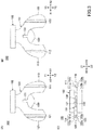
- FIG. 3 is a diagram illustrating the support plate 100 in the embodiment.
- FIG. 3A is a top view of the support plate 100.
- FIG. 3B is a bottom view of the support plate 100, and
- FIG. 3C is a rear view of the support plate 100.
- the support plate 100 has a support plate body 101, a handle 102.
- the support plate body 101 is a platelike member coupled to the handle 102.
- the support plate body 101 includes a right support portion 110 projecting from the handle 102 and branching to right and extending backward, and a left support portion 120 branching to left and extending backward. Also, the support plate body 101 includes a support platform 130 that protrudes backward from a central portion connecting the right support portion 110 to the left support portion 120.
- a right upper engagement groove 111 is formed on a top surface and a right lower engagement groove 112 is formed on a bottom surface.
- Each of the right upper engagement groove 111 and the right lower engagement groove 112 is formed parallel to the front-to-rear direction (Y1Y2 direction).
- the right upper engagement groove 111 includes a groove 111a, and an engagement groove 111b formed by making a dent on a right side of the groove 111a.
- the right lower engagement groove 112 includes a groove 112a, and an engagement groove 112b formed by making a dent on a left side of the groove 112a.
- a left upper engagement groove 121 is formed on a top side and a left lower engagement groove 122 is formed on a bottom side.
- Each of the left upper engagement groove 121 and the left lower engagement groove 122 is formed parallel to the front-to-rear direction (Y1Y2 direction).
- the left upper engagement groove 121 includes a groove 121a and an engagement groove 121b formed by making a dent on a left side of the groove 111a.
- the left lower engagement groove 122 includes a groove 122a and an engagement groove 122b formed by making a dent on a right side of the groove 122a.
- an upper central groove 131 is formed on an upper surface side and a lower central groove 132 is formed on a lower surface side.
- Each of the upper central groove 131 and the lower central groove 132 is formed parallel to the front-to-rear direction (Y1Y2 direction) and is open on one rear end.
- the handle 102 is formed in a rectangular plate shape and is coupled to the support plate body 101 on the back side. A user grasps the handle 102 to insert the dental tray system 10 to the oral cavity and to remove the dental tray system 10 from the oral cavity. Also, it is also possible to apply irregularities to the handle 102 and press the impression material to mark a midline, a pupil line, a tilt of a lip, and the like.
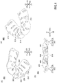
- FIG. 4 is a diagram illustrating the maxillary impression tray 200 in the embodiment.
- FIG. 4A is a perspective view from a top side of the maxillary impression tray 200.
- FIG. 4B is a perspective view from a lower side of the maxillary impression tray 200.
- FIG. 4C is a back view of the maxillary impression tray 200.
- the maxillary impression tray 200 is filled with on an impression material surface 203 between an outer edge 201 and an inner edge 202 to take an impression of the upper jaw side. As illustrated in FIG. 4 , the outer edge 201 and the inner edge 202 are formed to curve upward from an outer end and an inner edge of the impression material surface 203, respectively.
- a plurality of through holes 205 penetrating up-to-down direction are formed on the impression material surface 203.
- the impression material filled on the impression material surface 203 is partially extruded from the through holes 205 to a lower surface side at the impression taiking.
- the impression material extruded from the through holes 205 to the lower surface side expands and is integrated with the maxillary impression tray 200 along with the impression material on the impression material surface 203.
- a right upper engagement pin 211 On a lower surface of the maxillary impression tray 200, a right upper engagement pin 211, a left upper engagement pin 212, and an upper central pin 213 are formed. Each of the right upper engagement pin 211, the left upper engagement pin 212, and the upper central pin 213 is formed to project to a Z2 direction from the lower surface of the maxillary impression tray 200.
- the right upper engagement pin 211 includes a pin body 211a having a cylindrical shape, and an engagement portion 211b projecting to a right side from a lower end of the pin body 211a.
- the right upper engagement pin 211 is inserted into the right upper engagement groove 111 of the support plate 100 such that the engagement portion 211b fits into and engages the engagement groove 111b.
- the left upper engagement pin 212 includes a pin body 212a having a cylindrical shape, and an engagement portion 212b projecting to a left side from a lower end of the pin body 212a.
- the left upper engagement pin 212 is inserted into the left upper engagement groove 121 of the support plate 100 such that the engagement portion 212b fits into and engages the engagement groove 121b.
- the upper central pin 213 is formed in a center portion of the maxillary impression tray 200 in the right-to-left direction (X1X2 direction).
- the upper central pin 213 is formed in a cylindrical shape and is inserted into the upper central groove 131 of the support plate 100.
- FIG. 5 is a diagram illustrating the mandibular impression tray 300 in the embodiment.
- FIG. 5A is a perspective view from a top side of the mandibular impression tray 300.
- FIG. 5B is a perspective view from a lower side of the mandibular impression tray 300.
- FIG. 5C is a back view of the mandibular impression tray 300.
- the mandibular impression tray 300 is filled with on an impression material surface 303 between the outer edge 301 and the inner edge 302 to take the impression of the mandibular side within the oral cavity.
- the outer edge 301 and the inner edge 302 are formed so as to curve downward from an outer end and an inner end of the impression material surface 303, respectively.
- the impression material surface 303 is formed with the plurality of through holes 305 penetrating the up-to-down direction.
- the impression material on the impression material surface 303 is partially extruded from the through holes 305 to the upper surface at the impression taking.
- the impression material extruded from the through holes 305 to the top surface side expands and is integrated with the mandibular impression tray 300 along with the impression material on the impression material surface 303.
- a right lower engagement pin 311, a left lower engagement pin 312, and a lower central pin 313 are formed on an upper surface of the mandibular impression tray 300.
- Each of the right lower engagement pin 311, the left lower engagement pin 312, and the lower central pin 313 is formed to project from the upper surface of the mandibular impression tray 300 in the Z1 direction.
- the right lower engagement pin 311 includes a pin body 311a having a cylindrical shape and an engagement portion 311b projecting to left from an upper end of the pin body 311a.
- the right lower engagement pin 311 is inserted into the right lower engagement groove 112 of the support plate 100 such that the engagement portion 311b fits into and engages the engagement groove 112b.
- the left lower engagement pin 312 has a pin body 312a having a cylindrical shape, and an engagement portion 312b projecting to the right from the upper end of the pin body 312a.
- the left lower engagement pin 312 is inserted into the left lower engagement groove 122 of the support plate 100 such that the engagement portion 312b fits into and engages with the engagement groove 122b.
- the lower central pin 313 is formed in a center portion of the mandibular impression tray 300 in the right-to-left direction (X1X2 direction).
- the lower central pin 313 is formed in a cylindrical shape and is inserted into the lower central groove 132 of the support plate 100.
- FIG. 6 is a back view of the dental tray system 10 in the embodiment.
- the right upper engagement pin 211, the left upper engagement pin 212, and the upper central pin 213 are inserted into the right upper engagement groove 111, the left upper engagement groove 121, and the upper central groove 131, respectively, and are movably supported in the front-to-rear direction by the support plate 100. Also, by engaging the right upper engagement pin 211 and the left upper engagement pin 212 with the right upper engagement groove 111 and the left upper engagement groove 121 of the support plate 100, respectively, the maxillary impression tray 200 is movably supported in the front-to-rear direction without detaching from the support plate 100.
- the right lower engagement pin 311, the left lower engagement pin 312, and the lower central pin 313 are inserted into the right lower engagement groove 112, the left lower engagement groove 122, and the lower central groove 132, respectively, the mandibular impression tray 300 is movably supported in the front-to-rear direction by the support plate 100. Also, the mandibular impression tray 300 is movably supported in the front-to-rear direction without detaching from the support plate 100 by engaging the right lower engagement pin 311 and the left lower engagement pin 312 with the right lower engagement groove 112 and the left lower engagement groove 122 of the support plate 100, respectively.
- the dental tray system 10 is used for the bite registration, in which the impression material is filled in the maxillary impression tray 200 and the mandibular impression tray 300, in a state in which the maxillary impression tray 200 and the mandibular impression tray 300 are supported by the support plate 100.
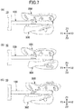
- FIG. 7 is a diagram illustrating how the maxillary impression tray 200 and the mandibular impression tray 300 in the embodiment move with respect to the support plate 100.
- the mandibular impression tray 300 is moved backward in the oral cavity of the patient, as illustrated in FIG. 7B .
- the mandibular impression tray 300 by moving the mandibular impression tray 300 backward more than the maxillary impression tray 200, it is possible to accurately perform the bite registration even in the occlusal relationship where the upper jaw protrudes to the lip side more than the lower jaw.
- the maxillary impression tray 200 is moved backward in the oral cavity of the patient, as illustrated in FIG. 7C .
- the maxillary impression tray 200 is moved backward more than the mandibular impression tray 300, it is possible to accurately perform the bite registration even in the occlusal relationship where the lower jaw protrudes to the lip side more than the upper jaw.
- FIG. 8 is a diagram illustrating a state in which the right upper engagement pin 211 is inserted into the right upper engagement groove 111, in the embodiment.
- FIG. 8A is a side view of the right upper engagement pin 211 and the right upper engagement groove 111.
- FIG. 8B is a view from a top view of an XY cross-section through the pin body 211a of the right upper engagement pin 211 inserted in the right upper engagement groove 111.
- FIG. 8 illustrates the right upper engagement pin 211 and the right upper engagement groove 111 in a state in which the upper central pin 213 is inserted into the upper central groove 131 and the maxillary impression tray 200 does not rotate relative to the support plate 100.
- the right upper engagement pin 211 is inserted into the right upper engagement groove 111 such that the engagement portion 211b fits into the engagement groove 111b.
- the engagement portion 211b of the right upper engagement pin 211 is formed in a shape of a semi-disk projecting in the X1 direction from a lower end of the pin body 211a, as depicted in FIG. 8A and FIG. 8B .
- the right upper engagement groove 111 and the right upper engagement pin 211 are formed so as to form a gap, and engage each other between a side wall of the right upper engagement groove 111 and the outer peripheral surface of the right upper engagement pin 211, as depicted in FIG. 8 .
- the gap is formed between the right upper engagement groove 111 and the right upper engagement pin 211, so that the right upper engagement pin 211 is rotatable in the right upper engagement groove 111.
- FIG. 9 is a diagram illustrating a state in which the right upper engagement pin 211 rotates in the right upper engagement groove 111, in the embodiment.
- FIG. 9A illustrates the right upper engagement pin 211 swinging counterclockwise in the right upper engagement groove 111.
- FIG. 9B illustrates a view in which the right upper engagement pin 211 rotates clockwise in the right upper engagement groove 111.
- the right upper engagement pin 211 may rotate so that the engagement portion 211b does not contact a side wall of the engagement groove 111b of the right upper engagement groove 111.
- the pin body 211a of the right upper engagement pin 211 is formed in a cylindrical shape so as not to contact the side wall of the right upper engagement groove 111 and prevent rotational movement.
- the left upper engagement groove 121 and the left upper engagement pin 212 are similarly formed and the left upper engagement pin 212 is rotatable in the left upper engagement groove 121.
- the same configuration as the right upper engagement groove 111 and the right upper engagement pin 211 enables the right lower engagement pin 311 to rotate in the right lower engagement groove 112, and the left lower engagement pin 312 to rotate in the left lower engagement groove 122.
- FIG. 10 is a diagram illustrating the upper central pin 213 of the maxillary impression tray 200 detached from the upper central groove 131 of the support plate 100.
- FIG. 10 for the maxillary impression tray 200, only the right upper engagement pin 211, the left upper engagement pin 212, and the upper central pin 213 are depicted.
- the maxillary impression tray 200 is moveably supported in the forward and backward directions by the support plate 100 by the right upper engagement pin 211 inserted into the right upper engagement groove 111, the left upper engagement pin 212 inserted into the left upper engagement groove 121, and the upper central pin 213 inserted into the upper central groove 131.
- the upper central groove 131 of the support plate 100 is formed so that a rear end is opened and leads to the support base 130. Accordingly, when the maxillary impression tray 200 is moved more backward than a length of the upper central groove 131, the upper central pin 213 is removed from the upper central groove 131 and is moveable back and forth and left and right on the support platform 130, as illustrated in FIG. 10B .
- the right upper engagement pin 211 is formed in the right upper engagement groove 111, such that it is callable of rotating.
- the left upper engagement pin 212 is formed in the left upper engagement groove 121, such that it is callable of rotating.
- FIG. 11 is a diagram illustrating how the maxillary impression tray 200 rotates in the embodiment.
- the maxillary impression tray 200 is moved backward (in the Y2 direction) and the upper central pin 213 is removed from the upper central groove 131 so as to be rotatable, for example, in a counterclockwise direction by a predetermined angle, as illustrated in FIG. 11 . Also, the maxillary impression tray 200 is rotated in the clockwise direction by a predetermined angle.
- the upper central pin 213 has a lower end surface that abuts the support base 130 and is supported by the support base 130. As described above, because the upper central pin 213 is supported on the support platform 130, the maxillary impression tray 200 is supported on the support plate 100 without downward tilting of the front portion even though the upper central pin 213 is rotatable away from the upper central groove 131.
- the mandibular impression tray 300 is moved backward (in the Y2 direction) and the lower central pin 313 is removed from the lower central groove 132, thereby allowing the mandibular impression tray 300 to rotate in a counterclockwise direction and a clockwise direction relative to the support plate 100 within a predetermined angle range.
- the support plate 100 is movably supported and rotatably supported in the forward and backward directions, respectively, with the maxillary impression tray 200 and the mandibular impression tray 300.
- the dental tray system 10 of the embodiment it is possible to respond not only to the forward and backward directions between the upper jaw and the lower jaw, but also to the right-to-lefts direction, so that the bite registration can be accurately performed according to anteroposterior and lateral occlusion states related to the maxilla and the mandible.
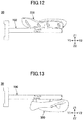
- only the maxillary impression can be taken by the dental tray system 20 having the maxillary impression tray 200 attached to the support plate 100 as illustrated in FIG. 12 .
- only the mandibular impression can be taken by the dental tray system 30 with the mandibular impression tray 300 attached to the support plate 100, as illustrated in FIG. 13 .
- shapes of the support plate 100, the maxillary impression tray 200, and the mandibular impression tray 300 are not limited to the shapes illustrated in the embodiment described above.
- the number of engagement grooves formed on the support plate 100, the number of engagement pins formed on the maxillary impression tray 200, and the mandibular impression tray 300 are not limited to the numbers illustrated in the above described embodiment.
- the shapes of the engagement grooves formed on the support plate 100, and the shapes of engagement pins formed on the maxillary impression tray 200 and the mandibular impression tray 300 are not limited to the shapes illustrated in the above described embodiment.
- the engagement grooves and the engagement pins may be in different shapes from those in the embodiment. Furthermore, a circular end of the engagement portion 211b can be rounded to expand the range of rotation.
Landscapes
- Health & Medical Sciences (AREA)
- Life Sciences & Earth Sciences (AREA)
- General Health & Medical Sciences (AREA)
- Oral & Maxillofacial Surgery (AREA)
- Dentistry (AREA)
- Epidemiology (AREA)
- Animal Behavior & Ethology (AREA)
- Public Health (AREA)
- Veterinary Medicine (AREA)
- Biomedical Technology (AREA)
- Biophysics (AREA)
- Engineering & Computer Science (AREA)
- Dental Prosthetics (AREA)
- Dental Tools And Instruments Or Auxiliary Dental Instruments (AREA)
Abstract
Description
- The present invention relates to a dental tray system.
- In order to ensure preferable occlusion in a manufacture of dentures and the like, it is necessary to accurately perform bite registration of a patient. Accordingly, a dental impression tray for simultaneously obtaining impressions of a maxilla and a mandible is known, in which a maxillary impression tray and a mandibular impression tray, on each which an impression material is filled, are integrally arranged in an oral cavity (for example, refer to Patent Document 1) .
- Patent Document 1: Japanese Laid-Open Patent Publication No.
2001-333917 - Occlusion states of the maxillary and the mandibular are different depending on the patient; the maxillary and the mandibular may be normal with no anteroposterior displacement, or one of the maxilla and the mandible may protrude anteriorly over the other. The dental impression tray described in Patent Document 1 described above fixes a maxillary impression tray and a mandibular impression tray with each other; hence, the dental impression tray may not correspond to an jaw position varying on each patient and may not be able to accurately obtain the bite registration.
- An objective of the present invention is to provide a dental tray system, which has been made in view of the above and is capable of accurately performing the bite registration depending on the jaw position.
- According to one aspect of the present invention, a dental tray system includes a maxillary impression tray configured to be filled with an impression material and to take an impression of an upper jaw side in an oral cavity; a mandibular impression tray configured to be filled with the impression material and to take the impression of a lower jaw side in the oral cavity; and a support plate provided between the maxillary impression tray and the mandibular impression tray, and configured to movably support the maxillary impression tray and the mandibular impression tray in a front-to-rear direction and to rotatably support the maxillary impression tray and the mandibular impression tray.
- According to an embodiment of the present invention, a dental tray system is provided that can accurately perform bite registration depending on the jaw position.
-
-
FIG. 1 is a perspective view of a dental tray system in an embodiment. -
FIG. 2 is a perspective view of a support plate in the embodiment. -
FIG. 3 is a diagram illustrating the support plate in the embodiment. -
FIG. 4 is a diagram illustrating a maxillary impression tray in the embodiment. -
FIG. 5 is a diagram illustrating a mandibular impression tray in the embodiment. -
FIG. 6 is a back view of the dental tray system in the embodiment. -
FIG. 7 is a view illustrating a movement of the maxillary impression tray and the mandibular impression tray in the embodiment. -
FIG. 8 is a diagram illustrating a state in which a right upper engagement pin is inserted into a right upper engagement groove, in the embodiment. -
FIG. 9 is a diagram illustrating a state in which the right upper engagement pin rotates in the right upper engagement groove, in the embodiment. -
FIG. 10 is a diagram illustrating an upper central pin of a maxillary impression tray detached from an upper central groove of the support plate. -
FIG. 11 is a diagram illustrating how the maxillary impression tray rotates in the embodiment. -
FIG. 12 is a side view of the dental tray system in the embodiment. -
FIG. 13 is a side view of the dental tray system in the embodiment. - Hereinafter, an embodiment of the present invention will be described with reference to the drawings. In each drawing, the same component parts may be denoted by the same reference numerals and duplicate descriptions may be omitted.
-
FIG. 1 is a perspective view of adental tray system 10 in the embodiment. Thedental tray system 10 is used for a bite registration of an edentulous jaw. In the following drawings, a X1X2 direction is a right-to-left direction of thedental tray system 10. A Y1Y2 direction is a front-to-rear direction of thedental tray system 10, and a Z1Z2 direction is an up-to-down direction of thedental tray system 10. In the following explanation, there are cases where a X1 direction indicates right, a X2 direction indicates left, a Y1 direction indicates front, a Y2 direction indicates rearward, a Z1 direction indicates upward, and a Z2 direction indicates downward. - As illustrated in
FIG. 1 , thedental tray system 10 has asupport plate 100, amaxillary impression tray 200, and amandibular impression tray 300. - The
support plate 100 movably supports each of the maxillary impression tray 200 and the mandibular impression tray 300 in the forward and backward directions. An impression material is filled on themaxillary impression tray 200 to take an impression of an upper jaw side of an oral cavity. The impression material is filled on themandibular impression tray 300 to take an impression of a lower jaw side of the oral cavity. - The
support plate 100, the maxillary impression tray 200, and themandibular impression tray 300 are formed, for example, of a resinous material. Each of thesupport plate 100, the maxillary impression tray 200, and themandibular impression tray 300 may be formed of a metal material or the like, and may be formed from a different material. -
FIG. 2 is a perspective view of thesupport plate 100 in the embodiment.FIG. 3 is a diagram illustrating thesupport plate 100 in the embodiment.FIG. 3A is a top view of thesupport plate 100.FIG. 3B is a bottom view of thesupport plate 100, andFIG. 3C is a rear view of thesupport plate 100. - As illustrated in
FIG. 2 andFIG. 3 , thesupport plate 100 has asupport plate body 101, ahandle 102. - The
support plate body 101 is a platelike member coupled to thehandle 102. Thesupport plate body 101 includes aright support portion 110 projecting from thehandle 102 and branching to right and extending backward, and aleft support portion 120 branching to left and extending backward. Also, thesupport plate body 101 includes asupport platform 130 that protrudes backward from a central portion connecting theright support portion 110 to theleft support portion 120. - On the
right support portion 110, a rightupper engagement groove 111 is formed on a top surface and a rightlower engagement groove 112 is formed on a bottom surface. Each of the rightupper engagement groove 111 and the rightlower engagement groove 112 is formed parallel to the front-to-rear direction (Y1Y2 direction). - As illustrated in
FIG. 3C , the rightupper engagement groove 111 includes agroove 111a, and anengagement groove 111b formed by making a dent on a right side of thegroove 111a. The rightlower engagement groove 112 includes agroove 112a, and anengagement groove 112b formed by making a dent on a left side of thegroove 112a. - On the
left support portion 120, a leftupper engagement groove 121 is formed on a top side and a leftlower engagement groove 122 is formed on a bottom side. Each of the leftupper engagement groove 121 and the leftlower engagement groove 122 is formed parallel to the front-to-rear direction (Y1Y2 direction). - As illustrated in
FIG. 3C , the leftupper engagement groove 121 includes agroove 121a and anengagement groove 121b formed by making a dent on a left side of thegroove 111a. The leftlower engagement groove 122 includes agroove 122a and anengagement groove 122b formed by making a dent on a right side of thegroove 122a. - Moreover, at a central portion, at which the
right support portion 110 and theleft support portion 120 are connected on thesupport plate body 101, an uppercentral groove 131 is formed on an upper surface side and a lowercentral groove 132 is formed on a lower surface side. Each of the uppercentral groove 131 and the lowercentral groove 132 is formed parallel to the front-to-rear direction (Y1Y2 direction) and is open on one rear end. - The
handle 102 is formed in a rectangular plate shape and is coupled to thesupport plate body 101 on the back side. A user grasps thehandle 102 to insert thedental tray system 10 to the oral cavity and to remove thedental tray system 10 from the oral cavity. Also, it is also possible to apply irregularities to thehandle 102 and press the impression material to mark a midline, a pupil line, a tilt of a lip, and the like. -
FIG. 4 is a diagram illustrating themaxillary impression tray 200 in the embodiment.FIG. 4A is a perspective view from a top side of themaxillary impression tray 200.FIG. 4B is a perspective view from a lower side of themaxillary impression tray 200.FIG. 4C is a back view of themaxillary impression tray 200. - The
maxillary impression tray 200 is filled with on animpression material surface 203 between anouter edge 201 and aninner edge 202 to take an impression of the upper jaw side. As illustrated inFIG. 4 , theouter edge 201 and theinner edge 202 are formed to curve upward from an outer end and an inner edge of theimpression material surface 203, respectively. - On the
impression material surface 203, a plurality of throughholes 205 penetrating up-to-down direction are formed. The impression material filled on theimpression material surface 203 is partially extruded from the throughholes 205 to a lower surface side at the impression taiking. The impression material extruded from the throughholes 205 to the lower surface side expands and is integrated with themaxillary impression tray 200 along with the impression material on theimpression material surface 203. - On a lower surface of the
maxillary impression tray 200, a rightupper engagement pin 211, a leftupper engagement pin 212, and an uppercentral pin 213 are formed. Each of the rightupper engagement pin 211, the leftupper engagement pin 212, and the uppercentral pin 213 is formed to project to a Z2 direction from the lower surface of themaxillary impression tray 200. - As illustrated in
FIG. 4C , the rightupper engagement pin 211 includes apin body 211a having a cylindrical shape, and anengagement portion 211b projecting to a right side from a lower end of thepin body 211a. The rightupper engagement pin 211 is inserted into the rightupper engagement groove 111 of thesupport plate 100 such that theengagement portion 211b fits into and engages theengagement groove 111b. - As illustrated in
FIG. 4C , the leftupper engagement pin 212 includes apin body 212a having a cylindrical shape, and anengagement portion 212b projecting to a left side from a lower end of thepin body 212a. The leftupper engagement pin 212 is inserted into the leftupper engagement groove 121 of thesupport plate 100 such that theengagement portion 212b fits into and engages theengagement groove 121b. - The upper
central pin 213 is formed in a center portion of themaxillary impression tray 200 in the right-to-left direction (X1X2 direction). The uppercentral pin 213 is formed in a cylindrical shape and is inserted into the uppercentral groove 131 of thesupport plate 100. -
FIG. 5 is a diagram illustrating themandibular impression tray 300 in the embodiment.FIG. 5A is a perspective view from a top side of themandibular impression tray 300.FIG. 5B is a perspective view from a lower side of themandibular impression tray 300.FIG. 5C is a back view of themandibular impression tray 300. - The
mandibular impression tray 300 is filled with on animpression material surface 303 between theouter edge 301 and theinner edge 302 to take the impression of the mandibular side within the oral cavity. As illustrated inFIG. 5 , theouter edge 301 and theinner edge 302 are formed so as to curve downward from an outer end and an inner end of theimpression material surface 303, respectively. - The
impression material surface 303 is formed with the plurality of throughholes 305 penetrating the up-to-down direction. The impression material on theimpression material surface 303 is partially extruded from the throughholes 305 to the upper surface at the impression taking. The impression material extruded from the throughholes 305 to the top surface side expands and is integrated with themandibular impression tray 300 along with the impression material on theimpression material surface 303. - On an upper surface of the
mandibular impression tray 300, a rightlower engagement pin 311, a leftlower engagement pin 312, and a lowercentral pin 313 are formed. Each of the rightlower engagement pin 311, the leftlower engagement pin 312, and the lowercentral pin 313 is formed to project from the upper surface of themandibular impression tray 300 in the Z1 direction. - As illustrated in
FIG. 5C , the rightlower engagement pin 311 includes apin body 311a having a cylindrical shape and anengagement portion 311b projecting to left from an upper end of thepin body 311a. The rightlower engagement pin 311 is inserted into the rightlower engagement groove 112 of thesupport plate 100 such that theengagement portion 311b fits into and engages theengagement groove 112b. - As illustrated in
FIG. 5C , the leftlower engagement pin 312 has apin body 312a having a cylindrical shape, and anengagement portion 312b projecting to the right from the upper end of thepin body 312a. The leftlower engagement pin 312 is inserted into the leftlower engagement groove 122 of thesupport plate 100 such that theengagement portion 312b fits into and engages with theengagement groove 122b. - The lower
central pin 313 is formed in a center portion of themandibular impression tray 300 in the right-to-left direction (X1X2 direction). The lowercentral pin 313 is formed in a cylindrical shape and is inserted into the lowercentral groove 132 of thesupport plate 100. -
FIG. 6 is a back view of thedental tray system 10 in the embodiment. - As illustrated in
FIG. 6 , regarding themaxillary impression tray 200, the rightupper engagement pin 211, the leftupper engagement pin 212, and the uppercentral pin 213 are inserted into the rightupper engagement groove 111, the leftupper engagement groove 121, and the uppercentral groove 131, respectively, and are movably supported in the front-to-rear direction by thesupport plate 100. Also, by engaging the rightupper engagement pin 211 and the leftupper engagement pin 212 with the rightupper engagement groove 111 and the leftupper engagement groove 121 of thesupport plate 100, respectively, themaxillary impression tray 200 is movably supported in the front-to-rear direction without detaching from thesupport plate 100. - The right
lower engagement pin 311, the leftlower engagement pin 312, and the lowercentral pin 313 are inserted into the rightlower engagement groove 112, the leftlower engagement groove 122, and the lowercentral groove 132, respectively, themandibular impression tray 300 is movably supported in the front-to-rear direction by thesupport plate 100. Also, themandibular impression tray 300 is movably supported in the front-to-rear direction without detaching from thesupport plate 100 by engaging the rightlower engagement pin 311 and the leftlower engagement pin 312 with the rightlower engagement groove 112 and the leftlower engagement groove 122 of thesupport plate 100, respectively. - As illustrated in
FIG. 6 , thedental tray system 10 is used for the bite registration, in which the impression material is filled in themaxillary impression tray 200 and themandibular impression tray 300, in a state in which themaxillary impression tray 200 and themandibular impression tray 300 are supported by thesupport plate 100. -
FIG. 7 is a diagram illustrating how themaxillary impression tray 200 and themandibular impression tray 300 in the embodiment move with respect to thesupport plate 100. - For example, in a case in which there is no significant misalignment between positions of an upper jaw and a lower jaw of a patient and an occlusal relationship is normal, as illustrated in
FIG. 7A , it is possible to perform the bite registration of the patient in a state in which themaxillary impression tray 200 and themandibular impression tray 300 are placed at approximately the same position in the front-to-rear direction (Y1Y2) direction. - For example, in a case of the occlusion relationship in which the upper jaw protrudes to the lip side rather than the lower jaw, the
mandibular impression tray 300 is moved backward in the oral cavity of the patient, as illustrated inFIG. 7B . As described above, by moving themandibular impression tray 300 backward more than themaxillary impression tray 200, it is possible to accurately perform the bite registration even in the occlusal relationship where the upper jaw protrudes to the lip side more than the lower jaw. - Moreover, for example, in the case of the occlusal relationship where the upper jaw protrudes to the lip side more than the lower jaw, the
maxillary impression tray 200 is moved backward in the oral cavity of the patient, as illustrated inFIG. 7C . As described above, by moving themaxillary impression tray 200 backward more than themandibular impression tray 300, it is possible to accurately perform the bite registration even in the occlusal relationship where the lower jaw protrudes to the lip side more than the upper jaw. -
FIG. 8 is a diagram illustrating a state in which the rightupper engagement pin 211 is inserted into the rightupper engagement groove 111, in the embodiment.FIG. 8A is a side view of the rightupper engagement pin 211 and the rightupper engagement groove 111.FIG. 8B is a view from a top view of an XY cross-section through thepin body 211a of the rightupper engagement pin 211 inserted in the rightupper engagement groove 111. -
FIG. 8 illustrates the rightupper engagement pin 211 and the rightupper engagement groove 111 in a state in which the uppercentral pin 213 is inserted into the uppercentral groove 131 and themaxillary impression tray 200 does not rotate relative to thesupport plate 100. - As illustrated in
FIG. 8A , the rightupper engagement pin 211 is inserted into the rightupper engagement groove 111 such that theengagement portion 211b fits into theengagement groove 111b. Theengagement portion 211b of the rightupper engagement pin 211 is formed in a shape of a semi-disk projecting in the X1 direction from a lower end of thepin body 211a, as depicted inFIG. 8A and FIG. 8B . - The right
upper engagement groove 111 and the rightupper engagement pin 211 are formed so as to form a gap, and engage each other between a side wall of the rightupper engagement groove 111 and the outer peripheral surface of the rightupper engagement pin 211, as depicted inFIG. 8 . Thus, the gap is formed between the rightupper engagement groove 111 and the rightupper engagement pin 211, so that the rightupper engagement pin 211 is rotatable in the rightupper engagement groove 111. -
FIG. 9 is a diagram illustrating a state in which the rightupper engagement pin 211 rotates in the rightupper engagement groove 111, in the embodiment.FIG. 9A illustrates the rightupper engagement pin 211 swinging counterclockwise in the rightupper engagement groove 111.FIG. 9B illustrates a view in which the rightupper engagement pin 211 rotates clockwise in the rightupper engagement groove 111. - As illustrated in
FIG. 9A and FIG. 9B , the rightupper engagement pin 211 may rotate so that theengagement portion 211b does not contact a side wall of theengagement groove 111b of the rightupper engagement groove 111. In this embodiment, thepin body 211a of the rightupper engagement pin 211 is formed in a cylindrical shape so as not to contact the side wall of the rightupper engagement groove 111 and prevent rotational movement. - Although the right
upper engagement groove 111 and the rightupper engagement pin 211 have been illustrated, the leftupper engagement groove 121 and the leftupper engagement pin 212 are similarly formed and the leftupper engagement pin 212 is rotatable in the leftupper engagement groove 121. The same configuration as the rightupper engagement groove 111 and the rightupper engagement pin 211 enables the rightlower engagement pin 311 to rotate in the rightlower engagement groove 112, and the leftlower engagement pin 312 to rotate in the leftlower engagement groove 122. -
FIG. 10 is a diagram illustrating the uppercentral pin 213 of themaxillary impression tray 200 detached from the uppercentral groove 131 of thesupport plate 100. InFIG. 10 , for themaxillary impression tray 200, only the rightupper engagement pin 211, the leftupper engagement pin 212, and the uppercentral pin 213 are depicted. - As illustrated in
FIG. 10A , themaxillary impression tray 200 is moveably supported in the forward and backward directions by thesupport plate 100 by the rightupper engagement pin 211 inserted into the rightupper engagement groove 111, the leftupper engagement pin 212 inserted into the leftupper engagement groove 121, and the uppercentral pin 213 inserted into the uppercentral groove 131. - The upper
central groove 131 of thesupport plate 100 is formed so that a rear end is opened and leads to thesupport base 130. Accordingly, when themaxillary impression tray 200 is moved more backward than a length of the uppercentral groove 131, the uppercentral pin 213 is removed from the uppercentral groove 131 and is moveable back and forth and left and right on thesupport platform 130, as illustrated inFIG. 10B . - As described above, the right
upper engagement pin 211 is formed in the rightupper engagement groove 111, such that it is callable of rotating. The leftupper engagement pin 212 is formed in the leftupper engagement groove 121, such that it is callable of rotating. With this configuration, themaxillary impression tray 200 is rotatable relative to thesupport plate 100 by allowing the uppercentral pin 213 to move back and forth left and right away from the uppercentral groove 131. -
FIG. 11 is a diagram illustrating how themaxillary impression tray 200 rotates in the embodiment. - The
maxillary impression tray 200 is moved backward (in the Y2 direction) and the uppercentral pin 213 is removed from the uppercentral groove 131 so as to be rotatable, for example, in a counterclockwise direction by a predetermined angle, as illustrated inFIG. 11 . Also, themaxillary impression tray 200 is rotated in the clockwise direction by a predetermined angle. - Even if it is removed from the upper
central groove 131, the uppercentral pin 213 has a lower end surface that abuts thesupport base 130 and is supported by thesupport base 130. As described above, because the uppercentral pin 213 is supported on thesupport platform 130, themaxillary impression tray 200 is supported on thesupport plate 100 without downward tilting of the front portion even though the uppercentral pin 213 is rotatable away from the uppercentral groove 131. - A manner, in which the
maxillary impression tray 200 rotates, is described, and themandibular impression tray 300 rotates in the same manner. Themandibular impression tray 300 is moved backward (in the Y2 direction) and the lowercentral pin 313 is removed from the lowercentral groove 132, thereby allowing themandibular impression tray 300 to rotate in a counterclockwise direction and a clockwise direction relative to thesupport plate 100 within a predetermined angle range. - Thus, in the
dental tray system 10 of the embodiment, thesupport plate 100 is movably supported and rotatably supported in the forward and backward directions, respectively, with themaxillary impression tray 200 and themandibular impression tray 300. - Therefore, according to the
dental tray system 10 of the embodiment, it is possible to respond not only to the forward and backward directions between the upper jaw and the lower jaw, but also to the right-to-lefts direction, so that the bite registration can be accurately performed according to anteroposterior and lateral occlusion states related to the maxilla and the mandible. - For example, when only the upper jaw side is used as a denture, only the maxillary impression can be taken by the
dental tray system 20 having themaxillary impression tray 200 attached to thesupport plate 100 as illustrated inFIG. 12 . For example, in a case in which only the upper jaw side is used as a denture, only the mandibular impression can be taken by thedental tray system 30 with themandibular impression tray 300 attached to thesupport plate 100, as illustrated inFIG. 13 . - Although the dental tray system according to the embodiment has been described above, the present invention is not limited to the above-described embodiment, and various modifications and improvements are possible within the scope of the present invention.
- For example, shapes of the
support plate 100, themaxillary impression tray 200, and themandibular impression tray 300 are not limited to the shapes illustrated in the embodiment described above. The number of engagement grooves formed on thesupport plate 100, the number of engagement pins formed on themaxillary impression tray 200, and themandibular impression tray 300 are not limited to the numbers illustrated in the above described embodiment. Also, the shapes of the engagement grooves formed on thesupport plate 100, and the shapes of engagement pins formed on themaxillary impression tray 200 and themandibular impression tray 300 are not limited to the shapes illustrated in the above described embodiment. If themaxillary impression tray 200 and themandibular impression tray 300 can be moved in the forward and backward directions without departing from thesupport plate 100, the engagement grooves and the engagement pins may be in different shapes from those in the embodiment. Furthermore, a circular end of theengagement portion 211b can be rounded to expand the range of rotation. - The patent application is based upon and claims the benefit of priority to Japanese Patent Application No.
2016-231328 filed November 29, 2016 2016-231328 -
- 10, 20, 30
- dental tray system
- 100
- support plate
- 200
- maxillary impression tray
- 300
- mandibular impression tray
- 111
- right upper engagement groove (upper engagement groove)
- 112
- right lower engagement groove (lower engagement groove)
- 121
- left upper engagement groove (upper engagement groove)
- 122
- lower left engagement groove (lower engagement groove)
- 131
- upper central groove
- 132
- lower central groove
- 211
- right upper engagement pin (upper engagement pin)
- 212
- left upper engagement pin (upper engagement pin)
- 213
- upper central pin
- 311
- right lower engagement pin (lower engagement pin)
- 312
- left lower engagement pin (lower engagement pin)
- 313
- lower central pin
Claims (6)
- A dental tray system, comprising:a maxillary impression tray configured to be filled with an impression material and to take an impression of an upper jaw side in an oral cavity;a mandibular impression tray configured to be filled with the impression material and to take the impression of a lower jaw side in the oral cavity; anda support plate provided between the maxillary impression tray and the mandibular impression tray, and configured to movably support the maxillary impression tray and the mandibular impression tray in a front-to-rear direction and to rotatably support the maxillary impression tray and the mandibular impression tray.
- The dental tray system as claimed in claim 1, wherein the support plate includes
an upper engagement groove formed along the front-to-rear direction on an upper surface supporting the maxillary impression tray; and
a lower engagement groove formed along the front-to-rear direction on a lower surface supporting the mandibular impression tray,
wherein the maxillary impression tray includes an upper engagement pin, which protrudes toward the support plate to engage in a loose fit in the upper engagement groove and is movable along the upper engagement groove, and
the mandibular impression tray includes a lower engagement pin, which protrudes toward the support plate to engage in a loose fit in the lower engagement groove and is movable along the lower engagement groove,
wherein the upper engagement pin rotates while engaging the upper engagement groove, so that the maxillary impression tray is rotated, and the lower engagement pin rotates while engaging the lower engagement groove, so that the mandibular impression tray is rotated. - The dental tray system as claimed in claim 2, wherein the maxillary impression tray includes an upper central pin that projects from a center in a right-to-left direction perpendicular to the front-to-rear direction toward the support plate and fits into an upper central groove formed in the support plate,
the mandibular impression tray includes a lower central pin that projects from the center in the right-to-left direction toward the support plate and fits into a lower central groove formed in the support plate, and
each of the upper central groove and the lower central groove is open to an end at a rear side. - A dental tray system, comprising:an impression tray being filled with an impression material for taking an impression in an oral cavity; anda support plate configured to movably support the impression tray in a front-to-rear direction and to rotatably support the impression tray.
- The dental tray system as claimed in claim 4, wherein
the support plate includes an engagement groove formed along the front-to-rear direction on a surface supporting the impression tray,
the impression tray includes an engagement pin that protrudes toward the support plate and engages in a loose fit in the engagement groove, and that is movable along the engagement groove, and
the engagement pin is rotated in an engagement with the engagement groove, so that the impression tray rotates. - The dental tray system as claimed in claim 5, wherein the impression tray includes a central pin that projects from a center in a right-to-left direction perpendicular to the front-to-rear direction toward the support plate, and that fits into a central groove formed in the support plate, and
the central groove opens an end at a rear side.
Applications Claiming Priority (2)
| Application Number | Priority Date | Filing Date | Title |
|---|---|---|---|
| JP2016231328 | 2016-11-29 | ||
| PCT/JP2017/033036 WO2018100838A1 (en) | 2016-11-29 | 2017-09-13 | Dental tray system |
Publications (2)
| Publication Number | Publication Date |
|---|---|
| EP3549547A1 true EP3549547A1 (en) | 2019-10-09 |
| EP3549547A4 EP3549547A4 (en) | 2020-07-29 |
Family
ID=62241541
Family Applications (1)
| Application Number | Title | Priority Date | Filing Date |
|---|---|---|---|
| EP17875795.1A Withdrawn EP3549547A4 (en) | 2016-11-29 | 2017-09-13 | Dental tray system |
Country Status (6)
| Country | Link |
|---|---|
| US (1) | US20190274795A1 (en) |
| EP (1) | EP3549547A4 (en) |
| JP (1) | JP6808752B2 (en) |
| KR (1) | KR20190075109A (en) |
| CN (1) | CN109982659A (en) |
| WO (1) | WO2018100838A1 (en) |
Families Citing this family (7)
| Publication number | Priority date | Publication date | Assignee | Title |
|---|---|---|---|---|
| KR102193807B1 (en) * | 2018-08-27 | 2020-12-22 | 전남대학교산학협력단 | Recording conversion system and method including mandibular movement sensor |
| KR102070682B1 (en) * | 2018-09-11 | 2020-01-29 | 전남대학교산학협력단 | Edentulous Tray and Recording conversion Method |
| KR102095273B1 (en) * | 2018-09-13 | 2020-04-23 | 주식회사 바텍 | Impressing tray and denture manufacturing process using the impressing tray and ct imaging apparatus |
| CN111214304B (en) * | 2020-01-21 | 2020-12-08 | 北京大学口腔医学院 | A jaw position recording tray and method for determining jaw position relationship |
| KR102467675B1 (en) * | 2020-10-28 | 2022-11-15 | 권우창 | Scanning guide for dental implant |
| KR102727558B1 (en) * | 2022-03-08 | 2024-11-06 | 전남대학교산학협력단 | Occlusal acquisition device |
| WO2025054875A1 (en) * | 2023-09-14 | 2025-03-20 | 趙子厚 | Digital occlusal conversion device |
Family Cites Families (9)
| Publication number | Priority date | Publication date | Assignee | Title |
|---|---|---|---|---|
| US1512686A (en) * | 1923-07-25 | 1924-10-21 | Harper George Albert | Dental impression tray |
| GB320820A (en) * | 1928-12-31 | 1929-10-24 | Josef Claude | Improvements in or relating to trays for taking dental impressions |
| US3890711A (en) * | 1974-04-18 | 1975-06-24 | William F Burns | Adjustable dental impression tray |
| US5297960A (en) * | 1992-11-23 | 1994-03-29 | Burns William F | Expandable dual dental impression tray |
| JP2000051239A (en) * | 1998-08-06 | 2000-02-22 | Sankin Ind Co | Dental tray |
| JP3542544B2 (en) | 2000-05-26 | 2004-07-14 | 昇 山本 | Dental impression tray |
| JP3181517U (en) * | 2012-10-24 | 2013-02-14 | 一茂 大澤 | Byte fork |
| KR101302702B1 (en) * | 2013-05-16 | 2013-09-03 | 김종화 | The apparatus for upper and lower tray of denture manufacturing |
| US20150118640A1 (en) * | 2013-10-29 | 2015-04-30 | Stephen Michael Schmitt | Intra Oral Dental Motion Recording Device and Method for the Digital Diagnosis, Computer Design and Manufacture of Dental Devices |
-
2017
- 2017-09-13 WO PCT/JP2017/033036 patent/WO2018100838A1/en not_active Ceased
- 2017-09-13 JP JP2018553671A patent/JP6808752B2/en active Active
- 2017-09-13 KR KR1020197015364A patent/KR20190075109A/en not_active Withdrawn
- 2017-09-13 EP EP17875795.1A patent/EP3549547A4/en not_active Withdrawn
- 2017-09-13 US US16/463,596 patent/US20190274795A1/en not_active Abandoned
- 2017-09-13 CN CN201780073099.XA patent/CN109982659A/en active Pending
Also Published As
| Publication number | Publication date |
|---|---|
| WO2018100838A1 (en) | 2018-06-07 |
| CN109982659A (en) | 2019-07-05 |
| JP6808752B2 (en) | 2021-01-06 |
| KR20190075109A (en) | 2019-06-28 |
| US20190274795A1 (en) | 2019-09-12 |
| EP3549547A4 (en) | 2020-07-29 |
| JPWO2018100838A1 (en) | 2019-10-17 |
Similar Documents
| Publication | Publication Date | Title |
|---|---|---|
| US20190274795A1 (en) | Dental tray system | |
| JP6751712B2 (en) | Dental appliance with repositioning jaw element | |
| US10973612B2 (en) | Dental appliance binding structure | |
| EP3007646B1 (en) | Method for taking a dental impression in the mouth | |
| US20150238280A1 (en) | Dental appliance with repositioning jaw elements | |
| EP2574303B1 (en) | Dental impression tray | |
| EP3549548A1 (en) | Tray system for dentistry | |
| EP3111886B1 (en) | Tool for obtaining dental occlusion in patient with edentulous jaw | |
| BRPI0904212A2 (en) | fast and simple positioning and repositioning equipment of the arches without the use of plaster, which allows the simulation of the mandibular movement and its method of operation. | |
| JPH07104649B2 (en) | Dental denture-skull model | |
| US6558161B2 (en) | Completely reproducible articulator | |
| US20060204920A1 (en) | Dental articulator and method for using same | |
| US3722099A (en) | Method of accurately and precisely constructing artificial dentures | |
| US20160157972A1 (en) | Dental transfer template | |
| KR101686844B1 (en) | Articulator | |
| CN209422139U (en) | An adjustable dental impression tray | |
| JP2001112786A (en) | Impression molding tray | |
| CN219963128U (en) | a gothic bow tracing device | |
| KR101432420B1 (en) | articulator | |
| KR101825893B1 (en) | Dental Articulator That Copying Mandibular Movement | |
| JP2688737B2 (en) | Articulator | |
| JP2023081216A (en) | Bite taking device for full denture and bite taking method | |
| ITVR20000088A1 (en) | MOUNTING PLATE FOR ARTICULATORS FOR DENTAL USE FOR DENTAL OR SIMILAR PROSTHESES |
Legal Events
| Date | Code | Title | Description |
|---|---|---|---|
| PUAI | Public reference made under article 153(3) epc to a published international application that has entered the european phase |
Free format text: ORIGINAL CODE: 0009012 |
|
| 17P | Request for examination filed |
Effective date: 20190529 |
|
| AK | Designated contracting states |
Kind code of ref document: A1 Designated state(s): AL AT BE BG CH CY CZ DE DK EE ES FI FR GB GR HR HU IE IS IT LI LT LU LV MC MK MT NL NO PL PT RO RS SE SI SK SM TR |
|
| AX | Request for extension of the european patent |
Extension state: BA ME |
|
| DAV | Request for validation of the european patent (deleted) | ||
| DAX | Request for extension of the european patent (deleted) | ||
| A4 | Supplementary search report drawn up and despatched |
Effective date: 20200624 |
|
| RIC1 | Information provided on ipc code assigned before grant |
Ipc: A61C 9/00 20060101AFI20200619BHEP |
|
| STAA | Information on the status of an ep patent application or granted ep patent |
Free format text: STATUS: THE APPLICATION HAS BEEN WITHDRAWN |
|
| 18W | Application withdrawn |
Effective date: 20200902 |