EP3549526B1 - Time-correction device for pet system - Google Patents
Time-correction device for pet system Download PDFInfo
- Publication number
- EP3549526B1 EP3549526B1 EP17892689.5A EP17892689A EP3549526B1 EP 3549526 B1 EP3549526 B1 EP 3549526B1 EP 17892689 A EP17892689 A EP 17892689A EP 3549526 B1 EP3549526 B1 EP 3549526B1
- Authority
- EP
- European Patent Office
- Prior art keywords
- time
- ring
- module
- pet system
- correction device
- Prior art date
- Legal status (The legal status is an assumption and is not a legal conclusion. Google has not performed a legal analysis and makes no representation as to the accuracy of the status listed.)
- Active
Links
Images



Classifications
-
- G—PHYSICS
- G01—MEASURING; TESTING
- G01T—MEASUREMENT OF NUCLEAR OR X-RADIATION
- G01T1/00—Measuring X-radiation, gamma radiation, corpuscular radiation, or cosmic radiation
- G01T1/29—Measurement performed on radiation beams, e.g. position or section of the beam; Measurement of spatial distribution of radiation
- G01T1/2914—Measurement of spatial distribution of radiation
- G01T1/2985—In depth localisation, e.g. using positron emitters; Tomographic imaging (longitudinal and transverse section imaging; apparatus for radiation diagnosis sequentially in different planes, steroscopic radiation diagnosis)
-
- A—HUMAN NECESSITIES
- A61—MEDICAL OR VETERINARY SCIENCE; HYGIENE
- A61B—DIAGNOSIS; SURGERY; IDENTIFICATION
- A61B6/00—Apparatus or devices for radiation diagnosis; Apparatus or devices for radiation diagnosis combined with radiation therapy equipment
- A61B6/42—Arrangements for detecting radiation specially adapted for radiation diagnosis
- A61B6/4208—Arrangements for detecting radiation specially adapted for radiation diagnosis characterised by using a particular type of detector
- A61B6/4258—Arrangements for detecting radiation specially adapted for radiation diagnosis characterised by using a particular type of detector for detecting non x-ray radiation, e.g. gamma radiation
-
- A—HUMAN NECESSITIES
- A61—MEDICAL OR VETERINARY SCIENCE; HYGIENE
- A61B—DIAGNOSIS; SURGERY; IDENTIFICATION
- A61B6/00—Apparatus or devices for radiation diagnosis; Apparatus or devices for radiation diagnosis combined with radiation therapy equipment
-
- A—HUMAN NECESSITIES
- A61—MEDICAL OR VETERINARY SCIENCE; HYGIENE
- A61B—DIAGNOSIS; SURGERY; IDENTIFICATION
- A61B6/00—Apparatus or devices for radiation diagnosis; Apparatus or devices for radiation diagnosis combined with radiation therapy equipment
- A61B6/02—Arrangements for diagnosis sequentially in different planes; Stereoscopic radiation diagnosis
- A61B6/03—Computed tomography [CT]
-
- A—HUMAN NECESSITIES
- A61—MEDICAL OR VETERINARY SCIENCE; HYGIENE
- A61B—DIAGNOSIS; SURGERY; IDENTIFICATION
- A61B6/00—Apparatus or devices for radiation diagnosis; Apparatus or devices for radiation diagnosis combined with radiation therapy equipment
- A61B6/02—Arrangements for diagnosis sequentially in different planes; Stereoscopic radiation diagnosis
- A61B6/03—Computed tomography [CT]
- A61B6/032—Transmission computed tomography [CT]
-
- A—HUMAN NECESSITIES
- A61—MEDICAL OR VETERINARY SCIENCE; HYGIENE
- A61B—DIAGNOSIS; SURGERY; IDENTIFICATION
- A61B6/00—Apparatus or devices for radiation diagnosis; Apparatus or devices for radiation diagnosis combined with radiation therapy equipment
- A61B6/02—Arrangements for diagnosis sequentially in different planes; Stereoscopic radiation diagnosis
- A61B6/03—Computed tomography [CT]
- A61B6/037—Emission tomography
-
- A—HUMAN NECESSITIES
- A61—MEDICAL OR VETERINARY SCIENCE; HYGIENE
- A61B—DIAGNOSIS; SURGERY; IDENTIFICATION
- A61B6/00—Apparatus or devices for radiation diagnosis; Apparatus or devices for radiation diagnosis combined with radiation therapy equipment
- A61B6/42—Arrangements for detecting radiation specially adapted for radiation diagnosis
- A61B6/4208—Arrangements for detecting radiation specially adapted for radiation diagnosis characterised by using a particular type of detector
-
- A—HUMAN NECESSITIES
- A61—MEDICAL OR VETERINARY SCIENCE; HYGIENE
- A61B—DIAGNOSIS; SURGERY; IDENTIFICATION
- A61B6/00—Apparatus or devices for radiation diagnosis; Apparatus or devices for radiation diagnosis combined with radiation therapy equipment
- A61B6/42—Arrangements for detecting radiation specially adapted for radiation diagnosis
- A61B6/4266—Arrangements for detecting radiation specially adapted for radiation diagnosis characterised by using a plurality of detector units
-
- A—HUMAN NECESSITIES
- A61—MEDICAL OR VETERINARY SCIENCE; HYGIENE
- A61B—DIAGNOSIS; SURGERY; IDENTIFICATION
- A61B6/00—Apparatus or devices for radiation diagnosis; Apparatus or devices for radiation diagnosis combined with radiation therapy equipment
- A61B6/42—Arrangements for detecting radiation specially adapted for radiation diagnosis
- A61B6/4275—Arrangements for detecting radiation specially adapted for radiation diagnosis using a detector unit almost surrounding the patient, e.g. more than 180°
-
- A—HUMAN NECESSITIES
- A61—MEDICAL OR VETERINARY SCIENCE; HYGIENE
- A61B—DIAGNOSIS; SURGERY; IDENTIFICATION
- A61B6/00—Apparatus or devices for radiation diagnosis; Apparatus or devices for radiation diagnosis combined with radiation therapy equipment
- A61B6/44—Constructional features of apparatus for radiation diagnosis
- A61B6/4411—Constructional features of apparatus for radiation diagnosis the apparatus being modular
-
- A—HUMAN NECESSITIES
- A61—MEDICAL OR VETERINARY SCIENCE; HYGIENE
- A61B—DIAGNOSIS; SURGERY; IDENTIFICATION
- A61B6/00—Apparatus or devices for radiation diagnosis; Apparatus or devices for radiation diagnosis combined with radiation therapy equipment
- A61B6/54—Control of apparatus or devices for radiation diagnosis
-
- A—HUMAN NECESSITIES
- A61—MEDICAL OR VETERINARY SCIENCE; HYGIENE
- A61B—DIAGNOSIS; SURGERY; IDENTIFICATION
- A61B6/00—Apparatus or devices for radiation diagnosis; Apparatus or devices for radiation diagnosis combined with radiation therapy equipment
- A61B6/58—Testing, adjusting or calibrating thereof
- A61B6/582—Calibration
-
- A—HUMAN NECESSITIES
- A61—MEDICAL OR VETERINARY SCIENCE; HYGIENE
- A61B—DIAGNOSIS; SURGERY; IDENTIFICATION
- A61B6/00—Apparatus or devices for radiation diagnosis; Apparatus or devices for radiation diagnosis combined with radiation therapy equipment
- A61B6/58—Testing, adjusting or calibrating thereof
- A61B6/582—Calibration
- A61B6/585—Calibration of detector units
Definitions
- the present application relates to a time correction device in the field of medical devices, in particular to a time correction device for a PET system.
- Positron Emission Tomography (PET) system is a non-invasive molecular imaging device for functional metabolism, the principle of which is read as: radioactive nuclide decay produces positrons which will annihilate through combination with the electrons in a tissue after moving a short distance (usually a few millimeters), and the mass of which is converted into a pair of gamma photons that emit energy of 0.511 MeV in the opposite direction respectively; Doctors are thereby assisted in making relevant diagnoses for diseases by means of using the positron nuclides labeled on a molecular probe as tracers, acquiring time, energy and position information of the gamma photons generated from the annihilations of the positrons through detecting, obtaining Line of Response (also referred to as LOR) to the annihilation events by using coincidence technique, and then adopting an image reconstruction algorithm for imaging to reflect the degree of ingestion of the tracer at each part of body.
- LOR Line of Response
- the coincidence time resolution is an important indicator of the PET system. It expresses the uncertainty of the arrival of a pair of gamma photons after the annihilation event in the PET system, which is also known as response fluctuation. From the definition of time resolution, we can know that the response line will increase accordingly in the detector design using a crystal array. Each response line corresponds to a time spectrum. The time spectra corresponding to many response lines are combined into the time spectrum of the basic unit module.
- the direct measurement correction method for time correction is adopted by most PET, wherein the rotating rod source time correction method is more classic.
- the rotating rod source time correction method utilizes a rod source used in transmission scanning, collects coincidence data and performs iterative processing, etc. for time correction while the rod source is doing circular motion around the detector ring for decay correction.
- this method utilizes the decay correction rod source in a classic PET to carry on the correction without the need for additional equipment for classic clinical PET instruments.
- PET/CT is gradually popular in the market.
- PET/CT directly refers to the density information of the imaging tissue reflected by CT image and thus generates the decay factor required for PET decay correction, which makes most new instruments no longer rely on rotating rod sources when making decay corrections and further makes this method face a certain challenge in PET/CT state.
- Some direct measurement correction methods are also provided for time correction by using an iterative calculation method after data are acquired by placing a solid line source, a rod source or a tracer injected cylindrical prosthesis or ring-shaped prosthesis in the center of a detector ring (See Willians J. Automated coincidence timing calibration for a pet scanner, US5272344A , and Xiaoli Li, Burr, K.C, Gin-Chung Wang, Huini Du, etc. Timing calibration for time-of-flight PET using positron-emitting isotopes and annihilation targets, IEEE Nucl. Sci. Symp. Conf. Rec., pp. 1-5, 2013 ).
- Rotating rod source time correction method mostly uses an iterative algorithm with a large amount of basic data and a high algorithm complexity of O(n 2 ).
- O(n 2 ) is of square order and herein refers to the statement execution times in the algorithm, wherein n means each basic unit and can also be understood as the number of crystal lattices.
- the iterative algorithm takes relatively long operation time to obtain the final result.
- the rotating rod source generally adopts 68-Ge which has a half-life period of 270.95 days.
- the Ge source needs to be replaced after a certain time, which directly increases the operation cost of PET.
- Some PET systems are provided that the ring-shaped prosthesis is placed at the center of their detector rings. Similar to the method of using rotating rod source, a complex iterative algorithm is used to obtain the final correction result, of which computational complexity is high, is O(n 2 ) and leads to relatively long operation time although its acquisition time is short. Thus, in order to speed up the operation in practical applications, an additional high-performance computing server is required and the cost of the PET system is increased.
- a method using a time probe is also provided for time correction, which fixes the radioactive source and the crystal together onto the center of the FOV as a reference to obtain the time shifts between it and each module.
- its correction unit is mostly a basic module and is not accurate to the minimum basic unit "crystal lattice".
- the radioactive source used for the fixation is 68-Ge which has a half-life period of 270 days or 22-Na which has a half-life period of 2.6 years. That means the radioactive source must be replaced in order to maintain the performance of the PET system after a certain period of time.
- Document US2007131857 A1 may be considered to disclose a time correction device for a PET system, comprising:
- the purpose of the present application is to provide a time correction device for a PET system, so as to overcome the problem in the prior art of incomplete correction effect, complicated algorithm, and high equipment cost when making time correction for PET systems.
- a time correction device for a PET system comprising a detector ring which comprises a plurality of detectors arranged in sequence ; a ring-shaped prosthesis which is located in the detector ring with its center overlapping with an axial and radial center of the detector ring; a detection module which is located in the ring-shaped prosthesis with its center located at the center of the ring-shaped prosthesis; a data acquiring module which is provided with a data collecting module including the detectors and the detection module and an energy filtering module receiving single-event time information sent from said data collecting module, which are connected with each other; a data coincidence module which is connected to the energy filtering module and receives single-event time information sent from said energy filtering module; a time shift calculation module which is connected to the data coincidence module and obtains shift values of the detectors through the single-event time information; and a data correction application module which is configured to apply the shift values to an entire system to correct single-event time information.
- the axial length of the ring-shaped prosthesis does not exceed the axial length of the detector ring, and the outer diameter of the ring-shaped prosthesis does not exceed the inner diameter of the detector ring.
- the inner diameter of the ring-shaped prosthesis is between half of the diameter of the detector ring and the outer diameter of the detection module.
- the ring-shaped prosthesis is uniform in thickness.
- the ring-shaped prosthesis has a radioactive source, and activity of the radioactive source satisfies the condition that a total counting rate of a PET system after the radioactive source is placed is at least twice the counting rate of the PET system under empty scanning.
- the activity of the radioactive source in the ring-shaped prosthesis is provided in the range of 30 ⁇ 500uCi.
- the time resolution of the detection module is higher than that of the detectors in the detector ring.
- the detection module is provided with high-time performance with a time resolution of less than 1 ns.
- the detection module is also provided with a lutetium-yttrium oxy-orthosilicate scintillation crystal, a photoelectric conversion device and an electronic readout section, in which the lutetium-yttrium oxy-orthosilicate scintillation crystal is coupled to the photoelectric conversion device that is connected to the electronic readout section.
- the photoelectric conversion device is one selected from the group consisting of a photomultiplier tube, a silicon photomultiplier tube, a multi-pixel photon counter and a Geiger mode avalanche diode.
- the data gathering module acquires tabular single-event time information through the detectors in the detector ring and the detection module, and the energy filtering module analyzes and filters the single-event time information collected by the data gathering module through a certain energy window and filter out scattering events.
- the present application adopts a ring-shaped prosthesis instead of using a rotating rod source, which greatly reduces the design of the PET system and controls the complexity of the design of PET system. Moreover, the use of the ring-shaped prosthesis for time correction operation also has an advantage of easy operation, and is thus better adapted to popular PET or PET/CT instruments today.
- the present application places a detection module into the center of the field of view as a time reference to the detectors in the detector ring so that the complexity of algorithm is reduced through the method of using the same reference.
- the present application just needs to collect data once statically when correction, and thus the algorithm is fast and efficient, which reduces the complexity and the computation time compared with the iterative optimization correction algorithm heavily used in the prior art.
- Fig. 1 is a schematic view showing an arrangement of a time correction device for a PET system provided by the present application.
- the time correction device comprises a detector ring 10, a ring-shaped prosthesis 20 and a detection module 30.
- the detector ring 10 is composed of a plurality of detectors 11 which are arranged in sequence to form a ring.
- the ring-shaped prosthesis 20 is located inside the detector ring 10 with its center overlapping with the axial and radial center of the detector ring 10.
- the detection module 30 is located inside the ring-shaped prosthesis 20 with its center located at the center of the detector ring 10 and the ring-shaped prosthesis 20.
- the axial length of the ring-shaped prosthesis 20 does not exceed the axial length of the detector ring 10, the outer diameter of the ring-shaped prosthesis 20 does not exceed the inner diameter of the detector ring 10, and the inner diameter of the ring-shaped prosthesis 20 is not less than the outer diameter of the detection module 30.
- the inner diameter of the ring-shaped prosthesis 20 is between the half of the diameter of the detector ring 10 and the diameter of the detection module 30.
- the ring-shaped prosthesis 20 is uniform in thickness and is not easy to be deformed. In order to avoid background and random noise interference, radioactive source needs to be injected into the ring-shaped prosthesis 20 for making correction.
- the activity of radioactive source is preferably defined so that an overall counting rate of a PET system after setting the radioactive source is at least twice or higher, preferably 10 times higher than the counting rate of the PET system under empty scanning.
- the radioactive source inside the ring-shaped prosthesis 20 is a liquid positron source commonly used in PET systems, such as, 18 F-FDG, 18 F-FDOPA, 18 F-FLT, etc. based on 18 F, 15 O-H 2 O based on 15 O, 11 C-sodium acetate, 11C-choline, etc. based on 11 C.
- the activity of the radioactive source in the ring-shaped prosthesis 20 of the present application is preferably 30 to 500 uCi, and more preferably 300 to 500 uCi with low cost and good flexibility.
- the shape of the detector ring 10 is circular ring-shaped. It is contemplated for skilled person in the art that the detector ring according to the present application is not limited to be circular ring-shaped and can also be different ring-shaped or even not ring-shaped detectors.
- the detectors of detector ring 10 can be arranged in a form of flat plate, quadrangle or octagon.
- the detection module 30 in the PET system of the present application adopts a detection module with high time performance.
- the detection module 30 can be considered to be with high time performance in the present application. Meanwhile, due to the difference between various PET instruments clinically in their time resolution, the high time performance of detection module in the present application is less than 1 ns.
- the detection module 30 itself is rather small, which may be of other shapes and not limited to a circular shape.
- Fig. 2 is a schematic diagram showing the structure of a detection module 30 of a time correction device for a PET system in accordance with a preferred embodiment of the present application.
- the detection module 30 includes a lutetium-yttrium oxy-orthosilicate scintillation crystal 31 (referred to as LYSO crystal), a photoelectric conversion device 32 and an electronic readout section 33.
- the LYSO crystal 31 is coupled to the photoelectric conversion device 32.
- the photoelectric conversion device 32 is connected to the electronic readout section 33.
- the connection of the electronic readout section 33 and the data collection section belongs to common sense of this field.
- the photoelectric conversion device 32 adopts a photomultiplier tube (PMT) with a model number of Hamamatsu R9800 in the embodiment of Fig. 2 , for example.
- PMT photomultiplier tube
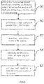
- Fig. 3 is a flow diagram of a time correction device for a PET system in accordance with a preferred embodiment of the present application.
- the steps of use of the time correction device of the present application are as follows:
- step S4 a coincidence time distribution is acquired from the coincidence events obtained by respective crystal lattices in the detector ring 10 with respect to the detection module 30 and thereby relative time shifts t n are obtained, in which n is a crystal lattice number and a positive integer.
- the step S4 of the present application provides a direct measurement calculation method to obtain time shift for each crystal lattice and then obtains a correction parameter, which leads to a high-speed, simple and effective algorithm and therefore the complexity and computing time are dramatically decreased.
- step S5 the obtained relative time shifts t n of respective crystal lattices are applied to the system.
- the time information in the original data is corrected during acquiring a single event. Namely, the obtained relative time shifts t n , are subtracted or added depending upon the calculation method of the relative time shifts into the original time information.
- Fig. 4 is a system diagram of a time correction device for a PET system in accordance with a preferred embodiment of the present application.
- the system of the time correction device provided by the present application includes a data acquisition module 100, a data coincidence module 200, a time shift calculation module 300 and a data correction application module 400.
- the data acquisition module 100 includes a data gathering module 110 and an energy filtering module 120 connected to each other, wherein the energy filtering module 120 is connected to the data coincidence module 200 and transmits the collected single-event time information to the data coincidence module 200.
- the data acquisition module 100 is configured to acquire single-event time information of each detector on the detection module and the detector ring and to preprocess partially the single-event time information by using an energy window.
- the data gathering module 110 is used to acquire the tabular single-event time information of each detector on the detection module and the detector ring and then transmit and store it into an upper computer server for processing.
- the energy filtering module 120 is used to analyze and filter the original single-event time information collected by the data gathering module 110 through a certain energy window and finally filter out scattering events.
- the data gathering module 110 is the sum of the detectors in the detector ring 10 and the detection module 30.
- the data gathering module 110 acquires the tabular single-event time information generated by detectors 11 of the detector ring 10 and the detection module 30.
- the data gathering module 110 transmits and stores the above single-event time information into the upper computer server for processing through connection with the energy filtering module 120.
- the energy filtering module 120 in the upper computer server analyzes and filters the original single-event time information collected by the data gathering module 110 through a certain energy window and finally filter out scattering events. It should be understood that the selection of the energy window can be determined by a person skilled in the art according to the needs for specific information collection.
- the energy filtering module 120 can be integrated in the respective detectors 11 on the detector ring 10 and the detection module 30 so that the scattering events can be filtered out through the energy filtering module 120 and then single-event time information is uploaded to the upper computer server through the data gathering module 110.
- the data collection efficiency is higher in that mode when activity of radioactive source is relatively high.
- the data conforming module 200 is used to perform data coincidence operations on the single-event time information acquired by the data acquiring module 100 according to the set time window and other conditions so as to obtain coincidence data of each crystal lattice on each detector relative to the detection module.
- the energy filtering module 120 sets several different filtering ranges, such as 350-650 keV, 250-750 keV, etc..
- the data coincidence module 200 performs data coincidence accordingly and obtains coincidence data of each crystal lattice of each detector on the detector ring 10 relative to the detection module 30 with high time performance.
- the time shift calculation module 300 is configured to acquire time distribution for the coincidence data of each crystal lattice relative to the detection module, and to obtain its shift values t n , wherein n is a crystal lattice number and is a positive integer.
- the data correction application module 400 is configured to apply the obtained shift values t n of the respective crystal lattices to the entire system and to perform time correction operations on the time information in each acquired single event. Specifically, time information correction is performed on the time information in tabular single-event time information acquired by the data acquisition module 100 by removing the obtained shift values t n .
- the calculation method and the correction method of the shift values t n are mentioned as the above step S5.
- Fig. 5 is a schematic diagram showing time distribution of a time correction device for a PET system in accordance with a preferred embodiment of the present application.
- a broken line e represents time distribution of a system composed of all detectors in the detector ring 10 before time correction, in which the time resolution of is 1.7 ns and the center value is 121.8 ps.
- a solid line f represents time distribution of a system composed of all detectors after time correction, in which the time resolution is 1.26 ns and the center value is -3.6 ps.
- the time resolution according to the present application is more advantageous to the implementation of TOF-PET technology (time-of-fiight PET technology) relative to the time resolution of 400-500 ps in the prior art.
- Figs. 6 and 7 respectively show a random coincidence and a NECR curve distribution before and after time correction of the system.
- Fig. 6 is a schematic diagram showing a comparison of random coincidence for a time correction device for a PET system in accordance with a preferred embodiment of the present application, in which a broken line represents that no time correction is made and a solid line represents that time correction is made.
- Fig. 7 is a schematic diagram showing a comparison of NECR curve for a time correction device for a PET system in accordance with a preferred embodiment of the present application, in which a broken line represents that no time correction is made and a solid line represents that time correction is made.
- the random coincidence event will decrease with the decrease of the time window, and the size of the time window is determined upon time resolution which is generally twice the time resolution.
- the small quantity of random coincidence events which is reflected in the final imaging indicates that image quality (signal-to-noise ratio) will be improved.
- the NECR curve is obtained by testing the NECR prosthesis according to the method used in the NEMA-NU4 standard. It can be seen from Fig. 6 that the random coincidence distribution after the use of time correction is lower than before. Moreover, it can be seen from Fig. 7 that NECR gets a large boost before and after time correction almost without much change in the true event. The range of improvement can be seen from Fig. 6 . The counting rate is nearly reduced by half over the entire activity range.
- the present application adopts a ring-shaped prosthesis instead of a rotating rod source, which greatly reduces the needs of design of PET system and allows the complexity of the design of PET system to be controllable. Moreover, the use of the ring-shaped prosthesis for time correction operation makes it easy to operate, and is thus better adapted to popular PET or PET/CT instruments today.
- the present application introduces a detection module, in particular, a detection module with high time performance to be placed into the center of the field of view as a time reference to the detectors in the detector ring. Therefore the complexity of algorithm is reduced through the method of using the same reference.
- the present application just needs to collect data once statically when correction and let the time complexity at this moment be known as O(n), wherein n is the total number of crystal lattices on the detector ring.
- the algorithm is fast, simple and efficient so as to reduce the complexity and the computation time compared with the iterative optimization correction algorithm heavily used in the prior art.
- the present application can also involve making crystal time correction for the smallest detection unit on the detector ring namely, the small crystal lattice.
- the calculation correction efficiency can be improved by using that calculation method.
- the structure of the detection module 30 in the present application may be a CZT detector readout through crystal/photoelectric conversion device/electronic, crystal/photoconductive/photoelectric conversion device/electronic, or photoelectric conversion device/electronic.
- the crystal used in the detection module with high-time performance of the present application may be in various kinds such as LaBr 3 , LSO, LYSO, LuYAP, BaF 2 , GSO, LFS or Lul 3 ,etc., and the shape of it may be cylindrical, elongated, tapered, and the like.
- the photoelectric conversion device used in the detection module with high time performance of the present application may be a photomultiplier tube, a silicon photomultiplier (SiPM), a multi-pixel photon counter (MPPC), a Geiger-mode avalanche photodiode (G-APD), etc., as long as the transit time distribution (TTS) is less than 500 ps. Accordingly, the scope of legal protection afforded this application can only be determined by studying the following claims.
Landscapes
- Health & Medical Sciences (AREA)
- Life Sciences & Earth Sciences (AREA)
- Engineering & Computer Science (AREA)
- Medical Informatics (AREA)
- Physics & Mathematics (AREA)
- High Energy & Nuclear Physics (AREA)
- Molecular Biology (AREA)
- General Health & Medical Sciences (AREA)
- Surgery (AREA)
- Veterinary Medicine (AREA)
- Nuclear Medicine, Radiotherapy & Molecular Imaging (AREA)
- Optics & Photonics (AREA)
- Pathology (AREA)
- Radiology & Medical Imaging (AREA)
- Biomedical Technology (AREA)
- Heart & Thoracic Surgery (AREA)
- Biophysics (AREA)
- Animal Behavior & Ethology (AREA)
- Public Health (AREA)
- General Physics & Mathematics (AREA)
- Spectroscopy & Molecular Physics (AREA)
- Pulmonology (AREA)
- Theoretical Computer Science (AREA)
- Nuclear Medicine (AREA)
- Measurement Of Radiation (AREA)
Description
- The present application relates to a time correction device in the field of medical devices, in particular to a time correction device for a PET system.
- Positron Emission Tomography (PET) system is a non-invasive molecular imaging device for functional metabolism, the principle of which is read as: radioactive nuclide decay produces positrons which will annihilate through combination with the electrons in a tissue after moving a short distance (usually a few millimeters), and the mass of which is converted into a pair of gamma photons that emit energy of 0.511 MeV in the opposite direction respectively; Doctors are thereby assisted in making relevant diagnoses for diseases by means of using the positron nuclides labeled on a molecular probe as tracers, acquiring time, energy and position information of the gamma photons generated from the annihilations of the positrons through detecting, obtaining Line of Response (also referred to as LOR) to the annihilation events by using coincidence technique, and then adopting an image reconstruction algorithm for imaging to reflect the degree of ingestion of the tracer at each part of body.
- The coincidence time resolution is an important indicator of the PET system. It expresses the uncertainty of the arrival of a pair of gamma photons after the annihilation event in the PET system, which is also known as response fluctuation. From the definition of time resolution, we can know that the response line will increase accordingly in the detector design using a crystal array. Each response line corresponds to a time spectrum. The time spectra corresponding to many response lines are combined into the time spectrum of the basic unit module. There is a uniformity error between the crystal strips in the crystal array, that is, performance difference between the crystal strips in the crystal array (including light output, decay time constant, photon transit time, etc.), and a nonlinear relationship in the region of the photoelectric conversion device, as a result, none of the center values of the time spectra is exactly at an ideal zero time, and thus, the width of the time spectrum of the basic unit module is broadened.
- In the prior art, the direct measurement correction method for time correction is adopted by most PET, wherein the rotating rod source time correction method is more classic. The rotating rod source time correction method utilizes a rod source used in transmission scanning, collects coincidence data and performs iterative processing, etc. for time correction while the rod source is doing circular motion around the detector ring for decay correction. Referring to
Williams J, Luo D, K.L M, et al. Crystal-based coincidence timing calibration method, US7030382B2 , this method utilizes the decay correction rod source in a classic PET to carry on the correction without the need for additional equipment for classic clinical PET instruments. Nowadays, PET/CT is gradually popular in the market. PET/CT directly refers to the density information of the imaging tissue reflected by CT image and thus generates the decay factor required for PET decay correction, which makes most new instruments no longer rely on rotating rod sources when making decay corrections and further makes this method face a certain challenge in PET/CT state. - Some direct measurement correction methods are also provided for time correction by using an iterative calculation method after data are acquired by placing a solid line source, a rod source or a tracer injected cylindrical prosthesis or ring-shaped prosthesis in the center of a detector ring (See
Willians J. Automated coincidence timing calibration for a pet scanner, US5272344A , and Xiaoli Li, Burr, K.C, Gin-Chung Wang, Huini Du, etc. Timing calibration for time-of-flight PET using positron-emitting isotopes and annihilation targets, IEEE Nucl. Sci. Symp. Conf. Rec., pp. 1-5, 2013). When a line source, a column source, or a tracer injected cylindrical prosthesis in a small diameter is used, only a few response lines can be involved when time correction is carried on. That is to say, time information correction is conducted on part of the detectors on the ring. By contrast, when a radioactive cylindrical prosthesis in a large diameter is used and meanwhile the time distribution information is acquired from enough response lines, the time distribution on most response lines is diffused and there is a relatively large error for the confirmation of their center offset time due to the large volume of the cylindrical prosthesis. - In addition, from the perspective of the complexity of the system, the rotation of a rod source according to the rotating rod source time correction method requires the use of additional mechanical transmissions, for example, a motor is used to control and adjust the position of the rod source in order to achieve precise control, which leads to certain difficulties in design and implementation of the mechanical components and increases the complexity of the entire PET system. Rotating rod source time correction method mostly uses an iterative algorithm with a large amount of basic data and a high algorithm complexity of O(n2). O(n2) is of square order and herein refers to the statement execution times in the algorithm, wherein n means each basic unit and can also be understood as the number of crystal lattices. The iterative algorithm takes relatively long operation time to obtain the final result. The rotating rod source generally adopts 68-Ge which has a half-life period of 270.95 days. Thus, the Ge source needs to be replaced after a certain time, which directly increases the operation cost of PET.
- When a line source, a column source, or a tracer injected cylindrical prosthesis in a small diameter is used as the basis of correction, only a few response lines can be involved when correction although the correction device used is rather simple. That is to say, time information correction is only conducted to some of the response lines on the ring without covering all the response lines over a full field of view (FOV). By contrast, when a radioactive cylindrical prosthesis in a large diameter is used and meanwhile the time distribution information is acquired from enough response lines, the time distribution on most response lines is diffused and the full width at half maximum of the time distribution increases, which leads to failure to correct the time offset of all response lines in the field of view accurately, due to the large volume of the cylindrical prosthesis.
- Some PET systems are provided that the ring-shaped prosthesis is placed at the center of their detector rings. Similar to the method of using rotating rod source, a complex iterative algorithm is used to obtain the final correction result, of which computational complexity is high, is O(n2) and leads to relatively long operation time although its acquisition time is short. Thus, in order to speed up the operation in practical applications, an additional high-performance computing server is required and the cost of the PET system is increased.
- In addition to the above methods, a method using a time probe is also provided for time correction, which fixes the radioactive source and the crystal together onto the center of the FOV as a reference to obtain the time shifts between it and each module. However, its correction unit is mostly a basic module and is not accurate to the minimum basic unit "crystal lattice". Moreover, the radioactive source used for the fixation is 68-Ge which has a half-life period of 270 days or 22-Na which has a half-life period of 2.6 years. That means the radioactive source must be replaced in order to maintain the performance of the PET system after a certain period of time.
- In summary, in the prior art, there are problems, such as incomplete correction effect, complicated algorithm, and high equipment cost, etc. when making time correction for PET systems. Therefore, it is desired for today's PET system to find a time correction method with excellent effect, simple and fast operation, low algorithm complexity and low cost.
- Document
US2007131857 A1 may be considered to disclose a time correction device for a PET system, comprising: - a detector ring configured to have a plurality of detectors arranged in sequence;
- a ring-shaped prosthesis located inside of said detector ring with its center overlapping with axial and radial center of said detector ring;
- a detection module located on said ring-shaped prosthesis;
- a data acquiring module configured to be provided with a data collecting module including said detectors and said detection module;
- a data coincidence module configured receive single-event time information;
- a time shift calculation module configured to connect to said data coincidence module and obtain shift values of the detectors through said single-event time information; and
- a data correction application module configured to apply said shift values to said PET system to correct single-event time information.
- The purpose of the present application is to provide a time correction device for a PET system, so as to overcome the problem in the prior art of incomplete correction effect, complicated algorithm, and high equipment cost when making time correction for PET systems.
- Thus, a time correction device for a PET system according to the present application is provided, comprising a detector ring which comprises a plurality of detectors arranged in sequence ; a ring-shaped prosthesis which is located in the detector ring with its center overlapping with an axial and radial center of the detector ring; a detection module which is located in the ring-shaped prosthesis with its center located at the center of the ring-shaped prosthesis; a data acquiring module which is provided with a data collecting module including the detectors and the detection module and an energy filtering module receiving single-event time information sent from said data collecting module, which are connected with each other; a data coincidence module which is connected to the energy filtering module and receives single-event time information sent from said energy filtering module; a time shift calculation module which is connected to the data coincidence module and obtains shift values of the detectors through the single-event time information; and a data correction application module which is configured to apply the shift values to an entire system to correct single-event time information.
- The axial length of the ring-shaped prosthesis does not exceed the axial length of the detector ring, and the outer diameter of the ring-shaped prosthesis does not exceed the inner diameter of the detector ring.
- The inner diameter of the ring-shaped prosthesis is between half of the diameter of the detector ring and the outer diameter of the detection module.
- The ring-shaped prosthesis is uniform in thickness.
- The ring-shaped prosthesis has a radioactive source, and activity of the radioactive source satisfies the condition that a total counting rate of a PET system after the radioactive source is placed is at least twice the counting rate of the PET system under empty scanning.
- The activity of the radioactive source in the ring-shaped prosthesis is provided in the range of 30~500uCi.
- The time resolution of the detection module is higher than that of the detectors in the detector ring.
- The detection module is provided with high-time performance with a time resolution of less than 1 ns.
- The detection module is also provided with a lutetium-yttrium oxy-orthosilicate scintillation crystal, a photoelectric conversion device and an electronic readout section, in which the lutetium-yttrium oxy-orthosilicate scintillation crystal is coupled to the photoelectric conversion device that is connected to the electronic readout section.
- The photoelectric conversion device is one selected from the group consisting of a photomultiplier tube, a silicon photomultiplier tube, a multi-pixel photon counter and a Geiger mode avalanche diode.
- The data gathering module acquires tabular single-event time information through the detectors in the detector ring and the detection module, and the energy filtering module analyzes and filters the single-event time information collected by the data gathering module through a certain energy window and filter out scattering events.
- The present application adopts a ring-shaped prosthesis instead of using a rotating rod source, which greatly reduces the design of the PET system and controls the complexity of the design of PET system. Moreover, the use of the ring-shaped prosthesis for time correction operation also has an advantage of easy operation, and is thus better adapted to popular PET or PET/CT instruments today. The present application places a detection module into the center of the field of view as a time reference to the detectors in the detector ring so that the complexity of algorithm is reduced through the method of using the same reference. The present application just needs to collect data once statically when correction, and thus the algorithm is fast and efficient, which reduces the complexity and the computation time compared with the iterative optimization correction algorithm heavily used in the prior art.
- These and other features and advantages of this application will become more apparent to those skilled in the art from the detailed description of preferred embodiment. The drawings that accompany the description are described below.
-
Fig. 1 is a schematic diagram showing an arrangement of a time correction device for a PET system in accordance with a preferred embodiment of the present application. -
Fig. 2 is a schematic diagram showing the structure of a detection module of a time correction device for a PET system in accordance with a preferred embodiment of the present application. -
Fig. 3 is a flow diagram of a time correction device for a PET system in accordance with a preferred embodiment of the present application. -
Fig. 4 is a system diagram of a time correction device for a PET system in accordance with a preferred embodiment of the present application. -
Fig. 5 is a schematic diagram showing time distribution of a time correction device for a PET system in accordance with a preferred embodiment of the present application. -
Fig. 6 is a schematic diagram showing a comparison of random coincidence for a time correction device for a PET system in accordance with a preferred embodiment of the present application, in which a broken line represents that no time correction is made, and a solid line represents that time correction is made. -
Fig. 7 is a schematic diagram showing a comparison of NECR curve for a time correction device for a PET system in accordance with a preferred embodiment of the present application, in which a broken line represents that no time correction is made, and a solid line represents that time correction is made. - The followings are used to further illustrate the present application with specific embodiments. It should be understood that the following embodiments are only used to explain the present application but not to limit the scope of the present application.
-
Fig. 1 is a schematic view showing an arrangement of a time correction device for a PET system provided by the present application. The time correction device comprises adetector ring 10, a ring-shapedprosthesis 20 and adetection module 30. Thedetector ring 10 is composed of a plurality ofdetectors 11 which are arranged in sequence to form a ring. The ring-shapedprosthesis 20 is located inside thedetector ring 10 with its center overlapping with the axial and radial center of thedetector ring 10. Thedetection module 30 is located inside the ring-shapedprosthesis 20 with its center located at the center of thedetector ring 10 and the ring-shapedprosthesis 20. The axial length of the ring-shapedprosthesis 20 does not exceed the axial length of thedetector ring 10, the outer diameter of the ring-shapedprosthesis 20 does not exceed the inner diameter of thedetector ring 10, and the inner diameter of the ring-shapedprosthesis 20 is not less than the outer diameter of thedetection module 30. Preferably, the inner diameter of the ring-shapedprosthesis 20 is between the half of the diameter of thedetector ring 10 and the diameter of thedetection module 30. The ring-shapedprosthesis 20 is uniform in thickness and is not easy to be deformed. In order to avoid background and random noise interference, radioactive source needs to be injected into the ring-shapedprosthesis 20 for making correction. The activity of radioactive source is preferably defined so that an overall counting rate of a PET system after setting the radioactive source is at least twice or higher, preferably 10 times higher than the counting rate of the PET system under empty scanning. The radioactive source inside the ring-shapedprosthesis 20 is a liquid positron source commonly used in PET systems, such as, 18F-FDG, 18F-FDOPA, 18F-FLT, etc. based on 18F, 15O-H2O based on 15O, 11C-sodium acetate, 11C-choline, etc. based on 11C. The higher the sensitivity of the instrument, the lower the activity required, thus the activity of the radioactive source in the ring-shapedprosthesis 20 of the present application is preferably 30 to 500 uCi, and more preferably 300 to 500 uCi with low cost and good flexibility. - In the embodiment of
Fig. 1 , the shape of thedetector ring 10 is circular ring-shaped. It is contemplated for skilled person in the art that the detector ring according to the present application is not limited to be circular ring-shaped and can also be different ring-shaped or even not ring-shaped detectors. For example, the detectors ofdetector ring 10 can be arranged in a form of flat plate, quadrangle or octagon. Thedetection module 30 in the PET system of the present application adopts a detection module with high time performance. It should be understood that, if the time performance of thedetection module 30 is better than the inherent time performance of thedetector 11 on thedetector ring 10, that is, the time resolution of thedetection module 30 is higher than that of thedetector 11 on thedetector ring 10, thedetection module 30 can be considered to be with high time performance in the present application. Meanwhile, due to the difference between various PET instruments clinically in their time resolution, the high time performance of detection module in the present application is less than 1 ns. In addition, compared with the ring-shapedprosthesis 20, thedetection module 30 itself is rather small, which may be of other shapes and not limited to a circular shape. -
Fig. 2 is a schematic diagram showing the structure of adetection module 30 of a time correction device for a PET system in accordance with a preferred embodiment of the present application. Thedetection module 30 includes a lutetium-yttrium oxy-orthosilicate scintillation crystal 31 (referred to as LYSO crystal), aphotoelectric conversion device 32 and anelectronic readout section 33. TheLYSO crystal 31 is coupled to thephotoelectric conversion device 32. Thephotoelectric conversion device 32 is connected to theelectronic readout section 33. The connection of theelectronic readout section 33 and the data collection section (not shown) belongs to common sense of this field. In a preferred embodiment of the present application, thephotoelectric conversion device 32 adopts a photomultiplier tube (PMT) with a model number of Hamamatsu R9800 in the embodiment ofFig. 2 , for example. -
Fig. 3 is a flow diagram of a time correction device for a PET system in accordance with a preferred embodiment of the present application. The steps of use of the time correction device of the present application are as follows: - Step S1: placing and fixing a ring-shaped
prosthesis 20 containing a radioactive source and adetection module 30 into adetector ring 10; - Step S2: initializing a time correction parameter in a PET system;
- Step S3: acquiring coincidence events of the system;
- Step S4: obtaining relative time shifts of each crystal lattice;
- Step S5: updating and applying a time correction parameter of the system, wherein,
- the acquisition of coincidence events in step S3 is specifically to acquire coincidence events of respective crystal lattices with respect to the
central detection module 30, so as to at least acquire accurate time information and crystal lattice position information including the arrival of the event. It should be understood that the crystal lattice in the detector is determined by the crystal array specification used in a design for detectors, which is not specifically defined herein. The step S3 is different from the prior art in that not only the coincidence data of thedetector ring 10 itself but also the coincidence data between thedetector ring 10 and thedetection module 30 in the center of thedetector ring 10 is collected in the step S3 of the present application. - In step S4, a coincidence time distribution is acquired from the coincidence events obtained by respective crystal lattices in the
detector ring 10 with respect to thedetection module 30 and thereby relative time shifts tn are obtained, in which n is a crystal lattice number and a positive integer. Compared with the method of using an iterative algorithm to correct parameters in the conventional technique, the step S4 of the present application provides a direct measurement calculation method to obtain time shift for each crystal lattice and then obtains a correction parameter, which leads to a high-speed, simple and effective algorithm and therefore the complexity and computing time are dramatically decreased. - In step S5, the obtained relative time shifts tn of respective crystal lattices are applied to the system. The time information in the original data is corrected during acquiring a single event. Namely, the obtained relative time shifts tn, are subtracted or added depending upon the calculation method of the relative time shifts into the original time information. There are two ways to calculate the relative time shifts. The first one is t-center - t-ring wherein the correction calculation is to add relative time shifts tn. The second one is t-ring - t-center wherein the correction calculation is to subtract relative time shifts tn.
-
Fig. 4 is a system diagram of a time correction device for a PET system in accordance with a preferred embodiment of the present application. As can be seen fromFig. 4 , the system of the time correction device provided by the present application includes adata acquisition module 100, adata coincidence module 200, a timeshift calculation module 300 and a datacorrection application module 400. Thedata acquisition module 100 includes adata gathering module 110 and anenergy filtering module 120 connected to each other, wherein theenergy filtering module 120 is connected to thedata coincidence module 200 and transmits the collected single-event time information to thedata coincidence module 200. - The
data acquisition module 100 is configured to acquire single-event time information of each detector on the detection module and the detector ring and to preprocess partially the single-event time information by using an energy window. Thedata gathering module 110 is used to acquire the tabular single-event time information of each detector on the detection module and the detector ring and then transmit and store it into an upper computer server for processing. Theenergy filtering module 120 is used to analyze and filter the original single-event time information collected by thedata gathering module 110 through a certain energy window and finally filter out scattering events. For example, in the embodiment ofFig. 1 , thedata gathering module 110 is the sum of the detectors in thedetector ring 10 and thedetection module 30. Thedata gathering module 110 acquires the tabular single-event time information generated bydetectors 11 of thedetector ring 10 and thedetection module 30. Thedata gathering module 110 transmits and stores the above single-event time information into the upper computer server for processing through connection with theenergy filtering module 120. Theenergy filtering module 120 in the upper computer server analyzes and filters the original single-event time information collected by thedata gathering module 110 through a certain energy window and finally filter out scattering events. It should be understood that the selection of the energy window can be determined by a person skilled in the art according to the needs for specific information collection. - It should be noted that the arrangement sequence of the
data gathering module 110 and theenergy filtering module 120 in thedata acquisition module 100 can be reversed in present application. Theenergy filtering module 120 can be integrated in therespective detectors 11 on thedetector ring 10 and thedetection module 30 so that the scattering events can be filtered out through theenergy filtering module 120 and then single-event time information is uploaded to the upper computer server through thedata gathering module 110. The data collection efficiency is higher in that mode when activity of radioactive source is relatively high. - The
data conforming module 200 is used to perform data coincidence operations on the single-event time information acquired by thedata acquiring module 100 according to the set time window and other conditions so as to obtain coincidence data of each crystal lattice on each detector relative to the detection module. For example, theenergy filtering module 120 sets several different filtering ranges, such as 350-650 keV, 250-750 keV, etc.. Thedata coincidence module 200 performs data coincidence accordingly and obtains coincidence data of each crystal lattice of each detector on thedetector ring 10 relative to thedetection module 30 with high time performance. - The time
shift calculation module 300 is configured to acquire time distribution for the coincidence data of each crystal lattice relative to the detection module, and to obtain its shift values tn, wherein n is a crystal lattice number and is a positive integer. - The data
correction application module 400 is configured to apply the obtained shift values tn of the respective crystal lattices to the entire system and to perform time correction operations on the time information in each acquired single event. Specifically, time information correction is performed on the time information in tabular single-event time information acquired by thedata acquisition module 100 by removing the obtained shift values tn. The calculation method and the correction method of the shift values tn are mentioned as the above step S5. -
Fig. 5 is a schematic diagram showing time distribution of a time correction device for a PET system in accordance with a preferred embodiment of the present application. A broken line e represents time distribution of a system composed of all detectors in thedetector ring 10 before time correction, in which the time resolution of is 1.7 ns and the center value is 121.8 ps. A solid line f represents time distribution of a system composed of all detectors after time correction, in which the time resolution is 1.26 ns and the center value is -3.6 ps. Apparently, the time resolution according to the present application is more advantageous to the implementation of TOF-PET technology (time-of-fiight PET technology) relative to the time resolution of 400-500 ps in the prior art. -
Figs. 6 and 7 respectively show a random coincidence and a NECR curve distribution before and after time correction of the system.Fig. 6 is a schematic diagram showing a comparison of random coincidence for a time correction device for a PET system in accordance with a preferred embodiment of the present application, in which a broken line represents that no time correction is made and a solid line represents that time correction is made.Fig. 7 is a schematic diagram showing a comparison of NECR curve for a time correction device for a PET system in accordance with a preferred embodiment of the present application, in which a broken line represents that no time correction is made and a solid line represents that time correction is made. The random coincidence event will decrease with the decrease of the time window, and the size of the time window is determined upon time resolution which is generally twice the time resolution. The small quantity of random coincidence events which is reflected in the final imaging indicates that image quality (signal-to-noise ratio) will be improved. The NECR curve is obtained by testing the NECR prosthesis according to the method used in the NEMA-NU4 standard. It can be seen fromFig. 6 that the random coincidence distribution after the use of time correction is lower than before. Moreover, it can be seen fromFig. 7 that NECR gets a large boost before and after time correction almost without much change in the true event. The range of improvement can be seen fromFig. 6 . The counting rate is nearly reduced by half over the entire activity range. - The present application adopts a ring-shaped prosthesis instead of a rotating rod source, which greatly reduces the needs of design of PET system and allows the complexity of the design of PET system to be controllable. Moreover, the use of the ring-shaped prosthesis for time correction operation makes it easy to operate, and is thus better adapted to popular PET or PET/CT instruments today.
- The present application introduces a detection module, in particular, a detection module with high time performance to be placed into the center of the field of view as a time reference to the detectors in the detector ring. Therefore the complexity of algorithm is reduced through the method of using the same reference. In addition, the present application just needs to collect data once statically when correction and let the time complexity at this moment be known as O(n), wherein n is the total number of crystal lattices on the detector ring. The algorithm is fast, simple and efficient so as to reduce the complexity and the computation time compared with the iterative optimization correction algorithm heavily used in the prior art.
- The present application can also involve making crystal time correction for the smallest detection unit on the detector ring namely, the small crystal lattice. The calculation correction efficiency can be improved by using that calculation method.
- The foregoing application has been described in accordance with the relevant legal standard, thus the description is exemplary rather than limiting in nature. Variations and modifications to the disclosed embodiment may become apparent to those skilled in the art and do come within the scope of the application. For example, the structure of the
detection module 30 in the present application may be a CZT detector readout through crystal/photoelectric conversion device/electronic, crystal/photoconductive/photoelectric conversion device/electronic, or photoelectric conversion device/electronic. According to another example, the crystal used in the detection module with high-time performance of the present application may be in various kinds such as LaBr3, LSO, LYSO, LuYAP, BaF2, GSO, LFS or Lul3,etc., and the shape of it may be cylindrical, elongated, tapered, and the like. For yet another example, the photoelectric conversion device used in the detection module with high time performance of the present application may be a photomultiplier tube, a silicon photomultiplier (SiPM), a multi-pixel photon counter (MPPC), a Geiger-mode avalanche photodiode (G-APD), etc., as long as the transit time distribution (TTS) is less than 500 ps. Accordingly, the scope of legal protection afforded this application can only be determined by studying the following claims.
Claims (10)
- A time correction device for a PET system, comprising:- a detector ring (10) configured to have a plurality of detectors (11) arranged in sequence;- a ring-shaped prosthesis (20) located inside of said detector ring (10) with its center overlapping with axial and radial center of said detector ring (10);- a detection module (30) located inside of said ring-shaped prothesis (20) with
its center located at the center of said ring-shaped prosthesis (20);- a data acquiring module (100) configured to be provided with a data collecting module including said detectors (11) and said detection module (30) and an energy filtering module (120) receiving single-event time information sent from said data collecting module, which are connected with each other;- a data coincidence module (200) configured to connect to said energy filtering module (120) and receive single-event time information sent from said energy filtering module (120);- a time shift calculation module (300) configured to connect to said data coincidence module (200) and obtain shift values of the detectors (11) through said single-event time information; and- a data correction application module (400) configured to apply said shift values to said PET system to correct single-event time information. - The time correction device for a PET system according to claim 1, wherein the ring-shaped prosthesis (20) is provided with an axial length which does not exceed an axial length of the detector ring (10) and an outer diameter which does not exceed an inner diameter of the detector ring (10).
- The time correction device for a PET system according to claim 2, wherein the ring-shaped prosthesis (20) is provided with an inner diameter which is between half of a diameter of the detector ring (10) and an outer diameter of the detection module (30).
- The time correction device for a PET system according to claim 1, wherein the ring-shaped prosthesis (20) is uniform in thickness.
- The time correction device for a PET system according to claim 1, wherein the ring-shaped prosthesis (20) is provided inside with a radioactive source and an overall counting rate of the PET system containing the radioactive source is at least twice the counting rate of the PET system under empty scanning.
- The time correction device for a PET system according to claim 5 4 , wherein the activity of the radioactive source in the ring-shaped prosthesis is provided in the range of 30~500uCi.
- The time correction device for a PET system according to claim 1, wherein the detection module (30) is provided with the time resolution which is higher than that of the detectors (11) in the detector ring (10).
- The time correction device for a PET system according to claim 7, wherein the detection module (30) is provided with high-time performance with a time resolution of less than 1 ns.
- The time correction device for a PET system according to claim 1, wherein the detection module (30) is provided with a lutetium-yttrium oxy-orthosilicate scintillation crystal (31), a photoelectric conversion device (32) and an electronic readout section (33), in which the lutetium-yttrium oxy-orthosilicate scintillation crystal (31) is coupled to the photoelectric conversion device (32) that is connected to the electronic readout section (33).
- The time correction device for a PET system according to claim 1, wherein the photoelectric conversion device (32) is one selected from the group consisting of a photomultiplier tube, a silicon photomultiplier tube, a multi-pixel photon counter, and a Geiger mode avalanche diode.
Applications Claiming Priority (2)
| Application Number | Priority Date | Filing Date | Title |
|---|---|---|---|
| CN201710047338.6A CN108338805B (en) | 2017-01-22 | 2017-01-22 | Time correction device for PET system |
| PCT/CN2017/099237 WO2018133412A1 (en) | 2017-01-22 | 2017-08-28 | Time-correction device for pet system |
Publications (3)
| Publication Number | Publication Date |
|---|---|
| EP3549526A1 EP3549526A1 (en) | 2019-10-09 |
| EP3549526A4 EP3549526A4 (en) | 2020-07-08 |
| EP3549526B1 true EP3549526B1 (en) | 2022-05-18 |
Family
ID=62908407
Family Applications (1)
| Application Number | Title | Priority Date | Filing Date |
|---|---|---|---|
| EP17892689.5A Active EP3549526B1 (en) | 2017-01-22 | 2017-08-28 | Time-correction device for pet system |
Country Status (5)
| Country | Link |
|---|---|
| US (1) | US11280921B2 (en) |
| EP (1) | EP3549526B1 (en) |
| JP (1) | JP6801906B2 (en) |
| CN (1) | CN108338805B (en) |
| WO (1) | WO2018133412A1 (en) |
Families Citing this family (10)
| Publication number | Priority date | Publication date | Assignee | Title |
|---|---|---|---|---|
| CN109323975B (en) * | 2018-11-07 | 2021-05-25 | 中国科学院合肥物质科学研究院 | An OPC Count Correction Method Based on Echo Threshold Comparison |
| EP3937785A4 (en) | 2019-04-15 | 2022-06-01 | Shanghai United Imaging Healthcare Co., Ltd. | SYSTEMS AND METHODS FOR DETERMINING TRUE COINCIDENCE EVENTS |
| CN110133710B (en) * | 2019-04-24 | 2021-02-26 | 苏州瑞派宁科技有限公司 | Signal correction method and device |
| EP3832353A1 (en) * | 2019-12-06 | 2021-06-09 | Koninklijke Philips N.V. | Sub-pixel time skew correction for positron emission tomography (pet) |
| CN111914393B (en) * | 2020-06-29 | 2024-05-28 | 上海联影医疗科技股份有限公司 | Dead time correction method, device, computer equipment and storage medium |
| CN112932515B (en) * | 2021-01-29 | 2022-06-21 | 明峰医疗系统股份有限公司 | Time correction method for TOF-PET |
| CN112807009A (en) * | 2021-02-02 | 2021-05-18 | 上海联影医疗科技股份有限公司 | Radioactive source positioning method, system, equipment, electronic device and storage medium |
| CN116035605B (en) * | 2022-11-22 | 2026-04-24 | 浙江大学 | A Crystal-Level PET Time Correction Method Based on L1 Regularization |
| CN118266964B (en) * | 2022-12-30 | 2025-10-21 | 合肥锐世数字科技有限公司 | Shell source-based time correction method, device, equipment, and storage medium |
| CN116019473B (en) * | 2022-12-30 | 2025-08-22 | 合肥锐世数字科技有限公司 | Time correction method, device, equipment and computer-readable storage medium |
Family Cites Families (20)
| Publication number | Priority date | Publication date | Assignee | Title |
|---|---|---|---|---|
| JPS5935170A (en) * | 1982-08-23 | 1984-02-25 | Shimadzu Corp | Positron CT device |
| JPS5999377A (en) * | 1982-11-30 | 1984-06-08 | Shimadzu Corp | Adjustment device for positron CT equipment |
| CN1062336A (en) | 1990-12-13 | 1992-07-01 | 邢世增 | Long-acting trace element fertilizer produced by brick kiln |
| US5272344A (en) | 1992-11-10 | 1993-12-21 | General Electric Company | Automated coincidence timing calibration for a pet scanner |
| US6852978B2 (en) | 2002-10-31 | 2005-02-08 | General Electric Company | Crystal-based coincidence timing calibration method |
| US7247844B2 (en) * | 2002-11-07 | 2007-07-24 | Scanwell Systems | Instrument and method to facilitate and improve the timing alignment of a pet scanner |
| US7129495B2 (en) * | 2004-11-15 | 2006-10-31 | General Electric Company | Method and apparatus for timing calibration in a PET scanner |
| KR100723492B1 (en) * | 2005-07-18 | 2007-06-04 | 삼성전자주식회사 | Display driver integrated circuit devices and films and modules containing them |
| US8089043B2 (en) * | 2009-12-01 | 2012-01-03 | Siemens Medical Solutions Usa, Inc. | Systems and methods for calibrating time alignment for a positron emission tomography (PET) system |
| JP5823204B2 (en) * | 2010-08-09 | 2015-11-25 | 株式会社東芝 | Nuclear medicine imaging apparatus and nuclear medicine imaging system |
| CN102783964B (en) * | 2012-07-02 | 2014-03-05 | 苏州瑞派宁科技有限公司 | Method and system for synchronizing single event list data in positron emission tomography (PET) |
| US8796637B1 (en) * | 2013-05-24 | 2014-08-05 | Kabushiki Kaisha Toshiba | Timing calibration for time-of-flight (TOF) PET using positron-emitting isotopes and annihilation targets |
| US20150065869A1 (en) * | 2013-09-03 | 2015-03-05 | Prescient Imaging LLC | Low noise transmission scan simultaneous with positron emission tomography |
| CN107693037B (en) * | 2013-09-18 | 2021-04-30 | 上海联影医疗科技股份有限公司 | PET scanning device and time offset correction method thereof |
| JP6670253B2 (en) * | 2014-04-23 | 2020-03-18 | コーニンクレッカ フィリップス エヌ ヴェKoninklijke Philips N.V. | PET coincidence coincidence correction |
| CN103976755B (en) * | 2014-05-16 | 2016-06-29 | 沈阳东软医疗系统有限公司 | A kind of time compensating method and device |
| CN107110988B (en) * | 2014-10-27 | 2019-04-02 | 皇家飞利浦有限公司 | PET detector timing calibration |
| CN104977601B (en) * | 2015-06-20 | 2017-12-15 | 明峰医疗系统股份有限公司 | A kind of delay measuring method of the PET system based on SiPM |
| CN105395209B (en) * | 2015-12-01 | 2018-10-02 | 沈阳东软医疗系统有限公司 | A kind of positron emission computerized tomography imaging system and method |
| CN207012198U (en) * | 2017-01-22 | 2018-02-16 | 苏州瑞派宁科技有限公司 | A kind of time correction device for PET system |
-
2017
- 2017-01-22 CN CN201710047338.6A patent/CN108338805B/en active Active
- 2017-08-28 JP JP2019555529A patent/JP6801906B2/en active Active
- 2017-08-28 US US16/479,880 patent/US11280921B2/en active Active
- 2017-08-28 EP EP17892689.5A patent/EP3549526B1/en active Active
- 2017-08-28 WO PCT/CN2017/099237 patent/WO2018133412A1/en not_active Ceased
Also Published As
| Publication number | Publication date |
|---|---|
| US11280921B2 (en) | 2022-03-22 |
| WO2018133412A1 (en) | 2018-07-26 |
| CN108338805B (en) | 2024-05-28 |
| US20210356610A1 (en) | 2021-11-18 |
| CN108338805A (en) | 2018-07-31 |
| EP3549526A4 (en) | 2020-07-08 |
| EP3549526A1 (en) | 2019-10-09 |
| JP6801906B2 (en) | 2020-12-16 |
| JP2020503532A (en) | 2020-01-30 |
Similar Documents
| Publication | Publication Date | Title |
|---|---|---|
| US11280921B2 (en) | Time-correction device for pet system | |
| RU2518589C2 (en) | Advanced temperature compensation and control circuit for single-photon counter | |
| KR101690318B1 (en) | A method to improve the time resolution of digital silicon photomultipliers | |
| CN106725560B (en) | Performance detection method of optical sensor and medical imaging equipment | |
| CN106539591B (en) | PET flight time state quality detection method and PET scanning device | |
| CN103221841B (en) | PET calibration with varying concurrency window | |
| US8809793B2 (en) | System and method for pixelated detector calibration | |
| US20110309252A1 (en) | Nuclear medicine imaging apparatus, and nuclear medicine imaging method | |
| US20130009047A1 (en) | Energy Correction for One-To-One Coupled Radiation Detectors Having Non-Linear Sensors | |
| CN108474862B (en) | Energy calibration with LU spectral subtraction | |
| CN101365962A (en) | Calibrating coincidence timing utilized in time-of-flight measurements for positron emission tomography | |
| WO2001071382A1 (en) | Pile-up reduction in multi-crystal gamma detectors | |
| US8340377B2 (en) | Method for energy calculation and pileup determination for continuously sampled nuclear pulse processing | |
| CN102670232B (en) | Positron emission computed tomography device, and method executed through the same | |
| US20180114345A1 (en) | Correcting count loss | |
| CN102439483B (en) | Nuclear medicine imaging device and nuclear medicine imaging method | |
| US7129497B2 (en) | Method and system for normalization of a positron emission tomography system | |
| CN108152849A (en) | Radiation detecting apparatus | |
| CN102540239B (en) | Gamma radial inspection system and positron emission tomography shooting system | |
| US11684321B2 (en) | Radiation diagnostic device comprising a first detector for detecting Cherenkov light and a second detector for detecting scintillation light, correction method for Compton scattering, and non-transitory computer-readable medium | |
| Moses et al. | OpenPET: A flexible electronics system for radiotracer imaging | |
| CN207012198U (en) | A kind of time correction device for PET system | |
| WO2021238929A1 (en) | State detection method and system for imaging device | |
| CN103403579B (en) | Positron emission tomography | |
| JP2021124503A (en) | Radiodiagnosis device and radiodiagnosis method |
Legal Events
| Date | Code | Title | Description |
|---|---|---|---|
| STAA | Information on the status of an ep patent application or granted ep patent |
Free format text: STATUS: THE INTERNATIONAL PUBLICATION HAS BEEN MADE |
|
| PUAI | Public reference made under article 153(3) epc to a published international application that has entered the european phase |
Free format text: ORIGINAL CODE: 0009012 |
|
| STAA | Information on the status of an ep patent application or granted ep patent |
Free format text: STATUS: REQUEST FOR EXAMINATION WAS MADE |
|
| 17P | Request for examination filed |
Effective date: 20190701 |
|
| AK | Designated contracting states |
Kind code of ref document: A1 Designated state(s): AL AT BE BG CH CY CZ DE DK EE ES FI FR GB GR HR HU IE IS IT LI LT LU LV MC MK MT NL NO PL PT RO RS SE SI SK SM TR |
|
| AX | Request for extension of the european patent |
Extension state: BA ME |
|
| DAV | Request for validation of the european patent (deleted) | ||
| DAX | Request for extension of the european patent (deleted) | ||
| A4 | Supplementary search report drawn up and despatched |
Effective date: 20200608 |
|
| RIC1 | Information provided on ipc code assigned before grant |
Ipc: G01T 1/29 20060101ALI20200602BHEP Ipc: G01T 7/00 20060101ALI20200602BHEP Ipc: A61B 6/00 20060101ALI20200602BHEP Ipc: G12B 13/00 20060101ALI20200602BHEP Ipc: A61B 6/03 20060101AFI20200602BHEP Ipc: G01T 1/161 20060101ALI20200602BHEP |
|
| GRAP | Despatch of communication of intention to grant a patent |
Free format text: ORIGINAL CODE: EPIDOSNIGR1 |
|
| STAA | Information on the status of an ep patent application or granted ep patent |
Free format text: STATUS: GRANT OF PATENT IS INTENDED |
|
| INTG | Intention to grant announced |
Effective date: 20220110 |
|
| GRAJ | Information related to disapproval of communication of intention to grant by the applicant or resumption of examination proceedings by the epo deleted |
Free format text: ORIGINAL CODE: EPIDOSDIGR1 |
|
| STAA | Information on the status of an ep patent application or granted ep patent |
Free format text: STATUS: REQUEST FOR EXAMINATION WAS MADE |
|
| GRAP | Despatch of communication of intention to grant a patent |
Free format text: ORIGINAL CODE: EPIDOSNIGR1 |
|
| STAA | Information on the status of an ep patent application or granted ep patent |
Free format text: STATUS: GRANT OF PATENT IS INTENDED |
|
| GRAS | Grant fee paid |
Free format text: ORIGINAL CODE: EPIDOSNIGR3 |
|
| INTC | Intention to grant announced (deleted) | ||
| GRAA | (expected) grant |
Free format text: ORIGINAL CODE: 0009210 |
|
| STAA | Information on the status of an ep patent application or granted ep patent |
Free format text: STATUS: THE PATENT HAS BEEN GRANTED |
|
| INTG | Intention to grant announced |
Effective date: 20220406 |
|
| AK | Designated contracting states |
Kind code of ref document: B1 Designated state(s): AL AT BE BG CH CY CZ DE DK EE ES FI FR GB GR HR HU IE IS IT LI LT LU LV MC MK MT NL NO PL PT RO RS SE SI SK SM TR |
|
| REG | Reference to a national code |
Ref country code: GB Ref legal event code: FG4D |
|
| REG | Reference to a national code |
Ref country code: CH Ref legal event code: EP |
|
| REG | Reference to a national code |
Ref country code: IE Ref legal event code: FG4D |
|
| REG | Reference to a national code |
Ref country code: DE Ref legal event code: R096 Ref document number: 602017057741 Country of ref document: DE |
|
| REG | Reference to a national code |
Ref country code: AT Ref legal event code: REF Ref document number: 1492698 Country of ref document: AT Kind code of ref document: T Effective date: 20220615 |
|
| REG | Reference to a national code |
Ref country code: FI Ref legal event code: FGE |
|
| REG | Reference to a national code |
Ref country code: LT Ref legal event code: MG9D |
|
| REG | Reference to a national code |
Ref country code: NL Ref legal event code: MP Effective date: 20220518 |
|
| REG | Reference to a national code |
Ref country code: AT Ref legal event code: MK05 Ref document number: 1492698 Country of ref document: AT Kind code of ref document: T Effective date: 20220518 |
|
| PG25 | Lapsed in a contracting state [announced via postgrant information from national office to epo] |
Ref country code: SE Free format text: LAPSE BECAUSE OF FAILURE TO SUBMIT A TRANSLATION OF THE DESCRIPTION OR TO PAY THE FEE WITHIN THE PRESCRIBED TIME-LIMIT Effective date: 20220518 Ref country code: PT Free format text: LAPSE BECAUSE OF FAILURE TO SUBMIT A TRANSLATION OF THE DESCRIPTION OR TO PAY THE FEE WITHIN THE PRESCRIBED TIME-LIMIT Effective date: 20220919 Ref country code: NO Free format text: LAPSE BECAUSE OF FAILURE TO SUBMIT A TRANSLATION OF THE DESCRIPTION OR TO PAY THE FEE WITHIN THE PRESCRIBED TIME-LIMIT Effective date: 20220818 Ref country code: NL Free format text: LAPSE BECAUSE OF FAILURE TO SUBMIT A TRANSLATION OF THE DESCRIPTION OR TO PAY THE FEE WITHIN THE PRESCRIBED TIME-LIMIT Effective date: 20220518 Ref country code: LT Free format text: LAPSE BECAUSE OF FAILURE TO SUBMIT A TRANSLATION OF THE DESCRIPTION OR TO PAY THE FEE WITHIN THE PRESCRIBED TIME-LIMIT Effective date: 20220518 Ref country code: HR Free format text: LAPSE BECAUSE OF FAILURE TO SUBMIT A TRANSLATION OF THE DESCRIPTION OR TO PAY THE FEE WITHIN THE PRESCRIBED TIME-LIMIT Effective date: 20220518 Ref country code: GR Free format text: LAPSE BECAUSE OF FAILURE TO SUBMIT A TRANSLATION OF THE DESCRIPTION OR TO PAY THE FEE WITHIN THE PRESCRIBED TIME-LIMIT Effective date: 20220819 Ref country code: ES Free format text: LAPSE BECAUSE OF FAILURE TO SUBMIT A TRANSLATION OF THE DESCRIPTION OR TO PAY THE FEE WITHIN THE PRESCRIBED TIME-LIMIT Effective date: 20220518 Ref country code: BG Free format text: LAPSE BECAUSE OF FAILURE TO SUBMIT A TRANSLATION OF THE DESCRIPTION OR TO PAY THE FEE WITHIN THE PRESCRIBED TIME-LIMIT Effective date: 20220818 Ref country code: AT Free format text: LAPSE BECAUSE OF FAILURE TO SUBMIT A TRANSLATION OF THE DESCRIPTION OR TO PAY THE FEE WITHIN THE PRESCRIBED TIME-LIMIT Effective date: 20220518 |
|
| PG25 | Lapsed in a contracting state [announced via postgrant information from national office to epo] |
Ref country code: RS Free format text: LAPSE BECAUSE OF FAILURE TO SUBMIT A TRANSLATION OF THE DESCRIPTION OR TO PAY THE FEE WITHIN THE PRESCRIBED TIME-LIMIT Effective date: 20220518 Ref country code: PL Free format text: LAPSE BECAUSE OF FAILURE TO SUBMIT A TRANSLATION OF THE DESCRIPTION OR TO PAY THE FEE WITHIN THE PRESCRIBED TIME-LIMIT Effective date: 20220518 Ref country code: LV Free format text: LAPSE BECAUSE OF FAILURE TO SUBMIT A TRANSLATION OF THE DESCRIPTION OR TO PAY THE FEE WITHIN THE PRESCRIBED TIME-LIMIT Effective date: 20220518 Ref country code: IS Free format text: LAPSE BECAUSE OF FAILURE TO SUBMIT A TRANSLATION OF THE DESCRIPTION OR TO PAY THE FEE WITHIN THE PRESCRIBED TIME-LIMIT Effective date: 20220918 |
|
| PG25 | Lapsed in a contracting state [announced via postgrant information from national office to epo] |
Ref country code: SM Free format text: LAPSE BECAUSE OF FAILURE TO SUBMIT A TRANSLATION OF THE DESCRIPTION OR TO PAY THE FEE WITHIN THE PRESCRIBED TIME-LIMIT Effective date: 20220518 Ref country code: SK Free format text: LAPSE BECAUSE OF FAILURE TO SUBMIT A TRANSLATION OF THE DESCRIPTION OR TO PAY THE FEE WITHIN THE PRESCRIBED TIME-LIMIT Effective date: 20220518 Ref country code: RO Free format text: LAPSE BECAUSE OF FAILURE TO SUBMIT A TRANSLATION OF THE DESCRIPTION OR TO PAY THE FEE WITHIN THE PRESCRIBED TIME-LIMIT Effective date: 20220518 Ref country code: EE Free format text: LAPSE BECAUSE OF FAILURE TO SUBMIT A TRANSLATION OF THE DESCRIPTION OR TO PAY THE FEE WITHIN THE PRESCRIBED TIME-LIMIT Effective date: 20220518 Ref country code: DK Free format text: LAPSE BECAUSE OF FAILURE TO SUBMIT A TRANSLATION OF THE DESCRIPTION OR TO PAY THE FEE WITHIN THE PRESCRIBED TIME-LIMIT Effective date: 20220518 Ref country code: CZ Free format text: LAPSE BECAUSE OF FAILURE TO SUBMIT A TRANSLATION OF THE DESCRIPTION OR TO PAY THE FEE WITHIN THE PRESCRIBED TIME-LIMIT Effective date: 20220518 |
|
| REG | Reference to a national code |
Ref country code: DE Ref legal event code: R097 Ref document number: 602017057741 Country of ref document: DE |
|
| PLBE | No opposition filed within time limit |
Free format text: ORIGINAL CODE: 0009261 |
|
| STAA | Information on the status of an ep patent application or granted ep patent |
Free format text: STATUS: NO OPPOSITION FILED WITHIN TIME LIMIT |
|
| PG25 | Lapsed in a contracting state [announced via postgrant information from national office to epo] |
Ref country code: MC Free format text: LAPSE BECAUSE OF FAILURE TO SUBMIT A TRANSLATION OF THE DESCRIPTION OR TO PAY THE FEE WITHIN THE PRESCRIBED TIME-LIMIT Effective date: 20220518 Ref country code: AL Free format text: LAPSE BECAUSE OF FAILURE TO SUBMIT A TRANSLATION OF THE DESCRIPTION OR TO PAY THE FEE WITHIN THE PRESCRIBED TIME-LIMIT Effective date: 20220518 |
|
| REG | Reference to a national code |
Ref country code: CH Ref legal event code: PL |
|
| 26N | No opposition filed |
Effective date: 20230221 |
|
| PG25 | Lapsed in a contracting state [announced via postgrant information from national office to epo] |
Ref country code: LU Free format text: LAPSE BECAUSE OF NON-PAYMENT OF DUE FEES Effective date: 20220828 Ref country code: LI Free format text: LAPSE BECAUSE OF NON-PAYMENT OF DUE FEES Effective date: 20220831 Ref country code: CH Free format text: LAPSE BECAUSE OF NON-PAYMENT OF DUE FEES Effective date: 20220831 |
|
| REG | Reference to a national code |
Ref country code: BE Ref legal event code: MM Effective date: 20220831 |
|
| PG25 | Lapsed in a contracting state [announced via postgrant information from national office to epo] |
Ref country code: SI Free format text: LAPSE BECAUSE OF FAILURE TO SUBMIT A TRANSLATION OF THE DESCRIPTION OR TO PAY THE FEE WITHIN THE PRESCRIBED TIME-LIMIT Effective date: 20220518 |
|
| PG25 | Lapsed in a contracting state [announced via postgrant information from national office to epo] |
Ref country code: IE Free format text: LAPSE BECAUSE OF NON-PAYMENT OF DUE FEES Effective date: 20220828 |
|
| PG25 | Lapsed in a contracting state [announced via postgrant information from national office to epo] |
Ref country code: BE Free format text: LAPSE BECAUSE OF NON-PAYMENT OF DUE FEES Effective date: 20220831 |
|
| PG25 | Lapsed in a contracting state [announced via postgrant information from national office to epo] |
Ref country code: HU Free format text: LAPSE BECAUSE OF FAILURE TO SUBMIT A TRANSLATION OF THE DESCRIPTION OR TO PAY THE FEE WITHIN THE PRESCRIBED TIME-LIMIT; INVALID AB INITIO Effective date: 20170828 |
|
| PG25 | Lapsed in a contracting state [announced via postgrant information from national office to epo] |
Ref country code: CY Free format text: LAPSE BECAUSE OF FAILURE TO SUBMIT A TRANSLATION OF THE DESCRIPTION OR TO PAY THE FEE WITHIN THE PRESCRIBED TIME-LIMIT Effective date: 20220511 |
|
| PG25 | Lapsed in a contracting state [announced via postgrant information from national office to epo] |
Ref country code: MK Free format text: LAPSE BECAUSE OF FAILURE TO SUBMIT A TRANSLATION OF THE DESCRIPTION OR TO PAY THE FEE WITHIN THE PRESCRIBED TIME-LIMIT Effective date: 20220511 |
|
| PG25 | Lapsed in a contracting state [announced via postgrant information from national office to epo] |
Ref country code: MT Free format text: LAPSE BECAUSE OF FAILURE TO SUBMIT A TRANSLATION OF THE DESCRIPTION OR TO PAY THE FEE WITHIN THE PRESCRIBED TIME-LIMIT Effective date: 20220511 |
|
| PG25 | Lapsed in a contracting state [announced via postgrant information from national office to epo] |
Ref country code: BG Free format text: LAPSE BECAUSE OF FAILURE TO SUBMIT A TRANSLATION OF THE DESCRIPTION OR TO PAY THE FEE WITHIN THE PRESCRIBED TIME-LIMIT Effective date: 20220518 |
|
| PG25 | Lapsed in a contracting state [announced via postgrant information from national office to epo] |
Ref country code: BG Free format text: LAPSE BECAUSE OF FAILURE TO SUBMIT A TRANSLATION OF THE DESCRIPTION OR TO PAY THE FEE WITHIN THE PRESCRIBED TIME-LIMIT Effective date: 20220518 |
|
| PGFP | Annual fee paid to national office [announced via postgrant information from national office to epo] |
Ref country code: FI Payment date: 20250722 Year of fee payment: 9 |
|
| PGFP | Annual fee paid to national office [announced via postgrant information from national office to epo] |
Ref country code: DE Payment date: 20250812 Year of fee payment: 9 |
|
| PGFP | Annual fee paid to national office [announced via postgrant information from national office to epo] |
Ref country code: IT Payment date: 20250808 Year of fee payment: 9 |
|
| PGFP | Annual fee paid to national office [announced via postgrant information from national office to epo] |
Ref country code: GB Payment date: 20250826 Year of fee payment: 9 |
|
| PGFP | Annual fee paid to national office [announced via postgrant information from national office to epo] |
Ref country code: FR Payment date: 20250828 Year of fee payment: 9 |
|
| PG25 | Lapsed in a contracting state [announced via postgrant information from national office to epo] |
Ref country code: TR Free format text: LAPSE BECAUSE OF FAILURE TO SUBMIT A TRANSLATION OF THE DESCRIPTION OR TO PAY THE FEE WITHIN THE PRESCRIBED TIME-LIMIT Effective date: 20220518 |