EP3549407B1 - Method and apparatus for creating, distributing and dynamically reproducing room illumination effects - Google Patents
Method and apparatus for creating, distributing and dynamically reproducing room illumination effects Download PDFInfo
- Publication number
- EP3549407B1 EP3549407B1 EP17808056.0A EP17808056A EP3549407B1 EP 3549407 B1 EP3549407 B1 EP 3549407B1 EP 17808056 A EP17808056 A EP 17808056A EP 3549407 B1 EP3549407 B1 EP 3549407B1
- Authority
- EP
- European Patent Office
- Prior art keywords
- lighting
- data
- illumination
- illumination data
- information
- Prior art date
- Legal status (The legal status is an assumption and is not a legal conclusion. Google has not performed a legal analysis and makes no representation as to the accuracy of the status listed.)
- Not-in-force
Links
Images




Classifications
-
- H—ELECTRICITY
- H04—ELECTRIC COMMUNICATION TECHNIQUE
- H04N—PICTORIAL COMMUNICATION, e.g. TELEVISION
- H04N7/00—Television systems
- H04N7/025—Systems for the transmission of digital non-picture data, e.g. of text during the active part of a television frame
-
- H—ELECTRICITY
- H05—ELECTRIC TECHNIQUES NOT OTHERWISE PROVIDED FOR
- H05B—ELECTRIC HEATING; ELECTRIC LIGHT SOURCES NOT OTHERWISE PROVIDED FOR; CIRCUIT ARRANGEMENTS FOR ELECTRIC LIGHT SOURCES, IN GENERAL
- H05B47/00—Circuit arrangements for operating light sources in general, i.e. where the type of light source is not relevant
- H05B47/10—Controlling the light source
- H05B47/155—Coordinated control of two or more light sources
-
- A—HUMAN NECESSITIES
- A63—SPORTS; GAMES; AMUSEMENTS
- A63F—CARD, BOARD, OR ROULETTE GAMES; INDOOR GAMES USING SMALL MOVING PLAYING BODIES; VIDEO GAMES; GAMES NOT OTHERWISE PROVIDED FOR
- A63F13/00—Video games, i.e. games using an electronically generated display having two or more dimensions
- A63F13/50—Controlling the output signals based on the game progress
- A63F13/52—Controlling the output signals based on the game progress involving aspects of the displayed game scene
-
- A—HUMAN NECESSITIES
- A63—SPORTS; GAMES; AMUSEMENTS
- A63F—CARD, BOARD, OR ROULETTE GAMES; INDOOR GAMES USING SMALL MOVING PLAYING BODIES; VIDEO GAMES; GAMES NOT OTHERWISE PROVIDED FOR
- A63F13/00—Video games, i.e. games using an electronically generated display having two or more dimensions
- A63F13/50—Controlling the output signals based on the game progress
- A63F13/53—Controlling the output signals based on the game progress involving additional visual information provided to the game scene, e.g. by overlay to simulate a head-up display [HUD] or displaying a laser sight in a shooting game
- A63F13/537—Controlling the output signals based on the game progress involving additional visual information provided to the game scene, e.g. by overlay to simulate a head-up display [HUD] or displaying a laser sight in a shooting game using indicators, e.g. showing the condition of a game character on screen
-
- H—ELECTRICITY
- H04—ELECTRIC COMMUNICATION TECHNIQUE
- H04N—PICTORIAL COMMUNICATION, e.g. TELEVISION
- H04N5/00—Details of television systems
- H04N5/04—Synchronising
Definitions
- the present principles relate to the specification of a format and system for color illumination creation, distribution and rendering, synchronized with audio/video content.
- the viewing environment the room where the consumer and the display are located, is typically illuminated by daylight and/or a combination of tungsten, fluorescent and LED light sources. This leads to a great variability of viewing environments, none of which are ideal for viewing content.
- an apparatus comprising a controller to generate illumination data comprising luminance and chrominance information from lighting controls based on a reference lighting setup, and a processor to provide a content stream comprising video data and said illumination data, wherein said illumination data comprises luminance and chrominance information synchronized to the video data.
- An approach is described for creating room illumination effects based on a defined reference setup, encoding those effects using metadata and rendering this information using a user illumination setup in a home, movie theater, or other environment.
- Room illumination may additionally be used creatively to increase the level of immersion. Generally lighting effects are extracted at the receiver side from the content using some computer vision tools.
- the PHILIPS Ambilight TV set is an example of such technology currently on the market. It illuminates a small wall area behind the television with colored light derived from the content displayed simultaneously. Projectors may also be used to project on walls and objects surrounding the television, as demonstrated by Microsoft's IllumiRoom.
- An alternative system analyzes the video footage to drive external lights that are placed in strategic places in the room.
- the ISO/IEC 23005 standard (aka MPEG-V) proposed a format to represent and transmit Media Context and Control information. It typically includes means to represent and encode lighting information. However it does not specify the workflow to create and render those effects and to use this format.
- the MPEG-V format itself is based on XML (Extensible Markup Language) and is quite complex since it was done to be generic and apply to any type of system. In addition it is not said how to "map" the created effects to the rendering setup.
- the described embodiments attempt to solve all these issues with the specification of a reference setup, the specification of a simple metadata format to transmit the light effects information, an associated coding scheme to be synchronized with A/V streams, and the specification of an approach to "map/translate/adapt" the created effects to the user setup.
- the post-production studio is fitted with lights for which the emission characteristics and position are known.
- the effects are created using a dedicated editing tool, an example as shown in Figure 7 .
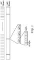
- the created metadata can be transmitted to a receiver together with the A/V streams in the appropriate multiplex, an example as shown in Figure 3 .
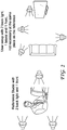
- the metadata are then decoded by the receivers, some adaptation is performed if necessary, and the light effect is rendered by the receiver lights, an example as shown in Figure 1 .
- the creation setup and the receiver setup can be different, an example as shown in Figure 2 .
- the created data are then included into the gaming representation format as additional information.
- additional information As an example, assuming a representation format similar to XML, dedicated messages are created, as described below, and played back by the gaming platform.
- the emission characteristics of the light sources are summarized into a straightforward descriptor, such as luminance L along with a and b chromaticity coordinates (i.e. a single tristimulus value in the CIELab color space).
- a straightforward descriptor such as luminance L along with a and b chromaticity coordinates (i.e. a single tristimulus value in the CIELab color space).
- they can be encoded in various other formats, such as RGB for example.
- the Light i effect is created using an editing tool to add, at a given time during a particular media content, such as a movie, show, or cartoon, for example.
- the light effect can comprise a color with its duration and speed, for example, an example as shown in Figure 4 .
- the synchronization is assumed by a network layer (for example IP, MPEG-2 TS, mp4 file.7) that includes appropriate timestamps to the A/V/L (audio/video/light) data packets, an example as shown in Figure 3 .
- the codeword as shown in Figure 5 , has a configuration of:
- the Light i effect is created using an editing tool to add, at a given action and place during the game, a color with its duration and speed, an example as shown in Figure 4 .
- the synchronization is assumed by the game engine renderer.
- the XML message can be, without loss of generality, for example:
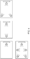
- Figure 6 shows several example configurations of light placement in a room. If multiple light sources are used in the studio, then their number and position in a squared room can be transmitted. Alternatively, the simple mapping shown in Figure 8 can be used, for example. Clockwise order is assumed in this example, starting from front center and looking to front.
- a simple average can be used or more complicated color mapping depending on distance and dominant color.
- the lighting effects for the viewer lights can be a function of the lighting parameters from the reference lighting locations. Other variations are again possible.
- One advantage of at least one of the embodiments is that it enables the director of photography to create special light effects for the viewing environment of the end consumer, for the purpose of enhancing the viewing experience.
- the proposed embodiments specify a full workflow to create, transmit and render those lighting effects, simple and compatible with existing infrastructures and A/V data streams.
- Devices capable of controlling light sources in a home using metadata synchronized with A/V content can use the described embodiments.
- dedicated light codes can be added into the game description language.
- At least one described embodiment proposes to create, distribute and render illumination effects created by movie directors during film creation of post-production.
- the final goal being to increase the immersion for the final viewer.
- the illumination in the grading studio can be characterized by the color of several light sources together with their number and assumed position in the viewing room.
- the color of the light source can be encoded as metadata synchronized with the A/V stream in any transmission (broadcast, OTT, etc.), and could also be embedded on DVDs and Blu-Ray disks.
- the ISO/IEC 23005 standard (aka MPEG-V) can be used to describe such data, but we propose a simplified format inspired by audio multi-channel schemes.
- the recipient (or player) would receive these values, optionally perform some adaptation to fit with the consumer setup (compared to the reference one), and then dynamically control lights/projectors through the consumers' home WIFI, or through any other protocol used to interact with connected lights/projectors to render the light effects.
- Figure 9 shows one embodiment of a method 900 for using embedded information to control lights at a user location.
- the method commences at Start block 901 and control proceeds to block 910 for receiving a content stream.
- Control proceeds from block 910 to block 920 for providing illumination data to lighting at the user location.
- Control then proceeds to block 930 for outputting video data in synchronization with the controlled lighting.
- Block 910 can also comprise demultiplexing to separate the illumination data from the video data, and from any other type of data comprising the content stream.
- Block 920 can also comprise mapping, if necessary, to map the illumination data that is based on a reference lighting setup, typically at the site of a content creator, to the lighting at a user location.
- FIG. 10 shows an apparatus 1000 for using embedded information to control lights at a user location.
- the apparatus comprises a Receiver 1010 of a content stream comprising video and illumination data.
- the illumination data output of Receiver 1010 is in signal connectivity with an input of Lighting Controller 1020.
- Another output of Receiver 1010 is video data information that is typically sent to a display (not shown).
- Lighting Controller 1020 outputs lighting controls on an output port.
- Receiver 1010 can also comprise a demultiplexer for separating the illumination data from the video data, and from any other type of data comprising the content stream.
- Lighting Controller 1020 can also perform mapping, if necessary, to map the illumination data that is based on a reference lighting setup, typically at the site of a content creator, to the lighting at a user location.
- Figure 11 shows a method 1100 of generating a content stream to control lighting at a user location.
- the method commences at Start block 1101 and control proceeds to block 1110 for generating illumination data from lighting controls.
- the lighting controls can originate through manually operated lighting operations, through computer generated controls, or elsewhere.
- Control then proceeds from block 1110 to block 1120 for providing a content stream of video and illumination data, which are either synchronized or contain information that allows synchronization at a receiver.
- Other types of data such as audio or gaming information, can be in the content stream.
- FIG. 12 shows an apparatus 1200 for generating a content stream to control lighting at a user location.
- the apparatus comprises Controller 1210 that receives lighting controls on an input port.
- the lighting controls can originate through manually operated lighting operations, through computer generated controls, or elsewhere.
- Controller 1210 sends illumination from an output port, which is in signal connectivity with a first input of Processor 1220.
- Processor 1220 receives video data on a second input port.
- Processor 1220 then outputs a content stream on an output port comprising the illumination data and video data, which are either synchronized or contain information that allows synchronization at a receiver.
- Other types of data such as audio or gaming information, can be in the content stream as well.
- processor or “controller” should not be construed to refer exclusively to hardware capable of executing software, and may implicitly include, without limitation, digital signal processor (“DSP”) hardware, read-only memory (“ROM”) for storing software, random access memory (“RAM”), and non-volatile storage.
- DSP digital signal processor
- ROM read-only memory
- RAM random access memory
Landscapes
- Engineering & Computer Science (AREA)
- Multimedia (AREA)
- Signal Processing (AREA)
- Physics & Mathematics (AREA)
- Optics & Photonics (AREA)
- Circuit Arrangement For Electric Light Sources In General (AREA)
Description
- The present principles relate to the specification of a format and system for color illumination creation, distribution and rendering, synchronized with audio/video content.
- Consumers generally watch television or movies, or play games at home in a viewing environment that is not well controlled. The viewing environment, the room where the consumer and the display are located, is typically illuminated by daylight and/or a combination of tungsten, fluorescent and LED light sources. This leads to a great variability of viewing environments, none of which are ideal for viewing content.
- Human visual perception strongly depends on how it adapts to its environment.
- The perception of content seen on a television, for instance, therefore depends strongly on how the room is illuminated. As a consequence, while directors of photography have control over the content that they distribute, they do not have control over how this content is perceived. Replicating the viewing conditions of the grading studio would help solve this problem, either by designing a room to match the grading studio, or by communicating static lighting.
-
US 2015/0305117 A1 discloses a method for creating in a display space an ambience lighting effect. - These and other drawbacks and disadvantages of the prior art are addressed by methods and devices according to the appended claims
- According to a general aspect not according to the current invention described herein, there is provided a method comprising: receiving a content stream comprising video and illumination data, wherein said illumination data comprises luminance and chrominance information synchronized to said video data and based on a reference lighting setup; providing said illumination data to control lighting at location of a receiver by mapping the illumination data to the lights at said receiver location; and outputting the video data for display in synchronization with lighting at the receiver location.
- According to another general aspect not according to the current invention described herein, there is provided an apparatus. The apparatus comprises a receiver of a content stream comprising video and illumination data, wherein said illumination data comprises luminance and chrominance information synchronized to said video data and based on a reference lighting setup, and a lighting controller to control lights at location of said receiver by mapping the illumination data to lighting at said receiver location in synchronization with the video data that is output for display.
- According to another general aspect not according to the current invention described herein, there is provided another method. The method comprises generating illumination data comprising luminance and chrominance information from lighting controls based on a reference lighting setup, and providing a content stream comprising video data and said illumination data, wherein said illumination data comprises luminance and chrominance information synchronized to said video data and based on a reference lighting setup.
- According to another general aspect not according to the current invention described herein, there is provided an apparatus. The apparatus comprises a controller to generate illumination data comprising luminance and chrominance information from lighting controls based on a reference lighting setup, and a processor to provide a content stream comprising video data and said illumination data, wherein said illumination data comprises luminance and chrominance information synchronized to the video data.
- Features and advantages of the present principles will become apparent from the following detailed description of exemplary embodiments, which is to be read in connection with the accompanying drawings.
-
-
Figure 1 shows one example of the light effect rendered by receiver lights. -
Figure 2 shows an example of creation setup and the receiver setup that can be different. -
Figure 3 shows one embodiment of the created metadata transmitted to a receiver together with the A/V streams in a multiplex. -
Figure 4 shows an example of specification of a light effect, comprising a color with duration and speed. -
Figure 5 shows an example configuration of a codeword describing illumination effects. -
Figure 6 shows several example configurations of light placement in a room. -
Figure 7 shows an example of an editing tool to create lighting effects synchronized with audio/video content. -
Figure 8 shows an example of a simple mapping of a lighting configuration. -
Figure 9 shows an example embodiment of a method for receiving a content stream to control lighting at a user location. -
Figure 10 shows an example embodiment of an apparatus for receiving a content stream to control lighting at a user location. -
Figure 11 shows an example embodiment of a method for generating a content stream to control lighting at a user location. -
Figure 12 shows an example embodiment of an apparatus for generating a content stream to control lighting at a user location. - An approach is described for creating room illumination effects based on a defined reference setup, encoding those effects using metadata and rendering this information using a user illumination setup in a home, movie theater, or other environment.
- Room illumination may additionally be used creatively to increase the level of immersion. Generally lighting effects are extracted at the receiver side from the content using some computer vision tools. The PHILIPS Ambilight TV set is an example of such technology currently on the market. It illuminates a small wall area behind the television with colored light derived from the content displayed simultaneously. Projectors may also be used to project on walls and objects surrounding the television, as demonstrated by Microsoft's IllumiRoom. An alternative system analyzes the video footage to drive external lights that are placed in strategic places in the room.
- Another approach describes a system for capturing illumination in one room, and reproducing it using programmable light sources in a different room.
- The ISO/IEC 23005 standard (aka MPEG-V) proposed a format to represent and transmit Media Context and Control information. It typically includes means to represent and encode lighting information. However it does not specify the workflow to create and render those effects and to use this format. The MPEG-V format itself is based on XML (Extensible Markup Language) and is quite complex since it was done to be generic and apply to any type of system. In addition it is not said how to "map" the created effects to the rendering setup.
- None of the aforementioned systems and solutions allow directors of photography to exert creative/dynamic control over the consumers' viewing environments, and thereby actively enhance the viewer's immersive experience. A key difference from existing solutions is that the embodiments herein described allow remote authoring of dynamic room illumination, synchronize this information with A/V (audio/video) content, and reproduce the authored room illumination along with A/V playback in a consumer's home. Similar principles can also apply to creating light effects associated with games. One difference is the interactivity with gaming. Thus the special effects are created during the game design depending on actions and places, and the gaming receiver plays back the effects when appropriate during the game. This can be in response to something a player does, a score value, or a situation or event that occurs in the game, for example.
- The described embodiments attempt to solve all these issues with the specification of a reference setup, the specification of a simple metadata format to transmit the light effects information, an associated coding scheme to be synchronized with A/V streams, and the specification of an approach to "map/translate/adapt" the created effects to the user setup.
- To this end, an example embodiment of one workflow is assumed as follows.
- The post-production studio is fitted with lights for which the emission characteristics and position are known. The effects are created using a dedicated editing tool, an example as shown in
Figure 7 . Then the created metadata can be transmitted to a receiver together with the A/V streams in the appropriate multiplex, an example as shown inFigure 3 . The metadata are then decoded by the receivers, some adaptation is performed if necessary, and the light effect is rendered by the receiver lights, an example as shown inFigure 1 . The creation setup and the receiver setup can be different, an example as shown inFigure 2 . - The same concept can be included into gaming design platform and editing tools.
- The created data are then included into the gaming representation format as additional information. As an example, assuming a representation format similar to XML, dedicated messages are created, as described below, and played back by the gaming platform.
- The emission characteristics of the light sources are summarized into a straightforward descriptor, such as luminance L along with a and b chromaticity coordinates (i.e. a single tristimulus value in the CIELab color space). Alternatively, they can be encoded in various other formats, such as RGB for example.
- The Lighti effect is created using an editing tool to add, at a given time during a particular media content, such as a movie, show, or cartoon, for example. The light effect can comprise a color with its duration and speed, for example, an example as shown in
Figure 4 . The synchronization is assumed by a network layer (for example IP, MPEG-2 TS, mp4 file....) that includes appropriate timestamps to the A/V/L (audio/video/light) data packets, an example as shown inFigure 3 . The codeword, as shown inFigure 5 , has a configuration of: - 1) three 32 bit fields of information for the color information Lab
- 2) A 32 float field for the duration d of light
- 3) A 32 float field for parameters α describing the speed to move from one light level to another one. This can be defined as a linear function, and in terms of seconds, for example.
- The Lighti effect is created using an editing tool to add, at a given action and place during the game, a color with its duration and speed, an example as shown in
Figure 4 . The synchronization is assumed by the game engine renderer. The XML message can be, without loss of generality, for example:
                       <Iigheffects ID=01>
                             <color>{rgb , 0.2,0.1,0.8}</color>
                             <duration>10.3</duration>
                             <speed>0.5</speed>
                       </lighteffects>
Claims (10)
- A method for displaying video data at a display location, comprising:obtaining a bitstream comprising video and illumination data, wherein said illumination data comprise luminance and chrominance information synchronized to said video data and based on a reference lighting setup;controlling lighting at the display location by mapping the illumination data to the lighting at said display location in synchronization with the video data that are output for display; and characterised in that the illumination data are represented by at least one bitstream portion, the at least one bitstream portion comprising three 32 bit fields (L, a, b) of information for a color information for the lighting, a 32 float field for a duration (d) of the lighting, and a 32 float field for parameters (α) describing a speed to move from one lighting level to another one.
- An apparatus for displaying video data at a display location, comprising:a receiver of a bitstream comprising video and illumination data, wherein said illumination data comprise luminance and chrominance information synchronized to said video data and based on a reference lighting setup; and,a lighting controller configured to control lighting at said display location by mapping the illumination data to the lighting at said display location in synchronization with the video data that are output for display, and characterised in that the illumination data are represented by at least one bitstream portion, the at least one bitstream portion comprising three 32 bit fields (L, a, b) of information for a color information for the lighting, a 32 float field for a duration (d) of the lighting and a 32 float field for parameters (α) describing a speed to move from one lighting level to another one.
- The method of Claim 1 or the apparatus of Claim 2, wherein audio data is included with said illumination data and said video data in the bitstream and controlling is also based on said audio data.
- The method or apparatus of Claim 3, wherein the audio information is part of a gaming environment.
- A method, comprising:generating illumination data comprising luminance and chrominance information from lighting controls based on a reference lighting setup, wherein said illumination data is synchronized to video data;providing a bitstream comprising said video data and said illumination data, characterised in that the illumination data are represented by at least one bitstream portion, the at least one bitstream portion comprising three 32 bit fields (L, a, b) of information for a color information for the lighting, a 32 float field for a duration (d) of the lighting, and a 32 float field for parameters (α) describing a speed to move from one lighting level to another one, .
- An apparatus, comprising:a controller to generate illumination data comprising luminance and chrominance information from lighting controls based on a reference lighting setup, wherein said illumination data is synchronized to video data;a processor configured to provide a bitstream comprising said video data and said illumination data, characterised in that the illumination data are represented by at least one bitstream portion, the at least one bitstream portion comprising three 32 bit fields (L, a, b) of information for a color information for the lighting, a 32 float field for a duration (d) of the lighting, and a 32 float field for parameters (α) describing a speed to move from one lighting level to another one.
- The method of Claim 5 or the apparatus of Claim 6, wherein other types of data are included in said bitstream and wherein said illumination data are synchronized also to at least one of the other types of data.
- The method or apparatus of Claim 7, wherein the other type of data comprises audio information.
- A non-transitory computer readable medium containing instructions which, when executed by a computer, cause the computer to carry out the method of any one of claims 1, 3-5 and 7 to 8.
- A computer program product comprising instructions which, when the program is executed by a computer, cause the computer to carry out the method of any one of claims 1, 3-5 and 7 to 8.
Applications Claiming Priority (2)
| Application Number | Priority Date | Filing Date | Title |
|---|---|---|---|
| EP16306579.0A EP3331325A1 (en) | 2016-11-30 | 2016-11-30 | Method and apparatus for creating, distributing and dynamically reproducing room illumination effects |
| PCT/EP2017/080626 WO2018099898A1 (en) | 2016-11-30 | 2017-11-28 | Method and apparatus for creating, distributing and dynamically reproducing room illumination effects |
Publications (2)
| Publication Number | Publication Date |
|---|---|
| EP3549407A1 EP3549407A1 (en) | 2019-10-09 |
| EP3549407B1 true EP3549407B1 (en) | 2022-01-05 |
Family
ID=57681502
Family Applications (2)
| Application Number | Title | Priority Date | Filing Date |
|---|---|---|---|
| EP16306579.0A Withdrawn EP3331325A1 (en) | 2016-11-30 | 2016-11-30 | Method and apparatus for creating, distributing and dynamically reproducing room illumination effects |
| EP17808056.0A Not-in-force EP3549407B1 (en) | 2016-11-30 | 2017-11-28 | Method and apparatus for creating, distributing and dynamically reproducing room illumination effects |
Family Applications Before (1)
| Application Number | Title | Priority Date | Filing Date |
|---|---|---|---|
| EP16306579.0A Withdrawn EP3331325A1 (en) | 2016-11-30 | 2016-11-30 | Method and apparatus for creating, distributing and dynamically reproducing room illumination effects |
Country Status (3)
| Country | Link |
|---|---|
| US (1) | US11184581B2 (en) |
| EP (2) | EP3331325A1 (en) |
| WO (1) | WO2018099898A1 (en) |
Families Citing this family (4)
| Publication number | Priority date | Publication date | Assignee | Title |
|---|---|---|---|---|
| WO2019233800A1 (en) * | 2018-06-08 | 2019-12-12 | Signify Holding B.V. | Adjusting parameters of light effects specified in a light script |
| US12250421B2 (en) * | 2019-11-07 | 2025-03-11 | Comcast Cable Communications, Llc | Device synchronization for audiovisual content |
| WO2022122437A1 (en) * | 2020-12-08 | 2022-06-16 | Signify Holding B.V. | Determining light effects in dependence on whether an overlay is likely displayed on top of video content |
| WO2024200092A1 (en) * | 2023-03-24 | 2024-10-03 | Signify Holding B.V. | Control device for rendering downsized lighting-effect routine |
Family Cites Families (16)
| Publication number | Priority date | Publication date | Assignee | Title |
|---|---|---|---|---|
| JP4950988B2 (en) | 2006-04-21 | 2012-06-13 | シャープ株式会社 | Data transmission device, data transmission method, viewing environment control device, viewing environment control system, and viewing environment control method |
| RU2468401C2 (en) * | 2006-12-08 | 2012-11-27 | Конинклейке Филипс Электроникс Н.В. | Ambient illumination |
| WO2008084677A1 (en) * | 2006-12-28 | 2008-07-17 | Sharp Kabushiki Kaisha | Transmission device, view environment control device, and view environment control system |
| WO2011159617A1 (en) | 2010-06-15 | 2011-12-22 | Dolby Laboratories Licensing Corporation | Encoding, distributing and displaying video data containing customized video content versions |
| TWI516169B (en) | 2011-07-20 | 2016-01-01 | 瑞軒科技股份有限公司 | Video system and control method thereof |
| US20130147395A1 (en) | 2011-12-07 | 2013-06-13 | Comcast Cable Communications, Llc | Dynamic Ambient Lighting |
| US8928812B2 (en) | 2012-10-17 | 2015-01-06 | Sony Corporation | Ambient light effects based on video via home automation |
| EP2926626B1 (en) * | 2012-11-27 | 2020-01-08 | Signify Holding B.V. | Method for creating ambience lighting effect based on data derived from stage performance |
| US9432612B2 (en) | 2013-09-20 | 2016-08-30 | Echostar Technologies L.L.C. | Environmental adjustments to perceive true content |
| US20150117830A1 (en) * | 2013-10-30 | 2015-04-30 | Google Inc. | Light tracks for media content |
| CN103795896B (en) | 2014-02-25 | 2016-10-05 | 冠捷显示科技(厦门)有限公司 | A kind of display device ambient light control system |
| EP2914067B1 (en) | 2014-02-27 | 2018-04-25 | Airbus Operations GmbH | Lighting system and method for controlling a lighting system |
| WO2016080754A1 (en) | 2014-11-19 | 2016-05-26 | 엘지전자 주식회사 | Method and apparatus for transceiving broadcast signal for viewing environment adjustment |
| US10368105B2 (en) | 2015-06-09 | 2019-07-30 | Microsoft Technology Licensing, Llc | Metadata describing nominal lighting conditions of a reference viewing environment for video playback |
| AU2015207825A1 (en) | 2015-07-28 | 2017-02-16 | Canon Kabushiki Kaisha | Method, apparatus and system for encoding video data for selected viewing conditions |
| WO2017182365A1 (en) * | 2016-04-22 | 2017-10-26 | Philips Lighting Holding B.V. | Controlling a lighting system |
-
2016
- 2016-11-30 EP EP16306579.0A patent/EP3331325A1/en not_active Withdrawn
-
2017
- 2017-11-28 US US16/464,419 patent/US11184581B2/en active Active
- 2017-11-28 WO PCT/EP2017/080626 patent/WO2018099898A1/en not_active Ceased
- 2017-11-28 EP EP17808056.0A patent/EP3549407B1/en not_active Not-in-force
Non-Patent Citations (1)
| Title |
|---|
| None * |
Also Published As
| Publication number | Publication date |
|---|---|
| EP3331325A1 (en) | 2018-06-06 |
| EP3549407A1 (en) | 2019-10-09 |
| US11184581B2 (en) | 2021-11-23 |
| WO2018099898A1 (en) | 2018-06-07 |
| US20200382742A1 (en) | 2020-12-03 |
Similar Documents
| Publication | Publication Date | Title |
|---|---|---|
| JP6566271B2 (en) | Transmission method and playback apparatus | |
| JP5575659B2 (en) | 3D mode selection mechanism for video playback | |
| CN111836047B (en) | Display device | |
| JP6419807B2 (en) | HDR metadata transfer | |
| CA2747106C (en) | Method and device for overlaying 3d graphics over 3d video | |
| US20110188832A1 (en) | Method and device for realising sensory effects | |
| US9445034B2 (en) | Method and apparatus for processing video image | |
| US11184581B2 (en) | Method and apparatus for creating, distributing and dynamically reproducing room illumination effects | |
| US20110293240A1 (en) | Method and system for transmitting over a video interface and for compositing 3d video and 3d overlays | |
| JP2017184249A (en) | Display device, display method, and computer program | |
| WO2010007988A1 (en) | Data transmission device, method for transmitting data, audio-visual environment control device, audio-visual environment control system, and method for controlling audio-visual environment | |
| US20120293619A1 (en) | Generating a 3d video signal | |
| WO2009027923A1 (en) | Conveying auxiliary information in a multiplexed stream | |
| US12206954B2 (en) | Apparatus and method for providing audio description content | |
| KR101675119B1 (en) | Method and apparatus for generating datastream to marking user recognition information indicating three-dimensional display on screen, method and appartus for three-dimensional display using the same datastream | |
| CN103262547B (en) | The transfer of 3D rendering data | |
| US12538000B2 (en) | Apparatus and method for providing audio description content | |
| US20260136076A1 (en) | Apparatus and method for providing audio description content | |
| JP2009060541A (en) | Data transmission device, data transmission method, viewing environment control device, and viewing environment control method | |
| JP6751893B2 (en) | Reproduction method, reproduction device, display method and display device | |
| Zink | Blu-Ray 3D™ |
Legal Events
| Date | Code | Title | Description |
|---|---|---|---|
| STAA | Information on the status of an ep patent application or granted ep patent |
Free format text: STATUS: UNKNOWN |
|
| STAA | Information on the status of an ep patent application or granted ep patent |
Free format text: STATUS: THE INTERNATIONAL PUBLICATION HAS BEEN MADE |
|
| PUAI | Public reference made under article 153(3) epc to a published international application that has entered the european phase |
Free format text: ORIGINAL CODE: 0009012 |
|
| STAA | Information on the status of an ep patent application or granted ep patent |
Free format text: STATUS: REQUEST FOR EXAMINATION WAS MADE |
|
| 17P | Request for examination filed |
Effective date: 20190523 |
|
| AK | Designated contracting states |
Kind code of ref document: A1 Designated state(s): AL AT BE BG CH CY CZ DE DK EE ES FI FR GB GR HR HU IE IS IT LI LT LU LV MC MK MT NL NO PL PT RO RS SE SI SK SM TR |
|
| AX | Request for extension of the european patent |
Extension state: BA ME |
|
| DAV | Request for validation of the european patent (deleted) | ||
| DAX | Request for extension of the european patent (deleted) | ||
| STAA | Information on the status of an ep patent application or granted ep patent |
Free format text: STATUS: EXAMINATION IS IN PROGRESS |
|
| 17Q | First examination report despatched |
Effective date: 20200423 |
|
| REG | Reference to a national code |
Ref country code: DE Ref legal event code: R079 Ref document number: 602017051961 Country of ref document: DE Free format text: PREVIOUS MAIN CLASS: H05B0037020000 Ipc: H05B0047155000 |
|
| GRAP | Despatch of communication of intention to grant a patent |
Free format text: ORIGINAL CODE: EPIDOSNIGR1 |
|
| STAA | Information on the status of an ep patent application or granted ep patent |
Free format text: STATUS: GRANT OF PATENT IS INTENDED |
|
| RAP1 | Party data changed (applicant data changed or rights of an application transferred) |
Owner name: INTERDIGITAL MADISON PATENT HOLDINGS, SAS |
|
| RIC1 | Information provided on ipc code assigned before grant |
Ipc: H05B 47/155 20200101AFI20210624BHEP |
|
| INTG | Intention to grant announced |
Effective date: 20210716 |
|
| GRAS | Grant fee paid |
Free format text: ORIGINAL CODE: EPIDOSNIGR3 |
|
| GRAA | (expected) grant |
Free format text: ORIGINAL CODE: 0009210 |
|
| STAA | Information on the status of an ep patent application or granted ep patent |
Free format text: STATUS: THE PATENT HAS BEEN GRANTED |
|
| AK | Designated contracting states |
Kind code of ref document: B1 Designated state(s): AL AT BE BG CH CY CZ DE DK EE ES FI FR GB GR HR HU IE IS IT LI LT LU LV MC MK MT NL NO PL PT RO RS SE SI SK SM TR |
|
| REG | Reference to a national code |
Ref country code: GB Ref legal event code: FG4D |
|
| REG | Reference to a national code |
Ref country code: CH Ref legal event code: EP |
|
| REG | Reference to a national code |
Ref country code: AT Ref legal event code: REF Ref document number: 1461759 Country of ref document: AT Kind code of ref document: T Effective date: 20220115 |
|
| REG | Reference to a national code |
Ref country code: DE Ref legal event code: R096 Ref document number: 602017051961 Country of ref document: DE |
|
| REG | Reference to a national code |
Ref country code: IE Ref legal event code: FG4D |
|
| REG | Reference to a national code |
Ref country code: NL Ref legal event code: FP |
|
| REG | Reference to a national code |
Ref country code: LT Ref legal event code: MG9D |
|
| REG | Reference to a national code |
Ref country code: AT Ref legal event code: MK05 Ref document number: 1461759 Country of ref document: AT Kind code of ref document: T Effective date: 20220105 |
|
| PG25 | Lapsed in a contracting state [announced via postgrant information from national office to epo] |
Ref country code: SE Free format text: LAPSE BECAUSE OF FAILURE TO SUBMIT A TRANSLATION OF THE DESCRIPTION OR TO PAY THE FEE WITHIN THE PRESCRIBED TIME-LIMIT Effective date: 20220105 Ref country code: RS Free format text: LAPSE BECAUSE OF FAILURE TO SUBMIT A TRANSLATION OF THE DESCRIPTION OR TO PAY THE FEE WITHIN THE PRESCRIBED TIME-LIMIT Effective date: 20220105 Ref country code: PT Free format text: LAPSE BECAUSE OF FAILURE TO SUBMIT A TRANSLATION OF THE DESCRIPTION OR TO PAY THE FEE WITHIN THE PRESCRIBED TIME-LIMIT Effective date: 20220505 Ref country code: NO Free format text: LAPSE BECAUSE OF FAILURE TO SUBMIT A TRANSLATION OF THE DESCRIPTION OR TO PAY THE FEE WITHIN THE PRESCRIBED TIME-LIMIT Effective date: 20220405 Ref country code: LT Free format text: LAPSE BECAUSE OF FAILURE TO SUBMIT A TRANSLATION OF THE DESCRIPTION OR TO PAY THE FEE WITHIN THE PRESCRIBED TIME-LIMIT Effective date: 20220105 Ref country code: HR Free format text: LAPSE BECAUSE OF FAILURE TO SUBMIT A TRANSLATION OF THE DESCRIPTION OR TO PAY THE FEE WITHIN THE PRESCRIBED TIME-LIMIT Effective date: 20220105 Ref country code: ES Free format text: LAPSE BECAUSE OF FAILURE TO SUBMIT A TRANSLATION OF THE DESCRIPTION OR TO PAY THE FEE WITHIN THE PRESCRIBED TIME-LIMIT Effective date: 20220105 Ref country code: BG Free format text: LAPSE BECAUSE OF FAILURE TO SUBMIT A TRANSLATION OF THE DESCRIPTION OR TO PAY THE FEE WITHIN THE PRESCRIBED TIME-LIMIT Effective date: 20220405 |
|
| PG25 | Lapsed in a contracting state [announced via postgrant information from national office to epo] |
Ref country code: PL Free format text: LAPSE BECAUSE OF FAILURE TO SUBMIT A TRANSLATION OF THE DESCRIPTION OR TO PAY THE FEE WITHIN THE PRESCRIBED TIME-LIMIT Effective date: 20220105 Ref country code: LV Free format text: LAPSE BECAUSE OF FAILURE TO SUBMIT A TRANSLATION OF THE DESCRIPTION OR TO PAY THE FEE WITHIN THE PRESCRIBED TIME-LIMIT Effective date: 20220105 Ref country code: GR Free format text: LAPSE BECAUSE OF FAILURE TO SUBMIT A TRANSLATION OF THE DESCRIPTION OR TO PAY THE FEE WITHIN THE PRESCRIBED TIME-LIMIT Effective date: 20220406 Ref country code: FI Free format text: LAPSE BECAUSE OF FAILURE TO SUBMIT A TRANSLATION OF THE DESCRIPTION OR TO PAY THE FEE WITHIN THE PRESCRIBED TIME-LIMIT Effective date: 20220105 Ref country code: AT Free format text: LAPSE BECAUSE OF FAILURE TO SUBMIT A TRANSLATION OF THE DESCRIPTION OR TO PAY THE FEE WITHIN THE PRESCRIBED TIME-LIMIT Effective date: 20220105 |
|
| PG25 | Lapsed in a contracting state [announced via postgrant information from national office to epo] |
Ref country code: IS Free format text: LAPSE BECAUSE OF FAILURE TO SUBMIT A TRANSLATION OF THE DESCRIPTION OR TO PAY THE FEE WITHIN THE PRESCRIBED TIME-LIMIT Effective date: 20220505 |
|
| REG | Reference to a national code |
Ref country code: DE Ref legal event code: R097 Ref document number: 602017051961 Country of ref document: DE |
|
| PG25 | Lapsed in a contracting state [announced via postgrant information from national office to epo] |
Ref country code: SM Free format text: LAPSE BECAUSE OF FAILURE TO SUBMIT A TRANSLATION OF THE DESCRIPTION OR TO PAY THE FEE WITHIN THE PRESCRIBED TIME-LIMIT Effective date: 20220105 Ref country code: SK Free format text: LAPSE BECAUSE OF FAILURE TO SUBMIT A TRANSLATION OF THE DESCRIPTION OR TO PAY THE FEE WITHIN THE PRESCRIBED TIME-LIMIT Effective date: 20220105 Ref country code: RO Free format text: LAPSE BECAUSE OF FAILURE TO SUBMIT A TRANSLATION OF THE DESCRIPTION OR TO PAY THE FEE WITHIN THE PRESCRIBED TIME-LIMIT Effective date: 20220105 Ref country code: EE Free format text: LAPSE BECAUSE OF FAILURE TO SUBMIT A TRANSLATION OF THE DESCRIPTION OR TO PAY THE FEE WITHIN THE PRESCRIBED TIME-LIMIT Effective date: 20220105 Ref country code: DK Free format text: LAPSE BECAUSE OF FAILURE TO SUBMIT A TRANSLATION OF THE DESCRIPTION OR TO PAY THE FEE WITHIN THE PRESCRIBED TIME-LIMIT Effective date: 20220105 Ref country code: CZ Free format text: LAPSE BECAUSE OF FAILURE TO SUBMIT A TRANSLATION OF THE DESCRIPTION OR TO PAY THE FEE WITHIN THE PRESCRIBED TIME-LIMIT Effective date: 20220105 |
|
| RAP4 | Party data changed (patent owner data changed or rights of a patent transferred) |
Owner name: INTERDIGITAL MADISON PATENT HOLDINGS, SAS |
|
| PLBE | No opposition filed within time limit |
Free format text: ORIGINAL CODE: 0009261 |
|
| STAA | Information on the status of an ep patent application or granted ep patent |
Free format text: STATUS: NO OPPOSITION FILED WITHIN TIME LIMIT |
|
| PG25 | Lapsed in a contracting state [announced via postgrant information from national office to epo] |
Ref country code: AL Free format text: LAPSE BECAUSE OF FAILURE TO SUBMIT A TRANSLATION OF THE DESCRIPTION OR TO PAY THE FEE WITHIN THE PRESCRIBED TIME-LIMIT Effective date: 20220105 |
|
| 26N | No opposition filed |
Effective date: 20221006 |
|
| PGFP | Annual fee paid to national office [announced via postgrant information from national office to epo] |
Ref country code: NL Payment date: 20221124 Year of fee payment: 6 Ref country code: GB Payment date: 20221122 Year of fee payment: 6 Ref country code: FR Payment date: 20221122 Year of fee payment: 6 Ref country code: DE Payment date: 20220527 Year of fee payment: 6 |
|
| PG25 | Lapsed in a contracting state [announced via postgrant information from national office to epo] |
Ref country code: SI Free format text: LAPSE BECAUSE OF FAILURE TO SUBMIT A TRANSLATION OF THE DESCRIPTION OR TO PAY THE FEE WITHIN THE PRESCRIBED TIME-LIMIT Effective date: 20220105 |
|
| P01 | Opt-out of the competence of the unified patent court (upc) registered |
Effective date: 20230514 |
|
| PG25 | Lapsed in a contracting state [announced via postgrant information from national office to epo] |
Ref country code: MC Free format text: LAPSE BECAUSE OF FAILURE TO SUBMIT A TRANSLATION OF THE DESCRIPTION OR TO PAY THE FEE WITHIN THE PRESCRIBED TIME-LIMIT Effective date: 20220105 |
|
| REG | Reference to a national code |
Ref country code: CH Ref legal event code: PL |
|
| REG | Reference to a national code |
Ref country code: BE Ref legal event code: MM Effective date: 20221130 |
|
| PG25 | Lapsed in a contracting state [announced via postgrant information from national office to epo] |
Ref country code: LI Free format text: LAPSE BECAUSE OF NON-PAYMENT OF DUE FEES Effective date: 20221130 Ref country code: IT Free format text: LAPSE BECAUSE OF FAILURE TO SUBMIT A TRANSLATION OF THE DESCRIPTION OR TO PAY THE FEE WITHIN THE PRESCRIBED TIME-LIMIT Effective date: 20220105 Ref country code: CH Free format text: LAPSE BECAUSE OF NON-PAYMENT OF DUE FEES Effective date: 20221130 |
|
| PG25 | Lapsed in a contracting state [announced via postgrant information from national office to epo] |
Ref country code: LU Free format text: LAPSE BECAUSE OF NON-PAYMENT OF DUE FEES Effective date: 20221128 |
|
| PG25 | Lapsed in a contracting state [announced via postgrant information from national office to epo] |
Ref country code: IE Free format text: LAPSE BECAUSE OF NON-PAYMENT OF DUE FEES Effective date: 20221128 |
|
| PG25 | Lapsed in a contracting state [announced via postgrant information from national office to epo] |
Ref country code: BE Free format text: LAPSE BECAUSE OF NON-PAYMENT OF DUE FEES Effective date: 20221130 |
|
| PG25 | Lapsed in a contracting state [announced via postgrant information from national office to epo] |
Ref country code: HU Free format text: LAPSE BECAUSE OF FAILURE TO SUBMIT A TRANSLATION OF THE DESCRIPTION OR TO PAY THE FEE WITHIN THE PRESCRIBED TIME-LIMIT; INVALID AB INITIO Effective date: 20171128 |
|
| PG25 | Lapsed in a contracting state [announced via postgrant information from national office to epo] |
Ref country code: CY Free format text: LAPSE BECAUSE OF FAILURE TO SUBMIT A TRANSLATION OF THE DESCRIPTION OR TO PAY THE FEE WITHIN THE PRESCRIBED TIME-LIMIT Effective date: 20220105 |
|
| PG25 | Lapsed in a contracting state [announced via postgrant information from national office to epo] |
Ref country code: MK Free format text: LAPSE BECAUSE OF FAILURE TO SUBMIT A TRANSLATION OF THE DESCRIPTION OR TO PAY THE FEE WITHIN THE PRESCRIBED TIME-LIMIT Effective date: 20220105 |
|
| REG | Reference to a national code |
Ref country code: DE Ref legal event code: R119 Ref document number: 602017051961 Country of ref document: DE |
|
| PG25 | Lapsed in a contracting state [announced via postgrant information from national office to epo] |
Ref country code: TR Free format text: LAPSE BECAUSE OF FAILURE TO SUBMIT A TRANSLATION OF THE DESCRIPTION OR TO PAY THE FEE WITHIN THE PRESCRIBED TIME-LIMIT Effective date: 20220105 |
|
| REG | Reference to a national code |
Ref country code: NL Ref legal event code: MM Effective date: 20231201 |
|
| GBPC | Gb: european patent ceased through non-payment of renewal fee |
Effective date: 20231128 |
|
| PG25 | Lapsed in a contracting state [announced via postgrant information from national office to epo] |
Ref country code: NL Free format text: LAPSE BECAUSE OF NON-PAYMENT OF DUE FEES Effective date: 20231201 |
|
| PG25 | Lapsed in a contracting state [announced via postgrant information from national office to epo] |
Ref country code: NL Free format text: LAPSE BECAUSE OF NON-PAYMENT OF DUE FEES Effective date: 20231201 Ref country code: MT Free format text: LAPSE BECAUSE OF FAILURE TO SUBMIT A TRANSLATION OF THE DESCRIPTION OR TO PAY THE FEE WITHIN THE PRESCRIBED TIME-LIMIT Effective date: 20220105 |
|
| PG25 | Lapsed in a contracting state [announced via postgrant information from national office to epo] |
Ref country code: DE Free format text: LAPSE BECAUSE OF NON-PAYMENT OF DUE FEES Effective date: 20240601 |
|
| PG25 | Lapsed in a contracting state [announced via postgrant information from national office to epo] |
Ref country code: GB Free format text: LAPSE BECAUSE OF NON-PAYMENT OF DUE FEES Effective date: 20231128 |
|
| PG25 | Lapsed in a contracting state [announced via postgrant information from national office to epo] |
Ref country code: FR Free format text: LAPSE BECAUSE OF NON-PAYMENT OF DUE FEES Effective date: 20231130 |
|
| PG25 | Lapsed in a contracting state [announced via postgrant information from national office to epo] |
Ref country code: GB Free format text: LAPSE BECAUSE OF NON-PAYMENT OF DUE FEES Effective date: 20231128 Ref country code: FR Free format text: LAPSE BECAUSE OF NON-PAYMENT OF DUE FEES Effective date: 20231130 Ref country code: DE Free format text: LAPSE BECAUSE OF NON-PAYMENT OF DUE FEES Effective date: 20240601 |