EP3549128B1 - Cushioning element with tuned absorber - Google Patents
Cushioning element with tuned absorber Download PDFInfo
- Publication number
- EP3549128B1 EP3549128B1 EP17817186.4A EP17817186A EP3549128B1 EP 3549128 B1 EP3549128 B1 EP 3549128B1 EP 17817186 A EP17817186 A EP 17817186A EP 3549128 B1 EP3549128 B1 EP 3549128B1
- Authority
- EP
- European Patent Office
- Prior art keywords
- tuned
- cushioning element
- predetermined frequency
- frequency
- assembly
- Prior art date
- Legal status (The legal status is an assumption and is not a legal conclusion. Google has not performed a legal analysis and makes no representation as to the accuracy of the status listed.)
- Active
Links
Images


Classifications
-
- G—PHYSICS
- G10—MUSICAL INSTRUMENTS; ACOUSTICS
- G10K—SOUND-PRODUCING DEVICES; METHODS OR DEVICES FOR PROTECTING AGAINST, OR FOR DAMPING, NOISE OR OTHER ACOUSTIC WAVES IN GENERAL; ACOUSTICS NOT OTHERWISE PROVIDED FOR
- G10K11/00—Methods or devices for transmitting, conducting or directing sound in general; Methods or devices for protecting against, or for damping, noise or other acoustic waves in general
- G10K11/16—Methods or devices for protecting against, or for damping, noise or other acoustic waves in general
- G10K11/162—Selection of materials
- G10K11/168—Plural layers of different materials, e.g. sandwiches
-
- B—PERFORMING OPERATIONS; TRANSPORTING
- B60—VEHICLES IN GENERAL
- B60N—SEATS SPECIALLY ADAPTED FOR VEHICLES; VEHICLE PASSENGER ACCOMMODATION NOT OTHERWISE PROVIDED FOR
- B60N2/00—Seats specially adapted for vehicles; Arrangement or mounting of seats in vehicles
- B60N2/70—Upholstery springs ; Upholstery
-
- B—PERFORMING OPERATIONS; TRANSPORTING
- B64—AIRCRAFT; AVIATION; COSMONAUTICS
- B64D—EQUIPMENT FOR FITTING IN OR TO AIRCRAFT; FLIGHT SUITS; PARACHUTES; ARRANGEMENT OR MOUNTING OF POWER PLANTS OR PROPULSION TRANSMISSIONS IN AIRCRAFT
- B64D11/00—Passenger or crew accommodation; Flight-deck installations not otherwise provided for
- B64D11/06—Arrangements of seats, or adaptations or details specially adapted for aircraft seats
- B64D11/0647—Seats characterised by special upholstery or cushioning features
-
- G—PHYSICS
- G10—MUSICAL INSTRUMENTS; ACOUSTICS
- G10K—SOUND-PRODUCING DEVICES; METHODS OR DEVICES FOR PROTECTING AGAINST, OR FOR DAMPING, NOISE OR OTHER ACOUSTIC WAVES IN GENERAL; ACOUSTICS NOT OTHERWISE PROVIDED FOR
- G10K11/00—Methods or devices for transmitting, conducting or directing sound in general; Methods or devices for protecting against, or for damping, noise or other acoustic waves in general
- G10K11/16—Methods or devices for protecting against, or for damping, noise or other acoustic waves in general
- G10K11/172—Methods or devices for protecting against, or for damping, noise or other acoustic waves in general using resonance effects
Definitions
- the application relates generally to noise absorption and, more particularly, to noise absorption in vehicle cabins such as aircraft cabins.
- Aircraft engines and other rotating components can produce tonal noise which may be an irritant for aircraft passengers.
- Reduction of tonal noise in the aircraft cabin is typically obtained by adding dampening material on the fuselage, for example around and in proximity of the engines.
- Dampening material and structures may be heavy, structurally difficult to implement, and/or require new certification for example when integrated into engine attachments.
- the first predetermined frequency is at least 50 Hz
- a frequency distribution of sound absorption coefficient of the first cushioning element defines a peak at the first predetermined frequency, the peak corresponding to a value of sound absorption coefficient at least 5% above a sound absorption coefficient of the first cushioning element at frequencies adjacent the predetermined frequency.
- the value of sound absorption coefficient at the peak is at least 10% above the sound absorption coefficient of the first cushioning element at frequencies adjacent the first predetermined frequency.
- the first cushioning element includes an outer envelope defining an outer surface of the first cushioning element, the outer envelope being unperforated.
- the first predetermined frequency is at most 100 Hz
- the second predetermined frequency is within a range defined from 100 Hz to 500 Hz.
- the voids are in fluid communication with ports having a smaller cross-sectional area than that of the voids, the voids and ports defining resonators.
- a method of providing noise absorption with an assembly within a cabin of an aircraft having at least one engine comprising determining a first predetermined frequency of at least 20 Hz of an undesirable noise within the cabin, the first predetermined frequency corresponding to a frequency of a tonal noise produced by a low pressure shaft of the at least one engine; determining a second predetermined frequency greater than the first predetermined frequency of an undesirable noise within the cabin, the second predetermined frequency corresponding to a frequency of a tonal noise produced by a high pressure shaft of the at least one engine; configuring a foam core of an internal structure of a first cushioning element of the assembly to define a first tuned absorber tuned to absorb noise at the first predetermined frequency; and configuring a foam core of an internal structure of a second cushioning element of the assembly to define a second tuned absorber tuned to absorb noise at the second predetermined frequency, said first and second predetermined frequencies being in the audible range, the cushioning elements in use being located in the cabin, wherein an
- the aircraft 1 has a fuselage 2 having a fore end at which a cockpit is located, and an aft end supporting a tail assembly, with the cabin generally located between the cockpit and the tail assembly.
- the tail assembly comprises a vertical stabilizer 3 with a rudder, and horizontal stabilizers 4 with elevators.
- the tail assembly has a fuselage-mounted tail, but other configurations may also be used for the aircraft 1, such as cruciform, T-tail, etc.
- Wings 5 project laterally from the fuselage.
- the aircraft 1 has engines 6 supported by the wings 5, although the engines 6 could also be mounted to the fuselage 2.
- the aircraft 1 is shown as a jet-engine aircraft, but may also be a propeller aircraft.
- Rotating or vibrating components of the aircraft 1 can produce tonal noise; cavity resonance may also produce tonal noise.
- Tonal noise can be defined by a noise concentrated in a narrow part of the spectrum or containing a high proportion of energy at a single frequency or within a limited frequency range - as opposed to non-tonal noise which is typically spread over a wide band of frequencies. Tonal noise is generally more noticeable than non-tonal noise of the same level, and accordingly dampening of the tonal noise within the aircraft cabin is desirable.
- Tonal noise generated by rotating components has a predictable frequency which depends on the rotational speed and structure of the rotating components.
- the engine 6 may include low pressure and high pressure rotatable shafts producing tonal noise at different frequencies, these frequencies being affected by the number of blades connected to the shaft, vanes interacting with the flow, etc.
- Other rotatable components may also produce tonal noise, for example gearboxes.
- Other systems may also produce tonal noise, including, but not limited to, hydraulic systems (e.g. hydraulic pumps), electrical transformers, other types of turbines/fans/compressors, pumps, propellers, cavities (cavity resonance), etc.
- the aircraft cabin may contain several cushioning elements, for example seat cushions (seating surface, back rest), sofa cushions (seating surface, back rest), pillows, and, in cabin configurations including sleeping quarters, mattresses.
- the term "cushioning element" as used herein is intended to include any soft and/or padded and/or impact absorbing element designed for comfort of the user for sitting, kneeling or lying thereon, as well as any soft and/or padded and/or impact absorbing element designed to absorb impacts, for example overlaying a structure of the cabin (e.g. cabinet) to prevent injury of users upon impact with such structure.
- Cushioning elements may include padding material (e.g. foam layer(s), foam beads, feathers, unwoven fabric, open or closed cell foam, etc.) and/or springs.
- Cushioning elements may include an outer envelope made of cloth, other types of fabric, natural or synthetic leather, etc.
- tuned absorbers are embedded in cushioning elements to reduce noise at particular frequencies corresponding to the tonal noise generated by the aircraft engine(s).
- the embedded tuned absorber as a whole is not visible from outside of the cushioning element.
- the outer envelope of the cushioning element may be part of the tuned absorber, however the remaining part of the embedded tuned absorber is not visible from outside of the cushioning element, and the apparent outer surface of the outer envelope is preferably not modified to be part of the tuned absorber (e.g., the outer envelope is not perforated).
- the cushioning element may accordingly include the tuned absorber without changing its appearance, i.e. without affecting the esthetic aspect of the cushioning element.
- tuned absorber as used herein is intended to include any apparatus that is tuned to absorb noise at a specific frequency.
- tuned absorbers are provided in the exemplary embodiments described below.
- a cushioning element 10 in accordance with a particular example not forming part of the invention is shown, which may be for example a mattress.
- the cushioning element 10 includes a foam core 12, a plurality of springs 14 extending from the foam core 12, and a top layer 16 of material supported by the springs 14.
- the bottom of the cushioning element 10 may be a mirror image of the layup shown, so that the cushioning element 10 is reversible; alternately, the foam core 12 may define the bottom of the cushioning element 10, or the foam core 12 may be omitted.
- Other variations are possible, including, but not limited to, two or more superimposed layers of springs 14, a layer of springs 14 sandwiched between two foam cores 12, etc.
- An outer layer 18 overlays the top layer 16 and defines an outer surface of the cushioning element 10.
- the outer layer 18 forms or is part of an outer envelope defining the outer surface of the entire cushioning element 10; in a particular embodiment, this outer envelope is unperforated, i.e. it does not include holes other than the voids which may be naturally present in the structure of the fabric forming the outer envelope (e.g. space between woven fibers, voids of open cell material).
- the foam core 12 is made of a suitable open cell foam, for example a polyurethane foam.
- suitable materials may alternately be used, including, but not limited to, closed cell foam or semi open cell foam; fluoropolymer foam, polyamide foam, thermoplastic elastomer foam.
- the springs 14 are made of plastic filaments.
- suitable spring materials include, but are not limited to, suitable metals, unwoven fabrics, and open or closed cell foams. Although schematically depicted with a zigzag shape, it is understood that the springs 14 may have any other suitable configuration (e.g. a curved C-type shape) allowing the springs 14 to bias the top and outer layers 16, 18 upwardly and provide an adequate resistance force against a weight applied on the top and outer layers 16, 18.
- the top and outer layers 16, 18 are both fabric layers; different fabrics may be used. Examples are suitable fabrics include, but are not limited to, leather, silk, wool, synthetic leather, suede, ultrasuede ® , woven or unwoven fabric. Although two layers 16, 18 are shown on top of the springs 14, it is understood that alternately a single layer may be provided, or more than two layers.
- the tuned absorber 20 embedded in the cushioning element 10 is defined by the spring-mass system formed by the springs 14 and the layer(s) 16, 18 of material supported by the springs 14.
- the spring-mass system is tuned to the predetermined noise frequency (e.g. tonal noise frequency) to be absorbed.
- Such tuning can be done by changing the properties of the springs 14, for example by changing the number of springs 14, the wire diameter, internal spring diameter, external spring diameter, pitch, stiffness, preload, shape and/or length of the springs 14, etc.
- Such tuning can also be done by changing the mass supported by the springs 14, for example by varying the number and/or the thickness of the layer(s) 16, 18 of material on top of the springs 14, and/or the density of the material used in the layer(s) 16, 18 on top of the springs 14.
- the properties of the springs 14 and/or mass of the layer(s) 16, 18 supported by the springs 14 are varied until the cushioning element 10 is tuned to the predetermined noise frequency. Verification of the tuning of the cushioning element may be done for example by measuring and plotting the sound absorption coefficient of the cushioning element over a wide range of frequencies.
- the sound absorption coefficient ⁇ is defined as the ratio of energy absorbed by a material to the energy incident upon its surface, and can be calculated as 1 ⁇ I R I I where I R is the one-sided intensity of the reflected sound and I l is the one-sided intensity of the incident sound.
- the plot T of the tuned cushioning element defines a peak P at frequency X - the tuned absorber of the cushioning element is tuned to absorb noise, for example tonal noise, at frequency X.
- the variation of the sound absorption coefficient of the un-tuned foam mattress does not define such a peak.
- the peak P does not necessarily define the maximum sound absorption coefficient of the cushioning element, but represents a significant local increase in the sound absorption coefficient curve.
- the peak P corresponds to a sound absorption coefficient value at least 5% above the sound absorption coefficient at adjacent frequencies; in a particular embodiment, the peak P corresponds to a sound absorption coefficient value at least 10% above the sound absorption coefficient at adjacent frequencies.
- the frequency X for which the tuned absorber (and accordingly the cushioning element) is tuned is a frequency value within the audible range, and corresponds to the frequency of a noise (e.g. tonal noise) to be absorbed.
- the frequency X has a value of at least 20 Hz, and in another particular embodiment the frequency X has a value of at least 50 Hz.
- the frequency X is within the range extending from 50 Hz to 100 Hz, which may correspond for example to the frequency of the tonal noise produced by the low pressure (e.g. fan) shaft of each engine 6.
- the frequency X is within the range extending from 100 Hz to 350 Hz or from 100 Hz to 500 Hz, which may correspond for example to the frequency of the tonal noise produced by the high pressure (core) shaft of each engine 6.
- Other values are also possible, for example up to 1000 Hz.
- a cushioning element 110 in accordance with another particular example not forming part of the invention is shown, suitable to be tuned to absorb noise (e.g. tonal noise) as described above. Elements similar to that of the cushioning element 10 of Fig. 2 are identified by the same reference numerals and will not be further described herein.
- the cushioning element 110 is shown as including the springs 14 and top layer 16, it is understood that alternately the springs 14 and/or top layer 16 may be omitted.
- the cushioning element 110 may include only the foam core 12 and the outer layer 18 defining the outer envelope and outer surface of the cushioning element 110.
- the tuned absorber 120 is defined in the foam core 12.
- the foam core 12 includes one or more portion(s) 32, 34 having a different density and/or stiffness than the remainder 36 of the foam core 12.
- a portion 32 of the foam core 12 having a different density/stiffness than the remainder 36 of the foam core 12 is defined as a foam layer superimposed over the remainder 36 of the foam core and extending along an entire width and length of the cushioning element 110.
- Portions 34 of the foam core having a different density/stiffness than the remainder 36 of the foam core 12 are also defined in pieces or blocks, shown here with a rectangular cross-section, embedded in the remainder 36 of the foam core 12. It is understood that the portion(s) of the foam core having a different density/stiffness than the remainder of the foam core may be defined only as superimposed layer(s) or only as embedded piece(s), and that the shape of the embedded pieces may be varied.
- the portion(s) 32, 34 of the foam core 12 having a different density/stiffness define the tuned absorber 120.
- the tuned absorber 120 can be tuned by changing the size and/or number of the portion(s) 32, 34 of the foam core 12 having a different density/stiffness, or by selecting a particular density/stiffness (e.g., a particular foam material) used in the portion(s) 32, 34 of the foam core 12 having a different density/stiffness.
- the size, number and/or density/stiffness of the portion(s) 32, 34 of the foam core 12 having a different density/stiffness are varied until the cushioning element 110 is tuned to the predetermined noise frequency (e.g. tonal noise frequency).
- Different regions of the cushioning element 110 can be tuned to absorb noise of different frequencies. Verification of the tuning of the cushioning element 110 with the tuned absorber 120 may be done for example by measuring and plotting the sound absorption coefficient of the cushioning element 110 over a wide range of frequencies to determine the position of the peak(s) P, as set forth above.
- a cushioning element 210 in accordance with a particular embodiment is shown, suitable to be tuned to absorb noise (e.g. tonal noise) as described above. Elements similar to that of the previously described cushioning elements 10, 110 are identified by the same reference numerals and will not be further described herein.
- the cushioning element 210 is shown as including the springs 14 and top layer 16, it is understood that alternately the springs 14 and/or top layer 16 may be omitted.
- the cushioning element 210 includes only the foam core 12. In an embodiment, it also includes the outer layer 18 defining the outer envelope and outer surface of the cushioning element 210.
- the tuned absorber 220 is also defined in the foam core 12.
- the foam core 12 include voids 42 (i.e. portions free of foam, filled for example with ambient air) formed in the foam core 12.
- voids 42 are shown as being defined in a regular pattern of spherical voids, it is understood that the shape and distribution of the voids 42 may vary.
- the voids 42 in the foam core 12 define the tuned absorber 220.
- the tuned absorber 220 is tuned by changing the size, number, pattern and/or distribution of voids 42 provided in the foam core 12. The size, number, pattern and/or distribution of voids 42 in the foam core 12 are varied until the cushioning element 210 is tuned to the predetermined noise frequency (e.g. tonal noise frequency). Different regions of the cushioning element 110 can be tuned to absorb noise of different frequencies. Verification of the tuning of the cushioning element 210 with the tuned absorber 220 may be done for example by measuring and plotting the sound absorption coefficient of the cushioning element 210 over a wide range of frequencies to determine the position of the peak(s) P, as set forth above.
- the predetermined noise frequency e.g. tonal noise frequency
- a cushioning element 310 in accordance with another particular embodiment is shown, suitable to be tuned to absorb noise (e.g. tonal noise) as described above. Elements similar to that of the previously described cushioning elements 10, 110, 210 are identified by the same reference numerals and will not be further described herein.
- the cushioning element 310 is shown as including the springs 14 and top layer 16, it is understood that alternately the springs 14 and/or top layer 16 may be omitted.
- the cushioning element 310 includes only the foam core 12. In an embodiment, it also includes the outer layer 18 defining the outer envelope and outer surface of the cushioning element 310.
- the tuned absorber 320 is also defined in the foam core 12.
- the foam core include voids 52 (i.e. portions free of foam, filled for example with ambient air) formed in the foam core 12, in fluid communication with ports 54 having a smaller cross-sectional area than the voids 52.
- the voids 52 are shown as being defined as spaced apart spherical voids, it is understood that the shape, pattern and distribution of the voids 52 may vary.
- the ports 54 may each define a neck extending from the respective void 52 to an opening 56 defined in the surface of the foam core 12, as shown.
- the voids 52 with ports 54 may define Helmholtz resonators, where the volume of air in and near the port 54 vibrates and produces air resonance at a particular frequency - the air trapped in and near the port 54 acts as a mass and the air in the void 52 itself acts as a spring.
- the voids 52 with ports 54, or resonators, thus define the tuned absorber 320.
- the tuned absorber 320 is tuned by changing the size, number, pattern and/or distribution of voids 52 provided in the foam core 12 and, in an embodiment, additionally of the relative size of their ports 54.
- the size, number, pattern and/or distribution of voids 52 in the foam core 12 and, in an embodiment, additionally the size of their ports 54 are varied until the cushioning element 310 is tuned to the predetermined noise frequency (e.g. tonal noise frequency). Different regions of the cushioning element 110 can be tuned to absorb noise of different frequencies, for example by having different resonators tuned to different frequencies. Verification of the tuning of the cushioning element 310 with the tuned absorber 320 may be done for example by measuring and plotting the sound absorption coefficient of the cushioning element over a wide range of frequencies to determine the position of the peak(s) P, as set forth above.
- the predetermined noise frequency e.g. tonal noise frequency
- an assembly of cushioning elements 210, 310 is provided in the aircraft cabin, including tuned absorbers 220, 320 tuned to absorb noise of different frequencies.
- Cushioning element(s) 210, 310 with a relatively large volume e.g. mattress
- cushioning element(s) 210, 310 with a smaller volume e.g., seat cushion
- tonal noise of higher frequency(ies) e.g. hydraulic system noise
- noise absorption can thus be provided within the cabin of the aircraft by determining a predetermined frequency of at least 20 Hz or at least 50 Hz of an undesirable noise within the cabin, and configuring an internal structure of the cushioning element 210, 310 used in the cabin to defined a tuned absorber 220, 320 tuned to absorb noise at the predetermined frequency.
- configuring the internal structure of the cushioning element 210, 310 includes defining voids 42, 52 within the foam core 12.
- configuring the internal structure of the cushioning element 210, 310 may include defining ports 54 having a smaller cross-sectional area than that of the voids 52 and in fluid communication with the voids 52 so that the voids 52 and ports 54 define resonators.
- the internal structure of the cushioning element 210, 310 is performed without perforating an outer envelope defining an outer surface of the cushioning element 210, 310.
- the internal structure of the cushioning element 210, 310 may be configured until a frequency distribution of sound absorption coefficient of the cushioning element 210, 310 defines a peak P in sound absorption coefficient at the predetermined frequency.
- the peak P may correspond to a value of sound absorption coefficient at least 5%, or at least 10%, above a sound absorption coefficient of the cushioning element 210, 310 at frequencies adjacent the predetermined frequency.
- Providing the noise absorption further includes determining a second frequency of another undesirable noise within the cabin, higher than the first frequency, and similarly configuring the internal structure of an additional cabin cushioning element 210, 310 to define a tuned absorber tuned to absorb noise at the second frequency.
- the use of existing cushioning elements to provide tuned absorbers allow for tonal noise absorption to be provided without the need to add additional and potentially bulky structure in the aircraft, allowing for tuned absorbers to be provided with no or with minimal impact on the aircraft weight.
- any two or more of the tuned absorbers 20, 120, 220, 320 described above can be combined in a same cushioning element; as a non-limiting example not forming part of the invention, the spring-mass system tuned absorber 20 can be combined with any one or any combination of the foam core tuned absorbers 120, 220, 320. Two or more of the foam core tuned absorbers can also be combined. The combined tuned absorbers in a same cushioning element may allow for the cushioning element to be tuned to two or more noise frequencies.
Landscapes
- Engineering & Computer Science (AREA)
- Physics & Mathematics (AREA)
- Acoustics & Sound (AREA)
- Multimedia (AREA)
- Aviation & Aerospace Engineering (AREA)
- Transportation (AREA)
- Mechanical Engineering (AREA)
- Mattresses And Other Support Structures For Chairs And Beds (AREA)
Description
- The application relates generally to noise absorption and, more particularly, to noise absorption in vehicle cabins such as aircraft cabins.
- Aircraft engines and other rotating components can produce tonal noise which may be an irritant for aircraft passengers. Reduction of tonal noise in the aircraft cabin is typically obtained by adding dampening material on the fuselage, for example around and in proximity of the engines. Dampening material and structures may be heavy, structurally difficult to implement, and/or require new certification for example when integrated into engine attachments.
- Examples of prior art cushioning elements for use in vehicles can be found in
US2013/257133A ,US2009/120717A ,US2009/066127A ,US2003/075383A ,WO2015/193671A andUS6033756A . - In one aspect of the invention, a cushioning assembly for use in a cabin of an aircraft with at least one engine comprises a first cushioning element having an internal structure including at least a first tuned absorber embedded within the first cushioning element, the first tuned absorber being tuned to absorb noise at a first predetermined frequency of at least 20 Hz; and a second cushioning element having an internal structure including at least one second tuned absorber embedded within the second cushioning element, the second tuned absorber tuned to absorb noise at a second predetermined frequency greater than the first predetermined frequency, said first and second predetermined frequencies being in the audible range, the assembly being characterized in that the first predetermined frequency corresponds to a frequency of a tonal noise produced by a low pressure shaft of the at least one engine and the second predetermined frequency corresponds to a frequency of a tonal noise produced by a high pressure shaft of the at least one engine; an internal structure of the cushioning elements includes a foam core, the tuned absorber being defined in the foam core and including voids within the foam core, the tuned absorbers being tuned by changing the size, number, pattern and/or distribution of the voids and in that the first cushioning element is a mattress and the second cushioning element is a seat cushion having a smaller volume than the mattress.
- In a particular embodiment, the first predetermined frequency is at least 50 Hz
- In a particular embodiment, a frequency distribution of sound absorption coefficient of the first cushioning element defines a peak at the first predetermined frequency, the peak corresponding to a value of sound absorption coefficient at least 5% above a sound absorption coefficient of the first cushioning element at frequencies adjacent the predetermined frequency.
- In a particular embodiment, the value of sound absorption coefficient at the peak is at least 10% above the sound absorption coefficient of the first cushioning element at frequencies adjacent the first predetermined frequency.
- In a particular embodiment, the first cushioning element includes an outer envelope defining an outer surface of the first cushioning element, the outer envelope being unperforated.
- In a particular embodiment, the first predetermined frequency is at most 100 Hz
- In a particular embodiment, the second predetermined frequency is within a range defined from 100 Hz to 500 Hz.
- In a particular embodiment, the voids are in fluid communication with ports having a smaller cross-sectional area than that of the voids, the voids and ports defining resonators.
- In a further aspect, there is provided a method of providing noise absorption with an assembly within a cabin of an aircraft having at least one engine, the method comprising determining a first predetermined frequency of at least 20 Hz of an undesirable noise within the cabin, the first predetermined frequency corresponding to a frequency of a tonal noise produced by a low pressure shaft of the at least one engine; determining a second predetermined frequency greater than the first predetermined frequency of an undesirable noise within the cabin, the second predetermined frequency corresponding to a frequency of a tonal noise produced by a high pressure shaft of the at least one engine; configuring a foam core of an internal structure of a first cushioning element of the assembly to define a first tuned absorber tuned to absorb noise at the first predetermined frequency; and configuring a foam core of an internal structure of a second cushioning element of the assembly to define a second tuned absorber tuned to absorb noise at the second predetermined frequency, said first and second predetermined frequencies being in the audible range, the cushioning elements in use being located in the cabin, wherein an internal structure of the cushioning elements includes the foam core, the tuned absorbers being defined in the foam core and including voids within the foam core, the tuned absorbers being tuned by changing the size, number, pattern and/or distribution of the voids and wherein the first cushioning element is a mattress and the second cushioning element is a seat cushion having a smaller volume than the mattress.
- For a better understanding of the present invention, as well as other aspects and further features thereof, reference is made to the following description which is to be used in conjunction with the accompanying drawings, where:
-
Fig. 1 is a schematic tridimensional view of an aircraft in accordance with a particular embodiment; -
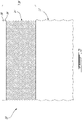
Fig. 2 is a schematic cross-sectional view of part of a cushioning element which may be used in an aircraft such as shown inFig. 1 , in accordance with a particular example not forming part of the invention; -
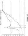
Fig. 3 shows exemplary graphs of a frequency distribution of a sound absorption coefficient for a cushioning element in accordance with a particular embodiment and for an un-tuned foam mattress; and -
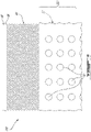
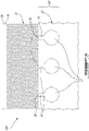
Figs. 4-6 are schematic cross-sectional views of parts of cushioning elements which may be used in an aircraft such as shown inFig. 1 , in accordance with an example not forming part of the invention (Fig. 4 ) and alternate embodiments (Figs 5 ,6 ). - In the drawings, embodiments of the invention are illustrated by way of example. It is to be expressly understood that the description and drawings are only for purposes of illustration and as an aid to understanding. They are not intended to be a definition of the limits of the invention.
- Referring to the drawings and more particularly to
Fig. 1 , an aircraft is shown at 1, and is generally described to illustrate some components for reference purposes in the present disclosure. The aircraft 1 has a fuselage 2 having a fore end at which a cockpit is located, and an aft end supporting a tail assembly, with the cabin generally located between the cockpit and the tail assembly. The tail assembly comprises avertical stabilizer 3 with a rudder, and horizontal stabilizers 4 with elevators. The tail assembly has a fuselage-mounted tail, but other configurations may also be used for the aircraft 1, such as cruciform, T-tail, etc.Wings 5 project laterally from the fuselage. The aircraft 1 has engines 6 supported by thewings 5, although the engines 6 could also be mounted to the fuselage 2. The aircraft 1 is shown as a jet-engine aircraft, but may also be a propeller aircraft. - Rotating or vibrating components of the aircraft 1 can produce tonal noise; cavity resonance may also produce tonal noise. Tonal noise can be defined by a noise concentrated in a narrow part of the spectrum or containing a high proportion of energy at a single frequency or within a limited frequency range - as opposed to non-tonal noise which is typically spread over a wide band of frequencies. Tonal noise is generally more noticeable than non-tonal noise of the same level, and accordingly dampening of the tonal noise within the aircraft cabin is desirable.
- Tonal noise generated by rotating components has a predictable frequency which depends on the rotational speed and structure of the rotating components. For example, the engine 6 may include low pressure and high pressure rotatable shafts producing tonal noise at different frequencies, these frequencies being affected by the number of blades connected to the shaft, vanes interacting with the flow, etc. Other rotatable components may also produce tonal noise, for example gearboxes. Other systems may also produce tonal noise, including, but not limited to, hydraulic systems (e.g. hydraulic pumps), electrical transformers, other types of turbines/fans/compressors, pumps, propellers, cavities (cavity resonance), etc.
- The aircraft cabin may contain several cushioning elements, for example seat cushions (seating surface, back rest), sofa cushions (seating surface, back rest), pillows, and, in cabin configurations including sleeping quarters, mattresses. The term "cushioning element" as used herein is intended to include any soft and/or padded and/or impact absorbing element designed for comfort of the user for sitting, kneeling or lying thereon, as well as any soft and/or padded and/or impact absorbing element designed to absorb impacts, for example overlaying a structure of the cabin (e.g. cabinet) to prevent injury of users upon impact with such structure. Cushioning elements may include padding material (e.g. foam layer(s), foam beads, feathers, unwoven fabric, open or closed cell foam, etc.) and/or springs. Cushioning elements may include an outer envelope made of cloth, other types of fabric, natural or synthetic leather, etc.
- In the present specification, tuned absorbers are embedded in cushioning elements to reduce noise at particular frequencies corresponding to the tonal noise generated by the aircraft engine(s). In some embodiments, the embedded tuned absorber as a whole is not visible from outside of the cushioning element. In other embodiments the outer envelope of the cushioning element may be part of the tuned absorber, however the remaining part of the embedded tuned absorber is not visible from outside of the cushioning element, and the apparent outer surface of the outer envelope is preferably not modified to be part of the tuned absorber (e.g., the outer envelope is not perforated). The cushioning element may accordingly include the tuned absorber without changing its appearance, i.e. without affecting the esthetic aspect of the cushioning element.
- The term "tuned absorber" as used herein is intended to include any apparatus that is tuned to absorb noise at a specific frequency. Non-limiting examples of tuned absorbers are provided in the exemplary embodiments described below.
- Referring to
Fig. 2 , acushioning element 10 in accordance with a particular example not forming part of the invention is shown, which may be for example a mattress. Thecushioning element 10 includes afoam core 12, a plurality ofsprings 14 extending from thefoam core 12, and atop layer 16 of material supported by thesprings 14. The bottom of thecushioning element 10 may be a mirror image of the layup shown, so that thecushioning element 10 is reversible; alternately, thefoam core 12 may define the bottom of thecushioning element 10, or thefoam core 12 may be omitted. Other variations are possible, including, but not limited to, two or more superimposed layers ofsprings 14, a layer ofsprings 14 sandwiched between twofoam cores 12, etc. - An
outer layer 18 overlays thetop layer 16 and defines an outer surface of thecushioning element 10. In a particular embodiment, theouter layer 18 forms or is part of an outer envelope defining the outer surface of theentire cushioning element 10; in a particular embodiment, this outer envelope is unperforated, i.e. it does not include holes other than the voids which may be naturally present in the structure of the fabric forming the outer envelope (e.g. space between woven fibers, voids of open cell material). - In a particular embodiment, the
foam core 12 is made of a suitable open cell foam, for example a polyurethane foam. Other suitable materials may alternately be used, including, but not limited to, closed cell foam or semi open cell foam; fluoropolymer foam, polyamide foam, thermoplastic elastomer foam. - In a particular example not forming part of the invention, the
springs 14 are made of plastic filaments. Other suitable spring materials include, but are not limited to, suitable metals, unwoven fabrics, and open or closed cell foams. Although schematically depicted with a zigzag shape, it is understood that thesprings 14 may have any other suitable configuration (e.g. a curved C-type shape) allowing thesprings 14 to bias the top andouter layers outer layers - In a particular embodiment, the top and
outer layers layers springs 14, it is understood that alternately a single layer may be provided, or more than two layers. - In this example not forming part of the invention, the tuned absorber 20 embedded in the
cushioning element 10 is defined by the spring-mass system formed by thesprings 14 and the layer(s) 16, 18 of material supported by thesprings 14. The spring-mass system is tuned to the predetermined noise frequency (e.g. tonal noise frequency) to be absorbed. Such tuning can be done by changing the properties of thesprings 14, for example by changing the number ofsprings 14, the wire diameter, internal spring diameter, external spring diameter, pitch, stiffness, preload, shape and/or length of thesprings 14, etc. Such tuning can also be done by changing the mass supported by thesprings 14, for example by varying the number and/or the thickness of the layer(s) 16, 18 of material on top of thesprings 14, and/or the density of the material used in the layer(s) 16, 18 on top of thesprings 14. The properties of thesprings 14 and/or mass of the layer(s) 16, 18 supported by thesprings 14 are varied until thecushioning element 10 is tuned to the predetermined noise frequency. Verification of the tuning of the cushioning element may be done for example by measuring and plotting the sound absorption coefficient of the cushioning element over a wide range of frequencies. - Referring to
Fig. 3 , an exemplary plot T of the sound absorption coefficient for a tuned cushioning element (i.e. a cushioning element including a tuned vibration absorber, such as cushioning element 10) and an exemplary plot U of the sound absorption coefficient for an un-tuned foam cushioning element are shown. The sound absorption coefficient α is defined as the ratio of energy absorbed by a material to the energy incident upon its surface, and can be calculated as
- The peak P does not necessarily define the maximum sound absorption coefficient of the cushioning element, but represents a significant local increase in the sound absorption coefficient curve. In a particular embodiment, the peak P corresponds to a sound absorption coefficient value at least 5% above the sound absorption coefficient at adjacent frequencies; in a particular embodiment, the peak P corresponds to a sound absorption coefficient value at least 10% above the sound absorption coefficient at adjacent frequencies.
- The frequency X for which the tuned absorber (and accordingly the cushioning element) is tuned is a frequency value within the audible range, and corresponds to the frequency of a noise (e.g. tonal noise) to be absorbed. In the invention, the frequency X has a value of at least 20 Hz, and in another particular embodiment the frequency X has a value of at least 50 Hz. In a particular embodiment, the frequency X is within the range extending from 50 Hz to 100 Hz, which may correspond for example to the frequency of the tonal noise produced by the low pressure (e.g. fan) shaft of each engine 6. In a particular embodiment, the frequency X is within the range extending from 100 Hz to 350 Hz or from 100 Hz to 500 Hz, which may correspond for example to the frequency of the tonal noise produced by the high pressure (core) shaft of each engine 6. Other values are also possible, for example up to 1000 Hz.
- Referring to
Fig. 4 , acushioning element 110 in accordance with another particular example not forming part of the invention is shown, suitable to be tuned to absorb noise (e.g. tonal noise) as described above. Elements similar to that of thecushioning element 10 ofFig. 2 are identified by the same reference numerals and will not be further described herein. Although thecushioning element 110 is shown as including thesprings 14 andtop layer 16, it is understood that alternately thesprings 14 and/ortop layer 16 may be omitted. For example, thecushioning element 110 may include only thefoam core 12 and theouter layer 18 defining the outer envelope and outer surface of thecushioning element 110. - In this example not forming part of the invention, the
tuned absorber 120 is defined in thefoam core 12. Thefoam core 12 includes one or more portion(s) 32, 34 having a different density and/or stiffness than theremainder 36 of thefoam core 12. In the example not forming part of the invention shown, aportion 32 of thefoam core 12 having a different density/stiffness than theremainder 36 of thefoam core 12 is defined as a foam layer superimposed over theremainder 36 of the foam core and extending along an entire width and length of thecushioning element 110.Portions 34 of the foam core having a different density/stiffness than theremainder 36 of thefoam core 12 are also defined in pieces or blocks, shown here with a rectangular cross-section, embedded in theremainder 36 of thefoam core 12. It is understood that the portion(s) of the foam core having a different density/stiffness than the remainder of the foam core may be defined only as superimposed layer(s) or only as embedded piece(s), and that the shape of the embedded pieces may be varied. - The portion(s) 32, 34 of the
foam core 12 having a different density/stiffness define thetuned absorber 120. Thetuned absorber 120 can be tuned by changing the size and/or number of the portion(s) 32, 34 of thefoam core 12 having a different density/stiffness, or by selecting a particular density/stiffness (e.g., a particular foam material) used in the portion(s) 32, 34 of thefoam core 12 having a different density/stiffness. The size, number and/or density/stiffness of the portion(s) 32, 34 of thefoam core 12 having a different density/stiffness are varied until thecushioning element 110 is tuned to the predetermined noise frequency (e.g. tonal noise frequency). Different regions of thecushioning element 110 can be tuned to absorb noise of different frequencies. Verification of the tuning of thecushioning element 110 with thetuned absorber 120 may be done for example by measuring and plotting the sound absorption coefficient of thecushioning element 110 over a wide range of frequencies to determine the position of the peak(s) P, as set forth above. - Referring to
Fig. 5 , acushioning element 210 in accordance with a particular embodiment is shown, suitable to be tuned to absorb noise (e.g. tonal noise) as described above. Elements similar to that of the previously describedcushioning elements cushioning element 210 is shown as including thesprings 14 andtop layer 16, it is understood that alternately thesprings 14 and/ortop layer 16 may be omitted. In the invention, thecushioning element 210 includes only thefoam core 12. In an embodiment, it also includes theouter layer 18 defining the outer envelope and outer surface of thecushioning element 210. - In the invention, the
tuned absorber 220 is also defined in thefoam core 12. Thefoam core 12 include voids 42 (i.e. portions free of foam, filled for example with ambient air) formed in thefoam core 12. Although thevoids 42 are shown as being defined in a regular pattern of spherical voids, it is understood that the shape and distribution of thevoids 42 may vary. - The
voids 42 in thefoam core 12 define thetuned absorber 220. Thetuned absorber 220 is tuned by changing the size, number, pattern and/or distribution ofvoids 42 provided in thefoam core 12. The size, number, pattern and/or distribution ofvoids 42 in thefoam core 12 are varied until thecushioning element 210 is tuned to the predetermined noise frequency (e.g. tonal noise frequency). Different regions of thecushioning element 110 can be tuned to absorb noise of different frequencies. Verification of the tuning of thecushioning element 210 with thetuned absorber 220 may be done for example by measuring and plotting the sound absorption coefficient of thecushioning element 210 over a wide range of frequencies to determine the position of the peak(s) P, as set forth above. - Referring to
Fig. 6 , acushioning element 310 in accordance with another particular embodiment is shown, suitable to be tuned to absorb noise (e.g. tonal noise) as described above. Elements similar to that of the previously describedcushioning elements cushioning element 310 is shown as including thesprings 14 andtop layer 16, it is understood that alternately thesprings 14 and/ortop layer 16 may be omitted. In the invention, thecushioning element 310 includes only thefoam core 12. In an embodiment, it also includes theouter layer 18 defining the outer envelope and outer surface of thecushioning element 310. - In the invention, the
tuned absorber 320 is also defined in thefoam core 12. In an embodiment, the foam core include voids 52 (i.e. portions free of foam, filled for example with ambient air) formed in thefoam core 12, in fluid communication withports 54 having a smaller cross-sectional area than the voids 52. Although the voids 52 are shown as being defined as spaced apart spherical voids, it is understood that the shape, pattern and distribution of the voids 52 may vary. Theports 54 may each define a neck extending from the respective void 52 to anopening 56 defined in the surface of thefoam core 12, as shown. - The voids 52 with
ports 54 may define Helmholtz resonators, where the volume of air in and near theport 54 vibrates and produces air resonance at a particular frequency - the air trapped in and near theport 54 acts as a mass and the air in the void 52 itself acts as a spring. The voids 52 withports 54, or resonators, thus define thetuned absorber 320. Thetuned absorber 320 is tuned by changing the size, number, pattern and/or distribution of voids 52 provided in thefoam core 12 and, in an embodiment, additionally of the relative size of theirports 54. The size, number, pattern and/or distribution of voids 52 in thefoam core 12 and, in an embodiment, additionally the size of theirports 54 are varied until thecushioning element 310 is tuned to the predetermined noise frequency (e.g. tonal noise frequency). Different regions of thecushioning element 110 can be tuned to absorb noise of different frequencies, for example by having different resonators tuned to different frequencies. Verification of the tuning of thecushioning element 310 with thetuned absorber 320 may be done for example by measuring and plotting the sound absorption coefficient of the cushioning element over a wide range of frequencies to determine the position of the peak(s) P, as set forth above. - In the invention, an assembly of
cushioning elements absorbers - In a particular embodiment and in use, noise absorption can thus be provided within the cabin of the aircraft by determining a predetermined frequency of at least 20 Hz or at least 50 Hz of an undesirable noise within the cabin, and configuring an internal structure of the
cushioning element tuned absorber cushioning element voids 42, 52 within thefoam core 12. When voids 42, 52 are defined, configuring the internal structure of thecushioning element ports 54 having a smaller cross-sectional area than that of the voids 52 and in fluid communication with the voids 52 so that the voids 52 andports 54 define resonators. - In a particular embodiment, the internal structure of the
cushioning element cushioning element - As set forth above, the internal structure of the
cushioning element cushioning element cushioning element - Providing the noise absorption further includes determining a second frequency of another undesirable noise within the cabin, higher than the first frequency, and similarly configuring the internal structure of an additional
cabin cushioning element - In a particular embodiment, the use of existing cushioning elements to provide tuned absorbers allow for tonal noise absorption to be provided without the need to add additional and potentially bulky structure in the aircraft, allowing for tuned absorbers to be provided with no or with minimal impact on the aircraft weight.
- It is understood that any two or more of the tuned
absorbers absorbers - While the methods and systems described herein have been described and shown with reference to particular steps performed in a particular order, it will be understood that these steps may be combined, sub-divided or reordered to form an equivalent method without departing from the teachings of the present invention as set forth in the appended claims. Accordingly, the order and grouping of the steps is not a limitation of the present invention.
- The above description is meant to be exemplary only, and one skilled in the art will recognize that changes may be made to the embodiments described without departing from the scope of the invention as set forth in the appended claims. Modifications which fall within the scope of the present invention will be apparent to those skilled in the art, in light of a review of this disclosure, and such modifications are intended to fall within the appended claims.
Claims (9)
- A cushioning assembly for use in a cabin of an aircraft with at least one engine comprising:a first cushioning element (210, 310) having an internal structure including at least a first tuned absorber (220, 320) embedded within the first cushioning element (210, 310), the first tuned absorber (220, 320) being tuned to absorb noise at a first predetermined frequency of at least 20 Hz; anda second cushioning element (210, 310) having an internal structure including at least one second tuned absorber (220, 320) embedded within the second cushioning element (210, 310), the second tuned absorber (220, 320) tuned to absorb noise at a second predetermined frequency greater than the first predetermined frequency, said first and second predetermined frequencies being in the audible range, the assembly being characterized in that the first predetermined frequency corresponds to a frequency of a tonal noise produced by a low pressure shaft of the at least one engine and the second predetermined frequency corresponds to a frequency of a tonal noise produced by a high pressure shaft of the at least one engine; an internal structure of the cushioning elements includes a foam core (12), the tuned absorbers (220, 320) being defined in the foam core and including voids (42, 52) within the foam core, the tuned absorbers being tuned by changing the size, number, pattern and/or distribution of the voids and the first cushioning element (210, 310) is a mattress and the second cushioning element (210, 310) is a seat cushion having a smaller volume than the mattress.
- The assembly as defined in claim 1, wherein the first predetermined frequency is at least 50 Hz.
- The assembly as defined in claim 1 or 2, wherein a frequency distribution of sound absorption coefficient of the first cushioning element (210, 310) defines a peak at the first predetermined frequency, the peak corresponding to a value of sound absorption coefficient at least 5% above a sound absorption coefficient of the first cushioning element (210, 310) at frequencies adjacent the first predetermined frequency.
- The assembly as defined in claim 3, wherein the value of sound absorption coefficient at the peak is at least 10% above the sound absorption coefficient of the first cushioning element (210, 310) at frequencies adjacent the first predetermined frequency.
- The assembly as defined in any one of claims 1 to 4, wherein the first cushioning element (210, 310) includes an outer envelope defining an outer surface of the first cushioning element (210, 310), the outer envelope being unperforated.
- The assembly as defined in any one of claims 1 to 5, wherein the first predetermined frequency is at most 100 Hz.
- The assembly as defined in any one of claims 1 to 5, wherein the second predetermined frequency is within a range defined from 100 Hz to 500 Hz.
- The assembly as defined in claim 1, wherein the voids (52) are in fluid communication with ports (54) having a smaller cross-sectional area than that of the voids, the voids (52) and the ports (54) defining resonators.
- A method of providing noise absorption with an assembly within a cabin of an aircraft having at least one engine, the method comprising:determining a first predetermined frequency of at least 20 Hz of an undesirable noise within the cabin, the first predetermined frequency corresponding to a frequency of a tonal noise produced by a low pressure shaft of the at least one engine;determining a second predetermined frequency greater than the first predetermined frequency of an undesirable noise within the cabin, the second predetermined frequency corresponding to a frequency of a tonal noise produced by a high pressure shaft of the at least one engine;configuring a foam core (12) of an internal structure of a first cushioning element (210, 310) of the assembly to define a first tuned absorber (220, 320) tuned to absorb noise at the first predetermined frequency; andconfiguring a foam core of an internal structure of a second cushioning element (210, 310) of the assembly to define a second tuned absorber (220, 320) tuned to absorb noise at the second predetermined frequency, said first and second predetermined frequencies being in the audible range, the cushioning elements (210, 310) in use being located in the cabin, wherein an internal structure of the cushioning elements (210, 310) includes the foam core (12), the tuned absorbers (220, 320) being defined in the foam core (12) and including voids (42, 52) within the foam core (12), the tuned absorbers being tuned by changing the size, number, pattern and/or distribution of the voids and wherein the first cushioning element (210, 310) is a mattress and the second cushioning element (210, 310) is a seat cushion having a smaller volume than the mattress.
Applications Claiming Priority (2)
| Application Number | Priority Date | Filing Date | Title |
|---|---|---|---|
| US201662430036P | 2016-12-05 | 2016-12-05 | |
| PCT/IB2017/057665 WO2018104868A1 (en) | 2016-12-05 | 2017-12-05 | Cushioning element with tuned absorber |
Publications (2)
| Publication Number | Publication Date |
|---|---|
| EP3549128A1 EP3549128A1 (en) | 2019-10-09 |
| EP3549128B1 true EP3549128B1 (en) | 2022-04-13 |
Family
ID=60702913
Family Applications (1)
| Application Number | Title | Priority Date | Filing Date |
|---|---|---|---|
| EP17817186.4A Active EP3549128B1 (en) | 2016-12-05 | 2017-12-05 | Cushioning element with tuned absorber |
Country Status (3)
| Country | Link |
|---|---|
| US (1) | US11514880B2 (en) |
| EP (1) | EP3549128B1 (en) |
| WO (1) | WO2018104868A1 (en) |
Families Citing this family (1)
| Publication number | Priority date | Publication date | Assignee | Title |
|---|---|---|---|---|
| WO2026018156A1 (en) * | 2024-07-18 | 2026-01-22 | T4G Engineering Gmbh | Absorbing device for reducing noise vibrations |
Family Cites Families (15)
| Publication number | Priority date | Publication date | Assignee | Title |
|---|---|---|---|---|
| JPH0688514B2 (en) | 1986-01-24 | 1994-11-09 | 日産自動車株式会社 | Resonance reduction cushion |
| AT399488B (en) * | 1991-04-22 | 1995-05-26 | Greiner & Soehne C A | Seat cushion, in particular an aircraft seat |
| GB9705402D0 (en) | 1996-12-04 | 1997-04-30 | Pritex Ltd | Apparatus for and method of attenuating acoustic energy |
| US6648100B2 (en) | 2001-10-24 | 2003-11-18 | Lear Corporation | Method of tuning acoustical absorption in a vehicle interior |
| US7677660B2 (en) | 2007-09-06 | 2010-03-16 | Lear Corporation | Acoustically tuned seating assembly |
| JP5326472B2 (en) * | 2007-10-11 | 2013-10-30 | ヤマハ株式会社 | Sound absorption structure |
| DE102009007891A1 (en) | 2009-02-07 | 2010-08-12 | Willsingh Wilson | Resonance sound absorber in multilayer design |
| BR112013000807A2 (en) * | 2010-07-15 | 2016-05-24 | Aishin Kako Kk | structure having a sound absorbing feature |
| US8974003B2 (en) * | 2012-03-30 | 2015-03-10 | Toyota Motor Engineering & Manufacturing North America, Inc. | Rear seat cushion sound reduction mat |
| US8657067B1 (en) * | 2012-09-25 | 2014-02-25 | The Boeing Company | Acoustic damping device for noise reduction |
| GB201410856D0 (en) * | 2014-06-18 | 2014-07-30 | Carbon Air Ltd | Vibration propagation |
| US9630575B2 (en) * | 2015-09-30 | 2017-04-25 | GM Global Technology Operations LLC | Panel assembly with noise attenuation system |
| CA3053172C (en) * | 2017-04-03 | 2021-03-30 | Cascade Engineering, Inc. | Acoustic fiber silencer |
| US10077011B1 (en) * | 2017-05-09 | 2018-09-18 | Ford Global Technologies, Llc | Vehicle underbody acoustic panels |
| EP3409468B1 (en) * | 2017-06-01 | 2020-08-19 | Autoneum Management AG | Aestetic floor covering system |
-
2017
- 2017-12-05 US US16/466,440 patent/US11514880B2/en active Active
- 2017-12-05 WO PCT/IB2017/057665 patent/WO2018104868A1/en not_active Ceased
- 2017-12-05 EP EP17817186.4A patent/EP3549128B1/en active Active
Non-Patent Citations (1)
| Title |
|---|
| None * |
Also Published As
| Publication number | Publication date |
|---|---|
| US20200074972A1 (en) | 2020-03-05 |
| WO2018104868A1 (en) | 2018-06-14 |
| EP3549128A1 (en) | 2019-10-09 |
| US11514880B2 (en) | 2022-11-29 |
Similar Documents
| Publication | Publication Date | Title |
|---|---|---|
| EP3225459B1 (en) | Seat back for vehicle | |
| US8147001B2 (en) | Method of absorbing energy in an aircraft passenger seat assembly | |
| US7871039B2 (en) | Modular passenger seat for an aircraft | |
| EP2024230B1 (en) | Lightweight aircraft passenger seat with composite construction | |
| CN104044317B (en) | Padded coaming | |
| EP3159256B1 (en) | Improved thermal-acoustic sections for an aircraft | |
| US20170174346A1 (en) | Seat Cushion for Use by Airline Passengers | |
| US20120256466A1 (en) | Seat cushion, for instance for an aircraft seat, and a method for manufacturing such a seat cushion | |
| US20060162081A1 (en) | Adaptive pneumatic sitting and reclining cushion for vehicles and aircraft | |
| CN107847056A (en) | Auto use chair padded coaming and auto use chair | |
| EP3549128B1 (en) | Cushioning element with tuned absorber | |
| GB2588857A (en) | Multifrequency absorption acoustic panel for an aircraft nacelle | |
| WO2019017834A1 (en) | Seat-back for a passenger seat | |
| US7410126B2 (en) | Tunable acoustic absorption system for an aircraft cabin | |
| DE102008032022A1 (en) | Acoustically coordinated seating arrangement | |
| CN111065545B (en) | Cushion for vehicle seat with 3D-shaped non-woven part for reinforcing side wings covered with foam | |
| EP4021806B1 (en) | Auxetic support elements with ergonomic curvatures for passenger seats | |
| EP3225460A1 (en) | Cushion assembly | |
| CA3063343A1 (en) | Seat cushion for airline passengers | |
| DE102004008407A1 (en) | Seat for land vehicle or airplane, includes shell holding open-cell foam cushion with impermeable covering, and gas connection varying cushion expansion | |
| Chen et al. | Investigation of helicopter seat structural dynamics for aircrew vibration mitigation | |
| ITRM970340A1 (en) | PERFECTED CUSHION STRUCTURE | |
| CN204196753U (en) | Carpet and vehicle | |
| US20250333175A1 (en) | Integrated cushion lattice structures for vibration damping for aircraft seating | |
| US20180057138A1 (en) | Aircraft with cabin acoustic systems having quarter wavelength absorbers |
Legal Events
| Date | Code | Title | Description |
|---|---|---|---|
| STAA | Information on the status of an ep patent application or granted ep patent |
Free format text: STATUS: UNKNOWN |
|
| STAA | Information on the status of an ep patent application or granted ep patent |
Free format text: STATUS: THE INTERNATIONAL PUBLICATION HAS BEEN MADE |
|
| PUAI | Public reference made under article 153(3) epc to a published international application that has entered the european phase |
Free format text: ORIGINAL CODE: 0009012 |
|
| STAA | Information on the status of an ep patent application or granted ep patent |
Free format text: STATUS: REQUEST FOR EXAMINATION WAS MADE |
|
| 17P | Request for examination filed |
Effective date: 20190627 |
|
| AK | Designated contracting states |
Kind code of ref document: A1 Designated state(s): AL AT BE BG CH CY CZ DE DK EE ES FI FR GB GR HR HU IE IS IT LI LT LU LV MC MK MT NL NO PL PT RO RS SE SI SK SM TR |
|
| AX | Request for extension of the european patent |
Extension state: BA ME |
|
| DAV | Request for validation of the european patent (deleted) | ||
| DAX | Request for extension of the european patent (deleted) | ||
| STAA | Information on the status of an ep patent application or granted ep patent |
Free format text: STATUS: EXAMINATION IS IN PROGRESS |
|
| 17Q | First examination report despatched |
Effective date: 20200416 |
|
| REG | Reference to a national code |
Ref country code: DE Ref legal event code: R079 Ref document number: 602017056007 Country of ref document: DE Free format text: PREVIOUS MAIN CLASS: G10K0011172000 Ipc: G10K0011168000 |
|
| GRAP | Despatch of communication of intention to grant a patent |
Free format text: ORIGINAL CODE: EPIDOSNIGR1 |
|
| STAA | Information on the status of an ep patent application or granted ep patent |
Free format text: STATUS: GRANT OF PATENT IS INTENDED |
|
| RIC1 | Information provided on ipc code assigned before grant |
Ipc: B60N 2/70 20060101ALI20210924BHEP Ipc: B64D 11/06 20060101ALI20210924BHEP Ipc: G10K 11/172 20060101ALI20210924BHEP Ipc: G10K 11/168 20060101AFI20210924BHEP |
|
| INTG | Intention to grant announced |
Effective date: 20211025 |
|
| GRAS | Grant fee paid |
Free format text: ORIGINAL CODE: EPIDOSNIGR3 |
|
| GRAA | (expected) grant |
Free format text: ORIGINAL CODE: 0009210 |
|
| STAA | Information on the status of an ep patent application or granted ep patent |
Free format text: STATUS: THE PATENT HAS BEEN GRANTED |
|
| AK | Designated contracting states |
Kind code of ref document: B1 Designated state(s): AL AT BE BG CH CY CZ DE DK EE ES FI FR GB GR HR HU IE IS IT LI LT LU LV MC MK MT NL NO PL PT RO RS SE SI SK SM TR |
|
| REG | Reference to a national code |
Ref country code: GB Ref legal event code: FG4D |
|
| REG | Reference to a national code |
Ref country code: CH Ref legal event code: EP |
|
| REG | Reference to a national code |
Ref country code: DE Ref legal event code: R096 Ref document number: 602017056007 Country of ref document: DE |
|
| REG | Reference to a national code |
Ref country code: IE Ref legal event code: FG4D |
|
| REG | Reference to a national code |
Ref country code: AT Ref legal event code: REF Ref document number: 1484028 Country of ref document: AT Kind code of ref document: T Effective date: 20220515 |
|
| REG | Reference to a national code |
Ref country code: LT Ref legal event code: MG9D |
|
| REG | Reference to a national code |
Ref country code: NL Ref legal event code: MP Effective date: 20220413 |
|
| REG | Reference to a national code |
Ref country code: AT Ref legal event code: MK05 Ref document number: 1484028 Country of ref document: AT Kind code of ref document: T Effective date: 20220413 |
|
| PG25 | Lapsed in a contracting state [announced via postgrant information from national office to epo] |
Ref country code: NL Free format text: LAPSE BECAUSE OF FAILURE TO SUBMIT A TRANSLATION OF THE DESCRIPTION OR TO PAY THE FEE WITHIN THE PRESCRIBED TIME-LIMIT Effective date: 20220413 |
|
| PG25 | Lapsed in a contracting state [announced via postgrant information from national office to epo] |
Ref country code: SE Free format text: LAPSE BECAUSE OF FAILURE TO SUBMIT A TRANSLATION OF THE DESCRIPTION OR TO PAY THE FEE WITHIN THE PRESCRIBED TIME-LIMIT Effective date: 20220413 Ref country code: PT Free format text: LAPSE BECAUSE OF FAILURE TO SUBMIT A TRANSLATION OF THE DESCRIPTION OR TO PAY THE FEE WITHIN THE PRESCRIBED TIME-LIMIT Effective date: 20220816 Ref country code: NO Free format text: LAPSE BECAUSE OF FAILURE TO SUBMIT A TRANSLATION OF THE DESCRIPTION OR TO PAY THE FEE WITHIN THE PRESCRIBED TIME-LIMIT Effective date: 20220713 Ref country code: LT Free format text: LAPSE BECAUSE OF FAILURE TO SUBMIT A TRANSLATION OF THE DESCRIPTION OR TO PAY THE FEE WITHIN THE PRESCRIBED TIME-LIMIT Effective date: 20220413 Ref country code: HR Free format text: LAPSE BECAUSE OF FAILURE TO SUBMIT A TRANSLATION OF THE DESCRIPTION OR TO PAY THE FEE WITHIN THE PRESCRIBED TIME-LIMIT Effective date: 20220413 Ref country code: GR Free format text: LAPSE BECAUSE OF FAILURE TO SUBMIT A TRANSLATION OF THE DESCRIPTION OR TO PAY THE FEE WITHIN THE PRESCRIBED TIME-LIMIT Effective date: 20220714 Ref country code: FI Free format text: LAPSE BECAUSE OF FAILURE TO SUBMIT A TRANSLATION OF THE DESCRIPTION OR TO PAY THE FEE WITHIN THE PRESCRIBED TIME-LIMIT Effective date: 20220413 Ref country code: ES Free format text: LAPSE BECAUSE OF FAILURE TO SUBMIT A TRANSLATION OF THE DESCRIPTION OR TO PAY THE FEE WITHIN THE PRESCRIBED TIME-LIMIT Effective date: 20220413 Ref country code: BG Free format text: LAPSE BECAUSE OF FAILURE TO SUBMIT A TRANSLATION OF THE DESCRIPTION OR TO PAY THE FEE WITHIN THE PRESCRIBED TIME-LIMIT Effective date: 20220713 Ref country code: AT Free format text: LAPSE BECAUSE OF FAILURE TO SUBMIT A TRANSLATION OF THE DESCRIPTION OR TO PAY THE FEE WITHIN THE PRESCRIBED TIME-LIMIT Effective date: 20220413 |
|
| PG25 | Lapsed in a contracting state [announced via postgrant information from national office to epo] |
Ref country code: RS Free format text: LAPSE BECAUSE OF FAILURE TO SUBMIT A TRANSLATION OF THE DESCRIPTION OR TO PAY THE FEE WITHIN THE PRESCRIBED TIME-LIMIT Effective date: 20220413 Ref country code: PL Free format text: LAPSE BECAUSE OF FAILURE TO SUBMIT A TRANSLATION OF THE DESCRIPTION OR TO PAY THE FEE WITHIN THE PRESCRIBED TIME-LIMIT Effective date: 20220413 Ref country code: LV Free format text: LAPSE BECAUSE OF FAILURE TO SUBMIT A TRANSLATION OF THE DESCRIPTION OR TO PAY THE FEE WITHIN THE PRESCRIBED TIME-LIMIT Effective date: 20220413 Ref country code: IS Free format text: LAPSE BECAUSE OF FAILURE TO SUBMIT A TRANSLATION OF THE DESCRIPTION OR TO PAY THE FEE WITHIN THE PRESCRIBED TIME-LIMIT Effective date: 20220813 |
|
| REG | Reference to a national code |
Ref country code: DE Ref legal event code: R097 Ref document number: 602017056007 Country of ref document: DE |
|
| PG25 | Lapsed in a contracting state [announced via postgrant information from national office to epo] |
Ref country code: SM Free format text: LAPSE BECAUSE OF FAILURE TO SUBMIT A TRANSLATION OF THE DESCRIPTION OR TO PAY THE FEE WITHIN THE PRESCRIBED TIME-LIMIT Effective date: 20220413 Ref country code: SK Free format text: LAPSE BECAUSE OF FAILURE TO SUBMIT A TRANSLATION OF THE DESCRIPTION OR TO PAY THE FEE WITHIN THE PRESCRIBED TIME-LIMIT Effective date: 20220413 Ref country code: RO Free format text: LAPSE BECAUSE OF FAILURE TO SUBMIT A TRANSLATION OF THE DESCRIPTION OR TO PAY THE FEE WITHIN THE PRESCRIBED TIME-LIMIT Effective date: 20220413 Ref country code: EE Free format text: LAPSE BECAUSE OF FAILURE TO SUBMIT A TRANSLATION OF THE DESCRIPTION OR TO PAY THE FEE WITHIN THE PRESCRIBED TIME-LIMIT Effective date: 20220413 Ref country code: DK Free format text: LAPSE BECAUSE OF FAILURE TO SUBMIT A TRANSLATION OF THE DESCRIPTION OR TO PAY THE FEE WITHIN THE PRESCRIBED TIME-LIMIT Effective date: 20220413 Ref country code: CZ Free format text: LAPSE BECAUSE OF FAILURE TO SUBMIT A TRANSLATION OF THE DESCRIPTION OR TO PAY THE FEE WITHIN THE PRESCRIBED TIME-LIMIT Effective date: 20220413 |
|
| PLBE | No opposition filed within time limit |
Free format text: ORIGINAL CODE: 0009261 |
|
| STAA | Information on the status of an ep patent application or granted ep patent |
Free format text: STATUS: NO OPPOSITION FILED WITHIN TIME LIMIT |
|
| 26N | No opposition filed |
Effective date: 20230116 |
|
| PG25 | Lapsed in a contracting state [announced via postgrant information from national office to epo] |
Ref country code: AL Free format text: LAPSE BECAUSE OF FAILURE TO SUBMIT A TRANSLATION OF THE DESCRIPTION OR TO PAY THE FEE WITHIN THE PRESCRIBED TIME-LIMIT Effective date: 20220413 |
|
| PG25 | Lapsed in a contracting state [announced via postgrant information from national office to epo] |
Ref country code: SI Free format text: LAPSE BECAUSE OF FAILURE TO SUBMIT A TRANSLATION OF THE DESCRIPTION OR TO PAY THE FEE WITHIN THE PRESCRIBED TIME-LIMIT Effective date: 20220413 |
|
| P01 | Opt-out of the competence of the unified patent court (upc) registered |
Effective date: 20230529 |
|
| REG | Reference to a national code |
Ref country code: CH Ref legal event code: PL |
|
| REG | Reference to a national code |
Ref country code: BE Ref legal event code: MM Effective date: 20221231 |
|
| PG25 | Lapsed in a contracting state [announced via postgrant information from national office to epo] |
Ref country code: LU Free format text: LAPSE BECAUSE OF NON-PAYMENT OF DUE FEES Effective date: 20221205 |
|
| PG25 | Lapsed in a contracting state [announced via postgrant information from national office to epo] |
Ref country code: LI Free format text: LAPSE BECAUSE OF NON-PAYMENT OF DUE FEES Effective date: 20221231 Ref country code: IE Free format text: LAPSE BECAUSE OF NON-PAYMENT OF DUE FEES Effective date: 20221205 Ref country code: CH Free format text: LAPSE BECAUSE OF NON-PAYMENT OF DUE FEES Effective date: 20221231 |
|
| PG25 | Lapsed in a contracting state [announced via postgrant information from national office to epo] |
Ref country code: BE Free format text: LAPSE BECAUSE OF NON-PAYMENT OF DUE FEES Effective date: 20221231 |
|
| PG25 | Lapsed in a contracting state [announced via postgrant information from national office to epo] |
Ref country code: IT Free format text: LAPSE BECAUSE OF FAILURE TO SUBMIT A TRANSLATION OF THE DESCRIPTION OR TO PAY THE FEE WITHIN THE PRESCRIBED TIME-LIMIT Effective date: 20220413 |
|
| PG25 | Lapsed in a contracting state [announced via postgrant information from national office to epo] |
Ref country code: HU Free format text: LAPSE BECAUSE OF FAILURE TO SUBMIT A TRANSLATION OF THE DESCRIPTION OR TO PAY THE FEE WITHIN THE PRESCRIBED TIME-LIMIT; INVALID AB INITIO Effective date: 20171205 |
|
| PG25 | Lapsed in a contracting state [announced via postgrant information from national office to epo] |
Ref country code: CY Free format text: LAPSE BECAUSE OF FAILURE TO SUBMIT A TRANSLATION OF THE DESCRIPTION OR TO PAY THE FEE WITHIN THE PRESCRIBED TIME-LIMIT Effective date: 20220413 |
|
| PG25 | Lapsed in a contracting state [announced via postgrant information from national office to epo] |
Ref country code: MK Free format text: LAPSE BECAUSE OF FAILURE TO SUBMIT A TRANSLATION OF THE DESCRIPTION OR TO PAY THE FEE WITHIN THE PRESCRIBED TIME-LIMIT Effective date: 20220413 |
|
| PG25 | Lapsed in a contracting state [announced via postgrant information from national office to epo] |
Ref country code: MC Free format text: LAPSE BECAUSE OF FAILURE TO SUBMIT A TRANSLATION OF THE DESCRIPTION OR TO PAY THE FEE WITHIN THE PRESCRIBED TIME-LIMIT Effective date: 20220413 |
|
| PG25 | Lapsed in a contracting state [announced via postgrant information from national office to epo] |
Ref country code: TR Free format text: LAPSE BECAUSE OF FAILURE TO SUBMIT A TRANSLATION OF THE DESCRIPTION OR TO PAY THE FEE WITHIN THE PRESCRIBED TIME-LIMIT Effective date: 20220413 Ref country code: MC Free format text: LAPSE BECAUSE OF FAILURE TO SUBMIT A TRANSLATION OF THE DESCRIPTION OR TO PAY THE FEE WITHIN THE PRESCRIBED TIME-LIMIT Effective date: 20220413 |
|
| PG25 | Lapsed in a contracting state [announced via postgrant information from national office to epo] |
Ref country code: MT Free format text: LAPSE BECAUSE OF FAILURE TO SUBMIT A TRANSLATION OF THE DESCRIPTION OR TO PAY THE FEE WITHIN THE PRESCRIBED TIME-LIMIT Effective date: 20220413 |
|
| PG25 | Lapsed in a contracting state [announced via postgrant information from national office to epo] |
Ref country code: BG Free format text: LAPSE BECAUSE OF FAILURE TO SUBMIT A TRANSLATION OF THE DESCRIPTION OR TO PAY THE FEE WITHIN THE PRESCRIBED TIME-LIMIT Effective date: 20220413 |
|
| PG25 | Lapsed in a contracting state [announced via postgrant information from national office to epo] |
Ref country code: BG Free format text: LAPSE BECAUSE OF FAILURE TO SUBMIT A TRANSLATION OF THE DESCRIPTION OR TO PAY THE FEE WITHIN THE PRESCRIBED TIME-LIMIT Effective date: 20220413 |
|
| PGFP | Annual fee paid to national office [announced via postgrant information from national office to epo] |
Ref country code: DE Payment date: 20251211 Year of fee payment: 9 |
|
| PGFP | Annual fee paid to national office [announced via postgrant information from national office to epo] |
Ref country code: GB Payment date: 20251219 Year of fee payment: 9 |
|
| PGFP | Annual fee paid to national office [announced via postgrant information from national office to epo] |
Ref country code: FR Payment date: 20251229 Year of fee payment: 9 |