EP3548742B1 - Carbon blade for wind power generator with multi-down conductor - Google Patents
Carbon blade for wind power generator with multi-down conductor Download PDFInfo
- Publication number
- EP3548742B1 EP3548742B1 EP17876442.9A EP17876442A EP3548742B1 EP 3548742 B1 EP3548742 B1 EP 3548742B1 EP 17876442 A EP17876442 A EP 17876442A EP 3548742 B1 EP3548742 B1 EP 3548742B1
- Authority
- EP
- European Patent Office
- Prior art keywords
- down conductor
- blade
- carbon
- conductor
- disposed
- Prior art date
- Legal status (The legal status is an assumption and is not a legal conclusion. Google has not performed a legal analysis and makes no representation as to the accuracy of the status listed.)
- Active
Links
Images


Classifications
-
- F—MECHANICAL ENGINEERING; LIGHTING; HEATING; WEAPONS; BLASTING
- F03—MACHINES OR ENGINES FOR LIQUIDS; WIND, SPRING, OR WEIGHT MOTORS; PRODUCING MECHANICAL POWER OR A REACTIVE PROPULSIVE THRUST, NOT OTHERWISE PROVIDED FOR
- F03D—WIND MOTORS
- F03D80/00—Details, components or accessories not provided for in groups F03D1/00 - F03D17/00
- F03D80/30—Lightning protection
- F03D80/301—Lightning receptor and down conductor systems in or on blades
-
- F—MECHANICAL ENGINEERING; LIGHTING; HEATING; WEAPONS; BLASTING
- F01—MACHINES OR ENGINES IN GENERAL; ENGINE PLANTS IN GENERAL; STEAM ENGINES
- F01D—NON-POSITIVE DISPLACEMENT MACHINES OR ENGINES, e.g. STEAM TURBINES
- F01D5/00—Blades; Blade-carrying members; Heating, heat-insulating, cooling or antivibration means on the blades or the members
- F01D5/12—Blades
-
- F—MECHANICAL ENGINEERING; LIGHTING; HEATING; WEAPONS; BLASTING
- F03—MACHINES OR ENGINES FOR LIQUIDS; WIND, SPRING, OR WEIGHT MOTORS; PRODUCING MECHANICAL POWER OR A REACTIVE PROPULSIVE THRUST, NOT OTHERWISE PROVIDED FOR
- F03D—WIND MOTORS
- F03D1/00—Wind motors with rotation axis substantially parallel to the air flow entering the rotor
- F03D1/06—Rotors
- F03D1/065—Rotors characterised by their construction elements
- F03D1/0675—Rotors characterised by their construction elements of the blades
-
- F—MECHANICAL ENGINEERING; LIGHTING; HEATING; WEAPONS; BLASTING
- F05—INDEXING SCHEMES RELATING TO ENGINES OR PUMPS IN VARIOUS SUBCLASSES OF CLASSES F01-F04
- F05B—INDEXING SCHEME RELATING TO WIND, SPRING, WEIGHT, INERTIA OR LIKE MOTORS, TO MACHINES OR ENGINES FOR LIQUIDS COVERED BY SUBCLASSES F03B, F03D AND F03G
- F05B2240/00—Components
- F05B2240/20—Rotors
- F05B2240/21—Rotors for wind turbines
-
- F—MECHANICAL ENGINEERING; LIGHTING; HEATING; WEAPONS; BLASTING
- F05—INDEXING SCHEMES RELATING TO ENGINES OR PUMPS IN VARIOUS SUBCLASSES OF CLASSES F01-F04
- F05B—INDEXING SCHEME RELATING TO WIND, SPRING, WEIGHT, INERTIA OR LIKE MOTORS, TO MACHINES OR ENGINES FOR LIQUIDS COVERED BY SUBCLASSES F03B, F03D AND F03G
- F05B2240/00—Components
- F05B2240/20—Rotors
- F05B2240/30—Characteristics of rotor blades, i.e. of any element transforming dynamic fluid energy to or from rotational energy and being attached to a rotor
-
- F—MECHANICAL ENGINEERING; LIGHTING; HEATING; WEAPONS; BLASTING
- F05—INDEXING SCHEMES RELATING TO ENGINES OR PUMPS IN VARIOUS SUBCLASSES OF CLASSES F01-F04
- F05B—INDEXING SCHEME RELATING TO WIND, SPRING, WEIGHT, INERTIA OR LIKE MOTORS, TO MACHINES OR ENGINES FOR LIQUIDS COVERED BY SUBCLASSES F03B, F03D AND F03G
- F05B2280/00—Materials; Properties thereof
- F05B2280/20—Inorganic materials, e.g. non-metallic materials
- F05B2280/2006—Carbon, e.g. graphite
-
- Y—GENERAL TAGGING OF NEW TECHNOLOGICAL DEVELOPMENTS; GENERAL TAGGING OF CROSS-SECTIONAL TECHNOLOGIES SPANNING OVER SEVERAL SECTIONS OF THE IPC; TECHNICAL SUBJECTS COVERED BY FORMER USPC CROSS-REFERENCE ART COLLECTIONS [XRACs] AND DIGESTS
- Y02—TECHNOLOGIES OR APPLICATIONS FOR MITIGATION OR ADAPTATION AGAINST CLIMATE CHANGE
- Y02E—REDUCTION OF GREENHOUSE GAS [GHG] EMISSIONS, RELATED TO ENERGY GENERATION, TRANSMISSION OR DISTRIBUTION
- Y02E10/00—Energy generation through renewable energy sources
- Y02E10/70—Wind energy
- Y02E10/72—Wind turbines with rotation axis in wind direction
Definitions
- the disclosure relates to a carbon blade for a wind turbine with multiple down conductors, and more particularly, to a carbon blade for a wind turbine with multiple down conductors that is configured to have the multiple down conductors disposed thereon to prevent a potential difference between a plurality of points to be formed thereon from being generated.
- a wind turbine drives a generator disposed at the inside thereof with wind energy and thus to produce electric power form the wind energy.
- the wind turbine includes the generator and a plurality of blades disposed on the upper portion of a vertically erected tower structure.
- the wind turbine with the blades is typically located on the field or sea surface where the wind blows well, which undesirably causes frequent lightning damage.
- Down conductors may be disposed on the blades of the wind turbine in such a manner as to come into contact with the ground.
- the down conductors are spaced apart from each other by a given distance, so that when they receive lightning, a high internal voltage difference is generated to undesirably cause flashover.
- the disclosure has been made in view of the above-mentioned problems occurring in the prior art, and it is an object of the disclosure to provide a carbon blade for a wind turbine that is configured wherein down conductors are disposed on the outer and inner surfaces thereof, respectively, in such a manner as to be bonded to each other on both ends of the carbon blade, thereby enabling an equipotential bonding structure to be easily formed on the carbon blade.
- the present disclosure relates to a carbon blade for a wind turbine with multiple down conductors, and more particularly, to a carbon blade for a wind turbine with multiple down conductors that limits or prevents a potential difference between a plurality of points thereon from being generated.
- a carbon blade for a wind turbine including: a carbon spar cap located at the center of the width thereof in such a manner as to be extended in a longitudinal direction thereof; a carbon skin disposed extended from a tip to a root thereof to cover the outer surface thereof; a first down conductor located on the surface thereof in such a manner as to partially cover the carbon spar cap in parallel with the carbon spar cap; and a second down conductor located on the inner surface thereof in such a manner as to allow both ends thereof to be connected to the first down conductor by means of a coupling member.
- the first down conductor may be made of an aluminum mesh.
- the second down conductor may be made of a wire woven with a conductor.
- the conductor may be made of copper.
- the coupling member may include a tip coupling member and a root coupling member disposed on both ends of the first down conductor and the second down conductor, and the tip coupling member and the root coupling member being adapted to connect the first down conductor and the second down conductor with each other to allow the potentials of the first down conductor and the second down conductor to be same as each other.
- the first down conductor and the second down conductor may be disposed in parallel with each other.
- the carbon blade may further include a block member disposed on one side of the inner surface of the carbon blade to fix the second down conductor to the inner surface of the carbon blade.
- the block member may be fixed by means of a bolt connecting the coupling member, the first down conductor disposed on the surface of the carbon blade, the carbon blade, and the second down conductor.
- the carbon blade may further include a tip down conductor having one end disposed on the tip portion of the carbon blade in such a manner as to be extended to the tip coupling member.
- the second down conductor may include a front down conductor and a rear down conductor disposed on the front and rear sides of the inner surface of the carbon blade in such a manner as to be extended from the tip coupling member to the root coupling member.
- the tip down conductor may be made of a wire woven with a conductor.
- the conductor of the wire of the tip down conductor may be made of copper.
- the carbon blade for a wind turbine is configured wherein the down conductors are disposed on the outer and inner surfaces thereof in such a manner as to be bonded to each other on both ends of the surface of the carbon blade, thereby enabling an equipotential bonding structure to be easily formed on the surface of the carbon blade.
- the plurality of down conductor is disposed in parallel with each other on the outer and inner surfaces of the carbon blade, thereby offsetting the magnetic fields generated from the plurality of down conductors.
- An exemplary object of the disclosure is to provide a carbon blade for a wind turbine in which down conductors are disposed on the outer and inner surfaces thereof, respectively, in such a manner as to be bonded to each other on both ends of the carbon blade, thereby enabling an equipotential bonding structure to be easily formed on the carbon blade.
- Another exemplary object of the disclosure is to provide a carbon blade for a wind turbine in which even if a down conductor disposed on the outer surface of the carbon blade is damaged, the function of the damaged down conductor is replaced with a down conductor disposed on the inner surface of the carbon blade, thereby reducing or minimizing the damage caused by lightning.
- Yet another exemplary object of the disclosure is to provide a carbon blade for a wind turbine in which a plurality of down conductors are disposed in parallel with each other on the outer and inner surfaces of the carbon blade, thereby offsetting the magnetic fields generated from the plurality of down conductors.
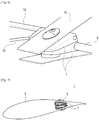
- FIG. 1 is a front view showing a carbon blade for a wind turbine with multiple down conductors according to a first embodiment of the disclosure.
- FIG.1 the detailed configuration of a carbon blade for a wind turbine according to the disclosure and a lightning and flashover reduction device disposed on the carbon blade will be discussed.
- a carbon blade 1 for a wind turbine includes a carbon spar cap 2 located at the center of the width thereof in such a manner as to be extended in a longitudinal direction thereof, a carbon skin 3 extending from a tip to a root thereof to cover the outer surface thereof, a first down conductor 4 located on the surface thereof in such a manner as to partially cover the carbon spar cap 2 in parallel with the carbon spar cap 2, and a second down conductor 5 located on the inner surface thereof in such a manner as to allow both ends thereof to be connected to the first down conductor 4 by a coupling member 6.
- the first down conductor 4 is made of an aluminum mesh
- the second down conductor 5 is made of a wire woven with a conductor.
- the conductor may be made of copper.
- the carbon skin 3 of the carbon blade 1 may be made of carbon fibers that cover over the entire area thereof.
- the carbon spar cap 2 is located at the center of the width thereof in such a manner as to be extended in the longitudinal direction thereof.
- the first down conductor 4 which may be made of aluminum mesh, may cover the entire surface of the carbon spar cap 2 except the tip portion thereof in such a manner as to be linearly extended in the longitudinal direction of the carbon blade.
- the second down conductor 5 is located at the inner surface of the carbon blade corresponding to the top surface of the carbon blade on which the first down conductor 4 is located, while occupying a smaller area than the area occupied by the first down conductor 4.
- the second down conductor 5 may be made of wire woven with a conductor.
- the conductor is made of copper.
- the carbon blade 1 for a wind turbine according to the disclosure may be provided in the form of a straight line.
- a coupling member 6 is located on both ends of the first down conductor 4 and the second down conductor 5, respectively, in such a manner as to allow both ends thereof to connect the first down conductor 4 and the second down conductor 5 disposed on the outer and inner surfaces of the carbon blade to offset a potential difference existing between the first down conductor 4 and the second down conductor 5.
- the coupling member 6 includes a tip coupling member 61 and a root coupling member 62 respectively disposed on both ends of the first down conductor 4 and the second down conductor 5, and as mentioned above, the coupling member 6 serves to connect the first down conductor 4 and the second down conductor 5 with each other and to allow the potentials of the first down conductor 4 and the second down conductor 5 to be same as each other.
- first down conductor 4 and the second down conductor 5 may be coupled in parallel with each other to one carbon blade, and accordingly, two or more equipotential bonding points are provided.
- first down conductor 4 and the second down conductor 5 may be disposed in parallel with each other.
- first down conductor 4 and the second down conductor 5 place the surface of the carbon blade therebetween, their parallel arrangement enables the magnetic field generated from one side down conductor to be offset by the magnetic field generated from the other side down conductor disposed on the opposite side to one side down conductor.
- first down conductor 4 and the second down conductor 5 are disposed in parallel with each other, with the surface of the carbon blade arranged therebetween.
- FIG. 2a is a front view showing the root coupling member of the carbon blade for a wind turbine with multiple down conductors according to the first embodiment of the disclosure.
- FIG. 2b is a front view showing the tip coupling member of the carbon blade for a wind turbine with multiple down conductors according to the first embodiment of the disclosure.
- the first down conductor 4 and the second down conductor 5 are respectively disposed on the tip and root portions of the carbon blade and the coupling members fix both ends of the first down conductor 4 and the second down conductor 5 thereto.
- a current flow like lightning transmitted to the tip portion of the carbon blade is transmitted to the first down conductor 4 and is also transmitted to the second down conductor 5 along a tip down conductor 8.
- first down conductor 4 and the second down conductor 5 When the first down conductor 4 and the second down conductor 5 receive the current flow like lightning, they come into contact with each other on the tip coupling member 61 to set the same potentials as each other and transmit the current to the root portion of the carbon blade.
- the first down conductor 4 and the second down conductor 5 come into contact with each other on the root coupling member 62 to form an equipotential so that no potential difference is generated.
- the tip coupling member 61 and the root coupling member 62 connect the first down conductor 4 and the second down conductor 5 with each other through a block member 7.
- FIG. 3 is a partial front view showing the carbon blade for a wind turbine with multiple down conductors according to the first embodiment of the disclosure.
- first down conductor 4 and the second down conductor 5 are disposed on the tip and root portions of the carbon blade and the coupling members fix both ends of the first down conductor 4 and the second down conductor 5 thereto.
- a current flow like lightning transmitted to the tip portion of the carbon blade is transmitted to the first down conductor 4 and is also transmitted to the second down conductor 5 along the tip down conductor 8.
- FIG. 4 is an enlarged view showing the tip coupling member of the carbon blade for a wind turbine with multiple down conductors according to the first embodiment of the disclosure.
- the first down conductor 4 and the second down conductor 5 are disposed on the tip portion of the carbon blade and the coupling members fix both ends of the first down conductor 4 and the second down conductor 5 thereto.
- the block member 7 is disposed on one side of the inner surface of the carbon blade to fix the second down conductor 5 to the inner surface of the carbon blade.
- a current flow like lightning transmitted to the tip portion of the carbon blade is transmitted to the first down conductor 4 and is also transmitted to the second down conductor 5 along the tip down conductor 8.
- first down conductor 4 and the second down conductor 5 When the first down conductor 4 and the second down conductor 5 receive the current flow like lightning, they come into contact with each other on the tip coupling member 61 to set the same potentials as each other and transmit the current to the root portion of the carbon blade.
- the first down conductor 4 and the second down conductor 5 come into contact with each other on the root coupling member 62 to form an equipotential so that no potential difference is generated.
- the tip coupling member 61 and the root coupling member 62 connect the first down conductor 4 and the second down conductor 5 with each other through the block member 7.
- the block member 7 is fixed by means of a bolt connecting the tip coupling member 61, the first down conductor 4 disposed on the surface of the carbon blade, the carbon blade, and the second down conductor 5.
- the tip down conductor 8 has one end disposed on the tip portion of the carbon blade and is extended to the tip coupling member 61.
- FIG.5 is a front sectional view showing the tip side of the carbon blade for a wind turbine with multiple down conductors according to a second embodiment of the disclosure.
- FIG.6 is a perspective view showing the block members and tip coupling member of the carbon blade for a wind turbine with multiple down conductors according to the second embodiment of the disclosure.
- the first down conductor 4 and the second down conductor 5 are disposed on the tip portion of the carbon blade and the coupling members fix both ends of the first down conductor 4 and the second down conductor 5 thereto.
- the second down conductor 5 includes a front down conductor 51 and a rear down conductor 52 disposed on the front and rear sides of the inner surface of the carbon blade in such a manner as to be extended from the tip coupling member 61 to the root coupling member 62.
- the tip down conductor 8 may be made of a wire woven with a conductor.
- the conductor may be made of copper.
- the second down conductor 5 includes the front down conductor 51 and the rear down conductor 52 disposed on the front and rear sides of the inner surface of the carbon blade in such a manner as to be extended from the tip coupling member 61 to the root coupling member 62.
- the second down conductor 5 is divided into the front down conductor 51 and the rear down conductor 52 so that a current can be dividedly transmitted to the front and rear sides of the carbon blade, thereby protecting the carbon blade from lightning in a more stable manner.
- the plurality of down conductors is coupled to the carbon blade so that even if the down conductor disposed on the outer surface of the carbon blade is damaged, the function of the damaged down conductor is replaced with the down conductor disposed on the inner surface of the carbon blade.
- FIG. 7 is a longitudinal sectional view showing the block members and tip coupling member of the carbon blade for a wind turbine with multiple down conductors according to the second embodiment of the disclosure.
- block members 7 are disposed on the front and rear sides of the inner surface of the carbon blade to fix the second down conductor 5 thereto.
Landscapes
- Engineering & Computer Science (AREA)
- Mechanical Engineering (AREA)
- General Engineering & Computer Science (AREA)
- Life Sciences & Earth Sciences (AREA)
- Sustainable Development (AREA)
- Sustainable Energy (AREA)
- Chemical & Material Sciences (AREA)
- Combustion & Propulsion (AREA)
- Wind Motors (AREA)
Description
- The disclosure relates to a carbon blade for a wind turbine with multiple down conductors, and more particularly, to a carbon blade for a wind turbine with multiple down conductors that is configured to have the multiple down conductors disposed thereon to prevent a potential difference between a plurality of points to be formed thereon from being generated.
- A wind turbine drives a generator disposed at the inside thereof with wind energy and thus to produce electric power form the wind energy.
- Generally, the wind turbine includes the generator and a plurality of blades disposed on the upper portion of a vertically erected tower structure.
- In this case, the wind turbine with the blades is typically located on the field or sea surface where the wind blows well, which undesirably causes frequent lightning damage.
- Down conductors may be disposed on the blades of the wind turbine in such a manner as to come into contact with the ground.
- In this case, however, the down conductors are spaced apart from each other by a given distance, so that when they receive lightning, a high internal voltage difference is generated to undesirably cause flashover.
- In the case in which only one down conductor is disposed, however, if the down conductor is damaged to undesirably cause grounding to fail, lightning damages may be generated on the skin of the blade.
-
-
US Pat. No.8342805 -
US 2013/149153 A1 relates to a wind turbine blade for a wind turbine, having a tip end area and a root end area, and a lightning protection system, said lightning protection system comprising at least one metal foil, wherein said metal foil extends continuously from the tip end area to the root end area of the blade and wherein the metal foil is arranged in proximity to the outer surface of the blade, so that the metal foil is adapted to function as a receptor of a stroke of lightning and as a down conductor. - Accordingly, the disclosure has been made in view of the above-mentioned problems occurring in the prior art, and it is an object of the disclosure to provide a carbon blade for a wind turbine that is configured wherein down conductors are disposed on the outer and inner surfaces thereof, respectively, in such a manner as to be bonded to each other on both ends of the carbon blade, thereby enabling an equipotential bonding structure to be easily formed on the carbon blade.
- The invention is set out by the appended claims.
- It is another object of the disclosure to provide a carbon blade for a wind turbine that is configured wherein even if a down conductor disposed on the outer surface of the carbon blade is damaged, the function of the damaged down conductor is replaced with a down conductor disposed on the inner surface of the carbon blade, thereby minimizing the damages caused by lightning.
- It is yet another object of the disclosure to provide a carbon blade for a wind turbine that is configured wherein a plurality of down conductor is disposed in parallel with each other on the outer and inner surfaces of the carbon blade, thereby offsetting the magnetic fields generated from the plurality of down conductors.
- The present disclosure relates to a carbon blade for a wind turbine with multiple down conductors, and more particularly, to a carbon blade for a wind turbine with multiple down conductors that limits or prevents a potential difference between a plurality of points thereon from being generated.
- In an example, a carbon blade for a wind turbine, including: a carbon spar cap located at the center of the width thereof in such a manner as to be extended in a longitudinal direction thereof; a carbon skin disposed extended from a tip to a root thereof to cover the outer surface thereof; a first down conductor located on the surface thereof in such a manner as to partially cover the carbon spar cap in parallel with the carbon spar cap; and a second down conductor located on the inner surface thereof in such a manner as to allow both ends thereof to be connected to the first down conductor by means of a coupling member.
- The first down conductor may be made of an aluminum mesh.
- The second down conductor may be made of a wire woven with a conductor.
- The conductor may be made of copper.
- The coupling member may include a tip coupling member and a root coupling member disposed on both ends of the first down conductor and the second down conductor, and the tip coupling member and the root coupling member being adapted to connect the first down conductor and the second down conductor with each other to allow the potentials of the first down conductor and the second down conductor to be same as each other.
- The first down conductor and the second down conductor may be disposed in parallel with each other.
- The carbon blade may further include a block member disposed on one side of the inner surface of the carbon blade to fix the second down conductor to the inner surface of the carbon blade.
- The block member may be fixed by means of a bolt connecting the coupling member, the first down conductor disposed on the surface of the carbon blade, the carbon blade, and the second down conductor.
- The carbon blade may further include a tip down conductor having one end disposed on the tip portion of the carbon blade in such a manner as to be extended to the tip coupling member.
- The second down conductor may include a front down conductor and a rear down conductor disposed on the front and rear sides of the inner surface of the carbon blade in such a manner as to be extended from the tip coupling member to the root coupling member.
- The tip down conductor may be made of a wire woven with a conductor.
- The conductor of the wire of the tip down conductor may be made of copper.
- According to the disclosure, the carbon blade for a wind turbine is configured wherein the down conductors are disposed on the outer and inner surfaces thereof in such a manner as to be bonded to each other on both ends of the surface of the carbon blade, thereby enabling an equipotential bonding structure to be easily formed on the surface of the carbon blade.
- Further, even if the down conductor disposed on the outer surface of the carbon blade is damaged, the function of the damaged down conductor is replaced with the down conductor disposed on the inner surface of the carbon blade, thereby minimizing the damages caused by lightning.
- In addition, the plurality of down conductor is disposed in parallel with each other on the outer and inner surfaces of the carbon blade, thereby offsetting the magnetic fields generated from the plurality of down conductors.
-
-
FIG. 1 is a front view showing a carbon blade for a wind turbine with multiple down conductors according to a first embodiment of the disclosure. -
FIG.2a is a front view showing a root coupling member of the carbon blade for a wind turbine with multiple down conductors according to the first embodiment of the disclosure. -
FIG.2b is a front view showing a tip coupling member of the carbon blade for a wind turbine with multiple down conductors according to the first embodiment of the disclosure. -
FIG.3 is a partially front view showing the carbon blade for a wind turbine with multiple down conductors according to the first embodiment of the disclosure. -
FIG.4 is an enlarged view showing the tip coupling member of the carbon blade for a wind turbine with multiple down conductors according to the first embodiment of the disclosure. -
FIG.5 is a front sectional view showing the tip side of the carbon blade for a wind turbine with multiple down conductors according to a second embodiment of the disclosure. -
FIG.6 is a perspective view showing the block members and tip coupling member of the carbon blade for a wind turbine with multiple down conductors according to the second embodiment of the disclosure. -
FIG.7 is a longitudinal sectional view showing the block members and tip coupling member of the carbon blade for a wind turbine with multiple down conductors according to the second embodiment of the disclosure. - Hereinafter, an explanation of a carbon blade for a wind turbine with multiple down conductors according to the disclosure will be in detail given with reference to the attached drawings. In the description, it should be noted that the parts corresponding to those of the drawings are indicated by corresponding reference numerals. Terms, such as the first, the second, A, B, (a), and (b) may be used to describe various elements, but the elements are not restricted by the terms. The terms are used to only distinguish one element from the other element. For example, a first element may be named a second element without departing from the scope of the disclosure. When it is said that one element is described as being "connected" or "coupled" to the other element, one element may be directly connected or coupled to the other element, but it should be understood that another element may be present between the two elements.
- An exemplary object of the disclosure is to provide a carbon blade for a wind turbine in which down conductors are disposed on the outer and inner surfaces thereof, respectively, in such a manner as to be bonded to each other on both ends of the carbon blade, thereby enabling an equipotential bonding structure to be easily formed on the carbon blade.
- Another exemplary object of the disclosure is to provide a carbon blade for a wind turbine in which even if a down conductor disposed on the outer surface of the carbon blade is damaged, the function of the damaged down conductor is replaced with a down conductor disposed on the inner surface of the carbon blade, thereby reducing or minimizing the damage caused by lightning.
- Yet another exemplary object of the disclosure is to provide a carbon blade for a wind turbine in which a plurality of down conductors are disposed in parallel with each other on the outer and inner surfaces of the carbon blade, thereby offsetting the magnetic fields generated from the plurality of down conductors.
-
FIG. 1 is a front view showing a carbon blade for a wind turbine with multiple down conductors according to a first embodiment of the disclosure. - Referring to
FIG.1 , the detailed configuration of a carbon blade for a wind turbine according to the disclosure and a lightning and flashover reduction device disposed on the carbon blade will be discussed. - In more detail, a
carbon blade 1 for a wind turbine according to the disclosure includes acarbon spar cap 2 located at the center of the width thereof in such a manner as to be extended in a longitudinal direction thereof, acarbon skin 3 extending from a tip to a root thereof to cover the outer surface thereof, a first downconductor 4 located on the surface thereof in such a manner as to partially cover thecarbon spar cap 2 in parallel with thecarbon spar cap 2, and a second downconductor 5 located on the inner surface thereof in such a manner as to allow both ends thereof to be connected to the first downconductor 4 by acoupling member 6. - Preferably, the
first down conductor 4 is made of an aluminum mesh, and the second downconductor 5 is made of a wire woven with a conductor. - The conductor may be made of copper.
- In more detail, the
carbon skin 3 of thecarbon blade 1 may be made of carbon fibers that cover over the entire area thereof. Thecarbon spar cap 2 is located at the center of the width thereof in such a manner as to be extended in the longitudinal direction thereof. - The first down
conductor 4, which may be made of aluminum mesh, may cover the entire surface of thecarbon spar cap 2 except the tip portion thereof in such a manner as to be linearly extended in the longitudinal direction of the carbon blade. - Further, the
second down conductor 5 is located at the inner surface of the carbon blade corresponding to the top surface of the carbon blade on which the first downconductor 4 is located, while occupying a smaller area than the area occupied by thefirst down conductor 4. - The second down
conductor 5 may be made of wire woven with a conductor. - Preferably, the conductor is made of copper.
- Further, the
carbon blade 1 for a wind turbine according to the disclosure may be provided in the form of a straight line. - A
coupling member 6 is located on both ends of thefirst down conductor 4 and thesecond down conductor 5, respectively, in such a manner as to allow both ends thereof to connect thefirst down conductor 4 and thesecond down conductor 5 disposed on the outer and inner surfaces of the carbon blade to offset a potential difference existing between thefirst down conductor 4 and thesecond down conductor 5. - The
coupling member 6 includes atip coupling member 61 and aroot coupling member 62 respectively disposed on both ends of thefirst down conductor 4 and thesecond down conductor 5, and as mentioned above, thecoupling member 6 serves to connect thefirst down conductor 4 and thesecond down conductor 5 with each other and to allow the potentials of thefirst down conductor 4 and thesecond down conductor 5 to be same as each other. - To do this, the
first down conductor 4 and thesecond down conductor 5 may be coupled in parallel with each other to one carbon blade, and accordingly, two or more equipotential bonding points are provided. - Further, the
first down conductor 4 and thesecond down conductor 5 may be disposed in parallel with each other. - In the case where the
first down conductor 4 and thesecond down conductor 5 place the surface of the carbon blade therebetween, their parallel arrangement enables the magnetic field generated from one side down conductor to be offset by the magnetic field generated from the other side down conductor disposed on the opposite side to one side down conductor. - If there are no down conductors disposed in parallel with each other, a magnetic field may be generated from an installed down conductor, thereby causing an undesirable influence on the carbon spar cap or carbon skin adjacent to the down conductor. Accordingly, it is preferable that the
first down conductor 4 and thesecond down conductor 5 are disposed in parallel with each other, with the surface of the carbon blade arranged therebetween. -
FIG. 2a is a front view showing the root coupling member of the carbon blade for a wind turbine with multiple down conductors according to the first embodiment of the disclosure. -
FIG. 2b is a front view showing the tip coupling member of the carbon blade for a wind turbine with multiple down conductors according to the first embodiment of the disclosure. - Referring to
FIGS.2a and 2b , thefirst down conductor 4 and thesecond down conductor 5 are respectively disposed on the tip and root portions of the carbon blade and the coupling members fix both ends of thefirst down conductor 4 and thesecond down conductor 5 thereto. - In more detail, a current flow like lightning transmitted to the tip portion of the carbon blade is transmitted to the
first down conductor 4 and is also transmitted to the second downconductor 5 along a tip downconductor 8. - When the
first down conductor 4 and thesecond down conductor 5 receive the current flow like lightning, they come into contact with each other on thetip coupling member 61 to set the same potentials as each other and transmit the current to the root portion of the carbon blade. - The
first down conductor 4 and thesecond down conductor 5 come into contact with each other on theroot coupling member 62 to form an equipotential so that no potential difference is generated. - In this process, the
tip coupling member 61 and theroot coupling member 62 connect thefirst down conductor 4 and thesecond down conductor 5 with each other through ablock member 7. -
FIG. 3 is a partial front view showing the carbon blade for a wind turbine with multiple down conductors according to the first embodiment of the disclosure. - Referring to
FIG. 3 , thefirst down conductor 4 and thesecond down conductor 5 are disposed on the tip and root portions of the carbon blade and the coupling members fix both ends of thefirst down conductor 4 and thesecond down conductor 5 thereto. - In more detail, a current flow like lightning transmitted to the tip portion of the carbon blade is transmitted to the
first down conductor 4 and is also transmitted to the second downconductor 5 along the tip downconductor 8. -
FIG. 4 is an enlarged view showing the tip coupling member of the carbon blade for a wind turbine with multiple down conductors according to the first embodiment of the disclosure. - Referring to
FIG. 4 , thefirst down conductor 4 and thesecond down conductor 5 are disposed on the tip portion of the carbon blade and the coupling members fix both ends of thefirst down conductor 4 and thesecond down conductor 5 thereto. - In more detail, the
block member 7 is disposed on one side of the inner surface of the carbon blade to fix the second downconductor 5 to the inner surface of the carbon blade. - A current flow like lightning transmitted to the tip portion of the carbon blade is transmitted to the
first down conductor 4 and is also transmitted to the second downconductor 5 along the tip downconductor 8. - When the
first down conductor 4 and thesecond down conductor 5 receive the current flow like lightning, they come into contact with each other on thetip coupling member 61 to set the same potentials as each other and transmit the current to the root portion of the carbon blade. - The
first down conductor 4 and thesecond down conductor 5 come into contact with each other on theroot coupling member 62 to form an equipotential so that no potential difference is generated. - In this process, the
tip coupling member 61 and theroot coupling member 62 connect thefirst down conductor 4 and thesecond down conductor 5 with each other through theblock member 7. - Further, desirably, the
block member 7 is fixed by means of a bolt connecting thetip coupling member 61, thefirst down conductor 4 disposed on the surface of the carbon blade, the carbon blade, and thesecond down conductor 5. - Furthermore, the tip down
conductor 8 has one end disposed on the tip portion of the carbon blade and is extended to thetip coupling member 61. -
FIG.5 is a front sectional view showing the tip side of the carbon blade for a wind turbine with multiple down conductors according to a second embodiment of the disclosure. -
FIG.6 is a perspective view showing the block members and tip coupling member of the carbon blade for a wind turbine with multiple down conductors according to the second embodiment of the disclosure. - Referring to
FIGS. 5 and6 , thefirst down conductor 4 and thesecond down conductor 5 are disposed on the tip portion of the carbon blade and the coupling members fix both ends of thefirst down conductor 4 and thesecond down conductor 5 thereto. - The
second down conductor 5 includes a front downconductor 51 and a rear downconductor 52 disposed on the front and rear sides of the inner surface of the carbon blade in such a manner as to be extended from thetip coupling member 61 to theroot coupling member 62. - Also, the tip down
conductor 8 may be made of a wire woven with a conductor. - The conductor may be made of copper.
- As mentioned above, the second down
conductor 5 includes the front downconductor 51 and the rear downconductor 52 disposed on the front and rear sides of the inner surface of the carbon blade in such a manner as to be extended from thetip coupling member 61 to theroot coupling member 62. - The
second down conductor 5 is divided into the front downconductor 51 and the rear downconductor 52 so that a current can be dividedly transmitted to the front and rear sides of the carbon blade, thereby protecting the carbon blade from lightning in a more stable manner. - Accordingly, the plurality of down conductors is coupled to the carbon blade so that even if the down conductor disposed on the outer surface of the carbon blade is damaged, the function of the damaged down conductor is replaced with the down conductor disposed on the inner surface of the carbon blade.
-
FIG. 7 is a longitudinal sectional view showing the block members and tip coupling member of the carbon blade for a wind turbine with multiple down conductors according to the second embodiment of the disclosure. - Referring to
FIG. 7 ,block members 7 are disposed on the front and rear sides of the inner surface of the carbon blade to fix the second downconductor 5 thereto. - While the disclosure has been described with reference to particular illustrative embodiments, it should be understood that they have been presented by way of example only and the disclosure is not restricted by the embodiments. It is to be appreciated that those skilled in the art can change or modify the embodiments without departing from the scope of the disclosure.
Claims (14)
- A carbon blade (1) for a wind turbine, comprising:a carbon spar cap (2) disposed at the center of a width of the blade (1) and extending in a longitudinal direction of the blade (1);a carbon skin (3) extending from a tip of the blade (1) to a root of the blade (1) to cover an outer surface of the blade (1);a first down conductor (4) disposed on a surface of the blade (1) and partially covering the carbon spar cap (2) in parallel with the carbon spar cap (2);a second down conductor (5) disposed on an inner surface of the blade (1), wherein the first down conductor (4) and the second down conductor (5) are disposed in parallel with each other with the surface of the carbon blade (1) arranged therebetween anda coupling member (6) that connects the first down conductor (4) and the second down conductor (5).
- The carbon blade (1) according to claim 1, wherein the first down conductor (4) includes an aluminum mesh.
- The carbon blade (1) according to claim 1, wherein the second down conductor (5) includes a wire woven with a conductor.
- The carbon blade (1) according to claim 1, whereinthe coupling member (6) includes a tip coupling member (61) and a root coupling member (62),the tip coupling member (61) is disposed at first ends of the first down conductor (4) and the second down conductor (5),the root coupling member (62) is disposed at second ends of the first down conductor (4) and the second down conductor (5), andthe tip coupling member (61) and the root coupling member (62) respectively connect the first down conductor (4) and the second down conductor (5) with each other.
- The carbon blade (1) according to claim 1, further comprising a block member (7) disposed on a side of the inner surface of the carbon blade (1) to fix the second down conductor (5) to the inner surface of the carbon blade (1).
- The carbon blade (1) according to claim 5, wherein the block member (7) is fixed by a bolt operable to connect the coupling member (6), the first down conductor (4), the carbon blade (1), and the second down conductor (5).
- The carbon blade (1) according to claim 4, further comprising a tip down conductor (8) having one end disposed on the tip portion of the carbon blade (1) and extending to the tip coupling member (61).
- The carbon blade (1) according to claim 4, whereinthe second down conductor (5) includes a front down conductor (51) and a rear down conductor (52),the front down conductor (51) is disposed on a first side of the inner surface of the carbon blade (1),the rear down conductor (52) is disposed on a second side of the inner surface of the carbon blade (1), andthe front and rear down conductors (51, 52) extend from the tip coupling member (61) to the root coupling member (62).
- The carbon blade (1) according to claim 7, wherein the tip down conductor (8) includes a wire woven with a conductor.
- A method for protecting a carbon blade (1) from damage, comprising:coupling a carbon skin (3) and a plurality of down conductors (4, 5) to the carbon blade (1), wherein the plurality of down conductors (4, 5) comprises a first down conductor (4) disposed on a surface of the blade (1) and partially covering a carbon spar cap (2) in parallel with the carbon spar cap (2), and a second down conductor (5) disposed on an inner surface of the blade (1), wherein the first down conductor (4) and the second down conductor (5) are disposed in parallel with each other with the surface of the carbon blade (1) arranged therebetween;applying a voltage to the carbon blade (1);maintaining a similar voltage between the plurality of down conductors (4, 5) to reduce or avoid flashover; andmaintaining a current path through the plurality of down conductors (4, 5) if one of the down conductors (4, 5) is damaged.
- The method according to claim 10, wherein the coupling step includes coupling the plurality of down conductors (4, 5) in parallel with each other to one carbon blade (1) in such a manner as to have at least two or more equipotential bonding points.
- The method according to claim 10, wherein the applying the voltage step includes a voltage applied by the generation of an instant potential difference through an external cause.
- The method according to claim 10, wherein the maintaining the similar voltage step includes:offsetting a voltage difference between outer and inner surfaces of the carbon blade (1) using two or more of the plurality of down conductors (4, 5),wherein magnetic fields generated from the two or more down conductors (4, 5) are offset by each other.
- The method according to claim 10, wherein the maintaining the current path step includes replacing the function of the damaged down conductor (4, 5) with a down conductor (4, 5) disposed on an inner surface of the carbon blade (1).
Applications Claiming Priority (2)
| Application Number | Priority Date | Filing Date | Title |
|---|---|---|---|
| KR1020160161646A KR101954775B1 (en) | 2016-11-30 | 2016-11-30 | Carbon blade for wind power generator with multi-down conductor. |
| PCT/KR2017/012632 WO2018101632A1 (en) | 2016-11-30 | 2017-11-08 | Carbon blade for wind power generator with multi-down conductor |
Publications (3)
| Publication Number | Publication Date |
|---|---|
| EP3548742A1 EP3548742A1 (en) | 2019-10-09 |
| EP3548742A4 EP3548742A4 (en) | 2020-07-22 |
| EP3548742B1 true EP3548742B1 (en) | 2021-10-06 |
Family
ID=62241517
Family Applications (1)
| Application Number | Title | Priority Date | Filing Date |
|---|---|---|---|
| EP17876442.9A Active EP3548742B1 (en) | 2016-11-30 | 2017-11-08 | Carbon blade for wind power generator with multi-down conductor |
Country Status (4)
| Country | Link |
|---|---|
| US (1) | US10844844B2 (en) |
| EP (1) | EP3548742B1 (en) |
| KR (1) | KR101954775B1 (en) |
| WO (1) | WO2018101632A1 (en) |
Families Citing this family (11)
| Publication number | Priority date | Publication date | Assignee | Title |
|---|---|---|---|---|
| EP3594494B1 (en) * | 2018-07-12 | 2021-03-10 | Siemens Gamesa Renewable Energy A/S | A wind turbine blade and a wind turbine |
| ES2944620T3 (en) * | 2018-08-15 | 2023-06-22 | Lm Wind Power As | Lightning Receiver Bracket |
| DK3870851T3 (en) * | 2018-10-25 | 2025-03-03 | Lm Wind Power As | LIGHTNING PROTECTION OF A SEGMENTED WIND TURBINE BLADE |
| DE102018009039A1 (en) * | 2018-11-19 | 2020-05-20 | Senvion Gmbh | Rotor blade of a wind turbine with an insulator layer and a protective layer |
| CN110219784A (en) * | 2019-06-24 | 2019-09-10 | 洛阳双瑞风电叶片有限公司 | A kind of lightning-protection system of wind electricity blade |
| US12404839B2 (en) | 2020-05-14 | 2025-09-02 | Siemens Gamesa Renewable Energy A/S | Wind turbine blade and wind turbine with a down conductor spar cap |
| CN111775456A (en) * | 2020-07-07 | 2020-10-16 | 株洲时代新材料科技股份有限公司 | Manufacturing method of concave main beam wind power blade and concave main beam wind power blade |
| GB202018285D0 (en) | 2020-11-20 | 2021-01-06 | Lm Wind Power As | A spar cap assembly for a wind turbine blade with a lightning protection system |
| EP4019772B1 (en) * | 2020-12-23 | 2024-10-30 | Polytech A/S | Ligthning protection system for a wind turbine blade |
| CN113309676B (en) * | 2021-07-12 | 2021-12-07 | 深圳普泰电气有限公司 | Lightning protection device for wind driven generator blade |
| DK4234928T3 (en) * | 2022-02-25 | 2024-11-04 | Siemens Gamesa Renewable Energy As | WINDMILL ROTOR BLADE AND WINDMILL |
Citations (10)
| Publication number | Priority date | Publication date | Assignee | Title |
|---|---|---|---|---|
| WO2000014405A1 (en) | 1998-09-09 | 2000-03-16 | Lm Glasfiber A/S | Lightning protection for wind turbine blade |
| WO2005050808A1 (en) | 2003-10-31 | 2005-06-02 | Vestas Wind Systems A/S | Member for potential equalising |
| EP2157316A2 (en) | 2008-08-21 | 2010-02-24 | General Electric Company | Wind turbine lightning protection system |
| WO2011080177A1 (en) | 2009-12-28 | 2011-07-07 | Vestas Wind Systems A/S | Lightning protection of a wind turbine blade |
| EP2518312A1 (en) | 2009-12-24 | 2012-10-31 | Mitsubishi Heavy Industries, Ltd. | Wind wheel blade and wind-driven electricity generation device with same |
| WO2013007267A1 (en) | 2011-07-14 | 2013-01-17 | Vestas Wind Systems A/S | A wind turbine blade |
| WO2013084274A1 (en) | 2011-12-09 | 2013-06-13 | Mitsubishi Heavy Industries, Ltd. | Wind turbine blade |
| WO2014124642A1 (en) | 2013-02-13 | 2014-08-21 | Vestas Wind Systems A/S | Wind turbine blades |
| WO2015055214A1 (en) | 2013-10-17 | 2015-04-23 | Vestas Wind Systems A/S | Improvements relating to lightning protection systems for wind turbine blades |
| EP3020958A1 (en) | 2014-11-17 | 2016-05-18 | General Electric Company | Spar cap for a wind turbine rotor blade |
Family Cites Families (18)
| Publication number | Priority date | Publication date | Assignee | Title |
|---|---|---|---|---|
| DK173607B1 (en) * | 1999-06-21 | 2001-04-30 | Lm Glasfiber As | Wind turbine blade with lightning de-icing system |
| DK174232B1 (en) | 2000-12-13 | 2002-10-07 | Lm Glasfiber As | Combined lightning receptor and drainage channel in wind turbine wings |
| ES2255454B1 (en) * | 2004-12-15 | 2007-07-01 | Gamesa Eolica, S.A. | PARARRAYOS SYSTEM FOR AEROGENERATOR SHOVEL. |
| JP5246506B2 (en) * | 2009-03-25 | 2013-07-24 | 株式会社 メカトロ技研 | Wind power generator rotor blade lightning damage prevention structure |
| KR20100115139A (en) | 2009-04-17 | 2010-10-27 | 유니슨 주식회사 | Lightning preventing apparatus of a wind turbine |
| US8342805B2 (en) | 2009-06-25 | 2013-01-01 | General Electric Company | Transversal conduction lightning protection system |
| CN102652221B (en) * | 2009-12-09 | 2016-10-12 | 西门子公司 | Lightning-protection system and the wind turbine with lightning-protection system for wind turbine |
| US8497423B2 (en) * | 2010-08-20 | 2013-07-30 | Honeywell International, Inc | High voltage DC tether |
| JP4939640B2 (en) * | 2010-10-22 | 2012-05-30 | 三菱重工業株式会社 | Wind turbine rotor |
| US20110142671A1 (en) * | 2010-12-01 | 2011-06-16 | General Electric Company | Wind turbine rotor blades with enhanced lightning protection system |
| CN103250314A (en) * | 2011-12-09 | 2013-08-14 | 三菱重工业株式会社 | Wind turbine blade for a wind turbine |
| CN102918262A (en) | 2011-12-09 | 2013-02-06 | 三菱重工业株式会社 | Windmill blade |
| JP2013155723A (en) * | 2012-01-31 | 2013-08-15 | Mitsubishi Heavy Ind Ltd | Wind turbine rotor blade and wind power generator having the same |
| EP2806160B1 (en) * | 2013-05-23 | 2017-07-05 | Nordex Energy GmbH | Wind turbine rotor blade with an electric heating device and multiple lightning conductors |
| ES2589185B1 (en) * | 2015-05-08 | 2017-09-18 | Gamesa Innovation & Technology, S.L. | Lightning rod system for wind turbine blades with conductive structural components |
| ES2742524T3 (en) * | 2015-11-03 | 2020-02-14 | Nordex Energy Gmbh | Wind power installation rotor blade with an electric heating device |
| ES2613578B1 (en) * | 2015-11-24 | 2018-03-12 | Gamesa Innovation & Technology, S.L. | Wind turbine blade comprising a lightning rod system equipped with radar absorbent material |
| WO2018095649A1 (en) * | 2016-11-28 | 2018-05-31 | Siemens Aktiengesellschaft | Blade for a wind turbine and connection arrangement |
-
2016
- 2016-11-30 KR KR1020160161646A patent/KR101954775B1/en active Active
-
2017
- 2017-11-08 WO PCT/KR2017/012632 patent/WO2018101632A1/en not_active Ceased
- 2017-11-08 US US16/067,126 patent/US10844844B2/en active Active
- 2017-11-08 EP EP17876442.9A patent/EP3548742B1/en active Active
Patent Citations (11)
| Publication number | Priority date | Publication date | Assignee | Title |
|---|---|---|---|---|
| WO2000014405A1 (en) | 1998-09-09 | 2000-03-16 | Lm Glasfiber A/S | Lightning protection for wind turbine blade |
| WO2005050808A1 (en) | 2003-10-31 | 2005-06-02 | Vestas Wind Systems A/S | Member for potential equalising |
| EP2157316A2 (en) | 2008-08-21 | 2010-02-24 | General Electric Company | Wind turbine lightning protection system |
| EP2518312A1 (en) | 2009-12-24 | 2012-10-31 | Mitsubishi Heavy Industries, Ltd. | Wind wheel blade and wind-driven electricity generation device with same |
| WO2011080177A1 (en) | 2009-12-28 | 2011-07-07 | Vestas Wind Systems A/S | Lightning protection of a wind turbine blade |
| WO2013007267A1 (en) | 2011-07-14 | 2013-01-17 | Vestas Wind Systems A/S | A wind turbine blade |
| WO2013084274A1 (en) | 2011-12-09 | 2013-06-13 | Mitsubishi Heavy Industries, Ltd. | Wind turbine blade |
| US20130149153A1 (en) * | 2011-12-09 | 2013-06-13 | Euros Entwicklungsgesellschaft Fur Windkraftanlagen Mbh | Wind turbine blade |
| WO2014124642A1 (en) | 2013-02-13 | 2014-08-21 | Vestas Wind Systems A/S | Wind turbine blades |
| WO2015055214A1 (en) | 2013-10-17 | 2015-04-23 | Vestas Wind Systems A/S | Improvements relating to lightning protection systems for wind turbine blades |
| EP3020958A1 (en) | 2014-11-17 | 2016-05-18 | General Electric Company | Spar cap for a wind turbine rotor blade |
Non-Patent Citations (2)
| Title |
|---|
| ANONYMOUS: "DS/EN 61400-24", DANSK STANDARD, 8 September 2010 (2010-09-08), XP055943529, [retrieved on 20220718] |
| ANONYMOUS: "Lynbeskyttelse ·af vindm0ller Del 7: Vinger", TEKNISK RAPPORT 394-7, 14 May 1998 (1998-05-14), XP055943533, [retrieved on 20220718] |
Also Published As
| Publication number | Publication date |
|---|---|
| KR101954775B1 (en) | 2019-05-17 |
| KR20180061924A (en) | 2018-06-08 |
| US20200271104A1 (en) | 2020-08-27 |
| WO2018101632A1 (en) | 2018-06-07 |
| US10844844B2 (en) | 2020-11-24 |
| EP3548742A4 (en) | 2020-07-22 |
| EP3548742A1 (en) | 2019-10-09 |
Similar Documents
| Publication | Publication Date | Title |
|---|---|---|
| EP3548742B1 (en) | Carbon blade for wind power generator with multi-down conductor | |
| US11225949B2 (en) | Lightning protection systems for wind turbine blades | |
| CN103329379B (en) | Wind turbine blade | |
| JP4580169B2 (en) | Split blade for windmill and lightning protection device for windmill | |
| US10465662B2 (en) | Improvements relating to lightning protection systems for wind turbine blades | |
| US11181095B2 (en) | Spar cap, wind turbine blade, wind turbine and method for manufacturing a spar cap | |
| US7377750B1 (en) | Lightning protection system for a wind turbine | |
| US11933265B2 (en) | Wind turbine blade assembly and method for manufacturing | |
| CN107476943B (en) | Wind turbine blade lightning protection system with optimized assembly for injecting lightning current into shell conducting assembly | |
| US11994112B2 (en) | Spar structure with integrated down conductor element for lightning protection system | |
| US11614077B2 (en) | Wind turbine blade for a wind turbine and method of manufacturing a wind turbine blade | |
| US12404839B2 (en) | Wind turbine blade and wind turbine with a down conductor spar cap | |
| JP5167036B2 (en) | Windmill blade | |
| JP4451726B2 (en) | Split blade for windmill and lightning protection device for windmill | |
| EP4426930A1 (en) | Wind turbine blade and wind turbine |
Legal Events
| Date | Code | Title | Description |
|---|---|---|---|
| STAA | Information on the status of an ep patent application or granted ep patent |
Free format text: STATUS: THE INTERNATIONAL PUBLICATION HAS BEEN MADE |
|
| PUAI | Public reference made under article 153(3) epc to a published international application that has entered the european phase |
Free format text: ORIGINAL CODE: 0009012 |
|
| STAA | Information on the status of an ep patent application or granted ep patent |
Free format text: STATUS: REQUEST FOR EXAMINATION WAS MADE |
|
| 17P | Request for examination filed |
Effective date: 20180629 |
|
| AK | Designated contracting states |
Kind code of ref document: A1 Designated state(s): AL AT BE BG CH CY CZ DE DK EE ES FI FR GB GR HR HU IE IS IT LI LT LU LV MC MK MT NL NO PL PT RO RS SE SI SK SM TR |
|
| AX | Request for extension of the european patent |
Extension state: BA ME |
|
| DAV | Request for validation of the european patent (deleted) | ||
| DAX | Request for extension of the european patent (deleted) | ||
| A4 | Supplementary search report drawn up and despatched |
Effective date: 20200622 |
|
| RIC1 | Information provided on ipc code assigned before grant |
Ipc: F03D 80/30 20160101AFI20200616BHEP Ipc: F03D 1/06 20060101ALI20200616BHEP Ipc: F01D 5/12 20060101ALI20200616BHEP |
|
| STAA | Information on the status of an ep patent application or granted ep patent |
Free format text: STATUS: EXAMINATION IS IN PROGRESS |
|
| 17Q | First examination report despatched |
Effective date: 20201015 |
|
| GRAP | Despatch of communication of intention to grant a patent |
Free format text: ORIGINAL CODE: EPIDOSNIGR1 |
|
| STAA | Information on the status of an ep patent application or granted ep patent |
Free format text: STATUS: GRANT OF PATENT IS INTENDED |
|
| INTG | Intention to grant announced |
Effective date: 20210616 |
|
| GRAS | Grant fee paid |
Free format text: ORIGINAL CODE: EPIDOSNIGR3 |
|
| GRAA | (expected) grant |
Free format text: ORIGINAL CODE: 0009210 |
|
| STAA | Information on the status of an ep patent application or granted ep patent |
Free format text: STATUS: THE PATENT HAS BEEN GRANTED |
|
| AK | Designated contracting states |
Kind code of ref document: B1 Designated state(s): AL AT BE BG CH CY CZ DE DK EE ES FI FR GB GR HR HU IE IS IT LI LT LU LV MC MK MT NL NO PL PT RO RS SE SI SK SM TR |
|
| REG | Reference to a national code |
Ref country code: GB Ref legal event code: FG4D |
|
| REG | Reference to a national code |
Ref country code: CH Ref legal event code: EP Ref country code: AT Ref legal event code: REF Ref document number: 1436455 Country of ref document: AT Kind code of ref document: T Effective date: 20211015 |
|
| REG | Reference to a national code |
Ref country code: IE Ref legal event code: FG4D |
|
| REG | Reference to a national code |
Ref country code: DE Ref legal event code: R096 Ref document number: 602017047348 Country of ref document: DE |
|
| REG | Reference to a national code |
Ref country code: LT Ref legal event code: MG9D |
|
| REG | Reference to a national code |
Ref country code: NL Ref legal event code: MP Effective date: 20211006 |
|
| REG | Reference to a national code |
Ref country code: AT Ref legal event code: MK05 Ref document number: 1436455 Country of ref document: AT Kind code of ref document: T Effective date: 20211006 |
|
| PG25 | Lapsed in a contracting state [announced via postgrant information from national office to epo] |
Ref country code: RS Free format text: LAPSE BECAUSE OF FAILURE TO SUBMIT A TRANSLATION OF THE DESCRIPTION OR TO PAY THE FEE WITHIN THE PRESCRIBED TIME-LIMIT Effective date: 20211006 Ref country code: LT Free format text: LAPSE BECAUSE OF FAILURE TO SUBMIT A TRANSLATION OF THE DESCRIPTION OR TO PAY THE FEE WITHIN THE PRESCRIBED TIME-LIMIT Effective date: 20211006 Ref country code: FI Free format text: LAPSE BECAUSE OF FAILURE TO SUBMIT A TRANSLATION OF THE DESCRIPTION OR TO PAY THE FEE WITHIN THE PRESCRIBED TIME-LIMIT Effective date: 20211006 Ref country code: BG Free format text: LAPSE BECAUSE OF FAILURE TO SUBMIT A TRANSLATION OF THE DESCRIPTION OR TO PAY THE FEE WITHIN THE PRESCRIBED TIME-LIMIT Effective date: 20220106 Ref country code: AT Free format text: LAPSE BECAUSE OF FAILURE TO SUBMIT A TRANSLATION OF THE DESCRIPTION OR TO PAY THE FEE WITHIN THE PRESCRIBED TIME-LIMIT Effective date: 20211006 |
|
| PG25 | Lapsed in a contracting state [announced via postgrant information from national office to epo] |
Ref country code: IS Free format text: LAPSE BECAUSE OF FAILURE TO SUBMIT A TRANSLATION OF THE DESCRIPTION OR TO PAY THE FEE WITHIN THE PRESCRIBED TIME-LIMIT Effective date: 20220206 Ref country code: SE Free format text: LAPSE BECAUSE OF FAILURE TO SUBMIT A TRANSLATION OF THE DESCRIPTION OR TO PAY THE FEE WITHIN THE PRESCRIBED TIME-LIMIT Effective date: 20211006 Ref country code: PT Free format text: LAPSE BECAUSE OF FAILURE TO SUBMIT A TRANSLATION OF THE DESCRIPTION OR TO PAY THE FEE WITHIN THE PRESCRIBED TIME-LIMIT Effective date: 20220207 Ref country code: PL Free format text: LAPSE BECAUSE OF FAILURE TO SUBMIT A TRANSLATION OF THE DESCRIPTION OR TO PAY THE FEE WITHIN THE PRESCRIBED TIME-LIMIT Effective date: 20211006 Ref country code: NO Free format text: LAPSE BECAUSE OF FAILURE TO SUBMIT A TRANSLATION OF THE DESCRIPTION OR TO PAY THE FEE WITHIN THE PRESCRIBED TIME-LIMIT Effective date: 20220106 Ref country code: NL Free format text: LAPSE BECAUSE OF FAILURE TO SUBMIT A TRANSLATION OF THE DESCRIPTION OR TO PAY THE FEE WITHIN THE PRESCRIBED TIME-LIMIT Effective date: 20211006 Ref country code: LV Free format text: LAPSE BECAUSE OF FAILURE TO SUBMIT A TRANSLATION OF THE DESCRIPTION OR TO PAY THE FEE WITHIN THE PRESCRIBED TIME-LIMIT Effective date: 20211006 Ref country code: HR Free format text: LAPSE BECAUSE OF FAILURE TO SUBMIT A TRANSLATION OF THE DESCRIPTION OR TO PAY THE FEE WITHIN THE PRESCRIBED TIME-LIMIT Effective date: 20211006 Ref country code: GR Free format text: LAPSE BECAUSE OF FAILURE TO SUBMIT A TRANSLATION OF THE DESCRIPTION OR TO PAY THE FEE WITHIN THE PRESCRIBED TIME-LIMIT Effective date: 20220107 Ref country code: ES Free format text: LAPSE BECAUSE OF FAILURE TO SUBMIT A TRANSLATION OF THE DESCRIPTION OR TO PAY THE FEE WITHIN THE PRESCRIBED TIME-LIMIT Effective date: 20211006 |
|
| REG | Reference to a national code |
Ref country code: CH Ref legal event code: PL |
|
| REG | Reference to a national code |
Ref country code: DE Ref legal event code: R026 Ref document number: 602017047348 Country of ref document: DE |
|
| PLBI | Opposition filed |
Free format text: ORIGINAL CODE: 0009260 |
|
| PLAB | Opposition data, opponent's data or that of the opponent's representative modified |
Free format text: ORIGINAL CODE: 0009299OPPO |
|
| PLAX | Notice of opposition and request to file observation + time limit sent |
Free format text: ORIGINAL CODE: EPIDOSNOBS2 |
|
| PG25 | Lapsed in a contracting state [announced via postgrant information from national office to epo] |
Ref country code: SM Free format text: LAPSE BECAUSE OF FAILURE TO SUBMIT A TRANSLATION OF THE DESCRIPTION OR TO PAY THE FEE WITHIN THE PRESCRIBED TIME-LIMIT Effective date: 20211006 Ref country code: SK Free format text: LAPSE BECAUSE OF FAILURE TO SUBMIT A TRANSLATION OF THE DESCRIPTION OR TO PAY THE FEE WITHIN THE PRESCRIBED TIME-LIMIT Effective date: 20211006 Ref country code: RO Free format text: LAPSE BECAUSE OF FAILURE TO SUBMIT A TRANSLATION OF THE DESCRIPTION OR TO PAY THE FEE WITHIN THE PRESCRIBED TIME-LIMIT Effective date: 20211006 Ref country code: MC Free format text: LAPSE BECAUSE OF FAILURE TO SUBMIT A TRANSLATION OF THE DESCRIPTION OR TO PAY THE FEE WITHIN THE PRESCRIBED TIME-LIMIT Effective date: 20211006 Ref country code: LU Free format text: LAPSE BECAUSE OF NON-PAYMENT OF DUE FEES Effective date: 20211108 Ref country code: EE Free format text: LAPSE BECAUSE OF FAILURE TO SUBMIT A TRANSLATION OF THE DESCRIPTION OR TO PAY THE FEE WITHIN THE PRESCRIBED TIME-LIMIT Effective date: 20211006 Ref country code: DK Free format text: LAPSE BECAUSE OF FAILURE TO SUBMIT A TRANSLATION OF THE DESCRIPTION OR TO PAY THE FEE WITHIN THE PRESCRIBED TIME-LIMIT Effective date: 20211006 Ref country code: CZ Free format text: LAPSE BECAUSE OF FAILURE TO SUBMIT A TRANSLATION OF THE DESCRIPTION OR TO PAY THE FEE WITHIN THE PRESCRIBED TIME-LIMIT Effective date: 20211006 Ref country code: BE Free format text: LAPSE BECAUSE OF NON-PAYMENT OF DUE FEES Effective date: 20211130 |
|
| REG | Reference to a national code |
Ref country code: BE Ref legal event code: MM Effective date: 20211130 |
|
| 26 | Opposition filed |
Opponent name: LM WIND POWER A/S Effective date: 20220706 |
|
| R26 | Opposition filed (corrected) |
Opponent name: LM WIND POWER A/S Effective date: 20220706 |
|
| PG25 | Lapsed in a contracting state [announced via postgrant information from national office to epo] |
Ref country code: LI Free format text: LAPSE BECAUSE OF NON-PAYMENT OF DUE FEES Effective date: 20211130 Ref country code: CH Free format text: LAPSE BECAUSE OF NON-PAYMENT OF DUE FEES Effective date: 20211130 |
|
| PG25 | Lapsed in a contracting state [announced via postgrant information from national office to epo] |
Ref country code: IE Free format text: LAPSE BECAUSE OF NON-PAYMENT OF DUE FEES Effective date: 20211108 Ref country code: AL Free format text: LAPSE BECAUSE OF FAILURE TO SUBMIT A TRANSLATION OF THE DESCRIPTION OR TO PAY THE FEE WITHIN THE PRESCRIBED TIME-LIMIT Effective date: 20211006 |
|
| PLBB | Reply of patent proprietor to notice(s) of opposition received |
Free format text: ORIGINAL CODE: EPIDOSNOBS3 |
|
| PG25 | Lapsed in a contracting state [announced via postgrant information from national office to epo] |
Ref country code: SI Free format text: LAPSE BECAUSE OF FAILURE TO SUBMIT A TRANSLATION OF THE DESCRIPTION OR TO PAY THE FEE WITHIN THE PRESCRIBED TIME-LIMIT Effective date: 20211006 Ref country code: FR Free format text: LAPSE BECAUSE OF NON-PAYMENT OF DUE FEES Effective date: 20211206 |
|
| PG25 | Lapsed in a contracting state [announced via postgrant information from national office to epo] |
Ref country code: IT Free format text: LAPSE BECAUSE OF FAILURE TO SUBMIT A TRANSLATION OF THE DESCRIPTION OR TO PAY THE FEE WITHIN THE PRESCRIBED TIME-LIMIT Effective date: 20211006 |
|
| PG25 | Lapsed in a contracting state [announced via postgrant information from national office to epo] |
Ref country code: CY Free format text: LAPSE BECAUSE OF FAILURE TO SUBMIT A TRANSLATION OF THE DESCRIPTION OR TO PAY THE FEE WITHIN THE PRESCRIBED TIME-LIMIT Effective date: 20211006 |
|
| PG25 | Lapsed in a contracting state [announced via postgrant information from national office to epo] |
Ref country code: HU Free format text: LAPSE BECAUSE OF FAILURE TO SUBMIT A TRANSLATION OF THE DESCRIPTION OR TO PAY THE FEE WITHIN THE PRESCRIBED TIME-LIMIT; INVALID AB INITIO Effective date: 20171108 |
|
| REG | Reference to a national code |
Ref country code: DE Ref legal event code: R100 Ref document number: 602017047348 Country of ref document: DE |
|
| PG25 | Lapsed in a contracting state [announced via postgrant information from national office to epo] |
Ref country code: MK Free format text: LAPSE BECAUSE OF FAILURE TO SUBMIT A TRANSLATION OF THE DESCRIPTION OR TO PAY THE FEE WITHIN THE PRESCRIBED TIME-LIMIT Effective date: 20211006 |
|
| PLCK | Communication despatched that opposition was rejected |
Free format text: ORIGINAL CODE: EPIDOSNREJ1 |
|
| PG25 | Lapsed in a contracting state [announced via postgrant information from national office to epo] |
Ref country code: TR Free format text: LAPSE BECAUSE OF FAILURE TO SUBMIT A TRANSLATION OF THE DESCRIPTION OR TO PAY THE FEE WITHIN THE PRESCRIBED TIME-LIMIT Effective date: 20211006 |
|
| PLBN | Opposition rejected |
Free format text: ORIGINAL CODE: 0009273 |
|
| STAA | Information on the status of an ep patent application or granted ep patent |
Free format text: STATUS: OPPOSITION REJECTED |
|
| 27O | Opposition rejected |
Effective date: 20240321 |
|
| PG25 | Lapsed in a contracting state [announced via postgrant information from national office to epo] |
Ref country code: MT Free format text: LAPSE BECAUSE OF FAILURE TO SUBMIT A TRANSLATION OF THE DESCRIPTION OR TO PAY THE FEE WITHIN THE PRESCRIBED TIME-LIMIT Effective date: 20211006 |
|
| PGFP | Annual fee paid to national office [announced via postgrant information from national office to epo] |
Ref country code: GB Payment date: 20250918 Year of fee payment: 9 |
|
| PGFP | Annual fee paid to national office [announced via postgrant information from national office to epo] |
Ref country code: DE Payment date: 20250916 Year of fee payment: 9 |