EP3548338B1 - Vehicle mirrors - Google Patents
Vehicle mirrors Download PDFInfo
- Publication number
- EP3548338B1 EP3548338B1 EP17876790.1A EP17876790A EP3548338B1 EP 3548338 B1 EP3548338 B1 EP 3548338B1 EP 17876790 A EP17876790 A EP 17876790A EP 3548338 B1 EP3548338 B1 EP 3548338B1
- Authority
- EP
- European Patent Office
- Prior art keywords
- mirror
- towing
- component
- vehicle
- extension
- Prior art date
- Legal status (The legal status is an assumption and is not a legal conclusion. Google has not performed a legal analysis and makes no representation as to the accuracy of the status listed.)
- Active
Links
Images



Classifications
-
- B—PERFORMING OPERATIONS; TRANSPORTING
- B60—VEHICLES IN GENERAL
- B60R—VEHICLES, VEHICLE FITTINGS, OR VEHICLE PARTS, NOT OTHERWISE PROVIDED FOR
- B60R1/00—Optical viewing arrangements; Real-time viewing arrangements for drivers or passengers using optical image capturing systems, e.g. cameras or video systems specially adapted for use in or on vehicles
- B60R1/02—Rear-view mirror arrangements
- B60R1/06—Rear-view mirror arrangements mounted on vehicle exterior
- B60R1/078—Rear-view mirror arrangements mounted on vehicle exterior easily removable; mounted for bodily outward movement, e.g. when towing
Definitions
- This invention relates to vehicle mirrors and in particular mirrors of the type which are mounted outside the cabin and more particularly those mirrors known as "towing mirrors".
- Towing mirrors are typically fitted to vehicles when towing caravans, fifth wheelers or other vehicles in order to extend the rearward line of sight of the driver beyond the caravan or other vehicle being towed.
- Towing vehicles may be a two wheel drive vehicle such as a sedan but in recent years with the advent of larger caravans and off-road destinations, the towing vehicle is typically a large four-wheel-drive vehicle such as a Toyota Landcruiser, Nissan Patrol, Ford F250 or the like and the caravan is typically significantly wider than the towing vehicle.
- the caravanning public temporarily mounted towing mirrors to the driver side door of the towing vehicle for the journey to a holiday destination so that the driver could see following traffic and then removed them when the destination was reached so that the vehicle could be used at the destination or left them on if the vehicle was not needed. If the mirrors were removed upon reaching the destination they had to be refitted for the return journey which might be some two or three weeks later.
- people seem to holiday by way of continual travel so that the caravan might be unhitched for only one or two days in many cases and the towing vehicle used for local sightseeing. Consequently the temporary towing mirrors have to be removed and replaced much more often and consequently the older style temporary towing mirrors are generally unsatisfactory.
- Government authorities in some countries specify the maximum extent of a towing mirror beyond the cabin of the towing vehicle for the case when the vehicle is not towing and when it is towing.
- the maximum extent of the mirror beyond the widest part of the cabin might be 150 mm when the vehicle is not towing anything and 390 mm when the vehicle is towing a caravan which might be necessary in order to give the driver vision beyond the caravan being towed.
- the permanent towing mirrors which are presently available do not meet the specifications and provide the necessary vision.
- US 4 247 173 A is regarded to be the best prior art and describes a rear-view mirror which can be extended and retracted laterally in a vertical plane by means of an arm structure comprising an expandable polygonal linkage which interconnects a mirror body with a rotatable part of an articulated support fixed to the vehicle. No sliding action takes part between the linkage components.
- US 6 024 459 A describes an exterior rear-view mirror assembly including an extendable mirror. Furthermore, structures to allow extension of the mirror are described. The mirror may be rotated or slid from an inboard position to an outboard position.
- US 2 241 866 A describes a pair of rear-view mirrors mounted on the outer ends of slidable rods.
- US 6 116 743 A describes an extendable rear-view mirror assembly including a biasing member which urges a support arm supporting the assembly into frictional engagement with an actuator bracket to limit movement of the mirror assembly along the support arm.
- the term "permanent towing mirror” is to be understood as referring to a towing mirror which is movable from a non-towing position to a towing position even though it may be removed entirely from the vehicle and replaced by the vehicle's own factory mirror when the vehicle is no longer being used to tow a caravan or the like.
- the present invention is aimed at providing permanent towing mirrors which are adjustable from a non-towing (or stowed) position in which the mirror is closer to the vehicle cabin and a towing (or extended) position in which the mirror provides the desired rearward vision.
- the invention in one aspect resides broadly in a towing mirror including:
- the extension component is relatively short when in the retracted position and substantially longer when in the extended position.
- a towing mirror includes:
- the extension component is relatively short when in the retracted position and substantially longer when in the extended position. That is to say, when the extension component is retracted it does not extend as far outwards from the side of the vehicle cabin as it does when in the extended position.
- the extension component in the extended position is approximately twice the length of the extension component in the retracted position.
- the mirror component is substantially rectangular in form and is operatively connected to said second component for pivoting movement about a pivot axis adjacent one end whereby it can move through an arc of up to 180°or even a full circle such that in one position at least a substantial part of the mirror component can overlie said second member of the extension component and in another position is substantially beyond said second member.
- the pivoting of the mirror component provides further extension outward from the vehicle whereby the driver of the vehicle is afforded a view through the mirror further back than in either the retracted or overlying positions of the extension component and/or mirror component respectively.
- the position at which the mirror component overlies the second component will be referred to as the overlying position and the position where the mirror component is pivoted substantially beyond the second component will be referred to as the outlying position.
- the mirror component moves through an arc of 90° with the result that the mirror component is substantially above and outside beyond the pivot axis.
- such arrangement optimises the extension of the mirror component laterally from the vehicle cabin and optimises the mount position on the cabin by being lower on the cabin wall where the wall is structurally stronger or at least has room for in wall reinforcing members.
- the mirror component is mounted to the second member such that the mirror component is rearward of the second member; that is to say, the second component is forward of the mirror component in the direction of vehicle travelling forward and does not interfere with the driver's vision in the mirror component.
- the first member in the second member to be constructed in a manner whereby they can be shaped to withstand wind forces without interfering with the driver's vision.
- lighting means is provided on an outer upper forward portion of the mirror component when in the overlying position.
- the lighting means is suitably of the kind which drivers would use to indicate a change of direction, such as turning or changing lanes.
- the lighting means has a lens arranged for visibility from a wide range of angles, including from behind as well as from on top so that the indicator is visible from the side when the mirror component is in either the overlying position or the outlying position.
- the second member is arranged to slide longitudinally relative to the first member or portion to thereby move from the retracted position to the extended position.
- the first member or portion and the second member are constructed so as to incorporate keying means which prevent the second member rotating relative to the first member or portion through an arc about the longitudinal axis of the first member or portion.
- the first member or portion and the second member have complementary noncircular cross-sectional shapes such as rectangular whereby one can slide tightly inside the other without any relative rotational movement.
- one or more protrusions or a single longitudinal protrusion and a complementary longitudinal recess are provided respectively on the first member or portion and the second member respectively to prevent relative rotational movement therebetween.
- the towing mirror or mirror assembly 10 illustrated in Figs. 1 to 30 includes a mount 11 adapted to be mounted to the outer skin of the door of a vehicle, an extension component 12 connected at one end to the mount 11 by a vertical pivot pin 13, and a mirror or mirror component 14 connected to the other end of the extension component by a horizontal pivot pin 16 which can be more clearly seen in Fig 15 .
- the extension component 12 comprises a first member 18 to which the vertical pivot pin 13 is fixed at its proximal or inner end and a second member 19 which is slidably mounted on the first component for longitudinal movement relative thereto along a horizontal axis 20 shown in Fig. 1 , that is, towards and away from the mount 11 as required.
- the pivot pin 13 is engaged in a complementary bore provided in the mount and secured therein by a circlip or similar means (not shown) for pivoting movement relative to the mount about a vertical axis 21.
- the first member is a substantially rectangular in outer shape and slides in a complementary rectangular shaped cavity in the second member, the rectangular shape of both being such as to prevent relative rotation between the two components about the longitudinal axis 20.
- the mirror component 14 in turn is mounted to the outer or distal end of the second member 19 of the extension component for pivoting movement about a horizontal axis 23 which extends generally in the direction of travel of the vehicle to which the mount 11 is to be secured.
- the mirror is in the retracted position shown in Figs. 1 to 6 for normal non-towing driving of the vehicle. In that position, the mirror is relatively close to the vehicle cabin to which the mount is secured with the extension component fully retracted with the first extension member almost fully encompassed by the second extension member while the mirror component is disposed almost fully behind the extension component, that is, in a position most distal to the vehicle cabin.
- the mirror is in a first extended position shown in Figs. 7 to 14 whereby the extension component 12 is a fully extended, that is, with the second extension member drawn along the first extension member so that the mirror component is in a middle disposition further from the vehicle cabin but in the same attitude as shown in Figs. 1 to 6 .
- the mirror is in a second or fully extended position shown in Figs. 15 to 22 whereby the extension component 12 is fully extended as in Figs. 7 to 14 but in the fully extended position the mirror component has been rotated through 90° in a clockwise direction when viewed from the rear of the vehicle thereby placing the mirror component further from the vehicle.
- the horizontal pivot pin 16 extends from a lower outermost corner 41 of the second extension member or portion 19 and is arranged so that it fits into a recess 42 provided in the first extension member when the extension component is fully retracted.
- such arrangement allows the extension component 12 to maximise its slidable length while at the same time maximises the vertical and horizontal extent to which the mirror component can pivot about the horizontal axis 16 thereby maximising the extension of the towing mirror.
- the minimum width of the retracted mirror assembly is substantially determined by the width of the mirror when in the fully retracted position and that width determines the height of the mirror when in the 90° arc position as shown in Fig. 15 or the 180° arc position (not shown).
- Various positions of the extension component can be set by way of a spring-loaded detent in one component engaging with a mating seat in the other component.
- the extension component might have an inner position seat, and outer position seat and one or two intermediate seats so that any desired one of those positions can be selected.
- a spring-loaded detent can be provided in the mirror component to engage with a 0° arc seat in the outer extension member, a 90° arc seat and a 180° arc seat if desired to achieve the desired purpose.
- the towing mirror 110 illustrated in Figs. 32 and 33 is similar to the towing mirror 10 illustrated in Figs. 1 to 31 in many respects and consequently, corresponding reference numbers are used to reference corresponding features except prefaced by a "1".
- the main difference is that the extension component 112 is not pivotally mounted to the mount 111. It still comprises a first extension member 118 and a second extension member 119 which is slidably mounted on extension member 118, but extension member 118 is immovably fixed to the mount 111. That is to say, whereas the extension member 18 in mirror assembly 10 is pivotally mounted to mount 11, in this particular mirror assembly 110, there is no pivot action provided for between the extension member 118 and the mount 111.
- extension component 112 comprising the inner member 118 and the outer member 119 operates in much the same manner as in the previous mirror assembly described and the mirror component 114 pivots about a horizontal axis relative to the extension member 119 in much the same manner as the previous mirror assembly.
- the towing mirror 210 illustrated in Fig. 34 is similar in many respects to the towing mirror 10 illustrated in Figs. 1 to 31 and consequently, corresponding reference numbers are used to reference corresponding features except prefaced by a "2".
- the towing mirror 210 is illustrated in Fig. 34 with more detail in respect of the components making up the various parts, but the reference numerals still commence with a "2" for consistency.
- the extension component 212 is shown above the dotted line 225 and the mirror component 214 below the dotted line 224, except for a part covering the line and one of the parts described later.
- the first member 218 forms part of the extension component embraced by the double-dot dashed line 226 and the remaining parts of the extension component 212 form the second member 219.
- the first member has a main part 232 covered by a first forward cover 233 and a first rearward cover 234 which are clipped together by mating parts or otherwise fastened together by fasteners such as screws or nuts and bolts.
- the first covers each have a proximal expanded portion 236 and an elongate distal portion 237 and each cover mates with the other to substantially encapsulate the main part.
- the man part has a pivot assembly 235 for the pivot 213.
- the second member has a forward part 241 and rear part 242 which are fastened together by clips of fasteners to enclose the distal portion of the first member for sliding engagement therewith.
- a second forward cover 243 and a second rearward cover 244 are formed to clip together to cover the forward and rear parts, all being parts of the second member.
- the clip arrangement for fastening the covers together are arranged internally to provide an outside surface free from screw heads and the like.
- the rear part has a protuberance 245 extending rearwardly from the distal end to provide a accommodate a pivot pin (not shown).
- the mirror component has a mirror cowling 250 which forms the main structural part, being pivoted to the distal end of the second component by way of the pivot pin associated with the protuberance 245, the location of the pivot being obstructed by another part described below.
- a mirror support frame 252 is mounted inside the mirror cowling and is operatively associated with a mirror cradle 253.
- a mirror (not shown) is mounted to the rear side of the mirror cradle and a 2-dimensional pivot assembly 254 is mounted intermediate the mirror cradle and the mirror support frame to provide the aforesaid operative association between the mirror cradle and the mirror support frame.
- the 2-dimensional pivot assembly provided for up and down and side-to-side rotation of the mirror cradle about one or two pivot points forward of the mirror cradle.
- a lamp assembly 260 is mounted to the upper outer corner of the mirror cowling, an aperture 261 being provided therein to accommodate same.
- the lamp assembly has forward and rearward facing lamps providing multidirectional indicator lights as hereinbefore described. This is the part mentioned above which in the illustration covers the dotted line and the second rearward cover 244.
- towing mirrors are provided for a motor vehicle according to the invention, each being opposite handed to the other.
- the towing mirrors are normally left in their fully retracted position when the vehicle is not towing anything. If a small towed vehicle is hitched to the towing vehicle, such as a trailer or small boat, one or both towing mirrors may be extended to their partially extended position by sliding the second member out from the first member.
- the first and second members have a spring loaded arrangement locking the second member in either the retracted or the extended position with respect to the first member so that the towing mirror is not inadvertently or unintentionally moved between positions such as by wind action against the towing mirrors when the vehicle is in motion.
- the towing mirrors may be extended to the full extent by pivoting the mirror outward, again against spring loading which locks the mirror component in either the overlying position (retracted) or the outlying position (extended).
Landscapes
- Engineering & Computer Science (AREA)
- Multimedia (AREA)
- Mechanical Engineering (AREA)
- Rear-View Mirror Devices That Are Mounted On The Exterior Of The Vehicle (AREA)
Description
- This invention relates to vehicle mirrors and in particular mirrors of the type which are mounted outside the cabin and more particularly those mirrors known as "towing mirrors".
- Towing mirrors are typically fitted to vehicles when towing caravans, fifth wheelers or other vehicles in order to extend the rearward line of sight of the driver beyond the caravan or other vehicle being towed. Towing vehicles may be a two wheel drive vehicle such as a sedan but in recent years with the advent of larger caravans and off-road destinations, the towing vehicle is typically a large four-wheel-drive vehicle such as a Toyota Landcruiser, Nissan Patrol, Ford F250 or the like and the caravan is typically significantly wider than the towing vehicle.
- Historically, the caravanning public temporarily mounted towing mirrors to the driver side door of the towing vehicle for the journey to a holiday destination so that the driver could see following traffic and then removed them when the destination was reached so that the vehicle could be used at the destination or left them on if the vehicle was not needed. If the mirrors were removed upon reaching the destination they had to be refitted for the return journey which might be some two or three weeks later. However, nowadays, people seem to holiday by way of continual travel so that the caravan might be unhitched for only one or two days in many cases and the towing vehicle used for local sightseeing. Consequently the temporary towing mirrors have to be removed and replaced much more often and consequently the older style temporary towing mirrors are generally unsatisfactory. Moreover, nowadays there is considerably more traffic on the roads travelling at a greater speed than in earlier years and towing mirrors need to be more stable and more structurally sound.
- In recent years, permanent towing mirrors have been developed which allow the mirror to be easily moved from a non-towing position to a towing position and vice versa. However, while such mirrors provide easier movement of the mirror, they generally do not meet the requirements of government authorities.
- In that respect, Government authorities in some countries specify the maximum extent of a towing mirror beyond the cabin of the towing vehicle for the case when the vehicle is not towing and when it is towing. For example, the maximum extent of the mirror beyond the widest part of the cabin might be 150 mm when the vehicle is not towing anything and 390 mm when the vehicle is towing a caravan which might be necessary in order to give the driver vision beyond the caravan being towed. However, the permanent towing mirrors which are presently available do not meet the specifications and provide the necessary vision.
-
US 4 247 173 A is regarded to be the best prior art and describes a rear-view mirror which can be extended and retracted laterally in a vertical plane by means of an arm structure comprising an expandable polygonal linkage which interconnects a mirror body with a rotatable part of an articulated support fixed to the vehicle. No sliding action takes part between the linkage components. -
US 6 024 459 A describes an exterior rear-view mirror assembly including an extendable mirror. Furthermore, structures to allow extension of the mirror are described. The mirror may be rotated or slid from an inboard position to an outboard position. -
US 2 241 866 A describes a pair of rear-view mirrors mounted on the outer ends of slidable rods. -
US 6 116 743 A describes an extendable rear-view mirror assembly including a biasing member which urges a support arm supporting the assembly into frictional engagement with an actuator bracket to limit movement of the mirror assembly along the support arm. - In this specification, the term "permanent towing mirror" is to be understood as referring to a towing mirror which is movable from a non-towing position to a towing position even though it may be removed entirely from the vehicle and replaced by the vehicle's own factory mirror when the vehicle is no longer being used to tow a caravan or the like.
- The present invention is aimed at providing permanent towing mirrors which are adjustable from a non-towing (or stowed) position in which the mirror is closer to the vehicle cabin and a towing (or extended) position in which the mirror provides the desired rearward vision.
- With the foregoing in view, the invention in one aspect resides broadly in a towing mirror including:
- a mount adapted to be mounted to a vehicle cabin;
- an extension component including a first member or portion extending from said mount and a second member operatively connected to said first member or portion for sliding movement relative thereto from a retracted position to an extended position; and
- a mirror component operatively connected to said second member for pivoting movement relative thereto about a generally horizontal axis extending substantially in the intended direction of travel of the vehicle cabin to which the mirror is to be mounted from an inward or retracted position to an outward or extended position.
- Suitably, the extension component is relatively short when in the retracted position and substantially longer when in the extended position.
- According to the invention a towing mirror includes:
- a mount adapted to be mounted to a vehicle cabin;
- an extension component including a first member operatively connected at one end to said mount for pivoting movement relative thereto about a generally vertical axis and a second member operatively connected to said first member for movement relative thereto from a retracted position to an extended position; and
- a mirror component operatively connected to said second member for pivoting movement relative thereto about a generally horizontal axis extending substantially in the intended direction of travel of the vehicle cabin to which the mirror is to be mounted and spaced from said vertical axis.
- Suitably, the extension component is relatively short when in the retracted position and substantially longer when in the extended position. That is to say, when the extension component is retracted it does not extend as far outwards from the side of the vehicle cabin as it does when in the extended position. In a preferred form, the extension component in the extended position is approximately twice the length of the extension component in the retracted position.
- Preferably the mirror component is substantially rectangular in form and is operatively connected to said second component for pivoting movement about a pivot axis adjacent one end whereby it can move through an arc of up to 180°or even a full circle such that in one position at least a substantial part of the mirror component can overlie said second member of the extension component and in another position is substantially beyond said second member. Accordingly, the pivoting of the mirror component provides further extension outward from the vehicle whereby the driver of the vehicle is afforded a view through the mirror further back than in either the retracted or overlying positions of the extension component and/or mirror component respectively. For convenience, the position at which the mirror component overlies the second component will be referred to as the overlying position and the position where the mirror component is pivoted substantially beyond the second component will be referred to as the outlying position.
- In one such preferred form where the horizontal pivot axis is adjacent one corner of the mirror component, the mirror component moves through an arc of 90° with the result that the mirror component is substantially above and outside beyond the pivot axis. Advantageously, such arrangement optimises the extension of the mirror component laterally from the vehicle cabin and optimises the mount position on the cabin by being lower on the cabin wall where the wall is structurally stronger or at least has room for in wall reinforcing members.
- Preferably the mirror component is mounted to the second member such that the mirror component is rearward of the second member; that is to say, the second component is forward of the mirror component in the direction of vehicle travelling forward and does not interfere with the driver's vision in the mirror component. Moreover, such arrangement allows the first member in the second member to be constructed in a manner whereby they can be shaped to withstand wind forces without interfering with the driver's vision.
- In a further preferred form, lighting means is provided on an outer upper forward portion of the mirror component when in the overlying position. The lighting means is suitably of the kind which drivers would use to indicate a change of direction, such as turning or changing lanes. In such form, the lighting means has a lens arranged for visibility from a wide range of angles, including from behind as well as from on top so that the indicator is visible from the side when the mirror component is in either the overlying position or the outlying position.
- In one preferred form, the second member is arranged to slide longitudinally relative to the first member or portion to thereby move from the retracted position to the extended position. In such form, it is preferred that the first member or portion and the second member are constructed so as to incorporate keying means which prevent the second member rotating relative to the first member or portion through an arc about the longitudinal axis of the first member or portion. In one preferred form, the first member or portion and the second member have complementary noncircular cross-sectional shapes such as rectangular whereby one can slide tightly inside the other without any relative rotational movement. However, in another form, one or more protrusions or a single longitudinal protrusion and a complementary longitudinal recess are provided respectively on the first member or portion and the second member respectively to prevent relative rotational movement therebetween.
- In this specification, the terms "vertical" and "horizontal" have been used to differentiate two degrees of freedom or two general modes of movement. However, those terms are intended only to express a general orientation to achieve rotational movement forwards and backwards in the general direction of travel and inwards and outwards away from the vehicle cabin and upwards and downwards to achieve rotational movement towards and away from the vehicle cabin and are not to be construed as limiting the invention to any particular orientation.
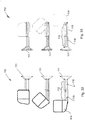
- In order that the invention may be more clearly understood and put into practical effect, reference will now be made to the accompanying drawings wherein:
-
Fig. 1 is a front elevation of a towing mirror according to the invention adapted to be mounted to the right-hand side of the vehicle and viewed from the rear of the vehicle on which it would be mounted in its fully retracted position; -
Fig. 2 is a rear elevation of the towing mirror ofFig. 1 when viewed from the front of the vehicle; -
Fig. 3 is a plan view of the towing mirror ofFig. 1 viewed from above; -
Fig. 4 is a plan view of the towing mirror ofFig. 1 viewed from below; -
Fig. 5 is a side elevation of the towing mirror ofFig. 1 viewed from the outside of the vehicle; -
Fig. 6 is a side elevation of the towing mirror ofFig. 1 viewed from inside the vehicle; -
Fig. 7 is a front elevation of the towing mirror ofFig. 1 viewed from the rear of the vehicle on which it would be mounted in a part extended position; -
Fig. 8 is a rear elevation of the towing mirror ofFig. 1 when viewed from the front of the vehicle in the position ofFig. 7 ; -
Fig. 9 is a plan view of the towing mirror ofFig. 1 viewed from above in the position ofFig. 7 ; -
Fig. 10 is a plan view of the towing mirror ofFig. 1 viewed from below in the position ofFig. 7 ; -
Fig. 11 is a side elevation of the towing mirror ofFig. 1 viewed from the outside of the vehicle in the position ofFig. 7 ; -
Fig. 12 is a side elevation of the towing mirror ofFig. 1 viewed from inside the vehicle in the position ofFig. 7 ; -
Fig. 13 is a pictorial representation of the towing mirror ofFig. 1 from one side in the position ofFig. 7 but removed from its mount; -
Fig. 14 is a pictorial representation of the towing mirror ofFig. 1 from the other side in the position ofFig. 7 but removed from its mount; -
Fig. 15 is a front elevation of the towing mirror ofFig. 1 viewed from the rear of the vehicle on which it would be mounted in a fully extended position; -
Fig. 16 is a rear elevation of the towing mirror ofFig. 1 when viewed from the front of the vehicle in the position ofFig. 15 ; -
Fig. 17 is a plan view of the towing mirror ofFig. 1 viewed from above in the position ofFig. 15 ; -
Fig. 18 is a plan view of the towing mirror ofFig. 1 viewed from below in the position ofFig. 15 ; -
Fig. 19 is a side elevation of the towing mirror ofFig. 1 viewed from the outside of the vehicle in the position ofFig. 15 ; -
Fig. 20 is a side elevation of the towing mirror ofFig. 1 viewed from inside the vehicle in the position ofFig. 15 ; -
Fig. 21 is a pictorial representation of the towing mirror ofFig. 1 from one side in the position cfFig. 15 but removed from its mount; -
Fig. 22 is a pictorial representation of the towing mirror ofFig. 1 from the other side in the position ofFig. 15 but removed from its mount; -
Fig. 23 is a front elevation of the towing mirror ofFig. 1 viewed from the rear of the vehicle on which it would be mounted in an alternative part extended position; -
Fig. 24 is a rear elevation of the towing mirror ofFig. 1 when viewed from the front of the vehicle in the position ofFig. 23 ; -
Fig. 25 is a plan view of the towing mirror ofFig. 1 viewed from above in the position ofFig. 23 ; -
Fig. 26 is a plan view of the towing mirror ofFig. 1 viewed from below in the position ofFig. 23 ; -
Fig. 27 is a side elevation of the towing mirror ofFig. 1 viewed from the outside of the vehicle in the position ofFig. 23 ; -
Fig. 28 is a side elevation of the towing mirror ofFig. 1 viewed from inside the vehicle in the position ofFig. 23 ; -
Fig. 29 is a pictorial representation of the towing mirror ofFig. 1 from one side in the position ofFig. 23 but removed from its mount; -
Fig. 30 is a pictorial representation of the towing mirror ofFig. 1 from the other side in the position ofFig. 23 but removed from its mount; -
Fig. 31 is an enlarged schematic elevation of the towing mirror illustrated inFig. 15 with a slightly different mirror; -
Fig. 32 is a front elevation of another towing mirror according to the invention adapted to be mounted to the left-hand side of the vehicle and viewed from the rear of the vehicle on which it would be mounted intended to show movement of the mirror component from the part extended position to the fully extended position; -
Fig. 33 is a rear elevation of the towing mirror ofFig. 31 in the same positions as inFig. 31 but viewed from the front of the vehicle; and -
Fig. 34 is an exploded plan view from above of yet another towing mirror according to the invention adapted to be mounted to the right-hand side of the vehicle and showing parts making up the various components of the towing mirror. - The towing mirror or
mirror assembly 10 illustrated inFigs. 1 to 30 includes amount 11 adapted to be mounted to the outer skin of the door of a vehicle, anextension component 12 connected at one end to themount 11 by avertical pivot pin 13, and a mirror ormirror component 14 connected to the other end of the extension component by ahorizontal pivot pin 16 which can be more clearly seen inFig 15 . - Advantageously, the
extension component 12 comprises afirst member 18 to which thevertical pivot pin 13 is fixed at its proximal or inner end and asecond member 19 which is slidably mounted on the first component for longitudinal movement relative thereto along ahorizontal axis 20 shown inFig. 1 , that is, towards and away from themount 11 as required. Notably, thepivot pin 13 is engaged in a complementary bore provided in the mount and secured therein by a circlip or similar means (not shown) for pivoting movement relative to the mount about avertical axis 21. Notably, the first member is a substantially rectangular in outer shape and slides in a complementary rectangular shaped cavity in the second member, the rectangular shape of both being such as to prevent relative rotation between the two components about thelongitudinal axis 20. - The
mirror component 14 in turn is mounted to the outer or distal end of thesecond member 19 of the extension component for pivoting movement about ahorizontal axis 23 which extends generally in the direction of travel of the vehicle to which themount 11 is to be secured. - It will be appreciated that the mirror is in the retracted position shown in
Figs. 1 to 6 for normal non-towing driving of the vehicle. In that position, the mirror is relatively close to the vehicle cabin to which the mount is secured with the extension component fully retracted with the first extension member almost fully encompassed by the second extension member while the mirror component is disposed almost fully behind the extension component, that is, in a position most distal to the vehicle cabin. - It will also be appreciated that the mirror is in a first extended position shown in
Figs. 7 to 14 whereby theextension component 12 is a fully extended, that is, with the second extension member drawn along the first extension member so that the mirror component is in a middle disposition further from the vehicle cabin but in the same attitude as shown inFigs. 1 to 6 . - Further, it will also be appreciated that the mirror is in a second or fully extended position shown in
Figs. 15 to 22 whereby theextension component 12 is fully extended as inFigs. 7 to 14 but in the fully extended position the mirror component has been rotated through 90° in a clockwise direction when viewed from the rear of the vehicle thereby placing the mirror component further from the vehicle. This is achieved by thehorizontal pivot pin 16 being mounted in corner portion 31 of the mirror component, that corner portion being the outermost portion when in the retracted position and then becoming the innermost portion when in the extended disposition. - As can be more clearly seen in
Fig. 31 , thehorizontal pivot pin 16 extends from a loweroutermost corner 41 of the second extension member orportion 19 and is arranged so that it fits into arecess 42 provided in the first extension member when the extension component is fully retracted. Advantageously, such arrangement allows theextension component 12 to maximise its slidable length while at the same time maximises the vertical and horizontal extent to which the mirror component can pivot about thehorizontal axis 16 thereby maximising the extension of the towing mirror. It will be appreciated that selection of different shaped mirrors provides for higher or wider vision depending on the circumstances but the minimum width of the retracted mirror assembly is substantially determined by the width of the mirror when in the fully retracted position and that width determines the height of the mirror when in the 90° arc position as shown inFig. 15 or the 180° arc position (not shown). - Various positions of the extension component can be set by way of a spring-loaded detent in one component engaging with a mating seat in the other component. Thus, the extension component might have an inner position seat, and outer position seat and one or two intermediate seats so that any desired one of those positions can be selected. Similarly, a spring-loaded detent can be provided in the mirror component to engage with a 0° arc seat in the outer extension member, a 90° arc seat and a 180° arc seat if desired to achieve the desired purpose.
- The
towing mirror 110 illustrated inFigs. 32 and 33 is similar to the towingmirror 10 illustrated inFigs. 1 to 31 in many respects and consequently, corresponding reference numbers are used to reference corresponding features except prefaced by a "1". The main difference is that theextension component 112 is not pivotally mounted to themount 111. It still comprises afirst extension member 118 and asecond extension member 119 which is slidably mounted onextension member 118, butextension member 118 is immovably fixed to themount 111. That is to say, whereas theextension member 18 inmirror assembly 10 is pivotally mounted to mount 11, in thisparticular mirror assembly 110, there is no pivot action provided for between theextension member 118 and themount 111. However, theextension component 112 comprising theinner member 118 and theouter member 119 operates in much the same manner as in the previous mirror assembly described and themirror component 114 pivots about a horizontal axis relative to theextension member 119 in much the same manner as the previous mirror assembly. - The
towing mirror 210 illustrated inFig. 34 is similar in many respects to the towingmirror 10 illustrated inFigs. 1 to 31 and consequently, corresponding reference numbers are used to reference corresponding features except prefaced by a "2". Thetowing mirror 210 is illustrated inFig. 34 with more detail in respect of the components making up the various parts, but the reference numerals still commence with a "2" for consistency. - The
extension component 212 is shown above the dottedline 225 and themirror component 214 below the dotted line 224, except for a part covering the line and one of the parts described later. Thefirst member 218 forms part of the extension component embraced by the double-dot dashedline 226 and the remaining parts of theextension component 212 form thesecond member 219. - The first member has a
main part 232 covered by a firstforward cover 233 and a firstrearward cover 234 which are clipped together by mating parts or otherwise fastened together by fasteners such as screws or nuts and bolts. The first covers each have a proximal expandedportion 236 and an elongatedistal portion 237 and each cover mates with the other to substantially encapsulate the main part. The man part has apivot assembly 235 for thepivot 213. - The second member has a
forward part 241 andrear part 242 which are fastened together by clips of fasteners to enclose the distal portion of the first member for sliding engagement therewith. A secondforward cover 243 and a secondrearward cover 244 are formed to clip together to cover the forward and rear parts, all being parts of the second member. The clip arrangement for fastening the covers together are arranged internally to provide an outside surface free from screw heads and the like. The rear part has aprotuberance 245 extending rearwardly from the distal end to provide a accommodate a pivot pin (not shown). - The mirror component has a mirror cowling 250 which forms the main structural part, being pivoted to the distal end of the second component by way of the pivot pin associated with the
protuberance 245, the location of the pivot being obstructed by another part described below. Amirror support frame 252 is mounted inside the mirror cowling and is operatively associated with amirror cradle 253. A mirror (not shown) is mounted to the rear side of the mirror cradle and a 2-dimensional pivot assembly 254 is mounted intermediate the mirror cradle and the mirror support frame to provide the aforesaid operative association between the mirror cradle and the mirror support frame. The 2-dimensional pivot assembly provided for up and down and side-to-side rotation of the mirror cradle about one or two pivot points forward of the mirror cradle. - A
lamp assembly 260 is mounted to the upper outer corner of the mirror cowling, anaperture 261 being provided therein to accommodate same. The lamp assembly has forward and rearward facing lamps providing multidirectional indicator lights as hereinbefore described. This is the part mentioned above which in the illustration covers the dotted line and the secondrearward cover 244. - In use, two towing mirrors are provided for a motor vehicle according to the invention, each being opposite handed to the other. The towing mirrors are normally left in their fully retracted position when the vehicle is not towing anything. If a small towed vehicle is hitched to the towing vehicle, such as a trailer or small boat, one or both towing mirrors may be extended to their partially extended position by sliding the second member out from the first member. The first and second members have a spring loaded arrangement locking the second member in either the retracted or the extended position with respect to the first member so that the towing mirror is not inadvertently or unintentionally moved between positions such as by wind action against the towing mirrors when the vehicle is in motion.
- For towing larger vehicles, such as caravans, large boats or other equipment, the towing mirrors may be extended to the full extent by pivoting the mirror outward, again against spring loading which locks the mirror component in either the overlying position (retracted) or the outlying position (extended).
Claims (11)
- A towing mirror (10) including:a mount (11) adapted to be mounted to a vehicle cabin;an extension component (12) including a first member or portion (18) extending from said mount and a second member (19) operatively connected to said first member or portion for sliding movement relative thereto from a retracted position to an extended position; anda mirror component (14) operatively connected to said second member (19) for pivoting movement relative thereto about a generally horizontal axis (23) extending substantially in the intended direction of travel of the vehicle cabin to which the mirror is to be mounted from an inward or retracted position to an outward or extended position.
- A towing mirror (10) according to Claim 1 wherein said extension component (12) is operatively connected at one end to said mount (11) for pivoting movement relative thereto about a generally vertical axis (21).
- A towing mirror (10) according to Claim 1 or Claim 2 wherein the mirror component (14) is arranged to move through an arc of up to 180° about said generally horizontal axis (23) such that in one position at least a substantial part of the mirror component overlies said second member of the extension component and in another position is substantially beyond or outward of said second member (19).
- A towing mirror (10) according to any one of the preceding claims, wherein the mirror component (14) is substantially rectangular in form and said generally horizontal axis (23) is adjacent one end thereof.
- A towing mirror (10) according to Claim 4 wherein the generally horizontal pivot axis (23) is adjacent one corner of the mirror component.
- A towing mirror (10) according to Claim 5 wherein the mirror component (14) is arranged to move through an arc of 90° to the fully extended position wherein the mirror component is substantially above and outside the horizontal pivot axis (23).
- A towing mirror (10) according to any one of Claims 3 to 6 wherein the mirror component (14) is mounted to said second member (19) such that the mirror component (14) is rearward of the second member (19).
- A towing mirror (10) according to any one of the preceding claims wherein the first and second members are elongate members and the second member is arranged to slide longitudinally relative to the first member or portion to thereby move from the retracted position to the extended position.
- A towing mirror (10) according to Claim 8 wherein the first member or portion (18) and the second member (19) are constructed so as to incorporate keying means which prevent the second member rotating relative to the first member or portion through an arc about the longitudinal axis of the first member or portion.
- A towing mirror (10) according to Claim 8 wherein the first member or portion (18) and the second member (19) have complementary noncircular cross-sectional shapes such as rectangular whereby one can slide tightly inside the other without any relative rotational movement.
- A towing mirror (10) according to Claim 8 wherein said keying means include a longitudinal protrusion and a complementary longitudinal recess respectively on the first member or portion and the second member to prevent relative rotational movement therebetween.
Applications Claiming Priority (2)
| Application Number | Priority Date | Filing Date | Title |
|---|---|---|---|
| AU2016904946A AU2016904946A0 (en) | 2016-12-01 | Vehicle mirrors | |
| PCT/AU2017/051320 WO2018098530A1 (en) | 2016-12-01 | 2017-11-30 | Vehicle mirrors |
Publications (3)
| Publication Number | Publication Date |
|---|---|
| EP3548338A1 EP3548338A1 (en) | 2019-10-09 |
| EP3548338A4 EP3548338A4 (en) | 2020-05-20 |
| EP3548338B1 true EP3548338B1 (en) | 2021-05-19 |
Family
ID=62240957
Family Applications (1)
| Application Number | Title | Priority Date | Filing Date |
|---|---|---|---|
| EP17876790.1A Active EP3548338B1 (en) | 2016-12-01 | 2017-11-30 | Vehicle mirrors |
Country Status (9)
| Country | Link |
|---|---|
| US (1) | US11472342B2 (en) |
| EP (1) | EP3548338B1 (en) |
| CN (2) | CN110177712A (en) |
| AU (4) | AU2017268622A1 (en) |
| CA (1) | CA3090433A1 (en) |
| ES (1) | ES2883419T3 (en) |
| NZ (1) | NZ754915A (en) |
| WO (1) | WO2018098530A1 (en) |
| ZA (1) | ZA201904166B (en) |
Families Citing this family (5)
| Publication number | Priority date | Publication date | Assignee | Title |
|---|---|---|---|---|
| IT201800007201A1 (en) * | 2018-07-13 | 2020-01-13 | SUPPORT FOR CONNECTING A REAR VIEW MIRROR TO A CORRESPONDING VEHICLE | |
| WO2021022335A1 (en) | 2019-08-08 | 2021-02-11 | Shane Miles | Vehicle mirrors |
| CN114555421B (en) * | 2019-10-31 | 2024-03-26 | 金泰克斯公司 | Rotatable external mirror with imager assembly |
| US11007939B1 (en) * | 2019-12-20 | 2021-05-18 | Motherson Innovations Company Limited | Support assembly for mirror |
| CN113367493B (en) * | 2021-06-11 | 2023-06-02 | 张震 | Hardware connecting piece capable of realizing automatic overturning of cabinet mirror |
Family Cites Families (22)
| Publication number | Priority date | Publication date | Assignee | Title |
|---|---|---|---|---|
| US2241866A (en) * | 1940-06-25 | 1941-05-13 | Paul W Needham | Rear view mirror |
| US2596632A (en) * | 1946-02-05 | 1952-05-13 | Whitehead Stamping Company | Mirror supporting means |
| US2717531A (en) * | 1952-10-10 | 1955-09-13 | John F Schenck | Telescoping vehicle rear view mirror assembly |
| US3482811A (en) * | 1967-07-12 | 1969-12-09 | Lawson J Zent | Device for mounting a mirror on an automobile |
| IT7853734U1 (en) | 1978-09-28 | 1980-03-28 | Vitaloni Spa | EXTERNAL REARVIEW MIRROR, ESPECIALLY FOR MOTORHOME VEHICLES, COMMERCIAL VEHICLES AND SIMILAR. |
| US4730913A (en) * | 1986-08-04 | 1988-03-15 | Lee H. Boothe | Adjustable mount for lateral rear view mirror |
| US4711538A (en) * | 1986-09-29 | 1987-12-08 | Creative Sales & Mfg. Co., Inc. | Adjustable support device for vehicle side view mirror |
| US6024459A (en) * | 1997-04-11 | 2000-02-15 | Lewis; Jimmie L. | Extendable rearview mirror |
| US6820987B1 (en) * | 1997-04-11 | 2004-11-23 | Jimmie L. Lewis | Extendable rearview mirror |
| MXPA01004348A (en) * | 1998-11-02 | 2002-04-24 | Magna Mirror Systems Inc | Coordinated pivoting and extending vehicle mirror. |
| ATE326711T1 (en) * | 1999-04-09 | 2006-06-15 | Magna Mirror Systems Inc | EXTENDABLE AND SWIVELING REARVIEW MIRROR ARRANGEMENT |
| US6672726B1 (en) * | 1999-06-21 | 2004-01-06 | Ian Boddy | Extending and rotating rearview mirror assembly |
| US6239928B1 (en) * | 1999-09-20 | 2001-05-29 | Donnelly Corporation | Extendable exterior rearview mirror assembly for vehicles |
| US6116743A (en) * | 1999-09-20 | 2000-09-12 | Donnelly Corporation | Extendable exterior rearview mirror assembly for vehicles |
| US6394616B1 (en) * | 2000-04-10 | 2002-05-28 | Magna Mirror Systems, Inc. | Powered screw drive extendable and pivotal rearview mirror assembly |
| US6851813B2 (en) * | 2001-07-13 | 2005-02-08 | Donnelly Corporation | Tow mirror assembly for vehicles |
| US7350931B1 (en) | 2004-06-30 | 2008-04-01 | Magna Donnelly Mirrors North America Llc | Vehicular pivot mirror |
| US7441910B1 (en) | 2004-06-30 | 2008-10-28 | Magna Mirrors Of America, Inc. | Vehicular pivot mirror |
| US7490946B1 (en) | 2005-10-28 | 2009-02-17 | Magna Mirrors Of America, Inc. | Main mirror with pivot connection |
| US7594731B2 (en) | 2007-06-15 | 2009-09-29 | Visiocorp Patents S.A.R.L. | Side mirror assembly for a motor vehicle |
| US9057833B2 (en) * | 2012-09-28 | 2015-06-16 | Nissan North America, Inc. | Vehicle mirror assembly |
| US9969333B2 (en) * | 2016-05-13 | 2018-05-15 | Deere & Company | Extendable mirror assembly for a vehicle |
-
2017
- 2017-11-30 CA CA3090433A patent/CA3090433A1/en active Pending
- 2017-11-30 AU AU2017268622A patent/AU2017268622A1/en not_active Abandoned
- 2017-11-30 AU AU2017369741A patent/AU2017369741B2/en active Active
- 2017-11-30 CN CN201780083354.9A patent/CN110177712A/en active Pending
- 2017-11-30 ES ES17876790T patent/ES2883419T3/en active Active
- 2017-11-30 US US16/465,924 patent/US11472342B2/en active Active
- 2017-11-30 EP EP17876790.1A patent/EP3548338B1/en active Active
- 2017-11-30 WO PCT/AU2017/051320 patent/WO2018098530A1/en not_active Ceased
- 2017-11-30 NZ NZ754915A patent/NZ754915A/en unknown
- 2017-12-01 CN CN201721652844.XU patent/CN208264113U/en active Active
-
2019
- 2019-06-26 ZA ZA2019/04166A patent/ZA201904166B/en unknown
-
2023
- 2023-11-08 AU AU2023263483A patent/AU2023263483A1/en not_active Abandoned
-
2025
- 2025-10-01 AU AU2025242150A patent/AU2025242150A1/en active Pending
Also Published As
| Publication number | Publication date |
|---|---|
| US20190291644A1 (en) | 2019-09-26 |
| AU2023263483A1 (en) | 2023-11-30 |
| WO2018098530A1 (en) | 2018-06-07 |
| AU2017369741A1 (en) | 2019-07-18 |
| CA3090433A1 (en) | 2018-06-07 |
| CN110177712A (en) | 2019-08-27 |
| ES2883419T3 (en) | 2021-12-07 |
| AU2025242150A1 (en) | 2025-10-23 |
| NZ754915A (en) | 2023-06-30 |
| AU2017268622A1 (en) | 2018-06-21 |
| EP3548338A1 (en) | 2019-10-09 |
| ZA201904166B (en) | 2022-02-23 |
| AU2017369741B2 (en) | 2023-09-28 |
| US11472342B2 (en) | 2022-10-18 |
| EP3548338A4 (en) | 2020-05-20 |
| CN208264113U (en) | 2018-12-21 |
Similar Documents
| Publication | Publication Date | Title |
|---|---|---|
| EP3548338B1 (en) | Vehicle mirrors | |
| US10099618B2 (en) | Exterior rearview mirror assembly | |
| US11325535B2 (en) | Exterior rearview mirror assembly | |
| US20030122929A1 (en) | Vehicular camera system | |
| US7216993B2 (en) | Foldable vehicle external mirror having auxiliary mirror | |
| US6497491B2 (en) | Extendable mirror | |
| US4832476A (en) | Blind spot viewing mirror system | |
| US6511189B1 (en) | Interchangeable mirror scalp for trailer towing | |
| US5748395A (en) | Rear view mirror with stowable dual view mirror | |
| EP3415371B1 (en) | Side rearview vision assembly with telescoping head | |
| CN112706844B (en) | Reversing camera that can be stowed into the movable spoiler | |
| US20220396206A1 (en) | Motorised Vehicle Mirrors | |
| US6445506B1 (en) | Head up display system | |
| US20040150900A1 (en) | Detachable remotely-adjustable extension mirror system | |
| WO2005039926A2 (en) | Rear view device for vehicles | |
| GB2188013A (en) | Rear view mirror | |
| WO2001028814A2 (en) | Interchangeable mirror scalp for trailer towing | |
| AU2022100051A4 (en) | Vehicle mirrors | |
| EP1334873A1 (en) | Vehicle rear view mirror assembly | |
| CN211468313U (en) | Automobile interior rear-view mirror with turnover mechanism | |
| AU2022202216A1 (en) | Vehicle Mirrors | |
| US20130050859A1 (en) | Rearward and forward viewing vehicular mirror assembly | |
| UA133269U (en) | REAR VIDEO SYSTEM FOR A VEHICLE | |
| JPH11310080A (en) | Lane-change mirror | |
| HUP9904374A2 (en) | Optical rear vision device for cars |
Legal Events
| Date | Code | Title | Description |
|---|---|---|---|
| STAA | Information on the status of an ep patent application or granted ep patent |
Free format text: STATUS: THE INTERNATIONAL PUBLICATION HAS BEEN MADE |
|
| PUAI | Public reference made under article 153(3) epc to a published international application that has entered the european phase |
Free format text: ORIGINAL CODE: 0009012 |
|
| STAA | Information on the status of an ep patent application or granted ep patent |
Free format text: STATUS: REQUEST FOR EXAMINATION WAS MADE |
|
| 17P | Request for examination filed |
Effective date: 20190628 |
|
| AK | Designated contracting states |
Kind code of ref document: A1 Designated state(s): AL AT BE BG CH CY CZ DE DK EE ES FI FR GB GR HR HU IE IS IT LI LT LU LV MC MK MT NL NO PL PT RO RS SE SI SK SM TR |
|
| AX | Request for extension of the european patent |
Extension state: BA ME |
|
| DAV | Request for validation of the european patent (deleted) | ||
| DAX | Request for extension of the european patent (deleted) | ||
| A4 | Supplementary search report drawn up and despatched |
Effective date: 20200420 |
|
| RIC1 | Information provided on ipc code assigned before grant |
Ipc: B60R 1/08 20060101ALI20200414BHEP Ipc: B60R 1/06 20060101ALI20200414BHEP Ipc: B60R 1/02 20060101AFI20200414BHEP Ipc: B60R 1/078 20060101ALI20200414BHEP |
|
| GRAP | Despatch of communication of intention to grant a patent |
Free format text: ORIGINAL CODE: EPIDOSNIGR1 |
|
| STAA | Information on the status of an ep patent application or granted ep patent |
Free format text: STATUS: GRANT OF PATENT IS INTENDED |
|
| INTG | Intention to grant announced |
Effective date: 20210205 |
|
| GRAS | Grant fee paid |
Free format text: ORIGINAL CODE: EPIDOSNIGR3 |
|
| GRAA | (expected) grant |
Free format text: ORIGINAL CODE: 0009210 |
|
| STAA | Information on the status of an ep patent application or granted ep patent |
Free format text: STATUS: THE PATENT HAS BEEN GRANTED |
|
| AK | Designated contracting states |
Kind code of ref document: B1 Designated state(s): AL AT BE BG CH CY CZ DE DK EE ES FI FR GB GR HR HU IE IS IT LI LT LU LV MC MK MT NL NO PL PT RO RS SE SI SK SM TR |
|
| REG | Reference to a national code |
Ref country code: GB Ref legal event code: FG4D |
|
| REG | Reference to a national code |
Ref country code: CH Ref legal event code: EP |
|
| REG | Reference to a national code |
Ref country code: DE Ref legal event code: R096 Ref document number: 602017039023 Country of ref document: DE |
|
| REG | Reference to a national code |
Ref country code: AT Ref legal event code: REF Ref document number: 1393675 Country of ref document: AT Kind code of ref document: T Effective date: 20210615 |
|
| REG | Reference to a national code |
Ref country code: IE Ref legal event code: FG4D |
|
| REG | Reference to a national code |
Ref country code: NL Ref legal event code: FP |
|
| REG | Reference to a national code |
Ref country code: LT Ref legal event code: MG9D |
|
| REG | Reference to a national code |
Ref country code: AT Ref legal event code: MK05 Ref document number: 1393675 Country of ref document: AT Kind code of ref document: T Effective date: 20210519 |
|
| PG25 | Lapsed in a contracting state [announced via postgrant information from national office to epo] |
Ref country code: HR Free format text: LAPSE BECAUSE OF FAILURE TO SUBMIT A TRANSLATION OF THE DESCRIPTION OR TO PAY THE FEE WITHIN THE PRESCRIBED TIME-LIMIT Effective date: 20210519 Ref country code: AT Free format text: LAPSE BECAUSE OF FAILURE TO SUBMIT A TRANSLATION OF THE DESCRIPTION OR TO PAY THE FEE WITHIN THE PRESCRIBED TIME-LIMIT Effective date: 20210519 Ref country code: BG Free format text: LAPSE BECAUSE OF FAILURE TO SUBMIT A TRANSLATION OF THE DESCRIPTION OR TO PAY THE FEE WITHIN THE PRESCRIBED TIME-LIMIT Effective date: 20210819 Ref country code: LT Free format text: LAPSE BECAUSE OF FAILURE TO SUBMIT A TRANSLATION OF THE DESCRIPTION OR TO PAY THE FEE WITHIN THE PRESCRIBED TIME-LIMIT Effective date: 20210519 Ref country code: FI Free format text: LAPSE BECAUSE OF FAILURE TO SUBMIT A TRANSLATION OF THE DESCRIPTION OR TO PAY THE FEE WITHIN THE PRESCRIBED TIME-LIMIT Effective date: 20210519 |
|
| PG25 | Lapsed in a contracting state [announced via postgrant information from national office to epo] |
Ref country code: PT Free format text: LAPSE BECAUSE OF FAILURE TO SUBMIT A TRANSLATION OF THE DESCRIPTION OR TO PAY THE FEE WITHIN THE PRESCRIBED TIME-LIMIT Effective date: 20210920 Ref country code: NO Free format text: LAPSE BECAUSE OF FAILURE TO SUBMIT A TRANSLATION OF THE DESCRIPTION OR TO PAY THE FEE WITHIN THE PRESCRIBED TIME-LIMIT Effective date: 20210819 Ref country code: LV Free format text: LAPSE BECAUSE OF FAILURE TO SUBMIT A TRANSLATION OF THE DESCRIPTION OR TO PAY THE FEE WITHIN THE PRESCRIBED TIME-LIMIT Effective date: 20210519 Ref country code: PL Free format text: LAPSE BECAUSE OF FAILURE TO SUBMIT A TRANSLATION OF THE DESCRIPTION OR TO PAY THE FEE WITHIN THE PRESCRIBED TIME-LIMIT Effective date: 20210519 Ref country code: RS Free format text: LAPSE BECAUSE OF FAILURE TO SUBMIT A TRANSLATION OF THE DESCRIPTION OR TO PAY THE FEE WITHIN THE PRESCRIBED TIME-LIMIT Effective date: 20210519 Ref country code: SE Free format text: LAPSE BECAUSE OF FAILURE TO SUBMIT A TRANSLATION OF THE DESCRIPTION OR TO PAY THE FEE WITHIN THE PRESCRIBED TIME-LIMIT Effective date: 20210519 Ref country code: GR Free format text: LAPSE BECAUSE OF FAILURE TO SUBMIT A TRANSLATION OF THE DESCRIPTION OR TO PAY THE FEE WITHIN THE PRESCRIBED TIME-LIMIT Effective date: 20210820 Ref country code: IS Free format text: LAPSE BECAUSE OF FAILURE TO SUBMIT A TRANSLATION OF THE DESCRIPTION OR TO PAY THE FEE WITHIN THE PRESCRIBED TIME-LIMIT Effective date: 20210919 |
|
| REG | Reference to a national code |
Ref country code: ES Ref legal event code: FG2A Ref document number: 2883419 Country of ref document: ES Kind code of ref document: T3 Effective date: 20211207 |
|
| PG25 | Lapsed in a contracting state [announced via postgrant information from national office to epo] |
Ref country code: SM Free format text: LAPSE BECAUSE OF FAILURE TO SUBMIT A TRANSLATION OF THE DESCRIPTION OR TO PAY THE FEE WITHIN THE PRESCRIBED TIME-LIMIT Effective date: 20210519 Ref country code: SK Free format text: LAPSE BECAUSE OF FAILURE TO SUBMIT A TRANSLATION OF THE DESCRIPTION OR TO PAY THE FEE WITHIN THE PRESCRIBED TIME-LIMIT Effective date: 20210519 Ref country code: EE Free format text: LAPSE BECAUSE OF FAILURE TO SUBMIT A TRANSLATION OF THE DESCRIPTION OR TO PAY THE FEE WITHIN THE PRESCRIBED TIME-LIMIT Effective date: 20210519 Ref country code: RO Free format text: LAPSE BECAUSE OF FAILURE TO SUBMIT A TRANSLATION OF THE DESCRIPTION OR TO PAY THE FEE WITHIN THE PRESCRIBED TIME-LIMIT Effective date: 20210519 Ref country code: DK Free format text: LAPSE BECAUSE OF FAILURE TO SUBMIT A TRANSLATION OF THE DESCRIPTION OR TO PAY THE FEE WITHIN THE PRESCRIBED TIME-LIMIT Effective date: 20210519 Ref country code: CZ Free format text: LAPSE BECAUSE OF FAILURE TO SUBMIT A TRANSLATION OF THE DESCRIPTION OR TO PAY THE FEE WITHIN THE PRESCRIBED TIME-LIMIT Effective date: 20210519 |
|
| REG | Reference to a national code |
Ref country code: DE Ref legal event code: R097 Ref document number: 602017039023 Country of ref document: DE |
|
| PLBE | No opposition filed within time limit |
Free format text: ORIGINAL CODE: 0009261 |
|
| STAA | Information on the status of an ep patent application or granted ep patent |
Free format text: STATUS: NO OPPOSITION FILED WITHIN TIME LIMIT |
|
| 26N | No opposition filed |
Effective date: 20220222 |
|
| PG25 | Lapsed in a contracting state [announced via postgrant information from national office to epo] |
Ref country code: IS Free format text: LAPSE BECAUSE OF FAILURE TO SUBMIT A TRANSLATION OF THE DESCRIPTION OR TO PAY THE FEE WITHIN THE PRESCRIBED TIME-LIMIT Effective date: 20210919 Ref country code: AL Free format text: LAPSE BECAUSE OF FAILURE TO SUBMIT A TRANSLATION OF THE DESCRIPTION OR TO PAY THE FEE WITHIN THE PRESCRIBED TIME-LIMIT Effective date: 20210519 |
|
| PG25 | Lapsed in a contracting state [announced via postgrant information from national office to epo] |
Ref country code: MC Free format text: LAPSE BECAUSE OF FAILURE TO SUBMIT A TRANSLATION OF THE DESCRIPTION OR TO PAY THE FEE WITHIN THE PRESCRIBED TIME-LIMIT Effective date: 20210519 |
|
| REG | Reference to a national code |
Ref country code: CH Ref legal event code: PL |
|
| PG25 | Lapsed in a contracting state [announced via postgrant information from national office to epo] |
Ref country code: LU Free format text: LAPSE BECAUSE OF NON-PAYMENT OF DUE FEES Effective date: 20211130 Ref country code: IT Free format text: LAPSE BECAUSE OF FAILURE TO SUBMIT A TRANSLATION OF THE DESCRIPTION OR TO PAY THE FEE WITHIN THE PRESCRIBED TIME-LIMIT Effective date: 20210519 |
|
| PG25 | Lapsed in a contracting state [announced via postgrant information from national office to epo] |
Ref country code: LI Free format text: LAPSE BECAUSE OF NON-PAYMENT OF DUE FEES Effective date: 20211130 Ref country code: CH Free format text: LAPSE BECAUSE OF NON-PAYMENT OF DUE FEES Effective date: 20211130 |
|
| PG25 | Lapsed in a contracting state [announced via postgrant information from national office to epo] |
Ref country code: IE Free format text: LAPSE BECAUSE OF NON-PAYMENT OF DUE FEES Effective date: 20211130 |
|
| P01 | Opt-out of the competence of the unified patent court (upc) registered |
Effective date: 20230524 |
|
| PG25 | Lapsed in a contracting state [announced via postgrant information from national office to epo] |
Ref country code: CY Free format text: LAPSE BECAUSE OF FAILURE TO SUBMIT A TRANSLATION OF THE DESCRIPTION OR TO PAY THE FEE WITHIN THE PRESCRIBED TIME-LIMIT Effective date: 20210519 |
|
| PG25 | Lapsed in a contracting state [announced via postgrant information from national office to epo] |
Ref country code: HU Free format text: LAPSE BECAUSE OF FAILURE TO SUBMIT A TRANSLATION OF THE DESCRIPTION OR TO PAY THE FEE WITHIN THE PRESCRIBED TIME-LIMIT; INVALID AB INITIO Effective date: 20171130 |
|
| PG25 | Lapsed in a contracting state [announced via postgrant information from national office to epo] |
Ref country code: MK Free format text: LAPSE BECAUSE OF FAILURE TO SUBMIT A TRANSLATION OF THE DESCRIPTION OR TO PAY THE FEE WITHIN THE PRESCRIBED TIME-LIMIT Effective date: 20210519 |
|
| PG25 | Lapsed in a contracting state [announced via postgrant information from national office to epo] |
Ref country code: MT Free format text: LAPSE BECAUSE OF FAILURE TO SUBMIT A TRANSLATION OF THE DESCRIPTION OR TO PAY THE FEE WITHIN THE PRESCRIBED TIME-LIMIT Effective date: 20210519 |
|
| PG25 | Lapsed in a contracting state [announced via postgrant information from national office to epo] |
Ref country code: TR Free format text: LAPSE BECAUSE OF FAILURE TO SUBMIT A TRANSLATION OF THE DESCRIPTION OR TO PAY THE FEE WITHIN THE PRESCRIBED TIME-LIMIT Effective date: 20210519 |
|
| PGFP | Annual fee paid to national office [announced via postgrant information from national office to epo] |
Ref country code: NL Payment date: 20251119 Year of fee payment: 9 |
|
| PGFP | Annual fee paid to national office [announced via postgrant information from national office to epo] |
Ref country code: DE Payment date: 20251119 Year of fee payment: 9 |
|
| PGFP | Annual fee paid to national office [announced via postgrant information from national office to epo] |
Ref country code: GB Payment date: 20251121 Year of fee payment: 9 |
|
| PGFP | Annual fee paid to national office [announced via postgrant information from national office to epo] |
Ref country code: FR Payment date: 20251126 Year of fee payment: 9 |
|
| PGFP | Annual fee paid to national office [announced via postgrant information from national office to epo] |
Ref country code: BE Payment date: 20251119 Year of fee payment: 9 |
|
| PGFP | Annual fee paid to national office [announced via postgrant information from national office to epo] |
Ref country code: ES Payment date: 20251229 Year of fee payment: 9 |