EP3548322B1 - Electric axle transmission for electric and hybrid electric vehicles - Google Patents
Electric axle transmission for electric and hybrid electric vehicles Download PDFInfo
- Publication number
- EP3548322B1 EP3548322B1 EP17876607.7A EP17876607A EP3548322B1 EP 3548322 B1 EP3548322 B1 EP 3548322B1 EP 17876607 A EP17876607 A EP 17876607A EP 3548322 B1 EP3548322 B1 EP 3548322B1
- Authority
- EP
- European Patent Office
- Prior art keywords
- electric
- planetary gear
- coupled
- motor
- drivetrain
- Prior art date
- Legal status (The legal status is an assumption and is not a legal conclusion. Google has not performed a legal analysis and makes no representation as to the accuracy of the status listed.)
- Active
Links
Images

Classifications
-
- F—MECHANICAL ENGINEERING; LIGHTING; HEATING; WEAPONS; BLASTING
- F16—ENGINEERING ELEMENTS AND UNITS; GENERAL MEASURES FOR PRODUCING AND MAINTAINING EFFECTIVE FUNCTIONING OF MACHINES OR INSTALLATIONS; THERMAL INSULATION IN GENERAL
- F16H—GEARING
- F16H1/00—Toothed gearings for conveying rotary motion
- F16H1/28—Toothed gearings for conveying rotary motion with gears having orbital motion
- F16H1/46—Systems consisting of a plurality of gear trains each with orbital gears, i.e. systems having three or more central gears
-
- B—PERFORMING OPERATIONS; TRANSPORTING
- B60—VEHICLES IN GENERAL
- B60K—ARRANGEMENT OR MOUNTING OF PROPULSION UNITS OR OF TRANSMISSIONS IN VEHICLES; ARRANGEMENT OR MOUNTING OF PLURAL DIVERSE PRIME-MOVERS IN VEHICLES; AUXILIARY DRIVES FOR VEHICLES; INSTRUMENTATION OR DASHBOARDS FOR VEHICLES; ARRANGEMENTS IN CONNECTION WITH COOLING, AIR INTAKE, GAS EXHAUST OR FUEL SUPPLY OF PROPULSION UNITS IN VEHICLES
- B60K7/00—Disposition of motor in, or adjacent to, traction wheel
- B60K7/0007—Disposition of motor in, or adjacent to, traction wheel the motor being electric
-
- B—PERFORMING OPERATIONS; TRANSPORTING
- B60—VEHICLES IN GENERAL
- B60K—ARRANGEMENT OR MOUNTING OF PROPULSION UNITS OR OF TRANSMISSIONS IN VEHICLES; ARRANGEMENT OR MOUNTING OF PLURAL DIVERSE PRIME-MOVERS IN VEHICLES; AUXILIARY DRIVES FOR VEHICLES; INSTRUMENTATION OR DASHBOARDS FOR VEHICLES; ARRANGEMENTS IN CONNECTION WITH COOLING, AIR INTAKE, GAS EXHAUST OR FUEL SUPPLY OF PROPULSION UNITS IN VEHICLES
- B60K1/00—Arrangement or mounting of electrical propulsion units
-
- B—PERFORMING OPERATIONS; TRANSPORTING
- B60—VEHICLES IN GENERAL
- B60K—ARRANGEMENT OR MOUNTING OF PROPULSION UNITS OR OF TRANSMISSIONS IN VEHICLES; ARRANGEMENT OR MOUNTING OF PLURAL DIVERSE PRIME-MOVERS IN VEHICLES; AUXILIARY DRIVES FOR VEHICLES; INSTRUMENTATION OR DASHBOARDS FOR VEHICLES; ARRANGEMENTS IN CONNECTION WITH COOLING, AIR INTAKE, GAS EXHAUST OR FUEL SUPPLY OF PROPULSION UNITS IN VEHICLES
- B60K17/00—Arrangement or mounting of transmissions in vehicles
- B60K17/02—Arrangement or mounting of transmissions in vehicles characterised by arrangement, location, or kind of clutch
-
- B—PERFORMING OPERATIONS; TRANSPORTING
- B60—VEHICLES IN GENERAL
- B60K—ARRANGEMENT OR MOUNTING OF PROPULSION UNITS OR OF TRANSMISSIONS IN VEHICLES; ARRANGEMENT OR MOUNTING OF PLURAL DIVERSE PRIME-MOVERS IN VEHICLES; AUXILIARY DRIVES FOR VEHICLES; INSTRUMENTATION OR DASHBOARDS FOR VEHICLES; ARRANGEMENTS IN CONNECTION WITH COOLING, AIR INTAKE, GAS EXHAUST OR FUEL SUPPLY OF PROPULSION UNITS IN VEHICLES
- B60K17/00—Arrangement or mounting of transmissions in vehicles
- B60K17/04—Arrangement or mounting of transmissions in vehicles characterised by arrangement, location or kind of gearing
-
- B—PERFORMING OPERATIONS; TRANSPORTING
- B60—VEHICLES IN GENERAL
- B60K—ARRANGEMENT OR MOUNTING OF PROPULSION UNITS OR OF TRANSMISSIONS IN VEHICLES; ARRANGEMENT OR MOUNTING OF PLURAL DIVERSE PRIME-MOVERS IN VEHICLES; AUXILIARY DRIVES FOR VEHICLES; INSTRUMENTATION OR DASHBOARDS FOR VEHICLES; ARRANGEMENTS IN CONNECTION WITH COOLING, AIR INTAKE, GAS EXHAUST OR FUEL SUPPLY OF PROPULSION UNITS IN VEHICLES
- B60K17/00—Arrangement or mounting of transmissions in vehicles
- B60K17/04—Arrangement or mounting of transmissions in vehicles characterised by arrangement, location or kind of gearing
- B60K17/043—Transmission unit disposed in on near the vehicle wheel, or between the differential gear unit and the wheel
- B60K17/046—Transmission unit disposed in on near the vehicle wheel, or between the differential gear unit and the wheel with planetary gearing having orbital motion
-
- B—PERFORMING OPERATIONS; TRANSPORTING
- B60—VEHICLES IN GENERAL
- B60K—ARRANGEMENT OR MOUNTING OF PROPULSION UNITS OR OF TRANSMISSIONS IN VEHICLES; ARRANGEMENT OR MOUNTING OF PLURAL DIVERSE PRIME-MOVERS IN VEHICLES; AUXILIARY DRIVES FOR VEHICLES; INSTRUMENTATION OR DASHBOARDS FOR VEHICLES; ARRANGEMENTS IN CONNECTION WITH COOLING, AIR INTAKE, GAS EXHAUST OR FUEL SUPPLY OF PROPULSION UNITS IN VEHICLES
- B60K17/00—Arrangement or mounting of transmissions in vehicles
- B60K17/04—Arrangement or mounting of transmissions in vehicles characterised by arrangement, location or kind of gearing
- B60K17/06—Arrangement or mounting of transmissions in vehicles characterised by arrangement, location or kind of gearing of change-speed gearing
-
- B—PERFORMING OPERATIONS; TRANSPORTING
- B60—VEHICLES IN GENERAL
- B60K—ARRANGEMENT OR MOUNTING OF PROPULSION UNITS OR OF TRANSMISSIONS IN VEHICLES; ARRANGEMENT OR MOUNTING OF PLURAL DIVERSE PRIME-MOVERS IN VEHICLES; AUXILIARY DRIVES FOR VEHICLES; INSTRUMENTATION OR DASHBOARDS FOR VEHICLES; ARRANGEMENTS IN CONNECTION WITH COOLING, AIR INTAKE, GAS EXHAUST OR FUEL SUPPLY OF PROPULSION UNITS IN VEHICLES
- B60K6/00—Arrangement or mounting of plural diverse prime-movers for mutual or common propulsion, e.g. hybrid propulsion systems comprising electric motors and internal combustion engines
- B60K6/20—Arrangement or mounting of plural diverse prime-movers for mutual or common propulsion, e.g. hybrid propulsion systems comprising electric motors and internal combustion engines the prime-movers consisting of electric motors and internal combustion engines, e.g. HEVs
- B60K6/22—Arrangement or mounting of plural diverse prime-movers for mutual or common propulsion, e.g. hybrid propulsion systems comprising electric motors and internal combustion engines the prime-movers consisting of electric motors and internal combustion engines, e.g. HEVs characterised by apparatus, components or means specially adapted for HEVs
- B60K6/26—Arrangement or mounting of plural diverse prime-movers for mutual or common propulsion, e.g. hybrid propulsion systems comprising electric motors and internal combustion engines the prime-movers consisting of electric motors and internal combustion engines, e.g. HEVs characterised by apparatus, components or means specially adapted for HEVs characterised by the motors or the generators
-
- B—PERFORMING OPERATIONS; TRANSPORTING
- B60—VEHICLES IN GENERAL
- B60K—ARRANGEMENT OR MOUNTING OF PROPULSION UNITS OR OF TRANSMISSIONS IN VEHICLES; ARRANGEMENT OR MOUNTING OF PLURAL DIVERSE PRIME-MOVERS IN VEHICLES; AUXILIARY DRIVES FOR VEHICLES; INSTRUMENTATION OR DASHBOARDS FOR VEHICLES; ARRANGEMENTS IN CONNECTION WITH COOLING, AIR INTAKE, GAS EXHAUST OR FUEL SUPPLY OF PROPULSION UNITS IN VEHICLES
- B60K6/00—Arrangement or mounting of plural diverse prime-movers for mutual or common propulsion, e.g. hybrid propulsion systems comprising electric motors and internal combustion engines
- B60K6/20—Arrangement or mounting of plural diverse prime-movers for mutual or common propulsion, e.g. hybrid propulsion systems comprising electric motors and internal combustion engines the prime-movers consisting of electric motors and internal combustion engines, e.g. HEVs
- B60K6/22—Arrangement or mounting of plural diverse prime-movers for mutual or common propulsion, e.g. hybrid propulsion systems comprising electric motors and internal combustion engines the prime-movers consisting of electric motors and internal combustion engines, e.g. HEVs characterised by apparatus, components or means specially adapted for HEVs
- B60K6/36—Arrangement or mounting of plural diverse prime-movers for mutual or common propulsion, e.g. hybrid propulsion systems comprising electric motors and internal combustion engines the prime-movers consisting of electric motors and internal combustion engines, e.g. HEVs characterised by apparatus, components or means specially adapted for HEVs characterised by the transmission gearings
- B60K6/365—Arrangement or mounting of plural diverse prime-movers for mutual or common propulsion, e.g. hybrid propulsion systems comprising electric motors and internal combustion engines the prime-movers consisting of electric motors and internal combustion engines, e.g. HEVs characterised by apparatus, components or means specially adapted for HEVs characterised by the transmission gearings with the gears having orbital motion
-
- F—MECHANICAL ENGINEERING; LIGHTING; HEATING; WEAPONS; BLASTING
- F16—ENGINEERING ELEMENTS AND UNITS; GENERAL MEASURES FOR PRODUCING AND MAINTAINING EFFECTIVE FUNCTIONING OF MACHINES OR INSTALLATIONS; THERMAL INSULATION IN GENERAL
- F16H—GEARING
- F16H3/00—Toothed gearings for conveying rotary motion with variable gear ratio or for reversing rotary motion
- F16H3/44—Toothed gearings for conveying rotary motion with variable gear ratio or for reversing rotary motion using gears having orbital motion
-
- F—MECHANICAL ENGINEERING; LIGHTING; HEATING; WEAPONS; BLASTING
- F16—ENGINEERING ELEMENTS AND UNITS; GENERAL MEASURES FOR PRODUCING AND MAINTAINING EFFECTIVE FUNCTIONING OF MACHINES OR INSTALLATIONS; THERMAL INSULATION IN GENERAL
- F16H—GEARING
- F16H57/00—General details of gearing
- F16H57/08—General details of gearing of gearings with members having orbital motion
- F16H57/10—Braking arrangements
-
- B—PERFORMING OPERATIONS; TRANSPORTING
- B60—VEHICLES IN GENERAL
- B60K—ARRANGEMENT OR MOUNTING OF PROPULSION UNITS OR OF TRANSMISSIONS IN VEHICLES; ARRANGEMENT OR MOUNTING OF PLURAL DIVERSE PRIME-MOVERS IN VEHICLES; AUXILIARY DRIVES FOR VEHICLES; INSTRUMENTATION OR DASHBOARDS FOR VEHICLES; ARRANGEMENTS IN CONNECTION WITH COOLING, AIR INTAKE, GAS EXHAUST OR FUEL SUPPLY OF PROPULSION UNITS IN VEHICLES
- B60K1/00—Arrangement or mounting of electrical propulsion units
- B60K1/02—Arrangement or mounting of electrical propulsion units comprising more than one electric motor
-
- B—PERFORMING OPERATIONS; TRANSPORTING
- B60—VEHICLES IN GENERAL
- B60K—ARRANGEMENT OR MOUNTING OF PROPULSION UNITS OR OF TRANSMISSIONS IN VEHICLES; ARRANGEMENT OR MOUNTING OF PLURAL DIVERSE PRIME-MOVERS IN VEHICLES; AUXILIARY DRIVES FOR VEHICLES; INSTRUMENTATION OR DASHBOARDS FOR VEHICLES; ARRANGEMENTS IN CONNECTION WITH COOLING, AIR INTAKE, GAS EXHAUST OR FUEL SUPPLY OF PROPULSION UNITS IN VEHICLES
- B60K1/00—Arrangement or mounting of electrical propulsion units
- B60K2001/001—Arrangement or mounting of electrical propulsion units one motor mounted on a propulsion axle for rotating right and left wheels of this axle
-
- B—PERFORMING OPERATIONS; TRANSPORTING
- B60—VEHICLES IN GENERAL
- B60K—ARRANGEMENT OR MOUNTING OF PROPULSION UNITS OR OF TRANSMISSIONS IN VEHICLES; ARRANGEMENT OR MOUNTING OF PLURAL DIVERSE PRIME-MOVERS IN VEHICLES; AUXILIARY DRIVES FOR VEHICLES; INSTRUMENTATION OR DASHBOARDS FOR VEHICLES; ARRANGEMENTS IN CONNECTION WITH COOLING, AIR INTAKE, GAS EXHAUST OR FUEL SUPPLY OF PROPULSION UNITS IN VEHICLES
- B60K7/00—Disposition of motor in, or adjacent to, traction wheel
- B60K2007/0061—Disposition of motor in, or adjacent to, traction wheel the motor axle being parallel to the wheel axle
-
- B—PERFORMING OPERATIONS; TRANSPORTING
- B60—VEHICLES IN GENERAL
- B60Y—INDEXING SCHEME RELATING TO ASPECTS CROSS-CUTTING VEHICLE TECHNOLOGY
- B60Y2200/00—Type of vehicle
- B60Y2200/90—Vehicles comprising electric prime movers
- B60Y2200/91—Electric vehicles
-
- B—PERFORMING OPERATIONS; TRANSPORTING
- B60—VEHICLES IN GENERAL
- B60Y—INDEXING SCHEME RELATING TO ASPECTS CROSS-CUTTING VEHICLE TECHNOLOGY
- B60Y2200/00—Type of vehicle
- B60Y2200/90—Vehicles comprising electric prime movers
- B60Y2200/92—Hybrid vehicles
-
- B—PERFORMING OPERATIONS; TRANSPORTING
- B60—VEHICLES IN GENERAL
- B60Y—INDEXING SCHEME RELATING TO ASPECTS CROSS-CUTTING VEHICLE TECHNOLOGY
- B60Y2400/00—Special features of vehicle units
- B60Y2400/42—Clutches or brakes
-
- B—PERFORMING OPERATIONS; TRANSPORTING
- B60—VEHICLES IN GENERAL
- B60Y—INDEXING SCHEME RELATING TO ASPECTS CROSS-CUTTING VEHICLE TECHNOLOGY
- B60Y2400/00—Special features of vehicle units
- B60Y2400/70—Gearings
- B60Y2400/73—Planetary gearings
-
- F—MECHANICAL ENGINEERING; LIGHTING; HEATING; WEAPONS; BLASTING
- F16—ENGINEERING ELEMENTS AND UNITS; GENERAL MEASURES FOR PRODUCING AND MAINTAINING EFFECTIVE FUNCTIONING OF MACHINES OR INSTALLATIONS; THERMAL INSULATION IN GENERAL
- F16H—GEARING
- F16H2200/00—Transmissions for multiple ratios
- F16H2200/0021—Transmissions for multiple ratios specially adapted for electric vehicles
-
- F—MECHANICAL ENGINEERING; LIGHTING; HEATING; WEAPONS; BLASTING
- F16—ENGINEERING ELEMENTS AND UNITS; GENERAL MEASURES FOR PRODUCING AND MAINTAINING EFFECTIVE FUNCTIONING OF MACHINES OR INSTALLATIONS; THERMAL INSULATION IN GENERAL
- F16H—GEARING
- F16H2200/00—Transmissions for multiple ratios
- F16H2200/003—Transmissions for multiple ratios characterised by the number of forward speeds
- F16H2200/0034—Transmissions for multiple ratios characterised by the number of forward speeds the gear ratios comprising two forward speeds
-
- F—MECHANICAL ENGINEERING; LIGHTING; HEATING; WEAPONS; BLASTING
- F16—ENGINEERING ELEMENTS AND UNITS; GENERAL MEASURES FOR PRODUCING AND MAINTAINING EFFECTIVE FUNCTIONING OF MACHINES OR INSTALLATIONS; THERMAL INSULATION IN GENERAL
- F16H—GEARING
- F16H2200/00—Transmissions for multiple ratios
- F16H2200/003—Transmissions for multiple ratios characterised by the number of forward speeds
- F16H2200/0039—Transmissions for multiple ratios characterised by the number of forward speeds the gear ratios comprising three forward speeds
-
- F—MECHANICAL ENGINEERING; LIGHTING; HEATING; WEAPONS; BLASTING
- F16—ENGINEERING ELEMENTS AND UNITS; GENERAL MEASURES FOR PRODUCING AND MAINTAINING EFFECTIVE FUNCTIONING OF MACHINES OR INSTALLATIONS; THERMAL INSULATION IN GENERAL
- F16H—GEARING
- F16H2200/00—Transmissions for multiple ratios
- F16H2200/20—Transmissions using gears with orbital motion
- F16H2200/2002—Transmissions using gears with orbital motion characterised by the number of sets of orbital gears
- F16H2200/2005—Transmissions using gears with orbital motion characterised by the number of sets of orbital gears with one sets of orbital gears
-
- F—MECHANICAL ENGINEERING; LIGHTING; HEATING; WEAPONS; BLASTING
- F16—ENGINEERING ELEMENTS AND UNITS; GENERAL MEASURES FOR PRODUCING AND MAINTAINING EFFECTIVE FUNCTIONING OF MACHINES OR INSTALLATIONS; THERMAL INSULATION IN GENERAL
- F16H—GEARING
- F16H2200/00—Transmissions for multiple ratios
- F16H2200/20—Transmissions using gears with orbital motion
- F16H2200/2002—Transmissions using gears with orbital motion characterised by the number of sets of orbital gears
- F16H2200/2007—Transmissions using gears with orbital motion characterised by the number of sets of orbital gears with two sets of orbital gears
-
- F—MECHANICAL ENGINEERING; LIGHTING; HEATING; WEAPONS; BLASTING
- F16—ENGINEERING ELEMENTS AND UNITS; GENERAL MEASURES FOR PRODUCING AND MAINTAINING EFFECTIVE FUNCTIONING OF MACHINES OR INSTALLATIONS; THERMAL INSULATION IN GENERAL
- F16H—GEARING
- F16H2200/00—Transmissions for multiple ratios
- F16H2200/20—Transmissions using gears with orbital motion
- F16H2200/2002—Transmissions using gears with orbital motion characterised by the number of sets of orbital gears
- F16H2200/201—Transmissions using gears with orbital motion characterised by the number of sets of orbital gears with three sets of orbital gears
-
- F—MECHANICAL ENGINEERING; LIGHTING; HEATING; WEAPONS; BLASTING
- F16—ENGINEERING ELEMENTS AND UNITS; GENERAL MEASURES FOR PRODUCING AND MAINTAINING EFFECTIVE FUNCTIONING OF MACHINES OR INSTALLATIONS; THERMAL INSULATION IN GENERAL
- F16H—GEARING
- F16H2200/00—Transmissions for multiple ratios
- F16H2200/20—Transmissions using gears with orbital motion
- F16H2200/203—Transmissions using gears with orbital motion characterised by the engaging friction means not of the freewheel type, e.g. friction clutches or brakes
- F16H2200/2035—Transmissions using gears with orbital motion characterised by the engaging friction means not of the freewheel type, e.g. friction clutches or brakes with two engaging means
-
- Y—GENERAL TAGGING OF NEW TECHNOLOGICAL DEVELOPMENTS; GENERAL TAGGING OF CROSS-SECTIONAL TECHNOLOGIES SPANNING OVER SEVERAL SECTIONS OF THE IPC; TECHNICAL SUBJECTS COVERED BY FORMER USPC CROSS-REFERENCE ART COLLECTIONS [XRACs] AND DIGESTS
- Y02—TECHNOLOGIES OR APPLICATIONS FOR MITIGATION OR ADAPTATION AGAINST CLIMATE CHANGE
- Y02T—CLIMATE CHANGE MITIGATION TECHNOLOGIES RELATED TO TRANSPORTATION
- Y02T10/00—Road transport of goods or passengers
- Y02T10/60—Other road transportation technologies with climate change mitigation effect
- Y02T10/72—Electric energy management in electromobility
Definitions
- the present invention relates to an axle powertrain.
- Hybrid vehicles are enjoying increased popularity and acceptance due in large part to the cost of fuel and greenhouse carbon emission government regulations for internal combustion engine vehicles.
- Such hybrid vehicles include both an internal combustion engine as well as an electric motor to propel the vehicle.
- the rotary shaft from a combination electric motor/generator is coupled by a gear train, planetary gear set, to the wheel.
- the rotary shaft for the electric motor/generator unit rotates in unison with the wheel based on the speed ratio of the gear train.
- US 2015/158382 A1 discusses a two-speed transmission for a vehicle including a planetary gear set selectively coupling an input shaft and an output shaft.
- the planetary gear set is configured to provide two forward gear ratios and neutral.
- the planetary gear set includes at least one sun gear, at least one pinion in meshing engagement with the sun gear, at least one ring gear meshingly engaged with the pinion, and a carrier.
- the carrier supports the pinion and is connected to the output shaft such that rotation of the carrier drives the output shaft.
- the two-speed transmission also includes one or more elements that rotatably couple different combinations of the sun gear, the pinion, the ring gear, the input shaft, and the carrier with one another or a ground. Such elements may include combinations of clutches, brakes, band brakes, dog clutches, and mechanical diodes.
- JP 2006 335109 discusses a device for calculating rotation information such as the rotation speed of each part, the rotation direction, the slip of a friction element, and the slip rotation speed with polarity in a transmission mechanism such as a hybrid transmission.
- US 2015/167794 A1 discusses a drive apparatus for a hybrid vehicle which includes: an engine applying a drive force to drive wheels via a drive shaft; a motor applying a drive force to the drive wheels via a rotation shaft; a planetary gear mechanism having first, second, and third elements lining up sequentially with a gap interposed therebetween corresponding to a gear ratio; and an automatic transmission having input and output shafts rotatably connected to the drive wheels, and changing a gear ratio obtained by the division of the rotation speed of the input shaft by the rotation speed of the output shaft, wherein the input and drive shafts are connected to the second element, the output shaft and one end of the rotation shaft are connected to the first element, and the output shaft and the other end of the rotation shaft are connected to the third element.
- US 9 376 007 B2 discusses a power transmission system of a hybrid electric vehicle which includes an input shaft, a first planetary gear set having a first rotation element, a second rotation element directly connected to the input shaft, and a third rotation element directly connected to a first motor/generator, a second planetary gear set having a fourth rotation element directly connected to the first rotation element and a second motor/generator, a fifth rotation element, and a sixth rotation element selectively connected to the second rotation element, an output gear connected to the fifth rotation element, a first clutch selectively connecting the engine with the input shaft, a second clutch selectively connecting the second rotation element with the sixth rotation element, a first brake interposed between the third rotation element and a transmission housing, and a second brake interposed between the sixth rotation element and the transmission housing.
- US 2006/081722 A1 discusses low-content, low-cost electrically variable transmission mechanisms including first, second and third differential gear sets, a battery, two electric machines serving interchangeably as motors or generators and four selectable torque-transfer devices.
- the selectable torque transmitting devices are engaged to yield an EVT with a continuously variable range of speeds (including reverse) and four mechanically fixed forward speed ratios.
- the torque transmitting devices and the first and second motor/generators are operable to provide five operating modes in the electrically variable transmission, including battery reverse mode, EVT reverse mode, reverse and forward launch modes, continuously variable transmission range mode, and fixed ratio mode.
- an electric axle powertrain including: an electric drivetrain including a motor/generator, a first planetary gear set operably coupled to the motor/generator, and a second planetary gear set operably coupled to the first planetary gear set, wherein the first planetary gear set includes a first ring gear, a first planet carrier, and a first sun gear and wherein the second planetary gear set includes a second ring gear, a second planet carrier, and a second sun gear; a drive wheel axle operably coupled to the electric drivetrain; and a first wheel and a second wheel coupled to the drive wheel axle.
- an electric axle powertrain including: an electric drivetrain including a first motor/generator, a second/motor generator, a planetary gear set operably coupled to the second motor/generator, wherein the planetary gear set includes a first ring gear, a first planet carrier, and a first sun gear; a drive wheel axle operably coupled to the electric drivetrain; and a first wheel and a second wheel coupled to the drive wheel axle.
- This powertrain relates to electric powertrain configurations and architectures that will be used in hybrid vehicles.
- the powertrain and/or drivetrain configurations use a transmission in order to couple power sources used in a hybrid vehicle, for example, combustion engines (internal or external), motors, generators, batteries, and gearing.
- the powertrains disclosed herein are applicable to HEV, EV and Fuel Cell Hybrid systems.
- Embodiments disclosed herein are directed to hybrid vehicle architectures and/or configurations for use in electric axle or hybrid electrical vehicle drivetrain. It should be appreciated that the embodiments disclosed herein are adapted to provide hybrid modes of operation that include, but are not limited to series, parallel, series-parallel, or EV (electric vehicle) modes.
- hydro-mechanical components such as hydromotors, pumps, accumulators, among others, are capable of being used in place of the electric machines indicated in the figures and accompanying textual description.
- embodiments of E-axle architectures disclosed herein could incorporate a supervisory controller that chooses the highest efficiency and/or power from motor/generator to wheel.
- electric or hybrid electric vehicles incorporating embodiments of the hybrid architectures disclosed herein are capable of including a number of other powertrain components, such as, but not limited to, high-voltage battery pack with a battery management system or ultracapacitor, on-board charger, DC-DC converters, a variety of sensors, actuators, and controllers, among others.
- powertrain components such as, but not limited to, high-voltage battery pack with a battery management system or ultracapacitor, on-board charger, DC-DC converters, a variety of sensors, actuators, and controllers, among others.
- a lever diagram also known as a lever analogy diagram, is a translational-system representation of rotating parts for a planetary gear system.
- a lever diagram is provided as a visual aid in describing the functions of the transmission.
- a compound planetary gear set is often represented by a single vertical line ("lever").
- the input, output, and reaction torques are represented by horizontal forces on the lever.
- the lever motion, relative to the reaction point, represents direction of rotational velocities.
- a typical planetary gear set having a ring gear, a planet carrier, and a sun gear is represented by a vertical line having nodes "R” representing the ring gear, node “S” representing the sun gear, and node “C” representing the planet carrier.
- R representing the ring gear
- S representing the sun gear
- C representing the planet carrier.
- any mechanical coupling is depicted on a lever diagram as a node or a solid dot.
- a node represents two components in a drivetrain that are rigidly connected.
- the terms “operationally connected,” “operationally coupled”, “operationally linked”, “operably connected”, “operably coupled”, “operably linked,” and like terms refer to a relationship (mechanical, linkage, coupling, etc.) between elements whereby operation of one element results in a corresponding, following, or simultaneous operation or actuation of a second element. It is noted that in using said terms to describe the preferred embodiments, specific structures or mechanisms that link or couple the elements are typically described. However, unless otherwise specifically stated, when one of said terms is used, the term indicates that the actual linkage or coupling is capable of taking a variety of forms, which in certain instances will be readily apparent to a person of ordinary skill in the relevant technology.
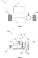
- FIG. 1 depicts one embodiment of an electric axle powertrain 1.
- the electric axle powertrain 1 includes an electric drivetrain 2 operably coupled to a differential 3.
- the differential 3 is a common differential gear set implemented to transmit rotational power.
- the differential 3 is operably coupled to a wheel drive axle 4 configured to drive a set of vehicle wheels 5 (labeled as "5A” and "5B" in FIG. 1 ).
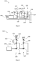
- FIG. 2 depicts one embodiment of an electric drivetrain 110 optionally used in the embodiments of electric axles disclosed herein.
- the drivetrain 110 includes a motor/generator 111 and a first planetary gear set 112 having a first ring gear 113, a first planet carrier 114, and a first sun gear 115.
- the drivetrain 110 includes a second planetary gear set 116 having a second ring gear 117, a second planet carrier 118, and a second sun gear 119.
- the motor/generator 111 is coupled to the first sun gear 115.
- the first planet carrier 114 is coupled to a first brake 120.
- the first ring gear 113 is operably coupled to the second ring gear 117.
- the second planet carrier 118 is coupled to a second brake 121.
- the second sun gear 119 is coupled to the first sun gear 115.
- rotational power is transmitted in and out of the drivetrain 110 through a node 122 coupled to the second ring gear 117.
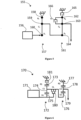
- FIG. 3 depicts one embodiment of an electric drivetrain 125 optionally used in the embodiments of electric axles disclosed herein.
- the drivetrain 125 includes a motor/generator 126 and a first planetary gear set 127 having a first ring gear 128, a first planet carrier 129, and a first sun gear 130.
- the drivetrain 125 includes a second planetary gear set 131 having a second ring gear 132, a second planet carrier 133, and a second sun gear 134.
- the drivetrain 125 includes a third planetary gear set 135 having a third ring gear 136, a third planet carrier 137, and a third sun gear 138.
- the motor/generator 126 is coupled to the first sun gear 130.
- the first planet carrier 129 is a grounded member.
- the first ring gear 128 is coupled to the second sun gear 134.
- the second planet carrier 133 is coupled to a first brake 139.
- the second sun gear 134 is coupled to the third sun gear 138.
- the third planet carrier 137 is coupled to a second brake 140.
- the second ring gear 132 is coupled to the third ring gear 136.
- a rotational power is transmitted in and out of the drivetrain 125 through the third ring gear 136.
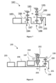
- FIG. 4 depicts one embodiment of an electric drivetrain 141 optionally used in the embodiments of electric axles disclosed herein.
- the drivetrain 141 includes a motor/generator 142 and a first planetary gear set 143 having a first ring gear 144, a first planet carrier 145, and a first sun gear 146.
- the drivetrain 141 includes a second planetary gear set 147 having a second ring gear 148, a second planet carrier 149, and a second sun gear 150.
- the motor/generator 142 is coupled to the first sun gear 146.
- the first planet carrier 145 is coupled to the second sun gear 150.
- the first planet carrier 145 is operably coupled to the first ring gear 144 through a clutch 152.
- the first ring gear 144 is coupled to a brake 151.
- the second ring gear 148 is a grounded member.
- a rotational power is transmitted in and out of the drivetrain 141 through the second planet carrier 149.
- FIG. 5 depicts one embodiment of an electric drivetrain 155 optionally used in the embodiments of electric axles disclosed herein.
- the drivetrain 155 includes a motor/generator 156 and a first planetary gear set 157 having a first ring gear 158, a first planet carrier 159, and a first sun gear 160.
- the drivetrain 155 includes a second planetary gear set 161 having a second ring gear 162, a second planet carrier 163, and a second sun gear 164.
- the motor/generator 156 is coupled to the first sun gear 160.
- the first planet carrier 159 is coupled to the second sun gear 164.
- the second planet carrier 163 is operably coupled to the second ring gear 162 through a clutch 166.
- the second ring gear 162 is coupled to a brake 165.
- the first ring gear 158 is a grounded member.
- a rotational power is transmitted in and out of the drivetrain 155 through the second planet carrier 163.
- FIG. 6 depicts one embodiment of an electric drivetrain 170 optionally used in the embodiments of electric axles disclosed herein.
- the drivetrain 170 includes a motor/generator 171 and a first planetary gear set 172 having a first ring gear 173, a first planet carrier 174, and a first sun gear 175.
- the drivetrain 170 includes a second planetary gear set 176 having a second ring gear 177, a second planet carrier 178, and a second sun gear 179.
- the motor/generator 171 is coupled to the first sun gear 175.
- the first planet carrier 174 is coupled to the second sun gear 179.
- the first sun gear 175 is coupled to the second sun gear 179 through a clutch 180.
- the first ring gear 173 is coupled to a brake 181.
- the second ring gear 177 is a grounded member.
- a rotational power is transmitted in and out of the drivetrain 170 through the second planet carrier 178.
- FIG. 7 depicts one embodiment of an electric drivetrain 182 optionally used in the embodiments of electric axles disclosed herein.
- the drivetrain 182 includes a motor/generator 183 and a first planetary gear set 184 having a first ring gear 185, a first planet carrier 186, and a first sun gear 187.
- the drivetrain 182 includes a second planetary gear set 188 having a second ring gear 189, a second planet carrier 190, and a second sun gear 191.
- the motor/generator 183 is coupled to the first sun gear 187.
- the first planet carrier 186 is coupled to the second sun gear 191.
- the second ring gear 189 is coupled to a brake 192.
- the first ring gear 185 is a grounded member.
- the second planet carrier 190 is operably coupled to the second sun gear 191 through a clutch 193.
- a rotational power is transmitted in and out of the drivetrain 182 through the second planet carrier 190.
- FIG. 8 depicts one embodiment of an electric 195 optionally used in the embodiments of electric axles disclosed herein.
- the drivetrain 195 includes a first motor/generator 196, a second motor/generator 197, and a planetary gear set 198 having a ring gear 199, a planet carrier 200, and a sun gear 201.
- the drivetrain 195 includes a brake 202, a first clutch 203, and a second clutch 204.
- the drivetrain 195 includes a one way clutch 205 coupled to the first motor/generator 196.
- the first clutch 203 is coupled to the first motor/generator 196 and the second motor/generator 197.
- the sun gear 201 is coupled to the first motor/generator 196.
- the second clutch 204 is coupled to the brake 202, the second motor/generator 197, and the ring gear 199.
- the planet carrier 200 is coupled to the sun gear 201. In some embodiments, a rotational power is transmitted in and out of the drivetrain 195 through the planet carrier 200.
- the drivetrain 195 is optionally operated in multiple modes.
- FIG. 9 does not depict an embodiment of the claimed invention.
- a low mode of operation corresponds to an engaged condition of the brake 202 and the first clutch 203 and the first and second motor/generators 196, 197 having a positive power output.
- a shift mode of operation corresponds to an engaged condition of the brake 202 and the first clutch 203 while reducing the second motor/generator output 197.
- a mode of operation having the second motor/generator 207 power output corresponds to an engaged condition of the brake 202 while the first clutch 203 disengages and the second clutch 204 disengages.
- a mode of operation having the second motor/generator 197 engaged while reducing the first motor/generator 196 corresponds to an engaged condition of the second clutch 204 while the brake 202 and the first clutch 203 are disengaged.
- a high mode of operation corresponds to the one-way clutch 205 engaged along with the second clutch 204 while the brake 202 and the first clutch 203 are disengaged.
- a high speed and torque mode of operation corresponds to an engaged second clutch 204 while the brake 202 and the first clutch 204 are disengaged and the first and second motor/generators 196, 197 have positive power output.
- a reverse mode of operation corresponds to an engaged second clutch 204 while the brake 202 and the first clutch 203 are disengaged and the second motor/generator 197 has positive power output and the first motor/generator 196 in regeneration.
- FIG. 10 depicts one embodiment of an electric drivetrain 206 optionally used in the embodiments of electric axles disclosed herein.
- the drivetrain 206 includes a first motor/generator 207, and a first planetary gear set 208, a second planetary gear set 209 and a third planetary gear set 210.
- the first planetary gear set 208 has a ring gear 211, a planet carrier 212, and a sun gear 213.
- the second planetary gear set 209 has a ring gear 214, a planet carrier 215, and a sun gear 216.
- the third planetary gear set 210 has a ring gear 217, a planet carrier 218, and a sun gear 219.
- the drivetrain 206 includes a brake 220, a first clutch 221, and a second clutch 222.
- the first clutch 221 is coupled to the ring gear 211 of the first planetary gear set and grounded.
- the second clutch 222 is coupled to the ring gear 217 of the third planetary gear set and grounded.
- the sun gear 213 is coupled to the first motor/generator 206.
- the planet carrier 212 of the first planetary gear set is connected to the sun gear 216 of the second planetary gear set.
- the ring gear 214 of the second planetary gear set is connected to the ring gear 217 of the third planetary gear set.
- the sun gear 219 of the third planetary gear set is connected to the sun gear 216 of the second planetary gear set.
- the planet carrier 215 of the second planetary gear set is coupled to the brake 220.
- a rotational power is transmitted in and out of the drivetrain 206 through the planet carrier 218 of the third planetary gear set.
- the drivetrain 205 is optionally operated in multiple modes. For example, a first mode of operation corresponds to an engaged condition of the brake 220 and the first clutch 221 and disengaged second clutch 222. A second mode of operation corresponds to an engaged condition of the second clutch 222 and the first clutch 221 and the brake disengaged. A neutral mode of operation corresponds to the brake 220 and the first clutch 221 being disengaged.
- FIG. 11 depicts one embodiment of an electric drivetrain 223 optionally used in the embodiments of electric axles disclosed herein.
- the drivetrain 223 includes a first motor/generator 224, and a first planetary gear set 225, a second planetary gear set 226 and a third planetary gear set 227.
- the first planetary gear set 225 has a ring gear 228, a planet carrier 229, and a sun gear 230.
- the second planetary gear set 226 has a ring gear 231, a planet carrier 232, and a sun gear 233.
- the third planetary gear set 210 has a ring gear 234, a planet carrier 235 and a sun gear 236.
- the drivetrain 223 includes a first clutch 237, a second clutch 238 and a third clutch 239.
- the first clutch 237 is coupled to the ring gear 228 of the first planetary gear set and grounded.
- the second clutch 238 is coupled to the ring gear 234 of the third planetary.
- the sun gear 230 is coupled to the first motor/generator 224.
- the planet carrier 229 of the first planetary gear set is connected to the sun gear 233 of the second planetary gear set.
- the ring gear 231 of the second planetary gear set is connected to the ring gear 229 of the first planetary gear set.
- the sun gear 234 of the third planetary gear set is connected to the sun gear 223 of the second planetary gear set.
- the planet carrier 232 of the second planetary gear set is coupled to the planet carrier 235 of the third planetary gear set.
- the third clutch 239 is coupled to the planet carrier 235 of the third planetary gear set.
- a rotational power is transmitted in and out of the drivetrain 223 through the planet carrier 235 and the ring gear 234 of the third planetary gear set.
- the drivetrain 223 is optionally operated in multiple modes.
- a first mode of operation corresponds to an engaged condition of the first clutch 237 and the second clutch 238 and the third clutch 239 disengaged.
- a second mode of operation corresponds to an engaged condition of the third clutch 239 and the first clutch 237 and the second clutch 238 disengaged.
- a neutral mode of operation corresponds to the first clutch 237, the second clutch 238 and the third clutch 239 being disengaged.
- the battery is capable of being not just a high voltage pack such as lithium ion or lead-acid batteries, but also ultracapacitors or other pneumatic/hydraulic systems such as accumulators, or other forms of energy storage systems.
- the motor/generators described herein are capable of representing hydromotors actuated by variable displacement pumps, electric machines, or any other form of rotary power such as pneumatic motors driven by pneumatic pumps.
- the electric axle powertrain architectures depicted in the figures and described in text is capable of being extended to create a hydro-mechanical architecture as well for hydraulic hybrid systems.
Landscapes
- Engineering & Computer Science (AREA)
- Mechanical Engineering (AREA)
- Chemical & Material Sciences (AREA)
- Combustion & Propulsion (AREA)
- Transportation (AREA)
- General Engineering & Computer Science (AREA)
- Electric Propulsion And Braking For Vehicles (AREA)
- Hybrid Electric Vehicles (AREA)
- Structure Of Transmissions (AREA)
- Arrangement Of Transmissions (AREA)
- Arrangement Or Mounting Of Propulsion Units For Vehicles (AREA)
Description
- The present application claims the benefit of
U.S. Provisional Application No. 62/428,127 filed on November 30, 2016 U.S. Provisional Application No. 62/434,015 filed on December 14, 2016 U.S. Provisional Application No. 62/452,714 filed on January 31, 2017 - The present invention relates to an axle powertrain.
- Hybrid vehicles are enjoying increased popularity and acceptance due in large part to the cost of fuel and greenhouse carbon emission government regulations for internal combustion engine vehicles. Such hybrid vehicles include both an internal combustion engine as well as an electric motor to propel the vehicle.
- In current electric axle designs for both consuming as well as storing electrical energy, the rotary shaft from a combination electric motor/generator is coupled by a gear train, planetary gear set, to the wheel. As such, the rotary shaft for the electric motor/generator unit rotates in unison with the wheel based on the speed ratio of the gear train.
- These fixed ratio designs have many disadvantages, for example, the electric motor/generator unit achieves its most efficient operation, both in the sense of generating electricity and also providing additional power to the wheel or the main shaft of the internal combustion engine, only within a relatively narrow range of revolutions per minute of the motor/generator unit. As such, the overall electric or hybrid electric vehicle operates at less than optimal efficiency over a drive cycle. Therefore, there is a need for powertrain configurations that improve the efficiency of electric and hybrid electric vehicles.
-
US 2015/158382 A1 discusses a two-speed transmission for a vehicle including a planetary gear set selectively coupling an input shaft and an output shaft. The planetary gear set is configured to provide two forward gear ratios and neutral. The planetary gear set includes at least one sun gear, at least one pinion in meshing engagement with the sun gear, at least one ring gear meshingly engaged with the pinion, and a carrier. The carrier supports the pinion and is connected to the output shaft such that rotation of the carrier drives the output shaft. The two-speed transmission also includes one or more elements that rotatably couple different combinations of the sun gear, the pinion, the ring gear, the input shaft, and the carrier with one another or a ground. Such elements may include combinations of clutches, brakes, band brakes, dog clutches, and mechanical diodes. -
JP 2006 335109 -
US 2015/167794 A1 discusses a drive apparatus for a hybrid vehicle which includes: an engine applying a drive force to drive wheels via a drive shaft; a motor applying a drive force to the drive wheels via a rotation shaft; a planetary gear mechanism having first, second, and third elements lining up sequentially with a gap interposed therebetween corresponding to a gear ratio; and an automatic transmission having input and output shafts rotatably connected to the drive wheels, and changing a gear ratio obtained by the division of the rotation speed of the input shaft by the rotation speed of the output shaft, wherein the input and drive shafts are connected to the second element, the output shaft and one end of the rotation shaft are connected to the first element, and the output shaft and the other end of the rotation shaft are connected to the third element. -
US 9 376 007 B2 -
US 2006/081722 A1 discusses low-content, low-cost electrically variable transmission mechanisms including first, second and third differential gear sets, a battery, two electric machines serving interchangeably as motors or generators and four selectable torque-transfer devices. The selectable torque transmitting devices are engaged to yield an EVT with a continuously variable range of speeds (including reverse) and four mechanically fixed forward speed ratios. The torque transmitting devices and the first and second motor/generators are operable to provide five operating modes in the electrically variable transmission, including battery reverse mode, EVT reverse mode, reverse and forward launch modes, continuously variable transmission range mode, and fixed ratio mode. - Provided herein is an electric axle powertrain including: an electric drivetrain including a motor/generator, a first planetary gear set operably coupled to the motor/generator, and a second planetary gear set operably coupled to the first planetary gear set, wherein the first planetary gear set includes a first ring gear, a first planet carrier, and a first sun gear and wherein the second planetary gear set includes a second ring gear, a second planet carrier, and a second sun gear; a drive wheel axle operably coupled to the electric drivetrain; and a first wheel and a second wheel coupled to the drive wheel axle.
- Provided herein is an electric axle powertrain including: an electric drivetrain including a first motor/generator, a second/motor generator, a planetary gear set operably coupled to the second motor/generator, wherein the planetary gear set includes a first ring gear, a first planet carrier, and a first sun gear; a drive wheel axle operably coupled to the electric drivetrain; and a first wheel and a second wheel coupled to the drive wheel axle.
- The invention is set out in the appended set of claims.
- Novel features of the preferred embodiments are set forth with particularity in the appended claims. A better understanding of the features and advantages of the preferred embodiments will be obtained by reference to the following detailed description that sets forth illustrative embodiments, in which the principles of the invention are utilized, and the accompanying drawings of which:
-
Figure 1 is a schematic diagram of an electric axle powertrain having an electric drivetrain drivingly engaged to a differential, axle, and wheels of a vehicle. -
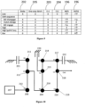
Figure 2 is a schematic diagram of an electric drivetrain having a motor/generator, two planetary gear sets, and two brakes.Figures 3 - 11 do not depict embodiments of the present invention. -
Figure 3 is a schematic diagram of an electric drivetrain having a motor/generator, three planetary gear sets, and two brakes. -
Figure 4 is a schematic diagram of an electric drivetrain having a motor/generator, two planetary gear sets, a clutch, and a brake. -
Figure 5 is a schematic diagram of another electric drivetrain having a motor/generator, two planetary gear sets, a clutch, and a brake. -
Figure 6 is a schematic diagram of an electric drivetrain having a motor/generator, two planetary gear sets, a clutch, and a brake. -
Figure 7 is a schematic diagram of another electric drivetrain having a motor/generator, two planetary gear sets, and a clutch. -
Figure 8 is a schematic diagram of an electric drivetrain having two motor/generators, a planetary gear set, two clutches, a one-way clutch, and a brake. -
Figure 9 is a table depicting operating modes of the drivetrain ofFigure 8 . -
Figure 10 is a schematic diagram of an electric drivetrain having a motor/generator, three planetary gear sets, two clutches and a brake. -
Figure 11 is a schematic diagram of an electric drivetrain having a motor/generator, three planetary gear sets, three clutches, and a brake. - The preferred embodiments will now be described with reference to the accompanying figures, wherein like numerals refer to like elements throughout. The terminology used in the descriptions below is not to be interpreted in any limited or restrictive manner simply because it is used in conjunction with detailed descriptions of certain specific embodiments. Furthermore, the embodiments include several novel features, no single one of which is solely responsible for its desirable attributes or which is essential to practicing the embodiments described.
- This powertrain relates to electric powertrain configurations and architectures that will be used in hybrid vehicles. The powertrain and/or drivetrain configurations use a transmission in order to couple power sources used in a hybrid vehicle, for example, combustion engines (internal or external), motors, generators, batteries, and gearing. The powertrains disclosed herein are applicable to HEV, EV and Fuel Cell Hybrid systems. Embodiments disclosed herein are directed to hybrid vehicle architectures and/or configurations for use in electric axle or hybrid electrical vehicle drivetrain. It should be appreciated that the embodiments disclosed herein are adapted to provide hybrid modes of operation that include, but are not limited to series, parallel, series-parallel, or EV (electric vehicle) modes.
- It should be noted that hydro-mechanical components such as hydromotors, pumps, accumulators, among others, are capable of being used in place of the electric machines indicated in the figures and accompanying textual description. Furthermore, it should be noted that embodiments of E-axle architectures disclosed herein could incorporate a supervisory controller that chooses the highest efficiency and/or power from motor/generator to wheel.
- It should be understood that electric or hybrid electric vehicles incorporating embodiments of the hybrid architectures disclosed herein are capable of including a number of other powertrain components, such as, but not limited to, high-voltage battery pack with a battery management system or ultracapacitor, on-board charger, DC-DC converters, a variety of sensors, actuators, and controllers, among others.
- For purposes of description, schematics referred to as lever diagrams are used herein. A lever diagram, also known as a lever analogy diagram, is a translational-system representation of rotating parts for a planetary gear system. In certain embodiments, a lever diagram is provided as a visual aid in describing the functions of the transmission. In a lever diagram, a compound planetary gear set is often represented by a single vertical line ("lever"). The input, output, and reaction torques are represented by horizontal forces on the lever. The lever motion, relative to the reaction point, represents direction of rotational velocities. For example, a typical planetary gear set having a ring gear, a planet carrier, and a sun gear is represented by a vertical line having nodes "R" representing the ring gear, node "S" representing the sun gear, and node "C" representing the planet carrier. It should be appreciated that any mechanical coupling is depicted on a lever diagram as a node or a solid dot. For example, a node represents two components in a drivetrain that are rigidly connected.
- As used here, the terms "operationally connected," "operationally coupled", "operationally linked", "operably connected", "operably coupled", "operably linked," and like terms, refer to a relationship (mechanical, linkage, coupling, etc.) between elements whereby operation of one element results in a corresponding, following, or simultaneous operation or actuation of a second element. It is noted that in using said terms to describe the preferred embodiments, specific structures or mechanisms that link or couple the elements are typically described. However, unless otherwise specifically stated, when one of said terms is used, the term indicates that the actual linkage or coupling is capable of taking a variety of forms, which in certain instances will be readily apparent to a person of ordinary skill in the relevant technology.
-
FIG. 1 depicts one embodiment of anelectric axle powertrain 1. In some embodiments, theelectric axle powertrain 1 includes anelectric drivetrain 2 operably coupled to adifferential 3. In some embodiments, the differential 3 is a common differential gear set implemented to transmit rotational power. The differential 3 is operably coupled to awheel drive axle 4 configured to drive a set of vehicle wheels 5 (labeled as "5A" and "5B" inFIG. 1 ). -
FIG. 2 depicts one embodiment of anelectric drivetrain 110 optionally used in the embodiments of electric axles disclosed herein. Thedrivetrain 110 includes a motor/generator 111 and a first planetary gear set 112 having afirst ring gear 113, afirst planet carrier 114, and afirst sun gear 115. Thedrivetrain 110 includes a second planetary gear set 116 having asecond ring gear 117, asecond planet carrier 118, and asecond sun gear 119. In some embodiments, the motor/generator 111 is coupled to thefirst sun gear 115. Thefirst planet carrier 114 is coupled to afirst brake 120. Thefirst ring gear 113 is operably coupled to thesecond ring gear 117. Thesecond planet carrier 118 is coupled to asecond brake 121. Thesecond sun gear 119 is coupled to thefirst sun gear 115. In some embodiments, rotational power is transmitted in and out of thedrivetrain 110 through anode 122 coupled to thesecond ring gear 117. -
FIG. 3 depicts one embodiment of anelectric drivetrain 125 optionally used in the embodiments of electric axles disclosed herein.FIG. 3 does not depict an embodiment of the claimed invention. Thedrivetrain 125 includes a motor/generator 126 and a first planetary gear set 127 having afirst ring gear 128, afirst planet carrier 129, and afirst sun gear 130. Thedrivetrain 125 includes a second planetary gear set 131 having a second ring gear 132, asecond planet carrier 133, and asecond sun gear 134. Thedrivetrain 125 includes a third planetary gear set 135 having athird ring gear 136, athird planet carrier 137, and athird sun gear 138. In some embodiments, the motor/generator 126 is coupled to thefirst sun gear 130. Thefirst planet carrier 129 is a grounded member. Thefirst ring gear 128 is coupled to thesecond sun gear 134. Thesecond planet carrier 133 is coupled to a first brake 139. Thesecond sun gear 134 is coupled to thethird sun gear 138. Thethird planet carrier 137 is coupled to asecond brake 140. The second ring gear 132 is coupled to thethird ring gear 136. In some embodiments, a rotational power is transmitted in and out of thedrivetrain 125 through thethird ring gear 136. -
FIG. 4 depicts one embodiment of anelectric drivetrain 141 optionally used in the embodiments of electric axles disclosed herein.FIG. 4 does not depict an embodiment of the claimed invention. Thedrivetrain 141 includes a motor/generator 142 and a first planetary gear set 143 having afirst ring gear 144, afirst planet carrier 145, and afirst sun gear 146. Thedrivetrain 141 includes a second planetary gear set 147 having asecond ring gear 148, asecond planet carrier 149, and asecond sun gear 150. In some embodiments, the motor/generator 142 is coupled to thefirst sun gear 146. Thefirst planet carrier 145 is coupled to thesecond sun gear 150. In some embodiments, thefirst planet carrier 145 is operably coupled to thefirst ring gear 144 through a clutch 152. Thefirst ring gear 144 is coupled to abrake 151. Thesecond ring gear 148 is a grounded member. In some embodiments, a rotational power is transmitted in and out of thedrivetrain 141 through thesecond planet carrier 149. -
FIG. 5 depicts one embodiment of anelectric drivetrain 155 optionally used in the embodiments of electric axles disclosed herein.FIG. 5 does not depict an embodiment of the claimed invention. Thedrivetrain 155 includes a motor/generator 156 and a first planetary gear set 157 having afirst ring gear 158, afirst planet carrier 159, and a first sun gear 160. Thedrivetrain 155 includes a second planetary gear set 161 having asecond ring gear 162, asecond planet carrier 163, and asecond sun gear 164. In some embodiments, the motor/generator 156 is coupled to the first sun gear 160. Thefirst planet carrier 159 is coupled to thesecond sun gear 164. In some embodiments, thesecond planet carrier 163 is operably coupled to thesecond ring gear 162 through a clutch 166. Thesecond ring gear 162 is coupled to abrake 165. Thefirst ring gear 158 is a grounded member. In some embodiments, a rotational power is transmitted in and out of thedrivetrain 155 through thesecond planet carrier 163. -
FIG. 6 depicts one embodiment of anelectric drivetrain 170 optionally used in the embodiments of electric axles disclosed herein.FIG. 6 does not depict an embodiment of the claimed invention. Thedrivetrain 170 includes a motor/generator 171 and a first planetary gear set 172 having afirst ring gear 173, afirst planet carrier 174, and afirst sun gear 175. Thedrivetrain 170 includes a second planetary gear set 176 having asecond ring gear 177, asecond planet carrier 178, and asecond sun gear 179. In some embodiments, the motor/generator 171 is coupled to thefirst sun gear 175. Thefirst planet carrier 174 is coupled to thesecond sun gear 179. In some embodiments, thefirst sun gear 175 is coupled to thesecond sun gear 179 through a clutch 180. In some embodiments, thefirst ring gear 173 is coupled to abrake 181. Thesecond ring gear 177 is a grounded member. In some embodiments, a rotational power is transmitted in and out of thedrivetrain 170 through thesecond planet carrier 178. -
FIG. 7 depicts one embodiment of anelectric drivetrain 182 optionally used in the embodiments of electric axles disclosed herein.FIG. 7 does not depict an embodiment of the claimed invention. Thedrivetrain 182 includes a motor/generator 183 and a first planetary gear set 184 having afirst ring gear 185, afirst planet carrier 186, and afirst sun gear 187. Thedrivetrain 182 includes a second planetary gear set 188 having asecond ring gear 189, asecond planet carrier 190, and asecond sun gear 191. In some embodiments, the motor/generator 183 is coupled to thefirst sun gear 187. Thefirst planet carrier 186 is coupled to thesecond sun gear 191. In some embodiments, thesecond ring gear 189 is coupled to a brake 192. Thefirst ring gear 185 is a grounded member. In some embodiments, thesecond planet carrier 190 is operably coupled to thesecond sun gear 191 through a clutch 193. In some embodiments, a rotational power is transmitted in and out of thedrivetrain 182 through thesecond planet carrier 190. -
FIG. 8 depicts one embodiment of an electric 195 optionally used in the embodiments of electric axles disclosed herein.FIG. 8 does not depict an embodiment of the claimed invention. Thedrivetrain 195 includes a first motor/generator 196, a second motor/generator 197, and a planetary gear set 198 having aring gear 199, aplanet carrier 200, and asun gear 201. In some embodiments, thedrivetrain 195 includes abrake 202, afirst clutch 203, and asecond clutch 204. In some embodiments, thedrivetrain 195 includes a one way clutch 205 coupled to the first motor/generator 196. Thefirst clutch 203 is coupled to the first motor/generator 196 and the second motor/generator 197. Thesun gear 201 is coupled to the first motor/generator 196. Thesecond clutch 204 is coupled to thebrake 202, the second motor/generator 197, and thering gear 199. Theplanet carrier 200 is coupled to thesun gear 201. In some embodiments, a rotational power is transmitted in and out of thedrivetrain 195 through theplanet carrier 200. - Turning now to
FIG. 9 , in some embodiments, thedrivetrain 195 is optionally operated in multiple modes.FIG. 9 does not depict an embodiment of the claimed invention. For example, a low mode of operation corresponds to an engaged condition of thebrake 202 and thefirst clutch 203 and the first and second motor/generators brake 202 and thefirst clutch 203 while reducing the second motor/generator output 197. A mode of operation having the second motor/generator 207 power output corresponds to an engaged condition of thebrake 202 while thefirst clutch 203 disengages and thesecond clutch 204 disengages. A mode of operation having the second motor/generator 197 engaged while reducing the first motor/generator 196 corresponds to an engaged condition of thesecond clutch 204 while thebrake 202 and thefirst clutch 203 are disengaged. A high mode of operation corresponds to the one-way clutch 205 engaged along with thesecond clutch 204 while thebrake 202 and thefirst clutch 203 are disengaged. A high speed and torque mode of operation corresponds to an engaged second clutch 204 while thebrake 202 and thefirst clutch 204 are disengaged and the first and second motor/generators brake 202 and thefirst clutch 203 are disengaged and the second motor/generator 197 has positive power output and the first motor/generator 196 in regeneration. -
FIG. 10 depicts one embodiment of an electric drivetrain 206 optionally used in the embodiments of electric axles disclosed herein.FIG. 10 does not depict an embodiment of the claimed invention. The drivetrain 206 includes a first motor/generator 207, and a first planetary gear set 208, a second planetary gear set 209 and a third planetary gear set 210. The first planetary gear set 208 has aring gear 211, aplanet carrier 212, and asun gear 213. The second planetary gear set 209 has aring gear 214, aplanet carrier 215, and asun gear 216. The third planetary gear set 210 has aring gear 217, aplanet carrier 218, and asun gear 219. In some embodiments, the drivetrain 206 includes abrake 220, afirst clutch 221, and asecond clutch 222. In some embodiments, thefirst clutch 221 is coupled to thering gear 211 of the first planetary gear set and grounded. Thesecond clutch 222 is coupled to thering gear 217 of the third planetary gear set and grounded. Thesun gear 213 is coupled to the first motor/generator 206. Theplanet carrier 212 of the first planetary gear set is connected to thesun gear 216 of the second planetary gear set. Thering gear 214 of the second planetary gear set is connected to thering gear 217 of the third planetary gear set. Thesun gear 219 of the third planetary gear set is connected to thesun gear 216 of the second planetary gear set. Theplanet carrier 215 of the second planetary gear set is coupled to thebrake 220. In some embodiments, a rotational power is transmitted in and out of the drivetrain 206 through theplanet carrier 218 of the third planetary gear set. - The
drivetrain 205 is optionally operated in multiple modes. For example, a first mode of operation corresponds to an engaged condition of thebrake 220 and thefirst clutch 221 and disengagedsecond clutch 222. A second mode of operation corresponds to an engaged condition of thesecond clutch 222 and thefirst clutch 221 and the brake disengaged. A neutral mode of operation corresponds to thebrake 220 and thefirst clutch 221 being disengaged. -
FIG. 11 depicts one embodiment of an electric drivetrain 223 optionally used in the embodiments of electric axles disclosed herein.FIG. 11 does not depict an embodiment of the claimed invention. The drivetrain 223 includes a first motor/generator 224, and a first planetary gear set 225, a second planetary gear set 226 and a third planetary gear set 227. The first planetary gear set 225 has aring gear 228, aplanet carrier 229, and asun gear 230. The second planetary gear set 226 has aring gear 231, aplanet carrier 232, and asun gear 233. The third planetary gear set 210 has aring gear 234, aplanet carrier 235 and asun gear 236. In some embodiments, the drivetrain 223 includes afirst clutch 237, asecond clutch 238 and athird clutch 239. In some embodiments, thefirst clutch 237 is coupled to thering gear 228 of the first planetary gear set and grounded. Thesecond clutch 238 is coupled to thering gear 234 of the third planetary. Thesun gear 230 is coupled to the first motor/generator 224. Theplanet carrier 229 of the first planetary gear set is connected to thesun gear 233 of the second planetary gear set. Thering gear 231 of the second planetary gear set is connected to thering gear 229 of the first planetary gear set. Thesun gear 234 of the third planetary gear set is connected to the sun gear 223 of the second planetary gear set. Theplanet carrier 232 of the second planetary gear set is coupled to theplanet carrier 235 of the third planetary gear set. Thethird clutch 239 is coupled to theplanet carrier 235 of the third planetary gear set. In some embodiments, a rotational power is transmitted in and out of the drivetrain 223 through theplanet carrier 235 and thering gear 234 of the third planetary gear set. - The drivetrain 223 is optionally operated in multiple modes. For example, a first mode of operation corresponds to an engaged condition of the
first clutch 237 and thesecond clutch 238 and the third clutch 239 disengaged. A second mode of operation corresponds to an engaged condition of thethird clutch 239 and thefirst clutch 237 and thesecond clutch 238 disengaged. A neutral mode of operation corresponds to thefirst clutch 237, thesecond clutch 238 and the third clutch 239 being disengaged. This embodiment is not an embodiment of the invention but helpful to understand certain aspects thereof. - It should be noted that the battery is capable of being not just a high voltage pack such as lithium ion or lead-acid batteries, but also ultracapacitors or other pneumatic/hydraulic systems such as accumulators, or other forms of energy storage systems. The motor/generators described herein are capable of representing hydromotors actuated by variable displacement pumps, electric machines, or any other form of rotary power such as pneumatic motors driven by pneumatic pumps. The electric axle powertrain architectures depicted in the figures and described in text is capable of being extended to create a hydro-mechanical architecture as well for hydraulic hybrid systems.
- It should be noted that the description above has provided dimensions for certain components or subassemblies. The mentioned dimensions, or ranges of dimensions, are provided in order to comply as best as possible with certain legal requirements, such as best mode. However, the scope of the inventions described herein are to be determined solely by the language of the claims, and consequently, none of the mentioned dimensions are to be considered limiting on the preferred embodiments, except in so far as any one claim makes a specified dimension, or range of thereof, a feature of the claim.
- While the preferred embodiments have been shown and described herein, it will be obvious to those skilled in the art that such embodiments are provided by way of example only. Numerous variations, changes, and substitutions will now occur to those skilled in the art without departing from the invention. It should be understood that various alternatives to the embodiments described herein are capable of being employed in practicing the preferred embodiments. It is intended that the following claims define the scope of the invention and that methods and structures within the scope of these claims and their equivalents be covered thereby.
Claims (1)
- An axle powertrain comprising:
an electric drivetrain (110) comprisinga motor/generator (111),a first planetary gear set (112) operably coupled to the
motor/generator (111), anda second planetary gear set (116) operably coupled to the first planetary gear set (112),wherein the first planetary gear set (112) comprises a first ring gear (113), a first planet carrier (114), and a first sun gear (115), and wherein the second planetary gear set (116) comprises a second ring gear (117), a second planet carrier (118), and a second sun gear (119);a drive wheel axle operably coupled to the electric drivetrain (110); anda first wheel and a second wheel coupled to the drive wheel axle,wherein the motor/generator (111) is coupled to the first sun gear (115), andwherein the first sun gear (115) is coupled to the second sun gear (119),
characterised bya first brake (120) coupled to the first planet carrier (114), and a second brake (121) coupled to the second planet carrier (118), wherein the first ring gear (113) is coupled to the second ring gear (117).
Applications Claiming Priority (4)
| Application Number | Priority Date | Filing Date | Title |
|---|---|---|---|
| US201662428127P | 2016-11-30 | 2016-11-30 | |
| US201662434015P | 2016-12-14 | 2016-12-14 | |
| US201762452714P | 2017-01-31 | 2017-01-31 | |
| PCT/US2017/063852 WO2018102498A1 (en) | 2016-11-30 | 2017-11-30 | Electric axle transmission for electric and hybrid electric vehicles |
Publications (3)
| Publication Number | Publication Date |
|---|---|
| EP3548322A1 EP3548322A1 (en) | 2019-10-09 |
| EP3548322A4 EP3548322A4 (en) | 2020-11-11 |
| EP3548322B1 true EP3548322B1 (en) | 2023-06-14 |
Family
ID=62241874
Family Applications (1)
| Application Number | Title | Priority Date | Filing Date |
|---|---|---|---|
| EP17876607.7A Active EP3548322B1 (en) | 2016-11-30 | 2017-11-30 | Electric axle transmission for electric and hybrid electric vehicles |
Country Status (7)
| Country | Link |
|---|---|
| US (1) | US11365785B2 (en) |
| EP (1) | EP3548322B1 (en) |
| JP (1) | JP2020500764A (en) |
| KR (1) | KR20190060839A (en) |
| CN (1) | CN109996695B (en) |
| BR (1) | BR112019010537A2 (en) |
| WO (1) | WO2018102498A1 (en) |
Families Citing this family (32)
| Publication number | Priority date | Publication date | Assignee | Title |
|---|---|---|---|---|
| DE102017223158A1 (en) * | 2017-12-19 | 2019-06-19 | Zf Friedrichshafen Ag | Electric drive arrangement for working machine |
| WO2019241773A1 (en) * | 2018-06-15 | 2019-12-19 | Dana Automotive Systems Group, Llc | Multi-speed gearbox with high torque ratio and the drive axle made therewith |
| CN112654803A (en) | 2018-10-22 | 2021-04-13 | 加特可株式会社 | Supporting structure of gear |
| JP7057836B2 (en) * | 2018-10-22 | 2022-04-20 | ジヤトコ株式会社 | Forward / backward switching mechanism |
| JP7052685B2 (en) | 2018-11-15 | 2022-04-12 | トヨタ自動車株式会社 | Vehicle gear train |
| CN113454364A (en) * | 2019-02-08 | 2021-09-28 | 加特可株式会社 | Power transmission device |
| JP7238587B2 (en) * | 2019-05-10 | 2023-03-14 | 株式会社豊田中央研究所 | vehicle drive |
| DE102019119950B3 (en) * | 2019-07-24 | 2020-10-29 | Schaeffler Technologies AG & Co. KG | Drive device for a motor vehicle with the same sun gears |
| US11486478B2 (en) | 2019-07-29 | 2022-11-01 | Dana Heavy Vehicle Systems Group, Llc | Multi-speed electric transmission assembly and axle assembly |
| DE102019214986A1 (en) | 2019-09-30 | 2021-04-01 | Zf Friedrichshafen Ag | Drive axle of an electric vehicle and powershift process |
| WO2021078372A1 (en) | 2019-10-23 | 2021-04-29 | Volvo Construction Equipment Ab | A transmission assembly |
| DE102019216562A1 (en) * | 2019-10-28 | 2021-04-29 | Zf Friedrichshafen Ag | Drive arrangement of an electric vehicle and load shifting method |
| WO2022102537A1 (en) | 2020-11-11 | 2022-05-19 | 株式会社クボタ | Power transmission mechanism and work vehicle |
| JP2022096414A (en) * | 2020-12-17 | 2022-06-29 | トヨタ自動車株式会社 | Transaxle for electric vehicle |
| CN112895883B (en) * | 2021-02-19 | 2022-06-03 | 西安交通大学 | Dual-drive-source and double-row planetary gear train multi-mode coupling driving system and automobile |
| CN113071306A (en) * | 2021-04-26 | 2021-07-06 | 合肥工业大学 | Multi-gear rotatable hub power assembly |
| DE102021002327A1 (en) | 2021-05-03 | 2022-11-03 | Daimler Truck AG | Motor vehicle, in particular commercial vehicle |
| KR102923051B1 (en) * | 2021-07-14 | 2026-02-04 | 현대자동차 주식회사 | Power transmission system for electric vehicle |
| DE102021005017A1 (en) | 2021-10-07 | 2023-04-13 | Mercedes-Benz Group AG | Electric drive device for a motor vehicle, in particular for a motor vehicle, and motor vehicle |
| DE102021211713A1 (en) * | 2021-10-18 | 2023-04-20 | Zf Friedrichshafen Ag | electric vehicle transmission |
| DE102021212164A1 (en) * | 2021-10-28 | 2023-05-04 | Zf Friedrichshafen Ag | electric vehicle transmission |
| DE102022201820A1 (en) * | 2022-02-22 | 2023-08-24 | Zf Friedrichshafen Ag | Transmission for an electric drive system of a motor vehicle and electric drive system with such a transmission |
| DE102022203097A1 (en) | 2022-03-30 | 2023-10-05 | Zf Friedrichshafen Ag | Drive unit for a drive axle of a vehicle |
| DE102022203098A1 (en) | 2022-03-30 | 2023-10-05 | Zf Friedrichshafen Ag | Drive unit for a drive axle of a vehicle |
| CN114877038B (en) * | 2022-05-13 | 2025-05-06 | 东华大学 | A multi-mode electromechanical compound transmission for a vehicle |
| DE102022209050A1 (en) | 2022-08-31 | 2024-02-29 | Zf Friedrichshafen Ag | Method and control device for operating a drive train of a vehicle |
| DE102022209051A1 (en) | 2022-08-31 | 2024-02-29 | Zf Friedrichshafen Ag | Method and control device for operating a drive train of a vehicle |
| DE102022209060A1 (en) * | 2022-08-31 | 2024-02-29 | Zf Friedrichshafen Ag | Motor vehicle transmission for an at least partially electrically driven motor vehicle |
| US12337679B2 (en) * | 2023-03-16 | 2025-06-24 | Dana Belgium N.V. | Electric drive unit and method for drive unit operation |
| DE102023211832A1 (en) | 2023-11-28 | 2025-05-28 | Zf Friedrichshafen Ag | Electric vehicle transmission |
| DE102023212673A1 (en) | 2023-12-14 | 2025-06-18 | Zf Friedrichshafen Ag | Motor vehicle transmission for an at least partially electrically powered motor vehicle |
| US12454176B1 (en) * | 2024-04-25 | 2025-10-28 | Dana Italia S.R.L. | Systems for a dual motor powertrain |
Family Cites Families (107)
| Publication number | Priority date | Publication date | Assignee | Title |
|---|---|---|---|---|
| JPH11107798A (en) * | 1997-10-08 | 1999-04-20 | Aisin Aw Co Ltd | Hybrid drive |
| JP3649058B2 (en) * | 1999-10-08 | 2005-05-18 | トヨタ自動車株式会社 | Vehicle control apparatus having a plurality of prime movers |
| DE10049567B4 (en) * | 1999-10-08 | 2017-12-14 | Toyota Jidosha Kabushiki Kaisha | Vehicle control unit for controlling a four-wheel drive motor vehicle |
| JP3804383B2 (en) * | 2000-01-19 | 2006-08-02 | トヨタ自動車株式会社 | Control device for vehicle having fuel cell |
| DE10165097B3 (en) * | 2000-07-18 | 2015-07-23 | Schaeffler Technologies AG & Co. KG | Double clutch |
| US6579201B2 (en) * | 2000-08-22 | 2003-06-17 | New Venture Gear, Inc. | Electric hybrid four-wheel drive vehicle |
| JP3692916B2 (en) * | 2000-08-29 | 2005-09-07 | トヨタ自動車株式会社 | Power output device and automobile equipped with the same |
| US6490945B2 (en) * | 2001-01-10 | 2002-12-10 | New Venture Gear, Inc. | Twin clutch automated transmission with integrated transfer case |
| DE10209514B4 (en) * | 2001-03-30 | 2016-06-09 | Schaeffler Technologies AG & Co. KG | powertrain |
| US6575866B2 (en) * | 2001-04-09 | 2003-06-10 | New Venture Gear, Inc. | Hybrid drive system for motor vehicle with powershift transmission |
| DE10243535A1 (en) * | 2001-09-26 | 2003-04-24 | Luk Lamellen & Kupplungsbau | Hybrid drive device for motor vehicle such as tourism vehicle, has engine and electric motor that can be connected to drive connection by coupling so that motor is coupled with drive side of gearbox and/or with engine |
| JP3852321B2 (en) * | 2001-10-22 | 2006-11-29 | トヨタ自動車株式会社 | HV drive structure and method with cranking support torque increasing means |
| CN1301200C (en) * | 2002-09-13 | 2007-02-21 | 本田技研工业株式会社 | hybrid vehicle |
| JP3858898B2 (en) * | 2004-02-13 | 2006-12-20 | 日産自動車株式会社 | Mode change control device for hybrid transmission |
| JP4069901B2 (en) * | 2004-05-20 | 2008-04-02 | トヨタ自動車株式会社 | Hybrid vehicle drivetrain |
| JP2006144774A (en) | 2004-10-18 | 2006-06-08 | Denso Corp | Gaseous fuel injection injector |
| US7179186B2 (en) * | 2005-01-04 | 2007-02-20 | General Motors Corporation | Electrically variable transmission having three interconnected planetary gear sets |
| JP4244944B2 (en) * | 2005-03-16 | 2009-03-25 | トヨタ自動車株式会社 | Control device for vehicle drive device |
| JP4529798B2 (en) | 2005-05-31 | 2010-08-25 | 日産自動車株式会社 | Rotation information calculation device for transmission mechanism |
| JP2007001493A (en) * | 2005-06-27 | 2007-01-11 | Nissan Motor Co Ltd | Control unit for hybrid vehicle |
| US7575529B2 (en) * | 2006-09-13 | 2009-08-18 | Gm Global Technology Operations, Inc. | Hybrid electrically variable transmission with geared reverse mode using single motor/generator |
| US7648437B2 (en) * | 2006-09-28 | 2010-01-19 | Gm Global Technology Operations, Inc. | Multi-mode electrically variable transmissions with interconnected gearsets |
| US7479082B2 (en) * | 2006-11-17 | 2009-01-20 | Gm Global Technology Operations, Inc. | Hybrid powertrain having three interconnecting members and brakes |
| JP4100444B1 (en) * | 2006-12-18 | 2008-06-11 | トヨタ自動車株式会社 | Hybrid drive device |
| US7998014B2 (en) * | 2007-04-04 | 2011-08-16 | GM Global Technology Operations LLC | 8-speed transmission |
| DE102008049491B4 (en) * | 2007-10-11 | 2017-05-04 | GM Global Technology Operations LLC (n. d. Ges. d. Staates Delaware) | Multi-speed transmission |
| US10077823B2 (en) * | 2007-12-04 | 2018-09-18 | Xiaolin Ai | Multimode electromechanical variable speed transmission apparatus and method of control |
| US8622862B2 (en) * | 2009-03-24 | 2014-01-07 | Honda Motor Co., Ltd. | Power transmitting device |
| ITBO20090465A1 (en) * | 2009-07-21 | 2011-01-22 | Ferrari Spa | TRANSMISSION FOR A ROAD VEHICLE WITH HYBRID PROPULSION |
| CN102107604B (en) * | 2009-12-25 | 2013-12-18 | 比亚迪股份有限公司 | Hybrid driving system for automobile and gear operating method thereof |
| WO2011125222A1 (en) * | 2010-04-09 | 2011-10-13 | トヨタ自動車株式会社 | Vehicle driving force control device |
| JP5492990B2 (en) * | 2010-06-15 | 2014-05-14 | 本田技研工業株式会社 | Car drive system |
| US8337352B2 (en) * | 2010-06-22 | 2012-12-25 | Oshkosh Corporation | Electromechanical variable transmission |
| US8915822B2 (en) * | 2010-07-09 | 2014-12-23 | Honda Motor Co., Ltd. | Vehicle driving system and control method thereof |
| JP5108071B2 (en) * | 2010-09-22 | 2012-12-26 | 富士重工業株式会社 | Drive device for hybrid vehicle |
| KR101219932B1 (en) * | 2010-11-09 | 2013-01-08 | 기아자동차주식회사 | Method for Determining Operating State of Element of Transmission |
| CN103221242B (en) * | 2010-12-03 | 2015-12-02 | 本田技研工业株式会社 | hybrid drive |
| US9156344B2 (en) * | 2010-12-13 | 2015-10-13 | GM Global Technology Operations LLC | Motor-assisted transmission |
| US8827860B2 (en) | 2011-01-06 | 2014-09-09 | Gm Global Technology Operations, Llc | Torque transmitting device control strategy for a nine speed transmission |
| US8795113B2 (en) * | 2011-01-12 | 2014-08-05 | Gm Global Technology Operations, Llc | Hybrid powertrain for a motor vehicle |
| US8858376B2 (en) * | 2011-01-12 | 2014-10-14 | Gm Global Technology Operations, Llc | Hybrid powertrain for a motor vehicle |
| JP5644868B2 (en) * | 2011-01-27 | 2014-12-24 | トヨタ自動車株式会社 | Vehicle and vehicle control method |
| US8187130B1 (en) | 2011-02-17 | 2012-05-29 | GM Global Technology Operations LLC | Multi-speed transmission with integrated electric motor |
| KR101283046B1 (en) | 2011-06-20 | 2013-07-05 | 기아자동차주식회사 | Power transmission system of hybrid electric vehicle |
| US8597146B2 (en) * | 2011-08-30 | 2013-12-03 | GM Global Technology Operations LLC | Powertrain with two planetary gear sets, two motor/generators and multiple power-split operating modes |
| JP5455994B2 (en) * | 2011-08-31 | 2014-03-26 | 本田技研工業株式会社 | Car drive system |
| WO2013041142A1 (en) * | 2011-09-22 | 2013-03-28 | Schaeffler Technologies AG & Co. KG | Drive unit comprising an electric motor |
| JP5811187B2 (en) * | 2011-11-24 | 2015-11-11 | トヨタ自動車株式会社 | Shift instruction device for hybrid vehicle |
| KR20130067865A (en) * | 2011-12-14 | 2013-06-25 | 현대자동차주식회사 | Control method of hybrid vehicle |
| JP2013139225A (en) * | 2012-01-05 | 2013-07-18 | Toyota Motor Corp | Control apparatus |
| JP2013166409A (en) * | 2012-02-14 | 2013-08-29 | Toyota Motor Corp | Vehicular drive device |
| AT513538B1 (en) * | 2012-10-22 | 2015-01-15 | Avl List Gmbh | transmission |
| KR20140059917A (en) * | 2012-11-08 | 2014-05-19 | 현대자동차주식회사 | Double clutch powertrain for vehicle |
| JP5939309B2 (en) * | 2012-12-26 | 2016-06-22 | トヨタ自動車株式会社 | Control device for hybrid vehicle |
| CN104918813B (en) * | 2013-01-28 | 2017-09-26 | 丰田自动车株式会社 | Motor vehicle driven by mixed power |
| US8979694B2 (en) * | 2013-02-22 | 2015-03-17 | GM Global Technology Operations LLC | Hybrid vehicle with power-split and parallel hybrid transmission and method of controlling same |
| JP2014184804A (en) * | 2013-03-22 | 2014-10-02 | Toyota Motor Corp | Control unit of vehicular transmission system |
| JP5867440B2 (en) * | 2013-04-01 | 2016-02-24 | トヨタ自動車株式会社 | Vehicle control device |
| KR101550605B1 (en) * | 2013-11-22 | 2015-09-08 | 현대자동차 주식회사 | Power transmission system of hybrid electric vehicle |
| US20150158382A1 (en) * | 2013-12-05 | 2015-06-11 | Avl Powertrain Engineering, Inc. | Two-speed transmission for electric vehicle |
| JP2015113102A (en) * | 2013-12-16 | 2015-06-22 | アイシン精機株式会社 | Hybrid vehicle drive device |
| EP3100885B1 (en) * | 2014-01-30 | 2020-07-15 | BYD Company Limited | Vehicle and power transmission system thereof |
| US9568082B2 (en) * | 2014-01-30 | 2017-02-14 | Byd Company Limited | Power transmission system for vehicle and vehicle comprising the same |
| CN104276176B (en) * | 2014-01-30 | 2015-09-02 | 比亚迪股份有限公司 | The cruise control method of vehicle and vehicle |
| SE539662C2 (en) * | 2014-03-20 | 2017-10-24 | Scania Cv Ab | Method of starting an internal combustion engine in a hybrid drive line, vehicles with such a hybrid drive line, computer programs for starting an internal combustion engine, and a computer program product including program code |
| JP2016055759A (en) * | 2014-09-09 | 2016-04-21 | トヨタ自動車株式会社 | Control device for hybrid vehicle |
| JP6090273B2 (en) * | 2014-09-17 | 2017-03-08 | トヨタ自動車株式会社 | Hybrid car |
| KR101637692B1 (en) * | 2014-10-13 | 2016-07-07 | 현대자동차주식회사 | Transmission structure of HEV |
| CN104786815B (en) * | 2015-01-16 | 2016-03-30 | 比亚迪股份有限公司 | Transmissions, Drivelines and Vehicles |
| US10982736B2 (en) * | 2015-02-17 | 2021-04-20 | Oshkosh Corporation | Multi-mode electromechanical variable transmission |
| US9651120B2 (en) * | 2015-02-17 | 2017-05-16 | Oshkosh Corporation | Multi-mode electromechanical variable transmission |
| US10421350B2 (en) * | 2015-10-20 | 2019-09-24 | Oshkosh Corporation | Inline electromechanical variable transmission system |
| US9650032B2 (en) * | 2015-02-17 | 2017-05-16 | Oshkosh Corporation | Multi-mode electromechanical variable transmission |
| US9656659B2 (en) * | 2015-02-17 | 2017-05-23 | Oshkosh Corporation | Multi-mode electromechanical variable transmission |
| US10584775B2 (en) * | 2015-02-17 | 2020-03-10 | Oshkosh Corporation | Inline electromechanical variable transmission system |
| JP6269539B2 (en) * | 2015-03-09 | 2018-01-31 | トヨタ自動車株式会社 | Hybrid vehicle |
| KR101580773B1 (en) * | 2015-03-24 | 2015-12-30 | 강명구 | Power transmission structure of hybrid car |
| US9643481B2 (en) * | 2015-05-20 | 2017-05-09 | Ford Global Technologies, Llc | Multi-mode powersplit hybrid transmission |
| EP3305612B1 (en) * | 2015-06-01 | 2020-07-22 | Nissan Motor Co., Ltd. | Hybrid vehicle start control device |
| KR101628130B1 (en) * | 2015-06-29 | 2016-06-08 | 현대자동차 주식회사 | Four wheel drive power transmission system of hybrid electric vehicle |
| US9765869B2 (en) * | 2015-07-09 | 2017-09-19 | GM Global Technology Operations LLC | Dual clutch continuously variable transmission |
| JP5943127B1 (en) * | 2015-07-10 | 2016-06-29 | トヨタ自動車株式会社 | Vehicle drive device |
| JP6281531B2 (en) * | 2015-07-10 | 2018-02-21 | トヨタ自動車株式会社 | Power transmission control device |
| JP2018534492A (en) * | 2015-09-17 | 2018-11-22 | ダナ リミテッド | Hybrid electric powertrain configuration with ball variator continuously variable transmission used as power split |
| CN106555844B (en) * | 2015-09-25 | 2019-12-20 | 比亚迪股份有限公司 | Power driving system and vehicle with same |
| JP2017078508A (en) * | 2015-10-20 | 2017-04-27 | 株式会社エクセディ | Vehicle power transmission device and vehicle power transmission system |
| EP3368360B1 (en) * | 2015-10-27 | 2023-06-07 | The Regents of The University of Michigan | Hybrid all-wheel drive system having dynamic clutches |
| US10166966B2 (en) * | 2015-10-28 | 2019-01-01 | Toyota Motor Engineering & Manufacturing North America, Inc. | Hybrid vehicles and methods for providing electrical energy to motor-generators |
| US9950607B2 (en) * | 2015-11-12 | 2018-04-24 | GM Global Technology Operations LLC | Powertrain with multi-planetary, single motor drive unit |
| EP3374667A1 (en) * | 2015-11-12 | 2018-09-19 | Dana Limited | Compound split hybrid electric powertrain configurations with a ball variator continuously variable transmission with one or more modes |
| US20180372200A1 (en) * | 2015-12-15 | 2018-12-27 | Dana Limited | Control strategies for hybrid electric powertrain configurations with a ball variator used as a powersplit e-cvt |
| CN106915245B (en) * | 2015-12-25 | 2020-08-07 | 比亚迪股份有限公司 | Power driving system and vehicle with same |
| CN108778811B (en) * | 2016-03-28 | 2021-08-31 | 德纳重型车辆系统集团有限责任公司 | Electric driveline axles with multi-speed transmission |
| JP6352990B2 (en) * | 2016-07-26 | 2018-07-04 | 株式会社Subaru | Power transmission device |
| CN107867165A (en) * | 2016-09-28 | 2018-04-03 | 比亚迪股份有限公司 | Power-driven system and vehicle for vehicle |
| CN107867163A (en) * | 2016-09-28 | 2018-04-03 | 比亚迪股份有限公司 | Power-driven system and vehicle for vehicle |
| CN108001186B (en) * | 2016-10-31 | 2020-07-10 | 比亚迪股份有限公司 | Power transmission system and vehicle with same |
| CN108001194B (en) * | 2016-10-31 | 2022-10-18 | 比亚迪股份有限公司 | Power transmission system and vehicle with same |
| EP3375650B1 (en) * | 2017-03-15 | 2021-10-20 | Toyota Jidosha Kabushiki Kaisha | Drive unit for hybrid vehicles |
| US10300905B2 (en) * | 2017-05-30 | 2019-05-28 | GM Global Technology Operations LLC | Electric vehicle drive using combined differential and reduction gearing |
| KR102429016B1 (en) * | 2017-10-25 | 2022-08-03 | 현대자동차 주식회사 | Power transmission apparatus for vehicle |
| US20190184809A1 (en) * | 2017-12-18 | 2019-06-20 | Dana Limited | Electric hybrid powertrains having a ball-type continuously variable transmission |
| US10569635B2 (en) * | 2018-01-25 | 2020-02-25 | Zhihui Duan | Hybrid electric drive train of a motor vehicle |
| KR102563438B1 (en) * | 2018-08-10 | 2023-08-03 | 현대자동차 주식회사 | Power transmission apparatus for vehicle |
| KR102575178B1 (en) * | 2018-08-22 | 2023-09-05 | 현대자동차 주식회사 | Power transmission apparatus for vehicle |
| KR20200067530A (en) * | 2018-12-04 | 2020-06-12 | 현대자동차주식회사 | Power transmission system of hybrid electric vehicle |
| KR20210013453A (en) * | 2019-07-25 | 2021-02-04 | 현대자동차주식회사 | Power transmission system of hybrid electric vehicle |
-
2017
- 2017-11-30 WO PCT/US2017/063852 patent/WO2018102498A1/en not_active Ceased
- 2017-11-30 CN CN201780074001.2A patent/CN109996695B/en active Active
- 2017-11-30 BR BR112019010537A patent/BR112019010537A2/en not_active Application Discontinuation
- 2017-11-30 JP JP2019524959A patent/JP2020500764A/en not_active Abandoned
- 2017-11-30 KR KR1020197013387A patent/KR20190060839A/en not_active Ceased
- 2017-11-30 US US16/465,295 patent/US11365785B2/en active Active
- 2017-11-30 EP EP17876607.7A patent/EP3548322B1/en active Active
Also Published As
| Publication number | Publication date |
|---|---|
| CN109996695B (en) | 2022-06-28 |
| EP3548322A1 (en) | 2019-10-09 |
| CN109996695A (en) | 2019-07-09 |
| JP2020500764A (en) | 2020-01-16 |
| WO2018102498A1 (en) | 2018-06-07 |
| KR20190060839A (en) | 2019-06-03 |
| BR112019010537A2 (en) | 2019-09-17 |
| US20190344660A1 (en) | 2019-11-14 |
| EP3548322A4 (en) | 2020-11-11 |
| US11365785B2 (en) | 2022-06-21 |
Similar Documents
| Publication | Publication Date | Title |
|---|---|---|
| EP3548322B1 (en) | Electric axle transmission for electric and hybrid electric vehicles | |
| EP3436299B1 (en) | Electric drivetrain axles with multi-speed gearboxes | |
| US11376951B2 (en) | Continuously variable electric axles with on-demand energy harvesting capabilities for secondary or tag E-axles | |
| US11639094B2 (en) | Distributed drivetrain architectures for commercial vehicles with a hybrid electric powertrain and dual range disconnect axles | |
| US8556769B1 (en) | Hybrid transmission with single planetary gear set and multiple operating modes | |
| US11433765B2 (en) | Commercial vehicle with electric driven axle | |
| US20200164734A1 (en) | Hybrid electric powertrain configurations with a ball variator used as a continuously variable mechanical transmission | |
| US10259308B2 (en) | Axle assembly for hybrid electric vehicle | |
| US20160059687A9 (en) | All wheel drive system for hybrid vehicle | |
| CN102310758B (en) | Single clutch, two planetary hybrid architecture | |
| CN105015318A (en) | Double-rotor motor planetary gear type hybrid power system and operating mode switching method | |
| CN210234641U (en) | Electric drive transmission device for vehicle power system | |
| WO2018045146A1 (en) | Electric axle transmission with a ball variator continuously variable planetary transmission with and without torque vectoring for electric and hybrid electric vehicles | |
| CN114857222A (en) | Multi-mode automotive electromechanical compound transmission | |
| US10618398B2 (en) | Transmission system for vehicles | |
| CN109552024B (en) | A vehicle power transmission system and its transmission mechanism | |
| US20190184809A1 (en) | Electric hybrid powertrains having a ball-type continuously variable transmission | |
| WO2018005747A1 (en) | Powertrain | |
| CN120697525A (en) | Drive system and vehicle | |
| WO2019028320A1 (en) | Powertrain |
Legal Events
| Date | Code | Title | Description |
|---|---|---|---|
| STAA | Information on the status of an ep patent application or granted ep patent |
Free format text: STATUS: THE INTERNATIONAL PUBLICATION HAS BEEN MADE |
|
| PUAI | Public reference made under article 153(3) epc to a published international application that has entered the european phase |
Free format text: ORIGINAL CODE: 0009012 |
|
| STAA | Information on the status of an ep patent application or granted ep patent |
Free format text: STATUS: REQUEST FOR EXAMINATION WAS MADE |
|
| 17P | Request for examination filed |
Effective date: 20190522 |
|
| AK | Designated contracting states |
Kind code of ref document: A1 Designated state(s): AL AT BE BG CH CY CZ DE DK EE ES FI FR GB GR HR HU IE IS IT LI LT LU LV MC MK MT NL NO PL PT RO RS SE SI SK SM TR |
|
| AX | Request for extension of the european patent |
Extension state: BA ME |
|
| DAV | Request for validation of the european patent (deleted) | ||
| DAX | Request for extension of the european patent (deleted) | ||
| RIC1 | Information provided on ipc code assigned before grant |
Ipc: F16H 15/28 20060101ALI20200721BHEP Ipc: B60K 17/04 20060101ALI20200721BHEP Ipc: F16H 15/52 20060101ALI20200721BHEP Ipc: B60K 17/02 20060101ALI20200721BHEP Ipc: F16H 15/40 20060101ALI20200721BHEP Ipc: B60K 1/00 20060101AFI20200721BHEP |
|
| REG | Reference to a national code |
Ref country code: DE Ref legal event code: R079 Free format text: PREVIOUS MAIN CLASS: B60K0006365000 Ipc: B60K0001000000 Ref country code: DE Ref legal event code: R079 Ref document number: 602017070313 Country of ref document: DE Free format text: PREVIOUS MAIN CLASS: B60K0006365000 Ipc: B60K0001000000 |
|
| A4 | Supplementary search report drawn up and despatched |
Effective date: 20201014 |
|
| RIC1 | Information provided on ipc code assigned before grant |
Ipc: F16H 15/28 20060101ALI20201008BHEP Ipc: B60K 1/00 20060101AFI20201008BHEP Ipc: F16H 15/52 20060101ALI20201008BHEP Ipc: B60K 17/04 20060101ALI20201008BHEP Ipc: B60K 17/02 20060101ALI20201008BHEP Ipc: F16H 15/40 20060101ALI20201008BHEP |
|
| STAA | Information on the status of an ep patent application or granted ep patent |
Free format text: STATUS: EXAMINATION IS IN PROGRESS |
|
| 17Q | First examination report despatched |
Effective date: 20211111 |
|
| GRAP | Despatch of communication of intention to grant a patent |
Free format text: ORIGINAL CODE: EPIDOSNIGR1 |
|
| STAA | Information on the status of an ep patent application or granted ep patent |
Free format text: STATUS: GRANT OF PATENT IS INTENDED |
|
| INTG | Intention to grant announced |
Effective date: 20230117 |
|
| GRAS | Grant fee paid |
Free format text: ORIGINAL CODE: EPIDOSNIGR3 |
|
| GRAA | (expected) grant |
Free format text: ORIGINAL CODE: 0009210 |
|
| STAA | Information on the status of an ep patent application or granted ep patent |
Free format text: STATUS: THE PATENT HAS BEEN GRANTED |
|
| AK | Designated contracting states |
Kind code of ref document: B1 Designated state(s): AL AT BE BG CH CY CZ DE DK EE ES FI FR GB GR HR HU IE IS IT LI LT LU LV MC MK MT NL NO PL PT RO RS SE SI SK SM TR |
|
| REG | Reference to a national code |
Ref country code: CH Ref legal event code: EP |
|
| P01 | Opt-out of the competence of the unified patent court (upc) registered |
Effective date: 20230524 |
|
| REG | Reference to a national code |
Ref country code: DE Ref legal event code: R096 Ref document number: 602017070313 Country of ref document: DE |
|
| REG | Reference to a national code |
Ref country code: AT Ref legal event code: REF Ref document number: 1578992 Country of ref document: AT Kind code of ref document: T Effective date: 20230715 |
|
| REG | Reference to a national code |
Ref country code: LT Ref legal event code: MG9D |
|
| REG | Reference to a national code |
Ref country code: NL Ref legal event code: MP Effective date: 20230614 |
|
| PG25 | Lapsed in a contracting state [announced via postgrant information from national office to epo] |
Ref country code: SE Free format text: LAPSE BECAUSE OF FAILURE TO SUBMIT A TRANSLATION OF THE DESCRIPTION OR TO PAY THE FEE WITHIN THE PRESCRIBED TIME-LIMIT Effective date: 20230614 Ref country code: NO Free format text: LAPSE BECAUSE OF FAILURE TO SUBMIT A TRANSLATION OF THE DESCRIPTION OR TO PAY THE FEE WITHIN THE PRESCRIBED TIME-LIMIT Effective date: 20230914 Ref country code: ES Free format text: LAPSE BECAUSE OF FAILURE TO SUBMIT A TRANSLATION OF THE DESCRIPTION OR TO PAY THE FEE WITHIN THE PRESCRIBED TIME-LIMIT Effective date: 20230614 |
|
| REG | Reference to a national code |
Ref country code: AT Ref legal event code: MK05 Ref document number: 1578992 Country of ref document: AT Kind code of ref document: T Effective date: 20230614 |
|
| PG25 | Lapsed in a contracting state [announced via postgrant information from national office to epo] |
Ref country code: RS Free format text: LAPSE BECAUSE OF FAILURE TO SUBMIT A TRANSLATION OF THE DESCRIPTION OR TO PAY THE FEE WITHIN THE PRESCRIBED TIME-LIMIT Effective date: 20230614 Ref country code: NL Free format text: LAPSE BECAUSE OF FAILURE TO SUBMIT A TRANSLATION OF THE DESCRIPTION OR TO PAY THE FEE WITHIN THE PRESCRIBED TIME-LIMIT Effective date: 20230614 Ref country code: LV Free format text: LAPSE BECAUSE OF FAILURE TO SUBMIT A TRANSLATION OF THE DESCRIPTION OR TO PAY THE FEE WITHIN THE PRESCRIBED TIME-LIMIT Effective date: 20230614 Ref country code: LT Free format text: LAPSE BECAUSE OF FAILURE TO SUBMIT A TRANSLATION OF THE DESCRIPTION OR TO PAY THE FEE WITHIN THE PRESCRIBED TIME-LIMIT Effective date: 20230614 Ref country code: HR Free format text: LAPSE BECAUSE OF FAILURE TO SUBMIT A TRANSLATION OF THE DESCRIPTION OR TO PAY THE FEE WITHIN THE PRESCRIBED TIME-LIMIT Effective date: 20230614 Ref country code: GR Free format text: LAPSE BECAUSE OF FAILURE TO SUBMIT A TRANSLATION OF THE DESCRIPTION OR TO PAY THE FEE WITHIN THE PRESCRIBED TIME-LIMIT Effective date: 20230915 |
|
| PG25 | Lapsed in a contracting state [announced via postgrant information from national office to epo] |
Ref country code: FI Free format text: LAPSE BECAUSE OF FAILURE TO SUBMIT A TRANSLATION OF THE DESCRIPTION OR TO PAY THE FEE WITHIN THE PRESCRIBED TIME-LIMIT Effective date: 20230614 |
|
| PG25 | Lapsed in a contracting state [announced via postgrant information from national office to epo] |
Ref country code: SK Free format text: LAPSE BECAUSE OF FAILURE TO SUBMIT A TRANSLATION OF THE DESCRIPTION OR TO PAY THE FEE WITHIN THE PRESCRIBED TIME-LIMIT Effective date: 20230614 |
|
| PG25 | Lapsed in a contracting state [announced via postgrant information from national office to epo] |
Ref country code: IS Free format text: LAPSE BECAUSE OF FAILURE TO SUBMIT A TRANSLATION OF THE DESCRIPTION OR TO PAY THE FEE WITHIN THE PRESCRIBED TIME-LIMIT Effective date: 20231014 |
|
| PG25 | Lapsed in a contracting state [announced via postgrant information from national office to epo] |
Ref country code: SM Free format text: LAPSE BECAUSE OF FAILURE TO SUBMIT A TRANSLATION OF THE DESCRIPTION OR TO PAY THE FEE WITHIN THE PRESCRIBED TIME-LIMIT Effective date: 20230614 Ref country code: SK Free format text: LAPSE BECAUSE OF FAILURE TO SUBMIT A TRANSLATION OF THE DESCRIPTION OR TO PAY THE FEE WITHIN THE PRESCRIBED TIME-LIMIT Effective date: 20230614 Ref country code: RO Free format text: LAPSE BECAUSE OF FAILURE TO SUBMIT A TRANSLATION OF THE DESCRIPTION OR TO PAY THE FEE WITHIN THE PRESCRIBED TIME-LIMIT Effective date: 20230614 Ref country code: PT Free format text: LAPSE BECAUSE OF FAILURE TO SUBMIT A TRANSLATION OF THE DESCRIPTION OR TO PAY THE FEE WITHIN THE PRESCRIBED TIME-LIMIT Effective date: 20231016 Ref country code: IS Free format text: LAPSE BECAUSE OF FAILURE TO SUBMIT A TRANSLATION OF THE DESCRIPTION OR TO PAY THE FEE WITHIN THE PRESCRIBED TIME-LIMIT Effective date: 20231014 Ref country code: EE Free format text: LAPSE BECAUSE OF FAILURE TO SUBMIT A TRANSLATION OF THE DESCRIPTION OR TO PAY THE FEE WITHIN THE PRESCRIBED TIME-LIMIT Effective date: 20230614 Ref country code: CZ Free format text: LAPSE BECAUSE OF FAILURE TO SUBMIT A TRANSLATION OF THE DESCRIPTION OR TO PAY THE FEE WITHIN THE PRESCRIBED TIME-LIMIT Effective date: 20230614 Ref country code: AT Free format text: LAPSE BECAUSE OF FAILURE TO SUBMIT A TRANSLATION OF THE DESCRIPTION OR TO PAY THE FEE WITHIN THE PRESCRIBED TIME-LIMIT Effective date: 20230614 |
|
| PG25 | Lapsed in a contracting state [announced via postgrant information from national office to epo] |
Ref country code: PL Free format text: LAPSE BECAUSE OF FAILURE TO SUBMIT A TRANSLATION OF THE DESCRIPTION OR TO PAY THE FEE WITHIN THE PRESCRIBED TIME-LIMIT Effective date: 20230614 |
|
| REG | Reference to a national code |
Ref country code: DE Ref legal event code: R097 Ref document number: 602017070313 Country of ref document: DE |
|
| PLBE | No opposition filed within time limit |
Free format text: ORIGINAL CODE: 0009261 |
|
| STAA | Information on the status of an ep patent application or granted ep patent |
Free format text: STATUS: NO OPPOSITION FILED WITHIN TIME LIMIT |
|
| PG25 | Lapsed in a contracting state [announced via postgrant information from national office to epo] |
Ref country code: DK Free format text: LAPSE BECAUSE OF FAILURE TO SUBMIT A TRANSLATION OF THE DESCRIPTION OR TO PAY THE FEE WITHIN THE PRESCRIBED TIME-LIMIT Effective date: 20230614 |
|
| PG25 | Lapsed in a contracting state [announced via postgrant information from national office to epo] |
Ref country code: SI Free format text: LAPSE BECAUSE OF FAILURE TO SUBMIT A TRANSLATION OF THE DESCRIPTION OR TO PAY THE FEE WITHIN THE PRESCRIBED TIME-LIMIT Effective date: 20230614 |
|
| 26N | No opposition filed |
Effective date: 20240315 |
|
| PG25 | Lapsed in a contracting state [announced via postgrant information from national office to epo] |
Ref country code: SI Free format text: LAPSE BECAUSE OF FAILURE TO SUBMIT A TRANSLATION OF THE DESCRIPTION OR TO PAY THE FEE WITHIN THE PRESCRIBED TIME-LIMIT Effective date: 20230614 Ref country code: IT Free format text: LAPSE BECAUSE OF FAILURE TO SUBMIT A TRANSLATION OF THE DESCRIPTION OR TO PAY THE FEE WITHIN THE PRESCRIBED TIME-LIMIT Effective date: 20230614 |
|
| REG | Reference to a national code |
Ref country code: CH Ref legal event code: PL |
|
| PG25 | Lapsed in a contracting state [announced via postgrant information from national office to epo] |
Ref country code: MC Free format text: LAPSE BECAUSE OF FAILURE TO SUBMIT A TRANSLATION OF THE DESCRIPTION OR TO PAY THE FEE WITHIN THE PRESCRIBED TIME-LIMIT Effective date: 20230614 |
|
| PG25 | Lapsed in a contracting state [announced via postgrant information from national office to epo] |
Ref country code: LU Free format text: LAPSE BECAUSE OF NON-PAYMENT OF DUE FEES Effective date: 20231130 |
|
| PG25 | Lapsed in a contracting state [announced via postgrant information from national office to epo] |
Ref country code: CH Free format text: LAPSE BECAUSE OF NON-PAYMENT OF DUE FEES Effective date: 20231130 |
|
| GBPC | Gb: european patent ceased through non-payment of renewal fee |
Effective date: 20231130 |
|
| PG25 | Lapsed in a contracting state [announced via postgrant information from national office to epo] |
Ref country code: MC Free format text: LAPSE BECAUSE OF FAILURE TO SUBMIT A TRANSLATION OF THE DESCRIPTION OR TO PAY THE FEE WITHIN THE PRESCRIBED TIME-LIMIT Effective date: 20230614 Ref country code: LU Free format text: LAPSE BECAUSE OF NON-PAYMENT OF DUE FEES Effective date: 20231130 Ref country code: CH Free format text: LAPSE BECAUSE OF NON-PAYMENT OF DUE FEES Effective date: 20231130 |
|
| REG | Reference to a national code |
Ref country code: BE Ref legal event code: MM Effective date: 20231130 |
|
| REG | Reference to a national code |
Ref country code: IE Ref legal event code: MM4A |
|
| PG25 | Lapsed in a contracting state [announced via postgrant information from national office to epo] |
Ref country code: IE Free format text: LAPSE BECAUSE OF NON-PAYMENT OF DUE FEES Effective date: 20231130 |
|
| PG25 | Lapsed in a contracting state [announced via postgrant information from national office to epo] |
Ref country code: GB Free format text: LAPSE BECAUSE OF NON-PAYMENT OF DUE FEES Effective date: 20231130 |
|
| PG25 | Lapsed in a contracting state [announced via postgrant information from national office to epo] |
Ref country code: BE Free format text: LAPSE BECAUSE OF NON-PAYMENT OF DUE FEES Effective date: 20231130 |
|
| PG25 | Lapsed in a contracting state [announced via postgrant information from national office to epo] |
Ref country code: FR Free format text: LAPSE BECAUSE OF NON-PAYMENT OF DUE FEES Effective date: 20231130 |
|
| PG25 | Lapsed in a contracting state [announced via postgrant information from national office to epo] |
Ref country code: IE Free format text: LAPSE BECAUSE OF NON-PAYMENT OF DUE FEES Effective date: 20231130 Ref country code: GB Free format text: LAPSE BECAUSE OF NON-PAYMENT OF DUE FEES Effective date: 20231130 Ref country code: FR Free format text: LAPSE BECAUSE OF NON-PAYMENT OF DUE FEES Effective date: 20231130 Ref country code: BE Free format text: LAPSE BECAUSE OF NON-PAYMENT OF DUE FEES Effective date: 20231130 |
|
| PG25 | Lapsed in a contracting state [announced via postgrant information from national office to epo] |
Ref country code: BG Free format text: LAPSE BECAUSE OF FAILURE TO SUBMIT A TRANSLATION OF THE DESCRIPTION OR TO PAY THE FEE WITHIN THE PRESCRIBED TIME-LIMIT Effective date: 20230614 |
|
| PG25 | Lapsed in a contracting state [announced via postgrant information from national office to epo] |
Ref country code: BG Free format text: LAPSE BECAUSE OF FAILURE TO SUBMIT A TRANSLATION OF THE DESCRIPTION OR TO PAY THE FEE WITHIN THE PRESCRIBED TIME-LIMIT Effective date: 20230614 |
|
| PG25 | Lapsed in a contracting state [announced via postgrant information from national office to epo] |
Ref country code: CY Free format text: LAPSE BECAUSE OF FAILURE TO SUBMIT A TRANSLATION OF THE DESCRIPTION OR TO PAY THE FEE WITHIN THE PRESCRIBED TIME-LIMIT; INVALID AB INITIO Effective date: 20171130 |
|
| PG25 | Lapsed in a contracting state [announced via postgrant information from national office to epo] |
Ref country code: HU Free format text: LAPSE BECAUSE OF FAILURE TO SUBMIT A TRANSLATION OF THE DESCRIPTION OR TO PAY THE FEE WITHIN THE PRESCRIBED TIME-LIMIT; INVALID AB INITIO Effective date: 20171130 |
|
| PG25 | Lapsed in a contracting state [announced via postgrant information from national office to epo] |
Ref country code: TR Free format text: LAPSE BECAUSE OF FAILURE TO SUBMIT A TRANSLATION OF THE DESCRIPTION OR TO PAY THE FEE WITHIN THE PRESCRIBED TIME-LIMIT Effective date: 20230614 |
|
| PGFP | Annual fee paid to national office [announced via postgrant information from national office to epo] |
Ref country code: DE Payment date: 20251022 Year of fee payment: 9 |