EP3548216B1 - Welding purge dam with apertured purge plates - Google Patents
Welding purge dam with apertured purge plates Download PDFInfo
- Publication number
- EP3548216B1 EP3548216B1 EP17876078.1A EP17876078A EP3548216B1 EP 3548216 B1 EP3548216 B1 EP 3548216B1 EP 17876078 A EP17876078 A EP 17876078A EP 3548216 B1 EP3548216 B1 EP 3548216B1
- Authority
- EP
- European Patent Office
- Prior art keywords
- blocking plate
- purge dam
- blocking
- dam apparatus
- purge
- Prior art date
- Legal status (The legal status is an assumption and is not a legal conclusion. Google has not performed a legal analysis and makes no representation as to the accuracy of the status listed.)
- Active
Links
Images

Classifications
-
- B—PERFORMING OPERATIONS; TRANSPORTING
- B23—MACHINE TOOLS; METAL-WORKING NOT OTHERWISE PROVIDED FOR
- B23K—SOLDERING OR UNSOLDERING; WELDING; CLADDING OR PLATING BY SOLDERING OR WELDING; CUTTING BY APPLYING HEAT LOCALLY, e.g. FLAME CUTTING; WORKING BY LASER BEAM
- B23K9/00—Arc welding or cutting
- B23K9/32—Accessories
- B23K9/325—Devices for supplying or evacuating shielding gas
- B23K9/326—Purge gas rings, i.e. devices for supplying or evacuating shielding gas inside of hollow or tubular articles, e.g. pipes, vessels
-
- B—PERFORMING OPERATIONS; TRANSPORTING
- B23—MACHINE TOOLS; METAL-WORKING NOT OTHERWISE PROVIDED FOR
- B23K—SOLDERING OR UNSOLDERING; WELDING; CLADDING OR PLATING BY SOLDERING OR WELDING; CUTTING BY APPLYING HEAT LOCALLY, e.g. FLAME CUTTING; WORKING BY LASER BEAM
- B23K9/00—Arc welding or cutting
- B23K9/0026—Arc welding or cutting specially adapted for particular articles or work
- B23K9/0052—Welding of pipe panels
-
- B—PERFORMING OPERATIONS; TRANSPORTING
- B23—MACHINE TOOLS; METAL-WORKING NOT OTHERWISE PROVIDED FOR
- B23K—SOLDERING OR UNSOLDERING; WELDING; CLADDING OR PLATING BY SOLDERING OR WELDING; CUTTING BY APPLYING HEAT LOCALLY, e.g. FLAME CUTTING; WORKING BY LASER BEAM
- B23K9/00—Arc welding or cutting
- B23K9/0061—Underwater arc welding
-
- B—PERFORMING OPERATIONS; TRANSPORTING
- B23—MACHINE TOOLS; METAL-WORKING NOT OTHERWISE PROVIDED FOR
- B23K—SOLDERING OR UNSOLDERING; WELDING; CLADDING OR PLATING BY SOLDERING OR WELDING; CUTTING BY APPLYING HEAT LOCALLY, e.g. FLAME CUTTING; WORKING BY LASER BEAM
- B23K9/00—Arc welding or cutting
- B23K9/02—Seam welding; Backing means; Inserts
- B23K9/028—Seam welding; Backing means; Inserts for curved planar seams
- B23K9/0282—Seam welding; Backing means; Inserts for curved planar seams for welding tube sections
-
- B—PERFORMING OPERATIONS; TRANSPORTING
- B23—MACHINE TOOLS; METAL-WORKING NOT OTHERWISE PROVIDED FOR
- B23K—SOLDERING OR UNSOLDERING; WELDING; CLADDING OR PLATING BY SOLDERING OR WELDING; CUTTING BY APPLYING HEAT LOCALLY, e.g. FLAME CUTTING; WORKING BY LASER BEAM
- B23K9/00—Arc welding or cutting
- B23K9/16—Arc welding or cutting making use of shielding gas
- B23K9/167—Arc welding or cutting making use of shielding gas and of a non-consumable electrode
-
- B—PERFORMING OPERATIONS; TRANSPORTING
- B23—MACHINE TOOLS; METAL-WORKING NOT OTHERWISE PROVIDED FOR
- B23K—SOLDERING OR UNSOLDERING; WELDING; CLADDING OR PLATING BY SOLDERING OR WELDING; CUTTING BY APPLYING HEAT LOCALLY, e.g. FLAME CUTTING; WORKING BY LASER BEAM
- B23K9/00—Arc welding or cutting
- B23K9/16—Arc welding or cutting making use of shielding gas
- B23K9/173—Arc welding or cutting making use of shielding gas and of a consumable electrode
-
- B—PERFORMING OPERATIONS; TRANSPORTING
- B32—LAYERED PRODUCTS
- B32B—LAYERED PRODUCTS, i.e. PRODUCTS BUILT-UP OF STRATA OF FLAT OR NON-FLAT, e.g. CELLULAR OR HONEYCOMB, FORM
- B32B27/00—Layered products comprising a layer of synthetic resin
- B32B27/06—Layered products comprising a layer of synthetic resin as the main or only constituent of a layer, which is next to another layer of the same or of a different material
- B32B27/08—Layered products comprising a layer of synthetic resin as the main or only constituent of a layer, which is next to another layer of the same or of a different material of synthetic resin
-
- B—PERFORMING OPERATIONS; TRANSPORTING
- B32—LAYERED PRODUCTS
- B32B—LAYERED PRODUCTS, i.e. PRODUCTS BUILT-UP OF STRATA OF FLAT OR NON-FLAT, e.g. CELLULAR OR HONEYCOMB, FORM
- B32B27/00—Layered products comprising a layer of synthetic resin
- B32B27/06—Layered products comprising a layer of synthetic resin as the main or only constituent of a layer, which is next to another layer of the same or of a different material
- B32B27/10—Layered products comprising a layer of synthetic resin as the main or only constituent of a layer, which is next to another layer of the same or of a different material of paper or cardboard
-
- B—PERFORMING OPERATIONS; TRANSPORTING
- B32—LAYERED PRODUCTS
- B32B—LAYERED PRODUCTS, i.e. PRODUCTS BUILT-UP OF STRATA OF FLAT OR NON-FLAT, e.g. CELLULAR OR HONEYCOMB, FORM
- B32B27/00—Layered products comprising a layer of synthetic resin
- B32B27/30—Layered products comprising a layer of synthetic resin comprising vinyl (co)polymers; comprising acrylic (co)polymers
- B32B27/306—Layered products comprising a layer of synthetic resin comprising vinyl (co)polymers; comprising acrylic (co)polymers comprising vinyl acetate or vinyl alcohol (co)polymers
-
- B—PERFORMING OPERATIONS; TRANSPORTING
- B32—LAYERED PRODUCTS
- B32B—LAYERED PRODUCTS, i.e. PRODUCTS BUILT-UP OF STRATA OF FLAT OR NON-FLAT, e.g. CELLULAR OR HONEYCOMB, FORM
- B32B29/00—Layered products comprising a layer of paper or cardboard
- B32B29/002—Layered products comprising a layer of paper or cardboard as the main or only constituent of a layer, which is next to another layer of the same or of a different material
- B32B29/005—Layered products comprising a layer of paper or cardboard as the main or only constituent of a layer, which is next to another layer of the same or of a different material next to another layer of paper or cardboard layer
-
- B—PERFORMING OPERATIONS; TRANSPORTING
- B32—LAYERED PRODUCTS
- B32B—LAYERED PRODUCTS, i.e. PRODUCTS BUILT-UP OF STRATA OF FLAT OR NON-FLAT, e.g. CELLULAR OR HONEYCOMB, FORM
- B32B3/00—Layered products comprising a layer with external or internal discontinuities or unevennesses, or a layer of non-planar shape; Layered products comprising a layer having particular features of form
- B32B3/26—Layered products comprising a layer with external or internal discontinuities or unevennesses, or a layer of non-planar shape; Layered products comprising a layer having particular features of form characterised by a particular shape of the outline of the cross-section of a continuous layer; characterised by a layer with cavities or internal voids ; characterised by an apertured layer
- B32B3/266—Layered products comprising a layer with external or internal discontinuities or unevennesses, or a layer of non-planar shape; Layered products comprising a layer having particular features of form characterised by a particular shape of the outline of the cross-section of a continuous layer; characterised by a layer with cavities or internal voids ; characterised by an apertured layer characterised by an apertured layer, the apertures going through the whole thickness of the layer, e.g. expanded metal, perforated layer, slit layer regular cells B32B3/12
-
- B—PERFORMING OPERATIONS; TRANSPORTING
- B32—LAYERED PRODUCTS
- B32B—LAYERED PRODUCTS, i.e. PRODUCTS BUILT-UP OF STRATA OF FLAT OR NON-FLAT, e.g. CELLULAR OR HONEYCOMB, FORM
- B32B7/00—Layered products characterised by the relation between layers; Layered products characterised by the relative orientation of features between layers, or by the relative values of a measurable parameter between layers, i.e. products comprising layers having different physical, chemical or physicochemical properties; Layered products characterised by the interconnection of layers
- B32B7/04—Interconnection of layers
- B32B7/12—Interconnection of layers using interposed adhesives or interposed materials with bonding properties
-
- B—PERFORMING OPERATIONS; TRANSPORTING
- B23—MACHINE TOOLS; METAL-WORKING NOT OTHERWISE PROVIDED FOR
- B23K—SOLDERING OR UNSOLDERING; WELDING; CLADDING OR PLATING BY SOLDERING OR WELDING; CUTTING BY APPLYING HEAT LOCALLY, e.g. FLAME CUTTING; WORKING BY LASER BEAM
- B23K2101/00—Articles made by soldering, welding or cutting
- B23K2101/04—Tubular or hollow articles
- B23K2101/06—Tubes
-
- B—PERFORMING OPERATIONS; TRANSPORTING
- B23—MACHINE TOOLS; METAL-WORKING NOT OTHERWISE PROVIDED FOR
- B23K—SOLDERING OR UNSOLDERING; WELDING; CLADDING OR PLATING BY SOLDERING OR WELDING; CUTTING BY APPLYING HEAT LOCALLY, e.g. FLAME CUTTING; WORKING BY LASER BEAM
- B23K2101/00—Articles made by soldering, welding or cutting
- B23K2101/04—Tubular or hollow articles
- B23K2101/10—Pipe-lines
-
- B—PERFORMING OPERATIONS; TRANSPORTING
- B32—LAYERED PRODUCTS
- B32B—LAYERED PRODUCTS, i.e. PRODUCTS BUILT-UP OF STRATA OF FLAT OR NON-FLAT, e.g. CELLULAR OR HONEYCOMB, FORM
- B32B2250/00—Layers arrangement
- B32B2250/02—2 layers
-
- B—PERFORMING OPERATIONS; TRANSPORTING
- B32—LAYERED PRODUCTS
- B32B—LAYERED PRODUCTS, i.e. PRODUCTS BUILT-UP OF STRATA OF FLAT OR NON-FLAT, e.g. CELLULAR OR HONEYCOMB, FORM
- B32B2250/00—Layers arrangement
- B32B2250/24—All layers being polymeric
-
- B—PERFORMING OPERATIONS; TRANSPORTING
- B32—LAYERED PRODUCTS
- B32B—LAYERED PRODUCTS, i.e. PRODUCTS BUILT-UP OF STRATA OF FLAT OR NON-FLAT, e.g. CELLULAR OR HONEYCOMB, FORM
- B32B2250/00—Layers arrangement
- B32B2250/26—All layers being made of paper or paperboard
-
- B—PERFORMING OPERATIONS; TRANSPORTING
- B32—LAYERED PRODUCTS
- B32B—LAYERED PRODUCTS, i.e. PRODUCTS BUILT-UP OF STRATA OF FLAT OR NON-FLAT, e.g. CELLULAR OR HONEYCOMB, FORM
- B32B2307/00—Properties of the layers or laminate
- B32B2307/70—Other properties
- B32B2307/716—Degradable
Definitions
- the present disclosure relates generally to inert gas welding. More particularly, the invention is directed to purge dams for retaining purge gas around a weld zone.
- inert gas welding is a species of arc welding in which the molten weld pool is shielded from atmospheric contamination and oxidation by bathing it with an inert gas, such as Argon, or a mixture of Helium and Argon.
- inert gas welding include TIG (Tungsten Inert Gas) welding and MIG (Metal Inert Gas) welding.
- Purge dams are conventionally used for this purpose. For example, when butt-welding the ends of two pipe sections to form a consolidated pipe run, two purge dam structures are placed in the pipes, one in each pipe on either side of the weld zone. A purge gas can then be introduced into the area between the dams.
- Water degradable purge dams have been proposed that are made from water degradable paper.
- the advantage of water degradable paper purge dams is that they can be placed in close proximity to a weld zone, and then removed following welding by dissolving or otherwise degrading them with water introduced through the pipe.
- water degradable purge dams can be used in many cases without any additional processing steps following welding.
- Such purge dams are typically formed from a sheet of water degradable paper that is formed into a concave shape in which a central portion of the purge dam spans across the diameter to the pipe to be welded and a peripheral edge portion of the purge dam engages the pipe wall so that it can be secured thereto, such as by using water soluble tape.
- Inert gas welding to connect the ends of the two pipe sections is performed onboard the ship using a welding jig that aligns the pipe sections to form a welding root gap.
- a welding jig that aligns the pipe sections to form a welding root gap.
- blocking members made from a suitable foam material
- EP2692470A1 is directed to a water-degradable welding purge dam apparatus for a high air flow environment.
- the purge dam apparatus includes first and second purge dam subassemblies adapted for installation in the ends of two pipes to be welded together.
- US3338499 is directed to a device for welding pipe ends that includes water soluble plugs or seals.
- US4674772 is directed to a soluble pipe spacer for spacing pipes to be welded together.
- the spacer is formed of a fluid soluble material such as salts of alkali metals and alkaline earth metals.
- EP0170402A1 is directed to a metal foil packing element for placement in a fluid stream to enhance contact between two fluids moving in opposing directions through the packing element, such as a gas rising and a liquid falling within a reaction chamber.
- the packing element comprises surfaces oriented to impart to different portions of the fluid stream different components of momentum which are normal to the predominant flow direction.
- the packing element further comprises intersection regions defined by the surfaces, each intersection region being arranged to cause different portions of the fluid stream having different momentum components to meet with a tendency to cancel the momentum components.
- the surfaces may be arranged in successive layers that are parallel to the longitudinal direction of fluid flow. Pyramids with apertures may be formed in the surfaces. The apertures promote fluid interchange and mixing and uniform distribution between the two sides of each layer.
- US6746651 is directed to an axial flow catalyst pack for catalytic decomposition of monopropellant fuels.
- the catalyst pack comprises a stack of very thin metal plates providing high surface area for catalytic decomposition of a fluid flowing axially from upstream to downstream through the stack. Each plate has flow-through passages of selected size and location to promote uniform flow and good surface contact with a catalyst surface on the plates.
- US20160259383 is directed to a continuous-flow loop heat pipe for cooling an electronic device (such as a smartphone).
- the loop heat pipe includes an evaporator configured to vaporize a working fluid, a condenser configured to liquefy the working fluid, a liquid line connecting the evaporator and the condenser, a porous body in the liquid line and the evaporator, and a vapor line connecting the evaporator and the condenser to form a loop together with the liquid line.
- the porous body is provided for the purpose of generating capillary forces that prevent vapor backflow from the vapor line and the evaporator to the liquid line.
- the porous body is a multi-layer metal structure having pores formed in each layer. The pores are arranged such that when the metal layers are stacked, the pores are aligned in a partially overlapping manner to form fine channels through which the working fluid permeates three-dimensionally through the body with the assistance of capillary force.
- a water-degradable welding purge dam apparatus for use during purging a weld zone is defined in claim 1.
- the purge dam apparatus may include first and second ones of the blocking plate assembly.
- the blocking plate assemblies may be ganged together by an interconnection assembly to provide a ganged set of blocking plate assemblies.
- the interconnection assembly may be formed from one or more water degradable materials to further facilitate removal of the purge dam apparatus from the pipe assembly.
- a weld zone purging installation may be formed in a pipe assembly that includes first and second pipes having respective first and second pipe ends to be welded together at a root gap.
- a water-degradable purge dam apparatus as summarized above may be disposed in each of the first and second pipes proximate to the first and second pipe ends to define a weld zone that spans the root gap.
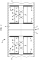
- FIG. 1 illustrates a weld zone purging installation that includes two identical water-degradable purge dam apparatus 12 constructed in accordance with an example embodiment of the disclosed subject matter.
- the two purge dam apparatus 12 are arranged to define a weld zone 14 that is to be purged of oxygen within a pipe assembly 16.
- the pipe assembly 16 includes a first (left-side) pipe 18 and second (right-side) pipe 20.
- the first and second pipes 18 and 20 have respective first and second pipe ends 22 and 24 that are to be butt-welded together at a root gap 26.
- One of the purge dam apparatus 12 is arranged inside the first pipe end 22 of the first pipe 18.
- the other purge dam apparatus 12 is arranged inside the second pipe end 24 of the second pipe 20.
- the purge dam apparatus 12 are spaced from the root gap 26 at a distance that is sufficient to prevent purge dam degradation due to the heat of the welding operation.
- Each purge dam apparatus 12 may be formed from one or more air flow blocking plate assemblies 28. If the purge dam apparatus 12 includes more than one blocking plate assembly 28, the blocking plate assemblies may either be interconnected or non-interconnected.
- An interconnected construction is shown in FIG. 1 , which depicts an embodiment wherein each purge dam apparatus 12 is formed as a ganged set of spaced-apart blocking plate assemblies 28. In the illustrated embodiment, the blocking plate assemblies 28 are ganged together by an interconnection assembly 30.
- Some or all of the components of the blocking plate assemblies 28 and the interconnection assembly 30 may be formed from water degradable materials so that the purge dam apparatus 12 can be sufficiently degraded using water or other aqueous fluids to enable purge dam removal from the pipe assembly 16 following welding.
- water degradable materials may be used. Suitable water degradable materials will be preferably designed to (1) provide low (or zero) air permeability for critical welding applications, (2) provide sufficient strength to withstand both purge gas pressure and bidirectional air flow pressures within the pipes 18 and 20, (3) allow the purge dam components to be easily formed and manipulated from flat sheet stock into their final shapes, and (4) degrade under hydrostatic pressure testing or flushing of the pipe structure with water or other aqueous fluids to facilitate purge dam removal following welding.
- Example water degradable materials include, but are not limited to, water degradable paper or board, a water degradable polymer, or a combination of water degradable paper or board and a water degradable polymer.
- Suitable water degradable paper and board materials are available from Aquasol Corporation of North Tonawanda, New York under the trademark Aquasol ® .
- the Aquasol ® brand paper and board products are water soluble and made of Sodium Carboxy Methyl cellulose and wooden pulp that dissolves rapidly and completely in most liquids, including water.
- a suitable water degradable polymer is polyvinyl alcohol (PVOH), which may be manufactured in film form or as a molded three-dimensional structure.
- water degradable material is paper board, polymer, or a combination of such materials
- one or more layers of the selected material may be fabricated into water degradable sheets of varying thickness.
- the sheet thicknesses may be selected according to the strength and flexibility requirements of the various structural components of the purge dam apparatus 12.
- a lamination process may be used to construct water degradable sheets having the required thickness.
- the water degradable sheets may be cut into any desired shape (prior to or after lamination) that is useful for purge dam formation, including but not limited to tubular shapes and circular shapes, as will now be described.
- a suitable water degradable adhesive may be used to combine the structural components of the purge dam apparatus 12.
- each blocking plate assembly 28 may have an outer blocking plate 28A. an inner blocking plate 28B and zero or more interior blocking plates 28C.
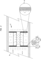
- Fig. 2 depicts an example embodiment in which there are five interior blocking plates 28C-1 through 28C-5. This embodiment thus provides a seven-plate stack of blocking plates in each blocking plate assembly 28.
- additional blocking plates may be added.
- fewer blocking plates could be used. For example, such an embodiment might only include the outer blocking plate 28A and the inner blocking plate 28B.
- the blocking plate assemblies 28 may be formed as a layered structure in which the various blocking plates 28A, 28B and 28C are bonded or otherwise secured together in a suitable manner.
- a water-degradable adhesive could be applied between the layers.
- Other fabrication techniques may also be used, including techniques that do not require the application of adhesive, such as heat bonding, etc.
- each blocking plate 28A, 28B and 28C may be substantially disk-shaped. However, other shapes could be used for purging structures that do not have circular cross-sections, such as ducts or other types of conduits that may be square, rectangular or of other shape.
- the thickness of each blocking plate 28A, 28B and 28C, as well as the total thickness of each blocking plate assembly 28, is a matter of design choice that will depend on various factors, including the size of the pipes 18 and 20 and the purge gas and air pressures that must be resisted by the purge dam apparatus 12. It should also be noted that the blocking plates 28A, 28B and 28C could be of varying thickness relative to each other.
- one or more of the plates 28A, 28B and 28C may be formed as a friction plate adapted to flexibly engage an inside wall of one of the first or second pipe ends 22 and 24.
- Fig. 2 depicts an embodiment in which the central interior blocking plate 28C-3 provides such a friction plate.
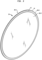
- Fig. 3 illustrates an example construction in which the friction plate 28C-3 is formed with a plurality of flexible sidewall members 32 on its periphery. The flexible members 32 are adapted to flexibly engage an inside wall of one of the first or second pipe ends 22 and 24, such that the purge dam apparatus 12 is self-retaining in the pipe assembly 16.
- the term "self-retaining” refers to the fact that no external retention components or materials, such as adhesive tape, glue, fasteners, etc., are required to retain the purge dam 12 apparatus in engagement with the pipe end inside walls.
- the desired self-retention property of the purge dam apparatus 12 is due to two factors. First, the diameter of the friction plate 28C-3 is somewhat larger than the inside diameter of the pipe ends 22 and 24. This forces the free ends of the flexible members 32 to bend when the purge dam apparatus 12 is installed. Second, the flexible members 32, as well as the remainder of the friction plate 28C-3, are sufficiently stiff to develop radial forces between the flexible members 32 and the pipe end inside walls as the flexible members bend during purge dam installation. These radial forces in turn create longitudinal friction forces along the pipe end inside walls that oppose air or purge gas pressures that might otherwise displace the purge dam 12 in the longitudinal direction within the pipe ends 22 and 24.
- the flexible members 32 comprise flexible finger-shaped tabs defined by slits in the friction plate member periphery 34.
- the slits may be formed using any suitable technique, such as die cutting.
- there are no appreciable gaps between the flexible members 32 such that bending the flexible members during purge dam installation does not allow an appreciable amount of purge gas to leave the weld zone 14 or air to enter the weld zone from within the pipes 18 and 20. It will be appreciated that other types of flexible members 32 may also be used.
- the blocking plates 28C-2 and 28C-4 stacked on each side of the friction plate 28C-3 serve as support plates that support the friction plate member 28C-3 and provide structural rigidity.
- FIG. 3 illustrates the support plates 28C-2 and 28C-4, but not the remaining blocking plates of the blocking plate assemblies 28. However, the remaining blocking plates do function to some extent as support plates. This includes the outer plate 28A and the interior plate 28C-1 on the left side of the friction plate 28C-3, and the interior plate 28C-5 and the inner plate 28B on the right side of the friction plate.
- Each of the support plate members 28A, 28C-1, 28C-2, 28C-4, 28C-5 and 28B have a periphery that may be aligned with a base of the friction disk flexible members 32 so as not to impede the desired flexing characteristic.
- FIG. 3 also illustrates what a purge dam apparatus 12 might look like if it included only a single blocking plate assembly.
- the support plates 28C-2 and 28C-4 could respectively serve as the outer blocking plate 28A and the inner blocking plate 28B, with the friction plate 28C-3 providing a single interior plate 28C.
- FIGS. 1-3 depict an embodiment in which the center blocking plate 28C-3 is a friction plate, any of the other blocking plates could be configured as friction plates, either alone or in combination with other blocking plates. If either the outer blocking plate 28A or the inner blocking plate 28B are configured as friction plates, there will be support plates stacked on only one side of the friction plate. For example, in FIG. 3 , this would be the case if the support plate 28C-4 were eliminated, such that the support plate 28C-2 serves as the outer blocking plate 28A and the friction plate 28C-3 serves as the inner blocking plate 28B.
- the purge dam apparatus 12 may be degraded and removed from the pipes 18 and 20 using water or other suitable aqueous fluid following a welding operation.
- FIG. 2 illustrates the application of water to the purge dam apparatus 12 so as to remove it from the pipe 18.
- one or more of the blocking plates 28A, 28B and 28C may include a plurality of fluid flow apertures that aid distribution of the aqueous fluid through the blocking plate assemblies.
- the inset view on the right side of FIG. 2 together with FIGS. 4 and 5A-5C , illustrate an embodiment wherein the interior blocking plates 28C-1 through 28C-5 are formed with such apertures.
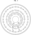
- the fluid flow apertures are numbered 1-5 to indicate the corresponding interior blocking plate in which they are formed.
- the apertures labeled with reference number 1 are all formed in the interior blocking plate 28C-1
- the apertures labeled with reference number 2 are all formed in the interior blocking plate 28C-2
- the apertures labeled with reference number 3 are all formed in the interior blocking plate 28C-3
- the apertures labeled with reference number 4 are all formed in the interior blocking plate 28C-4
- the apertures labeled with reference number 5 are all formed in the interior blocking plate 28C-5.
- the illustrated embodiment does not have fluid flow apertures in the outer blocking plate 28A or the inner blocking plate 28B, one or both of these blocking plates could have such apertures if so desired.
- the fluid flow apertures may be formed in any desired pattern and may be of any desired shape or size, depending on the manner in which the aqueous fluid is to be directed through the blocking plate assembly 28.
- the circular fluid flow aperture arrangement shown in FIG. 4 is merely one possible example. It will also be seen that FIG. 4 depicts circular fluid flow apertures of a particular size. However, other shapes and/or sizes may also be used for the fluid flow apertures.
- the purpose of the fluid flow apertures is to allow the aqueous fluid to distribute more rapidly and completely through the blocking plate assembly. Due to the water degrading properties of the blocking plate material, the aqueous fluid will migrate both longitudinally through the blocking plates and laterally between the interfaces between adj acent blocking plates. This is illustrated by the fluid flow arrows in FIGS. 5A-5C . In these drawing Figures, the aqueous fluid enters the blocking plate assembly 28 and passes through the outer blocking plate 28A, migrates through the interior blocking plates 28C-1 through 28C-5, then exits the blocking plate assembly by passing through the inner blocking plate 28B. Although, fluid migration will occur even without the fluid flow apertures, the apertures accelerate longitudinal fluid migration relative to lateral fluid migration by providing longitudinal vias through the blocking plates.
- the ratio of longitudinal fluid migration relative to lateral fluid migration may be controlled by selectively positioning the fluid flow apertures.
- the fluid flow apertures for a given pair of adjacent blocking plates i.e., blocking plates that are in interfacial engagement with each other
- FIG. 5B Laterally overlapping fluid flow apertures are shown by FIG. 5B in the interior blocking layers 28C-4 and 28C-5.
- FIG. 5C also shows laterally overlapping fluid flow apertures in the interior blocking layers 28C-1 and 28C-2, and in the interior blocking layers 28C-4 and 28C-5.
- the amount of lateral overlap will dictate the speed of longitudinal fluid migration.
- the fluid flow apertures in any given pair of adjacent blocking plates may be fully aligned with each other. Note that the illustrated embodiment does not use such a configuration because doing so may reduce the structural strength of the blocking plate assembly 28. Instead, as shown in FIGS. 4 and 5A , the fluid flow apertures are only fully aligned in different pairs of adjacent blocking plates. For example, in the outermost set of fluid flow apertures of FIG.
- the fluid flow apertures in the interior blocking plates 28C-2 and 28C-5 are fully aligned.
- the blocking plate assembly 28 By allowing only partially offsetting fluid flow apertures between adjacent blocking plates, with the remaining fluid flow apertures being fully laterally offset from each other, it is possible for the blocking plate assembly 28 to maintain substantially the same structural strength as a completely solid blocking plate assembly while still reducing purge dam degradation time.
- the fluid flow apertures may also be positioned to encourage fluid migration in desired lateral directions through the blocking plate assembly 28. For example, by laterally staggering the fluid flow apertures of successive blocking plates in a particular direction, the aqueous fluid can be induced to flow laterally in that direction. In Fig. 5A , aqueous fluid that passes through the outer blocking plate 28A will be directed to migrate in both the left and right lateral directions according to the aperture staggering in those directions.
- the interconnection assembly 30 may also include fluid flow apertures.
- the interconnection assembly 30 includes an inner interconnection structure 36 and an outer interconnection structure 38.
- the inner connection structure 36 includes a wall 36A surrounding a hollow interior 36B.
- the interconnection structure wall 36A may include a plurality of fluid flow apertures 36C to aid distribution of the aqueous fluid from the hollow interior 36B to an exterior region outside the interconnection structure wall 36A.
- the interconnection structure 36 may be of any desired cross-sectional shape, including circular, polygonal, etc.
- the blocking plate assemblies 28 may be attached to the interconnection structure 36 in any desired manner.
- the outer blocking plates 28A of the blocking plate assemblies 28 may be respectively attached to opposite ends of the interconnection structure wall 36A.
- the remaining blocking plates 28B and 28C may be formed with a central opening that attaches to a side portion of the interconnection structure wall 36A.
- a retainer 40 may be attached to the side portion of the interconnection structure wall 36A, abutting the inside face of the inner blocking plate 28B. Any suitable technique may be used to formed the above-described attachments, such as by using adhesive or other forms of bonding.
- the outer interconnection structure 38 surrounds the inner interconnection structure 36, and may be of any desired cross-sectional shape.
- the outer interconnection structure 38 may include a wall 38A that surrounds a hollow interior 38B.
- the ends of the wall 38A may be attached to the inside faces of the inner blocking plates 28B, such as by using adhesive or other suitable forms of bonding.
- the outer interconnection structure wall 38A may include a plurality of fluid flow apertures 38C to aid distribution of the aqueous fluid from the hollow interior 38B to an exterior region outside the interconnection structure wall 38A.
- each purge dam apparatus 12 may be respectively introduced into the pipe ends 22 and 24.
- the friction plate 28C-3 of each blocking plate assembly 28 may fit sufficiently tightly within the pipe ends 22 and 24 to require that the purge dam apparatus 2 be pounded into the pipe ends by applying a striking force against the end of the each purge dam apparatus (i.e., against the exposed outer blocking plate 28A).
- the pipe ends 22 and 24 may be brought together into the weld zone purging installation configuration of Fig. 1 , in which the weld zone 14 and root gap 26 are formed and the pipe ends are ready for welding. Purge gas introduced through the root gap 26 will be retained in the weld zone 14 by virtue of the blocking assemblies 28, and pressurized air will likewise be prevented from entering the weld zone from the interior of the first and second pipes 18 and 20.
- the purge dam apparatus 2 may be conveniently removed from the pipe assembly 16 using a water-based material passed through one or both of the pipes 18 and 20.
- the pipe assembly 16 may be flushed with water to degrade the purge dam apparatus 12, so that they break apart and flow along the pipes to an exit point, which may be a non-welded end of one of the pipes 18 or 20.
- the purge dam apparatus 12 may completely dissolve as a result of such flushing. In other constructions, the purge dam apparatus 12 may not fully dissolve, but will be sufficiently degraded to the point where they can be flushed or otherwise removed from the pipes.
Landscapes
- Engineering & Computer Science (AREA)
- Physics & Mathematics (AREA)
- Plasma & Fusion (AREA)
- Mechanical Engineering (AREA)
- Pipe Accessories (AREA)
- Arc Welding In General (AREA)
- Butt Welding And Welding Of Specific Article (AREA)
Description
- The present disclosure relates generally to inert gas welding. More particularly, the invention is directed to purge dams for retaining purge gas around a weld zone.
- By way of background, inert gas welding is a species of arc welding in which the molten weld pool is shielded from atmospheric contamination and oxidation by bathing it with an inert gas, such as Argon, or a mixture of Helium and Argon. Popular examples of inert gas welding include TIG (Tungsten Inert Gas) welding and MIG (Metal Inert Gas) welding.
- When welding together pipes and other enclosed structures using inert gas welding, it is important to purge the interior of the pipe or structure in the vicinity of the weld zone to prevent corrosion and the formation of oxides on the interior side of the weld pool. Purge dams are conventionally used for this purpose. For example, when butt-welding the ends of two pipe sections to form a consolidated pipe run, two purge dam structures are placed in the pipes, one in each pipe on either side of the weld zone. A purge gas can then be introduced into the area between the dams.
- Water degradable purge dams have been proposed that are made from water degradable paper. The advantage of water degradable paper purge dams is that they can be placed in close proximity to a weld zone, and then removed following welding by dissolving or otherwise degrading them with water introduced through the pipe. Insofar as pipe systems typically undergo hydrostatic pressure testing or flushing with water prior to use, water degradable purge dams can be used in many cases without any additional processing steps following welding. Such purge dams are typically formed from a sheet of water degradable paper that is formed into a concave shape in which a central portion of the purge dam spans across the diameter to the pipe to be welded and a peripheral edge portion of the purge dam engages the pipe wall so that it can be secured thereto, such as by using water soluble tape.
- Conventional water degradable purge dams as described above are designed for use with pipe installations with little or no air flow within the pipes being welded. However, there are some environments in which conventional water degradable purge dams are not practical because the purge dams cannot withstand air pressure fluctuations within the pipes. For example, underwater pipelines that are miles in length can develop large bidirectional air pressure surges. Undersea pipeline installation contractors sometimes refer to this phenomenon as "suck and blow." When fabricating such pipelines, the end of the existing portion of the pipeline is fixtured at the surface by a pipe-laying vessel that carries the next run of pipe, which itself may be several miles in length, on a spool. Inert gas welding to connect the ends of the two pipe sections is performed onboard the ship using a welding jig that aligns the pipe sections to form a welding root gap. However, it is first necessary to ensure that the bidirectional air flow within the pipe sections cannot enter the weld zone, where it would quickly displace the purge gas. This is typically done by inserting blocking members, made from a suitable foam material, into the ends of the pipe sections. Unfortunately, this practice has met with mixed success because the blocking member can dislodge if the air pressure fluctuations are large enough, and may be difficult to remove following welding.
-
EP2692470A1 is directed to a water-degradable welding purge dam apparatus for a high air flow environment. The purge dam apparatus includes first and second purge dam subassemblies adapted for installation in the ends of two pipes to be welded together. -
US3338499 is directed to a device for welding pipe ends that includes water soluble plugs or seals. -
US4674772 is directed to a soluble pipe spacer for spacing pipes to be welded together. The spacer is formed of a fluid soluble material such as salts of alkali metals and alkaline earth metals. -
EP0170402A1 is directed to a metal foil packing element for placement in a fluid stream to enhance contact between two fluids moving in opposing directions through the packing element, such as a gas rising and a liquid falling within a reaction chamber. The packing element comprises surfaces oriented to impart to different portions of the fluid stream different components of momentum which are normal to the predominant flow direction. The packing element further comprises intersection regions defined by the surfaces, each intersection region being arranged to cause different portions of the fluid stream having different momentum components to meet with a tendency to cancel the momentum components. The surfaces may be arranged in successive layers that are parallel to the longitudinal direction of fluid flow. Pyramids with apertures may be formed in the surfaces. The apertures promote fluid interchange and mixing and uniform distribution between the two sides of each layer. -
US6746651 is directed to an axial flow catalyst pack for catalytic decomposition of monopropellant fuels. The catalyst pack comprises a stack of very thin metal plates providing high surface area for catalytic decomposition of a fluid flowing axially from upstream to downstream through the stack. Each plate has flow-through passages of selected size and location to promote uniform flow and good surface contact with a catalyst surface on the plates. -
US20160259383 is directed to a continuous-flow loop heat pipe for cooling an electronic device (such as a smartphone). The loop heat pipe includes an evaporator configured to vaporize a working fluid, a condenser configured to liquefy the working fluid, a liquid line connecting the evaporator and the condenser, a porous body in the liquid line and the evaporator, and a vapor line connecting the evaporator and the condenser to form a loop together with the liquid line. The porous body is provided for the purpose of generating capillary forces that prevent vapor backflow from the vapor line and the evaporator to the liquid line. The porous body is a multi-layer metal structure having pores formed in each layer. The pores are arranged such that when the metal layers are stacked, the pores are aligned in a partially overlapping manner to form fine channels through which the working fluid permeates three-dimensionally through the body with the assistance of capillary force. - Applicant submits that there is presently a need for improvement in the construction of water-degradable purge dams, including for high air flow environments. What is required in particular is a purge dam apparatus that can be used in long pipelines that develop significant bidirectional air pressure fluctuations therein. It would be additionally desirable to improve the efficiency of purge dam degradation following welding. This would facilitate the construction of sturdy and robust water-degradable purge dams that are suitable for use in high air pressure environments, while ensuring that rapid and complete purge dam degradation occurs at purge dam removal time.
- A water-degradable welding purge dam apparatus for use during purging a weld zone is defined in
claim 1. - In an embodiment, the purge dam apparatus may include first and second ones of the blocking plate assembly. The blocking plate assemblies may be ganged together by an interconnection assembly to provide a ganged set of blocking plate assemblies. The interconnection assembly may be formed from one or more water degradable materials to further facilitate removal of the purge dam apparatus from the pipe assembly.
- In another aspect, a weld zone purging installation may be formed in a pipe assembly that includes first and second pipes having respective first and second pipe ends to be welded together at a root gap. A water-degradable purge dam apparatus as summarized above may be disposed in each of the first and second pipes proximate to the first and second pipe ends to define a weld zone that spans the root gap.
- The foregoing and other features and advantages will be apparent from the following more particular description of example embodiments, as illustrated in the accompanying Drawings, in which:
-
Fig. 1 is a cross-sectional centerline view showing a portion of a pipe assembly having installed therein a pair of purge dam apparatus that may be constructed in accordance an embodiment with the present disclosure; -
Fig. 2 is a cross-sectional centerline view showing a portion of one pipe of the pipe assembly ofFig. 1 having installed therein one of the purge dam apparatus ofFig. 1 ; -
Fig. 3 is a perspective view showing a friction plate component of the purge dam apparatus ofFig. 1 ; -
FIG. 4 is a diagrammatic plan view of a blocking plate assembly of the purge dam apparatus ofFig. 1 showing example fluid flow apertures that may be formed in one or more blocking plates therein; -
FIG. 5A is cross-sectional view taken alongline 5A-5A inFIG. 4 ; -
FIG. 5B is cross-sectional view taken alongline 5B-5B inFIG. 4 ; -
FIG. 5C is cross-sectional view taken alongline 5C-5C inFIG. 4 . - Turning now to the drawing figures, which are not necessarily to scale, like reference numbers are used to represent like elements in all of the several views.
FIG. 1 illustrates a weld zone purging installation that includes two identical water-degradablepurge dam apparatus 12 constructed in accordance with an example embodiment of the disclosed subject matter. In the illustrated installation, the twopurge dam apparatus 12 are arranged to define aweld zone 14 that is to be purged of oxygen within apipe assembly 16. Thepipe assembly 16 includes a first (left-side)pipe 18 and second (right-side)pipe 20. The first andsecond pipes root gap 26. One of thepurge dam apparatus 12 is arranged inside the first pipe end 22 of thefirst pipe 18. The otherpurge dam apparatus 12 is arranged inside thesecond pipe end 24 of thesecond pipe 20. Thepurge dam apparatus 12 are spaced from theroot gap 26 at a distance that is sufficient to prevent purge dam degradation due to the heat of the welding operation. - Each
purge dam apparatus 12 may be formed from one or more air flow blockingplate assemblies 28. If thepurge dam apparatus 12 includes more than one blockingplate assembly 28, the blocking plate assemblies may either be interconnected or non-interconnected. An interconnected construction is shown inFIG. 1 , which depicts an embodiment wherein eachpurge dam apparatus 12 is formed as a ganged set of spaced-apart blockingplate assemblies 28. In the illustrated embodiment, the blockingplate assemblies 28 are ganged together by aninterconnection assembly 30. - Some or all of the components of the blocking
plate assemblies 28 and theinterconnection assembly 30 may be formed from water degradable materials so that thepurge dam apparatus 12 can be sufficiently degraded using water or other aqueous fluids to enable purge dam removal from thepipe assembly 16 following welding. A variety of water degradable materials may be used. Suitable water degradable materials will be preferably designed to (1) provide low (or zero) air permeability for critical welding applications, (2) provide sufficient strength to withstand both purge gas pressure and bidirectional air flow pressures within thepipes - Example water degradable materials include, but are not limited to, water degradable paper or board, a water degradable polymer, or a combination of water degradable paper or board and a water degradable polymer. Suitable water degradable paper and board materials are available from Aquasol Corporation of North Tonawanda, New York under the trademark Aquasol®. The Aquasol® brand paper and board products are water soluble and made of Sodium Carboxy Methyl cellulose and wooden pulp that dissolves rapidly and completely in most liquids, including water. A suitable water degradable polymer is polyvinyl alcohol (PVOH), which may be manufactured in film form or as a molded three-dimensional structure. Regardless of whether the water degradable material is paper board, polymer, or a combination of such materials, one or more layers of the selected material may be fabricated into water degradable sheets of varying thickness. The sheet thicknesses may be selected according to the strength and flexibility requirements of the various structural components of the
purge dam apparatus 12. In an embodiment, a lamination process may be used to construct water degradable sheets having the required thickness. The water degradable sheets may be cut into any desired shape (prior to or after lamination) that is useful for purge dam formation, including but not limited to tubular shapes and circular shapes, as will now be described. A suitable water degradable adhesive may be used to combine the structural components of thepurge dam apparatus 12. - With additional reference now to
Fig. 2 , which illustrates a portion of the left-hand pipe 18, each blockingplate assembly 28 may have anouter blocking plate 28A. aninner blocking plate 28B and zero or moreinterior blocking plates 28C. By way of example only, and not by way of limitation,Fig. 2 depicts an example embodiment in which there are fiveinterior blocking plates 28C-1 through 28C-5. This embodiment thus provides a seven-plate stack of blocking plates in each blockingplate assembly 28. In some embodiments (not shown), additional blocking plates may be added. In other embodiments (not shown), fewer blocking plates could be used. For example, such an embodiment might only include theouter blocking plate 28A and theinner blocking plate 28B. - The blocking
plate assemblies 28 may be formed as a layered structure in which thevarious blocking plates - Because pipes tend to be cylindrical, the blocking
plates plate plate assembly 28, is a matter of design choice that will depend on various factors, including the size of thepipes purge dam apparatus 12. It should also be noted that the blockingplates - In an example embodiment, one or more of the
plates Fig. 2 depicts an embodiment in which the centralinterior blocking plate 28C-3 provides such a friction plate.Fig. 3 illustrates an example construction in which thefriction plate 28C-3 is formed with a plurality offlexible sidewall members 32 on its periphery. Theflexible members 32 are adapted to flexibly engage an inside wall of one of the first or second pipe ends 22 and 24, such that thepurge dam apparatus 12 is self-retaining in thepipe assembly 16. As used herein, the term "self-retaining" refers to the fact that no external retention components or materials, such as adhesive tape, glue, fasteners, etc., are required to retain thepurge dam 12 apparatus in engagement with the pipe end inside walls. The desired self-retention property of thepurge dam apparatus 12 is due to two factors. First, the diameter of thefriction plate 28C-3 is somewhat larger than the inside diameter of the pipe ends 22 and 24. This forces the free ends of theflexible members 32 to bend when thepurge dam apparatus 12 is installed. Second, theflexible members 32, as well as the remainder of thefriction plate 28C-3, are sufficiently stiff to develop radial forces between theflexible members 32 and the pipe end inside walls as the flexible members bend during purge dam installation. These radial forces in turn create longitudinal friction forces along the pipe end inside walls that oppose air or purge gas pressures that might otherwise displace thepurge dam 12 in the longitudinal direction within the pipe ends 22 and 24. - In the illustrated embodiment of
FIGS. 1-3 , theflexible members 32 comprise flexible finger-shaped tabs defined by slits in the frictionplate member periphery 34. The slits may be formed using any suitable technique, such as die cutting. Preferably, there are no appreciable gaps between theflexible members 32, such that bending the flexible members during purge dam installation does not allow an appreciable amount of purge gas to leave theweld zone 14 or air to enter the weld zone from within thepipes flexible members 32 may also be used. - As best shown in
FIGS. 2 and3 , the blockingplates 28C-2 and 28C-4 stacked on each side of thefriction plate 28C-3 serve as support plates that support thefriction plate member 28C-3 and provide structural rigidity. Note thatFIG. 3 illustrates thesupport plates 28C-2 and 28C-4, but not the remaining blocking plates of the blockingplate assemblies 28. However, the remaining blocking plates do function to some extent as support plates. This includes theouter plate 28A and theinterior plate 28C-1 on the left side of thefriction plate 28C-3, and theinterior plate 28C-5 and theinner plate 28B on the right side of the friction plate. Each of thesupport plate members flexible members 32 so as not to impede the desired flexing characteristic. -
FIG. 3 also illustrates what apurge dam apparatus 12 might look like if it included only a single blocking plate assembly. In such an embodiment, thesupport plates 28C-2 and 28C-4 could respectively serve as theouter blocking plate 28A and theinner blocking plate 28B, with thefriction plate 28C-3 providing a singleinterior plate 28C. It will be further appreciated that althoughFIGS. 1-3 depict an embodiment in which thecenter blocking plate 28C-3 is a friction plate, any of the other blocking plates could be configured as friction plates, either alone or in combination with other blocking plates. If either theouter blocking plate 28A or theinner blocking plate 28B are configured as friction plates, there will be support plates stacked on only one side of the friction plate. For example, inFIG. 3 , this would be the case if thesupport plate 28C-4 were eliminated, such that thesupport plate 28C-2 serves as theouter blocking plate 28A and thefriction plate 28C-3 serves as theinner blocking plate 28B. - As previously discussed, the
purge dam apparatus 12 may be degraded and removed from thepipes FIG. 2 illustrates the application of water to thepurge dam apparatus 12 so as to remove it from thepipe 18. In order to provide rapid and robust purge dam degradation, one or more of the blockingplates FIG. 2 , together withFIGS. 4 and5A-5C , illustrate an embodiment wherein theinterior blocking plates 28C-1 through 28C-5 are formed with such apertures. - In
FIG. 4 , the fluid flow apertures are numbered 1-5 to indicate the corresponding interior blocking plate in which they are formed. Thus, the apertures labeled withreference number 1 are all formed in theinterior blocking plate 28C-1, the apertures labeled withreference number 2 are all formed in theinterior blocking plate 28C-2, the apertures labeled withreference number 3 are all formed in theinterior blocking plate 28C-3, the apertures labeled withreference number 4 are all formed in theinterior blocking plate 28C-4, and the apertures labeled withreference number 5 are all formed in theinterior blocking plate 28C-5. Although the illustrated embodiment does not have fluid flow apertures in theouter blocking plate 28A or theinner blocking plate 28B, one or both of these blocking plates could have such apertures if so desired. - The fluid flow apertures may be formed in any desired pattern and may be of any desired shape or size, depending on the manner in which the aqueous fluid is to be directed through the blocking
plate assembly 28. The circular fluid flow aperture arrangement shown inFIG. 4 is merely one possible example. It will also be seen thatFIG. 4 depicts circular fluid flow apertures of a particular size. However, other shapes and/or sizes may also be used for the fluid flow apertures. - The purpose of the fluid flow apertures is to allow the aqueous fluid to distribute more rapidly and completely through the blocking plate assembly. Due to the water degrading properties of the blocking plate material, the aqueous fluid will migrate both longitudinally through the blocking plates and laterally between the interfaces between adj acent blocking plates. This is illustrated by the fluid flow arrows in
FIGS. 5A-5C . In these drawing Figures, the aqueous fluid enters the blockingplate assembly 28 and passes through theouter blocking plate 28A, migrates through theinterior blocking plates 28C-1 through 28C-5, then exits the blocking plate assembly by passing through theinner blocking plate 28B. Although, fluid migration will occur even without the fluid flow apertures, the apertures accelerate longitudinal fluid migration relative to lateral fluid migration by providing longitudinal vias through the blocking plates. - The ratio of longitudinal fluid migration relative to lateral fluid migration may be controlled by selectively positioning the fluid flow apertures. For example, as can be seen in
FIGS. 4 and5A-5C , the fluid flow apertures for a given pair of adjacent blocking plates (i.e., blocking plates that are in interfacial engagement with each other) may at least partially laterally overlap one another. This will increase longitudinal fluid migration relative to lateral fluid migration as compared to a configuration in which the fluid flow apertures are fully laterally misaligned relative to each other (as many of apertures are inFIGS. 4 and5A-5C ). - Laterally overlapping fluid flow apertures are shown by
FIG. 5B in the interior blocking layers 28C-4 and 28C-5.FIG. 5C also shows laterally overlapping fluid flow apertures in the interior blocking layers 28C-1 and 28C-2, and in the interior blocking layers 28C-4 and 28C-5. The amount of lateral overlap will dictate the speed of longitudinal fluid migration. To maximize the rate of longitudinal fluid migration, the fluid flow apertures in any given pair of adjacent blocking plates may be fully aligned with each other. Note that the illustrated embodiment does not use such a configuration because doing so may reduce the structural strength of the blockingplate assembly 28. Instead, as shown inFIGS. 4 and5A , the fluid flow apertures are only fully aligned in different pairs of adjacent blocking plates. For example, in the outermost set of fluid flow apertures ofFIG. 4 and in the corresponding cross-sectional illustration ofFig. 5A , the fluid flow apertures in theinterior blocking plates 28C-2 and 28C-5 are fully aligned. By allowing only partially offsetting fluid flow apertures between adjacent blocking plates, with the remaining fluid flow apertures being fully laterally offset from each other, it is possible for the blockingplate assembly 28 to maintain substantially the same structural strength as a completely solid blocking plate assembly while still reducing purge dam degradation time. - The fluid flow apertures may also be positioned to encourage fluid migration in desired lateral directions through the blocking
plate assembly 28. For example, by laterally staggering the fluid flow apertures of successive blocking plates in a particular direction, the aqueous fluid can be induced to flow laterally in that direction. InFig. 5A , aqueous fluid that passes through theouter blocking plate 28A will be directed to migrate in both the left and right lateral directions according to the aperture staggering in those directions. - Returning now to
Figs. 1-2 , theinterconnection assembly 30 may also include fluid flow apertures. In the illustrated embodiment, theinterconnection assembly 30 includes aninner interconnection structure 36 and anouter interconnection structure 38. Theinner connection structure 36 includes awall 36A surrounding ahollow interior 36B. If desired, theinterconnection structure wall 36A may include a plurality offluid flow apertures 36C to aid distribution of the aqueous fluid from thehollow interior 36B to an exterior region outside theinterconnection structure wall 36A. - The
interconnection structure 36 may be of any desired cross-sectional shape, including circular, polygonal, etc. The blockingplate assemblies 28 may be attached to theinterconnection structure 36 in any desired manner. For example, as shown inFigs. 1-2 , theouter blocking plates 28A of the blockingplate assemblies 28 may be respectively attached to opposite ends of theinterconnection structure wall 36A. The remainingblocking plates interconnection structure wall 36A. In order to better secure the interior andinner blocking plates retainer 40 may be attached to the side portion of theinterconnection structure wall 36A, abutting the inside face of theinner blocking plate 28B. Any suitable technique may be used to formed the above-described attachments, such as by using adhesive or other forms of bonding. - The
outer interconnection structure 38 surrounds theinner interconnection structure 36, and may be of any desired cross-sectional shape. Theouter interconnection structure 38 may include awall 38A that surrounds ahollow interior 38B. The ends of thewall 38A may be attached to the inside faces of theinner blocking plates 28B, such as by using adhesive or other suitable forms of bonding. If desired, the outerinterconnection structure wall 38A may include a plurality offluid flow apertures 38C to aid distribution of the aqueous fluid from thehollow interior 38B to an exterior region outside theinterconnection structure wall 38A. - Returning now to
Fig. 1 , installation of thepurge dam apparatus 12 in thepipe assembly 16 may be performed using the installation method now to be described. Initially, thepipes purge dam apparatus 12 may be respectively introduced into the pipe ends 22 and 24. Note that thefriction plate 28C-3 of each blockingplate assembly 28 may fit sufficiently tightly within the pipe ends 22 and 24 to require that thepurge dam apparatus 2 be pounded into the pipe ends by applying a striking force against the end of the each purge dam apparatus (i.e., against the exposedouter blocking plate 28A). - Once the
purge dam apparatus 12 are installed in thepipes Fig. 1 , in which theweld zone 14 androot gap 26 are formed and the pipe ends are ready for welding. Purge gas introduced through theroot gap 26 will be retained in theweld zone 14 by virtue of theblocking assemblies 28, and pressurized air will likewise be prevented from entering the weld zone from the interior of the first andsecond pipes - Once the pipe ends 22 and 24 are fully welded together at the
root gap 26, thepurge dam apparatus 2 may be conveniently removed from thepipe assembly 16 using a water-based material passed through one or both of thepipes pipe assembly 16 may be flushed with water to degrade thepurge dam apparatus 12, so that they break apart and flow along the pipes to an exit point, which may be a non-welded end of one of thepipes purge dam apparatus 12 may completely dissolve as a result of such flushing. In other constructions, thepurge dam apparatus 12 may not fully dissolve, but will be sufficiently degraded to the point where they can be flushed or otherwise removed from the pipes. - Accordingly, a water-degradable purge dam apparatus, together with a related weld zone purging installation, have been disclosed. While various embodiments have been described, it should be apparent that many variations and alternative embodiments could be implemented in accordance with the invention such as defined in the appended claims.
Claims (18)
- A water-degradable welding purge dam apparatus (12) for use during purging a weld zone (14) of a pipe assembly (16) comprising first and second pipes (18, 20) having respective first and second pipe ends (22, 24) to be welded together at a root gap (26), said purge dam apparatus (12) comprising:an air flow blocking plate assembly (28) having an outer blocking plate (28A), an inner blocking plate (28B), and zero or more interior blocking plates (28C);wherein in use, said air flow blocking plate assembly (28) blocking air flow therethrough during welding, the air flow blocking plate assembly (28)comprising one or more water degradable materials to facilitate removal of said purge dam apparatus (12) from said pipe assembly (16) using an aqueous fluid following welding; andcharacterized by:
at least one of said blocking plates (28A, 28B or 28C) comprising a plurality of fluid flow apertures (1-5) providing longitudinal vias through said at least one blocking plate (28A, 28B or 28C) to aid distribution of said aqueous fluid through said blocking plate assembly (28) to provide rapid and robust purge dam degradation following welding. - The purge dam apparatus of claim 1, wherein there are first and second ones of said blocking plate assembly (28) that are ganged together by an interconnection assembly (30) to provide a ganged set of spaced-apart air flow blocking plate assemblies (28), said interconnection assembly (30) comprising one or more water degradable materials to further facilitate removal of said purge dam apparatus (12) from said pipe assembly (16).
- The purge dam apparatus of claim 1, wherein said blocking plate assembly (28) comprises at least one pair of blocking plates (28A, 28B or 28C) in mutual facing engagement with each other, each blocking plate (28A, 28B or 28C) of said blocking plate pair having a plurality of said fluid flow apertures (1-5).
- The purge dam apparatus of claim 3, wherein at least some of said fluid flow apertures (1-5) in respective ones of said blocking plates (28A, 28B or 28C) in said blocking plate pair are partially laterally overlapping relative to each other, and wherein said blocking plate assembly further includes at least one additional blocking plate (28A, 28B or 28C).
- The purge dam apparatus of claim 3, wherein at least some of said fluid flow apertures (1-5) in respective ones of said blocking plates (28A, 28B or 28C) in said blocking plate pair are fully laterally misaligned relative to each other.
- The purge dam apparatus of claim 1, wherein said blocking plate assembly (28) comprises two or more pairs of blocking plates (28A, 28B or 28C) in mutual facing engagement with each other, each blocking plate (28A, 28B or 28C) of said two or more blocking plate pairs having a plurality of said fluid flow apertures (1-5).
- The purge dam apparatus of claim 6, wherein at least some of said fluid flow apertures (1-5) in blocking plates (28A, 28B or 28C) that are not part of the same blocking plate pair are partially laterally aligned relative to each other.
- The purge dam apparatus of claim 6, wherein at least some of said fluid flow apertures (1-5) in blocking plates (28A, 28B or 28C) that are not part of the same blocking plate pair are fully laterally aligned relative to each other.
- The purge dam apparatus of claim 1, wherein said blocking plate assembly (28) includes at least one interior blocking plate (28C) having said fluid flow apertures, and wherein said outer blocking plate (28A) and said inner blocking plate (28B) do not include said fluid flow apertures (1-5).
- The purge dam apparatus of claim 2, wherein said interconnection assembly (30) comprises an interconnection structure (36) having a wall (36A) surrounding a hollow interior (36B).
- The purge dam apparatus of claim 10, wherein said interconnection structure wall (36A) comprises a plurality of fluid flow apertures (1-5) to aid distribution of said aqueous fluid from said hollow interior (36B) to an exterior region outside said interconnection structure wall (36A).
- The purge dam apparatus of claim 2, wherein said interconnection assembly (30) comprises first and second interconnection structures (36, 38) that interconnect said blocking plate assemblies (28).
- The purge dam apparatus of claim 12, wherein said second interconnection structure (38) surrounds said first interconnection structure (36).
- The purge dam apparatus of claim 13, wherein said first and second interconnection structures (36, 38) each comprise a wall (36A, 38A) surrounding a hollow interior (36B, 38B), and one or both of said first and second interconnection structure wall (36A, 38A) comprise a plurality of fluid flow apertures (36C, 38C) to aid distribution of said aqueous fluid from said hollow interior (36B, 38B) to an exterior region outside said interconnection structure wall (36A, 38A).
- The purge dam apparatus of claim 1, wherein one or more of the blocking plates (28A, 28B or 28C) are formed as a friction plate (28A, 28B or 28C) having a plurality of flexible sidewall members (32) on its periphery adapted to flexibly engage an inside wall of one of said first or second pipe ends (22, 24).
- The purge dam apparatus of claim 15, wherein said flexible members (32) comprise flexible tabs defined by slits in said disk periphery (34).
- The purge dam apparatus of claim 16, wherein the blocking plates (28A, 28B or 28C) serve as support plates (28A, 28B or 28C) stacked on one or both sides of said friction plate (28A, 28B or 28C).
- The purge dam apparatus of claim 17, wherein said one or more support plates (28A, 28B or 28C) have a periphery (34) that is aligned with a base of said friction plate flexible tabs.
Applications Claiming Priority (2)
| Application Number | Priority Date | Filing Date | Title |
|---|---|---|---|
| US15/366,690 US10413990B2 (en) | 2016-12-01 | 2016-12-01 | Welding purge dam with apertured purge plates |
| PCT/US2017/057682 WO2018102045A2 (en) | 2016-12-01 | 2017-10-20 | Welding purge dam with apertured purge plates |
Publications (4)
| Publication Number | Publication Date |
|---|---|
| EP3548216A2 EP3548216A2 (en) | 2019-10-09 |
| EP3548216A4 EP3548216A4 (en) | 2020-08-05 |
| EP3548216C0 EP3548216C0 (en) | 2024-04-24 |
| EP3548216B1 true EP3548216B1 (en) | 2024-04-24 |
Family
ID=62240306
Family Applications (1)
| Application Number | Title | Priority Date | Filing Date |
|---|---|---|---|
| EP17876078.1A Active EP3548216B1 (en) | 2016-12-01 | 2017-10-20 | Welding purge dam with apertured purge plates |
Country Status (4)
| Country | Link |
|---|---|
| US (1) | US10413990B2 (en) |
| EP (1) | EP3548216B1 (en) |
| CA (1) | CA3045426C (en) |
| WO (1) | WO2018102045A2 (en) |
Families Citing this family (1)
| Publication number | Priority date | Publication date | Assignee | Title |
|---|---|---|---|---|
| US12257656B2 (en) * | 2021-01-27 | 2025-03-25 | Airgas, Inc. | Method for pipe purging |
Citations (1)
| Publication number | Priority date | Publication date | Assignee | Title |
|---|---|---|---|---|
| US8616432B1 (en) * | 2012-07-31 | 2013-12-31 | Michael Hacikyan | Welding purge dam for high air flow environment |
Family Cites Families (40)
| Publication number | Priority date | Publication date | Assignee | Title |
|---|---|---|---|---|
| US3338499A (en) | 1964-06-25 | 1967-08-29 | Edmund M Jaskiewicz | Device for welding pipe ends |
| US3736400A (en) | 1971-08-31 | 1973-05-29 | Gilbreth Co | Apparatus for damming pipe ends for welding |
| US4114655A (en) | 1976-06-18 | 1978-09-19 | Bloker Richard T | Protective plug for the ends of tubular cores |
| US4096372A (en) | 1976-11-24 | 1978-06-20 | Hallenbeck Emerson | Purge unit |
| US4415114A (en) | 1981-05-07 | 1983-11-15 | Hallenbeck Emerson | Purge gas unit with cones |
| CA1266823A (en) | 1984-06-26 | 1990-03-20 | Thomas W. Mix | Packing elements for enhancing liquid mixing |
| US4674772A (en) | 1985-04-25 | 1987-06-23 | Lycan Goodwin A | Soluble pipe spacer |
| US4916281A (en) | 1989-02-23 | 1990-04-10 | Haynes International, Inc. | Gas back-purging during welding of pipe |
| US5100043A (en) | 1990-11-15 | 1992-03-31 | Hallenbeck Emerson | Purge gas unit with bladders |
| JP2895260B2 (en) | 1991-03-15 | 1999-05-24 | 三菱重工業株式会社 | Pipe shield gas welding method |
| JPH0623685A (en) | 1991-10-02 | 1994-02-01 | Fujitsu Ltd | Automatic positioning device |
| US5187343A (en) | 1991-10-30 | 1993-02-16 | Edwards Thomas W | Purge block for pipe welding |
| US5361972A (en) | 1992-12-21 | 1994-11-08 | Barker Michael R | Purge strap for welding |
| US5390846A (en) | 1993-08-11 | 1995-02-21 | Thode; Jonathan E. | Welding gas purging apparatus and method |
| WO1996001720A1 (en) | 1994-07-12 | 1996-01-25 | Westinghouse Electric Corporation | Pipe clamping device |
| JPH0910933A (en) | 1995-06-28 | 1997-01-14 | Ishikawajima Harima Heavy Ind Co Ltd | Water-soluble paper stopper for pipe welding |
| US5669547A (en) | 1995-09-27 | 1997-09-23 | Praxair Technology, Inc. | Apparatus and method for supplying inert gas to a welding location |
| KR200159923Y1 (en) | 1996-02-06 | 1999-11-01 | 장용균 | sticker |
| US5785235A (en) | 1996-05-24 | 1998-07-28 | Beatty; Joel Winford | Purge block |
| US6010001A (en) | 1997-11-21 | 2000-01-04 | The Procter & Gamble Company | Individual packaging for hygienic wiping |
| US6746651B1 (en) * | 1999-08-10 | 2004-06-08 | Aerojet-General Corporation | Axial flow catalyst pack |
| KR200179895Y1 (en) | 1999-11-22 | 2000-04-15 | 박승근 | Paper cup having preventing system of leaking water for union cutting parts |
| US7922984B2 (en) | 2000-02-18 | 2011-04-12 | Selective Micro Technologies, Llc | Apparatus and method for controlled delivery of a gas |
| JP3825345B2 (en) | 2002-03-15 | 2006-09-27 | 日揮株式会社 | Welding method for piping |
| US6743334B2 (en) | 2002-06-11 | 2004-06-01 | Metso Paper Karlstad Aktiebolag (Ab) | Method and apparatus for making a tissue paper with improved tactile qualities while improving the reel-up process for a high bulk web |
| US7146782B2 (en) | 2003-08-19 | 2006-12-12 | Huhtamaki Consumer Packaging, Inc. | Method of sealing a plug with a food sauce dispensing cartridge |
| US7112358B1 (en) | 2004-05-03 | 2006-09-26 | Michael Hacikyan | Self-adhesive purge dam for retaining purge gas around a weld zone |
| US7632556B1 (en) | 2004-05-03 | 2009-12-15 | Michael Hacikyan | Self-adhesive purge dam for retaining purge gas around a weld zone |
| US20060068142A1 (en) | 2004-09-27 | 2006-03-30 | Michael Hacikyan | Welding tape and related taping method |
| US8061388B1 (en) | 2004-11-08 | 2011-11-22 | O'brien Daniel Edward | Chemical barrier plug assembly and manufacturing and dislodgement methods for hydrostatic and pneumatic testing |
| US20080251132A1 (en) | 2007-04-10 | 2008-10-16 | Michael Eric Bentley | Flexible inflatable purge block for high purity welds |
| US8647731B2 (en) | 2008-08-21 | 2014-02-11 | Michael Hacikyan | Purge dam for retaining purge gas around a weld zone |
| JP5232633B2 (en) | 2008-12-26 | 2013-07-10 | 三菱重工業株式会社 | Pipe welding method |
| US8835808B2 (en) | 2010-03-01 | 2014-09-16 | John M. Boatner, JR. | Apparatus for joining sections of pipe |
| US8292161B2 (en) | 2010-04-06 | 2012-10-23 | Michael Hacikyan | Welding alignment and spacing article |
| KR101139196B1 (en) | 2012-03-07 | 2012-04-26 | 박진우 | Purging apparatus for pipe welding |
| US8540137B1 (en) | 2012-07-31 | 2013-09-24 | Michael Hacikyan | Adhesiveless welding purge dam |
| JP6021851B2 (en) | 2013-05-10 | 2016-11-09 | 富士フイルム株式会社 | Hygroscopic material, manufacturing method thereof and packaging material |
| WO2015087451A1 (en) * | 2013-12-13 | 2015-06-18 | 富士通株式会社 | Loop-type heat pipe, method for manufacturing same, and electronic equipment |
| US9586284B2 (en) | 2014-09-17 | 2017-03-07 | Coke Evans | Purge dam and method of use |
-
2016
- 2016-12-01 US US15/366,690 patent/US10413990B2/en active Active
-
2017
- 2017-10-20 CA CA3045426A patent/CA3045426C/en active Active
- 2017-10-20 EP EP17876078.1A patent/EP3548216B1/en active Active
- 2017-10-20 WO PCT/US2017/057682 patent/WO2018102045A2/en not_active Ceased
Patent Citations (1)
| Publication number | Priority date | Publication date | Assignee | Title |
|---|---|---|---|---|
| US8616432B1 (en) * | 2012-07-31 | 2013-12-31 | Michael Hacikyan | Welding purge dam for high air flow environment |
Also Published As
| Publication number | Publication date |
|---|---|
| EP3548216C0 (en) | 2024-04-24 |
| CA3045426C (en) | 2020-10-13 |
| CA3045426A1 (en) | 2018-06-07 |
| WO2018102045A2 (en) | 2018-06-07 |
| US20180154474A1 (en) | 2018-06-07 |
| EP3548216A4 (en) | 2020-08-05 |
| WO2018102045A3 (en) | 2018-07-26 |
| EP3548216A2 (en) | 2019-10-09 |
| US10413990B2 (en) | 2019-09-17 |
Similar Documents
| Publication | Publication Date | Title |
|---|---|---|
| EP2692470B1 (en) | Welding purge dam for high air flow environment | |
| US8881768B2 (en) | Fluid flow control devices and systems, and methods of flowing fluids therethrough | |
| US8540137B1 (en) | Adhesiveless welding purge dam | |
| US20170067579A1 (en) | Design of tortuous path control valve trim | |
| JP2007192533A (en) | Fuel plate assembly and deoxidizing device | |
| JP2016028813A (en) | Gas separation membrane module with improved gas seal | |
| CA2763605C (en) | Fluid flow control devices and systems, and methods of flowing fluids therethrough | |
| CA3045426C (en) | Welding purge dam with apertured purge plates | |
| KR102512692B1 (en) | Gas Separation Membrane Modules for Reactive Gas Service | |
| CN111683869A (en) | Reduced viscous cladding | |
| US8292161B2 (en) | Welding alignment and spacing article | |
| US20150144309A1 (en) | Flattened Envelope Heat Exchanger | |
| JP2017177106A (en) | Filter device, filter material and filter material sheet | |
| KR102512455B1 (en) | Gas Separation Membrane Modules for Reactive Gas Service | |
| JP3195760U (en) | Double pipe | |
| JP6912161B2 (en) | Channel device and droplet formation method | |
| WO2015081274A1 (en) | Flattened envelope heat exchanger | |
| CN117446212A (en) | A board management device for high acceleration environments | |
| BR102017018910A2 (en) | COMPOSITE SUPPORT RING FOR TOP WELDS AND SYSTEM EMPLOYING THE RING ON THE MANUFACTURE OF INTERNAL COATED METAL PIPE SOLDERED JOINTS WITH HEAT SENSITIVE MATERIALS | |
| CN210625426U (en) | Novel printed circuit board type heat exchanger core containing combined flow channel | |
| JP7210332B2 (en) | Beam reinforcing member, beam reinforcing method and beam reinforcing structure | |
| US8426001B2 (en) | Welding alignment and spacing article | |
| KR102763901B1 (en) | Devices, systems and methods for filters | |
| DE10339972A1 (en) | Microfluidic component used as micro heat exchanger in fuel cell system comprises two flat metallic components connected together in a gas-tight manner using laser welding and having structures for guiding fluids | |
| JP2013174296A (en) | Joint structure and joint method |
Legal Events
| Date | Code | Title | Description |
|---|---|---|---|
| STAA | Information on the status of an ep patent application or granted ep patent |
Free format text: STATUS: THE INTERNATIONAL PUBLICATION HAS BEEN MADE |
|
| PUAI | Public reference made under article 153(3) epc to a published international application that has entered the european phase |
Free format text: ORIGINAL CODE: 0009012 |
|
| STAA | Information on the status of an ep patent application or granted ep patent |
Free format text: STATUS: REQUEST FOR EXAMINATION WAS MADE |
|
| 17P | Request for examination filed |
Effective date: 20190516 |
|
| AK | Designated contracting states |
Kind code of ref document: A2 Designated state(s): AL AT BE BG CH CY CZ DE DK EE ES FI FR GB GR HR HU IE IS IT LI LT LU LV MC MK MT NL NO PL PT RO RS SE SI SK SM TR |
|
| AX | Request for extension of the european patent |
Extension state: BA ME |
|
| DAV | Request for validation of the european patent (deleted) | ||
| DAX | Request for extension of the european patent (deleted) | ||
| A4 | Supplementary search report drawn up and despatched |
Effective date: 20200703 |
|
| RIC1 | Information provided on ipc code assigned before grant |
Ipc: B23K 101/10 20060101ALI20200629BHEP Ipc: B32B 7/00 20190101ALI20200629BHEP Ipc: B65D 65/46 20060101ALN20200629BHEP Ipc: B32B 27/00 20060101ALI20200629BHEP Ipc: B23K 9/00 20060101ALI20200629BHEP Ipc: B23K 9/028 20060101ALI20200629BHEP Ipc: B23K 9/173 20060101ALI20200629BHEP Ipc: B32B 29/00 20060101ALI20200629BHEP Ipc: B23K 9/32 20060101AFI20200629BHEP Ipc: B23K 101/06 20060101ALI20200629BHEP Ipc: B23K 9/167 20060101ALI20200629BHEP Ipc: B23K 9/16 20060101ALI20200629BHEP |
|
| STAA | Information on the status of an ep patent application or granted ep patent |
Free format text: STATUS: EXAMINATION IS IN PROGRESS |
|
| 17Q | First examination report despatched |
Effective date: 20221007 |
|
| RAP1 | Party data changed (applicant data changed or rights of an application transferred) |
Owner name: AQUASOL CORPORATION, LLC |
|
| RIN1 | Information on inventor provided before grant (corrected) |
Inventor name: HACIKYAN, MICHAEL |
|
| RIC1 | Information provided on ipc code assigned before grant |
Ipc: B65D 65/46 20060101ALN20230831BHEP Ipc: B32B 27/30 20060101ALI20230831BHEP Ipc: B32B 27/10 20060101ALI20230831BHEP Ipc: B32B 27/08 20060101ALI20230831BHEP Ipc: B32B 7/12 20060101ALI20230831BHEP Ipc: B32B 3/26 20060101ALI20230831BHEP Ipc: B23K 9/173 20060101ALI20230831BHEP Ipc: B23K 9/167 20060101ALI20230831BHEP Ipc: B23K 101/06 20060101ALI20230831BHEP Ipc: B32B 29/00 20060101ALI20230831BHEP Ipc: B32B 27/00 20060101ALI20230831BHEP Ipc: B32B 7/00 20190101ALI20230831BHEP Ipc: B23K 9/028 20060101ALI20230831BHEP Ipc: B23K 9/00 20060101ALI20230831BHEP Ipc: B23K 101/10 20060101ALI20230831BHEP Ipc: B23K 9/16 20060101ALI20230831BHEP Ipc: B23K 9/32 20060101AFI20230831BHEP |
|
| GRAP | Despatch of communication of intention to grant a patent |
Free format text: ORIGINAL CODE: EPIDOSNIGR1 |
|
| STAA | Information on the status of an ep patent application or granted ep patent |
Free format text: STATUS: GRANT OF PATENT IS INTENDED |
|
| INTG | Intention to grant announced |
Effective date: 20231013 |
|
| RIC1 | Information provided on ipc code assigned before grant |
Ipc: B65D 65/46 20060101ALN20231004BHEP Ipc: B32B 27/30 20060101ALI20231004BHEP Ipc: B32B 27/10 20060101ALI20231004BHEP Ipc: B32B 27/08 20060101ALI20231004BHEP Ipc: B32B 7/12 20060101ALI20231004BHEP Ipc: B32B 3/26 20060101ALI20231004BHEP Ipc: B23K 9/173 20060101ALI20231004BHEP Ipc: B23K 9/167 20060101ALI20231004BHEP Ipc: B23K 101/06 20060101ALI20231004BHEP Ipc: B32B 29/00 20060101ALI20231004BHEP Ipc: B32B 27/00 20060101ALI20231004BHEP Ipc: B32B 7/00 20190101ALI20231004BHEP Ipc: B23K 9/028 20060101ALI20231004BHEP Ipc: B23K 9/00 20060101ALI20231004BHEP Ipc: B23K 101/10 20060101ALI20231004BHEP Ipc: B23K 9/16 20060101ALI20231004BHEP Ipc: B23K 9/32 20060101AFI20231004BHEP |
|
| GRAJ | Information related to disapproval of communication of intention to grant by the applicant or resumption of examination proceedings by the epo deleted |
Free format text: ORIGINAL CODE: EPIDOSDIGR1 |
|
| STAA | Information on the status of an ep patent application or granted ep patent |
Free format text: STATUS: EXAMINATION IS IN PROGRESS |
|
| GRAP | Despatch of communication of intention to grant a patent |
Free format text: ORIGINAL CODE: EPIDOSNIGR1 |
|
| STAA | Information on the status of an ep patent application or granted ep patent |
Free format text: STATUS: GRANT OF PATENT IS INTENDED |
|
| INTC | Intention to grant announced (deleted) | ||
| RIC1 | Information provided on ipc code assigned before grant |
Ipc: B65D 65/46 20060101ALN20231128BHEP Ipc: B32B 27/30 20060101ALI20231128BHEP Ipc: B32B 27/10 20060101ALI20231128BHEP Ipc: B32B 27/08 20060101ALI20231128BHEP Ipc: B32B 7/12 20060101ALI20231128BHEP Ipc: B32B 3/26 20060101ALI20231128BHEP Ipc: B23K 9/173 20060101ALI20231128BHEP Ipc: B23K 9/167 20060101ALI20231128BHEP Ipc: B23K 101/06 20060101ALI20231128BHEP Ipc: B32B 29/00 20060101ALI20231128BHEP Ipc: B32B 27/00 20060101ALI20231128BHEP Ipc: B32B 7/00 20190101ALI20231128BHEP Ipc: B23K 9/028 20060101ALI20231128BHEP Ipc: B23K 9/00 20060101ALI20231128BHEP Ipc: B23K 101/10 20060101ALI20231128BHEP Ipc: B23K 9/16 20060101ALI20231128BHEP Ipc: B23K 9/32 20060101AFI20231128BHEP |
|
| INTG | Intention to grant announced |
Effective date: 20231219 |
|
| GRAS | Grant fee paid |
Free format text: ORIGINAL CODE: EPIDOSNIGR3 |
|
| GRAA | (expected) grant |
Free format text: ORIGINAL CODE: 0009210 |
|
| STAA | Information on the status of an ep patent application or granted ep patent |
Free format text: STATUS: THE PATENT HAS BEEN GRANTED |
|
| AK | Designated contracting states |
Kind code of ref document: B1 Designated state(s): AL AT BE BG CH CY CZ DE DK EE ES FI FR GB GR HR HU IE IS IT LI LT LU LV MC MK MT NL NO PL PT RO RS SE SI SK SM TR |
|
| REG | Reference to a national code |
Ref country code: GB Ref legal event code: FG4D |
|
| REG | Reference to a national code |
Ref country code: CH Ref legal event code: EP |
|
| REG | Reference to a national code |
Ref country code: DE Ref legal event code: R096 Ref document number: 602017081391 Country of ref document: DE |
|
| REG | Reference to a national code |
Ref country code: IE Ref legal event code: FG4D |
|
| U01 | Request for unitary effect filed |
Effective date: 20240509 |
|
| U07 | Unitary effect registered |
Designated state(s): AT BE BG DE DK EE FI FR IT LT LU LV MT NL PT SE SI Effective date: 20240522 |
|
| PG25 | Lapsed in a contracting state [announced via postgrant information from national office to epo] |
Ref country code: IS Free format text: LAPSE BECAUSE OF FAILURE TO SUBMIT A TRANSLATION OF THE DESCRIPTION OR TO PAY THE FEE WITHIN THE PRESCRIBED TIME-LIMIT Effective date: 20240824 |
|
| PG25 | Lapsed in a contracting state [announced via postgrant information from national office to epo] |
Ref country code: HR Free format text: LAPSE BECAUSE OF FAILURE TO SUBMIT A TRANSLATION OF THE DESCRIPTION OR TO PAY THE FEE WITHIN THE PRESCRIBED TIME-LIMIT Effective date: 20240424 |
|
| PG25 | Lapsed in a contracting state [announced via postgrant information from national office to epo] |
Ref country code: GR Free format text: LAPSE BECAUSE OF FAILURE TO SUBMIT A TRANSLATION OF THE DESCRIPTION OR TO PAY THE FEE WITHIN THE PRESCRIBED TIME-LIMIT Effective date: 20240725 |
|
| PG25 | Lapsed in a contracting state [announced via postgrant information from national office to epo] |
Ref country code: ES Free format text: LAPSE BECAUSE OF FAILURE TO SUBMIT A TRANSLATION OF THE DESCRIPTION OR TO PAY THE FEE WITHIN THE PRESCRIBED TIME-LIMIT Effective date: 20240424 |
|
| PG25 | Lapsed in a contracting state [announced via postgrant information from national office to epo] |
Ref country code: PL Free format text: LAPSE BECAUSE OF FAILURE TO SUBMIT A TRANSLATION OF THE DESCRIPTION OR TO PAY THE FEE WITHIN THE PRESCRIBED TIME-LIMIT Effective date: 20240424 |
|
| PG25 | Lapsed in a contracting state [announced via postgrant information from national office to epo] |
Ref country code: PL Free format text: LAPSE BECAUSE OF FAILURE TO SUBMIT A TRANSLATION OF THE DESCRIPTION OR TO PAY THE FEE WITHIN THE PRESCRIBED TIME-LIMIT Effective date: 20240424 Ref country code: IS Free format text: LAPSE BECAUSE OF FAILURE TO SUBMIT A TRANSLATION OF THE DESCRIPTION OR TO PAY THE FEE WITHIN THE PRESCRIBED TIME-LIMIT Effective date: 20240824 Ref country code: HR Free format text: LAPSE BECAUSE OF FAILURE TO SUBMIT A TRANSLATION OF THE DESCRIPTION OR TO PAY THE FEE WITHIN THE PRESCRIBED TIME-LIMIT Effective date: 20240424 Ref country code: GR Free format text: LAPSE BECAUSE OF FAILURE TO SUBMIT A TRANSLATION OF THE DESCRIPTION OR TO PAY THE FEE WITHIN THE PRESCRIBED TIME-LIMIT Effective date: 20240725 Ref country code: ES Free format text: LAPSE BECAUSE OF FAILURE TO SUBMIT A TRANSLATION OF THE DESCRIPTION OR TO PAY THE FEE WITHIN THE PRESCRIBED TIME-LIMIT Effective date: 20240424 Ref country code: RS Free format text: LAPSE BECAUSE OF FAILURE TO SUBMIT A TRANSLATION OF THE DESCRIPTION OR TO PAY THE FEE WITHIN THE PRESCRIBED TIME-LIMIT Effective date: 20240724 |
|
| U20 | Renewal fee for the european patent with unitary effect paid |
Year of fee payment: 8 Effective date: 20241009 |
|
| PG25 | Lapsed in a contracting state [announced via postgrant information from national office to epo] |
Ref country code: CZ Free format text: LAPSE BECAUSE OF FAILURE TO SUBMIT A TRANSLATION OF THE DESCRIPTION OR TO PAY THE FEE WITHIN THE PRESCRIBED TIME-LIMIT Effective date: 20240424 |
|
| PG25 | Lapsed in a contracting state [announced via postgrant information from national office to epo] |
Ref country code: RO Free format text: LAPSE BECAUSE OF FAILURE TO SUBMIT A TRANSLATION OF THE DESCRIPTION OR TO PAY THE FEE WITHIN THE PRESCRIBED TIME-LIMIT Effective date: 20240424 Ref country code: SK Free format text: LAPSE BECAUSE OF FAILURE TO SUBMIT A TRANSLATION OF THE DESCRIPTION OR TO PAY THE FEE WITHIN THE PRESCRIBED TIME-LIMIT Effective date: 20240424 |
|
| REG | Reference to a national code |
Ref country code: DE Ref legal event code: R097 Ref document number: 602017081391 Country of ref document: DE |
|
| PG25 | Lapsed in a contracting state [announced via postgrant information from national office to epo] |
Ref country code: SM Free format text: LAPSE BECAUSE OF FAILURE TO SUBMIT A TRANSLATION OF THE DESCRIPTION OR TO PAY THE FEE WITHIN THE PRESCRIBED TIME-LIMIT Effective date: 20240424 |
|
| PG25 | Lapsed in a contracting state [announced via postgrant information from national office to epo] |
Ref country code: SM Free format text: LAPSE BECAUSE OF FAILURE TO SUBMIT A TRANSLATION OF THE DESCRIPTION OR TO PAY THE FEE WITHIN THE PRESCRIBED TIME-LIMIT Effective date: 20240424 Ref country code: SK Free format text: LAPSE BECAUSE OF FAILURE TO SUBMIT A TRANSLATION OF THE DESCRIPTION OR TO PAY THE FEE WITHIN THE PRESCRIBED TIME-LIMIT Effective date: 20240424 Ref country code: RO Free format text: LAPSE BECAUSE OF FAILURE TO SUBMIT A TRANSLATION OF THE DESCRIPTION OR TO PAY THE FEE WITHIN THE PRESCRIBED TIME-LIMIT Effective date: 20240424 Ref country code: CZ Free format text: LAPSE BECAUSE OF FAILURE TO SUBMIT A TRANSLATION OF THE DESCRIPTION OR TO PAY THE FEE WITHIN THE PRESCRIBED TIME-LIMIT Effective date: 20240424 |
|
| PLBE | No opposition filed within time limit |
Free format text: ORIGINAL CODE: 0009261 |
|
| STAA | Information on the status of an ep patent application or granted ep patent |
Free format text: STATUS: NO OPPOSITION FILED WITHIN TIME LIMIT |
|
| 26N | No opposition filed |
Effective date: 20250127 |
|
| REG | Reference to a national code |
Ref country code: CH Ref legal event code: PL |
|
| PG25 | Lapsed in a contracting state [announced via postgrant information from national office to epo] |
Ref country code: MC Free format text: LAPSE BECAUSE OF FAILURE TO SUBMIT A TRANSLATION OF THE DESCRIPTION OR TO PAY THE FEE WITHIN THE PRESCRIBED TIME-LIMIT Effective date: 20240424 |
|
| PG25 | Lapsed in a contracting state [announced via postgrant information from national office to epo] |
Ref country code: CH Free format text: LAPSE BECAUSE OF NON-PAYMENT OF DUE FEES Effective date: 20241031 |
|
| U20 | Renewal fee for the european patent with unitary effect paid |
Year of fee payment: 9 Effective date: 20251014 |
|
| PGFP | Annual fee paid to national office [announced via postgrant information from national office to epo] |
Ref country code: GB Payment date: 20251014 Year of fee payment: 9 |
|
| PGFP | Annual fee paid to national office [announced via postgrant information from national office to epo] |
Ref country code: NO Payment date: 20251029 Year of fee payment: 9 |
|
| PGFP | Annual fee paid to national office [announced via postgrant information from national office to epo] |
Ref country code: IE Payment date: 20251027 Year of fee payment: 9 |
|
| PG25 | Lapsed in a contracting state [announced via postgrant information from national office to epo] |
Ref country code: CY Free format text: LAPSE BECAUSE OF FAILURE TO SUBMIT A TRANSLATION OF THE DESCRIPTION OR TO PAY THE FEE WITHIN THE PRESCRIBED TIME-LIMIT; INVALID AB INITIO Effective date: 20171020 |
|
| PG25 | Lapsed in a contracting state [announced via postgrant information from national office to epo] |
Ref country code: HU Free format text: LAPSE BECAUSE OF FAILURE TO SUBMIT A TRANSLATION OF THE DESCRIPTION OR TO PAY THE FEE WITHIN THE PRESCRIBED TIME-LIMIT; INVALID AB INITIO Effective date: 20171020 |