EP3548137B1 - Cochlear implants including electrode arrays and methods of making the same - Google Patents
Cochlear implants including electrode arrays and methods of making the same Download PDFInfo
- Publication number
- EP3548137B1 EP3548137B1 EP17817596.4A EP17817596A EP3548137B1 EP 3548137 B1 EP3548137 B1 EP 3548137B1 EP 17817596 A EP17817596 A EP 17817596A EP 3548137 B1 EP3548137 B1 EP 3548137B1
- Authority
- EP
- European Patent Office
- Prior art keywords
- contact
- mold
- contacts
- carrier
- electrically conductive
- Prior art date
- Legal status (The legal status is an assumption and is not a legal conclusion. Google has not performed a legal analysis and makes no representation as to the accuracy of the status listed.)
- Active
Links
Images




Classifications
-
- A—HUMAN NECESSITIES
- A61—MEDICAL OR VETERINARY SCIENCE; HYGIENE
- A61N—ELECTROTHERAPY; MAGNETOTHERAPY; RADIATION THERAPY; ULTRASOUND THERAPY
- A61N1/00—Electrotherapy; Circuits therefor
- A61N1/02—Details
- A61N1/04—Electrodes
- A61N1/05—Electrodes for implantation or insertion into the body, e.g. heart electrode
- A61N1/0526—Head electrodes
- A61N1/0541—Cochlear electrodes
-
- A—HUMAN NECESSITIES
- A61—MEDICAL OR VETERINARY SCIENCE; HYGIENE
- A61N—ELECTROTHERAPY; MAGNETOTHERAPY; RADIATION THERAPY; ULTRASOUND THERAPY
- A61N1/00—Electrotherapy; Circuits therefor
- A61N1/18—Applying electric currents by contact electrodes
- A61N1/32—Applying electric currents by contact electrodes alternating or intermittent currents
- A61N1/36—Applying electric currents by contact electrodes alternating or intermittent currents for stimulation
- A61N1/36036—Applying electric currents by contact electrodes alternating or intermittent currents for stimulation of the outer, middle or inner ear
- A61N1/36038—Cochlear stimulation
-
- A—HUMAN NECESSITIES
- A61—MEDICAL OR VETERINARY SCIENCE; HYGIENE
- A61N—ELECTROTHERAPY; MAGNETOTHERAPY; RADIATION THERAPY; ULTRASOUND THERAPY
- A61N1/00—Electrotherapy; Circuits therefor
- A61N1/18—Applying electric currents by contact electrodes
- A61N1/32—Applying electric currents by contact electrodes alternating or intermittent currents
- A61N1/36—Applying electric currents by contact electrodes alternating or intermittent currents for stimulation
- A61N1/372—Arrangements in connection with the implantation of stimulators
- A61N1/375—Constructional arrangements, e.g. casings
- A61N1/3752—Details of casing-lead connections
Definitions
- the present disclosure relates generally to the implantable portion of implantable cochlear stimulation (or "ICS") systems and, in particular, to electrode arrays.
- ICS implantable cochlear stimulation
- ICS systems are used to help the profoundly deaf perceive a sensation of sound by directly exciting the intact auditory nerve with controlled impulses of electrical current.
- Ambient sound pressure waves are picked up by an externally worn microphone and converted to electrical signals.
- the electrical signals are processed by a sound processor, converted to a pulse sequence having varying pulse widths, rates, and/or amplitudes, and transmitted to an implanted receiver circuit of the ICS system.
- the implanted receiver circuit is connected to an implantable lead with an electrode array that is inserted into the cochlea of the inner ear, and electrical stimulation current is applied to varying electrode combinations to create a perception of sound.
- the electrode array may, alternatively, be directly inserted into the cochlear nerve without residing in the cochlea.
- ICS sound processors include, but are not limited to, the HarmonyTM BTE sound processor, the NaidaTM CI Q Series sound processor and the NeptuneTM body worn sound processor, which are available from Advanced Bionics.
- some ICS systems include an implantable cochlear stimulator (or "cochlear implant") having a lead with an electrode array, a sound processor unit (e.g., a body worn processor or behind-the-ear processor) that communicates with the cochlear implant, and a microphone that is part of, or is in communication with, the sound processor unit.
- the cochlear implant electrode array which is formed by a molding process, includes a flexible body formed from a resilient material such as liquid silicone rubber (“LSR”) and a plurality of electrically conductive contacts (e.g., sixteen platinum contacts) spaced along a surface of the flexible body. The contacts of the array are connected to lead wires that extend through the flexible body. Once implanted, the contacts face the modiolus within the cochlea.
- LSR liquid silicone rubber
- the present inventors have determined that conventional methods of manufacturing electrode arrays are susceptive to improvement.
- the electrically conductive contacts which must have a clean exposed surface to function properly, are masked during the molding process to prevent the LSR or other resilient material from covering the contacts.
- the contacts are welded to an iron strip and the lead wires are welded to the contacts while they are supported on iron strip.
- the iron strip masks portions of the contacts.
- the contacts, iron strip and lead wires are then placed into a mold that is configured to accommodate the iron strip.
- Resilient material is injected into the mold to form the flexible body of the electrode array through an overmolding process.
- the electrode array is removed from the mold once the resilient material has cured.
- the iron strip is then etched away from the contacts, in a bath of nitric acid or hydrochloric acid, thereby exposing the contacts.
- the contacts must be cleaned after the acid bath.
- the acid bath and cleaning take approximately 8 hours.
- the present inventors have determined that it would be desirable to avoid the use of harsh chemicals and the production delay associated therewith.
- the present inventors have also determined that welded masks can result in an uneven and uncontrolled contact surface, with small granulations in surface structure, which is more likely to experience biofilm and fibrous tissue growth than a smooth surface. Irregular surfaces are also likely to result in electrical impedances that vary from contact to contact. Exemplary methods of manufacturing electrode arrays are disclosed in U.S. Pat. Pub. No. 2011/0016710 .
- conventional electrode arrays are susceptive to improvement.
- conventional electrode arrays can buckle during the insertion process, which necessitates repositioning and can result in damage to any still functioning hair cells in the cochlea that allow residual hearing to occur.
- a thin electrode array e.g., diameter of about 0.33 mm
- the base portions of thin electrode arrays sometimes buckle mid-way through the insertion procedure.
- Exemplary methods of stiffening electrode arrays are disclosed in U.S. Pat. Nos. 8,249,724 , 8,812,121 , 8,880,193 , 9,033,869 , 9,037,267 , and 9,492,654 and U.S. Pat. Pub. No. 2011/0137393 .
- the present inventors have determined that conventional methods of making electrode arrays are susceptive to improvement. For example, some conventional methods involve the use of electrode array assemblies that include a plurality of conductive contacts which are respectively connected to a plurality of lead wires. A carrier (or "bridge" formed from a silicone adhesive is then applied to the contacts and lead wires prior to the remainder of the electrode array being molded onto the assembly.
- a carrier or "bridge” formed from a silicone adhesive is then applied to the contacts and lead wires prior to the remainder of the electrode array being molded onto the assembly.
- One example of a method that involves the use of such a bridge is disclosed in U.S. Pat. Pub. No. 2011/0016710 .
- the present inventors have determined that placing the electrode array subassembly in a curved mold to form the carrier over lead wires can cause the lead wires to break.
- the invention relates to a method of forming a cochlear implant electrode array as defined in claim 1.
- a contact array assembly for use during the manufacture of a cochlear implant electrode array in accordance with the present invention includes at least one carrier and a plurality of electrically conductive contacts, which are sized and shaped for insertion into the cochlea, removably mounted on the at least one carrier.
- the present method and apparatus produce a smooth, clean surface that is less likely to experience biofilm and fibrous tissue grown after implantation or electrical impedances that vary from contact to contact. Keeping the lead wires out of the cavity in which the carrier is formed prevents the carrier from being formed over the lead wires. As a result, the lead wires will be free to move relative the remainder of the electrode array assembly when the electrode array assembly is placed in a curved mold, thereby reducing the likelihood that the lead wires will break.
- the cochlear implant 100 includes a flexible housing 102 formed from a silicone elastomer or other suitable material, a processor assembly 104, a cochlear lead 106 with an electrode array 108, and an antenna 110 that may be used to receive data and power by way of an external antenna that is associated with, for example, a sound processor unit.
- the electrode array 108 includes a flexible body 112 and a plurality of electrically conductive contacts 114 (e.g., the sixteen contacts 114 illustrated in FIG.
- a positioning magnet 122 is located within a magnet pocket 124.
- the magnet 122 is used to maintain the position of a headpiece transmitter over the antenna 110.
- the cochlear implant may, in some instances, be configured is manner that facilitates magnet removal and replacement.
- the housing 102 may be provided with a magnet aperture (not shown) that extends from the magnet pocket 124 to the exterior of the housing.
- Suitable materials for the flexible body 112 include, but are not limited to, LSR, high temperature vulcanization (“HTV”) silicone rubbers, room temperature vulcanization (“RTV”) silicone rubbers, and thermoplastic elastomers (“TPEs”).
- the contacts 114 may be referred to in numbered order, 1 st through 16 th , with the contact closest to the tip 118 being the 1 st contact and the contact closest to the base 120 being the 16 th contact.
- the exemplary flexible body 112 also includes a longitudinally extending curved top surface 126 that does not include conductive contacts. Once implanted, the conductive contacts 114 on the curved surface 116 face the modiolus within the cochlea.
- the exemplary flexible body 112 has a circular shape in a cross-section perpendicular to the longitudinal axis LA of the electrode array 108 ( FIGS. 4-7 ).
- a truncated circular shape with a flat top surface, or an oval shape, with or without truncation, or any other suitable shape, may be employed.
- the methods of forming the electrode array described below produce smooth exterior surface transitions from the flexible body 112 to the contacts 114.
- the exemplary cochlear lead 106 includes a wing 128, with a rectangular portion 130 and a tapered portion 132, which functions as a handle for the surgeon during the implantation surgery.
- the wing 128 also provides tension relief for lead wires 134 ( FIG. 4 ), which do not run straight through the wing.
- a tubular member 136 which may consist of tubes of different sizes, extends from the wing 128 to the housing 102.
- the contacts 114 are connected to the lead wires 134 that extend through the flexible body 112 and tubular member 136 to a connector (not shown) in the housing 102.
- the exemplary electrode array 108 has a tapered shape, with a diameter that is larger at the base 120 than at the tip 118, and includes contacts 114 of different sizes and shapes.
- contacts 114 there are three different contact configurations, i.e., contacts 114-1, 114-2 and 114-3, and reference numeral 114 is used herein to refer to all of the contacts generically.
- Contacts 114-1 (and the associated portion of the flexible body 112) are larger than contacts 114-2 (and the associated portion of the flexible body), and contacts 114-2 (and the associated portion of the flexible body) are larger than contacts 114-3 (and the associated portion of the flexible body).
- the exemplary contacts 114-1 include a solid body 138, a curved tissue contact surface 140, side surfaces 142 with outer edges 144, and a flat wire contact surface 146.
- One or more apertures 148 extend through the solid body 138. The apertures 148 are located inward of, and are offset from, the tissue contact surface 140. Prior to the molding process, the apertures 148 support the contacts 114-1 on carrier rods 202, as is discussed below with reference to FIGS. 8 and 9 . The carrier rods 202 are removed prior to the molding process used in the formation of the electrode array 108.
- the exemplary contacts 114-2 include a solid body 150, a curved tissue contact surface 152, and a flat wire contact surface 154 with outer edges 156.
- One or more apertures 148 extend through the solid body 150. The apertures 148 are located inward of, and are offset from, the tissue contact surface 152.
- One of the wires 134 is connected to the wire contact surface 146 at a bond 134'.
- the exemplary contacts 114-3 ( FIG. 7 and 16-18 ) include a solid body 158, a curved tissue contact surface 160, side surfaces 162 with outer edges 164, and a flat wire contact surface 166.
- One or more apertures 148 (two in the illustrated implementation) extend through the solid body 158. The apertures 148 are located inward of, and are offset from, the tissue contact surface 160.
- One of the wires 134 is connected to the wire contact surface 166 at a bond 134'.
- Suitable conductive materials for the contacts 114 include, but are not limited to, platinum, platinum-iridium, gold and palladium.
- the exemplary contacts 114 may be solid (as shown) or a PEEK or ceramic structure that is coated or plated with the conductive material. With respect to dimensions, the exemplary contacts 114 are sized and shaped for insertion into the cochlea and have widths (measured horizontally in FIGS. 5-7 ) that range from 0.35 mm to 0.5 mm, and radii that range from 0.17 mm to 0.25 mm.
- the exemplary apertures 148 are circular in cross-section with diameters that range from 0.1 mm to 0.15 mm.
- the distance between adjacent contacts 114 may range from 0.5 mm to 1.5 mm, and the distance may be constant or variable. It should also be noted that the contacts 114 have the same configuration before and after being placed onto the carrier rods 202 (discussed below).
- Contacts such as contacts 114 may form part of a contact array assembly that is used during the formation of an electrode array.
- exemplary contact array assembly 200 illustrated in FIGS. 8 and 9 which is used in the formation of the electrode array 108, all three types of contacts 114 (i.e., contacts 114-1, 114-2 and 114-3) are positioned on carrier rods 202 that extend through the contact apertures 148.
- the carrier rods 202 are located inward of, and are offset from, the tissue contact surfaces 140, 152 and 160 of the contacts 114-1, 114-2 and 114-3.
- a slip fit, a line to line fit, or a slight friction fit between the contacts 114 and the carrier rods 202 allows the carrier rods to be separated from the contacts at the appropriate time (e.g., after the contact array assembly has been placed in a mold) without destroying the carrier rods and/or the contacts or altering the spacing between adjacent contacts.
- a small amount of medical grade adhesive may be used to fix the positions of the contacts 114 on the carrier rods 202 with bonds that are weak enough to allow the carrier rods to be separated from the contacts.
- the carrier rods 202 are removably inserted into apertures 148 of the contacts 114.
- the exemplary carrier rods 202 are malleable, which allows the contact array assembly 200 to be bent in order to conform to curved molds that produce pre-curved electrode arrays.
- Suitable structures for the carrier rods 202 include, but are not limited to, stainless steel rods (e.g., gauge pins) with a diameter of 0.1 mm to 0.15 mm.
- the carrier rods may be resilient (i.e., will bend and then return to their original shape when the bending force is removed), super-elastic, or rigid.
- the carrier rods 202 may be formed from electrically non-conductive material such as PEEK, PTFE or polyester, as well as the shape memory materials described below.
- present contact array assemblies are not limited to the exemplary assembly 200.
- other implementations may include fewer than (or more than) sixteen contacts and/or contacts that all have the same configuration.
- Other exemplary contact array assemblies are described below with reference to FIGS. 31-75 .
- the contact array assembly 200 may be positioned on a wire bonding fixture 300 that holds the contact array assembly while the lead wires 134 are being bonded to the individual contacts 114.
- the exemplary bonding fixture 300 includes a main body 302 and a channel 304 that is sized and shaped to accommodate the contacts 114. Individual pockets (not shown) or other suitable structures may be provided within the channel 304 to insure that the electrodes 114 are properly spaced.
- each lead wire 134 may be physically bonded and electrically connected to a respective one of the wire contact surfaces 146, 154 and 166 of the contacts 114-1, 114-2 and 114-3 in the manner illustrated in FIG. 21 (where only three lead wires are shown for purposes of clarity).
- the end portion of each lead wire 134 may be stripped of insulation and bonded to the wire contact surface 146 (or 154 or 166) by resistance welding, wire bonding, hot bar welding, or any other suitable technique to form the bonds 134'.
- the bonds 134' may be created in series, starting with contact sixteen (i.e., the contact 114-1 that will be closest to the base 120) and ending with contact one (i.e. the contact 114-3 that will be closest to the tip 118), to prevent damage to the lead wires 134.
- the resulting lead wire bundle may be secured to the some or most of the contacts 114 with medical grade adhesive. The stiffness of the lead wires 134 helps maintain proper spacing between the contacts 114.
- the contact array assembly 200 may thereafter be transferred to a mold into which the LSR (or other resilient material) will be injected to form the flexible body 112.
- a mold into which the LSR (or other resilient material) will be injected to form the flexible body 112.
- LSR or other resilient material
- FIGS. 22-27 One example of such a mold is the mold 400 illustrated in FIGS. 22-27 .
- the exemplary mold 400 includes first and second mold parts 402 and 404.
- the first mold part 402 includes a plate 406 with a contact surface 408 and an elongate cavity 410.
- a resilient insert 412 which includes a body 414, a curved lead defining surface 416 and top ends 418 that extend beyond the contact surface 408 of the first mold part 402 (e.g., by 0.002 inch), may be positioned within the elongate cavity 410.
- Suitable materials for the resilient insert include, but are not limited to, urethane, silicone, or any other suitable compliant material.
- the first mold part 402 and/or the resilient insert 412 may include verification indicia (not shown) so that, prior to molding, the spacing between the contacts 114 can be verified and, if necessary, adjusted.
- the second mold part 404 includes a plate 420 with a contact surface 422, a curved lead defining surface 424 and edges 426 where the contact surface and channel intersect.
- the first and second mold parts 402 and 404 may be clamped together with the lead defining surface 416 aligned with the lead defining surface 424, which together define a mold cavity 428 the shape of the flexible body 112.
- the top ends 418 are compressed to form a tight seal.
- the mold parts 402 and 404 are intended to be reusable. Suitable materials for the mold plates 406 and 420 include, but are not limited to, stainless steel (e.g., 400 series stainless steel).
- the resilient insert 412 may be replaced as necessary.
- the mold may be a single-use device.
- the contact array assembly 200 may be pressed into the lead defining surface 416 of the resilient insert 412 while the first and second mold parts 402 and 404 are separated.
- the resilience of the insert 412 insures that there is a tight fit between the contacts 114 and the lead defining surface 416.
- the masking effect of the tight fit prevents the LSR (or other resilient material) from flashing over the outer surfaces of the contacts 114 during the injection molding process.
- the first and second mold parts 402 and 404 may then be brought together and secured to one another, with the surfaces 408 and 422 ( FIG. 23 ) contacting one another and the mold part edges 426 engaging the edges 144, 156 and 164 ( FIGS.
- the wing 128 may in some instances be formed with a mold (not shown) which has a wing-shaped cavity and is aligned with the mold 400 during the injection process.
- the LSR or other suitable resilient material may then be injected (or otherwise introduced) into the mold cavity 428, both around the contacts 114 and into the apertures 148, to form the flexible body 112.
- the masking effect of the lead defining surface 416 prevents the resilient material from flashing over the outer surfaces of the contacts 114.
- the resilient material within the apertures 148 creates a mechanical interlock between the flexible body 112 and the contacts 114.
- the mold parts 402 and 404 may be separated from one another.
- the completed electrode array 108 may be removed from the insert 412 by, for example, simply pulling the completed flexible body 112 out of the insert.
- cochlear lead 106a illustrated in FIGS. 28 and 29 .
- the cochlear lead 106a is substantially similar to the cochlear lead 106 described above with reference to FIGS. 1-18 .
- the cochlear lead 106a includes an electrode array 108 with a flexible body 112 and a plurality of electrically conductive contacts 114 (e.g., the sixteen contacts 114 illustrated in FIG. 2 ) between the tip and the base 120 that are connected to lead wires in the manner described above.
- a wing 128, with a rectangular portion 130 and a tapered portion 132, is located at the electrode array base 120.
- the cochlear lead 106a may also be incorporated into the cochlear implant 100 in place of the lead 106.
- the lead 106a also includes a stiffener 170 that extends through a plurality of the contacts 114, through the base 120, and into the wing 128.
- the stiffener 170 has a first end 172 that is located within the rectangular portion 130 of the wing 128 and a second end 174 that is located within one of the contacts 114.
- the stiffener 170 is formed from portions 204 of the carrier rods 202 in the contact array assembly 200.
- the carrier rods are pulled until they only remain in those contacts 114 through which the stiffener 170 is intended to extend. Referring to FIG. 30 , once the ends of the carrier rods 202 are aligned with only the intended contacts 114 (e.g., the four contacts 114-1 closest to the wing 128), the carrier rods may be cut or otherwise severed along a cut line CL to form the rod portions 204 ( FIG. 29 ).
- the cut line CL may be located at the portion of the carrier rods 202 that will define the first end 172 of the stiffener 170.
- the flexible body 112 may then be molded onto the contacts 114 in the manner described above. It should also be noted that the rods 202 use to form the stiffener 170 are electrically non-conductive.
- one rod or more than two rods may be employed, and cross-sectional shapes other than circular may be employed to provide desired bending characteristics.
- one or more carrier rods with oval, rectangular, octagon, I-beam, or other shapes may be employed.
- cochlear lead 106b Another exemplary cochlear lead that includes an increase in stiffness adjacent to the wing 128 is the cochlear lead 106b illustrated in FIG. 31 .
- the cochlear lead 106b is substantially similar to the cochlear lead 106a described above with reference to FIGS. 28-30 .
- the cochlear lead 106b which may also be incorporated into the cochlear implant 100 in place of the lead 106, includes an electrode array 108b with a flexible body 112b and a plurality of electrically conductive contacts 114b (e.g., the sixteen contacts 114b illustrated in FIG. 32 ) between the tip 118 and the base 120 that are connected to lead wires in the manner described below.
- a stiffener 180 is associated with a plurality of the contacts 114b that are adjacent to the base 120. The stiffener 180 also extends into the wing 128, and has a first end 182 that is located within the rectangular portion 130 of the wing 128 and a second end 184 that is located within the flexible body 120.
- the stiffener 180 may be formed from portions of a contact array assembly 200b ( FIGS. 32-34 ) that is used in the manufacturing process.
- the end portion of the base 120 may include a reinforcement 114b' which, in the illustrated implementation, is an electrically conductive contact that is identical to contacts 114b and is not connected to a lead wire. Other types of reinforcements may also be provided.
- the exemplary contact array assembly 200b includes the aforementioned plurality of electrically conductive contacts 114b as well as a carrier 202b that is defined by a plurality of relatively stiff, electrically non-conductive links 203b.
- a relatively stiff link is a link that is formed from material that is stiffer than the LSR (or other resilient material) that is used to form the flexible body 112b.
- the links 203b-1, 203b-2 and 203b-3 include respective rods 206-1, 206-2 and 206-3 as well as connectors 208 located at the longitudinal ends of the rods.
- the connectors 208 are configured to engage with, and disengage from, corresponding connectors 148b on the contacts 114b when the links 203b are moved in the directions of arrows A and B ( FIG. 33 ).
- the connectors 208 will not, however, disengage from the corresponding connectors 148b when the contacts 114b are moved in the direction of arrow C.
- Some of the links 203b will be removed from the assembly 200b prior to the molding of the flexible body 112b as is described below.
- the links 203b are identical to one another but for the length of the rods 206-1, 206-2 and 206-3 in the illustrated implementation, but may be different in other implementations.
- the length of the rods 206-1 corresponds to the distance between adjacent contacts 114b.
- the length of the rod 206-2 which is greater than the length of the rods 206-1, corresponds to the distance between the basal-most contact 114 and the reinforcement 114b'.
- the length of the rod 206-3 which is greater than the length of the rod 206-2, corresponds to the distance that the stiffener 180 extends into the wing 128.
- the relatively stiff, electrically non-conductive links 203b may be formed from material that is 1 to 1000% stiffer than the material used to form the flexible body 112.
- Suitable materials for the links 203b include, but are not limited to high durometer LSR, PEEK, PTFE and polyester.
- Shape memory materials may also be employed.
- the links may straight at room temperature (about 22C) and curved at body temperature (about 37C).
- Suitable shape memory materials include shape memory metals such as Nitinol (with an electrically non-conductive coating such as PTFE or parylene) and shape memory polymers such as polyethylene glycol (PEG).
- the shape memory links may be used to, for example, create an electrode array that conforms to the shape of the cochlea in a manner similar to a pre-curved electrode array.
- Such an electrode array provides certain advantages associated with pre-curved electrode arrays that are molded in a curved state, e.g., the ability to position some or all contacts closer to the modiolus, which can be useful in preventing cross-stimulation that occurs when two contacts stimulate the same part of modiolus, without sacrificing certain advantages associated with electrode arrays that are molded in a straight state, e.g., a relatively simple molding process.
- the cross-sectional shape of the rods 206-1, 206-2 and 206-3 may be rectangular, as shown. Other cross-sectional shapes, such as I-beam, circular, oval, or hexagon, may be employed to provide different bending characteristics.
- the connectors 208 are cylindrical, with a diameter larger than the width of the associated rod, in the illustrated implementation so as to correspond to the shape of the contact connectors 148b. Other shapes may also be employed.
- the exemplary electrically conductive contacts 114b include a solid body 138b, a curved tissue contact surface 140b, side surfaces 142b with outer edges 144b, and a wire contact surface 146b.
- the connectors 148b are located inward of, and are offset from, the tissue contact surface 140b (as shown).
- the links 203b are also located inward of, and are offset from, the tissue contact surface 140b.
- the connectors 148b also have configurations which correspond to those of the connectors 208.
- the exemplary connectors 148b include a slot 150b having a relatively narrow portion 152b and a relatively wide portion 154b.
- the relatively narrow portion 152b has a rectangular shape while the relatively wide portion 154b has a circular shape.
- Other connector configurations that allow the contacts 114b and links 203b to be selectively connected and disconnected in the manner described above may be employed.
- the respective configurations of the connectors 148b and 208 allow a portion of the carrier 202b (e.g., some of the links 203b-1) to be separated from the contacts 114b at the appropriate time (e.g., after the contact array assembly has been placed in a mold) without destroying the links and/or the contacts or altering the spacing between adjacent contacts.
- the links 203b-1 are removably secured to the contacts 114b.
- the exemplary contacts 114b may also be provided with various features that facilitate connection to a lead wire in the manner described below with reference to FIGS 40 and 41 .
- the contacts 114b include a pair of slots 156b that extend from one longitudinal end to the other on opposite sides of the connectors 148b as well as a pair of indentations 158b between the slots and the wire contact surface 146b.
- the exemplary contacts 114b may be formed from the conductive materials described above in the context of contacts 114, i.e., materials such as platinum, platinum-iridium, gold and palladium. Suitable manufacturing processes include, but are not limited to, 3-dimensional photo-etching processes such as #D printing, selective laser sintering (SLS), LIGA lithography, electroplating and metal injection molding (MIM) processes.
- the size and spacing of the contacts 114b may be the same the contacts 114.
- the contacts 114b may all be the same size (as shown) or may vary in size in those instances where the electrode array 108b has a tapered shape, with an array diameter that is larger at the base 120 than at the tip 118.
- the contact array assembly 200b may be positioned on a wire bonding fixture 300b, which holds the contact array assembly while the lead wires 134 are being bonded to the individual contacts 114b.
- the exemplary bonding fixture 300b includes a main body 302 and a channel 304b that is sized and shaped to accommodate the contacts 114b. Proper spacing of the contacts 114b is maintained by the carrier 202b and, in particular, by the links 203b.
- each lead wire 134 (sixteen in the illustrated implementation) may be physically bonded and electrically connected to a respective one of the wire contact surfaces 146b in the manner illustrated in FIGS. 40 and 41 .
- each lead wire 134 may be stripped of insulation and fed through one of the slots 156b of a contact 114b and then redirected onto the wire contact surface 146b. The end portion of each lead wire 134 may then be bonded to the wire contact surface 146b by resistance welding, wire bonding, hot bar welding, or any other suitable technique to form the bonds 134'.
- the bonds 134' may be created in series, starting with contact sixteen (i.e., the contact 114b that will be closest to the base 120) and ending with contact one (i.e. the contact 114b that will be closest to the tip 118), to prevent damage to the lead wires 134.
- the choice of slot 156b may alternate from one contact 114b to the next and, accordingly, eight lead wires 134 will extend towards and past the reinforcement 114b' on one side of the links 203b and another eight lead wires will extend towards and past the reinforcement on the other side of the links.
- the contact array assembly 200b may thereafter be transferred to a mold into which the LSR (or other resilient material) will be injected to form the flexible body 112b.
- a mold into which the LSR (or other resilient material) will be injected to form the flexible body 112b.
- the mold 400b is substantially similar to mold 400 and similar elements are represented by similar reference numerals.
- the mold 400b includes first and second mold parts 402 and 404.
- the first mold part 402 includes a plate 406 with a contact surface 408, an elongate cavity 410, and a resilient insert 412b with a lead defining surface 416b that is configured to accommodate the contacts 114b.
- the second mold part 404 includes a plate 420 with a contact surface 422 and a curved lead defining surface 424b.
- the first and second mold parts 402 and 404 may be clamped together with the lead defining surface 416b aligned with the lead defining surface 424b, which together define a mold cavity 428b the shape of the flexible body 112b.
- the contact array assembly 200b may be pressed into the lead defining surface 416b of the resilient insert 412b while the first and second mold parts 402 and 404 are separated, as is discussed in greater detail above in the context of mold 400.
- the links 203b will maintain the proper spacing between the contacts 114b, as well as between the basal-most contact 114b and the reinforcement 114b'.
- a portion of the carrier 202b i.e., some of the links 203b-1) that will not form part of the stiffener 180 may then be removed ( FIG. 42 ) by simply moving the links in the direction of arrow B ( FIG.
- the lead wires 134 may then be bundled in, for example, the manner illustrated in FIG. 43 .
- the first and second mold parts 402 and 404 may then be brought together and secured to one another, and the LSR or other suitable resilient material may then be injected (or otherwise introduced) into the mold cavity 428b to form the flexible body 112b, as shown in FIGS. 45 and 46 .
- the mold parts 402 and 404 may be separated from one another.
- the completed electrode array 108b may be removed from the insert 412b by, for example, simply pulling the completed flexible body 112b out of the insert.
- cochlear lead 106c illustrated in FIG. 47 .
- the cochlear lead 106c is substantially similar to the cochlear lead 106 described above with reference to FIGS. 1-18 .
- the cochlear lead 106c includes an electrode array 108c with a curved flexible body 112c and a plurality of electrically conductive contacts 114c (e.g., sixteen contacts) between the tip 118 and the base 120 that are connected to lead wires 134.
- a wing 128c with a cylindrical portion 130c and a tapered portion 132c, is located at the electrode array base 120.
- a marker contact 114c' which is not connected to a lead wire, is located adjacent to the base 120.
- the cochlear lead 106c may also be incorporated into the cochlear implant 100 in place of the lead 106.
- the exemplary electrode array 108c has a circular cross-section and the curved tissue contact surfaces 140c of the contacts 114c extend about one-half of the way around (i.e., about 180 degrees around) the perimeter of the array.
- the contacts may, however, have tissue contact surfaces that extend more or less than one-half of the way around the perimeter in other implementations.
- the electrode array 108cc illustrated in FIG. 49 is otherwise identical to electrode array 108c and includes a plurality of contacts 114d on a curved flexible body 112d.
- the contacts 114d have curved tissue contact surfaces 140d that extend more than one-half of the way around (i.e., more than 180 degrees around) the perimeter of the cross-section.
- Contacts such as contacts 114c and marker 114c' may form part of a contact array assembly that is used during the formation of the exemplary electrode array 108c.
- the contacts 114c and marker 114c' in the exemplary contact array assembly 200c illustrated in FIGS. 50-53 are positioned on a carrier 202c.
- the contact array assembly 200c also includes the lead wires 134.
- the carrier 202c may be formed from the same material as, and ultimately becomes part of, the flexible body 112c. To that end, the carrier 202c includes a curved bottom surface 210c, which will become part of the curved bottom surface 116c of the flexible body 112c, and a top surface 212c.
- the lead wires 134 are secured to the remainder of the contact array assembly 200c in such a manner that the lead wires are less likely to break, as compared to conventional assemblies, when the contact array assembly 200c is inserted into a curved mold.
- each of the lead wires 134 may be secured only to the associated contact 114c and positioned on top of the carrier top surface 212c (as opposed to molding the lead wires into the carrier 202c).
- the lead wires 134 will be free to move relative to the carrier 202c and will be less likely to break due to tension.
- the exemplary contact array assembly 200c may be formed in the exemplary fixture 300c illustrated in FIG. 54 in accordance with the method described below with reference to FIGS. 55-62 .
- the fixture 300c includes a plate 302c with a top surface 304c and an elongate cavity 306c with a curvature corresponding to that of the electrode array 108c.
- the top surface 304c includes markers 308c which correspond to the intended locations of the contacts 114c.
- a set of four markers 308c may be provided for each of the contacts 114c.
- a wire rest 310c extends upwardly from the top surface 304c.
- the fixture 300c may in some instances be a disposable part formed by a photoetching process. Although iron and other photoetchable materials may be employed, the fixture 300c is formed from copper, which is relatively inexpensive and has a number of advantageous properties. Copper is unlikely to bond to platinum contacts 114c because copper does not weld easily and has relatively high thermal conductivity, which causes heat to dissipate very readily. Copper is also resilient in that it will flex slightly and return to its shape when the platinum contact workpieces (discussed below) are pressed through the opening. Copper is easy to bend, which facilitates release of the electrode array (discussed below). Also, as copper is electrically conductive, it may be used in an opposed weld process where the copper fixture 300c forms part of the electrical loop. In other implementations, the fixture 300c may be a reusable apparatus that consists of two separable pieces formed from a harder material such as stainless steel.
- the exemplary contact workpiece 312c is a tube defined by a wall 314c formed from platinum or other suitable contact material.
- the exemplary workpiece is a cylindrical tube and is circular in cross-section.
- the workpiece 312c illustrated in FIGS. 54 and 55 will form the marker 114c'.
- the heat and pressure causes compression and distortion of the malleable workpiece 312c as shown in FIG. 56 .
- Portions of the wall 314c will come into contact with one another along a seam 318c. In some instances, gaps (not shown) may remain between some portions of the wall. The gaps augment the mechanical interconnection between the carrier 202c and the contacts 114c.
- the heat and pressure may be applied with, for example, a weld tip, such as the molybdenum weld tip 316c, in a resistance welding process.
- a weld tip such as the molybdenum weld tip 316c
- the marker 114c' and contacts 114 may be formed by compressing the workpiece 312c with a stainless steel weld tip (no heat applied) and then applying heat with a molybdenum weld tip, thereby preventing wear on both weld tips.
- formation of the contact 114c closest to the marker 114c' involves placing a workpiece 312c into the cavity 306c and placing the end of the lead wire 134 into the workpiece. Heat and pressure may then be applied to the workpiece 312c to form the contact 114c, and bond the end of the lead wire 134 to the contact, in the manner illustrated in FIG. 59 .
- the marker 114c' and contact 114 are pressed tightly against the mold surface 320c that defines the cavity 306c, thereby preventing movement of the marker and contact and also masking the curved tissue contact surfaces 140c of the marker and contact.
- the mold surface 320c also defines a portion of the outer surface of carrier 202c in the spaces not covered by the contacts 114c.
- one end of the associated lead wire 134 will be secured to the associated contact 114c, and therefore immovable relative to the contact, after the contact is formed.
- the remainder of the lead wire 134 may be moved out of the cavity 306c.
- the portion of the lead wire 134 that is coextensive with the carrier 202c will not be molded into carrier.
- the lead wire 134 may be directed over the wire rest 310c.
- each contact 114c is formed by compressing workpiece 312c onto the end of the associated lead wire 134, the lead wires may be may be directed out of the cavity and over the wire rest 310c.
- LSR or other suitable resilient material may then be injected (or otherwise introduced) into the cavity 306c as shown in FIG. 64 to form the carrier 202c.
- the lead wires may be positioned on the top surface 212c ( FIG. 65 ) to complete the contact array assembly 200c.
- the contact array assembly 200c may be removed from the fixture 300c by simply pulling the assembly out of the cavity 306c. Referring to FIG. 66 , bending of the plate 302c may be required in some instances when removing the contact array assembly 200c from the cavity 306c.
- the contact array assembly 200c may then be placed into a mold to form the remainder of the curved cochlear lead 106c.
- a mold is the mold 400c with mold parts 402c-406c.
- the mold part 402c includes a block 408c with straight and curved portions 410c and 412c.
- a semi-circular surface 420c with a shape corresponding to a portion of the wing 128c is also formed in the straight portion 410c.
- a resilient insert similar to the insert 412 described above with reference to FIGS. 22-27 may be provided.
- the mold parts 404c and 406c respectively include blocks 422c and 424c with semi-circular lead defining surfaces 426c and 427c ( FIGS. 71 and 72 ) which, together with the lead defining surface 414c, define the mold cavity 428c ( FIGS. 71 and 72 ) that is used to form the flexible body 112c.
- the mold part 404c also includes a semi-circular surface (not shown) with a shape corresponding to a portion of the wing 128c.
- the mold parts 402c-406c may be clamped together with the lead defining surfaces 414c, 426c and 427c aligned in the manner described above to define a mold cavity 428c the shape of the flexible body 112c.
- the LSR or other suitable resilient material may then be injected (or otherwise introduced) into the mold cavity 428c to form the flexible body 112c.
- the mold parts 402c-406c may be separated from one another and the completed electrode array 108c may be removed.
- the exemplary contact array assembly 200d is substantially similar to contact array assembly 200c and similar elements are identified by similar reference numerals.
- the contact array assembly 200d includes the contacts 114c and marker 114c', carrier 202c (with bottom and top surfaces 210c and 212c), and the lead wires 134.
- the contact array assembly 200d also includes a hollow tube 214d.
- the tube 214d may be added to the remainder of the contact array assembly 200d either before or after the contact array assembly is placed into a mold (e.g., mold 400c in FIG. 67 ).
- Suitable materials for the tube 214d include, but are not limited to, silicone elastomers such as Silastic® silicone elastomer from Dow Corning.
- the tube may be positioned on (and pressed slightly into) the LSR or other resilient material which forms the carrier 202c prior to the material hardening and prior to the lead wires 134 be positioned over the top surface 212c.
- the lead wires 134 may then be positioned on and over the tube 214d and the carrier 202c, as is shown in FIG. 75 .
- the tube 214d in those instances where the tube 214d is added after the other portions of the contact array assembly have been placed onto a portion of curved mold (such as the mold part 402c), the tube may be bent around the carrier 202c and placed over the lead wires 134. Small spaced quantities 203 of the LSR or other resilient material that forms the carrier 202c may be applied to hold the tube 214c in place and complete the contact array assembly 200d'. The molding process may then proceed in the manner described above.
- cochlear lead 106d illustrated in FIG. 76 .
- the cochlear lead 106d includes various aspects of the above-described cochlear leads 106b and 106c and similar elements are represented by similar reference numerals.
- the cochlear lead 106d includes an electrode array 108d with a curved flexible body 112d and a plurality of electrically conductive contacts 114b (e.g., sixteen contacts) on the curved bottom surface 116d between the tip 118 and the base 120.
- the contacts 114b are connected to lead wires in the manner described above.
- a wing 128, with a rectangular portion 130 and a tapered portion 132, is located at the electrode array base 120.
- the end portion of the base 120 may include a reinforcement 114b' which, as noted above, is a contact 114b that is not connected to a lead wire.
- the cochlear lead 106d may also be incorporated into the cochlear implant 100 in place of the lead 106.
- the exemplary cochlear lead 106d also includes a stiffener 180d having first and second stiffener portions 180d-1 and 180d-2.
- the first stiffener portion 180d-1 may be associated with the four active contacts 114b closest to the base 120 (i.e., contacts thirteen to sixteen) as well as the reinforcement 114b', and may also extend into the wing 128.
- the second stiffener portion 180d-2 may be associated with a common contact 114b that is also associated with the first stiffener portion 180d-1 as well as an additional six contacts (i.e., contacts thirteen to seven).
- the first stiffener portion 180d-1 may be identical to the stiffener 180 described above with reference to FIGS.
- the second stiffener portion 180d-2 is configured to both provide axial stiffness and to accommodate the curvature of the curved portion of the flexible body 112d, bending of the electrode array 108d that occurs during insertion into the cochlea, and placement of the associated contact array assembly into a curved mold in a manner similar to the mold described above with reference to FIGS. 67-70 .
- the exemplary stiffener 180d which has ends 182 and 184, may be formed from portions of a contact array assembly that is used in the manufacturing process.
- the exemplary contact array assembly 200e is substantially similar to contact array assembly 200b ( FIGS. 32-41 ) and similar elements are represented by similar reference numerals.
- the exemplary contact array assembly 200e includes the aforementioned plurality of electrically conductive contacts 114b as well as a carrier 202e that includes plurality of relatively stiff, electrically non-conductive links.
- the carrier 202e includes a link 203b-1 and a link 203b-2 (see FIG. 32 ) as well as a plurality of links 203b-3, all of which are described above.
- the carrier 202e also includes a plurality of jointed links 203e.
- the jointed links 203e form the remainder of the links in the contact array assembly 200e, and connect contacts one through thirteen.
- Each jointed link 203e is configured to allow at least one portion of the link to pivot relative to another portion.
- the links 203b-1 to 203b-3 will form the first stiffener portion 180d-1, while at least some of the jointed links 203e will form the second stiffener portion 180d-2.
- Other jointed links 203e may be removed prior to the formation of the flexible body.
- the exemplary links 203e which may be formed from the same material as the links 203b, each include first and second rods 206e-1 and 206e-2 that are connected to one another by a joint 207e.
- One end of each of the rods 206e-1 and 206e-2 includes a connector 208.
- the connectors 208 are configured to engage with, and disengage from, corresponding connectors 148b on the contacts 114b in the manner described above.
- the other ends of the rods 206e-1 and 206e-2 respectively include joint members 209e-1 and 209e-2 ( FIGS. 78-80 ).
- the joint members 209e-1 and 209e-2 in the illustrated embodiment are C-shaped and cylindrical, respectively, and allow the first and second rods 206e-1 and 206e-2 to pivot relative to one another about an axis A from, for example, the rod positions illustrated in FIGS. 78-79 to, for example, the rod positions illustrated in FIG. 80 .
- the contact array assembly 200e may be placed into a wire bonding fixture, such as the wire boding fixture 300b ( FIG. 39 ), and the lead wires may then be bonded to the individual contacts 114b in the manner described above with reference to FIGS. 39-41 .
- the contact array assembly 200e, with lead wires attached thereto, may thereafter be transferred onto the appropriate mold part of a curved mold.
- the curved mold may be similar to the mold 400c ( FIGS. 67-70 ).
- the links 203b-1 to 203b-3 will be on the straight portion of the mold, while the jointed links 203e will be on the curved portion of the mold and, in at least some instances, also on the straight portion.
- the links 203b-1 to 203b-3 will remain in place to form the first stiffener portion 108d-1.
- Some of the jointed links 203e may be removed (e.g., the jointed links between contacts one to seven) prior to the closing the mold, and the remaining jointed links will form the second stiffener portion 108d-2.
- the LSR or other suitable resilient material may be injected (or otherwise introduced) into the mold cavity to form the flexible body. After the resilient material hardens, the mold parts may be separated from one another and the completed electrode array 108d may be removed.
- contact array assemblies may be provided with jointed links that pivot in other directions.
- the exemplary contact array assembly 200f illustrated in FIG. 81 is identical to the contact array assembly 200e but for the use of jointed links 203f in the carrier 202f in place of jointed links 203e.
- the exemplary links 203f each include first and second rods 206f-1 and 206f-2 that are connected to one another by a joint 207f.
- One end of each of the rods 206f-1 and 206f-2 includes a connector 208.
- the other ends of the rods 206f-1 and 206f-2 respectively include joint members 209f-1 and 209f-2.
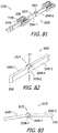
- the joint members 209f-1 and 209f-2 in the illustrated embodiment are cylindrical and C-shaped, respectively, and allow the first and second rods 206f-1 and 206e-2 to pivot relative to one another about an axis A1 from, for example, the rod positions illustrated in FIGS. 81-82 to, for example, the rod positions illustrated in FIG. 83 .
- the axis A1 is offset from axis A ( FIG. 78 ) by 90 degrees.
- One exemplary use of the contact array assembly 200f is the formation of an electrode array of the type described below with reference to FIG. 84 .
- jointed links may be ball and socket joints, or simply weak points formed in the rods 206-1 of the links 203b-1 ( FIGS. 32 and 34 ), to facilitate movement in multiple directions.
- all of the links in some contact array assemblies may be jointed.
- the present cochlear leads with pre-set curvatures are not limited to curves that define a flat plane.
- the present cochlear leads include cochlear leads with pre-set generally helical shape.
- One example of a mold that may be used to produce such is the mold 400d illustrated in FIGS. 84 and 85 .
- the mold 400d is similar to mold 400c and similar elements are represented by similar reference numerals.
- the mold 400d includes mold parts 402d-406d.
- the mold part 402d includes a block 408d with straight and curved portions 410d and 412d.
- a semi-circular lead defining surface 414d is formed in the straight and curved portions 410d and 412d of the block 408d.
- the lead defining surface 414d includes at least one bend point 415d where the lead defining surface is redirected by an angle ⁇ .
- the lead defining surface portion 418d will, therefore, extend helically around the curved portion 412d of the block 408d.
- a semi-circular surface 420d with a shape corresponding to a portion of the wing 128 is also formed in the straight portion 410d.
- a resilient insert (not shown) similar to the insert 412 described above with reference to FIGS.
- the mold parts 404d and 406d respectively include blocks 422c and 424c with semi-circular lead defining surfaces (not shown) which are coextensive with the lead defining surface 414d and, together with the lead defining surface 414d, define the mold cavity that is used to form a flexible body with a helical portion.
- the mold part 404d also includes a semi-circular surface (not shown) with a shape corresponding to a portion of the wing.
- contact array assembly 200d One example of a contact array assembly that may be inserted into the mold 400d and used to form a cochlear lead with pre-set generally helical shape is the contact array assembly 200d, as shown.
- Contact array assemblies with various combinations of the links 203b, the link 203e and/or the link 203f may also be employed.
- manufacture of the present contact array assemblies involves positioning the ends of a plurality of lead wires adjacent to the associated electrically conductive contacts or the workpieces that are used to form the contacts.
- the efficiency of this aspect of the manufacturing process may be improved through the use of wire holders that position the ends of the lead wires adjacent to the associated contacts or workpieces in such a manner that the ends of the lead wires may be readily pulled from the holder and positioned at the intended location.
- FIGS. 86-88 One example of a fixture with such a wire holder is the exemplary fixture 300d illustrated in FIGS. 86-88 .
- the fixture 300d is substantially similar to fixture 300c and similar elements are represented by similar reference numerals.
- the fixture 300d includes the aforementioned plate 302c with a top surface 304c, an elongate cavity 306c, and a plurality of markers 308c.
- the wire rest 310c has been omitted and replaced by a wire holder 310d.
- the exemplary wire holder 310d which includes a tubular member 322d and a horizontal slot 324d that extends through the tubular member, may be secured to the top surface 304c of the plate 302c or simply held in place by the technician.
- suitable materials for the tubular member 322d include silicone elastomers such as Silastic® silicone elastomer from Dow Corning.
- the lead wires 134 may be positioned with the tubular member 322d in such a manner that the ends extend through the slot 324d at locations corresponding to the contacts. Such an arrangement allows portions of the lead wires 134 to be pulled through the slot 324d as needed (e.g., just prior to the compression of a workpiece). The remainders of the lead wires 134 may continue to be held by the holder 310d until all of the wires have been connected to contacts.
- the holder 310d may be used to keep the wires out of the cavity 306c while resilient material is injected into the cavity in a manner similar to that described above in the context of the wire rest 310c and the contact array assembly 202c. The remainder of the lead wires 134 may then be pulled through the slot 324d and the holder 310d discarded or reused.
- the wire holder 310e includes a tubular member 322e with a horizontal slot 324e that extends through the tubular member.
- Vertical slots 324e which facilitate accurate placement of the wire ends relative to the plate 302c, as well as relative to the contacts or workpieces on the plate, also extend through the tubular member 322e.
- the exemplary fixture 300f includes a wire holder 310f with a tubular member 322f and a plurality of spaced apertures 324e through which the respective plurality of lead wire ends extend.
- the tubular member 322f, with the lead wires extending therethrough, may form part of the associated electrode array.
Landscapes
- Health & Medical Sciences (AREA)
- Life Sciences & Earth Sciences (AREA)
- Public Health (AREA)
- Veterinary Medicine (AREA)
- Engineering & Computer Science (AREA)
- Biomedical Technology (AREA)
- Nuclear Medicine, Radiotherapy & Molecular Imaging (AREA)
- Otolaryngology (AREA)
- Animal Behavior & Ethology (AREA)
- Radiology & Medical Imaging (AREA)
- General Health & Medical Sciences (AREA)
- Cardiology (AREA)
- Heart & Thoracic Surgery (AREA)
- Electrotherapy Devices (AREA)
- Eyeglasses (AREA)
- Prostheses (AREA)
Description
- The present disclosure relates generally to the implantable portion of implantable cochlear stimulation (or "ICS") systems and, in particular, to electrode arrays.
- ICS systems are used to help the profoundly deaf perceive a sensation of sound by directly exciting the intact auditory nerve with controlled impulses of electrical current. Ambient sound pressure waves are picked up by an externally worn microphone and converted to electrical signals. The electrical signals, in turn, are processed by a sound processor, converted to a pulse sequence having varying pulse widths, rates, and/or amplitudes, and transmitted to an implanted receiver circuit of the ICS system. The implanted receiver circuit is connected to an implantable lead with an electrode array that is inserted into the cochlea of the inner ear, and electrical stimulation current is applied to varying electrode combinations to create a perception of sound. The electrode array may, alternatively, be directly inserted into the cochlear nerve without residing in the cochlea. A representative ICS system is disclosed in
U.S. Patent No. 5,824,022 , which is entitled "Cochlear Stimulation System Employing Behind-The-Ear Sound processor With Remote Control". Examples of commercially available ICS sound processors include, but are not limited to, the Harmony™ BTE sound processor, the Naida™ CI Q Series sound processor and the Neptune™ body worn sound processor, which are available from Advanced Bionics. - As alluded to above, some ICS systems include an implantable cochlear stimulator (or "cochlear implant") having a lead with an electrode array, a sound processor unit (e.g., a body worn processor or behind-the-ear processor) that communicates with the cochlear implant, and a microphone that is part of, or is in communication with, the sound processor unit. The cochlear implant electrode array, which is formed by a molding process, includes a flexible body formed from a resilient material such as liquid silicone rubber ("LSR") and a plurality of electrically conductive contacts (e.g., sixteen platinum contacts) spaced along a surface of the flexible body. The contacts of the array are connected to lead wires that extend through the flexible body. Once implanted, the contacts face the modiolus within the cochlea.
- The present inventors have determined that conventional methods of manufacturing electrode arrays are susceptive to improvement. The electrically conductive contacts, which must have a clean exposed surface to function properly, are masked during the molding process to prevent the LSR or other resilient material from covering the contacts. In some conventional processes, the contacts are welded to an iron strip and the lead wires are welded to the contacts while they are supported on iron strip. The iron strip masks portions of the contacts. The contacts, iron strip and lead wires are then placed into a mold that is configured to accommodate the iron strip. Resilient material is injected into the mold to form the flexible body of the electrode array through an overmolding process. The electrode array is removed from the mold once the resilient material has cured. The iron strip is then etched away from the contacts, in a bath of nitric acid or hydrochloric acid, thereby exposing the contacts. The contacts must be cleaned after the acid bath. The acid bath and cleaning take approximately 8 hours. The present inventors have determined that it would be desirable to avoid the use of harsh chemicals and the production delay associated therewith. The present inventors have also determined that welded masks can result in an uneven and uncontrolled contact surface, with small granulations in surface structure, which is more likely to experience biofilm and fibrous tissue growth than a smooth surface. Irregular surfaces are also likely to result in electrical impedances that vary from contact to contact. Exemplary methods of manufacturing electrode arrays are disclosed in
U.S. Pat. Pub. No. 2011/0016710 . - The present inventors have also determined that conventional electrode arrays are susceptive to improvement. For example, conventional electrode arrays can buckle during the insertion process, which necessitates repositioning and can result in damage to any still functioning hair cells in the cochlea that allow residual hearing to occur. In particular, when a thin electrode array (e.g., diameter of about 0.33 mm) that is configured for placement against the lateral wall is inserted into an opening in the cochlea, such as an opening formed by the "round window" technique or a cochleostomy, the base portions of thin electrode arrays sometimes buckle mid-way through the insertion procedure. Exemplary methods of stiffening electrode arrays are disclosed in
U.S. Pat. Nos. 8,249,724 ,8,812,121 ,8,880,193 ,9,033,869 9,037,267 9,492,654 U.S. Pat. Pub. No. 2011/0137393 . - The present inventors have determined that conventional methods of making electrode arrays are susceptive to improvement. For example, some conventional methods involve the use of electrode array assemblies that include a plurality of conductive contacts which are respectively connected to a plurality of lead wires. A carrier (or "bridge" formed from a silicone adhesive is then applied to the contacts and lead wires prior to the remainder of the electrode array being molded onto the assembly. One example of a method that involves the use of such a bridge is disclosed in
U.S. Pat. Pub. No. 2011/0016710 . The present inventors have determined that placing the electrode array subassembly in a curved mold to form the carrier over lead wires can cause the lead wires to break. - The invention relates to a method of forming a cochlear implant electrode array as defined in
claim 1. - A contact array assembly for use during the manufacture of a cochlear implant electrode array in accordance with the present invention includes at least one carrier and a plurality of electrically conductive contacts, which are sized and shaped for insertion into the cochlea, removably mounted on the at least one carrier.
- There are a number of advantages associated with such methods and apparatus. For example, removing some or all of the carrier prior to molding eliminates the need for the post-molding etching processes associated with some conventional methods. Also, because the carrier is not associated with (and not in contact with) the tissue contact surfaces of the contacts, the present method and apparatus produce a smooth, clean surface that is less likely to experience biofilm and fibrous tissue grown after implantation or electrical impedances that vary from contact to contact. Keeping the lead wires out of the cavity in which the carrier is formed prevents the carrier from being formed over the lead wires. As a result, the lead wires will be free to move relative the remainder of the electrode array assembly when the electrode array assembly is placed in a curved mold, thereby reducing the likelihood that the lead wires will break.
- The above described and many other features of the present inventions will become apparent as the inventions become better understood by reference to the following detailed description when considered in conjunction with the accompanying drawings.
- Detailed descriptions of the exemplary embodiments will be made with reference to the accompanying drawings.
-
FIG. 1 is a plan view of a cochlear implant in accordance with one embodiment of a present invention. -
FIG. 2 is a perspective view of a portion of the cochlear lead illustrated inFIG. 1 . -
FIG. 3 is a perspective view of a portion of the cochlear lead illustrated inFIG. 1 . -
FIG. 4 is a section view taken along line 4-4 inFIG. 2 . -
FIG. 5 is a section view taken along line 5-5 inFIG. 2 . -
FIG. 6 is a section view taken along line 6-6 inFIG. 2 . -
FIG. 7 is a section view taken along line 7-7 inFIG. 2 . -
FIG. 8 is a perspective view of a contact array assembly in accordance with one embodiment of the present invention. -
FIG. 9 is another perspective view of the contact array assembly illustrated inFIG. 8 . -
FIG. 10 is a perspective view of a portion of the contact array assembly illustrated inFIG. 8 . -
FIG. 11 is a perspective view of one of the contacts in the contact array assembly illustrated inFIG. 8 . -
FIG. 12 is an end view of the contact illustrated inFIG. 11 . -
FIG. 13 is a perspective view of a portion of the contact array assembly illustrated inFIG. 8 . -
FIG. 14 is a perspective view of one of the contacts in the contact array assembly illustrated inFIG. 8 . -
FIG. 15 is an end view of the contact illustrated inFIG. 14 . -
FIG. 16 is a perspective view of a portion of the contact array assembly illustrated inFIG. 8 . -
FIG. 17 is a perspective view of one of the contacts in the contact array assembly illustrated inFIG. 8 . -
FIG. 18 is an end view of the contact illustrated inFIG. 17 . -
FIG. 19 is a plan view of the contact array assembly illustrated inFIG. 8 on a wire bonding fixture. -
FIG. 20 is a section view taken along line 20-20 inFIG. 19 . -
FIG. 21 is a plan view of the contact array assembly illustrated inFIG. 19 with wires bonded thereto. -
FIG. 22 is a plan view of a mold in accordance with one embodiment of a present invention. -
FIG. 23 is an exploded section view taken along line 23-23 inFIG. 22 . -
FIG. 24 is a plan view of the contact array assembly illustrated inFIG. 8 on a portion of the mold illustrated inFIGS. 22 and 23 with wires bonded thereto. -
FIG. 25 is a section view showing a portion of the contact array assembly illustrated inFIG. 8 on a portion of the mold illustrated inFIGS. 22 and 23 with wires bonded thereto. -
FIG. 26 is a section view showing a portion of the contact array assembly illustrated inFIG. 8 on a portion of the mold illustrated inFIGS. 22 and 23 with wires bonded thereto. -
FIG. 27 is a section view showing a portion of the contact array assembly illustrated inFIG. 8 in a mold with wires bonded thereto. -
FIG. 28 is a side view of a portion of the cochlear lead in accordance with one embodiment of a present invention. -
FIG. 29 is a plan view of a portion of a contact array assembly in accordance with one embodiment of the present invention. -
FIG. 30 is a plan view of the contact array assembly illustrated inFIG. 29 on a portion of the mold illustrated inFIGS. 22 and 23 with wires bonded thereto. -
FIG. 31 is a side view of a portion of cochlear lead in accordance with one embodiment of a present invention. -
FIG. 32 is a perspective view of a contact array assembly in accordance with one embodiment of the present invention. -
FIG. 33 is an exploded perspective view of a portion of the contact array assembly illustrated inFIG. 32 . -
FIG. 34 is a perspective view of a portion of the contact array assembly illustrated inFIG. 32 . -
FIG. 35 is a plan view of one of the contacts in the contact array assembly illustrated inFIG. 32 . -
FIG. 36 is a side view of the contact illustrated inFIG. 35 . -
FIG. 37 is an end view of the contact illustrated inFIG. 35 . -
FIG. 38 is a perspective view of the contact illustrated inFIG. 35 . -
FIG. 39 is a plan view of the contact array assembly illustrated inFIG. 35 on a wire bonding fixture. -
FIG. 40 is a plan view of a portion of the contact array assembly illustrated inFIG. 32 on the wire bonding fixture illustrated inFIG. 39 . -
FIG. 41 is a perspective view of a portion of the contact array assembly illustrated inFIG. 32 on the wire bonding fixture illustrated inFIG. 39 . -
FIG. 42 is a plan, cutaway view of the contact array assembly illustrated inFIG. 32 in a mold with wires bonded thereto. -
FIG. 43 is a section view taken along line 43-43 inFIG. 42 . -
FIG. 44 is a section view taken along line 44-44 inFIG. 42 . -
FIG. 45 is a section view taken along line 45-45 inFIG. 31 . -
FIG. 46 is a section view taken along line 46-46 inFIG. 31 . -
FIG. 47 is a perspective view of a portion of a cochlear lead in accordance with one embodiment of a present invention. -
FIG. 48 is a section view taken along line 48-48 inFIG. 47 . -
FIG. 49 is a section view of a portion of a cochlear lead in accordance with one embodiment of a present invention. -
FIG. 50 is a plan view of a contact array assembly in accordance with one embodiment of the present invention. -
FIG. 51 is a side view of the contact array assembly illustrated inFIG. 50 . -
FIG. 52 is a section view taken along line 52-52 inFIG. 50 . -
FIG. 53 is a section view taken along line 53-53 inFIG. 50 . -
FIG. 54 is a plan view of a portion of an exemplary method of manufacturing the contact array assembly illustrated inFIG. 50 in accordance with one embodiment of a present invention. -
FIG. 55 is a section view of a portion of the exemplary method of manufacturing the contact array assembly illustrated inFIG. 50 . -
FIG. 56 is a partial section view of a portion of the exemplary method of manufacturing the contact array assembly illustrated inFIG. 50 . -
FIG. 57 is a plan view of a portion of the exemplary method of manufacturing the contact array assembly illustrated inFIG. 50 . -
FIG. 58 is a section view of a portion of the exemplary method of manufacturing the contact array assembly illustrated inFIG. 50 . -
FIG. 59 is a partial section view of a portion of the exemplary method of manufacturing the contact array assembly illustrated inFIG. 50 . -
FIG. 60 is a plan view of a portion of the exemplary method of manufacturing the contact array assembly illustrated inFIG. 50 . -
FIG. 61 is an end view of a portion of the exemplary method of manufacturing the contact array assembly illustrated inFIG. 50 . -
FIG. 62 is a plan view of a portion of the exemplary method of manufacturing the contact array assembly illustrated inFIG. 50 . -
FIG. 63 is a plan view of a portion of the exemplary method of manufacturing the contact array assembly illustrated inFIG. 50 . -
FIG. 64 is a section view of a portion of the exemplary method of manufacturing the contact array assembly illustrated inFIG. 50 . -
FIG. 65 is a section view of a portion of the exemplary method of manufacturing the contact array assembly illustrated inFIG. 50 . -
FIG. 66 is a section view of a portion of the exemplary method of manufacturing the contact array assembly illustrated inFIG. 50 . -
FIG. 67 is a perspective view of a mold in accordance with one embodiment of a present invention. -
FIG. 68 is a perspective view of a portion of the mold illustrated inFIG. 67 . -
FIG. 69 is a perspective view of a portion of the mold illustrated inFIG. 67 . -
FIG. 70 is a plan view of the contact array assembly illustrated inFIG. 50 on a portion of the mold illustrated inFIG. 67 . -
FIG. 71 is a section view of the contact array assembly illustrated inFIG. 50 within the mold illustrated inFIG. 67 . -
FIG. 72 is a section view of the contact array assembly illustrated inFIG. 50 within the mold illustrated inFIG. 67 . -
FIG. 73 is a side view of a contact array assembly in accordance with one embodiment of the present invention. -
FIG. 74 is a section view of a portion of an exemplary method of manufacturing the contact array assembly illustrated inFIG. 73 in accordance with one embodiment of a present invention. -
FIG. 75 is a section view taken along line 75-75 inFIG. 73 . -
FIG. 75A is a section view of a portion of an exemplary method of manufacturing a contact array assembly in accordance with one embodiment of a present invention. -
FIG. 76 is a side view of a portion of cochlear lead in accordance with one embodiment of a present invention. -
FIG. 77 is a perspective view of a contact array assembly in accordance with one embodiment of the present invention. -
FIG. 78 is a perspective view of a portion of the contact array assembly illustrated inFIG. 77 . -
FIG. 79 is a side view of a portion of the contact array assembly illustrated inFIG. 77 . -
FIG. 80 is a side view of a portion of the contact array assembly illustrated inFIG. 77 . -
FIG. 81 is a perspective view of a portion of a contact array assembly in accordance with one embodiment of the present invention. -
FIG. 82 is a perspective view of a portion of the contact array assembly illustrated inFIG. 81 . -
FIG. 83 is a top view of a portion of the contact array assembly illustrated inFIG. 81 . -
FIG. 84 is a perspective view of a mold in accordance with one embodiment of a present invention. -
FIG. 85 is a plan view of the contact array assembly illustrated inFIG. 50 on a portion of the mold illustrated inFIG. 84 . -
FIG. 86 is a plan view of a fixture in accordance with one embodiment of a present invention. -
FIG. 87 is a side view the fixture illustrated inFIG. 86 . -
FIG. 88 is a section view taken along line 88-88 inFIG. 87 . -
FIG. 89 is a side view of a fixture in accordance with one embodiment of a present invention. -
FIG. 90 is a side view of a fixture in accordance with one embodiment of a present invention. - The following is a detailed description of the best presently known modes of carrying out the inventions. This description is not to be taken in a limiting sense, but is made merely for the purpose of illustrating the general principles of the inventions.
- One example of a cochlear implant (or "implantable cochlear stimulator") in accordance with at least some of the present inventions is illustrated in
FIGS. 1-7 . Thecochlear implant 100 includes aflexible housing 102 formed from a silicone elastomer or other suitable material, aprocessor assembly 104, acochlear lead 106 with anelectrode array 108, and anantenna 110 that may be used to receive data and power by way of an external antenna that is associated with, for example, a sound processor unit. Theelectrode array 108 includes aflexible body 112 and a plurality of electrically conductive contacts 114 (e.g., the sixteencontacts 114 illustrated inFIG. 2 ) spaced along thecurved bottom surface 116 of the flexible body between thetip 118 and thebase 120. Apositioning magnet 122 is located within amagnet pocket 124. Themagnet 122 is used to maintain the position of a headpiece transmitter over theantenna 110. The cochlear implant may, in some instances, be configured is manner that facilitates magnet removal and replacement. Here, thehousing 102 may be provided with a magnet aperture (not shown) that extends from themagnet pocket 124 to the exterior of the housing. - Suitable materials for the
flexible body 112 include, but are not limited to, LSR, high temperature vulcanization ("HTV") silicone rubbers, room temperature vulcanization ("RTV") silicone rubbers, and thermoplastic elastomers ("TPEs"). Thecontacts 114 may be referred to in numbered order, 1st through 16th, with the contact closest to thetip 118 being the 1st contact and the contact closest to the base 120 being the 16th contact. The exemplaryflexible body 112 also includes a longitudinally extending curvedtop surface 126 that does not include conductive contacts. Once implanted, theconductive contacts 114 on thecurved surface 116 face the modiolus within the cochlea. The exemplaryflexible body 112 has a circular shape in a cross-section perpendicular to the longitudinal axis LA of the electrode array 108 (FIGS. 4-7 ). In other implementations, a truncated circular shape, with a flat top surface, or an oval shape, with or without truncation, or any other suitable shape, may be employed. It should also be noted that the methods of forming the electrode array described below produce smooth exterior surface transitions from theflexible body 112 to thecontacts 114. - Referring more specifically to
FIG. 2 , in addition to theelectrode array 108, the exemplarycochlear lead 106 includes awing 128, with arectangular portion 130 and atapered portion 132, which functions as a handle for the surgeon during the implantation surgery. Thewing 128 also provides tension relief for lead wires 134 (FIG. 4 ), which do not run straight through the wing. Atubular member 136, which may consist of tubes of different sizes, extends from thewing 128 to thehousing 102. Thecontacts 114 are connected to thelead wires 134 that extend through theflexible body 112 andtubular member 136 to a connector (not shown) in thehousing 102. - The
exemplary electrode array 108 has a tapered shape, with a diameter that is larger at the base 120 than at thetip 118, and includescontacts 114 of different sizes and shapes. In the illustrated embodiment, there are three different contact configurations, i.e., contacts 114-1, 114-2 and 114-3, andreference numeral 114 is used herein to refer to all of the contacts generically. Contacts 114-1 (and the associated portion of the flexible body 112) are larger than contacts 114-2 (and the associated portion of the flexible body), and contacts 114-2 (and the associated portion of the flexible body) are larger than contacts 114-3 (and the associated portion of the flexible body). - As illustrated in
FIG. 5 and10-12 , the exemplary contacts 114-1 include asolid body 138, a curvedtissue contact surface 140, side surfaces 142 withouter edges 144, and a flatwire contact surface 146. One or more apertures 148 (two cylindrical apertures in the illustrated implementation) extend through thesolid body 138. Theapertures 148 are located inward of, and are offset from, thetissue contact surface 140. Prior to the molding process, theapertures 148 support the contacts 114-1 oncarrier rods 202, as is discussed below with reference toFIGS. 8 and 9 . Thecarrier rods 202 are removed prior to the molding process used in the formation of theelectrode array 108. As a result, portions of theflexible body 112 are located within theapertures 148, thereby interlocking the contacts 114-1 with the flexible body. As discussed below with reference toFIGS. 19-21 , one of thewires 134 is connected to thewire contact surface 146 at a bond 134'. Turning toFIG. 6 and13-15 , the exemplary contacts 114-2 include asolid body 150, a curvedtissue contact surface 152, and a flatwire contact surface 154 withouter edges 156. One or more apertures 148 (two in the illustrated implementation) extend through thesolid body 150. Theapertures 148 are located inward of, and are offset from, thetissue contact surface 152. One of thewires 134 is connected to thewire contact surface 146 at a bond 134'. The exemplary contacts 114-3 (FIG. 7 and16-18 ) include asolid body 158, a curvedtissue contact surface 160, side surfaces 162 withouter edges 164, and a flatwire contact surface 166. One or more apertures 148 (two in the illustrated implementation) extend through thesolid body 158. Theapertures 148 are located inward of, and are offset from, thetissue contact surface 160. One of thewires 134 is connected to thewire contact surface 166 at a bond 134'. - Suitable conductive materials for the
contacts 114 include, but are not limited to, platinum, platinum-iridium, gold and palladium. Theexemplary contacts 114 may be solid (as shown) or a PEEK or ceramic structure that is coated or plated with the conductive material. With respect to dimensions, theexemplary contacts 114 are sized and shaped for insertion into the cochlea and have widths (measured horizontally inFIGS. 5-7 ) that range from 0.35 mm to 0.5 mm, and radii that range from 0.17 mm to 0.25 mm. Theexemplary apertures 148 are circular in cross-section with diameters that range from 0.1 mm to 0.15 mm. The distance betweenadjacent contacts 114 may range from 0.5 mm to 1.5 mm, and the distance may be constant or variable. It should also be noted that thecontacts 114 have the same configuration before and after being placed onto the carrier rods 202 (discussed below). - Contacts such as
contacts 114 may form part of a contact array assembly that is used during the formation of an electrode array. In the exemplarycontact array assembly 200 illustrated inFIGS. 8 and 9 , which is used in the formation of theelectrode array 108, all three types of contacts 114 (i.e., contacts 114-1, 114-2 and 114-3) are positioned oncarrier rods 202 that extend through thecontact apertures 148. Thecarrier rods 202 are located inward of, and are offset from, the tissue contact surfaces 140, 152 and 160 of the contacts 114-1, 114-2 and 114-3. A slip fit, a line to line fit, or a slight friction fit between thecontacts 114 and thecarrier rods 202 allows the carrier rods to be separated from the contacts at the appropriate time (e.g., after the contact array assembly has been placed in a mold) without destroying the carrier rods and/or the contacts or altering the spacing between adjacent contacts. In some instances, instead of a slight friction fit, a small amount of medical grade adhesive may be used to fix the positions of thecontacts 114 on thecarrier rods 202 with bonds that are weak enough to allow the carrier rods to be separated from the contacts. Put another way, in the illustrated implementation, thecarrier rods 202 are removably inserted intoapertures 148 of thecontacts 114. - The
exemplary carrier rods 202 are malleable, which allows thecontact array assembly 200 to be bent in order to conform to curved molds that produce pre-curved electrode arrays. Suitable structures for thecarrier rods 202 include, but are not limited to, stainless steel rods (e.g., gauge pins) with a diameter of 0.1 mm to 0.15 mm. In other implementations, the carrier rods may be resilient (i.e., will bend and then return to their original shape when the bending force is removed), super-elastic, or rigid. In other implementations, such as that described below with reference toFIGS. 28-30 , thecarrier rods 202 may be formed from electrically non-conductive material such as PEEK, PTFE or polyester, as well as the shape memory materials described below. - It should also be noted here that the present contact array assemblies are not limited to the
exemplary assembly 200. For example, other implementations may include fewer than (or more than) sixteen contacts and/or contacts that all have the same configuration. Other exemplary contact array assemblies are described below with reference toFIGS. 31-75 . - As illustrated for example in
FIGS. 19 and 20 , thecontact array assembly 200 may be positioned on awire bonding fixture 300 that holds the contact array assembly while thelead wires 134 are being bonded to theindividual contacts 114. Theexemplary bonding fixture 300 includes amain body 302 and achannel 304 that is sized and shaped to accommodate thecontacts 114. Individual pockets (not shown) or other suitable structures may be provided within thechannel 304 to insure that theelectrodes 114 are properly spaced. After thecontact array assembly 200 has been positioned on thewire bonding fixture 300, each lead wire 134 (sixteen in the illustrated implementation) may be physically bonded and electrically connected to a respective one of the wire contact surfaces 146, 154 and 166 of the contacts 114-1, 114-2 and 114-3 in the manner illustrated inFIG. 21 (where only three lead wires are shown for purposes of clarity). For example, the end portion of eachlead wire 134 may be stripped of insulation and bonded to the wire contact surface 146 (or 154 or 166) by resistance welding, wire bonding, hot bar welding, or any other suitable technique to form the bonds 134'. The bonds 134' may be created in series, starting with contact sixteen (i.e., the contact 114-1 that will be closest to the base 120) and ending with contact one (i.e. the contact 114-3 that will be closest to the tip 118), to prevent damage to thelead wires 134. The resulting lead wire bundle may be secured to the some or most of thecontacts 114 with medical grade adhesive. The stiffness of thelead wires 134 helps maintain proper spacing between thecontacts 114. - The
contact array assembly 200, withwires 134 attached thereto, may thereafter be transferred to a mold into which the LSR (or other resilient material) will be injected to form theflexible body 112. One example of such a mold is themold 400 illustrated inFIGS. 22-27 . Referring first toFIGS. 22 and 23 , theexemplary mold 400 includes first andsecond mold parts first mold part 402 includes aplate 406 with acontact surface 408 and anelongate cavity 410. Aresilient insert 412, which includes abody 414, a curvedlead defining surface 416 and top ends 418 that extend beyond thecontact surface 408 of the first mold part 402 (e.g., by 0.002 inch), may be positioned within theelongate cavity 410. Suitable materials for the resilient insert include, but are not limited to, urethane, silicone, or any other suitable compliant material. Thefirst mold part 402 and/or theresilient insert 412 may include verification indicia (not shown) so that, prior to molding, the spacing between thecontacts 114 can be verified and, if necessary, adjusted. Thesecond mold part 404 includes aplate 420 with acontact surface 422, a curvedlead defining surface 424 andedges 426 where the contact surface and channel intersect. After insertion of thecontact array assembly 200, and prior to injection of the LSR (or other resilient material), the first andsecond mold parts lead defining surface 416 aligned with thelead defining surface 424, which together define amold cavity 428 the shape of theflexible body 112. The top ends 418 are compressed to form a tight seal. - In the illustrated implementation, the
mold parts mold plates resilient insert 412 may be replaced as necessary. In other implementations, the mold may be a single-use device. - Turning to
FIG. 24 , thecontact array assembly 200, withwires 134 attached thereto, may be pressed into thelead defining surface 416 of theresilient insert 412 while the first andsecond mold parts insert 412 insures that there is a tight fit between thecontacts 114 and thelead defining surface 416. The masking effect of the tight fit prevents the LSR (or other resilient material) from flashing over the outer surfaces of thecontacts 114 during the injection molding process. The first andsecond mold parts surfaces 408 and 422 (FIG. 23 ) contacting one another and the mold part edges 426 engaging theedges FIGS. 5-7 ) of the contacts 114-1, 114-2 and 114-3 to press the tissue contact surfaces 140, 152, 160 against thelead defining surface 416. Thecarrier rods 202 may then be pulled out of thecontacts 114, which leaves theapertures 148 open in the manner illustrated inFIGS. 25-27 . A clamp, screws or other suitable instrumentality (not shown) may be used to hold themold parts contacts 114 and thelead defining surface 416 also prevents the contacts from moving when thecarrier rods 202 are pulled out. - It should also be noted that the wing 128 (
FIG. 2 ) may in some instances be formed with a mold (not shown) which has a wing-shaped cavity and is aligned with themold 400 during the injection process. - The LSR or other suitable resilient material may then be injected (or otherwise introduced) into the
mold cavity 428, both around thecontacts 114 and into theapertures 148, to form theflexible body 112. The masking effect of thelead defining surface 416 prevents the resilient material from flashing over the outer surfaces of thecontacts 114. The resilient material within the apertures 148 (FIGS. 5-7 ) creates a mechanical interlock between theflexible body 112 and thecontacts 114. After the resilient material hardens, themold parts electrode array 108 may be removed from theinsert 412 by, for example, simply pulling the completedflexible body 112 out of the insert. - There are some instances where it may be desirable to increase the stiffness of the electrode array in the region adjacent to the wing to, for example, prevent the electrode array from buckling during the insertion process. One example of a cochlear lead that includes such an increase in stiffness is the
cochlear lead 106a illustrated inFIGS. 28 and 29 . Thecochlear lead 106a is substantially similar to thecochlear lead 106 described above with reference toFIGS. 1-18 . For example, thecochlear lead 106a includes anelectrode array 108 with aflexible body 112 and a plurality of electrically conductive contacts 114 (e.g., the sixteencontacts 114 illustrated inFIG. 2 ) between the tip and the base 120 that are connected to lead wires in the manner described above. Awing 128, with arectangular portion 130 and atapered portion 132, is located at theelectrode array base 120. Thecochlear lead 106a may also be incorporated into thecochlear implant 100 in place of thelead 106. - Here, however, the
lead 106a also includes astiffener 170 that extends through a plurality of thecontacts 114, through thebase 120, and into thewing 128. Thestiffener 170 has afirst end 172 that is located within therectangular portion 130 of thewing 128 and asecond end 174 that is located within one of thecontacts 114. - In the illustrated implementation, the
stiffener 170 is formed fromportions 204 of thecarrier rods 202 in thecontact array assembly 200. Instead of pulling thecarrier rods 202 out of each of contacts 114-1, 114-2 and 114-3 when the electrode array assembly is on themold part 402, as is described above with reference toFIGS. 24-27 , the carrier rods are pulled until they only remain in thosecontacts 114 through which thestiffener 170 is intended to extend. Referring toFIG. 30 , once the ends of thecarrier rods 202 are aligned with only the intended contacts 114 (e.g., the four contacts 114-1 closest to the wing 128), the carrier rods may be cut or otherwise severed along a cut line CL to form the rod portions 204 (FIG. 29 ). The cut line CL may be located at the portion of thecarrier rods 202 that will define thefirst end 172 of thestiffener 170. Theflexible body 112 may then be molded onto thecontacts 114 in the manner described above. It should also be noted that therods 202 use to form thestiffener 170 are electrically non-conductive. - It should also be noted that in those instances where portions of the carrier rods are used to form a stiffener that remains in a contact array assembly, one rod or more than two rods may be employed, and cross-sectional shapes other than circular may be employed to provide desired bending characteristics. By way of example, by not limitations, one or more carrier rods with oval, rectangular, octagon, I-beam, or other shapes may be employed.
- Another exemplary cochlear lead that includes an increase in stiffness adjacent to the
wing 128 is thecochlear lead 106b illustrated inFIG. 31 . Thecochlear lead 106b is substantially similar to thecochlear lead 106a described above with reference toFIGS. 28-30 . Thecochlear lead 106b, which may also be incorporated into thecochlear implant 100 in place of thelead 106, includes anelectrode array 108b with aflexible body 112b and a plurality of electricallyconductive contacts 114b (e.g., the sixteencontacts 114b illustrated inFIG. 32 ) between thetip 118 and the base 120 that are connected to lead wires in the manner described below. Contact sixteen is closest to thebase 120 and contact one is closest to thetip 118. Awing 128, with arectangular portion 130 and atapered portion 132, is located at theelectrode array base 120. Astiffener 180 is associated with a plurality of thecontacts 114b that are adjacent to thebase 120. Thestiffener 180 also extends into thewing 128, and has afirst end 182 that is located within therectangular portion 130 of thewing 128 and asecond end 184 that is located within theflexible body 120. Thestiffener 180 may be formed from portions of acontact array assembly 200b (FIGS. 32-34 ) that is used in the manufacturing process. In some instances, the end portion of the base 120 may include areinforcement 114b' which, in the illustrated implementation, is an electrically conductive contact that is identical tocontacts 114b and is not connected to a lead wire. Other types of reinforcements may also be provided. - Turning to
FIGS. 32-34 , the exemplarycontact array assembly 200b includes the aforementioned plurality of electricallyconductive contacts 114b as well as acarrier 202b that is defined by a plurality of relatively stiff, electricallynon-conductive links 203b. As used herein, a relatively stiff link is a link that is formed from material that is stiffer than the LSR (or other resilient material) that is used to form theflexible body 112b. In the illustrated embodiment, there are three different link configurations, i.e., links 203b-1, 203b-2 and 203b-3, and reference numeral 203b is used herein to refer to all of the links generically. Thelinks 203b-1, 203b-2 and 203b-3 include respective rods 206-1, 206-2 and 206-3 as well asconnectors 208 located at the longitudinal ends of the rods. Theconnectors 208 are configured to engage with, and disengage from, correspondingconnectors 148b on thecontacts 114b when thelinks 203b are moved in the directions of arrows A and B (FIG. 33 ). Theconnectors 208 will not, however, disengage from the correspondingconnectors 148b when thecontacts 114b are moved in the direction of arrow C. Some of thelinks 203b will be removed from theassembly 200b prior to the molding of theflexible body 112b as is described below. Thelinks 203b are identical to one another but for the length of the rods 206-1, 206-2 and 206-3 in the illustrated implementation, but may be different in other implementations. The length of the rods 206-1 corresponds to the distance betweenadjacent contacts 114b. The length of the rod 206-2, which is greater than the length of the rods 206-1, corresponds to the distance between thebasal-most contact 114 and thereinforcement 114b'. The length of the rod 206-3, which is greater than the length of the rod 206-2, corresponds to the distance that thestiffener 180 extends into thewing 128. - The relatively stiff, electrically
non-conductive links 203b may be formed from material that is 1 to 1000% stiffer than the material used to form theflexible body 112. Suitable materials for thelinks 203b include, but are not limited to high durometer LSR, PEEK, PTFE and polyester. Shape memory materials may also be employed. For example, the links may straight at room temperature (about 22C) and curved at body temperature (about 37C). Suitable shape memory materials include shape memory metals such as Nitinol (with an electrically non-conductive coating such as PTFE or parylene) and shape memory polymers such as polyethylene glycol (PEG). The shape memory links may be used to, for example, create an electrode array that conforms to the shape of the cochlea in a manner similar to a pre-curved electrode array. Such an electrode array provides certain advantages associated with pre-curved electrode arrays that are molded in a curved state, e.g., the ability to position some or all contacts closer to the modiolus, which can be useful in preventing cross-stimulation that occurs when two contacts stimulate the same part of modiolus, without sacrificing certain advantages associated with electrode arrays that are molded in a straight state, e.g., a relatively simple molding process. - The cross-sectional shape of the rods 206-1, 206-2 and 206-3 may be rectangular, as shown. Other cross-sectional shapes, such as I-beam, circular, oval, or hexagon, may be employed to provide different bending characteristics. The
connectors 208 are cylindrical, with a diameter larger than the width of the associated rod, in the illustrated implementation so as to correspond to the shape of thecontact connectors 148b. Other shapes may also be employed. - Referring to
FIGS. 35-38 , the exemplary electricallyconductive contacts 114b include asolid body 138b, a curvedtissue contact surface 140b, side surfaces 142b withouter edges 144b, and awire contact surface 146b. Theconnectors 148b are located inward of, and are offset from, thetissue contact surface 140b (as shown). As a result, thelinks 203b are also located inward of, and are offset from, thetissue contact surface 140b. Theconnectors 148b also have configurations which correspond to those of theconnectors 208. To that end, theexemplary connectors 148b include aslot 150b having a relativelynarrow portion 152b and a relativelywide portion 154b. The relativelynarrow portion 152b has a rectangular shape while the relativelywide portion 154b has a circular shape. Other connector configurations that allow thecontacts 114b andlinks 203b to be selectively connected and disconnected in the manner described above may be employed. - The respective configurations of the
connectors carrier 202b (e.g., some of thelinks 203b-1) to be separated from thecontacts 114b at the appropriate time (e.g., after the contact array assembly has been placed in a mold) without destroying the links and/or the contacts or altering the spacing between adjacent contacts. Put another way, in the illustrated implementation, thelinks 203b-1 are removably secured to thecontacts 114b. - The
exemplary contacts 114b may also be provided with various features that facilitate connection to a lead wire in the manner described below with reference toFIGS 40 and 41 . In the illustrated embodiment, thecontacts 114b include a pair ofslots 156b that extend from one longitudinal end to the other on opposite sides of theconnectors 148b as well as a pair ofindentations 158b between the slots and thewire contact surface 146b. - The
exemplary contacts 114b may be formed from the conductive materials described above in the context ofcontacts 114, i.e., materials such as platinum, platinum-iridium, gold and palladium. Suitable manufacturing processes include, but are not limited to, 3-dimensional photo-etching processes such as #D printing, selective laser sintering (SLS), LIGA lithography, electroplating and metal injection molding (MIM) processes. The size and spacing of thecontacts 114b may be the same thecontacts 114. Thecontacts 114b may all be the same size (as shown) or may vary in size in those instances where theelectrode array 108b has a tapered shape, with an array diameter that is larger at the base 120 than at thetip 118. - As illustrated for example in
FIG. 39 , thecontact array assembly 200b may be positioned on awire bonding fixture 300b, which holds the contact array assembly while thelead wires 134 are being bonded to theindividual contacts 114b. Theexemplary bonding fixture 300b includes amain body 302 and achannel 304b that is sized and shaped to accommodate thecontacts 114b. Proper spacing of thecontacts 114b is maintained by thecarrier 202b and, in particular, by thelinks 203b. After thecontact array assembly 200b has been positioned on thewire bonding fixture 300, each lead wire 134 (sixteen in the illustrated implementation) may be physically bonded and electrically connected to a respective one of the wire contact surfaces 146b in the manner illustrated inFIGS. 40 and 41 . For example, the end portion of eachlead wire 134 may be stripped of insulation and fed through one of theslots 156b of acontact 114b and then redirected onto thewire contact surface 146b. The end portion of eachlead wire 134 may then be bonded to thewire contact surface 146b by resistance welding, wire bonding, hot bar welding, or any other suitable technique to form the bonds 134'. The bonds 134' may be created in series, starting with contact sixteen (i.e., thecontact 114b that will be closest to the base 120) and ending with contact one (i.e. thecontact 114b that will be closest to the tip 118), to prevent damage to thelead wires 134. In some instances, the choice ofslot 156b may alternate from onecontact 114b to the next and, accordingly, eightlead wires 134 will extend towards and past thereinforcement 114b' on one side of thelinks 203b and another eight lead wires will extend towards and past the reinforcement on the other side of the links. - The
contact array assembly 200b, withwires 134 attached thereto, may thereafter be transferred to a mold into which the LSR (or other resilient material) will be injected to form theflexible body 112b. One example of such a mold is themold 400b illustrated inFIGS. 42-44 . Themold 400b is substantially similar tomold 400 and similar elements are represented by similar reference numerals. For example, themold 400b includes first andsecond mold parts first mold part 402 includes aplate 406 with acontact surface 408, anelongate cavity 410, and aresilient insert 412b with alead defining surface 416b that is configured to accommodate thecontacts 114b. Thesecond mold part 404 includes aplate 420 with acontact surface 422 and a curvedlead defining surface 424b. The first andsecond mold parts lead defining surface 416b aligned with thelead defining surface 424b, which together define amold cavity 428b the shape of theflexible body 112b. - During the molding process, the
contact array assembly 200b, withwires 134 attached thereto, may be pressed into thelead defining surface 416b of theresilient insert 412b while the first andsecond mold parts mold 400. Thelinks 203b will maintain the proper spacing between thecontacts 114b, as well as between thebasal-most contact 114b and thereinforcement 114b'. A portion of thecarrier 202b (i.e., some of thelinks 203b-1) that will not form part of thestiffener 180 may then be removed (FIG. 42 ) by simply moving the links in the direction of arrow B (FIG. 33 ), while the links that will form part of thestiffener 180 will remain attached to the associatedcontacts 114b. Thelead wires 134 may then be bundled in, for example, the manner illustrated inFIG. 43 . The first andsecond mold parts mold cavity 428b to form theflexible body 112b, as shown inFIGS. 45 and 46 . After the resilient material hardens, themold parts electrode array 108b may be removed from theinsert 412b by, for example, simply pulling the completedflexible body 112b out of the insert. - There are some instances where it may be desirable to pre-curve the cochlear lead. One example of a cochlear lead that includes a pre-set curvature is the
cochlear lead 106c illustrated inFIG. 47 . Thecochlear lead 106c is substantially similar to thecochlear lead 106 described above with reference toFIGS. 1-18 . For example, thecochlear lead 106c includes anelectrode array 108c with a curvedflexible body 112c and a plurality of electricallyconductive contacts 114c (e.g., sixteen contacts) between thetip 118 and the base 120 that are connected to leadwires 134. Awing 128c, with acylindrical portion 130c and atapered portion 132c, is located at theelectrode array base 120. Amarker contact 114c', which is not connected to a lead wire, is located adjacent to thebase 120. Thecochlear lead 106c may also be incorporated into thecochlear implant 100 in place of thelead 106. - The
exemplary electrode array 108c has a circular cross-section and the curved tissue contact surfaces 140c of thecontacts 114c extend about one-half of the way around (i.e., about 180 degrees around) the perimeter of the array. The contacts may, however, have tissue contact surfaces that extend more or less than one-half of the way around the perimeter in other implementations. For example, the electrode array 108cc illustrated inFIG. 49 is otherwise identical toelectrode array 108c and includes a plurality ofcontacts 114d on a curvedflexible body 112d. Thecontacts 114d have curved tissue contact surfaces 140d that extend more than one-half of the way around (i.e., more than 180 degrees around) the perimeter of the cross-section. - Contacts such as
contacts 114c andmarker 114c' may form part of a contact array assembly that is used during the formation of theexemplary electrode array 108c. Thecontacts 114c andmarker 114c' in the exemplarycontact array assembly 200c illustrated inFIGS. 50-53 are positioned on acarrier 202c. Thecontact array assembly 200c also includes thelead wires 134. Thecarrier 202c may be formed from the same material as, and ultimately becomes part of, theflexible body 112c. To that end, thecarrier 202c includes acurved bottom surface 210c, which will become part of thecurved bottom surface 116c of theflexible body 112c, and atop surface 212c. Thelead wires 134 are secured to the remainder of thecontact array assembly 200c in such a manner that the lead wires are less likely to break, as compared to conventional assemblies, when thecontact array assembly 200c is inserted into a curved mold. In particular, each of thelead wires 134 may be secured only to the associatedcontact 114c and positioned on top of thecarrier top surface 212c (as opposed to molding the lead wires into thecarrier 202c). As a result, when the straightcontact array assembly 200c is pressed into a curved mold in, for example, the manner described below with reference toFIGS. 70-72 , thelead wires 134 will be free to move relative to thecarrier 202c and will be less likely to break due to tension. - The exemplary
contact array assembly 200c may be formed in theexemplary fixture 300c illustrated inFIG. 54 in accordance with the method described below with reference toFIGS. 55-62 . Thefixture 300c includes aplate 302c with atop surface 304c and anelongate cavity 306c with a curvature corresponding to that of theelectrode array 108c. Thetop surface 304c includesmarkers 308c which correspond to the intended locations of thecontacts 114c. Here, there is asingle marker 308c for each of thecontacts 114c. In another implementation (not shown), a set of fourmarkers 308c (two on each side of thecavity 306c) may be provided for each of thecontacts 114c. Awire rest 310c extends upwardly from thetop surface 304c. - The
fixture 300c may in some instances be a disposable part formed by a photoetching process. Although iron and other photoetchable materials may be employed, thefixture 300c is formed from copper, which is relatively inexpensive and has a number of advantageous properties. Copper is unlikely to bond toplatinum contacts 114c because copper does not weld easily and has relatively high thermal conductivity, which causes heat to dissipate very readily. Copper is also resilient in that it will flex slightly and return to its shape when the platinum contact workpieces (discussed below) are pressed through the opening. Copper is easy to bend, which facilitates release of the electrode array (discussed below). Also, as copper is electrically conductive, it may be used in an opposed weld process where thecopper fixture 300c forms part of the electrical loop. In other implementations, thefixture 300c may be a reusable apparatus that consists of two separable pieces formed from a harder material such as stainless steel. - The exemplary method involves placing
contact workpieces 312c into thecavity 306c at locations corresponding to thecontacts 114c andmarker 114c', as well as placing one end of alead wire 134 into each workpiece in the case of thecontacts 114c, and then applying heat and pressure to the workpiece. Referring first toFIGS. 54 and 55 , theexemplary contact workpiece 312c is a tube defined by awall 314c formed from platinum or other suitable contact material. Although not limited to any particular shape, the exemplary workpiece is a cylindrical tube and is circular in cross-section. Theworkpiece 312c illustrated inFIGS. 54 and 55 will form themarker 114c'. The heat and pressure causes compression and distortion of themalleable workpiece 312c as shown inFIG. 56 . Portions of thewall 314c will come into contact with one another along aseam 318c. In some instances, gaps (not shown) may remain between some portions of the wall. The gaps augment the mechanical interconnection between thecarrier 202c and thecontacts 114c. - The heat and pressure may be applied with, for example, a weld tip, such as the
molybdenum weld tip 316c, in a resistance welding process. In other implementations, themarker 114c' andcontacts 114 may be formed by compressing theworkpiece 312c with a stainless steel weld tip (no heat applied) and then applying heat with a molybdenum weld tip, thereby preventing wear on both weld tips. - Turning to
FIGS. 57 and 58 , formation of thecontact 114c closest to themarker 114c' (as well as the other contacts) involves placing aworkpiece 312c into thecavity 306c and placing the end of thelead wire 134 into the workpiece. Heat and pressure may then be applied to theworkpiece 312c to form thecontact 114c, and bond the end of thelead wire 134 to the contact, in the manner illustrated inFIG. 59 . It should also be noted that themarker 114c' and contact 114 are pressed tightly against themold surface 320c that defines thecavity 306c, thereby preventing movement of the marker and contact and also masking the curved tissue contact surfaces 140c of the marker and contact. Themold surface 320c also defines a portion of the outer surface ofcarrier 202c in the spaces not covered by thecontacts 114c. - Turning to
FIGS. 60 and 61 , one end of the associatedlead wire 134 will be secured to the associatedcontact 114c, and therefore immovable relative to the contact, after the contact is formed. The remainder of thelead wire 134 may be moved out of thecavity 306c. As a result, the portion of thelead wire 134 that is coextensive with thecarrier 202c will not be molded into carrier. In the illustrated implementation, thelead wire 134 may be directed over thewire rest 310c. - The steps described above with reference to
FIGS. 57-61 may then be repeated to form the remainder to thecontacts 114c. Referring toFIGS. 62 and63 , after eachcontact 114c is formed by compressingworkpiece 312c onto the end of the associatedlead wire 134, the lead wires may be may be directed out of the cavity and over thewire rest 310c. - Once all of the
contacts 114c have been formed, and while thelead wires 134 remain outside of thecavity 306c, LSR or other suitable resilient material may then be injected (or otherwise introduced) into thecavity 306c as shown inFIG. 64 to form thecarrier 202c. After the resilient material has cured to such an extent that thelead wires 134 will not sink into it, the lead wires may be positioned on thetop surface 212c (FIG. 65 ) to complete thecontact array assembly 200c. Thecontact array assembly 200c may be removed from thefixture 300c by simply pulling the assembly out of thecavity 306c. Referring toFIG. 66 , bending of theplate 302c may be required in some instances when removing thecontact array assembly 200c from thecavity 306c. - The
contact array assembly 200c may then be placed into a mold to form the remainder of the curvedcochlear lead 106c. Referring toFIGS. 67-70 , one example of such a mold is themold 400c withmold parts 402c-406c. Themold part 402c includes ablock 408c with straight andcurved portions lead defining surface 414c, with straight andcurved portions curved portions block 408c. Asemi-circular surface 420c with a shape corresponding to a portion of thewing 128c is also formed in thestraight portion 410c. In some instances, a resilient insert (not shown) similar to theinsert 412 described above with reference toFIGS. 22-27 may be provided. Themold parts blocks lead defining surfaces FIGS. 71 and 72 ) which, together with thelead defining surface 414c, define themold cavity 428c (FIGS. 71 and 72 ) that is used to form theflexible body 112c. Themold part 404c also includes a semi-circular surface (not shown) with a shape corresponding to a portion of thewing 128c. - After insertion of the
contact array assembly 200c, and prior to injection of the LSR (or other resilient material), themold parts 402c-406c may be clamped together with thelead defining surfaces mold cavity 428c the shape of theflexible body 112c. The LSR or other suitable resilient material may then be injected (or otherwise introduced) into themold cavity 428c to form theflexible body 112c. After the resilient material hardens, themold parts 402c-406c may be separated from one another and the completedelectrode array 108c may be removed. - Some cochlear leads with pre-set curvatures are straightened prior to the insertion process by a stylet or other stiffening element that is inserted into a stylet lumen within the electrode array. The present contact array assemblies may be configured to provide such a stylet lumen. To that end, and referring for example to
FIG. 73 , the exemplarycontact array assembly 200d is substantially similar to contactarray assembly 200c and similar elements are identified by similar reference numerals. For example, thecontact array assembly 200d includes thecontacts 114c andmarker 114c',carrier 202c (with bottom andtop surfaces lead wires 134. Here, however, thecontact array assembly 200d also includes ahollow tube 214d. Thetube 214d may be added to the remainder of thecontact array assembly 200d either before or after the contact array assembly is placed into a mold (e.g.,mold 400c inFIG. 67 ). Suitable materials for thetube 214d include, but are not limited to, silicone elastomers such as Silastic® silicone elastomer from Dow Corning. - Referring to
FIG. 74 , in those instances where thetube 214d is added to the remainder of thecontact array assembly 200d prior to placement into the mold, the tube may be positioned on (and pressed slightly into) the LSR or other resilient material which forms thecarrier 202c prior to the material hardening and prior to thelead wires 134 be positioned over thetop surface 212c. Thelead wires 134 may then be positioned on and over thetube 214d and thecarrier 202c, as is shown inFIG. 75 . Turning toFIG. 75A , in those instances where thetube 214d is added after the other portions of the contact array assembly have been placed onto a portion of curved mold (such as themold part 402c), the tube may be bent around thecarrier 202c and placed over thelead wires 134. Small spacedquantities 203 of the LSR or other resilient material that forms thecarrier 202c may be applied to hold the tube 214c in place and complete thecontact array assembly 200d'. The molding process may then proceed in the manner described above. - There are some instances where it may be desirable to pre-curve a cochlear lead that includes a stiffener. One example of a cochlear lead that includes a pre-set curvature and a stiffener is the
cochlear lead 106d illustrated inFIG. 76 . Thecochlear lead 106d includes various aspects of the above-describedcochlear leads cochlear lead 106d includes anelectrode array 108d with a curvedflexible body 112d and a plurality of electricallyconductive contacts 114b (e.g., sixteen contacts) on thecurved bottom surface 116d between thetip 118 and thebase 120. Thecontacts 114b are connected to lead wires in the manner described above. Awing 128, with arectangular portion 130 and atapered portion 132, is located at theelectrode array base 120. The end portion of the base 120 may include areinforcement 114b' which, as noted above, is acontact 114b that is not connected to a lead wire. Thecochlear lead 106d may also be incorporated into thecochlear implant 100 in place of thelead 106. - The exemplary
cochlear lead 106d also includes astiffener 180d having first andsecond stiffener portions 180d-1 and 180d-2. Thefirst stiffener portion 180d-1 may be associated with the fouractive contacts 114b closest to the base 120 (i.e., contacts thirteen to sixteen) as well as thereinforcement 114b', and may also extend into thewing 128. Thesecond stiffener portion 180d-2 may be associated with acommon contact 114b that is also associated with thefirst stiffener portion 180d-1 as well as an additional six contacts (i.e., contacts thirteen to seven). Thefirst stiffener portion 180d-1 may be identical to thestiffener 180 described above with reference toFIGS. 31-46 , while thesecond stiffener portion 180d-2 is configured to both provide axial stiffness and to accommodate the curvature of the curved portion of theflexible body 112d, bending of theelectrode array 108d that occurs during insertion into the cochlea, and placement of the associated contact array assembly into a curved mold in a manner similar to the mold described above with reference toFIGS. 67-70 . - The
exemplary stiffener 180d, which has ends 182 and 184, may be formed from portions of a contact array assembly that is used in the manufacturing process. Referring toFIGS. 77-80 , the exemplarycontact array assembly 200e is substantially similar to contactarray assembly 200b (FIGS. 32-41 ) and similar elements are represented by similar reference numerals. For example, the exemplarycontact array assembly 200e includes the aforementioned plurality of electricallyconductive contacts 114b as well as acarrier 202e that includes plurality of relatively stiff, electrically non-conductive links. In particular, thecarrier 202e includes alink 203b-1 and alink 203b-2 (seeFIG. 32 ) as well as a plurality oflinks 203b-3, all of which are described above. There are threelinks 203b-3, which connect contacts thirteen through sixteen, in the illustrated sixteen contact implementation. Thecarrier 202e also includes a plurality ofjointed links 203e. The jointedlinks 203e form the remainder of the links in thecontact array assembly 200e, and connect contacts one through thirteen. Eachjointed link 203e is configured to allow at least one portion of the link to pivot relative to another portion. As is discussed in greater detail below, thelinks 203b-1 to 203b-3 will form thefirst stiffener portion 180d-1, while at least some of the jointedlinks 203e will form thesecond stiffener portion 180d-2. Otherjointed links 203e may be removed prior to the formation of the flexible body. - The
exemplary links 203e, which may be formed from the same material as thelinks 203b, each include first andsecond rods 206e-1 and 206e-2 that are connected to one another by a joint 207e. One end of each of therods 206e-1 and 206e-2 includes aconnector 208. Theconnectors 208 are configured to engage with, and disengage from, correspondingconnectors 148b on thecontacts 114b in the manner described above. The other ends of therods 206e-1 and 206e-2 respectively includejoint members 209e-1 and 209e-2 (FIGS. 78-80 ). Although the present joints are not limited to any particular configuration, thejoint members 209e-1 and 209e-2 in the illustrated embodiment are C-shaped and cylindrical, respectively, and allow the first andsecond rods 206e-1 and 206e-2 to pivot relative to one another about an axis A from, for example, the rod positions illustrated inFIGS. 78-79 to, for example, the rod positions illustrated inFIG. 80 . - With respect to the formation of the
cochlear lead 106d, thecontact array assembly 200e may be placed into a wire bonding fixture, such as thewire boding fixture 300b (FIG. 39 ), and the lead wires may then be bonded to theindividual contacts 114b in the manner described above with reference toFIGS. 39-41 . Thecontact array assembly 200e, with lead wires attached thereto, may thereafter be transferred onto the appropriate mold part of a curved mold. The curved mold may be similar to themold 400c (FIGS. 67-70 ). Thelinks 203b-1 to 203b-3 will be on the straight portion of the mold, while the jointedlinks 203e will be on the curved portion of the mold and, in at least some instances, also on the straight portion. Thelinks 203b-1 to 203b-3 will remain in place to form thefirst stiffener portion 108d-1. Some of the jointedlinks 203e may be removed (e.g., the jointed links between contacts one to seven) prior to the closing the mold, and the remaining jointed links will form thesecond stiffener portion 108d-2. After the mold parts have been clamped together in the manner described above to define a mold cavity in the shape of theflexible body 112d, the LSR or other suitable resilient material may be injected (or otherwise introduced) into the mold cavity to form the flexible body. After the resilient material hardens, the mold parts may be separated from one another and the completedelectrode array 108d may be removed. - In other implementations, contact array assemblies may be provided with jointed links that pivot in other directions. By way of example, but not limitation, the exemplary
contact array assembly 200f illustrated inFIG. 81 is identical to thecontact array assembly 200e but for the use ofjointed links 203f in thecarrier 202f in place ofjointed links 203e. Here too, theexemplary links 203f each include first andsecond rods 206f-1 and 206f-2 that are connected to one another by a joint 207f. One end of each of therods 206f-1 and 206f-2 includes aconnector 208. The other ends of therods 206f-1 and 206f-2 respectively includejoint members 209f-1 and 209f-2. Although the present joints are not limited to any particular configuration, thejoint members 209f-1 and 209f-2 in the illustrated embodiment are cylindrical and C-shaped, respectively, and allow the first andsecond rods 206f-1 and 206e-2 to pivot relative to one another about an axis A1 from, for example, the rod positions illustrated inFIGS. 81-82 to, for example, the rod positions illustrated inFIG. 83 . The axis A1 is offset from axis A (FIG. 78 ) by 90 degrees. One exemplary use of thecontact array assembly 200f is the formation of an electrode array of the type described below with reference toFIG. 84 . - In still other implementations, the jointed links may be ball and socket joints, or simply weak points formed in the rods 206-1 of the
links 203b-1 (FIGS. 32 and 34 ), to facilitate movement in multiple directions. Alternatively, or in addition, all of the links in some contact array assemblies may be jointed. - It should also be noted here that the present cochlear leads with pre-set curvatures are not limited to curves that define a flat plane. By way of example, the present cochlear leads include cochlear leads with pre-set generally helical shape. One example of a mold that may be used to produce such is the
mold 400d illustrated inFIGS. 84 and 85 . Themold 400d is similar tomold 400c and similar elements are represented by similar reference numerals. To that end, themold 400d includesmold parts 402d-406d. Themold part 402d includes ablock 408d with straight andcurved portions lead defining surface 414d, with straight andcurved portions curved portions block 408d. Unlike themold 400c, however, thelead defining surface 414d includes at least onebend point 415d where the lead defining surface is redirected by an angle Θ. The lead definingsurface portion 418d will, therefore, extend helically around thecurved portion 412d of theblock 408d. Asemi-circular surface 420d with a shape corresponding to a portion of thewing 128 is also formed in thestraight portion 410d. In some instances, a resilient insert (not shown) similar to theinsert 412 described above with reference toFIGS. 22-27 may be provided. Themold parts blocks lead defining surface 414d and, together with thelead defining surface 414d, define the mold cavity that is used to form a flexible body with a helical portion. Themold part 404d also includes a semi-circular surface (not shown) with a shape corresponding to a portion of the wing. - One example of a contact array assembly that may be inserted into the
mold 400d and used to form a cochlear lead with pre-set generally helical shape is thecontact array assembly 200d, as shown. Contact array assemblies with various combinations of thelinks 203b, thelink 203e and/or thelink 203f may also be employed. - As described in greater detail above, manufacture of the present contact array assemblies involves positioning the ends of a plurality of lead wires adjacent to the associated electrically conductive contacts or the workpieces that are used to form the contacts. The efficiency of this aspect of the manufacturing process may be improved through the use of wire holders that position the ends of the lead wires adjacent to the associated contacts or workpieces in such a manner that the ends of the lead wires may be readily pulled from the holder and positioned at the intended location.
- One example of a fixture with such a wire holder is the
exemplary fixture 300d illustrated inFIGS. 86-88 . Thefixture 300d is substantially similar tofixture 300c and similar elements are represented by similar reference numerals. For example, thefixture 300d includes theaforementioned plate 302c with atop surface 304c, anelongate cavity 306c, and a plurality ofmarkers 308c. Here, however, thewire rest 310c has been omitted and replaced by awire holder 310d. Theexemplary wire holder 310d, which includes atubular member 322d and ahorizontal slot 324d that extends through the tubular member, may be secured to thetop surface 304c of theplate 302c or simply held in place by the technician. Although not so limited, suitable materials for thetubular member 322d include silicone elastomers such as Silastic® silicone elastomer from Dow Corning. - The
lead wires 134 may be positioned with thetubular member 322d in such a manner that the ends extend through theslot 324d at locations corresponding to the contacts. Such an arrangement allows portions of thelead wires 134 to be pulled through theslot 324d as needed (e.g., just prior to the compression of a workpiece). The remainders of thelead wires 134 may continue to be held by theholder 310d until all of the wires have been connected to contacts. In those instances where a carrier is to be formed (e.g., acarrier 202c), theholder 310d may be used to keep the wires out of thecavity 306c while resilient material is injected into the cavity in a manner similar to that described above in the context of thewire rest 310c and thecontact array assembly 202c. The remainder of thelead wires 134 may then be pulled through theslot 324d and theholder 310d discarded or reused. - Another exemplary fixture with a wire holder is the
fixture 300e with awire holder 310e illustrated inFIG. 89 . Thewire holder 310e includes atubular member 322e with ahorizontal slot 324e that extends through the tubular member.Vertical slots 324e, which facilitate accurate placement of the wire ends relative to theplate 302c, as well as relative to the contacts or workpieces on the plate, also extend through thetubular member 322e. Turning toFIG. 90 , theexemplary fixture 300f includes awire holder 310f with atubular member 322f and a plurality of spacedapertures 324e through which the respective plurality of lead wire ends extend. Thetubular member 322f, with the lead wires extending therethrough, may form part of the associated electrode array.
Claims (15)
- A method of forming a cochlear implant electrode array, comprising the steps of:positioning a contact array assembly (200, 200b, 200c, 200d, 200e, 200f), which includes at least one carrier (202, 202b, 202c, 202e, 202f) and a plurality of electrically conductive contacts (114, 114b, 114c, 114d) on the at least one carrier, in a mold (400, 400b, 400c, 400d);removing at least a portion of the at least one carrier from the mold without removing the plurality of electrically conductive contacts from the mold; andintroducing resilient material into the mold after the at least a portion of the at least one carrier has been removed from the mold to form a flexible body (112, 112b, 112c, 112d).
- A method as claimed in claim 1, wherein
the at least one carrier (202) comprises at least one carrier rod. - A method as claimed in claim 2, wherein
the at least one carrier rod comprises a plurality of carrier rods. - A method as claimed in claim 2 or claim 3, wherein
the at least one carrier rod is malleable or resilient and/or the at least one carrier rod is rigid. - A method as claimed in any one of claims 2 to 4, wherein
the electrically conductive contacts (114) have at least one contact aperture (148) that is offset from a tissue contact surface (160); and
the at least one carrier rod extends through the at least one contact aperture of each electrically conductive contact. - A method as claimed in claim 5, wherein
the step of introducing resilient material comprises injecting resilient material into the mold (400) and the at least one contact aperture (148) of each electrically conductive contact to form the flexible body. - A method as claimed in any one of claims 2 to 6, wherein
the step of removing at least a portion of the at least one carrier (202) comprises removing the entire at least one carrier rod from the mold (400) without removing the plurality of electrically conductive contacts (114) from the mold, or wherein
the step of removing at least a portion of the at least one carrier comprises removing less than the entire at least one carrier rod from the mold, such that at least one electrically conductive contact remains on the at least one carrier rod, without removing the plurality of electrically conductive contacts from the mold, wherein the at least one carrier rod defines an exterior surface; and at least the exterior surface of the at least one carrier rod is electrically non-conductive. - A method as claimed in claim 1, wherein
the at least one carrier (202b, 202e, 202f) comprises a plurality of relatively stiff, electrically non-conductive links (203b, 203e, 203f). - A method as claimed in claim 8, wherein
at least one of the relatively stiff, electrically non-conductive links (203e, 203f) includes first and second rods (206e-1, 206e-2, 206f-1, 206f-2) that are connected to one another by a joint (207e, 207f) that allows the rods to move relative to one another. - A method as claimed in claim 8 or claim 9, wherein
the electrically conductive contacts (114b) include contact connectors (148b) ;
the links (203b, 203e, 203f) include link connectors (208); and
the contact connectors and the link connectors are respectively configured such that the link connectors can engage with, and disengage from, the contact connectors. - A method as claimed in any one of claims 8 to 10, wherein
at least some of the electrically conductive contacts (114b) define longitudinal ends and include a wire contact surface (146b), a pair of slots (156b) that extend from one longitudinal end to the other on opposite sides of the wire contact surface, and a pair of indentations (158b) between the slots and the wire contact surface. - A method as claimed in any one of claims 8 to 11, wherein
the step of removing at least a portion of the at least one carrier (202b, 202e, 202f) comprises removing fewer than all of the links (203b, 203e, 203f) from the mold (400, 400b, 400d), such that at least one electrically conductive contact (114b) remains connected to at least one link, without removing the plurality of electrically conductive contacts from the mold. - A method as claimed in any one of claims 1 to 12, further comprising the step of:
connecting lead wires (134) to the electrically conductive contacts (114, 114b, 114c, 114d) prior to positioning the contact array assembly (200, 200b, 200c, 200d, 200e, 200f) in the mold (400, 400b, 400c, 400d). - A method as claimed in any one of claims 1 to 13, wherein
at least two of the electrically conductive contacts (114-1, 114-2, 114-3) have different sizes and/or shapes; and/or wherein the electrically conductive contacts include a curved tissue contact surface (140) and a flat wire contact surface (146); and/or wherein the electrically conductive contacts defines widths that are within the range of 0.35 mm to 0.5 mm. - A method as claimed in any one of claims 1 to 14, wherein
the mold (400, 400b, 400c, 400d) includes a resilient portion (412, 412b) with a curved lead defining surface (416, 416b); and
the electrically conductive contacts (114, 114b, 114c, 114d) are pressed against the resilient portion when the contact array assembly (200, 200b, 200c, 200d, 200e, 200f) is positioned within the mold.
Applications Claiming Priority (2)
| Application Number | Priority Date | Filing Date | Title |
|---|---|---|---|
| US201662428668P | 2016-12-01 | 2016-12-01 | |
| PCT/US2017/064231 WO2018102695A2 (en) | 2016-12-01 | 2017-12-01 | Cochlear implants including electrode arrays and methods of making the same |
Publications (2)
| Publication Number | Publication Date |
|---|---|
| EP3548137A2 EP3548137A2 (en) | 2019-10-09 |
| EP3548137B1 true EP3548137B1 (en) | 2020-11-04 |
Family
ID=60703211
Family Applications (1)
| Application Number | Title | Priority Date | Filing Date |
|---|---|---|---|
| EP17817596.4A Active EP3548137B1 (en) | 2016-12-01 | 2017-12-01 | Cochlear implants including electrode arrays and methods of making the same |
Country Status (4)
| Country | Link |
|---|---|
| US (3) | US11123551B2 (en) |
| EP (1) | EP3548137B1 (en) |
| CN (2) | CN110198758B (en) |
| WO (1) | WO2018102695A2 (en) |
Families Citing this family (12)
| Publication number | Priority date | Publication date | Assignee | Title |
|---|---|---|---|---|
| CN109562259B (en) | 2016-08-11 | 2023-06-27 | 领先仿生公司 | Cochlear implant comprising electrode array and method for manufacturing electrode array |
| EP3538207B1 (en) | 2016-11-08 | 2023-10-18 | Advanced Bionics AG | Electrode arrays and cochlear implants including the same |
| EP3548137B1 (en) | 2016-12-01 | 2020-11-04 | Advanced Bionics AG | Cochlear implants including electrode arrays and methods of making the same |
| US11458300B2 (en) | 2018-12-28 | 2022-10-04 | Heraeus Medical Components Llc | Overmolded segmented electrode |
| US12496440B2 (en) | 2019-10-10 | 2025-12-16 | Advanced Bionics Ag | Apparatus and methods for making cochlear implant electrode arrays |
| US11452865B2 (en) | 2019-10-10 | 2022-09-27 | Advanced Bionics Ag | Apparatus and methods for making cochlear implant electrode arrays |
| US11471668B2 (en) * | 2019-12-21 | 2022-10-18 | Advanced Bionics Ag | Apparatus and methods for making cochlear implant electrode arrays |
| WO2021201852A1 (en) | 2020-03-31 | 2021-10-07 | Advanced Bionics Ag | Cochlear implant electrode arrays having orientation indicators and cochlear implants including the same |
| KR102878180B1 (en) * | 2022-08-11 | 2025-10-29 | 한국재료연구원 | Electrode module, Apparatus for aiding hearing ability comprising the same and method of manufacturing the same |
| EP4483941A1 (en) | 2023-06-30 | 2025-01-01 | Advanced Bionics LLC | Cochlear implant electrode arrays and electrode array cover assemblies for use with the same |
| WO2025136387A1 (en) | 2023-12-20 | 2025-06-26 | Advanced Bionics, Llc | Multi-material contacts and cochlear implants including the same |
| WO2025143324A1 (en) * | 2023-12-28 | 2025-07-03 | 한국재료연구원 | Electrode module, hearing assistance device including same, and manufacturing method thereof |
Family Cites Families (44)
| Publication number | Priority date | Publication date | Assignee | Title |
|---|---|---|---|---|
| FR2629710B1 (en) | 1988-04-08 | 1997-10-24 | Mxm | ELECTRODE HOLDER DEVICES IMPLANTABLE IN THE COCHLEE FOR ELECTRICALLY STIMULATING THE HEARING NERVE |
| JP3655314B2 (en) | 1995-03-30 | 2005-06-02 | コックレア リミティド | Cochlear electrode implant assembly with position adjustment system |
| US5702373A (en) | 1995-08-31 | 1997-12-30 | Target Therapeutics, Inc. | Composite super-elastic alloy braid reinforced catheter |
| US5824022A (en) | 1996-03-07 | 1998-10-20 | Advanced Bionics Corporation | Cochlear stimulation system employing behind-the-ear speech processor with remote control |
| US6119044A (en) | 1997-06-02 | 2000-09-12 | Advanced Bionics Corporation | Cochlear electrode array with positioning stylet |
| US6129753A (en) | 1998-03-27 | 2000-10-10 | Advanced Bionics Corporation | Cochlear electrode array with electrode contacts on medial side |
| JP3919947B2 (en) * | 1998-07-09 | 2007-05-30 | アルフレッサファーマ株式会社 | Microwave surgical electrode device |
| WO2000071063A1 (en) | 1999-05-21 | 2000-11-30 | Cochlear Limited | A cochlear implant electrode array |
| WO2002030507A1 (en) | 2000-10-11 | 2002-04-18 | Cochlear Limited | Double stylet insertion tool for a cochlear implant electrode array |
| CA2409815A1 (en) * | 2000-11-29 | 2002-06-06 | Cochlear Limited | Pre-curved cochlear implant electrode array |
| US20030032997A1 (en) | 2001-08-10 | 2003-02-13 | Pianca Anne M. | Low impedance high strength medical electrical lead |
| WO2009065127A1 (en) | 2007-11-16 | 2009-05-22 | Cochlear Americas | Electrode array and method of forming an electrode array |
| EP1954344B1 (en) | 2005-08-31 | 2017-05-31 | Cochlear Limited | Elongate implantable carrier member having a stiffener |
| US7937154B2 (en) | 2005-12-08 | 2011-05-03 | Cochlear Limited | Promoting curvature and maintaining orientation of an electrode carrier member of a stimulating medical device |
| US7881811B2 (en) | 2005-12-08 | 2011-02-01 | Cochlear Limited | Flexible electrode assembly having variable pitch electrodes |
| US20110071596A1 (en) * | 2007-11-19 | 2011-03-24 | Sule Kara | Electrode contacts for a medical implant |
| BRPI0820659A2 (en) | 2007-11-20 | 2019-09-24 | Immunotech Dev Inc | compound, compound prodrug, pharmaceutical composition and oral formulation and use of compound. |
| US20110016710A1 (en) | 2007-12-21 | 2011-01-27 | Fysh Dadd | Electrode array assembly |
| CN102123760A (en) | 2008-06-20 | 2011-07-13 | 耳蜗有限公司 | Strain relief in an implantable electrode assembly |
| WO2010015016A1 (en) | 2008-08-08 | 2010-02-11 | Cochlear Limited | Electrode for a cochlear implant |
| CN102361665B (en) | 2009-02-06 | 2014-01-01 | Med-El电气医疗器械有限公司 | Implantable electrode with variable mechanical modulation wiring |
| US20100318167A1 (en) * | 2009-04-17 | 2010-12-16 | Otologics, Llc | Neurostimulation electrode array and method of manufacture |
| US8880193B1 (en) | 2009-05-22 | 2014-11-04 | Advanced Bionics, Llc | Cochlear electrode array |
| US8712554B2 (en) | 2009-07-21 | 2014-04-29 | Advanced Bionics | Integrated wire carrier for electrode array |
| US9211403B2 (en) | 2009-10-30 | 2015-12-15 | Advanced Bionics, Llc | Steerable stylet |
| US20110137393A1 (en) | 2009-12-03 | 2011-06-09 | Pawsey Nicholas C | Stiffiner having an enlarged bombous distal end region and corresponding cochlear implant stimulating assembly |
| US8391994B2 (en) | 2009-12-31 | 2013-03-05 | Cardiac Pacemakers, Inc. | MRI conditionally safe lead with low-profile multi-layer conductor for longitudinal expansion |
| US9037267B2 (en) | 2010-05-27 | 2015-05-19 | Advanced Bionics Llc | Cochlear lead |
| US9033869B2 (en) | 2010-05-27 | 2015-05-19 | Advanced Bionics, Llc | Cochlear lead |
| KR101889567B1 (en) | 2010-06-30 | 2018-08-17 | 메드-엘 엘렉트로메디지니쉐 게라에테 게엠베하 | Ear implant electrode and method of manufacture |
| CN101889910B (en) * | 2010-07-29 | 2012-04-25 | 上海力声特医学科技有限公司 | Artificial cochlea pre-bent electrode array union |
| EP2707085B1 (en) | 2011-05-11 | 2021-03-24 | Advanced Bionics AG | Mid-scalar electrode array |
| EP4043065A1 (en) | 2011-10-14 | 2022-08-17 | Sorin CRM SAS | Detection/stimulation microprobe implantable in venous, arterial or lymphatic systems |
| US8880187B2 (en) | 2012-03-16 | 2014-11-04 | Boston Scientific Neuromodulation Corporation | Neurostimulation lead design with varying RF impedance filars |
| US9427571B2 (en) | 2012-06-29 | 2016-08-30 | Nuvectra Corporation | Dynamic coil for implantable stimulation leads |
| US8972020B2 (en) | 2013-03-12 | 2015-03-03 | Cochlear Limited | Coil cable for an implantable medical device |
| EP3038702B1 (en) * | 2013-08-27 | 2019-02-27 | Advanced Bionics AG | Thermoformed electrode arrays |
| CN104644330B (en) * | 2013-11-20 | 2017-05-03 | 上海力声特医学科技有限公司 | Artificial cochlear electrode |
| US9937345B2 (en) | 2014-02-17 | 2018-04-10 | The Regents Of The University Of Michigan | Cochlear implant |
| EP3169395B1 (en) | 2014-07-17 | 2019-04-17 | Cochlear Limited | Implantable stimulating assembly arrangements |
| US11484704B2 (en) | 2014-07-24 | 2022-11-01 | Cochlear Limited | Implanted medical devices having electrode assemblies |
| CN109562259B (en) | 2016-08-11 | 2023-06-27 | 领先仿生公司 | Cochlear implant comprising electrode array and method for manufacturing electrode array |
| EP3538207B1 (en) | 2016-11-08 | 2023-10-18 | Advanced Bionics AG | Electrode arrays and cochlear implants including the same |
| EP3548137B1 (en) | 2016-12-01 | 2020-11-04 | Advanced Bionics AG | Cochlear implants including electrode arrays and methods of making the same |
-
2017
- 2017-12-01 EP EP17817596.4A patent/EP3548137B1/en active Active
- 2017-12-01 CN CN201780083823.7A patent/CN110198758B/en active Active
- 2017-12-01 US US16/463,957 patent/US11123551B2/en active Active
- 2017-12-01 WO PCT/US2017/064231 patent/WO2018102695A2/en not_active Ceased
- 2017-12-01 CN CN202310674530.3A patent/CN116688353A/en active Pending
-
2021
- 2021-08-20 US US17/407,350 patent/US12036402B2/en active Active
-
2024
- 2024-06-11 US US18/739,759 patent/US20240325732A1/en active Pending
Non-Patent Citations (1)
| Title |
|---|
| None * |
Also Published As
| Publication number | Publication date |
|---|---|
| US20210379365A1 (en) | 2021-12-09 |
| CN110198758B (en) | 2023-06-23 |
| CN116688353A (en) | 2023-09-05 |
| WO2018102695A2 (en) | 2018-06-07 |
| WO2018102695A3 (en) | 2018-07-26 |
| WO2018102695A8 (en) | 2018-11-08 |
| US20240325732A1 (en) | 2024-10-03 |
| CN110198758A (en) | 2019-09-03 |
| US20200384262A1 (en) | 2020-12-10 |
| EP3548137A2 (en) | 2019-10-09 |
| US11123551B2 (en) | 2021-09-21 |
| US12036402B2 (en) | 2024-07-16 |
Similar Documents
| Publication | Publication Date | Title |
|---|---|---|
| US12036402B2 (en) | Cochlear implants including electrode arrays and methods of making the same | |
| US11986654B2 (en) | Methods of making cochlear implant electrode arrays | |
| US12420096B2 (en) | Electrode arrays and cochlear implants including the same | |
| US11058871B2 (en) | Manufacturing an electrode array for a stimulating medical device | |
| US6195586B1 (en) | Space-filling cochlear electrode | |
| US6074422A (en) | Inner ear implant device | |
| CN102665818B (en) | Systems and leads with a radially segmented electrode array and methods of manufacture | |
| US7047081B2 (en) | Band type multicontact electrode and method of making the same | |
| CA2414898A1 (en) | Insertion tool system for an electrode array | |
| CN112399869B (en) | Reinforced electrode lead and manufacturing method thereof | |
| US12496440B2 (en) | Apparatus and methods for making cochlear implant electrode arrays | |
| US11452865B2 (en) | Apparatus and methods for making cochlear implant electrode arrays | |
| US11471668B2 (en) | Apparatus and methods for making cochlear implant electrode arrays | |
| US20230091164A1 (en) | Cochlear implant electrode arrays having orientation indicators and cochlear implants including the same | |
| WO2025136387A1 (en) | Multi-material contacts and cochlear implants including the same | |
| US20250058110A1 (en) | Cochlear implants including vibration driven electrode arrays and associated methods | |
| WO2017068383A1 (en) | Apparatus and methods for adjusting the curvature of cochlear implant electrode arrays |
Legal Events
| Date | Code | Title | Description |
|---|---|---|---|
| STAA | Information on the status of an ep patent application or granted ep patent |
Free format text: STATUS: UNKNOWN |
|
| STAA | Information on the status of an ep patent application or granted ep patent |
Free format text: STATUS: THE INTERNATIONAL PUBLICATION HAS BEEN MADE |
|
| PUAI | Public reference made under article 153(3) epc to a published international application that has entered the european phase |
Free format text: ORIGINAL CODE: 0009012 |
|
| STAA | Information on the status of an ep patent application or granted ep patent |
Free format text: STATUS: REQUEST FOR EXAMINATION WAS MADE |
|
| 17P | Request for examination filed |
Effective date: 20190625 |
|
| AK | Designated contracting states |
Kind code of ref document: A2 Designated state(s): AL AT BE BG CH CY CZ DE DK EE ES FI FR GB GR HR HU IE IS IT LI LT LU LV MC MK MT NL NO PL PT RO RS SE SI SK SM TR |
|
| AX | Request for extension of the european patent |
Extension state: BA ME |
|
| RIN1 | Information on inventor provided before grant (corrected) |
Inventor name: SMITH, JAMES GEORGE, ELCOATE Inventor name: KRYWCUN, MATTHEW VADIM Inventor name: HOFFMAN, PAUL, VINCENT Inventor name: GOMMEL, ULI |
|
| DAV | Request for validation of the european patent (deleted) | ||
| DAX | Request for extension of the european patent (deleted) | ||
| GRAP | Despatch of communication of intention to grant a patent |
Free format text: ORIGINAL CODE: EPIDOSNIGR1 |
|
| STAA | Information on the status of an ep patent application or granted ep patent |
Free format text: STATUS: GRANT OF PATENT IS INTENDED |
|
| INTG | Intention to grant announced |
Effective date: 20200421 |
|
| RIN1 | Information on inventor provided before grant (corrected) |
Inventor name: SMITH, JAMES GEORGE, ELCOATE Inventor name: KRYWCUN, MATTHEW VADIM Inventor name: HOFFMAN, PAUL VINCENT Inventor name: GOMMEL, ULI |
|
| GRAJ | Information related to disapproval of communication of intention to grant by the applicant or resumption of examination proceedings by the epo deleted |
Free format text: ORIGINAL CODE: EPIDOSDIGR1 |
|
| STAA | Information on the status of an ep patent application or granted ep patent |
Free format text: STATUS: REQUEST FOR EXAMINATION WAS MADE |
|
| INTC | Intention to grant announced (deleted) | ||
| GRAR | Information related to intention to grant a patent recorded |
Free format text: ORIGINAL CODE: EPIDOSNIGR71 |
|
| GRAS | Grant fee paid |
Free format text: ORIGINAL CODE: EPIDOSNIGR3 |
|
| STAA | Information on the status of an ep patent application or granted ep patent |
Free format text: STATUS: GRANT OF PATENT IS INTENDED |
|
| GRAA | (expected) grant |
Free format text: ORIGINAL CODE: 0009210 |
|
| STAA | Information on the status of an ep patent application or granted ep patent |
Free format text: STATUS: THE PATENT HAS BEEN GRANTED |
|
| INTG | Intention to grant announced |
Effective date: 20200924 |
|
| AK | Designated contracting states |
Kind code of ref document: B1 Designated state(s): AL AT BE BG CH CY CZ DE DK EE ES FI FR GB GR HR HU IE IS IT LI LT LU LV MC MK MT NL NO PL PT RO RS SE SI SK SM TR |
|
| REG | Reference to a national code |
Ref country code: GB Ref legal event code: FG4D |
|
| REG | Reference to a national code |
Ref country code: CH Ref legal event code: EP |
|
| REG | Reference to a national code |
Ref country code: AT Ref legal event code: REF Ref document number: 1330026 Country of ref document: AT Kind code of ref document: T Effective date: 20201115 |
|
| REG | Reference to a national code |
Ref country code: IE Ref legal event code: FG4D |
|
| REG | Reference to a national code |
Ref country code: DE Ref legal event code: R096 Ref document number: 602017027054 Country of ref document: DE |
|
| REG | Reference to a national code |
Ref country code: NL Ref legal event code: MP Effective date: 20201104 |
|
| REG | Reference to a national code |
Ref country code: AT Ref legal event code: MK05 Ref document number: 1330026 Country of ref document: AT Kind code of ref document: T Effective date: 20201104 |
|
| PG25 | Lapsed in a contracting state [announced via postgrant information from national office to epo] |
Ref country code: RS Free format text: LAPSE BECAUSE OF FAILURE TO SUBMIT A TRANSLATION OF THE DESCRIPTION OR TO PAY THE FEE WITHIN THE PRESCRIBED TIME-LIMIT Effective date: 20201104 Ref country code: PT Free format text: LAPSE BECAUSE OF FAILURE TO SUBMIT A TRANSLATION OF THE DESCRIPTION OR TO PAY THE FEE WITHIN THE PRESCRIBED TIME-LIMIT Effective date: 20210304 Ref country code: FI Free format text: LAPSE BECAUSE OF FAILURE TO SUBMIT A TRANSLATION OF THE DESCRIPTION OR TO PAY THE FEE WITHIN THE PRESCRIBED TIME-LIMIT Effective date: 20201104 Ref country code: GR Free format text: LAPSE BECAUSE OF FAILURE TO SUBMIT A TRANSLATION OF THE DESCRIPTION OR TO PAY THE FEE WITHIN THE PRESCRIBED TIME-LIMIT Effective date: 20210205 Ref country code: NO Free format text: LAPSE BECAUSE OF FAILURE TO SUBMIT A TRANSLATION OF THE DESCRIPTION OR TO PAY THE FEE WITHIN THE PRESCRIBED TIME-LIMIT Effective date: 20210204 |
|
| PG25 | Lapsed in a contracting state [announced via postgrant information from national office to epo] |
Ref country code: SE Free format text: LAPSE BECAUSE OF FAILURE TO SUBMIT A TRANSLATION OF THE DESCRIPTION OR TO PAY THE FEE WITHIN THE PRESCRIBED TIME-LIMIT Effective date: 20201104 Ref country code: LV Free format text: LAPSE BECAUSE OF FAILURE TO SUBMIT A TRANSLATION OF THE DESCRIPTION OR TO PAY THE FEE WITHIN THE PRESCRIBED TIME-LIMIT Effective date: 20201104 Ref country code: IS Free format text: LAPSE BECAUSE OF FAILURE TO SUBMIT A TRANSLATION OF THE DESCRIPTION OR TO PAY THE FEE WITHIN THE PRESCRIBED TIME-LIMIT Effective date: 20210304 Ref country code: PL Free format text: LAPSE BECAUSE OF FAILURE TO SUBMIT A TRANSLATION OF THE DESCRIPTION OR TO PAY THE FEE WITHIN THE PRESCRIBED TIME-LIMIT Effective date: 20201104 Ref country code: BG Free format text: LAPSE BECAUSE OF FAILURE TO SUBMIT A TRANSLATION OF THE DESCRIPTION OR TO PAY THE FEE WITHIN THE PRESCRIBED TIME-LIMIT Effective date: 20210204 Ref country code: ES Free format text: LAPSE BECAUSE OF FAILURE TO SUBMIT A TRANSLATION OF THE DESCRIPTION OR TO PAY THE FEE WITHIN THE PRESCRIBED TIME-LIMIT Effective date: 20201104 Ref country code: AT Free format text: LAPSE BECAUSE OF FAILURE TO SUBMIT A TRANSLATION OF THE DESCRIPTION OR TO PAY THE FEE WITHIN THE PRESCRIBED TIME-LIMIT Effective date: 20201104 |
|
| REG | Reference to a national code |
Ref country code: LT Ref legal event code: MG9D |
|
| PG25 | Lapsed in a contracting state [announced via postgrant information from national office to epo] |
Ref country code: HR Free format text: LAPSE BECAUSE OF FAILURE TO SUBMIT A TRANSLATION OF THE DESCRIPTION OR TO PAY THE FEE WITHIN THE PRESCRIBED TIME-LIMIT Effective date: 20201104 |
|
| PG25 | Lapsed in a contracting state [announced via postgrant information from national office to epo] |
Ref country code: LT Free format text: LAPSE BECAUSE OF FAILURE TO SUBMIT A TRANSLATION OF THE DESCRIPTION OR TO PAY THE FEE WITHIN THE PRESCRIBED TIME-LIMIT Effective date: 20201104 Ref country code: EE Free format text: LAPSE BECAUSE OF FAILURE TO SUBMIT A TRANSLATION OF THE DESCRIPTION OR TO PAY THE FEE WITHIN THE PRESCRIBED TIME-LIMIT Effective date: 20201104 Ref country code: CZ Free format text: LAPSE BECAUSE OF FAILURE TO SUBMIT A TRANSLATION OF THE DESCRIPTION OR TO PAY THE FEE WITHIN THE PRESCRIBED TIME-LIMIT Effective date: 20201104 Ref country code: SM Free format text: LAPSE BECAUSE OF FAILURE TO SUBMIT A TRANSLATION OF THE DESCRIPTION OR TO PAY THE FEE WITHIN THE PRESCRIBED TIME-LIMIT Effective date: 20201104 Ref country code: RO Free format text: LAPSE BECAUSE OF FAILURE TO SUBMIT A TRANSLATION OF THE DESCRIPTION OR TO PAY THE FEE WITHIN THE PRESCRIBED TIME-LIMIT Effective date: 20201104 Ref country code: SK Free format text: LAPSE BECAUSE OF FAILURE TO SUBMIT A TRANSLATION OF THE DESCRIPTION OR TO PAY THE FEE WITHIN THE PRESCRIBED TIME-LIMIT Effective date: 20201104 |
|
| REG | Reference to a national code |
Ref country code: CH Ref legal event code: PL |
|
| REG | Reference to a national code |
Ref country code: DE Ref legal event code: R097 Ref document number: 602017027054 Country of ref document: DE |
|
| PG25 | Lapsed in a contracting state [announced via postgrant information from national office to epo] |
Ref country code: MC Free format text: LAPSE BECAUSE OF FAILURE TO SUBMIT A TRANSLATION OF THE DESCRIPTION OR TO PAY THE FEE WITHIN THE PRESCRIBED TIME-LIMIT Effective date: 20201104 Ref country code: DK Free format text: LAPSE BECAUSE OF FAILURE TO SUBMIT A TRANSLATION OF THE DESCRIPTION OR TO PAY THE FEE WITHIN THE PRESCRIBED TIME-LIMIT Effective date: 20201104 |
|
| REG | Reference to a national code |
Ref country code: BE Ref legal event code: MM Effective date: 20201231 |
|
| PLBE | No opposition filed within time limit |
Free format text: ORIGINAL CODE: 0009261 |
|
| STAA | Information on the status of an ep patent application or granted ep patent |
Free format text: STATUS: NO OPPOSITION FILED WITHIN TIME LIMIT |
|
| 26N | No opposition filed |
Effective date: 20210805 |
|
| PG25 | Lapsed in a contracting state [announced via postgrant information from national office to epo] |
Ref country code: LU Free format text: LAPSE BECAUSE OF NON-PAYMENT OF DUE FEES Effective date: 20201201 Ref country code: IT Free format text: LAPSE BECAUSE OF FAILURE TO SUBMIT A TRANSLATION OF THE DESCRIPTION OR TO PAY THE FEE WITHIN THE PRESCRIBED TIME-LIMIT Effective date: 20201104 Ref country code: NL Free format text: LAPSE BECAUSE OF FAILURE TO SUBMIT A TRANSLATION OF THE DESCRIPTION OR TO PAY THE FEE WITHIN THE PRESCRIBED TIME-LIMIT Effective date: 20201104 Ref country code: IE Free format text: LAPSE BECAUSE OF NON-PAYMENT OF DUE FEES Effective date: 20201201 Ref country code: AL Free format text: LAPSE BECAUSE OF FAILURE TO SUBMIT A TRANSLATION OF THE DESCRIPTION OR TO PAY THE FEE WITHIN THE PRESCRIBED TIME-LIMIT Effective date: 20201104 |
|
| PG25 | Lapsed in a contracting state [announced via postgrant information from national office to epo] |
Ref country code: LI Free format text: LAPSE BECAUSE OF NON-PAYMENT OF DUE FEES Effective date: 20201231 Ref country code: CH Free format text: LAPSE BECAUSE OF NON-PAYMENT OF DUE FEES Effective date: 20201231 Ref country code: SI Free format text: LAPSE BECAUSE OF FAILURE TO SUBMIT A TRANSLATION OF THE DESCRIPTION OR TO PAY THE FEE WITHIN THE PRESCRIBED TIME-LIMIT Effective date: 20201104 |
|
| PG25 | Lapsed in a contracting state [announced via postgrant information from national office to epo] |
Ref country code: IS Free format text: LAPSE BECAUSE OF FAILURE TO SUBMIT A TRANSLATION OF THE DESCRIPTION OR TO PAY THE FEE WITHIN THE PRESCRIBED TIME-LIMIT Effective date: 20210304 Ref country code: TR Free format text: LAPSE BECAUSE OF FAILURE TO SUBMIT A TRANSLATION OF THE DESCRIPTION OR TO PAY THE FEE WITHIN THE PRESCRIBED TIME-LIMIT Effective date: 20201104 Ref country code: MT Free format text: LAPSE BECAUSE OF FAILURE TO SUBMIT A TRANSLATION OF THE DESCRIPTION OR TO PAY THE FEE WITHIN THE PRESCRIBED TIME-LIMIT Effective date: 20201104 Ref country code: CY Free format text: LAPSE BECAUSE OF FAILURE TO SUBMIT A TRANSLATION OF THE DESCRIPTION OR TO PAY THE FEE WITHIN THE PRESCRIBED TIME-LIMIT Effective date: 20201104 |
|
| PG25 | Lapsed in a contracting state [announced via postgrant information from national office to epo] |
Ref country code: MK Free format text: LAPSE BECAUSE OF FAILURE TO SUBMIT A TRANSLATION OF THE DESCRIPTION OR TO PAY THE FEE WITHIN THE PRESCRIBED TIME-LIMIT Effective date: 20201104 |
|
| PG25 | Lapsed in a contracting state [announced via postgrant information from national office to epo] |
Ref country code: BE Free format text: LAPSE BECAUSE OF NON-PAYMENT OF DUE FEES Effective date: 20201231 |
|
| PGFP | Annual fee paid to national office [announced via postgrant information from national office to epo] |
Ref country code: FR Payment date: 20241226 Year of fee payment: 8 |
|
| PGFP | Annual fee paid to national office [announced via postgrant information from national office to epo] |
Ref country code: GB Payment date: 20251229 Year of fee payment: 9 |
|
| PGFP | Annual fee paid to national office [announced via postgrant information from national office to epo] |
Ref country code: DE Payment date: 20251229 Year of fee payment: 9 |