EP3547686A1 - Method and apparatus for decoder side prediction based on weighted distortion - Google Patents
Method and apparatus for decoder side prediction based on weighted distortion Download PDFInfo
- Publication number
- EP3547686A1 EP3547686A1 EP18305356.0A EP18305356A EP3547686A1 EP 3547686 A1 EP3547686 A1 EP 3547686A1 EP 18305356 A EP18305356 A EP 18305356A EP 3547686 A1 EP3547686 A1 EP 3547686A1
- Authority
- EP
- European Patent Office
- Prior art keywords
- samples
- weighting factors
- block
- information
- video sequence
- Prior art date
- Legal status (The legal status is an assumption and is not a legal conclusion. Google has not performed a legal analysis and makes no representation as to the accuracy of the status listed.)
- Withdrawn
Links
- 238000000034 method Methods 0.000 title claims description 38
- 239000013598 vector Substances 0.000 claims abstract description 27
- 230000000694 effects Effects 0.000 claims abstract description 6
- 238000013139 quantization Methods 0.000 claims abstract 2
- 230000006870 function Effects 0.000 claims description 18
- 238000004590 computer program Methods 0.000 claims 1
- 238000009795 derivation Methods 0.000 abstract description 11
- 238000005286 illumination Methods 0.000 abstract description 4
- 238000006243 chemical reaction Methods 0.000 abstract description 3
- 230000002146 bilateral effect Effects 0.000 description 10
- 230000002123 temporal effect Effects 0.000 description 10
- 241000023320 Luma <angiosperm> Species 0.000 description 8
- OSWPMRLSEDHDFF-UHFFFAOYSA-N methyl salicylate Chemical compound COC(=O)C1=CC=CC=C1O OSWPMRLSEDHDFF-UHFFFAOYSA-N 0.000 description 8
- 238000013459 approach Methods 0.000 description 6
- 238000010606 normalization Methods 0.000 description 6
- 230000008569 process Effects 0.000 description 5
- 238000010586 diagram Methods 0.000 description 4
- 230000008901 benefit Effects 0.000 description 2
- 238000004364 calculation method Methods 0.000 description 2
- 230000006835 compression Effects 0.000 description 2
- 238000007906 compression Methods 0.000 description 2
- 230000001419 dependent effect Effects 0.000 description 2
- 230000009466 transformation Effects 0.000 description 2
- 238000012935 Averaging Methods 0.000 description 1
- 230000006978 adaptation Effects 0.000 description 1
- 230000006837 decompression Effects 0.000 description 1
- 238000006073 displacement reaction Methods 0.000 description 1
- 230000003993 interaction Effects 0.000 description 1
- 238000012886 linear function Methods 0.000 description 1
- 230000003287 optical effect Effects 0.000 description 1
- 230000007704 transition Effects 0.000 description 1
- 230000000007 visual effect Effects 0.000 description 1
Images






Classifications
-
- H—ELECTRICITY
- H04—ELECTRIC COMMUNICATION TECHNIQUE
- H04N—PICTORIAL COMMUNICATION, e.g. TELEVISION
- H04N19/00—Methods or arrangements for coding, decoding, compressing or decompressing digital video signals
- H04N19/50—Methods or arrangements for coding, decoding, compressing or decompressing digital video signals using predictive coding
- H04N19/503—Methods or arrangements for coding, decoding, compressing or decompressing digital video signals using predictive coding involving temporal prediction
- H04N19/51—Motion estimation or motion compensation
- H04N19/513—Processing of motion vectors
- H04N19/517—Processing of motion vectors by encoding
-
- H—ELECTRICITY
- H04—ELECTRIC COMMUNICATION TECHNIQUE
- H04N—PICTORIAL COMMUNICATION, e.g. TELEVISION
- H04N19/00—Methods or arrangements for coding, decoding, compressing or decompressing digital video signals
- H04N19/10—Methods or arrangements for coding, decoding, compressing or decompressing digital video signals using adaptive coding
- H04N19/169—Methods or arrangements for coding, decoding, compressing or decompressing digital video signals using adaptive coding characterised by the coding unit, i.e. the structural portion or semantic portion of the video signal being the object or the subject of the adaptive coding
- H04N19/17—Methods or arrangements for coding, decoding, compressing or decompressing digital video signals using adaptive coding characterised by the coding unit, i.e. the structural portion or semantic portion of the video signal being the object or the subject of the adaptive coding the unit being an image region, e.g. an object
- H04N19/176—Methods or arrangements for coding, decoding, compressing or decompressing digital video signals using adaptive coding characterised by the coding unit, i.e. the structural portion or semantic portion of the video signal being the object or the subject of the adaptive coding the unit being an image region, e.g. an object the region being a block, e.g. a macroblock
-
- H—ELECTRICITY
- H04—ELECTRIC COMMUNICATION TECHNIQUE
- H04N—PICTORIAL COMMUNICATION, e.g. TELEVISION
- H04N19/00—Methods or arrangements for coding, decoding, compressing or decompressing digital video signals
- H04N19/10—Methods or arrangements for coding, decoding, compressing or decompressing digital video signals using adaptive coding
- H04N19/102—Methods or arrangements for coding, decoding, compressing or decompressing digital video signals using adaptive coding characterised by the element, parameter or selection affected or controlled by the adaptive coding
- H04N19/103—Selection of coding mode or of prediction mode
- H04N19/105—Selection of the reference unit for prediction within a chosen coding or prediction mode, e.g. adaptive choice of position and number of pixels used for prediction
-
- H—ELECTRICITY
- H04—ELECTRIC COMMUNICATION TECHNIQUE
- H04N—PICTORIAL COMMUNICATION, e.g. TELEVISION
- H04N19/00—Methods or arrangements for coding, decoding, compressing or decompressing digital video signals
- H04N19/10—Methods or arrangements for coding, decoding, compressing or decompressing digital video signals using adaptive coding
- H04N19/102—Methods or arrangements for coding, decoding, compressing or decompressing digital video signals using adaptive coding characterised by the element, parameter or selection affected or controlled by the adaptive coding
- H04N19/103—Selection of coding mode or of prediction mode
- H04N19/11—Selection of coding mode or of prediction mode among a plurality of spatial predictive coding modes
-
- H—ELECTRICITY
- H04—ELECTRIC COMMUNICATION TECHNIQUE
- H04N—PICTORIAL COMMUNICATION, e.g. TELEVISION
- H04N19/00—Methods or arrangements for coding, decoding, compressing or decompressing digital video signals
- H04N19/10—Methods or arrangements for coding, decoding, compressing or decompressing digital video signals using adaptive coding
- H04N19/102—Methods or arrangements for coding, decoding, compressing or decompressing digital video signals using adaptive coding characterised by the element, parameter or selection affected or controlled by the adaptive coding
- H04N19/124—Quantisation
-
- H—ELECTRICITY
- H04—ELECTRIC COMMUNICATION TECHNIQUE
- H04N—PICTORIAL COMMUNICATION, e.g. TELEVISION
- H04N19/00—Methods or arrangements for coding, decoding, compressing or decompressing digital video signals
- H04N19/10—Methods or arrangements for coding, decoding, compressing or decompressing digital video signals using adaptive coding
- H04N19/134—Methods or arrangements for coding, decoding, compressing or decompressing digital video signals using adaptive coding characterised by the element, parameter or criterion affecting or controlling the adaptive coding
- H04N19/146—Data rate or code amount at the encoder output
- H04N19/147—Data rate or code amount at the encoder output according to rate distortion criteria
-
- H—ELECTRICITY
- H04—ELECTRIC COMMUNICATION TECHNIQUE
- H04N—PICTORIAL COMMUNICATION, e.g. TELEVISION
- H04N19/00—Methods or arrangements for coding, decoding, compressing or decompressing digital video signals
- H04N19/10—Methods or arrangements for coding, decoding, compressing or decompressing digital video signals using adaptive coding
- H04N19/134—Methods or arrangements for coding, decoding, compressing or decompressing digital video signals using adaptive coding characterised by the element, parameter or criterion affecting or controlling the adaptive coding
- H04N19/154—Measured or subjectively estimated visual quality after decoding, e.g. measurement of distortion
-
- H—ELECTRICITY
- H04—ELECTRIC COMMUNICATION TECHNIQUE
- H04N—PICTORIAL COMMUNICATION, e.g. TELEVISION
- H04N19/00—Methods or arrangements for coding, decoding, compressing or decompressing digital video signals
- H04N19/10—Methods or arrangements for coding, decoding, compressing or decompressing digital video signals using adaptive coding
- H04N19/134—Methods or arrangements for coding, decoding, compressing or decompressing digital video signals using adaptive coding characterised by the element, parameter or criterion affecting or controlling the adaptive coding
- H04N19/157—Assigned coding mode, i.e. the coding mode being predefined or preselected to be further used for selection of another element or parameter
Definitions
- the present principles relate to video compression and video decoding.
- the domain of the following embodiments is video coding, focused on decoding tools involving the computation of distortion.
- This for instance relates to Frame-Rate Up Conversion (FRUC), Pattern matched motion vector derivation (PMMVD), both based on Template Matching (TM) techniques, Cross-component linear model (CCLM), Local Illumination Compensation (LIC), and indirectly, Bi-directional Optical flow (BIO).
- FRUC Frame-Rate Up Conversion
- PMMVD Pattern matched motion vector derivation
- TM Template Matching
- CCLM Cross-component linear model
- LIC Local Illumination Compensation
- BIO Bi-directional Optical flow
- the described embodiments propose to use such weighting distortions in the decoder, when the decoder makes use of such distortion computations for making its decisions.
- a method comprises steps of: obtaining weighting factors related to video sequence samples; determining information that minimizes a distortion metric based on said video sequence samples with said weighting factors applied; and, decoding a current video block using the information.
- a second method comprises steps of: obtaining weighting factors related to video sequence samples; determining information that minimizes a distortion metric based on said video sequence samples with said weighting factors applied; and, encoding a current video block using the information.
- an apparatus comprising a memory and a processor.
- the processor can be configured to encode or decode a block of a video image by obtaining weighting factors related to video sequence samples, determining information that minimizes a distortion metric based on the video sequence samples with the weighting factors applied; and, encoding or decoding the current video block using the information.
- the described embodiments propose to use such weighting distortions in the decoder, when the decoder makes use of such distortion computations for making its decisions.
- weighting while computing the distortion in the decoder, one advantage of these ideas is to obtain improved coding performance.
- Cross-component linear model (CCLM) prediction mode is conceptually close to the LIC (Local Illumination Compensation) mode, but it applies internally to a picture, across color components. Samples from a given color component are predicted from samples from another color component, based on the L-shape of decoded pixels surrounding the current block.
- LIC Local Illumination Compensation
- LIC allows correcting block prediction samples obtained via Motion Compensation (MC) by considering the spatial or temporal local illumination variation possibly.
- the LIC parameters are estimated by comparing a set of reconstructed samples rec_cur surrounding the current block ("current blk"), located in a neighborhood Vcur, with a set of reconstructed samples rec_ref, located in a neighborhood Vref(MV) of the displaced block in the reference picture ("ref blk”), as depicted in Figure 2 .
- MV is the motion displacement between the current block and the reference block.
- Vcur and Vref(MV) are made of the L-shape samples, neighboring the current block and reference block, respectively.
- the LIC parameters minimize the mean square error difference (MSE) between the samples in Vcur and the samples in Vref(MV), corrected with IC parameters.
- MSE mean square error difference
- a i b i argmin a b ⁇ r ⁇ Vcur , s ⁇ Vref MV rec_cur r ⁇ a . rec_ref s ⁇ b 2 s and r are corresponding pixel locations, respectively in Vcur and in Vref(MV).
- pixel location will be noted either by 1 (e.g. s or r) or 2 variables (e.g. (x,y) or (i,j)).
- the LIC parameters (ao,bo) and (a 1 ,b 1 ) are derived independently from Vref0(MV0) and from Vref1 (MV1) respectively ( Figure 3 ).
- Decoder-side motion derivation is an inter-prediction tool based on the derivation, at decoder side, of a motion vector based on a distortion-based motion estimation process.
- DMVD consists in deriving a motion vector, based on distortion function, applied to already reconstructed samples. This kind of function calculates a cost between a reference and a candidate as the Sum of Absolute Differences (SAD) between two blocks of pixels.
- SAD Sum of Absolute Differences
- the reference is defined with some neighboring blocks (or CU, PU%) of the current block (or CU, PU%) to be encoded/decoded.
- the objective is to find the motion vector predictor that minimizes the SAD between the reference blocks (or CU, PU%) and the neighboring blocks (or CU, PU%) of the block pointed by the tested motion vector predictor in the tested reference picture
- FRUC Frame-Rate Up Conversion
- PMMVD Pattern matched motion vector derivation
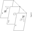
- FRUC uses two different template matching cost functions called: Template and Bilateral, illustrated respectively in the following Figure 4 and Figure 5 .
- Template and Bilateral illustrated respectively in the following Figure 4 and Figure 5 .
- FRUC Bilateral mode is based a similar design as PMMVD.
- the template matching cost is the sum of the SADs between blocks of the current picture, neighboring the current block, and blocks of the reference picture (typically, as shown in Figure 4 , dotted blocks (if available) and dashed blocks (if available)).
- s and r are corresponding pixel locations, respectively in Vcur and in Vref(MV).
- the distortion used in common decoder-side computations gives the same weight to all samples. However, it is common to use weighting factors when such distortion is computed in the encoder, for instance, to take into account the perceptual impact of the samples.
- At least one JVET approach uses a weight per block, computed on the luma signal, based on the local gradients inside the block. Blocks having a high activity (that is, local gradients with high amplitude) are given a lower weight than blocks with low activity.
- weighting is for HDR content. The weighting is dependent on the luma value of the sample.
- the described embodiments address this problem.
- the following paragraphs present exemplary embodiments, such as for computing CCLM or LIC parameters at an encoder or decoder side. Choosing the right transformation to apply to reference pixels based on the reconstructed or decoded neighborhood changes the prediction.
- the described embodiments also present encoder and decoder-side motion vector refinement on FRUC, FRUC bilateral and PMMVD modes. In these cases, choosing the right reference pixels based on the decoded neighborhood changes the reference. But the approaches described could also be generalized to encoder and decoder-side prediction-mode or motion vector selection. In the embodiments, distortions can be compared to determine the coding mode, reference pixels, or motion vector, etc.
- weighting can be applied in DMVD approaches for weighting the samples coming from different pictures, such as in a prior approach dealing with weighted averaging of multiple predictors. But such approaches do not take into account a local importance (weighting) of the samples.
- the described embodiments relate to the decision process applied at the decoder side (and also, for symmetric reasons, at the encoder), for making decisions based on the direct (as in FRUC) or indirect (as in LIC) computation of distortions.
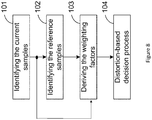
- the decision process is made of four steps.
- a first step (101) the current samples neighborhood, Vcur, that is going to be used for deriving the distortions, is identified.
- Vref the reference samples neighborhood, Vref, that is going to be used for deriving the distortions.
- Step (103) derives the weighting factors W(s), s in Vcur, to be applied for each sample used in the distortion computation.
- This step uses as input data the output of step 101 (the current samples), and possibly the output of step 102 (the reference samples).
- the last step (104) corresponds to the actual decision process, based on the computation of distortions that uses as input, the current samples, the reference samples, and the weighting factors.
- the weighted distortion can be determined from current reconstructed or decoded samples, as well as from reference samples, and is minimized by varying parameters. These parameters can be the reference samples, coding mode, motion vector, or other parameters affecting the distortion. In at least one embodiment described below, parameters within the distortion determination can be varied to minimize the weighted distortion.
- the described embodiment works as follows.
- the goal is to predict the color samples of the current block, from the spatially neighboring color samples, and from co-located neighboring color samples from another color component. For example, it applies to predict the chroma samples of a block from the co-located luma samples block.
- the described embodiment works as follows.
- the goal is to predict the samples of the current block, located at position (xc,yc), from the spatially neighboring samples, and from samples located in a reference picture.
- a motion vector MV(dx,dy) is given.
- the reference block is therefore located at position (xc+dx,yc+dy).
- the described embodiment works as follows.
- the goal is to identify the best motion vector MV(dx,dy), using the spatially neighboring samples of the current block, located at position (xc,yc), and the spatially neighboring samples of the reference block identified by the motion vector MV.
- the reference block is therefore located at position (xc+dx,yc+dy).
- MV is computed to minimize the distortion.
- the described embodiment works as follows.
- the goal is to identify the best motion vector MV(dx,dy), using two reference blocks, located in two reference pictures.
- the current block is considered to be located at position (xc,yc).
- the reference blocks are derived from the position (xc,yc) and from the motion vector MV.
- MV is computed to minimize the distortion.
- the weighting factor can be computed from the current neighborhood, from a reference, or from a combination of those.
- a first method is employed.
- a weight function F(.) is inferred by the decoder, or signaled in the bitstream.
- the weighted factor only depends on the value of the sample from the current picture located at the position r.
- the weighted factor only depends on the value of the luma sample from the current picture located at the position r, even if the distortion computation applies to the chroma samples.
- W r F rec_curY r
- the weight function F(.) can be implemented with:
- SEI message SEI message
- SPS Sequence Parameter Sets
- PPS Picture Parameter Sets
- CTU Coding Tree Unit
- APS Adaptation Picture Sets
- the weighting factors are based on the QP used to code the samples.
- the weight can be computed from any of the references (ref0 or ref1 if available) or the current picture.
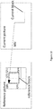
- Figure 10 illustrates a reference block in a reference picture, where the reference block is made of samples from different blocks in the reference picture, with potentially different QPs.
- the weighting factor for a sample located at position s is computed from the QPi used for coding the block to which this sample belongs. We noted QP(s) this QP.
- four different weighting factors should therefore be used.
- W(s) is proportional to 2 (-QP(s)/3) .
- W s K . 2 ⁇ QP s / 3 K being a constant parameter.
- a third method of deriving the weighting parameters is used.
- the weighting factor for a sample position is based on the local activity of the block containing the sample.
- the weighting factors are computed using the samples of the temporally closest reference picture, among the different considered reference pictures (reference 0 and reference 1).
- the weighting factors are computed using the samples of the reference picture whose temporal level in the temporal coding hierarchy is the lowest among the different considered reference pictures (reference 0 and reference 1).
- the weighting factors should be computed based on the samples located in picture R0, which is at a lower temporal hierarchy than the picture R4.
- the weighting factors are computed using the samples from both reference pictures used to derive the motion vector.
- the following policy can be used:
- the weighting factors are computed using the samples of the reference picture, for which the average QP is the lowest.
- the average QP is for example computed as follows. Let (xc,yc) be the location of the current block in the current picture. Let MV(dx,dy) be the motion vector associated to a reference picture. The block in the reference picture is located at (xc+dx,yc+dy). The average QP in the reference block is the average of the QPs used of the samples of the reference block. An illustration is given in Figure 10 , where the reference block is made of samples belonging to different blocks, coded with potentially different QPs.
- the purpose of the described embodiments is to get a more accurate distortion measure in the decoder-side refinement phase.
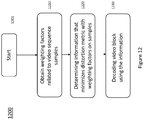
- Figure 12 shows one embodiment of a method 1200 for decoder side prediction based on weighted distortion.
- the method commences at Start block 1201 and proceeds to block 1210 for obtaining weighting factors related to video sequence samples.
- Control proceeds from block 1210 to block 1220 for determining information that minimizes a distortion metric with weighting factors applied to video sequence samples.
- Such information can comprise reference samples, motion vectors, or coding mode to use in the next step.
- Control then proceeds from block 1220 to block 1230 for decoding the video block using the determined information.
- Figure 13 shows one embodiment of a method 1300 for encoder side prediction based on weighted distortion.
- the method commences at Start block 1301 and proceeds to block 1310 for obtaining weighting factors related to video sequence samples.
- Control proceeds from block 1310 to block 1320 for determining information that minimizes a distortion metric with weighting factors applied to video sequence samples.
- Such information can comprise reference samples, motion vectors, or coding mode to use in the next step.
- Control then proceeds from block 1320 to block 1330 for encoding the video block using the determined information.
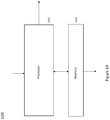
- Figure 14 shows an apparatus 1400 used for prediction based on weighted distortion.
- the apparatus comprises a Processor 1410 and a Memory 1420.
- the Processor 1410 is configured, for encoding, to perform the steps of Figure 13 , that is performing encoding using prediction based on weighted distortion for a portion of a video image using the method of Figure 13 .
- Processor 1410 When Processor 1410 is configured for decoding, it performs the steps of Figure 12 , that is, performing prediction based on weighted distortion for a portion of a video image using the method of Figure 12 .
- processor or “controller” should not be construed to refer exclusively to hardware capable of executing software, and may implicitly include, without limitation, digital signal processor (“DSP”) hardware, read-only memory (“ROM”) for storing software, random access memory (“RAM”), and non-volatile storage.
- DSP digital signal processor
- ROM read-only memory
- RAM random access memory
- any switches shown in the figures are conceptual only. Their function may be carried out through the operation of program logic, through dedicated logic, through the interaction of program control and dedicated logic, or even manually, the particular technique being selectable by the implementer as more specifically understood from the context.
- any element expressed as a means for performing a specified function is intended to encompass any way of performing that function including, for example, a) a combination of circuit elements that performs that function or b) software in any form, including, therefore, firmware, microcode or the like, combined with appropriate circuitry for executing that software to perform the function.
- the present principles as defined by such claims reside in the fact that the functionalities provided by the various recited means are combined and brought together in the manner which the claims call for. It is thus regarded that any means that can provide those functionalities are equivalent to those shown herein.
Landscapes
- Engineering & Computer Science (AREA)
- Multimedia (AREA)
- Signal Processing (AREA)
- Compression Or Coding Systems Of Tv Signals (AREA)
Abstract
Decoders can use prediction based on weighted distortion to determine information used to make decisions regarding motion vectors, reference pixels, and coding modes, similar to a corresponding encoder operation. Samples in and around a current block and samples of reference pictures are weighted and a distortion metric generated to determine the decisions. Embodiments are described for prediction modes such as Cross-component linear model (CCLM), Local Illumination Compensation (LIC), and Frame Rate Up-Conversion (FRUC). Various embodiments describe derivation of weighting factors used in the decision making, comprising inference by a decoder, basing weighting factors on a quantization parameter, local activity of a block, and samples of temporally close reference pictures.
Description
- The present principles relate to video compression and video decoding.
- The domain of the following embodiments is video coding, focused on decoding tools involving the computation of distortion. This for instance relates to Frame-Rate Up Conversion (FRUC), Pattern matched motion vector derivation (PMMVD), both based on Template Matching (TM) techniques, Cross-component linear model (CCLM), Local Illumination Compensation (LIC), and indirectly, Bi-directional Optical flow (BIO). These tools are described within the JVET (Joint Video Exploration Team) committee.
- These tools make decoder decisions based on the computation of local distortion based on spatial or temporal reconstructed signal. This distortion is for example the Sum of Absolute Difference (SAD) between different prediction samples. This means that each sample has the same impact on the overall distortion.
- However, it is well known that all the samples do not have the same perceptual impact. In encoder algorithms, it is therefore very common to introduce sample-dependent weighting values in the distortion computations involved in the encoding decisions.
- The described embodiments propose to use such weighting distortions in the decoder, when the decoder makes use of such distortion computations for making its decisions.
- These and other drawbacks and disadvantages of the prior art are addressed by the present principles, which are directed to a method and apparatus for decoder side prediction based on weighted distortion.
- According to an aspect of the present principles, there is provided a method. The method comprises steps of: obtaining weighting factors related to video sequence samples; determining information that minimizes a distortion metric based on said video sequence samples with said weighting factors applied; and, decoding a current video block using the information.
- According to another aspect of the present principles, there is provided a second method. The method comprises steps of: obtaining weighting factors related to video sequence samples; determining information that minimizes a distortion metric based on said video sequence samples with said weighting factors applied; and, encoding a current video block using the information.
- According to another aspect of the present principles, there is provided an apparatus. The apparatus comprises a memory and a processor. The processor can be configured to encode or decode a block of a video image by obtaining weighting factors related to video sequence samples, determining information that minimizes a distortion metric based on the video sequence samples with the weighting factors applied; and, encoding or decoding the current video block using the information.
- These and other aspects, features and advantages of the present principles will become apparent from the following detailed description of exemplary embodiments, which is to be read in connection with the accompanying drawings.
-
-
Figure 1 shows locations of samples used for the derivation of the CCLM parameters. -
Figure 2 shows neighboring samples used for deriving IC parameters. -
Figure 3 shows in bi-prediction, the L-shapes inreferences -
Figure 4 shows neighboring blocks used in the SAD calculations for Template cost function. -
Figure 5 shows neighboring blocks used in the SAD calculation for Bilateral cost function. -
Figure 6 shows a standard, generic video compression scheme. -
Figure 7 shows a standard, generic video decompression scheme. -
Figure 8 shows a flow diagram for one embodiment of the described approach. -
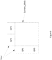
Figure 9 shows locations of the samples used for the derivation of the CCLM parameters. -
Figure 10 shows computation of the weighting factor from a reference block. -
Figure 11 shows an example of temporal coding hierarchy. -
Figure 12 shows one embodiment of a method using the described aspects. -
Figure 13 shows another embodiment of a method using the described aspects. -
Figure 14 shows one embodiment of an apparatus using the described aspects. - The described embodiments propose to use such weighting distortions in the decoder, when the decoder makes use of such distortion computations for making its decisions. By applying weighting while computing the distortion in the decoder, one advantage of these ideas is to obtain improved coding performance.
- Cross-component linear model (CCLM) prediction mode is conceptually close to the LIC (Local Illumination Compensation) mode, but it applies internally to a picture, across color components. Samples from a given color component are predicted from samples from another color component, based on the L-shape of decoded pixels surrounding the current block.
- Typically, this applies to predict the chroma samples from the luma samples. A linear model is used as in LIC:

Figure 1 . As in LIC, the considered distortion is the Mean Square Error (MSE).
CCLM is therefore based on the computation of a local distortion, defined as follows:
- In Inter mode, LIC allows correcting block prediction samples obtained via Motion Compensation (MC) by considering the spatial or temporal local illumination variation possibly. The LIC parameters are estimated by comparing a set of reconstructed samples rec_cur surrounding the current block ("current blk"), located in a neighborhood Vcur, with a set of reconstructed samples rec_ref, located in a neighborhood Vref(MV) of the displaced block in the reference picture ("ref blk"), as depicted in
Figure 2 . Here, MV is the motion displacement between the current block and the reference block. Typically, Vcur and Vref(MV) are made of the L-shape samples, neighboring the current block and reference block, respectively. - The LIC parameters minimize the mean square error difference (MSE) between the samples in Vcur and the samples in Vref(MV), corrected with IC parameters. Typically, the LIC model is linear: LIC(x) = a.x+b = (a)(x)+b.

- In the following, pixel location will be noted either by 1 (e.g. s or r) or 2 variables (e.g. (x,y) or (i,j)).
- In case of Bi-prediction, the LIC parameters (ao,bo) and (a1,b1) are derived independently from Vref0(MV0) and from Vref1 (MV1) respectively (
Figure 3 ). - LIC is therefore based on the computation of a local distortion, defined as follows:

- Decoder-side motion derivation (DMVD) is an inter-prediction tool based on the derivation, at decoder side, of a motion vector based on a distortion-based motion estimation process. DMVD consists in deriving a motion vector, based on distortion function, applied to already reconstructed samples. This kind of function calculates a cost between a reference and a candidate as the Sum of Absolute Differences (SAD) between two blocks of pixels.
- The reference is defined with some neighboring blocks (or CU, PU...) of the current block (or CU, PU...) to be encoded/decoded. The objective is to find the motion vector predictor that minimizes the SAD between the reference blocks (or CU, PU...) and the neighboring blocks (or CU, PU...) of the block pointed by the tested motion vector predictor in the tested reference picture
- Two tools in JVET are currently using this technique, Frame-Rate Up Conversion (FRUC) and Pattern matched motion vector derivation (PMMVD).
- FRUC uses two different template matching cost functions called: Template and Bilateral, illustrated respectively in the following
Figure 4 andFigure 5 . FRUC Bilateral mode is based a similar design as PMMVD. - In FRUC Template mode, the template matching cost is the sum of the SADs between blocks of the current picture, neighboring the current block, and blocks of the reference picture (typically, as shown in
Figure 4 , dotted blocks (if available) and dashed blocks (if available)). Let's note the current block top-left position is p=(xc,yc), and the tested motion vector MV=(dx,dy). - The SAD is computed as follows:

- As in previous case, s and r are corresponding pixel locations, respectively in Vcur and in Vref(MV).
- In FRUC Bilateral mode, as well as in PMMVD, the template matching cost is the SAD between blocks of two different reference pictures (typically, as shown in
Figure 5 , dashed blocks (if available)). If the current block top-left position is (xc,yc), the tested motion vector MV=(dx,dy), the SAD is computed as follows:
reference picture 0, and Vref1(λ.MV) is made of the reference block located at position (xc+λ.dx,yc+λ.dy) in thereference picture 1, λ being a scaling factor taking into account the temporal distance between the picture ref1 and the current picture, relatively to the temporal distance between the picture ref0 and the current picture. Typically, λ = (tref1 - tcur)/(tref0 - tcur), where tcur, tref0 and tref1 are the temporal instances of the current,reference 0 andreference 1 pictures. - The distortion used in common decoder-side computations gives the same weight to all samples. However, it is common to use weighting factors when such distortion is computed in the encoder, for instance, to take into account the perceptual impact of the samples.
- At least one JVET approach uses a weight per block, computed on the luma signal, based on the local gradients inside the block. Blocks having a high activity (that is, local gradients with high amplitude) are given a lower weight than blocks with low activity.
- Another weighting proposed within the JVET committee is for HDR content. The weighting is dependent on the luma value of the sample.
- The application of appropriate weighting at the encoder side generally results in noticeable gain in visual quality (for a same bitrate), by better allocating the bits among the various areas of the pictures. However, this weighting is not applied at the decoder.
- The described embodiments address this problem. The following paragraphs present exemplary embodiments, such as for computing CCLM or LIC parameters at an encoder or decoder side. Choosing the right transformation to apply to reference pixels based on the reconstructed or decoded neighborhood changes the prediction. The described embodiments also present encoder and decoder-side motion vector refinement on FRUC, FRUC bilateral and PMMVD modes. In these cases, choosing the right reference pixels based on the decoded neighborhood changes the reference. But the approaches described could also be generalized to encoder and decoder-side prediction-mode or motion vector selection. In the embodiments, distortions can be compared to determine the coding mode, reference pixels, or motion vector, etc.
- In the prior-art, weighting can be applied in DMVD approaches for weighting the samples coming from different pictures, such as in a prior approach dealing with weighted averaging of multiple predictors. But such approaches do not take into account a local importance (weighting) of the samples.
- The described embodiments relate to the decision process applied at the decoder side (and also, for symmetric reasons, at the encoder), for making decisions based on the direct (as in FRUC) or indirect (as in LIC) computation of distortions.
- The basic concept of the described embodiments is depicted in
Figure 8 . The decision process is made of four steps. In a first step (101) the current samples neighborhood, Vcur, that is going to be used for deriving the distortions, is identified. Similarly, in another step (102) the reference samples neighborhood, Vref, that is going to be used for deriving the distortions, is identified. Step (103) derives the weighting factors W(s), s in Vcur, to be applied for each sample used in the distortion computation. This step uses as input data the output of step 101 (the current samples), and possibly the output of step 102 (the reference samples). The last step (104) corresponds to the actual decision process, based on the computation of distortions that uses as input, the current samples, the reference samples, and the weighting factors. - The weighted distortion can be determined from current reconstructed or decoded samples, as well as from reference samples, and is minimized by varying parameters. These parameters can be the reference samples, coding mode, motion vector, or other parameters affecting the distortion. In at least one embodiment described below, parameters within the distortion determination can be varied to minimize the weighted distortion.
- In a first embodiment, applied to CCLM, the described embodiment works as follows. The goal is to predict the color samples of the current block, from the spatially neighboring color samples, and from co-located neighboring color samples from another color component. For example, it applies to predict the chroma samples of a block from the co-located luma samples block.
- In
step 101, the color samples in the L-shape of the current block, Vcur, are identified. This corresponds to the set Vcur indicated inFigure 1 . - In
step 102, the color samples in the L-shape of the co-located block from the component used to predict the current block, Vref, are identified. This corresponds to the set Vref indicated inFigure 1 . - In
step 103, the weighting factors W(r) to be applied are computed. - In
step 104, the distortion for parameters a,b is computed as follows:
- A normalization factor may be applied as follows:

- In a second embodiment, applied to CCLM, the described embodiment works as follows. The goal is to predict the samples of the current block, located at position (xc,yc), from the spatially neighboring samples, and from samples located in a reference picture. A motion vector MV(dx,dy) is given. The reference block is therefore located at position (xc+dx,yc+dy).
- In
step 101, the samples in the L-shape of the current block, Vcur, are identified. This corresponds to the set Vcur indicated inFigure 2 . - In
step 102, the color samples in the L-shape of the reference block, Vref(MV), are identified. This corresponds to the set Vref(MV) indicated inFigure 2 . - In
step 103, the weighting factors W(r) to be applied are computed. - In
step 104, the distortion for parameters a,b is computed as follows:
- A normalization factor may be applied as follows:

- In a third embodiment, applied to FRUC template mode, the described embodiment works as follows. The goal is to identify the best motion vector MV(dx,dy), using the spatially neighboring samples of the current block, located at position (xc,yc), and the spatially neighboring samples of the reference block identified by the motion vector MV. The reference block is therefore located at position (xc+dx,yc+dy).
- In
step 101, the samples in the L-shape of the current block, Vcur, are identified. This corresponds to the dotted blocks (if available) and dashed blocks (if available) of the current picture inFigure 4 . - In
step 102, the samples in the L-shape of the reference block, Vref(MV), are identified. This corresponds to the dotted blocks (if available) and dashed blocks (if available) of the reference picture inFigure 4 . - In
step 103, the weighting factors W(r) to be applied are computed. - In
step 104, the distortion for motion vector MV is computed as follows:
- MV is computed to minimize the distortion.
- A normalization factor may be applied as follows:

- In a fourth embodiment, applied to FRUC bilateral and PMMVD, the described embodiment works as follows. The goal is to identify the best motion vector MV(dx,dy), using two reference blocks, located in two reference pictures. The current block is considered to be located at position (xc,yc). The reference blocks are derived from the position (xc,yc) and from the motion vector MV.
- In
step 101, the samples in the current block, Vcur, are identified. - In
step 102, the samples in the reference block fromreference picture 0, Vref0(MV), are identified. Similarly, the samples in the reference block fromreference picture 1, Vref1(.MV). - In
step 103, the weighting factors W(r) to be applied are computed. - In
step 104, the distortion for motion vector MV is computed as follows:
- MV is computed to minimize the distortion.
- A normalization factor may be applied as follows:

- In the equations above, the weighting factor can be computed from the current neighborhood, from a reference, or from a combination of those. The distortion to minimize can be computed as follows:

- In a first embodiment used in derivation of weighting factors, a first method is employed. In this embodiment, a weight function F(.) is inferred by the decoder, or signaled in the bitstream.
- The weighting factor for a sample located at position r is derived as follows:

- That is, the weighted factor only depends on the value of the sample from the current picture located at the position r.
- In an embodiment, the weighted factor only depends on the value of the luma sample from the current picture located at the position r, even if the distortion computation applies to the chroma samples.

- The weight function F(.) can be implemented with:
- look-up-tables,
- piece-wise scalar functions,
- piece-wise linear functions,
- piece-wise polynomial functions.
- It can be coded in SEI message, in Sequence Parameter Sets (SPS), Picture Parameter Sets (PPS), in slice header, in Coding Tree Unit (CTU) syntax, per Tile, or in new structure such as Adaptation Picture Sets (APS).
- In a second embodiment employing a second method for computing weighting factors, the weighting factors are based on the QP used to code the samples. This is illustrated in
Figure 9 for spatial prediction, where the current block is surrounded by samples (Vcur) belonging to 4 different blocks, coded with 4 different QPs, QP0 to 3. For the temporal case, the weight can be computed from any of the references (ref0 or ref1 if available) or the current picture.Figure 10 illustrates a reference block in a reference picture, where the reference block is made of samples from different blocks in the reference picture, with potentially different QPs. The weighting factor for a sample located at position s, is computed from the QPi used for coding the block to which this sample belongs. We noted QP(s) this QP. Here, four different weighting factors should therefore be used. - In an embodiment, W(s) is proportional to 2(-QP(s)/3).

- In a third embodiment, a third method of deriving the weighting parameters is used. The weighting factor for a sample position is based on the local activity of the block containing the sample. The local activity locAct in a block B can be for instance computed as follows:


In a variant, we consider for each position s a block Bs centered on the position s, and W(s) = locAct(Bs). The typical size of B is 8x8. - In the case of bilateral motion derivation, the samples from the current block Vcur cannot be used to derive the weighting factors, since they are not yet reconstructed.
- In one embodiment of bilateral motion derivation, the weighting factors are computed using the samples of the temporally closest reference picture, among the different considered reference pictures (
reference 0 and reference 1). - In another embodiment of bilateral motion derivation, the weighting factors are computed using the samples of the reference picture whose temporal level in the temporal coding hierarchy is the lowest among the different considered reference pictures (
reference 0 and reference 1). - For instance, referring to
Figure 11 , let's consider that the current block uses as reference pictures picture R0 and R3. In this embodiment, the weighting factors should be computed based on the samples located in picture R0, which is at a lower temporal hierarchy than the picture R4. - In another embodiment, the weighting factors are computed using the samples from both reference pictures used to derive the motion vector. For example, the following policy can be used:
- Weighting factors W0(p) are computed for each location p inside Vref0(MV), using any of the solutions mentioned above. A normalization over the block can also be applied.
- Weighting factors W1(s) are computed for each location s inside Vref1( .MV), using any of the solutions mentioned above. A normalization over the block can also be applied.
- The final weighting factor for a position p is computed as:

- In another embodiment, the weighting factors are computed using the samples of the reference picture, for which the average QP is the lowest. The average QP is for example computed as follows. Let (xc,yc) be the location of the current block in the current picture. Let MV(dx,dy) be the motion vector associated to a reference picture. The block in the reference picture is located at (xc+dx,yc+dy). The average QP in the reference block is the average of the QPs used of the samples of the reference block. An illustration is given in
Figure 10 , where the reference block is made of samples belonging to different blocks, coded with potentially different QPs. - The average QP (
QP ) is computed as:
- The purpose of the described embodiments is to get a more accurate distortion measure in the decoder-side refinement phase.
- The foregoing paragraphs have presented exemplary embodiments, such as for: a) computing CCLM or LIC parameters at a decoder side (choosing the right transformation to apply to reference pixels based on the decoded neighborhood - changes the prediction), and b) Decoder-side motion vector refinement on FRUC, FRUC bilateral and PMMVD modes (choosing the right reference pixels based on the decoded neighborhood - changes the reference). But it could also be generalized to decoder-side prediction-mode or motion vector selection. When appropriate, corresponding encoder side operations would also be part of the disclosed ideas presented here.
- One embodiment of the aspects described is illustrated in
Figure 12 , which shows one embodiment of amethod 1200 for decoder side prediction based on weighted distortion. The method commences atStart block 1201 and proceeds to block 1210 for obtaining weighting factors related to video sequence samples. Control proceeds fromblock 1210 to block 1220 for determining information that minimizes a distortion metric with weighting factors applied to video sequence samples. Such information can comprise reference samples, motion vectors, or coding mode to use in the next step. Control then proceeds fromblock 1220 to block 1230 for decoding the video block using the determined information. - Another embodiment of the aspects described is illustrated in
Figure 13 , which shows one embodiment of amethod 1300 for encoder side prediction based on weighted distortion. The method commences atStart block 1301 and proceeds to block 1310 for obtaining weighting factors related to video sequence samples. Control proceeds fromblock 1310 to block 1320 for determining information that minimizes a distortion metric with weighting factors applied to video sequence samples. Such information can comprise reference samples, motion vectors, or coding mode to use in the next step. Control then proceeds fromblock 1320 to block 1330 for encoding the video block using the determined information. - One embodiment of the aspects described is illustrated in
Figure 14 , which shows anapparatus 1400 used for prediction based on weighted distortion. The apparatus comprises aProcessor 1410 and aMemory 1420. TheProcessor 1410 is configured, for encoding, to perform the steps ofFigure 13 , that is performing encoding using prediction based on weighted distortion for a portion of a video image using the method ofFigure 13 . - When
Processor 1410 is configured for decoding, it performs the steps ofFigure 12 , that is, performing prediction based on weighted distortion for a portion of a video image using the method ofFigure 12 . - The functions of the various elements shown in the figures may be provided through the use of dedicated hardware as well as hardware capable of executing software in association with appropriate software. When provided by a processor, the functions may be provided by a single dedicated processor, by a single shared processor, or by a plurality of individual processors, some of which may be shared. Moreover, explicit use of the term "processor" or "controller" should not be construed to refer exclusively to hardware capable of executing software, and may implicitly include, without limitation, digital signal processor ("DSP") hardware, read-only memory ("ROM") for storing software, random access memory ("RAM"), and non-volatile storage.
- Other hardware, conventional and/or custom, may also be included. Similarly, any switches shown in the figures are conceptual only. Their function may be carried out through the operation of program logic, through dedicated logic, through the interaction of program control and dedicated logic, or even manually, the particular technique being selectable by the implementer as more specifically understood from the context.
- The present description illustrates the present principles. It will thus be appreciated that those skilled in the art will be able to devise various arrangements that, although not explicitly described or shown herein, embody the present principles and are included within its spirit and scope.
- All examples and conditional language recited herein are intended for pedagogical purposes to aid the reader in understanding the present principles and the concepts contributed by the inventor(s) to furthering the art, and are to be construed as being without limitation to such specifically recited examples and conditions.
- Moreover, all statements herein reciting principles, aspects, and embodiments of the present principles, as well as specific examples thereof, are intended to encompass both structural and functional equivalents thereof. Additionally, it is intended that such equivalents include both currently known equivalents as well as equivalents developed in the future, i.e., any elements developed that perform the same function, regardless of structure.
- Thus, for example, it will be appreciated by those skilled in the art that the block diagrams presented herein represent conceptual views of illustrative circuitry embodying the present principles. Similarly, it will be appreciated that any flow charts, flow diagrams, state transition diagrams, pseudocode, and the like represent various processes which may be substantially represented in computer readable media and so executed by a computer or processor, whether or not such computer or processor is explicitly shown.
- In the claims hereof, any element expressed as a means for performing a specified function is intended to encompass any way of performing that function including, for example, a) a combination of circuit elements that performs that function or b) software in any form, including, therefore, firmware, microcode or the like, combined with appropriate circuitry for executing that software to perform the function. The present principles as defined by such claims reside in the fact that the functionalities provided by the various recited means are combined and brought together in the manner which the claims call for. It is thus regarded that any means that can provide those functionalities are equivalent to those shown herein.
- Reference in the specification to "one embodiment" or "an embodiment" of the present principles, as well as other variations thereof, means that a particular feature, structure, characteristic, and so forth described in connection with the embodiment is included in at least one embodiment of the present principles. Thus, the appearances of the phrase "in one embodiment" or "in an embodiment", as well any other variations, appearing in various places throughout the specification are not necessarily all referring to the same embodiment.
Claims (15)
- A method, comprising:obtaining weighting factors related to video sequence samples;determining information that minimizes a distortion metric, based on said video sequence samples, with said weighting factors applied; and,decoding a current video block using said information.
- An apparatus for decoding a block of image data, comprising:a memory, anda processor, configured to:obtain weighting factors related to video sequence samples;determine information that minimizes a distortion metric, based on said video sequence samples, with said weighting factors applied; and,decode a current video block using said information.
- A method, comprising:obtaining weighting factors related to video sequence samples;determining information that minimizes a distortion metric, based on said video sequence samples, with said weighting factors applied; and,encoding a current video block using said information.
- An apparatus for decoding a block of image data, comprising:a memory, anda processor, configured to:obtain weighting factors related to video sequence samples;determine information that minimizes a distortion metric, based on said video sequence samples, with said weighting factors applied; and,encode a current video block using said information.
- The method of Claim 1 or 3 or the apparatus of Claim 2 or 4, wherein said video sequence samples comprise at least one of a neighboring region of a current video block and at least one reference picture.
- The method of Claim 1 or 3 or the apparatus of Claim 2 or 4, wherein said information comprises reference samples or at least one motion vector.
- The method of Claim 1 or 3 or the apparatus of Claim 2 or 4, wherein the distortion metric is computed for chroma samples.
- The method of Claim 1 or 3 or the apparatus of Claim 2 or 4, wherein said weighting factors are based on a function of said video sequence samples.
- The method of Claim 1 or 3 or the apparatus of Claim 2 or 4, wherein said weighting factors are based on a quantization parameter used to code said video sequence samples.
- The method of Claim 1 or 3 or the apparatus of Claim 2 or 4, wherein said weighting factors are based on local activity of said current video block.
- The method of Claim 1 or 3 or the apparatus of Claim 2 or 4, wherein said information is used to determine a coding mode for the current video block.
- The method of Claim 1 or 3 or the apparatus of Claim 2 or 4, wherein information is used to determine samples to use as references for the current video block.
- A non-transitory computer readable medium containing data content generated according to the method of any one of claims 3 and 5 to 12, or by the apparatus of any one of claims 4 and 5 to 12, for playback using a processor.
- A signal comprising video data generated according to the method of any one of claims 3 and 5 to 12, or by the apparatus of any one of claims 4 and 5 to 12, for playback using a processor.
- A computer program product comprising instructions which, when the program is executed by a computer, cause the computer to carry out the method of any one of claims 1 and 5 to 12.
Priority Applications (6)
| Application Number | Priority Date | Filing Date | Title |
|---|---|---|---|
| EP18305356.0A EP3547686A1 (en) | 2018-03-29 | 2018-03-29 | Method and apparatus for decoder side prediction based on weighted distortion |
| KR1020207027596A KR20200136407A (en) | 2018-03-29 | 2019-03-25 | Method and apparatus for decoder-side prediction based on weighted distortion |
| CN201980020689.5A CN111903128B (en) | 2018-03-29 | 2019-03-25 | Decoder-side prediction method and device based on weighted distortion |
| PCT/US2019/023821 WO2019190955A1 (en) | 2018-03-29 | 2019-03-25 | Method and apparatus for decorder side prediction based on weighted distortion |
| US17/041,157 US20210014523A1 (en) | 2018-03-29 | 2019-03-25 | Method and apparatus for decoder side prediction based on weighted distortion |
| EP19713672.4A EP3777160A1 (en) | 2018-03-29 | 2019-03-25 | Method and apparatus for decorder side prediction based on weighted distortion |
Applications Claiming Priority (1)
| Application Number | Priority Date | Filing Date | Title |
|---|---|---|---|
| EP18305356.0A EP3547686A1 (en) | 2018-03-29 | 2018-03-29 | Method and apparatus for decoder side prediction based on weighted distortion |
Publications (1)
| Publication Number | Publication Date |
|---|---|
| EP3547686A1 true EP3547686A1 (en) | 2019-10-02 |
Family
ID=61965873
Family Applications (2)
| Application Number | Title | Priority Date | Filing Date |
|---|---|---|---|
| EP18305356.0A Withdrawn EP3547686A1 (en) | 2018-03-29 | 2018-03-29 | Method and apparatus for decoder side prediction based on weighted distortion |
| EP19713672.4A Pending EP3777160A1 (en) | 2018-03-29 | 2019-03-25 | Method and apparatus for decorder side prediction based on weighted distortion |
Family Applications After (1)
| Application Number | Title | Priority Date | Filing Date |
|---|---|---|---|
| EP19713672.4A Pending EP3777160A1 (en) | 2018-03-29 | 2019-03-25 | Method and apparatus for decorder side prediction based on weighted distortion |
Country Status (5)
| Country | Link |
|---|---|
| US (1) | US20210014523A1 (en) |
| EP (2) | EP3547686A1 (en) |
| KR (1) | KR20200136407A (en) |
| CN (1) | CN111903128B (en) |
| WO (1) | WO2019190955A1 (en) |
Families Citing this family (5)
| Publication number | Priority date | Publication date | Assignee | Title |
|---|---|---|---|---|
| US11671616B2 (en) | 2021-03-12 | 2023-06-06 | Lemon Inc. | Motion candidate derivation |
| US11936899B2 (en) * | 2021-03-12 | 2024-03-19 | Lemon Inc. | Methods and systems for motion candidate derivation |
| US12219166B2 (en) | 2021-03-12 | 2025-02-04 | Lemon Inc. | Motion candidate derivation with search order and coding mode |
| US12166998B2 (en) * | 2022-01-12 | 2024-12-10 | Tencent America LLC | Adjustment based local illumination compensation |
| WO2024137862A1 (en) * | 2022-12-22 | 2024-06-27 | Bytedance Inc. | Method, apparatus, and medium for video processing |
Citations (2)
| Publication number | Priority date | Publication date | Assignee | Title |
|---|---|---|---|---|
| EP1521477A1 (en) * | 2003-10-01 | 2005-04-06 | Thomson Licensing S.A. | Differential video coding method |
| WO2017123133A1 (en) * | 2016-01-12 | 2017-07-20 | Telefonaktiebolaget Lm Ericsson (Publ) | Video coding using hybrid intra prediction |
Family Cites Families (11)
| Publication number | Priority date | Publication date | Assignee | Title |
|---|---|---|---|---|
| WO2007084475A2 (en) * | 2006-01-17 | 2007-07-26 | Thomson Licensing | Methods and apparatus for low complexity error resilient motion estimation and coding mode selection |
| JP2010503264A (en) * | 2006-08-28 | 2010-01-28 | トムソン ライセンシング | Method and apparatus for determining expected distortion in a decoded video block |
| JP5554831B2 (en) * | 2009-04-28 | 2014-07-23 | テレフオンアクチーボラゲット エル エム エリクソン(パブル) | Distortion weighting |
| KR20110068792A (en) * | 2009-12-16 | 2011-06-22 | 한국전자통신연구원 | Adaptive Image Coding Apparatus and Method |
| GB2492163B (en) * | 2011-06-24 | 2018-05-02 | Skype | Video coding |
| US9948938B2 (en) * | 2011-07-21 | 2018-04-17 | Texas Instruments Incorporated | Methods and systems for chroma residual data prediction |
| US9998727B2 (en) * | 2012-09-19 | 2018-06-12 | Qualcomm Incorporated | Advanced inter-view residual prediction in multiview or 3-dimensional video coding |
| CN107810635A (en) * | 2015-06-16 | 2018-03-16 | Lg 电子株式会社 | Method and apparatus based on illuminance compensation prediction block in image compiling system |
| US10419757B2 (en) * | 2016-08-31 | 2019-09-17 | Qualcomm Incorporated | Cross-component filter |
| US11025903B2 (en) * | 2017-01-13 | 2021-06-01 | Qualcomm Incorporated | Coding video data using derived chroma mode |
| US10694181B2 (en) * | 2017-01-27 | 2020-06-23 | Qualcomm Incorporated | Bilateral filters in video coding with reduced complexity |
-
2018
- 2018-03-29 EP EP18305356.0A patent/EP3547686A1/en not_active Withdrawn
-
2019
- 2019-03-25 CN CN201980020689.5A patent/CN111903128B/en active Active
- 2019-03-25 EP EP19713672.4A patent/EP3777160A1/en active Pending
- 2019-03-25 US US17/041,157 patent/US20210014523A1/en not_active Abandoned
- 2019-03-25 WO PCT/US2019/023821 patent/WO2019190955A1/en not_active Ceased
- 2019-03-25 KR KR1020207027596A patent/KR20200136407A/en active Pending
Patent Citations (2)
| Publication number | Priority date | Publication date | Assignee | Title |
|---|---|---|---|---|
| EP1521477A1 (en) * | 2003-10-01 | 2005-04-06 | Thomson Licensing S.A. | Differential video coding method |
| WO2017123133A1 (en) * | 2016-01-12 | 2017-07-20 | Telefonaktiebolaget Lm Ericsson (Publ) | Video coding using hybrid intra prediction |
Non-Patent Citations (2)
| Title |
|---|
| FRANCOIS E ET AL: "AHG7: Comments on metrics for extended colour volume content", 6. JVET MEETING; 31-3-2017 - 7-4-2017; HOBART; (THE JOINT VIDEO EXPLORATION TEAM OF ISO/IEC JTC1/SC29/WG11 AND ITU-T SG.16 ); URL: HTTP://PHENIX.INT-EVRY.FR/JVET/,, no. JVET-F0089, 31 March 2017 (2017-03-31), XP030150764 * |
| PERCEPTUALLY OPTIMIZED QP ADAPTATION AND ASSOCIATED DISTORTION MEASURE: "Perceptually optimized QP adaptation and associated distortion measure", 8. JVET MEETING; 18-10-2017 - 25-10-2017; MACAU; (THE JOINT VIDEO EXPLORATION TEAM OF ISO/IEC JTC1/SC29/WG11 AND ITU-T SG.16 ); URL: HTTP://PHENIX.INT-EVRY.FR/JVET/,, no. JVET-H0047, 10 October 2017 (2017-10-10), XP030151035 * |
Also Published As
| Publication number | Publication date |
|---|---|
| CN111903128A (en) | 2020-11-06 |
| US20210014523A1 (en) | 2021-01-14 |
| KR20200136407A (en) | 2020-12-07 |
| CN111903128B (en) | 2025-04-22 |
| EP3777160A1 (en) | 2021-02-17 |
| WO2019190955A1 (en) | 2019-10-03 |
Similar Documents
| Publication | Publication Date | Title |
|---|---|---|
| JP7726962B2 (en) | Block Size Limits for DMVR | |
| US11470348B2 (en) | Methods and apparatuses of video processing with bi-direction prediction in video coding systems | |
| US20210014523A1 (en) | Method and apparatus for decoder side prediction based on weighted distortion | |
| JP7769061B2 (en) | Motion compensation in video encoding and decoding | |
| US11172203B2 (en) | Intra merge prediction | |
| JP7507279B2 (en) | Method and apparatus for adaptive illumination compensation in video encoding and decoding - Patents.com | |
| US8498336B2 (en) | Method and apparatus for adaptive weight selection for motion compensated prediction | |
| US9215475B2 (en) | Method and apparatus for motion estimation using combined reference bi-prediction | |
| WO2023131298A1 (en) | Boundary matching for video coding | |
| US20260039857A1 (en) | Method, apparatus, and medium for video processing | |
| US20250310513A1 (en) | Prediction refinement with convolution model | |
| US20260039818A1 (en) | Method, apparatus, and medium for video processing | |
| US20250379967A1 (en) | Method, apparatus, and medium for video processing | |
| WO2025011483A1 (en) | Local illumination compensation with merge slope adjustment | |
| GB2577056A (en) | Bitstream decoder | |
| WO2025157169A1 (en) | Extrapolation intra prediction model for inter chroma coding | |
| WO2025157170A1 (en) | Blended candidates for cross-component model merge mode | |
| WO2025148956A1 (en) | Regression-based blending for improving intra prediction with neighboring template | |
| WO2026046374A1 (en) | Adaptive predictor blending and processing order in overlapped blocks | |
| US20250317599A1 (en) | Method, apparatus, and medium for video processing | |
| US20250330568A1 (en) | Updating motion attributes of merge candidates | |
| WO2025157172A1 (en) | Inheriting blended candidates of cross-component merge mode for inter-chroma | |
| US20250337904A1 (en) | Method, apparatus, and medium for video processing | |
| US20260019629A1 (en) | Method, apparatus, and medium for video processing | |
| US20260143129A1 (en) | Method, apparatus, and medium for video processing |
Legal Events
| Date | Code | Title | Description |
|---|---|---|---|
| PUAI | Public reference made under article 153(3) epc to a published international application that has entered the european phase |
Free format text: ORIGINAL CODE: 0009012 |
|
| AK | Designated contracting states |
Kind code of ref document: A1 Designated state(s): AL AT BE BG CH CY CZ DE DK EE ES FI FR GB GR HR HU IE IS IT LI LT LU LV MC MK MT NL NO PL PT RO RS SE SI SK SM TR |
|
| AX | Request for extension of the european patent |
Extension state: BA ME |
|
| RAP1 | Party data changed (applicant data changed or rights of an application transferred) |
Owner name: INTERDIGITAL VC HOLDINGS, INC. |
|
| STAA | Information on the status of an ep patent application or granted ep patent |
Free format text: STATUS: THE APPLICATION IS DEEMED TO BE WITHDRAWN |
|
| 18D | Application deemed to be withdrawn |
Effective date: 20200603 |