EP3547514A1 - Power conversion device - Google Patents
Power conversion device Download PDFInfo
- Publication number
- EP3547514A1 EP3547514A1 EP16922533.1A EP16922533A EP3547514A1 EP 3547514 A1 EP3547514 A1 EP 3547514A1 EP 16922533 A EP16922533 A EP 16922533A EP 3547514 A1 EP3547514 A1 EP 3547514A1
- Authority
- EP
- European Patent Office
- Prior art keywords
- motor
- abnormality
- power conversion
- conversion device
- motor rotation
- Prior art date
- Legal status (The legal status is an assumption and is not a legal conclusion. Google has not performed a legal analysis and makes no representation as to the accuracy of the status listed.)
- Granted
Links
Images



Classifications
-
- H—ELECTRICITY
- H02—GENERATION; CONVERSION OR DISTRIBUTION OF ELECTRIC POWER
- H02P—CONTROL OR REGULATION OF ELECTRIC MOTORS, ELECTRIC GENERATORS OR DYNAMO-ELECTRIC CONVERTERS; CONTROLLING TRANSFORMERS, REACTORS OR CHOKE COILS
- H02P29/00—Arrangements for regulating or controlling electric motors, appropriate for both AC and DC motors
- H02P29/50—Reduction of harmonics
-
- G—PHYSICS
- G01—MEASURING; TESTING
- G01H—MEASUREMENT OF MECHANICAL VIBRATIONS OR ULTRASONIC, SONIC OR INFRASONIC WAVES
- G01H1/00—Measuring characteristics of vibrations in solids by using direct conduction to the detector
- G01H1/003—Measuring characteristics of vibrations in solids by using direct conduction to the detector of rotating machines
-
- H—ELECTRICITY
- H02—GENERATION; CONVERSION OR DISTRIBUTION OF ELECTRIC POWER
- H02M—APPARATUS FOR CONVERSION BETWEEN AC AND AC, BETWEEN AC AND DC, OR BETWEEN DC AND DC, AND FOR USE WITH MAINS OR SIMILAR POWER SUPPLY SYSTEMS; CONVERSION OF DC OR AC INPUT POWER INTO SURGE OUTPUT POWER; CONTROL OR REGULATION THEREOF
- H02M1/00—Details of apparatus for conversion
- H02M1/32—Means for protecting converters other than automatic disconnection
- H02M1/325—Means for protecting converters other than automatic disconnection with means for allowing continuous operation despite a fault, i.e. fault tolerant converters
-
- H—ELECTRICITY
- H02—GENERATION; CONVERSION OR DISTRIBUTION OF ELECTRIC POWER
- H02M—APPARATUS FOR CONVERSION BETWEEN AC AND AC, BETWEEN AC AND DC, OR BETWEEN DC AND DC, AND FOR USE WITH MAINS OR SIMILAR POWER SUPPLY SYSTEMS; CONVERSION OF DC OR AC INPUT POWER INTO SURGE OUTPUT POWER; CONTROL OR REGULATION THEREOF
- H02M7/00—Conversion of AC power input into DC power output; Conversion of DC power input into AC power output
- H02M7/42—Conversion of DC power input into AC power output without possibility of reversal
- H02M7/44—Conversion of DC power input into AC power output without possibility of reversal by static converters
- H02M7/48—Conversion of DC power input into AC power output without possibility of reversal by static converters using discharge tubes with control electrode or semiconductor devices with control electrode
- H02M7/53—Conversion of DC power input into AC power output without possibility of reversal by static converters using discharge tubes with control electrode or semiconductor devices with control electrode using devices of a triode or transistor type requiring continuous application of a control signal
- H02M7/537—Conversion of DC power input into AC power output without possibility of reversal by static converters using discharge tubes with control electrode or semiconductor devices with control electrode using devices of a triode or transistor type requiring continuous application of a control signal using semiconductor devices only, e.g. single switched pulse inverters
- H02M7/5387—Conversion of DC power input into AC power output without possibility of reversal by static converters using discharge tubes with control electrode or semiconductor devices with control electrode using devices of a triode or transistor type requiring continuous application of a control signal using semiconductor devices only, e.g. single switched pulse inverters in a bridge configuration
- H02M7/53871—Conversion of DC power input into AC power output without possibility of reversal by static converters using discharge tubes with control electrode or semiconductor devices with control electrode using devices of a triode or transistor type requiring continuous application of a control signal using semiconductor devices only, e.g. single switched pulse inverters in a bridge configuration with automatic control of output voltage or current
- H02M7/53873—Conversion of DC power input into AC power output without possibility of reversal by static converters using discharge tubes with control electrode or semiconductor devices with control electrode using devices of a triode or transistor type requiring continuous application of a control signal using semiconductor devices only, e.g. single switched pulse inverters in a bridge configuration with automatic control of output voltage or current with digital control
-
- H—ELECTRICITY
- H02—GENERATION; CONVERSION OR DISTRIBUTION OF ELECTRIC POWER
- H02P—CONTROL OR REGULATION OF ELECTRIC MOTORS, ELECTRIC GENERATORS OR DYNAMO-ELECTRIC CONVERTERS; CONTROLLING TRANSFORMERS, REACTORS OR CHOKE COILS
- H02P29/00—Arrangements for regulating or controlling electric motors, appropriate for both AC and DC motors
- H02P29/02—Providing protection against overload without automatic interruption of supply
- H02P29/024—Detecting a fault condition, e.g. short circuit, locked rotor, open circuit or loss of load
Definitions
- the present invention relates to a power conversion device such as an inverter, and more particularly to a power conversion device that diagnoses abnormality of a motor or a machine driven by the motor.
- PTL 1 describes a method of diagnosing abnormality of a motor or a machine driven by the motor, in which a vibration sensor is attached to the motor or the machine driven by the motor, and the abnormality is diagnosed based on a detection signal of vibration by the sensor when the motor inertially rotates within a predetermined rotational speed region.
- PTL 2 describes that an acoustic sensor, which is less expensive than a vibration sensor, is used. That is, described is a method of diagnosing abnormality of a motor or a machine driven by the motor, in which the acoustic sensor is attached to the motor or the machine driven by the motor, and the abnormality is diagnosed from a signal of the acoustic sensor.
- Both PTLs 1 and 2 have a problem that the sensor comes off from the motor or the machine driven by the motor with time since the sensor is attached to the motor or the machine driven by the motor. They also have a problem with the detection accuracy of abnormality.
- An object of the present invention is to solve the above problems and provide a power conversion device that diagnoses abnormality of a motor or a machine driven by the motor with high reliability and high accuracy.
- the present invention is a power conversion device including: an acoustic sensor; an interface unit configured to input a sound pressure signal acquired by the acoustic sensor when a motor is driven, and to receive motor rotation information; an accumulation unit configured to accumulate the sound pressure signal and the motor rotation information from the interface unit; an abnormality detection unit configured to detect abnormality based on a relationship between the sound pressure signal and the motor rotation information; and an external output unit configured to output the abnormality when the abnormality is detected by the abnormality detection unit.
- the present invention it is possible to output the detected abnormality to the outside without installing a sensor in a motor or a machine driven by the motor and eliminate a possibility that a sensor comes off from the motor or the machine driven by the motor with time when the sensor is directly attached to the motor or the machine driven by the motor.
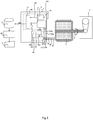
- FIG. 1 shows a first embodiment according to the present invention.
- a power conversion device (inverter) 1 is electrically connected to a motor 3 by three-phase motor lines 2a, 2b and 2c.
- the motor drives a machine 5 having a rotor through a motor rotating shaft 4.
- the motor wire 2a is provided with a current sensor 10a that measures a motor driving current.
- the motor wire 2c is provided with a current sensor 10b that measures the motor driving current.
- an arithmetic section 11 provided in a microcomputer 90 generates a driving command 110 for an IGBT.
- the driving command 101 from the microcomputer 90 is amplified by a gate driving circuit 30 to control the IGBT 40 to be on or off, thereby controlling the motor current to drive the motor with the torque command and the motor rotation speed from the outside.
- an acoustic sensor 20 is provided outside the inverter 1 and measures the sound of the motor or the machine driven by the motor.
- a signal 103 measured by the acoustic sensor 20 is converted from an analog signal into a digital signal 104 by an analog-to-digital converter (A/D converter) 12.
- the digitized signal 104 of the acoustic sensor 20, a torque command 102, and motor rotation speed information 101 are accumulated in a data accumulation means 50 outside the microcomputer 90 through an interface circuit 13.
- a time-dependent change is detected by an abnormality detection device 60 from the accumulated data in the data accumulation means 50, and an operator is notified of abnormality through an external output unit 70 when the abnormality is detected.
- the operation of the first embodiment according to the present invention will be described in detail by using the flowchart in FIG. 2 .
- a power converter starts operation (200)
- the present invention also starts operation.
- the analog information 103 by the acoustic sensor is converted into the digital signal 104 by the analog-to-digital converter (A/D converter) 12 and inputted into the interface circuit 203.
- the torque command 102 and the motor rotation speed information 101 are inputted into the interface circuit 13 from the arithmetic section 11.
- a signal is sent from the interface circuit 13 to the data accumulation means 50, and the data is accumulated in the data accumulation means 50.
- the abnormality detection device 60 judges abnormality from the time-dependent change in the data in the data accumulation means 50 by a determination means 201, the operator is notified of the abnormality through the external output unit 70.
- a time measurement unit may be provided although not shown, or time information may be acquired from the outside.
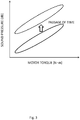
- FIG. 3 A method of detecting abnormality from a time-dependent change in the relationship between the motor torque and the sound pressure will be described with FIG. 3 .
- the sound pressure increases in proportion to the motor torque during normal operation.
- the motor rotation speed resonates with the eigenvalue frequency of the machine driven by the motor, the sound pressure increases.
- the relationship between the motor torque and the sound pressure is distributed in a certain range as shown in FIG. 3 .
- Abnormality is detected by catching the time-dependent change in this relationship.
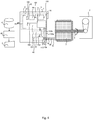
- FIG. 4 shows a second embodiment according to the present invention.
- a frequency signal 105 and a sound pressure signal 106 are further generated by a fast Fourier transform (FFT) converter 80 from a signal, which is obtained by converting a signal 103 measured by a sensor 20 into a digital signal 104 from the analog signal 103 by an analog-to-digital converter (A/D converter) in the first embodiment, and a data accumulation means 50 accumulates the frequency signal 105, the sound pressure signal 106, a torque command 102 and motor rotation speed information 101 through an interface circuit 13.
- FFT fast Fourier transform
- the present invention also starts operation.
- the analog information 103 by the acoustic sensor is converted into the digital signal 104 by the analog-to-digital converter (A/D converter) 12, and the frequency signal 105 and the sound pressure signal 106 are further generated by the fast Fourier transform (FFT) converter 80.
- the frequency signal 105 and the sound pressure signal 106 are inputted into the interface circuit 203.
- the torque command 102 and the motor rotation speed information 101 are inputted into the interface circuit 13 from the arithmetic section 11.
- a signal is sent from the interface circuit 13 to the data accumulation means 50, and the data is accumulated in the data accumulation means 50.
- an abnormality detection device 60 judges abnormality from a time-dependent change in the data in the data accumulation means 50 by a determination means 201, the operator is notified of the abnormality through an external output unit 70.
- FIG. 6 A method of detecting abnormality from the time-dependent change in the relationship between the motor rotation speed and the sound frequency acquired by the acoustic sensor will be described with FIG. 6 .
- the sound is roughly classified into two types with the motor rotation speed as the horizontal axis and the sound frequency acquired by the acoustic sensor as the vertical axis.
- One is a sound that does not depend on the motor rotation speed and corresponds to the natural vibration frequency of the motor or the machine driven by the motor.
- the other is a sound proportional to the motor rotation speed.
- a new sound (sound 3) proportional to the motor rotation speed is generated.
- the abnormality detection device 60 can detect abnormality.
- FIG. 7 A method of detecting abnormality from the time-dependent change in the relationship between the time and the sound frequency acquired by the acoustic sensor will be described with FIG. 7 .
- the time is the horizontal axis
- the sound frequency acquired by the acoustic sensor is the vertical axis.
- FIG. 8 shows a third embodiment according to the present invention.
- an interface circuit 13 of a power conversion device 1 is connected to a data accumulation means 50 provided in another site via a network 300.
- a network 300 By thus connecting the data accumulation means 50 via the network 300, it is possible to keep more data amount, that is, data for a longer period of time than a case where the data accumulation means 50 is provided in the power conversion device 1 as shown in FIG. 1 , enabling monitoring for a longer period of time.
- FIG. 9 shows a fourth embodiment according to the present invention.
- a plurality of acoustic sensors 20a and 20b are provided, signals thereof are converted into digital signals 104a and 103b by analog-to-digital converters (A/D converters) 12a and 12b, respectively, and fast Fourier transform (FFT) converters 80a and 80b are further provided.
- A/D converters analog-to-digital converters
- FFT fast Fourier transform
- FIG. 10 shows a fifth embodiment according to the present invention.
- the analog-to-digital converter (A/D converter) 12 and the fast Fourier transform (FFT) converter 80 utilize a circuit incorporated in the microcomputer 90.
- A/D converter analog-to-digital converter
- FFT fast Fourier transform
- a microcomputer different from an IGBT driving microcomputer 90 or a field-programmable gate array (FPGA) 91 is provided.
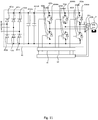
- FIG. 11 shows a driving circuit for driving a motor 3.
- Diodes 401a to 401f constitute a three-phase diode bridge.
- the anode of the diode 401a and the cathode of 401b are connected to the R phase input of the three-phase.
- the anode of the diode 401c and the cathode of 401d are connected to the S phase input
- the anode of the diode 401e and the cathode of 401f are connected to the T phase input.
- the alternating current is full-wave rectified by the three-phase diode bridge constituted by the diodes 401a to 401f, the ripple components are removed by smoothing capacitors 4022a and 4022b, and the alternating current becomes a direct current.
- the cathodes of diodes 4044a to 4044f are connected to the collectors of IGBTs 403a to 403f, and the anodes of the diodes 4044a to 4044f are connected to the emitters of the IGBTs 403a to f.
- the collectors of the IGBTs 403a, 403c and 403e are connected to the diodes 401a, 401c and 401d and the smoothing capacitors 4022a and 4022b, and the emitters of the IGBTs 403b, 403d and 403f are connected to the diodes 401b, 401, 401d and 401f and the smoothing capacitors 4022a and 4022b.
- a gate driving circuit 40 is connected to the gates of the IGBTs 3a to f.
- the emitter of the IGBT 403a and the collector of the IGBT 403b are connected to the U phase of the motor 3.
- the emitter of the IGBT 403c and the collector of the IGBT 3d are connected to the V phase of the motor 3
- the emitter of the IGBT 403e and the collector of the IGBT 4033f are connected to the W phase of the motor 3.
- the diodes 401a to 401f, the IGBTs 403a to 403f and the diodes 4044a to 4044f are stored in one module 30.
- a current sensor 10a is provided for the wiring among the U phase of the motor 5, the emitter of the IGBT 403a and the collector of the IGBT 403b, and a current sensor 10b is provided for the wiring among V phase of the motor 500, the emitter of the IGBT 403e and the collector of the IGBT 403f.
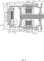
- FIG. 12 shows a sixth embodiment according to the present invention.
- Wires 621a and 621b are wound around electromagnetic steel sheets 620a and 620b, and the electromagnetic steel sheets 620a and b and the wires 621a and 621b constitute a stator.
- Magnets 624a to d are housed in cases 623a and 623b, and the cases 623a and 623b and the magnets 624a to 624d constitute a rotor.
- the stator and the rotor are housed in a motor housing 700.
- motor housing cooling fins 601a and 601b are provided on the surface of the motor housing 700.
- the motor housing cooling fins 601a and 601b are provided along the circumference of the motor.
- a bearing 606a is provided to support the motor rotating shaft 4.
- the motor housing 700 is connected to a flange 602 by screws 607a and 607b.
- the motor rotating shaft 4 is instructed by the bearing 606a connected to the flange 602.
- the flange 602 is fixed to a mechanical device not shown in the drawing by bolt holes 608a and 608b.
- an inverter housing 710 is connected to the motor housing 700 by bolts 711a and 611b.
- a back face cooling fin 612 is connected to the inverter housing 710 by bolts 613a and 613b.
- the back face cooling fin 612 is provided with a cooling fan 641 through pedestals 640a and 640b.
- a print 550 is provided on the module 30, and capacitors 402a and 402b, a microcomputer 90, an acoustic sensor 20 and a gate driving circuit 40 are provided.
- a wind tunnel cover 600 that covers the cooling fan 641, the inverter housing 710, the motor housing 700 and the cooling fin 612 is provided.
- the acoustic sensor 40 is covered with the inverter housing 710 and sounds other than the motor are blocked, only the sound of the motor can be picked, enabling highly accurate measurement and abnormality detection.
Landscapes
- Engineering & Computer Science (AREA)
- Power Engineering (AREA)
- Physics & Mathematics (AREA)
- General Physics & Mathematics (AREA)
- Inverter Devices (AREA)
- Measurement Of Mechanical Vibrations Or Ultrasonic Waves (AREA)
- Power Conversion In General (AREA)
- Testing Of Devices, Machine Parts, Or Other Structures Thereof (AREA)
Abstract
Description
- The present invention relates to a power conversion device such as an inverter, and more particularly to a power conversion device that diagnoses abnormality of a motor or a machine driven by the motor.
- Many parts that will be worn out, such as bearings, are used for a motor and a machine driven by the motor. Conventionally, periodic inspection is performed to check whether there is abnormality, but there are many steps for the work such as disassembly, leading to expensive maintenance. Moreover, when a mechanical section is incorporated in the device and cannot be easily disassembled, it is necessary to periodically replace part of the device such as a belt or the entire device, which is expensive. Furthermore, there are also many machines used for 20 years or more, such as railroads, automobiles, building air conditioning and elevators, and high reliability is also required.
- Therefore, the constitution has been proposed in which abnormality is detected without disassembling the motor and the machine driven by the motor.
-
PTL 1 describes a method of diagnosing abnormality of a motor or a machine driven by the motor, in which a vibration sensor is attached to the motor or the machine driven by the motor, and the abnormality is diagnosed based on a detection signal of vibration by the sensor when the motor inertially rotates within a predetermined rotational speed region. - Moreover,
PTL 2 describes that an acoustic sensor, which is less expensive than a vibration sensor, is used. That is, described is a method of diagnosing abnormality of a motor or a machine driven by the motor, in which the acoustic sensor is attached to the motor or the machine driven by the motor, and the abnormality is diagnosed from a signal of the acoustic sensor. -
- PTL 1:
JP 4581693 B2 - PTL 2:
JP H1-45011 A - Both
PTLs - An object of the present invention is to solve the above problems and provide a power conversion device that diagnoses abnormality of a motor or a machine driven by the motor with high reliability and high accuracy.
- The present invention is a power conversion device including: an acoustic sensor; an interface unit configured to input a sound pressure signal acquired by the acoustic sensor when a motor is driven, and to receive motor rotation information; an accumulation unit configured to accumulate the sound pressure signal and the motor rotation information from the interface unit; an abnormality detection unit configured to detect abnormality based on a relationship between the sound pressure signal and the motor rotation information; and an external output unit configured to output the abnormality when the abnormality is detected by the abnormality detection unit.
- According to the present invention, it is possible to output the detected abnormality to the outside without installing a sensor in a motor or a machine driven by the motor and eliminate a possibility that a sensor comes off from the motor or the machine driven by the motor with time when the sensor is directly attached to the motor or the machine driven by the motor.
- It is also possible to improve accuracy by detecting abnormality from the relationships among the torque of the power conversion device, the motor rotation speed and the sound pressure acquired by the acoustic sensor.
-
-
FIG. 1 is a diagram showing a first embodiment according to the present invention. -
FIG. 2 is a flowchart for explaining the operation of the first embodiment according to the present invention. -
FIG. 3 is a diagram for explaining a method of detecting abnormality from a time-dependent change in the relationship between the motor torque and the sound pressure in the present invention. -
FIG. 4 is a diagram showing a second embodiment according to the present invention. -
FIG. 5 is a flowchart for explaining the operation of the second embodiment according to the present invention. -
FIG. 6 is a diagram for explaining a first method of detecting abnormality from a time-dependent change in the relationship between the motor rotation speed and the sound frequency acquired by the acoustic sensor in the present invention. -
FIG. 7 is a diagram for explaining a second method of detecting abnormality from a time-dependent change in the relationship between the time and the sound frequency acquired by the acoustic sensor in the present invention. -
FIG. 8 is a diagram showing a third embodiment according to the present invention. -
FIG. 9 is a diagram showing a fourth embodiment according to the present invention. -
FIG. 10 is a diagram showing a fifth embodiment according to the present invention. -
FIG. 11 is a diagram showing a driving circuit for driving a three-phase permanent magnet motor. -
FIG. 12 is a diagram showing a sixth embodiment according to the present invention. -
FIG. 1 shows a first embodiment according to the present invention. A power conversion device (inverter) 1 is electrically connected to amotor 3 by three-phase motor lines machine 5 having a rotor through a motor rotating shaft 4. Themotor wire 2a is provided with acurrent sensor 10a that measures a motor driving current. Moreover, themotor wire 2c is provided with acurrent sensor 10b that measures the motor driving current. Based oncurrent sensor signals arithmetic section 11 provided in amicrocomputer 90 generates adriving command 110 for an IGBT. Thedriving command 101 from themicrocomputer 90 is amplified by agate driving circuit 30 to control the IGBT 40 to be on or off, thereby controlling the motor current to drive the motor with the torque command and the motor rotation speed from the outside. - In the present invention, an
acoustic sensor 20 is provided outside theinverter 1 and measures the sound of the motor or the machine driven by the motor. Asignal 103 measured by theacoustic sensor 20 is converted from an analog signal into adigital signal 104 by an analog-to-digital converter (A/D converter) 12. The digitizedsignal 104 of theacoustic sensor 20, atorque command 102, and motorrotation speed information 101 are accumulated in a data accumulation means 50 outside themicrocomputer 90 through aninterface circuit 13. A time-dependent change is detected by anabnormality detection device 60 from the accumulated data in the data accumulation means 50, and an operator is notified of abnormality through anexternal output unit 70 when the abnormality is detected. - Furthermore, the operation of the first embodiment according to the present invention will be described in detail by using the flowchart in
FIG. 2 . When a power converter starts operation (200), the present invention also starts operation. Theanalog information 103 by the acoustic sensor is converted into thedigital signal 104 by the analog-to-digital converter (A/D converter) 12 and inputted into the interface circuit 203. Thetorque command 102 and the motorrotation speed information 101 are inputted into theinterface circuit 13 from thearithmetic section 11. A signal is sent from theinterface circuit 13 to the data accumulation means 50, and the data is accumulated in the data accumulation means 50. When theabnormality detection device 60 judges abnormality from the time-dependent change in the data in the data accumulation means 50 by a determination means 201, the operator is notified of the abnormality through theexternal output unit 70. In order to grasp the time-dependent change, a time measurement unit may be provided although not shown, or time information may be acquired from the outside. - A method of detecting abnormality from a time-dependent change in the relationship between the motor torque and the sound pressure will be described with
FIG. 3 . With respect to the motor torque, the sound pressure increases in proportion to the motor torque during normal operation. However, when the motor rotation speed resonates with the eigenvalue frequency of the machine driven by the motor, the sound pressure increases. Thus, the relationship between the motor torque and the sound pressure is distributed in a certain range as shown inFIG. 3 . Abnormality is detected by catching the time-dependent change in this relationship. -
FIG. 4 shows a second embodiment according to the present invention. Afrequency signal 105 and asound pressure signal 106 are further generated by a fast Fourier transform (FFT)converter 80 from a signal, which is obtained by converting asignal 103 measured by asensor 20 into adigital signal 104 from theanalog signal 103 by an analog-to-digital converter (A/D converter) in the first embodiment, and a data accumulation means 50 accumulates thefrequency signal 105, thesound pressure signal 106, atorque command 102 and motorrotation speed information 101 through aninterface circuit 13. - Furthermore, the operation of the second embodiment according to the present invention will be described in detail by using the flowchart in
FIG. 5 . When a power converter starts operation (200), the present invention also starts operation. Theanalog information 103 by the acoustic sensor is converted into thedigital signal 104 by the analog-to-digital converter (A/D converter) 12, and thefrequency signal 105 and thesound pressure signal 106 are further generated by the fast Fourier transform (FFT)converter 80. Thefrequency signal 105 and the sound pressure signal 106 are inputted into the interface circuit 203. Thetorque command 102 and the motorrotation speed information 101 are inputted into theinterface circuit 13 from thearithmetic section 11. A signal is sent from theinterface circuit 13 to the data accumulation means 50, and the data is accumulated in the data accumulation means 50. When anabnormality detection device 60 judges abnormality from a time-dependent change in the data in the data accumulation means 50 by a determination means 201, the operator is notified of the abnormality through anexternal output unit 70. - A method of detecting abnormality from the time-dependent change in the relationship between the motor rotation speed and the sound frequency acquired by the acoustic sensor will be described with
FIG. 6 . The sound is roughly classified into two types with the motor rotation speed as the horizontal axis and the sound frequency acquired by the acoustic sensor as the vertical axis. One is a sound that does not depend on the motor rotation speed and corresponds to the natural vibration frequency of the motor or the machine driven by the motor. The other is a sound proportional to the motor rotation speed. When the motor or a rotor such as a bearing of the machine driven by the motor is damaged, a new sound (sound 3) proportional to the motor rotation speed is generated. By using this sound, theabnormality detection device 60 can detect abnormality. - A method of detecting abnormality from the time-dependent change in the relationship between the time and the sound frequency acquired by the acoustic sensor will be described with
FIG. 7 . The time is the horizontal axis, and the sound frequency acquired by the acoustic sensor is the vertical axis. When themotor 3 or the rotor such as a bearing of the machine driven by the motor is damaged and comes into contact with a specific sliding portion, abnormality can be detected by measuring the sound generated at a specific frequency interval with thedetection device 60. -
FIG. 8 shows a third embodiment according to the present invention. In the third embodiment, aninterface circuit 13 of apower conversion device 1 is connected to a data accumulation means 50 provided in another site via anetwork 300. By thus connecting the data accumulation means 50 via thenetwork 300, it is possible to keep more data amount, that is, data for a longer period of time than a case where the data accumulation means 50 is provided in thepower conversion device 1 as shown inFIG. 1 , enabling monitoring for a longer period of time. -
FIG. 9 shows a fourth embodiment according to the present invention. In the present invention, a plurality ofacoustic sensors digital signals converters -
FIG. 10 shows a fifth embodiment according to the present invention. InFIGS. 4 and9 , the analog-to-digital converter (A/D converter) 12 and the fast Fourier transform (FFT)converter 80 utilize a circuit incorporated in themicrocomputer 90. However, since the calculation amounts of the A/D conversion and the FFT are large, there is a possibility that themicrocomputer 90 cannot process them all. Thus, a microcomputer different from anIGBT driving microcomputer 90 or a field-programmable gate array (FPGA) 91 is provided. -
FIG. 11 shows a driving circuit for driving amotor 3.Diodes 401a to 401f constitute a three-phase diode bridge. The anode of thediode 401a and the cathode of 401b are connected to the R phase input of the three-phase. Similarly, the anode of thediode 401c and the cathode of 401d are connected to the S phase input, and the anode of thediode 401e and the cathode of 401f are connected to the T phase input. The alternating current is full-wave rectified by the three-phase diode bridge constituted by thediodes 401a to 401f, the ripple components are removed by smoothingcapacitors - The cathodes of
diodes 4044a to 4044f are connected to the collectors of IGBTs 403a to 403f, and the anodes of thediodes 4044a to 4044f are connected to the emitters of the IGBTs 403a to f. The collectors of theIGBTs diodes capacitors IGBTs diodes capacitors gate driving circuit 40 is connected to the gates of the IGBTs 3a to f. The emitter of theIGBT 403a and the collector of the IGBT 403b are connected to the U phase of themotor 3. Similarly, the emitter of theIGBT 403c and the collector of the IGBT 3d are connected to the V phase of themotor 3, and the emitter of theIGBT 403e and the collector of the IGBT 4033f are connected to the W phase of themotor 3. - In
FIG. 11 , thediodes 401a to 401f, theIGBTs 403a to 403f and thediodes 4044a to 4044f are stored in onemodule 30. Acurrent sensor 10a is provided for the wiring among the U phase of themotor 5, the emitter of theIGBT 403a and the collector of the IGBT 403b, and acurrent sensor 10b is provided for the wiring among V phase of the motor 500, the emitter of theIGBT 403e and the collector of theIGBT 403f. -
FIG. 12 shows a sixth embodiment according to the present invention. Wires 621a and 621b are wound aroundelectromagnetic steel sheets 620a and 620b, and the electromagnetic steel sheets 620a and b and the wires 621a and 621b constitute a stator. Magnets 624a to d are housed incases cases motor housing 700. On the surface of themotor housing 700, motorhousing cooling fins housing cooling fins cases motor housing 700 and the left end portion of the motor inFIG. 2 , abearing 606a is provided to support the motor rotating shaft 4. Themotor housing 700 is connected to aflange 602 byscrews bearing 606a connected to theflange 602. Theflange 602 is fixed to a mechanical device not shown in the drawing bybolt holes motor housing 700, aninverter housing 710 is connected to themotor housing 700 bybolts - On the back face of the
inverter housing 710, a backface cooling fin 612 is connected to theinverter housing 710 bybolts face cooling fin 612 is provided with a coolingfan 641 throughpedestals module 30, andcapacitors 402a and 402b, amicrocomputer 90, anacoustic sensor 20 and agate driving circuit 40 are provided. Awind tunnel cover 600 that covers the coolingfan 641, theinverter housing 710, themotor housing 700 and the coolingfin 612 is provided. - In the present invention, since the
acoustic sensor 40 is covered with theinverter housing 710 and sounds other than the motor are blocked, only the sound of the motor can be picked, enabling highly accurate measurement and abnormality detection. -
- 1
- power conversion device (inverter)
- 2a to c
- motor line
- 3
- motor
- 4
- motor rotating shaft
- 5
- machine
- 12
- analog-to-digital converter (A/D converter)
- 13
- interface circuit
- 20
- acoustic sensor
- 30
- gate driving circuit
- 40
- IGBT
- 50
- data accumulation means
- 60
- abnormality detection device
- 70
- external output unit
- 80
- fast Fourier transform (FFT) converter
- 90
- microcomputer
- 100a, 100b
- current sensor signal
- 110
- gate driving signal
- 102
- IGBT driving signal
- 103
- acoustic sensor signal
- 104
- digitized acoustic sensor signal
- 105
- frequency signal
- 106
- sound pressure signal
- 200
- driving command
- 201
- determination means
- 300
- network
Claims (8)
- A power conversion device comprising:an acoustic sensor;an interface unit configured to input a sound pressure signal acquired by the acoustic sensor when a motor is driven, and to receive motor rotation information;an accumulation unit configured to accumulate the sound pressure signal and the motor rotation information from the interface unit;an abnormality detection unit configured to detect abnormality based on a relationship between the sound pressure signal and the motor rotation information; andan external output unit configured to output the abnormality when the abnormality is detected by the abnormality detection unit.
- The power conversion device according to claim 1, wherein
torque, as the motor rotation information, and the sound pressure signal are accumulated in the accumulation unit, and
the abnormality detection unit is configured to detect, as the abnormality, a change in a relationship between the sound pressure signal and the torque over time. - The power conversion device according to claim 1, wherein
a sound frequency signal is generated by a fast Fourier transform (FFT) converter from data acquired by the acoustic sensor,
the interface unit is configured to input a motor rotation speed as the motor rotation information, and
the abnormality detection unit is configured to detect, as the abnormality, occurrence of a sound in which the sound frequency signal changes as the motor rotation speed change in a relationship between the motor rotation speed and the sound frequency signal. - The power conversion device according to claim 3, wherein the abnormality detection unit is configured to detect, as the abnormality, periodic occurrence of a sound signal with a specific frequency in a relationship between the frequency signal and time.
- The power conversion device according to any one of claims 1 to 4, wherein the accumulation unit is provided outside the power conversion device via a network.
- The power conversion device according to any one of claims 1 to 5, comprising a plurality of acoustic sensors.
- The power conversion device according to any one of claims 2 to 6, wherein the FFT converter is provided separately from a motor driving microcomputer.
- The power conversion device according to any one of claims 1 to 6, wherein the acoustic sensor is provided with a shielding portion that blocks sounds other than a sound of the motor.
Applications Claiming Priority (1)
| Application Number | Priority Date | Filing Date | Title |
|---|---|---|---|
| PCT/JP2016/084881 WO2018096640A1 (en) | 2016-11-25 | 2016-11-25 | Power conversion device |
Publications (3)
| Publication Number | Publication Date |
|---|---|
| EP3547514A1 true EP3547514A1 (en) | 2019-10-02 |
| EP3547514A4 EP3547514A4 (en) | 2020-07-22 |
| EP3547514B1 EP3547514B1 (en) | 2023-07-12 |
Family
ID=62195829
Family Applications (1)
| Application Number | Title | Priority Date | Filing Date |
|---|---|---|---|
| EP16922533.1A Active EP3547514B1 (en) | 2016-11-25 | 2016-11-25 | Power conversion device |
Country Status (3)
| Country | Link |
|---|---|
| EP (1) | EP3547514B1 (en) |
| JP (1) | JP6646164B2 (en) |
| WO (1) | WO2018096640A1 (en) |
Families Citing this family (4)
| Publication number | Priority date | Publication date | Assignee | Title |
|---|---|---|---|---|
| DE102018211848B3 (en) * | 2018-07-17 | 2019-11-07 | Ziehl-Abegg Se | Electric motor, fan and system consisting of electric motor and evaluation unit |
| JP7077426B2 (en) * | 2019-01-29 | 2022-05-30 | Primetals Technologies Japan株式会社 | Diagnostic device and equipment equipped with it and diagnostic method |
| CN110531736A (en) * | 2019-08-13 | 2019-12-03 | 中国航空工业集团公司西安飞行自动控制研究所 | A high-power motor controller fault monitoring circuit and method thereof |
| JP7261325B2 (en) * | 2020-02-05 | 2023-04-19 | Primetals Technologies Japan株式会社 | Monitoring device, abnormality diagnosis device, monitoring method and abnormality diagnosis method |
Family Cites Families (6)
| Publication number | Priority date | Publication date | Assignee | Title |
|---|---|---|---|---|
| JPS54147882A (en) * | 1978-05-12 | 1979-11-19 | Hitachi Ltd | Abnormality occurrence detecting method of rotating machine using acoustic signals |
| JPS62195891A (en) * | 1986-02-24 | 1987-08-28 | 松下電器産業株式会社 | Heating cooker |
| US6507790B1 (en) * | 1998-07-15 | 2003-01-14 | Horton, Inc. | Acoustic monitor |
| JP3864146B2 (en) * | 2003-03-18 | 2006-12-27 | 株式会社東芝 | Bearing diagnosis device for rotating machine, bearing diagnosis system for rotating machine, portable terminal and function expansion card |
| JP2011191181A (en) * | 2010-03-15 | 2011-09-29 | Toshiba Industrial Products Manufacturing Corp | Abnormality diagnostic system of rotary apparatus, abnormality diagnostic device of the same, and abnormality diagnosis method of the same |
| KR20130115488A (en) * | 2012-04-12 | 2013-10-22 | 엘에스산전 주식회사 | Apparatus for alarming inverter status and apparatus for analyzing motor status in mobile terminal |
-
2016
- 2016-11-25 JP JP2018552343A patent/JP6646164B2/en active Active
- 2016-11-25 WO PCT/JP2016/084881 patent/WO2018096640A1/en not_active Ceased
- 2016-11-25 EP EP16922533.1A patent/EP3547514B1/en active Active
Also Published As
| Publication number | Publication date |
|---|---|
| JP6646164B2 (en) | 2020-02-14 |
| EP3547514B1 (en) | 2023-07-12 |
| EP3547514A4 (en) | 2020-07-22 |
| JPWO2018096640A1 (en) | 2019-06-24 |
| WO2018096640A1 (en) | 2018-05-31 |
Similar Documents
| Publication | Publication Date | Title |
|---|---|---|
| EP3547514B1 (en) | Power conversion device | |
| US7322794B2 (en) | Method and apparatus for condition-based monitoring of wind turbine components | |
| CN1075633C (en) | Method and device in a bearing | |
| JP5875734B2 (en) | Diagnostic device and switching device for electric motor | |
| JP6353694B2 (en) | Deterioration diagnosis system | |
| JPWO2018109993A1 (en) | Power transmission mechanism abnormality diagnosis device and power transmission mechanism abnormality diagnosis method | |
| CN1039114A (en) | The turbine blade vibration monitor that shroud is arranged | |
| US7168324B2 (en) | Vibration information transmission apparatus and vibration monitoring/analyzing system | |
| JP2019518168A (en) | Pump assembly, method and computer program | |
| CN113647013A (en) | Abnormal diagnosis device of electric motor equipment, abnormal diagnosis method of electric motor equipment, and abnormal diagnosis system of electric motor equipment | |
| KR20190132841A (en) | A Diagnosis Apparatus For Rotating Machinery Using Complex Signals | |
| JPWO2020039661A1 (en) | Abnormality diagnostic device | |
| CN116710658A (en) | Bearing wear monitoring | |
| KR101801299B1 (en) | Drive control device for motor using fault diagnosis information | |
| US20100242748A1 (en) | Press machine | |
| US10396699B2 (en) | Anomaly diagnosing device and anomaly diagnosing method | |
| EP3828648A1 (en) | Motor speed estimation for drive safety system | |
| CN108802611A (en) | Apparatus for diagnosis of abnormality and abnormality diagnostic method | |
| EP3691112B1 (en) | Data obtaining method, inverter, and rotating electric machine | |
| Skóra et al. | Detection and compensation of transistor and position sensors faults in PM BLDCM drives | |
| JP6752368B2 (en) | Rotating machine diagnostic equipment, diagnostic methods and rotating machine system | |
| CN217401239U (en) | Control system for quickly starting mining fan by high-voltage frequency converter | |
| WO2021176761A1 (en) | Device monitoring device and device monitoring method | |
| Szentirmai et al. | Computerised fault diagnosis of induction motor drives | |
| US20250361906A1 (en) | Bearing fault detection |
Legal Events
| Date | Code | Title | Description |
|---|---|---|---|
| STAA | Information on the status of an ep patent application or granted ep patent |
Free format text: STATUS: THE INTERNATIONAL PUBLICATION HAS BEEN MADE |
|
| PUAI | Public reference made under article 153(3) epc to a published international application that has entered the european phase |
Free format text: ORIGINAL CODE: 0009012 |
|
| STAA | Information on the status of an ep patent application or granted ep patent |
Free format text: STATUS: REQUEST FOR EXAMINATION WAS MADE |
|
| 17P | Request for examination filed |
Effective date: 20190409 |
|
| AK | Designated contracting states |
Kind code of ref document: A1 Designated state(s): AL AT BE BG CH CY CZ DE DK EE ES FI FR GB GR HR HU IE IS IT LI LT LU LV MC MK MT NL NO PL PT RO RS SE SI SK SM TR |
|
| AX | Request for extension of the european patent |
Extension state: BA ME |
|
| DAV | Request for validation of the european patent (deleted) | ||
| DAX | Request for extension of the european patent (deleted) | ||
| A4 | Supplementary search report drawn up and despatched |
Effective date: 20200619 |
|
| RIC1 | Information provided on ipc code assigned before grant |
Ipc: H02P 29/024 20160101ALI20200615BHEP Ipc: G01H 17/00 20060101ALI20200615BHEP Ipc: G01H 1/00 20060101ALI20200615BHEP Ipc: G01M 99/00 20110101ALI20200615BHEP Ipc: H02M 7/48 20070101ALI20200615BHEP Ipc: H02M 1/00 20060101AFI20200615BHEP Ipc: H02P 29/50 20160101ALI20200615BHEP |
|
| RIN1 | Information on inventor provided before grant (corrected) |
Inventor name: SAKURAI, NAOKI |
|
| STAA | Information on the status of an ep patent application or granted ep patent |
Free format text: STATUS: EXAMINATION IS IN PROGRESS |
|
| 17Q | First examination report despatched |
Effective date: 20211208 |
|
| REG | Reference to a national code |
Ref legal event code: R079 Ipc: H02P0029024000 Ref country code: DE Ref legal event code: R079 Ref document number: 602016081082 Country of ref document: DE Free format text: PREVIOUS MAIN CLASS: H02M0001000000 Ipc: H02P0029024000 |
|
| GRAP | Despatch of communication of intention to grant a patent |
Free format text: ORIGINAL CODE: EPIDOSNIGR1 |
|
| STAA | Information on the status of an ep patent application or granted ep patent |
Free format text: STATUS: GRANT OF PATENT IS INTENDED |
|
| RIC1 | Information provided on ipc code assigned before grant |
Ipc: H02M 7/5387 19850101ALI20230102BHEP Ipc: H02M 1/32 20070101ALI20230102BHEP Ipc: H02M 7/48 19680901ALI20230102BHEP Ipc: G01M 99/00 20110101ALI20230102BHEP Ipc: G01H 17/00 19850101ALI20230102BHEP Ipc: H02M 1/00 19680901ALI20230102BHEP Ipc: H02P 29/50 20160101ALI20230102BHEP Ipc: G01H 1/00 19680901ALI20230102BHEP Ipc: H02P 29/024 20160101AFI20230102BHEP |
|
| INTG | Intention to grant announced |
Effective date: 20230202 |
|
| GRAS | Grant fee paid |
Free format text: ORIGINAL CODE: EPIDOSNIGR3 |
|
| GRAA | (expected) grant |
Free format text: ORIGINAL CODE: 0009210 |
|
| STAA | Information on the status of an ep patent application or granted ep patent |
Free format text: STATUS: THE PATENT HAS BEEN GRANTED |
|
| AK | Designated contracting states |
Kind code of ref document: B1 Designated state(s): AL AT BE BG CH CY CZ DE DK EE ES FI FR GB GR HR HU IE IS IT LI LT LU LV MC MK MT NL NO PL PT RO RS SE SI SK SM TR |
|
| REG | Reference to a national code |
Ref country code: CH Ref legal event code: EP |
|
| REG | Reference to a national code |
Ref country code: IE Ref legal event code: FG4D |
|
| REG | Reference to a national code |
Ref country code: DE Ref legal event code: R096 Ref document number: 602016081082 Country of ref document: DE |
|
| REG | Reference to a national code |
Ref country code: LT Ref legal event code: MG9D |
|
| REG | Reference to a national code |
Ref country code: NL Ref legal event code: MP Effective date: 20230712 |
|
| REG | Reference to a national code |
Ref country code: AT Ref legal event code: MK05 Ref document number: 1588176 Country of ref document: AT Kind code of ref document: T Effective date: 20230712 |
|
| PG25 | Lapsed in a contracting state [announced via postgrant information from national office to epo] |
Ref country code: NL Free format text: LAPSE BECAUSE OF FAILURE TO SUBMIT A TRANSLATION OF THE DESCRIPTION OR TO PAY THE FEE WITHIN THE PRESCRIBED TIME-LIMIT Effective date: 20230712 |
|
| PG25 | Lapsed in a contracting state [announced via postgrant information from national office to epo] |
Ref country code: GR Free format text: LAPSE BECAUSE OF FAILURE TO SUBMIT A TRANSLATION OF THE DESCRIPTION OR TO PAY THE FEE WITHIN THE PRESCRIBED TIME-LIMIT Effective date: 20231013 |
|
| PG25 | Lapsed in a contracting state [announced via postgrant information from national office to epo] |
Ref country code: ES Free format text: LAPSE BECAUSE OF FAILURE TO SUBMIT A TRANSLATION OF THE DESCRIPTION OR TO PAY THE FEE WITHIN THE PRESCRIBED TIME-LIMIT Effective date: 20230712 |
|
| PG25 | Lapsed in a contracting state [announced via postgrant information from national office to epo] |
Ref country code: IS Free format text: LAPSE BECAUSE OF FAILURE TO SUBMIT A TRANSLATION OF THE DESCRIPTION OR TO PAY THE FEE WITHIN THE PRESCRIBED TIME-LIMIT Effective date: 20231112 |
|
| PG25 | Lapsed in a contracting state [announced via postgrant information from national office to epo] |
Ref country code: SE Free format text: LAPSE BECAUSE OF FAILURE TO SUBMIT A TRANSLATION OF THE DESCRIPTION OR TO PAY THE FEE WITHIN THE PRESCRIBED TIME-LIMIT Effective date: 20230712 Ref country code: RS Free format text: LAPSE BECAUSE OF FAILURE TO SUBMIT A TRANSLATION OF THE DESCRIPTION OR TO PAY THE FEE WITHIN THE PRESCRIBED TIME-LIMIT Effective date: 20230712 Ref country code: PT Free format text: LAPSE BECAUSE OF FAILURE TO SUBMIT A TRANSLATION OF THE DESCRIPTION OR TO PAY THE FEE WITHIN THE PRESCRIBED TIME-LIMIT Effective date: 20231113 Ref country code: NO Free format text: LAPSE BECAUSE OF FAILURE TO SUBMIT A TRANSLATION OF THE DESCRIPTION OR TO PAY THE FEE WITHIN THE PRESCRIBED TIME-LIMIT Effective date: 20231012 Ref country code: LV Free format text: LAPSE BECAUSE OF FAILURE TO SUBMIT A TRANSLATION OF THE DESCRIPTION OR TO PAY THE FEE WITHIN THE PRESCRIBED TIME-LIMIT Effective date: 20230712 Ref country code: LT Free format text: LAPSE BECAUSE OF FAILURE TO SUBMIT A TRANSLATION OF THE DESCRIPTION OR TO PAY THE FEE WITHIN THE PRESCRIBED TIME-LIMIT Effective date: 20230712 Ref country code: IS Free format text: LAPSE BECAUSE OF FAILURE TO SUBMIT A TRANSLATION OF THE DESCRIPTION OR TO PAY THE FEE WITHIN THE PRESCRIBED TIME-LIMIT Effective date: 20231112 Ref country code: HR Free format text: LAPSE BECAUSE OF FAILURE TO SUBMIT A TRANSLATION OF THE DESCRIPTION OR TO PAY THE FEE WITHIN THE PRESCRIBED TIME-LIMIT Effective date: 20230712 Ref country code: GR Free format text: LAPSE BECAUSE OF FAILURE TO SUBMIT A TRANSLATION OF THE DESCRIPTION OR TO PAY THE FEE WITHIN THE PRESCRIBED TIME-LIMIT Effective date: 20231013 Ref country code: FI Free format text: LAPSE BECAUSE OF FAILURE TO SUBMIT A TRANSLATION OF THE DESCRIPTION OR TO PAY THE FEE WITHIN THE PRESCRIBED TIME-LIMIT Effective date: 20230712 Ref country code: ES Free format text: LAPSE BECAUSE OF FAILURE TO SUBMIT A TRANSLATION OF THE DESCRIPTION OR TO PAY THE FEE WITHIN THE PRESCRIBED TIME-LIMIT Effective date: 20230712 Ref country code: AT Free format text: LAPSE BECAUSE OF FAILURE TO SUBMIT A TRANSLATION OF THE DESCRIPTION OR TO PAY THE FEE WITHIN THE PRESCRIBED TIME-LIMIT Effective date: 20230712 |
|
| PG25 | Lapsed in a contracting state [announced via postgrant information from national office to epo] |
Ref country code: PL Free format text: LAPSE BECAUSE OF FAILURE TO SUBMIT A TRANSLATION OF THE DESCRIPTION OR TO PAY THE FEE WITHIN THE PRESCRIBED TIME-LIMIT Effective date: 20230712 |
|
| REG | Reference to a national code |
Ref country code: DE Ref legal event code: R097 Ref document number: 602016081082 Country of ref document: DE |
|
| PG25 | Lapsed in a contracting state [announced via postgrant information from national office to epo] |
Ref country code: SM Free format text: LAPSE BECAUSE OF FAILURE TO SUBMIT A TRANSLATION OF THE DESCRIPTION OR TO PAY THE FEE WITHIN THE PRESCRIBED TIME-LIMIT Effective date: 20230712 Ref country code: RO Free format text: LAPSE BECAUSE OF FAILURE TO SUBMIT A TRANSLATION OF THE DESCRIPTION OR TO PAY THE FEE WITHIN THE PRESCRIBED TIME-LIMIT Effective date: 20230712 Ref country code: EE Free format text: LAPSE BECAUSE OF FAILURE TO SUBMIT A TRANSLATION OF THE DESCRIPTION OR TO PAY THE FEE WITHIN THE PRESCRIBED TIME-LIMIT Effective date: 20230712 Ref country code: DK Free format text: LAPSE BECAUSE OF FAILURE TO SUBMIT A TRANSLATION OF THE DESCRIPTION OR TO PAY THE FEE WITHIN THE PRESCRIBED TIME-LIMIT Effective date: 20230712 Ref country code: CZ Free format text: LAPSE BECAUSE OF FAILURE TO SUBMIT A TRANSLATION OF THE DESCRIPTION OR TO PAY THE FEE WITHIN THE PRESCRIBED TIME-LIMIT Effective date: 20230712 Ref country code: SK Free format text: LAPSE BECAUSE OF FAILURE TO SUBMIT A TRANSLATION OF THE DESCRIPTION OR TO PAY THE FEE WITHIN THE PRESCRIBED TIME-LIMIT Effective date: 20230712 |
|
| PLBE | No opposition filed within time limit |
Free format text: ORIGINAL CODE: 0009261 |
|
| STAA | Information on the status of an ep patent application or granted ep patent |
Free format text: STATUS: NO OPPOSITION FILED WITHIN TIME LIMIT |
|
| PG25 | Lapsed in a contracting state [announced via postgrant information from national office to epo] |
Ref country code: IT Free format text: LAPSE BECAUSE OF FAILURE TO SUBMIT A TRANSLATION OF THE DESCRIPTION OR TO PAY THE FEE WITHIN THE PRESCRIBED TIME-LIMIT Effective date: 20230712 |
|
| 26N | No opposition filed |
Effective date: 20240415 |
|
| REG | Reference to a national code |
Ref country code: CH Ref legal event code: PL |
|
| PG25 | Lapsed in a contracting state [announced via postgrant information from national office to epo] |
Ref country code: MC Free format text: LAPSE BECAUSE OF FAILURE TO SUBMIT A TRANSLATION OF THE DESCRIPTION OR TO PAY THE FEE WITHIN THE PRESCRIBED TIME-LIMIT Effective date: 20230712 |
|
| PG25 | Lapsed in a contracting state [announced via postgrant information from national office to epo] |
Ref country code: LU Free format text: LAPSE BECAUSE OF NON-PAYMENT OF DUE FEES Effective date: 20231125 |
|
| PG25 | Lapsed in a contracting state [announced via postgrant information from national office to epo] |
Ref country code: CH Free format text: LAPSE BECAUSE OF NON-PAYMENT OF DUE FEES Effective date: 20231130 |
|
| GBPC | Gb: european patent ceased through non-payment of renewal fee |
Effective date: 20231125 |
|
| PG25 | Lapsed in a contracting state [announced via postgrant information from national office to epo] |
Ref country code: MC Free format text: LAPSE BECAUSE OF FAILURE TO SUBMIT A TRANSLATION OF THE DESCRIPTION OR TO PAY THE FEE WITHIN THE PRESCRIBED TIME-LIMIT Effective date: 20230712 Ref country code: LU Free format text: LAPSE BECAUSE OF NON-PAYMENT OF DUE FEES Effective date: 20231125 Ref country code: CH Free format text: LAPSE BECAUSE OF NON-PAYMENT OF DUE FEES Effective date: 20231130 Ref country code: SI Free format text: LAPSE BECAUSE OF FAILURE TO SUBMIT A TRANSLATION OF THE DESCRIPTION OR TO PAY THE FEE WITHIN THE PRESCRIBED TIME-LIMIT Effective date: 20230712 |
|
| REG | Reference to a national code |
Ref country code: BE Ref legal event code: MM Effective date: 20231130 |
|
| REG | Reference to a national code |
Ref country code: IE Ref legal event code: MM4A |
|
| PG25 | Lapsed in a contracting state [announced via postgrant information from national office to epo] |
Ref country code: IE Free format text: LAPSE BECAUSE OF NON-PAYMENT OF DUE FEES Effective date: 20231125 |
|
| PG25 | Lapsed in a contracting state [announced via postgrant information from national office to epo] |
Ref country code: GB Free format text: LAPSE BECAUSE OF NON-PAYMENT OF DUE FEES Effective date: 20231125 |
|
| PG25 | Lapsed in a contracting state [announced via postgrant information from national office to epo] |
Ref country code: BE Free format text: LAPSE BECAUSE OF NON-PAYMENT OF DUE FEES Effective date: 20231130 |
|
| PG25 | Lapsed in a contracting state [announced via postgrant information from national office to epo] |
Ref country code: FR Free format text: LAPSE BECAUSE OF NON-PAYMENT OF DUE FEES Effective date: 20231130 |
|
| PG25 | Lapsed in a contracting state [announced via postgrant information from national office to epo] |
Ref country code: IE Free format text: LAPSE BECAUSE OF NON-PAYMENT OF DUE FEES Effective date: 20231125 Ref country code: GB Free format text: LAPSE BECAUSE OF NON-PAYMENT OF DUE FEES Effective date: 20231125 Ref country code: FR Free format text: LAPSE BECAUSE OF NON-PAYMENT OF DUE FEES Effective date: 20231130 Ref country code: BE Free format text: LAPSE BECAUSE OF NON-PAYMENT OF DUE FEES Effective date: 20231130 |
|
| PG25 | Lapsed in a contracting state [announced via postgrant information from national office to epo] |
Ref country code: BG Free format text: LAPSE BECAUSE OF FAILURE TO SUBMIT A TRANSLATION OF THE DESCRIPTION OR TO PAY THE FEE WITHIN THE PRESCRIBED TIME-LIMIT Effective date: 20230712 |
|
| PG25 | Lapsed in a contracting state [announced via postgrant information from national office to epo] |
Ref country code: BG Free format text: LAPSE BECAUSE OF FAILURE TO SUBMIT A TRANSLATION OF THE DESCRIPTION OR TO PAY THE FEE WITHIN THE PRESCRIBED TIME-LIMIT Effective date: 20230712 |
|
| PG25 | Lapsed in a contracting state [announced via postgrant information from national office to epo] |
Ref country code: CY Free format text: LAPSE BECAUSE OF FAILURE TO SUBMIT A TRANSLATION OF THE DESCRIPTION OR TO PAY THE FEE WITHIN THE PRESCRIBED TIME-LIMIT; INVALID AB INITIO Effective date: 20161125 |
|
| PG25 | Lapsed in a contracting state [announced via postgrant information from national office to epo] |
Ref country code: HU Free format text: LAPSE BECAUSE OF FAILURE TO SUBMIT A TRANSLATION OF THE DESCRIPTION OR TO PAY THE FEE WITHIN THE PRESCRIBED TIME-LIMIT; INVALID AB INITIO Effective date: 20161125 |
|
| PG25 | Lapsed in a contracting state [announced via postgrant information from national office to epo] |
Ref country code: TR Free format text: LAPSE BECAUSE OF FAILURE TO SUBMIT A TRANSLATION OF THE DESCRIPTION OR TO PAY THE FEE WITHIN THE PRESCRIBED TIME-LIMIT Effective date: 20230712 |
|
| PGFP | Annual fee paid to national office [announced via postgrant information from national office to epo] |
Ref country code: DE Payment date: 20251022 Year of fee payment: 10 |