EP3547454B1 - Method of manufacturing a conductor assembly with a crimped tubular ferrule - Google Patents
Method of manufacturing a conductor assembly with a crimped tubular ferrule Download PDFInfo
- Publication number
- EP3547454B1 EP3547454B1 EP19160458.6A EP19160458A EP3547454B1 EP 3547454 B1 EP3547454 B1 EP 3547454B1 EP 19160458 A EP19160458 A EP 19160458A EP 3547454 B1 EP3547454 B1 EP 3547454B1
- Authority
- EP
- European Patent Office
- Prior art keywords
- ferrule
- crimping
- dies
- insulator
- radius
- Prior art date
- Legal status (The legal status is an assumption and is not a legal conclusion. Google has not performed a legal analysis and makes no representation as to the accuracy of the status listed.)
- Active
Links
Images





Classifications
-
- H—ELECTRICITY
- H01—ELECTRIC ELEMENTS
- H01R—ELECTRICALLY-CONDUCTIVE CONNECTIONS; STRUCTURAL ASSOCIATIONS OF A PLURALITY OF MUTUALLY-INSULATED ELECTRICAL CONNECTING ELEMENTS; COUPLING DEVICES; CURRENT COLLECTORS
- H01R4/00—Electrically-conductive connections between two or more conductive members in direct contact, i.e. touching one another; Means for effecting or maintaining such contact; Electrically-conductive connections having two or more spaced connecting locations for conductors and using contact members penetrating insulation
- H01R4/10—Electrically-conductive connections between two or more conductive members in direct contact, i.e. touching one another; Means for effecting or maintaining such contact; Electrically-conductive connections having two or more spaced connecting locations for conductors and using contact members penetrating insulation effected solely by twisting, wrapping, bending, crimping, or other permanent deformation
- H01R4/18—Electrically-conductive connections between two or more conductive members in direct contact, i.e. touching one another; Means for effecting or maintaining such contact; Electrically-conductive connections having two or more spaced connecting locations for conductors and using contact members penetrating insulation effected solely by twisting, wrapping, bending, crimping, or other permanent deformation by crimping
-
- H—ELECTRICITY
- H01—ELECTRIC ELEMENTS
- H01R—ELECTRICALLY-CONDUCTIVE CONNECTIONS; STRUCTURAL ASSOCIATIONS OF A PLURALITY OF MUTUALLY-INSULATED ELECTRICAL CONNECTING ELEMENTS; COUPLING DEVICES; CURRENT COLLECTORS
- H01R9/00—Structural associations of a plurality of mutually-insulated electrical connecting elements, e.g. terminal strips or terminal blocks; Terminals or binding posts mounted upon a base or in a case; Bases therefor
- H01R9/03—Connectors arranged to contact a plurality of the conductors of a multiconductor cable, e.g. tapping connections
- H01R9/05—Connectors arranged to contact a plurality of the conductors of a multiconductor cable, e.g. tapping connections for coaxial cables
- H01R9/0518—Connection to outer conductor by crimping or by crimping ferrule
-
- H—ELECTRICITY
- H01—ELECTRIC ELEMENTS
- H01R—ELECTRICALLY-CONDUCTIVE CONNECTIONS; STRUCTURAL ASSOCIATIONS OF A PLURALITY OF MUTUALLY-INSULATED ELECTRICAL CONNECTING ELEMENTS; COUPLING DEVICES; CURRENT COLLECTORS
- H01R4/00—Electrically-conductive connections between two or more conductive members in direct contact, i.e. touching one another; Means for effecting or maintaining such contact; Electrically-conductive connections having two or more spaced connecting locations for conductors and using contact members penetrating insulation
- H01R4/10—Electrically-conductive connections between two or more conductive members in direct contact, i.e. touching one another; Means for effecting or maintaining such contact; Electrically-conductive connections having two or more spaced connecting locations for conductors and using contact members penetrating insulation effected solely by twisting, wrapping, bending, crimping, or other permanent deformation
- H01R4/18—Electrically-conductive connections between two or more conductive members in direct contact, i.e. touching one another; Means for effecting or maintaining such contact; Electrically-conductive connections having two or more spaced connecting locations for conductors and using contact members penetrating insulation effected solely by twisting, wrapping, bending, crimping, or other permanent deformation by crimping
- H01R4/20—Electrically-conductive connections between two or more conductive members in direct contact, i.e. touching one another; Means for effecting or maintaining such contact; Electrically-conductive connections having two or more spaced connecting locations for conductors and using contact members penetrating insulation effected solely by twisting, wrapping, bending, crimping, or other permanent deformation by crimping using a crimping sleeve
-
- H—ELECTRICITY
- H01—ELECTRIC ELEMENTS
- H01R—ELECTRICALLY-CONDUCTIVE CONNECTIONS; STRUCTURAL ASSOCIATIONS OF A PLURALITY OF MUTUALLY-INSULATED ELECTRICAL CONNECTING ELEMENTS; COUPLING DEVICES; CURRENT COLLECTORS
- H01R4/00—Electrically-conductive connections between two or more conductive members in direct contact, i.e. touching one another; Means for effecting or maintaining such contact; Electrically-conductive connections having two or more spaced connecting locations for conductors and using contact members penetrating insulation
- H01R4/26—Connections in which at least one of the connecting parts has projections which bite into or engage the other connecting part in order to improve the contact
-
- H—ELECTRICITY
- H01—ELECTRIC ELEMENTS
- H01R—ELECTRICALLY-CONDUCTIVE CONNECTIONS; STRUCTURAL ASSOCIATIONS OF A PLURALITY OF MUTUALLY-INSULATED ELECTRICAL CONNECTING ELEMENTS; COUPLING DEVICES; CURRENT COLLECTORS
- H01R4/00—Electrically-conductive connections between two or more conductive members in direct contact, i.e. touching one another; Means for effecting or maintaining such contact; Electrically-conductive connections having two or more spaced connecting locations for conductors and using contact members penetrating insulation
- H01R4/58—Electrically-conductive connections between two or more conductive members in direct contact, i.e. touching one another; Means for effecting or maintaining such contact; Electrically-conductive connections having two or more spaced connecting locations for conductors and using contact members penetrating insulation characterised by the form or material of the contacting members
- H01R4/60—Connections between or with tubular conductors
-
- H—ELECTRICITY
- H01—ELECTRIC ELEMENTS
- H01R—ELECTRICALLY-CONDUCTIVE CONNECTIONS; STRUCTURAL ASSOCIATIONS OF A PLURALITY OF MUTUALLY-INSULATED ELECTRICAL CONNECTING ELEMENTS; COUPLING DEVICES; CURRENT COLLECTORS
- H01R43/00—Apparatus or processes specially adapted for manufacturing, assembling, maintaining, or repairing of line connectors or current collectors or for joining electric conductors
- H01R43/04—Apparatus or processes specially adapted for manufacturing, assembling, maintaining, or repairing of line connectors or current collectors or for joining electric conductors for forming connections by deformation, e.g. crimping tool
-
- H—ELECTRICITY
- H01—ELECTRIC ELEMENTS
- H01R—ELECTRICALLY-CONDUCTIVE CONNECTIONS; STRUCTURAL ASSOCIATIONS OF A PLURALITY OF MUTUALLY-INSULATED ELECTRICAL CONNECTING ELEMENTS; COUPLING DEVICES; CURRENT COLLECTORS
- H01R43/00—Apparatus or processes specially adapted for manufacturing, assembling, maintaining, or repairing of line connectors or current collectors or for joining electric conductors
- H01R43/04—Apparatus or processes specially adapted for manufacturing, assembling, maintaining, or repairing of line connectors or current collectors or for joining electric conductors for forming connections by deformation, e.g. crimping tool
- H01R43/048—Crimping apparatus or processes
-
- H—ELECTRICITY
- H01—ELECTRIC ELEMENTS
- H01R—ELECTRICALLY-CONDUCTIVE CONNECTIONS; STRUCTURAL ASSOCIATIONS OF A PLURALITY OF MUTUALLY-INSULATED ELECTRICAL CONNECTING ELEMENTS; COUPLING DEVICES; CURRENT COLLECTORS
- H01R43/00—Apparatus or processes specially adapted for manufacturing, assembling, maintaining, or repairing of line connectors or current collectors or for joining electric conductors
- H01R43/04—Apparatus or processes specially adapted for manufacturing, assembling, maintaining, or repairing of line connectors or current collectors or for joining electric conductors for forming connections by deformation, e.g. crimping tool
- H01R43/048—Crimping apparatus or processes
- H01R43/0488—Crimping apparatus or processes with crimp height adjusting means
-
- H—ELECTRICITY
- H01—ELECTRIC ELEMENTS
- H01R—ELECTRICALLY-CONDUCTIVE CONNECTIONS; STRUCTURAL ASSOCIATIONS OF A PLURALITY OF MUTUALLY-INSULATED ELECTRICAL CONNECTING ELEMENTS; COUPLING DEVICES; CURRENT COLLECTORS
- H01R43/00—Apparatus or processes specially adapted for manufacturing, assembling, maintaining, or repairing of line connectors or current collectors or for joining electric conductors
- H01R43/04—Apparatus or processes specially adapted for manufacturing, assembling, maintaining, or repairing of line connectors or current collectors or for joining electric conductors for forming connections by deformation, e.g. crimping tool
- H01R43/058—Crimping mandrels
- H01R43/0585—Crimping mandrels for crimping apparatus with more than two radially actuated mandrels
-
- B—PERFORMING OPERATIONS; TRANSPORTING
- B21—MECHANICAL METAL-WORKING WITHOUT ESSENTIALLY REMOVING MATERIAL; PUNCHING METAL
- B21D—WORKING OR PROCESSING OF SHEET METAL OR METAL TUBES, RODS OR PROFILES WITHOUT ESSENTIALLY REMOVING MATERIAL; PUNCHING METAL
- B21D17/00—Forming single grooves in sheet metal or tubular or hollow articles
- B21D17/02—Forming single grooves in sheet metal or tubular or hollow articles by pressing
- B21D17/025—Forming single grooves in sheet metal or tubular or hollow articles by pressing by pressing tubes axially
-
- B—PERFORMING OPERATIONS; TRANSPORTING
- B21—MECHANICAL METAL-WORKING WITHOUT ESSENTIALLY REMOVING MATERIAL; PUNCHING METAL
- B21D—WORKING OR PROCESSING OF SHEET METAL OR METAL TUBES, RODS OR PROFILES WITHOUT ESSENTIALLY REMOVING MATERIAL; PUNCHING METAL
- B21D39/00—Application of procedures in order to connect objects or parts, e.g. coating with sheet metal otherwise than by plating; Tube expanders
- B21D39/04—Application of procedures in order to connect objects or parts, e.g. coating with sheet metal otherwise than by plating; Tube expanders of tubes with tubes; of tubes with rods
- B21D39/048—Application of procedures in order to connect objects or parts, e.g. coating with sheet metal otherwise than by plating; Tube expanders of tubes with tubes; of tubes with rods using presses for radially crimping tubular elements
-
- H—ELECTRICITY
- H01—ELECTRIC ELEMENTS
- H01R—ELECTRICALLY-CONDUCTIVE CONNECTIONS; STRUCTURAL ASSOCIATIONS OF A PLURALITY OF MUTUALLY-INSULATED ELECTRICAL CONNECTING ELEMENTS; COUPLING DEVICES; CURRENT COLLECTORS
- H01R4/00—Electrically-conductive connections between two or more conductive members in direct contact, i.e. touching one another; Means for effecting or maintaining such contact; Electrically-conductive connections having two or more spaced connecting locations for conductors and using contact members penetrating insulation
- H01R4/10—Electrically-conductive connections between two or more conductive members in direct contact, i.e. touching one another; Means for effecting or maintaining such contact; Electrically-conductive connections having two or more spaced connecting locations for conductors and using contact members penetrating insulation effected solely by twisting, wrapping, bending, crimping, or other permanent deformation
- H01R4/18—Electrically-conductive connections between two or more conductive members in direct contact, i.e. touching one another; Means for effecting or maintaining such contact; Electrically-conductive connections having two or more spaced connecting locations for conductors and using contact members penetrating insulation effected solely by twisting, wrapping, bending, crimping, or other permanent deformation by crimping
- H01R4/183—Electrically-conductive connections between two or more conductive members in direct contact, i.e. touching one another; Means for effecting or maintaining such contact; Electrically-conductive connections having two or more spaced connecting locations for conductors and using contact members penetrating insulation effected solely by twisting, wrapping, bending, crimping, or other permanent deformation by crimping for cylindrical elongated bodies, e.g. cables having circular cross-section
Definitions
- the invention generally relates to a method of manufacturing a coaxial cable assembly.
- Publication US 2 226 849 A discloses an electrical connection comprising an insulated electrical conductor whose bare part is inserted into a recess of a terminal, wherein the terminal and the bare part are swaged together by jaw members.
- Publication WO 2011/102536 A1 discloses a crimping apparatus for a shielded wire.
- Publication US 2013/029523 A1 discloses a crimp connection including a contact element and a wire cable.
- Claim 1 discloses a method of manufacturing a conductor assembly according to the invention. The benefits of the invention are mentioned at the end of the description.
- Claim 1 discloses a method of manufacturing a coaxial cable assembly according to the invention.
- a conductor assembly that includes a seamless tubular ferrule that is crimped to an elongate conductor.
- the tubular ferrule is deformed in a crimping process to attach the ferrule to the conductor. After crimping, the ferrule defines four indentations having a consistent radius and four projections evenly spaced about a circumference of the ferrule.
- a tool used to deform the ferrule which limits the height four projections is also presented herein.
- Figs. 1-3 illustrate a non-limiting example of a conductor assembly 100, hereinafter referred to as the assembly 100.
- the assembly 100 includes an elongate conductor, in this particular example a coaxial electrical cable 102.
- the coaxial cable 102 has a central inner conductor 104, an inner insulator 106 surrounding the inner conductor 104, an outer conductor 108 surrounding the inner insulator 106, and an outer insulator 110 surrounding the outer conductor 108.
- the coaxial cable 102 has a generally circular cross section.
- the assembly 100 also includes a conductive inner terminal (not shown) connected to the inner conductor 104 and a conductive outer terminal 112 surrounding the inner terminal and connected to the outer conductor 108.
- the outer terminal 112 defines a tubular inner ferrule 114 that is disposed intermediate the inner insulator 106 and the outer insulator 110. According to the particular example illustrated in Fig. 2 , the inner ferrule 114 is located intermediate the outer insulator 110 and the outer conductor 108.
- a terminal insulator is disposed between the inner terminal and the outer terminal 112.
- the assembly 100 further includes a generally cylindrical seamless outer ferrule 116 having a surrounding a portion of the outer insulator 110 overlying the inner ferrule 114.
- the outer ferrule 116 is deformed by a crimping tool 300 to define four indentations 118 extending along the outer ferrule 116 in a direction generally parallel to the longitudinal axis X of the outer ferrule 116.
- Each of the four indentations 118 have the same consistent indentation radius 122.
- the deformation produces four projections 120 extending along the outer ferrule 116 in a direction generally parallel to the longitudinal axis of the outer ferrule 116.
- the four indentations 118 and the four projections 120 are evenly spaced about a circumference of the outer ferrule 116. Adjacent indentations 118 of the four indentations 118 are spaced approximately 90 degrees apart about the longitudinal axis of the outer ferrule 116. As used herein, approximately 90 degrees apart is within a range of 80 to 100 degrees apart. As best shown in Fig. 2 , one of the four projections 120 is located intermediate the adjacent indentations 118. Adjacent projections 120 of the four projections 120 are also spaced approximately 90 degrees apart about the longitudinal axis of the outer ferrule 116. As shown in Figs. 9A and 9B , the indentation radius 122 of the four indentations 118 is less than the original ferrule radius 124 of the outer ferrule 116 prior to deformation by the crimping tool 300.
- each of the four projections 120 is controlled during the crimping process 500 so that each of the four projections 120 is equal to or less than a height threshold 130. Control of the projection height 128 is discussed in more detail in the description of the crimping tool 300 below.
- the four indentations 118 and the four projections 120 extend along the entire length of the outer ferrule 116.
- only a central portion 226 of the outer ferrule 216 is deformed to form the four indentations 218 and the four projections 220.
- the ends of the outer ferrule 216 retain the original ferrule radius 224.
- Figs 4-6 illustrate a non-limiting example of a crimping tool 300 used to crimp the outer ferrule 116, 216 of the coaxial cable assembles 100, 200 shown in Figs. 1 and 3 .
- the crimping tool 300 is configured to form the four evenly spaced indentations 118, 218 and the four evenly spaced projections 120, 220 about the circumference of the outer ferrule 116.
- the crimping tool 300 includes four crimping dies 302.
- Each crimping die 302 of the four crimping dies 302 defines a concave crimping surface 304 having an indentation radius 312 that is substantially equal to the indentation radius 122 of the formed outer ferrule 116.
- the crimping tool 300 also includes four limiting dies 306. As best shown in Fig. 5 , each limiting die 306 defines a concave limiting surface 308 having a limiting radius 310 that is greater than the indentation radius 312 of the crimping dies 302.
- the limiting dies 306 are configured to limit the height 128 of each projection to the height threshold and are located intermediate two adjacent crimping dies 302 of the four crimping dies 302.
- Adjacent crimping dies 302 are spaced approximately 90 degrees apart about a longitudinal axis of the crimping tool 300.
- Adjacent limiting dies 306 of the four limiting dies 306 are also spaced approximately 90 degrees apart about the longitudinal axis of the crimping tool 300.
- Each limiting surface 308 is spaced at a distance of the limiting radius 310 from the longitudinal axis of the ferrule. This limiting radius 310 is equal to the original ferrule radius 124 plus the height threshold of the four protrusions of the outer ferrule 116.
- the four limiting dies 306 are integrally formed in a single die assembly 314 and are fixed such that each limiting surface 308 remains at the distance of the limiting radius 310 as the four crimping dies 302 move relative to the longitudinal axis of the tool 300.
- the crimping tool 400 further includes four linkages 410 between each crimping die 402 and an adjoining limiting die 406.
- the four linkages 410 are configured to move each limiting die 406 and hence each limiting surface 408 to the distance of the limiting radius 310 as the four crimping dies 402 move toward the longitudinal axis of the tool 400 as the crimping tool 400 deforms the outer ferrule 116 of the coaxial cable assembly 100.
- Fig. 8 describes a method 500 of manufacturing the coaxial cable assembly 100 according to the invention described above.
- the method 500 includes the following steps:
- the four crimping dies 302 are spaced approximately 90 degrees apart about the longitudinal axis of the crimping tool. After deformation of the outer ferrule, adjacent indentations 118 of the four indentations 118 are spaced approximately 90 degrees apart about the longitudinal axis of the outer ferrule 116. One of the four projections 120 is located intermediate the adjacent indentations 118. Adjacent projections 120 of the four projections 120 are spaced approximately 90 degrees apart about the longitudinal axis of the outer ferrule 116.
- a coaxial electrical cable assembly is provided.
- the consistent radius of the indentations and the limited height of the projections reduces the variation in capacitance between the inner and outer conductors of the coaxial cable in the area of the outer ferrule, thereby reducing the variation of impedance along the coaxial cable assembly which provides improved insertion loss performance.
- the outer ferrule, as formed with the four indentations and four projections also provides improved retention of the outer ferrule and the outer terminal (by retention of the inner ferrule) to the assembly.
- the outer ferrule, as formed with the four indentations and four projections is also more easily accommodated into existing connector body designs having generally cylindrical connector cavities in which the coaxial cable assembly is received.
- a crimping tool configured to form the four indentations and four projections in the outer ferrule.
- the tool includes four crimping dies to form the four indentations in the outer ferrule.
- the tool also inclines four limiting dies that limit growth of the four projections so that the four projections do not exceed a maximum height threshold.
- the crimping tool when used with the outer ferrule, provides all of the benefits listed above.
- the example presented herein is directed to a coaxial electrical cable assembly, however other embodiments may be envisioned that are adapted for use with other types of shielded or unshielded electrical cables. Yet other embodiments of the assembly may be envisioned wherein the conductors are fiber optic cables, pneumatic tubes, or hydraulic tubes.
Landscapes
- Engineering & Computer Science (AREA)
- Manufacturing & Machinery (AREA)
- Manufacturing Of Electrical Connectors (AREA)
- Details Of Connecting Devices For Male And Female Coupling (AREA)
- Connections Effected By Soldering, Adhesion, Or Permanent Deformation (AREA)
- Coupling Device And Connection With Printed Circuit (AREA)
Description
- The invention generally relates to a method of manufacturing a coaxial cable assembly.
- Publication
US 2 226 849 A discloses an electrical connection comprising an insulated electrical conductor whose bare part is inserted into a recess of a terminal, wherein the terminal and the bare part are swaged together by jaw members. PublicationWO 2011/102536 A1 discloses a crimping apparatus for a shielded wire. PublicationUS 2013/029523 A1 discloses a crimp connection including a contact element and a wire cable. - Claim 1 discloses a method of manufacturing a conductor assembly according to the invention.The benefits of the invention are mentioned at the end of the description.
- The invention is set out in the appended set of claims. Preferred embodiments are the subject-matter of the dependent claims.
- The present invention will now be described, by way of example with reference to the accompanying drawings, in which:
-
Fig. 1 is a perspective view of a conductor assembly including a crimped tubular ferrule; -
Fig. 2 is a cross section view of the conductor assembly ofFig. 1 ; -
Fig. 3 is a perspective view of a conductor assembly including a crimped tubular ferrule; -
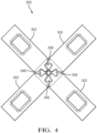
Fig. 4 is a front end view of a crimping tool having fixed limiting dies used to form the tubular ferrule of the conductor assembly ofFigs. 1 or; -
Fig. 5 is a close up front end view of the crimping dies and limiting dies of the crimping tool ofFig. 4 ; -
Fig. 6 is a perspective side view of the crimping tool ofFig. 4 with one of the crimping dies removed to better show the limiting dies; -
Fig. 7 is a front end view of a crimping tool having moveable limiting dies used to form the tubular ferrule of the conductor assembly ofFigs. 1 or3 ; -
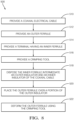
Fig. 8 is a flow chart of a method of manufacturing the conductor assemblies ofFigs. 1 or3 using the crimping tool ofFig. 4 orFig. 7 according to the invention. -
Fig. 9A is a perspective and end view of a tubular ferrule of the conductor assembly ofFigs. 1 and3 prior to forming with the crimping tool ofFig. 4 or7 ; and -
Fig. 9B is a perspective and end view of the tubular ferrule of the conductor assembly ofFig 9A after forming with the crimping tool ofFig. 4 or7 . - Claim 1 discloses a method of manufacturing a coaxial cable assembly according to the invention.
- Reference will now be made in detail to embodiments, examples of which are illustrated in the accompanying drawings. In the following detailed description, numerous specific details are set forth in order to provide a thorough understanding of the various described embodiments. However, it will be apparent to one of ordinary skill in the art that the various described embodiments may be practiced without these specific details. In other instances, well-known methods, procedures, components, circuits, and networks have not been described in detail so as not to unnecessarily obscure aspects of the embodiments.
- Presented herein is a conductor assembly that includes a seamless tubular ferrule that is crimped to an elongate conductor. The tubular ferrule is deformed in a crimping process to attach the ferrule to the conductor. After crimping, the ferrule defines four indentations having a consistent radius and four projections evenly spaced about a circumference of the ferrule. A tool used to deform the ferrule which limits the height four projections is also presented herein.
-
Figs. 1-3 illustrate a non-limiting example of aconductor assembly 100, hereinafter referred to as theassembly 100. As shown inFig. 3 , theassembly 100 includes an elongate conductor, in this particular example a coaxialelectrical cable 102. Thecoaxial cable 102 has a centralinner conductor 104, aninner insulator 106 surrounding theinner conductor 104, anouter conductor 108 surrounding theinner insulator 106, and anouter insulator 110 surrounding theouter conductor 108. As shown inFig. 2 , thecoaxial cable 102 has a generally circular cross section. - The
assembly 100 also includes a conductive inner terminal (not shown) connected to theinner conductor 104 and a conductiveouter terminal 112 surrounding the inner terminal and connected to theouter conductor 108. Theouter terminal 112 defines a tubularinner ferrule 114 that is disposed intermediate theinner insulator 106 and theouter insulator 110. According to the particular example illustrated inFig. 2 , theinner ferrule 114 is located intermediate theouter insulator 110 and theouter conductor 108. A terminal insulator is disposed between the inner terminal and theouter terminal 112. - The
assembly 100 further includes a generally cylindrical seamlessouter ferrule 116 having a surrounding a portion of theouter insulator 110 overlying theinner ferrule 114. Theouter ferrule 116 is deformed by acrimping tool 300 to define fourindentations 118 extending along theouter ferrule 116 in a direction generally parallel to the longitudinal axis X of theouter ferrule 116. Each of the fourindentations 118 have the sameconsistent indentation radius 122. The deformation produces fourprojections 120 extending along theouter ferrule 116 in a direction generally parallel to the longitudinal axis of theouter ferrule 116. The fourindentations 118 and the fourprojections 120 are evenly spaced about a circumference of theouter ferrule 116.Adjacent indentations 118 of the fourindentations 118 are spaced approximately 90 degrees apart about the longitudinal axis of theouter ferrule 116. As used herein, approximately 90 degrees apart is within a range of 80 to 100 degrees apart. As best shown inFig. 2 , one of the fourprojections 120 is located intermediate theadjacent indentations 118.Adjacent projections 120 of the fourprojections 120 are also spaced approximately 90 degrees apart about the longitudinal axis of theouter ferrule 116. As shown inFigs. 9A and 9B , theindentation radius 122 of the fourindentations 118 is less than theoriginal ferrule radius 124 of theouter ferrule 116 prior to deformation by thecrimping tool 300. - The
height 128 of each of the fourprojections 120 is controlled during thecrimping process 500 so that each of the fourprojections 120 is equal to or less than aheight threshold 130. Control of theprojection height 128 is discussed in more detail in the description of thecrimping tool 300 below. - As shown in
Fig. 1 , the fourindentations 118 and the fourprojections 120 extend along the entire length of theouter ferrule 116. According to an alternative embodiment of theassembly 200 shown inFig. 3 , only acentral portion 226 of theouter ferrule 216 is deformed to form the fourindentations 218 and the fourprojections 220. The ends of theouter ferrule 216 retain theoriginal ferrule radius 224. -
Figs 4-6 illustrate a non-limiting example of acrimping tool 300 used to crimp theouter ferrule Figs. 1 and3 . Thecrimping tool 300 is configured to form the four evenly spacedindentations projections outer ferrule 116. As shown inFig. 4 , thecrimping tool 300 includes fourcrimping dies 302. Each crimping die 302 of the fourcrimping dies 302 defines aconcave crimping surface 304 having anindentation radius 312 that is substantially equal to theindentation radius 122 of the formedouter ferrule 116. Thecrimping tool 300 also includes fourlimiting dies 306. As best shown inFig. 5 , each limiting die 306 defines a concavelimiting surface 308 having alimiting radius 310 that is greater than theindentation radius 312 of the crimping dies 302. Thelimiting dies 306 are configured to limit theheight 128 of each projection to the height threshold and are located intermediate twoadjacent crimping dies 302 of the fourcrimping dies 302. Adjacent crimping dies 302 are spaced approximately 90 degrees apart about a longitudinal axis of thecrimping tool 300. Adjacent limiting dies 306 of the fourlimiting dies 306 are also spaced approximately 90 degrees apart about the longitudinal axis of thecrimping tool 300. - Each limiting
surface 308 is spaced at a distance of the limitingradius 310 from the longitudinal axis of the ferrule. This limitingradius 310 is equal to theoriginal ferrule radius 124 plus the height threshold of the four protrusions of theouter ferrule 116. - According to the embodiment of the crimping
tool 300 shown inFig. 6 , the four limiting dies 306 are integrally formed in asingle die assembly 314 and are fixed such that each limitingsurface 308 remains at the distance of the limitingradius 310 as the four crimping dies 302 move relative to the longitudinal axis of thetool 300. - According to an alternative embodiment of the crimping
tool 400 shown inFig. 7 , the crimpingtool 400 further includes fourlinkages 410 between each crimping die 402 and an adjoining limitingdie 406. The fourlinkages 410 are configured to move each limiting die 406 and hence each limitingsurface 408 to the distance of the limitingradius 310 as the four crimping dies 402 move toward the longitudinal axis of thetool 400 as the crimpingtool 400 deforms theouter ferrule 116 of thecoaxial cable assembly 100. -
Fig. 8 describes amethod 500 of manufacturing thecoaxial cable assembly 100 according to the invention described above. Themethod 500 includes the following steps: -
STEP 510, PROVIDE A COAXIAL ELECTRICAL CABLE, includes providing a coaxialelectrical cable 102 comprising a centralinner conductor 104, aninner insulator 106 surrounding theinner conductor 104, anouter conductor 108 surrounding theinner insulator 106, and anouter insulator 110 surrounding theinner insulator 106; -
STEP 512, PROVIDE AN OUTER FERRULE, includes providing a generally cylindrical seamlessouter ferrule 116 having aferrule radius 124; -
STEP 514, PROVIDE A TERMINAL HAVING AN INNER FERRULE, is an optional step that includes providing a terminal 112 having aninner ferrule 114; -
STEP 516, PROVIDE A CRIMPING TOOL, includes providing a crimpingtool 300 including four crimping dies 302 each having adie face 304 defining aconsistent indentation radius 312 that is less than theferrule radius 124; -
STEP 518, DISPOSE THE INNER FERRULE INTERMEDIATE AN OUTER INSULATOR AND AN INNER INSULATOR OF THE COAXIAL CABLE, is an optional step that includes disposing theinner ferrule 114 intermediate theouter insulator 110 and theinner insulator 106 prior toSTEP 522, DEFORM THE OUTER FERRULE USING THE CRIMPING TOOL; -
STEP 520, PLACE THE OUTER FERRULE OVER A PORTION OF THE OUTER INSULATOR, includes placing theouter ferrule 116 over a portion of theouter insulator 110; and -
STEP 522, DEFORM THE OUTER FERRULE USING THE CRIMPING TOOL, includes deforming theouter ferrule 116 using the crimpingtool indentations 118 and fourprojections 120 in theouter ferrule 116 that are evenly spaced about a circumference of theouter ferrule 116. The outer ferrule is held between the four crimping dies so that the longitudinal axis of the outer ferrule is substantially coincident with the longitudinal axis of the crimping tool. The four crimping dies are brought simultaneously toward the longitudinal axes to provide substantially consistent pressure and deformation rates when forming the four indentations and the four projections. The fourindentations 118 each are characterized as having theindentation radius 122. - The four crimping dies 302 are spaced approximately 90 degrees apart about the longitudinal axis of the crimping tool. After deformation of the outer ferrule,
adjacent indentations 118 of the fourindentations 118 are spaced approximately 90 degrees apart about the longitudinal axis of theouter ferrule 116. One of the fourprojections 120 is located intermediate theadjacent indentations 118.Adjacent projections 120 of the fourprojections 120 are spaced approximately 90 degrees apart about the longitudinal axis of theouter ferrule 116. - Accordingly, a coaxial electrical cable assembly is provided. The consistent radius of the indentations and the limited height of the projections reduces the variation in capacitance between the inner and outer conductors of the coaxial cable in the area of the outer ferrule, thereby reducing the variation of impedance along the coaxial cable assembly which provides improved insertion loss performance. The outer ferrule, as formed with the four indentations and four projections, also provides improved retention of the outer ferrule and the outer terminal (by retention of the inner ferrule) to the assembly. The outer ferrule, as formed with the four indentations and four projections, is also more easily accommodated into existing connector body designs having generally cylindrical connector cavities in which the coaxial cable assembly is received.
- Accordingly, a crimping tool configured to form the four indentations and four projections in the outer ferrule is also provided. The tool includes four crimping dies to form the four indentations in the outer ferrule. The tool also inclines four limiting dies that limit growth of the four projections so that the four projections do not exceed a maximum height threshold. The crimping tool, when used with the outer ferrule, provides all of the benefits listed above.
- The example presented herein is directed to a coaxial electrical cable assembly, however other embodiments may be envisioned that are adapted for use with other types of shielded or unshielded electrical cables. Yet other embodiments of the assembly may be envisioned wherein the conductors are fiber optic cables, pneumatic tubes, or hydraulic tubes.
- While this invention has been described in terms of the preferred embodiments thereof, it is not intended to be so limited, but rather only to the extent set forth in the claims that follow. For example, the above-described embodiments (and/or aspects thereof) may be used in combination with each other. In addition, many modifications may be made to configure a particular situation or material to the teachings of the invention without departing from the scope of the claims.
Claims (3)
- A method (500) of manufacturing a coaxial cable assembly (100) comprising the steps of:providing (510) a coaxial electrical cable (102) comprising a central inner conductor (104), an inner insulator (106) surrounding the inner conductor (104), an outer conductor (108) surrounding the inner insulator (106), and an outer insulator (110) surrounding the inner insulator (106);providing (512) a generally cylindrical seamless outer ferrule (116) having a ferrule radius (124);providing (514) a terminal (112) having an inner ferrule (114) intermediate the outer insulator (110) and the inner insulator (106);providing (516) a crimping tool (300) including four crimping dies (302) each having a die face (304) defining a concave crimping surface (304) having a consistent indentation radius (312) that is substantially equal to an indentation radius (122) of the formed outer ferrule (116) and four limiting dies (306) defining a concave limiting surface (308) having a limiting radius (310) that is greater than the indentation radius (312) of the crimping dies (302) and located intermediate two adjacent crimping dies (302) of the four crimping dies (302);placing (520) the outer ferrule (116) over a portion of the outer insulator (110); anddeforming (522) the outer ferrule (116) using the crimping tool (300) to form four indentations (118) and four projections (120) in the outer ferrule (116) that are evenly spaced about a circumference of the outer ferrule (116), wherein the four indentations (118) each have the indentation radius (312) that is substantially equal to the consistent indentation radius (122) of the die face (304),wherein the limiting dies (306) are configured to limit the height (128) of each projection (120) to equal to or less than a height threshold (130) and are located intermediate two adjacent crimping dies (302) of the four crimping dies (302), wherein adjacent crimping dies (302) are spaced approximately 90 degrees apart about a longitudinal axis (X) of the crimping tool (300), and wherein adjacent limiting dies (306) of the four limiting dies (306) are also spaced approximately 90 degrees apart about the longitudinal axis (X) of the crimping tool (300).
- The method (500) according to claim 1, further comprising the steps of:
disposing (518) the inner ferrule (114) intermediate the outer insulator (110) and the inner insulator (106) prior to the step (522) of deforming the outer ferrule (116). - The method (500) according to any of claims 1-2, wherein a portion of the outer ferrule (116) retains the ferrule radius (124) after deformation.
Priority Applications (1)
| Application Number | Priority Date | Filing Date | Title |
|---|---|---|---|
| EP23180823.9A EP4243223A3 (en) | 2018-03-26 | 2019-03-04 | Method of manufacturing a conductor assembly with a crimped tubular ferrule |
Applications Claiming Priority (1)
| Application Number | Priority Date | Filing Date | Title |
|---|---|---|---|
| US15/935,375 US10355379B1 (en) | 2018-03-26 | 2018-03-26 | Conductor assembly with a crimped tubular ferrule and method of manufacturing same |
Related Child Applications (1)
| Application Number | Title | Priority Date | Filing Date |
|---|---|---|---|
| EP23180823.9A Division EP4243223A3 (en) | 2018-03-26 | 2019-03-04 | Method of manufacturing a conductor assembly with a crimped tubular ferrule |
Publications (2)
| Publication Number | Publication Date |
|---|---|
| EP3547454A1 EP3547454A1 (en) | 2019-10-02 |
| EP3547454B1 true EP3547454B1 (en) | 2023-07-19 |
Family
ID=65685218
Family Applications (2)
| Application Number | Title | Priority Date | Filing Date |
|---|---|---|---|
| EP23180823.9A Pending EP4243223A3 (en) | 2018-03-26 | 2019-03-04 | Method of manufacturing a conductor assembly with a crimped tubular ferrule |
| EP19160458.6A Active EP3547454B1 (en) | 2018-03-26 | 2019-03-04 | Method of manufacturing a conductor assembly with a crimped tubular ferrule |
Family Applications Before (1)
| Application Number | Title | Priority Date | Filing Date |
|---|---|---|---|
| EP23180823.9A Pending EP4243223A3 (en) | 2018-03-26 | 2019-03-04 | Method of manufacturing a conductor assembly with a crimped tubular ferrule |
Country Status (5)
| Country | Link |
|---|---|
| US (1) | US10355379B1 (en) |
| EP (2) | EP4243223A3 (en) |
| JP (1) | JP6735869B2 (en) |
| KR (1) | KR102139883B1 (en) |
| CN (1) | CN110364832B (en) |
Families Citing this family (6)
| Publication number | Priority date | Publication date | Assignee | Title |
|---|---|---|---|---|
| US10916893B2 (en) * | 2019-06-25 | 2021-02-09 | Itt Manufacturing Enterprises Llc | Crosstalk shield |
| CN110661154B (en) * | 2019-08-30 | 2020-08-18 | 安波福连接器系统(南通)有限公司 | Cutter assembly for manufacturing electric terminal |
| EP3840125B1 (en) * | 2019-12-18 | 2023-10-11 | MD Elektronik GmbH | Method and device for producing a cable assembly |
| JP7197544B2 (en) * | 2020-09-28 | 2022-12-27 | 矢崎総業株式会社 | Shielded wire manufacturing method, shielded wire with grounding member, and crimping device |
| JP2023122883A (en) * | 2022-02-24 | 2023-09-05 | 住友電装株式会社 | Shield wire and manufacturing device for the same |
| FR3148873B1 (en) * | 2023-05-19 | 2025-05-23 | Safran Electrical Components | Circular crimping die and crimping process |
Family Cites Families (7)
| Publication number | Priority date | Publication date | Assignee | Title |
|---|---|---|---|---|
| US2226849A (en) * | 1936-07-03 | 1940-12-31 | Kingston Products Corp | Electrical connection means |
| US3234776A (en) * | 1963-09-04 | 1966-02-15 | Amp Inc | Crimping device |
| US4890384A (en) * | 1988-08-25 | 1990-01-02 | Amp Incorporated | Method of crimping an electrical connection |
| JP2011171057A (en) * | 2010-02-17 | 2011-09-01 | Yazaki Corp | Crimping apparatus for shielded wire, and method for end-processing shielded wire |
| US8366483B2 (en) * | 2011-02-04 | 2013-02-05 | Tyco Electronics Corporation | Radio frequency connector assembly |
| US8827744B2 (en) * | 2011-07-29 | 2014-09-09 | Delphi Technologies, Inc. | Wire cable assembly |
| DE202015000751U1 (en) * | 2015-01-30 | 2015-03-06 | Rosenberger Hochfrequenztechnik Gmbh & Co. Kg | Connector assembly with compensation crimp |
-
2018
- 2018-03-26 US US15/935,375 patent/US10355379B1/en active Active
-
2019
- 2019-03-04 EP EP23180823.9A patent/EP4243223A3/en active Pending
- 2019-03-04 EP EP19160458.6A patent/EP3547454B1/en active Active
- 2019-03-21 KR KR1020190032332A patent/KR102139883B1/en active Active
- 2019-03-22 JP JP2019054088A patent/JP6735869B2/en active Active
- 2019-03-26 CN CN201910231872.1A patent/CN110364832B/en active Active
Also Published As
| Publication number | Publication date |
|---|---|
| EP3547454A1 (en) | 2019-10-02 |
| KR20190112657A (en) | 2019-10-07 |
| KR102139883B1 (en) | 2020-07-31 |
| US10355379B1 (en) | 2019-07-16 |
| CN110364832A (en) | 2019-10-22 |
| EP4243223A3 (en) | 2023-11-15 |
| EP4243223A2 (en) | 2023-09-13 |
| CN110364832B (en) | 2021-12-07 |
| JP6735869B2 (en) | 2020-08-05 |
| JP2019175845A (en) | 2019-10-10 |
Similar Documents
| Publication | Publication Date | Title |
|---|---|---|
| US10355379B1 (en) | Conductor assembly with a crimped tubular ferrule and method of manufacturing same | |
| EP3569326B1 (en) | Ferrule crimping tool | |
| EP0083464B1 (en) | Coaxial cable with a connector | |
| CN107210544B (en) | Plug connector assembly with compensating crimp | |
| US9960565B2 (en) | Method and device for producing an operative connection between a connector and a cable | |
| JP4082710B2 (en) | connector | |
| EP3518353A1 (en) | Method for producing a modularly configurable coaxial plug | |
| US10361496B1 (en) | Conductor assembly with a crimped tubular ferrule and method and tool for manufacturing same | |
| US3537167A (en) | Preform cold-crimp sleeve applicator | |
| EP2037538A2 (en) | 90-Degree ferrule and pin terminals | |
| US4345373A (en) | Method of manufacture of low-cost, high quality low insertion force electrical connector socket | |
| EP0026117B1 (en) | Electrical contact for an electrical connector and method of making same | |
| EP3588680B1 (en) | Conductor assembly with a crimped tubular ferrule and method and tool for manufacturing same | |
| US8272901B2 (en) | Crimp contacts and electrical connector assemblies including the same | |
| US11349241B2 (en) | Power socket for electrical connector system | |
| CA1113168A (en) | Low-cost, high quality low insertion force electrical connector and method of manufacture | |
| TW202508166A (en) | Method for producing an assembly of a connector and a coaxial cable, and assembly | |
| KR20140037960A (en) | Terminal and manufacturing method of terminal |
Legal Events
| Date | Code | Title | Description |
|---|---|---|---|
| PUAI | Public reference made under article 153(3) epc to a published international application that has entered the european phase |
Free format text: ORIGINAL CODE: 0009012 |
|
| STAA | Information on the status of an ep patent application or granted ep patent |
Free format text: STATUS: THE APPLICATION HAS BEEN PUBLISHED |
|
| AK | Designated contracting states |
Kind code of ref document: A1 Designated state(s): AL AT BE BG CH CY CZ DE DK EE ES FI FR GB GR HR HU IE IS IT LI LT LU LV MC MK MT NL NO PL PT RO RS SE SI SK SM TR |
|
| AX | Request for extension of the european patent |
Extension state: BA ME |
|
| STAA | Information on the status of an ep patent application or granted ep patent |
Free format text: STATUS: REQUEST FOR EXAMINATION WAS MADE |
|
| 17P | Request for examination filed |
Effective date: 20200331 |
|
| RBV | Designated contracting states (corrected) |
Designated state(s): AL AT BE BG CH CY CZ DE DK EE ES FI FR GB GR HR HU IE IS IT LI LT LU LV MC MK MT NL NO PL PT RO RS SE SI SK SM TR |
|
| STAA | Information on the status of an ep patent application or granted ep patent |
Free format text: STATUS: EXAMINATION IS IN PROGRESS |
|
| 17Q | First examination report despatched |
Effective date: 20201214 |
|
| RIC1 | Information provided on ipc code assigned before grant |
Ipc: H01R 4/20 20060101AFI20210712BHEP Ipc: H01R 4/18 20060101ALI20210712BHEP Ipc: H01R 43/048 20060101ALI20210712BHEP Ipc: H01R 9/05 20060101ALI20210712BHEP Ipc: H01R 43/058 20060101ALN20210712BHEP Ipc: B21D 39/04 20060101ALN20210712BHEP |
|
| RIC1 | Information provided on ipc code assigned before grant |
Ipc: H01R 4/20 20060101AFI20210719BHEP Ipc: H01R 4/18 20060101ALI20210719BHEP Ipc: H01R 43/048 20060101ALI20210719BHEP Ipc: H01R 9/05 20060101ALI20210719BHEP Ipc: H01R 43/058 20060101ALI20210719BHEP Ipc: B21D 39/04 20060101ALN20210719BHEP |
|
| RIC1 | Information provided on ipc code assigned before grant |
Ipc: B21D 39/04 20060101ALN20210901BHEP Ipc: H01R 43/058 20060101ALI20210901BHEP Ipc: H01R 9/05 20060101ALI20210901BHEP Ipc: H01R 43/048 20060101ALI20210901BHEP Ipc: H01R 4/18 20060101ALI20210901BHEP Ipc: H01R 4/20 20060101AFI20210901BHEP |
|
| RAP3 | Party data changed (applicant data changed or rights of an application transferred) |
Owner name: APTIV TECHNOLOGIES LIMITED |
|
| GRAP | Despatch of communication of intention to grant a patent |
Free format text: ORIGINAL CODE: EPIDOSNIGR1 |
|
| STAA | Information on the status of an ep patent application or granted ep patent |
Free format text: STATUS: GRANT OF PATENT IS INTENDED |
|
| RIC1 | Information provided on ipc code assigned before grant |
Ipc: B21D 39/04 20060101ALN20230414BHEP Ipc: H01R 43/058 20060101ALI20230414BHEP Ipc: H01R 9/05 20060101ALI20230414BHEP Ipc: H01R 43/048 20060101ALI20230414BHEP Ipc: H01R 4/18 20060101ALI20230414BHEP Ipc: H01R 4/20 20060101AFI20230414BHEP |
|
| INTG | Intention to grant announced |
Effective date: 20230504 |
|
| GRAS | Grant fee paid |
Free format text: ORIGINAL CODE: EPIDOSNIGR3 |
|
| GRAA | (expected) grant |
Free format text: ORIGINAL CODE: 0009210 |
|
| STAA | Information on the status of an ep patent application or granted ep patent |
Free format text: STATUS: THE PATENT HAS BEEN GRANTED |
|
| AK | Designated contracting states |
Kind code of ref document: B1 Designated state(s): AL AT BE BG CH CY CZ DE DK EE ES FI FR GB GR HR HU IE IS IT LI LT LU LV MC MK MT NL NO PL PT RO RS SE SI SK SM TR |
|
| P01 | Opt-out of the competence of the unified patent court (upc) registered |
Effective date: 20230612 |
|
| REG | Reference to a national code |
Ref country code: GB Ref legal event code: FG4D |
|
| REG | Reference to a national code |
Ref country code: CH Ref legal event code: EP |
|
| REG | Reference to a national code |
Ref country code: DE Ref legal event code: R096 Ref document number: 602019032851 Country of ref document: DE |
|
| REG | Reference to a national code |
Ref country code: IE Ref legal event code: FG4D |
|
| REG | Reference to a national code |
Ref country code: LT Ref legal event code: MG9D |
|
| REG | Reference to a national code |
Ref country code: NL Ref legal event code: MP Effective date: 20230719 |
|
| REG | Reference to a national code |
Ref country code: AT Ref legal event code: MK05 Ref document number: 1590421 Country of ref document: AT Kind code of ref document: T Effective date: 20230719 |
|
| PG25 | Lapsed in a contracting state [announced via postgrant information from national office to epo] |
Ref country code: NL Free format text: LAPSE BECAUSE OF FAILURE TO SUBMIT A TRANSLATION OF THE DESCRIPTION OR TO PAY THE FEE WITHIN THE PRESCRIBED TIME-LIMIT Effective date: 20230719 |
|
| PG25 | Lapsed in a contracting state [announced via postgrant information from national office to epo] |
Ref country code: GR Free format text: LAPSE BECAUSE OF FAILURE TO SUBMIT A TRANSLATION OF THE DESCRIPTION OR TO PAY THE FEE WITHIN THE PRESCRIBED TIME-LIMIT Effective date: 20231020 |
|
| PG25 | Lapsed in a contracting state [announced via postgrant information from national office to epo] |
Ref country code: IS Free format text: LAPSE BECAUSE OF FAILURE TO SUBMIT A TRANSLATION OF THE DESCRIPTION OR TO PAY THE FEE WITHIN THE PRESCRIBED TIME-LIMIT Effective date: 20231119 |
|
| PG25 | Lapsed in a contracting state [announced via postgrant information from national office to epo] |
Ref country code: SE Free format text: LAPSE BECAUSE OF FAILURE TO SUBMIT A TRANSLATION OF THE DESCRIPTION OR TO PAY THE FEE WITHIN THE PRESCRIBED TIME-LIMIT Effective date: 20230719 Ref country code: RS Free format text: LAPSE BECAUSE OF FAILURE TO SUBMIT A TRANSLATION OF THE DESCRIPTION OR TO PAY THE FEE WITHIN THE PRESCRIBED TIME-LIMIT Effective date: 20230719 Ref country code: PT Free format text: LAPSE BECAUSE OF FAILURE TO SUBMIT A TRANSLATION OF THE DESCRIPTION OR TO PAY THE FEE WITHIN THE PRESCRIBED TIME-LIMIT Effective date: 20231120 Ref country code: NO Free format text: LAPSE BECAUSE OF FAILURE TO SUBMIT A TRANSLATION OF THE DESCRIPTION OR TO PAY THE FEE WITHIN THE PRESCRIBED TIME-LIMIT Effective date: 20231019 Ref country code: LV Free format text: LAPSE BECAUSE OF FAILURE TO SUBMIT A TRANSLATION OF THE DESCRIPTION OR TO PAY THE FEE WITHIN THE PRESCRIBED TIME-LIMIT Effective date: 20230719 Ref country code: LT Free format text: LAPSE BECAUSE OF FAILURE TO SUBMIT A TRANSLATION OF THE DESCRIPTION OR TO PAY THE FEE WITHIN THE PRESCRIBED TIME-LIMIT Effective date: 20230719 Ref country code: IS Free format text: LAPSE BECAUSE OF FAILURE TO SUBMIT A TRANSLATION OF THE DESCRIPTION OR TO PAY THE FEE WITHIN THE PRESCRIBED TIME-LIMIT Effective date: 20231119 Ref country code: HR Free format text: LAPSE BECAUSE OF FAILURE TO SUBMIT A TRANSLATION OF THE DESCRIPTION OR TO PAY THE FEE WITHIN THE PRESCRIBED TIME-LIMIT Effective date: 20230719 Ref country code: GR Free format text: LAPSE BECAUSE OF FAILURE TO SUBMIT A TRANSLATION OF THE DESCRIPTION OR TO PAY THE FEE WITHIN THE PRESCRIBED TIME-LIMIT Effective date: 20231020 Ref country code: FI Free format text: LAPSE BECAUSE OF FAILURE TO SUBMIT A TRANSLATION OF THE DESCRIPTION OR TO PAY THE FEE WITHIN THE PRESCRIBED TIME-LIMIT Effective date: 20230719 Ref country code: AT Free format text: LAPSE BECAUSE OF FAILURE TO SUBMIT A TRANSLATION OF THE DESCRIPTION OR TO PAY THE FEE WITHIN THE PRESCRIBED TIME-LIMIT Effective date: 20230719 |
|
| PG25 | Lapsed in a contracting state [announced via postgrant information from national office to epo] |
Ref country code: PL Free format text: LAPSE BECAUSE OF FAILURE TO SUBMIT A TRANSLATION OF THE DESCRIPTION OR TO PAY THE FEE WITHIN THE PRESCRIBED TIME-LIMIT Effective date: 20230719 |
|
| REG | Reference to a national code |
Ref country code: DE Ref legal event code: R097 Ref document number: 602019032851 Country of ref document: DE |
|
| PG25 | Lapsed in a contracting state [announced via postgrant information from national office to epo] |
Ref country code: ES Free format text: LAPSE BECAUSE OF FAILURE TO SUBMIT A TRANSLATION OF THE DESCRIPTION OR TO PAY THE FEE WITHIN THE PRESCRIBED TIME-LIMIT Effective date: 20230719 |
|
| PG25 | Lapsed in a contracting state [announced via postgrant information from national office to epo] |
Ref country code: SM Free format text: LAPSE BECAUSE OF FAILURE TO SUBMIT A TRANSLATION OF THE DESCRIPTION OR TO PAY THE FEE WITHIN THE PRESCRIBED TIME-LIMIT Effective date: 20230719 Ref country code: RO Free format text: LAPSE BECAUSE OF FAILURE TO SUBMIT A TRANSLATION OF THE DESCRIPTION OR TO PAY THE FEE WITHIN THE PRESCRIBED TIME-LIMIT Effective date: 20230719 Ref country code: ES Free format text: LAPSE BECAUSE OF FAILURE TO SUBMIT A TRANSLATION OF THE DESCRIPTION OR TO PAY THE FEE WITHIN THE PRESCRIBED TIME-LIMIT Effective date: 20230719 Ref country code: EE Free format text: LAPSE BECAUSE OF FAILURE TO SUBMIT A TRANSLATION OF THE DESCRIPTION OR TO PAY THE FEE WITHIN THE PRESCRIBED TIME-LIMIT Effective date: 20230719 Ref country code: DK Free format text: LAPSE BECAUSE OF FAILURE TO SUBMIT A TRANSLATION OF THE DESCRIPTION OR TO PAY THE FEE WITHIN THE PRESCRIBED TIME-LIMIT Effective date: 20230719 Ref country code: CZ Free format text: LAPSE BECAUSE OF FAILURE TO SUBMIT A TRANSLATION OF THE DESCRIPTION OR TO PAY THE FEE WITHIN THE PRESCRIBED TIME-LIMIT Effective date: 20230719 Ref country code: SK Free format text: LAPSE BECAUSE OF FAILURE TO SUBMIT A TRANSLATION OF THE DESCRIPTION OR TO PAY THE FEE WITHIN THE PRESCRIBED TIME-LIMIT Effective date: 20230719 |
|
| PLBE | No opposition filed within time limit |
Free format text: ORIGINAL CODE: 0009261 |
|
| STAA | Information on the status of an ep patent application or granted ep patent |
Free format text: STATUS: NO OPPOSITION FILED WITHIN TIME LIMIT |
|
| PG25 | Lapsed in a contracting state [announced via postgrant information from national office to epo] |
Ref country code: IT Free format text: LAPSE BECAUSE OF FAILURE TO SUBMIT A TRANSLATION OF THE DESCRIPTION OR TO PAY THE FEE WITHIN THE PRESCRIBED TIME-LIMIT Effective date: 20230719 |
|
| 26N | No opposition filed |
Effective date: 20240422 |
|
| PG25 | Lapsed in a contracting state [announced via postgrant information from national office to epo] |
Ref country code: SI Free format text: LAPSE BECAUSE OF FAILURE TO SUBMIT A TRANSLATION OF THE DESCRIPTION OR TO PAY THE FEE WITHIN THE PRESCRIBED TIME-LIMIT Effective date: 20230719 |
|
| REG | Reference to a national code |
Ref country code: CH Ref legal event code: PL |
|
| PG25 | Lapsed in a contracting state [announced via postgrant information from national office to epo] |
Ref country code: BG Free format text: LAPSE BECAUSE OF FAILURE TO SUBMIT A TRANSLATION OF THE DESCRIPTION OR TO PAY THE FEE WITHIN THE PRESCRIBED TIME-LIMIT Effective date: 20230719 |
|
| PG25 | Lapsed in a contracting state [announced via postgrant information from national office to epo] |
Ref country code: LU Free format text: LAPSE BECAUSE OF NON-PAYMENT OF DUE FEES Effective date: 20240304 |
|
| PG25 | Lapsed in a contracting state [announced via postgrant information from national office to epo] |
Ref country code: MC Free format text: LAPSE BECAUSE OF FAILURE TO SUBMIT A TRANSLATION OF THE DESCRIPTION OR TO PAY THE FEE WITHIN THE PRESCRIBED TIME-LIMIT Effective date: 20230719 |
|
| PG25 | Lapsed in a contracting state [announced via postgrant information from national office to epo] |
Ref country code: MC Free format text: LAPSE BECAUSE OF FAILURE TO SUBMIT A TRANSLATION OF THE DESCRIPTION OR TO PAY THE FEE WITHIN THE PRESCRIBED TIME-LIMIT Effective date: 20230719 Ref country code: LU Free format text: LAPSE BECAUSE OF NON-PAYMENT OF DUE FEES Effective date: 20240304 Ref country code: BG Free format text: LAPSE BECAUSE OF FAILURE TO SUBMIT A TRANSLATION OF THE DESCRIPTION OR TO PAY THE FEE WITHIN THE PRESCRIBED TIME-LIMIT Effective date: 20230719 |
|
| REG | Reference to a national code |
Ref country code: BE Ref legal event code: MM Effective date: 20240331 |
|
| PG25 | Lapsed in a contracting state [announced via postgrant information from national office to epo] |
Ref country code: BE Free format text: LAPSE BECAUSE OF NON-PAYMENT OF DUE FEES Effective date: 20240331 |
|
| PG25 | Lapsed in a contracting state [announced via postgrant information from national office to epo] |
Ref country code: IE Free format text: LAPSE BECAUSE OF NON-PAYMENT OF DUE FEES Effective date: 20240304 |
|
| PG25 | Lapsed in a contracting state [announced via postgrant information from national office to epo] |
Ref country code: IE Free format text: LAPSE BECAUSE OF NON-PAYMENT OF DUE FEES Effective date: 20240304 Ref country code: BE Free format text: LAPSE BECAUSE OF NON-PAYMENT OF DUE FEES Effective date: 20240331 Ref country code: CH Free format text: LAPSE BECAUSE OF NON-PAYMENT OF DUE FEES Effective date: 20240331 |
|
| REG | Reference to a national code |
Ref country code: DE Ref legal event code: R081 Ref document number: 602019032851 Country of ref document: DE Owner name: APTIV TECHNOLOGIES AG, CH Free format text: FORMER OWNER: APTIV TECHNOLOGIES LIMITED, ST. MICHAEL, BB |
|
| PG25 | Lapsed in a contracting state [announced via postgrant information from national office to epo] |
Ref country code: CY Free format text: LAPSE BECAUSE OF FAILURE TO SUBMIT A TRANSLATION OF THE DESCRIPTION OR TO PAY THE FEE WITHIN THE PRESCRIBED TIME-LIMIT; INVALID AB INITIO Effective date: 20190304 |
|
| PG25 | Lapsed in a contracting state [announced via postgrant information from national office to epo] |
Ref country code: HU Free format text: LAPSE BECAUSE OF FAILURE TO SUBMIT A TRANSLATION OF THE DESCRIPTION OR TO PAY THE FEE WITHIN THE PRESCRIBED TIME-LIMIT; INVALID AB INITIO Effective date: 20190304 |
|
| PG25 | Lapsed in a contracting state [announced via postgrant information from national office to epo] |
Ref country code: TR Free format text: LAPSE BECAUSE OF FAILURE TO SUBMIT A TRANSLATION OF THE DESCRIPTION OR TO PAY THE FEE WITHIN THE PRESCRIBED TIME-LIMIT Effective date: 20230719 |
|
| PGFP | Annual fee paid to national office [announced via postgrant information from national office to epo] |
Ref country code: GB Payment date: 20260204 Year of fee payment: 8 |
|
| PGFP | Annual fee paid to national office [announced via postgrant information from national office to epo] |
Ref country code: DE Payment date: 20260223 Year of fee payment: 8 |
|
| PGFP | Annual fee paid to national office [announced via postgrant information from national office to epo] |
Ref country code: FR Payment date: 20260205 Year of fee payment: 8 |