EP3547392A1 - Secondary battery - Google Patents
Secondary battery Download PDFInfo
- Publication number
- EP3547392A1 EP3547392A1 EP17873498.4A EP17873498A EP3547392A1 EP 3547392 A1 EP3547392 A1 EP 3547392A1 EP 17873498 A EP17873498 A EP 17873498A EP 3547392 A1 EP3547392 A1 EP 3547392A1
- Authority
- EP
- European Patent Office
- Prior art keywords
- case
- electrode
- secondary battery
- conductive cover
- cap
- Prior art date
- Legal status (The legal status is an assumption and is not a legal conclusion. Google has not performed a legal analysis and makes no representation as to the accuracy of the status listed.)
- Granted
Links
Images


Classifications
-
- H—ELECTRICITY
- H01—ELECTRIC ELEMENTS
- H01M—PROCESSES OR MEANS, e.g. BATTERIES, FOR THE DIRECT CONVERSION OF CHEMICAL ENERGY INTO ELECTRICAL ENERGY
- H01M50/00—Constructional details or processes of manufacture of the non-active parts of electrochemical cells other than fuel cells, e.g. hybrid cells
- H01M50/50—Current conducting connections for cells or batteries
- H01M50/543—Terminals
- H01M50/547—Terminals characterised by the disposition of the terminals on the cells
- H01M50/55—Terminals characterised by the disposition of the terminals on the cells on the same side of the cell
-
- H—ELECTRICITY
- H01—ELECTRIC ELEMENTS
- H01M—PROCESSES OR MEANS, e.g. BATTERIES, FOR THE DIRECT CONVERSION OF CHEMICAL ENERGY INTO ELECTRICAL ENERGY
- H01M10/00—Secondary cells; Manufacture thereof
- H01M10/05—Accumulators with non-aqueous electrolyte
- H01M10/058—Construction or manufacture
-
- H—ELECTRICITY
- H01—ELECTRIC ELEMENTS
- H01M—PROCESSES OR MEANS, e.g. BATTERIES, FOR THE DIRECT CONVERSION OF CHEMICAL ENERGY INTO ELECTRICAL ENERGY
- H01M50/00—Constructional details or processes of manufacture of the non-active parts of electrochemical cells other than fuel cells, e.g. hybrid cells
- H01M50/10—Primary casings; Jackets or wrappings
- H01M50/147—Lids or covers
- H01M50/148—Lids or covers characterised by their shape
- H01M50/152—Lids or covers characterised by their shape for cells having curved cross-section, e.g. round or elliptic
-
- H—ELECTRICITY
- H01—ELECTRIC ELEMENTS
- H01M—PROCESSES OR MEANS, e.g. BATTERIES, FOR THE DIRECT CONVERSION OF CHEMICAL ENERGY INTO ELECTRICAL ENERGY
- H01M50/00—Constructional details or processes of manufacture of the non-active parts of electrochemical cells other than fuel cells, e.g. hybrid cells
- H01M50/10—Primary casings; Jackets or wrappings
- H01M50/102—Primary casings; Jackets or wrappings characterised by their shape or physical structure
- H01M50/107—Primary casings; Jackets or wrappings characterised by their shape or physical structure having curved cross-section, e.g. round or elliptic
-
- H—ELECTRICITY
- H01—ELECTRIC ELEMENTS
- H01M—PROCESSES OR MEANS, e.g. BATTERIES, FOR THE DIRECT CONVERSION OF CHEMICAL ENERGY INTO ELECTRICAL ENERGY
- H01M50/00—Constructional details or processes of manufacture of the non-active parts of electrochemical cells other than fuel cells, e.g. hybrid cells
- H01M50/10—Primary casings; Jackets or wrappings
- H01M50/147—Lids or covers
- H01M50/155—Lids or covers characterised by the material
- H01M50/157—Inorganic material
- H01M50/159—Metals
-
- H—ELECTRICITY
- H01—ELECTRIC ELEMENTS
- H01M—PROCESSES OR MEANS, e.g. BATTERIES, FOR THE DIRECT CONVERSION OF CHEMICAL ENERGY INTO ELECTRICAL ENERGY
- H01M50/00—Constructional details or processes of manufacture of the non-active parts of electrochemical cells other than fuel cells, e.g. hybrid cells
- H01M50/10—Primary casings; Jackets or wrappings
- H01M50/172—Arrangements of electric connectors penetrating the casing
- H01M50/174—Arrangements of electric connectors penetrating the casing adapted for the shape of the cells
- H01M50/179—Arrangements of electric connectors penetrating the casing adapted for the shape of the cells for cells having curved cross-section, e.g. round or elliptic
-
- H—ELECTRICITY
- H01—ELECTRIC ELEMENTS
- H01M—PROCESSES OR MEANS, e.g. BATTERIES, FOR THE DIRECT CONVERSION OF CHEMICAL ENERGY INTO ELECTRICAL ENERGY
- H01M50/00—Constructional details or processes of manufacture of the non-active parts of electrochemical cells other than fuel cells, e.g. hybrid cells
- H01M50/50—Current conducting connections for cells or batteries
- H01M50/531—Electrode connections inside a battery casing
- H01M50/536—Electrode connections inside a battery casing characterised by the method of fixing the leads to the electrodes, e.g. by welding
-
- H—ELECTRICITY
- H01—ELECTRIC ELEMENTS
- H01M—PROCESSES OR MEANS, e.g. BATTERIES, FOR THE DIRECT CONVERSION OF CHEMICAL ENERGY INTO ELECTRICAL ENERGY
- H01M50/00—Constructional details or processes of manufacture of the non-active parts of electrochemical cells other than fuel cells, e.g. hybrid cells
- H01M50/50—Current conducting connections for cells or batteries
- H01M50/543—Terminals
- H01M50/547—Terminals characterised by the disposition of the terminals on the cells
- H01M50/548—Terminals characterised by the disposition of the terminals on the cells on opposite sides of the cell
-
- H—ELECTRICITY
- H01—ELECTRIC ELEMENTS
- H01M—PROCESSES OR MEANS, e.g. BATTERIES, FOR THE DIRECT CONVERSION OF CHEMICAL ENERGY INTO ELECTRICAL ENERGY
- H01M50/00—Constructional details or processes of manufacture of the non-active parts of electrochemical cells other than fuel cells, e.g. hybrid cells
- H01M50/50—Current conducting connections for cells or batteries
- H01M50/543—Terminals
- H01M50/552—Terminals characterised by their shape
- H01M50/559—Terminals adapted for cells having curved cross-section, e.g. round, elliptic or button cells
-
- Y—GENERAL TAGGING OF NEW TECHNOLOGICAL DEVELOPMENTS; GENERAL TAGGING OF CROSS-SECTIONAL TECHNOLOGIES SPANNING OVER SEVERAL SECTIONS OF THE IPC; TECHNICAL SUBJECTS COVERED BY FORMER USPC CROSS-REFERENCE ART COLLECTIONS [XRACs] AND DIGESTS
- Y02—TECHNOLOGIES OR APPLICATIONS FOR MITIGATION OR ADAPTATION AGAINST CLIMATE CHANGE
- Y02E—REDUCTION OF GREENHOUSE GAS [GHG] EMISSIONS, RELATED TO ENERGY GENERATION, TRANSMISSION OR DISTRIBUTION
- Y02E60/00—Enabling technologies; Technologies with a potential or indirect contribution to GHG emissions mitigation
- Y02E60/10—Energy storage using batteries
-
- Y—GENERAL TAGGING OF NEW TECHNOLOGICAL DEVELOPMENTS; GENERAL TAGGING OF CROSS-SECTIONAL TECHNOLOGIES SPANNING OVER SEVERAL SECTIONS OF THE IPC; TECHNICAL SUBJECTS COVERED BY FORMER USPC CROSS-REFERENCE ART COLLECTIONS [XRACs] AND DIGESTS
- Y02—TECHNOLOGIES OR APPLICATIONS FOR MITIGATION OR ADAPTATION AGAINST CLIMATE CHANGE
- Y02P—CLIMATE CHANGE MITIGATION TECHNOLOGIES IN THE PRODUCTION OR PROCESSING OF GOODS
- Y02P70/00—Climate change mitigation technologies in the production process for final industrial or consumer products
- Y02P70/50—Manufacturing or production processes characterised by the final manufactured product
Definitions
- the present invention relates to a secondary battery.
- a cylindrical secondary battery is configured such that electrode tabs are welded to its opposite sides (top and bottom portions) to draw positive and negative electrodes to the outside, respectively.
- the electrode tabs are drawn out from the opposite sides, there is spatial limitation.
- the positive electrode tab is welded to a cap-up
- the negative electrode tab is welded to a top end of a case, thereby drawing both of the positive and negative electrode tabs from the top end of the secondary battery.
- a round beading part for fixing the electrode assembly with a gasket is formed at the top end of the case in the course of forming the case. Accordingly, it is difficult to weld the electrode tab to the round beading part.
- the present invention provides a secondary battery, which can facilitate welding of an electrode tab and can maximize space utilization by forming a conductive cover electrically connected to a case and having a flat part at an upper part of the case.
- a secondary battery including: an electrode assembly; a case for accommodating the electrode assembly; a cap assembly which is coupled to an upper part of the case so as to seal the case, and has a terminal part; and a conductive cover which is coupled to an upper part of the case and fixed to a lateral plate of the case.
- the conductive cover may include: a flat part covering the upper part of the case and flatly formed; an extending part downwardly extending from the flat part; and a coupling part inwardly protruding from the extending part and contacting the lateral plate of the case.
- a hole exposing the terminal part to the outside may be formed in the flat part.
- the hole may have a larger diameter than the terminal part.
- the coupling part may include a first region contacting the lateral plate of the case, and a second region positioned at opposite side of the first region and connecting the first region to the extending part.
- the conductive cover may further include an electrode tab formed by cutting a portion of the flat part and bending the cut portion.
- the conductive cover may further include an electrode tab formed by cutting a portion of the extending part and bending the cut portion.
- the electrode assembly may include a first electrode, a second electrode and a separator interposed between the first electrode and the second electrode, wherein the terminal part is electrically connected to the first electrode, and the conductive cover is electrically connected to the second electrode.
- the secondary battery may further include an insulation member positioned between the case and the flat part and having a hole exposing the terminal part.
- the insulation member may include an insulating adhesive tape.
- a conductive cover electrically connected to a case and having a flat part is formed at a top end of the case, thereby facilitating welding an electrode tab to the flat part.
- electrode tabs electrically connected to a first electrode and a second electrode in a cylindrical secondary battery, respectively are both drawn out to one side, space utilization can be maximized.
- FIG. 1 is a perspective view of a secondary battery according to an embodiment of the present invention.
- FIG. 2 is an exploded perspective view of the secondary battery according to an embodiment of the present invention.
- FIG. 3 is a cross-sectional view of the secondary battery according to an embodiment of the present invention.
- FIG. 4 is a perspective view of a conductive cover shown in FIG. 1 .
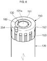
- FIGS. 5 and 6 are perspective views of a variety of electrode tabs positioned on the conductive cover according to an embodiment of the present invention.
- the secondary battery 100 includes an electrode assembly 110, a case 120 accommodating the electrode assembly 110, a cap assembly 130 coupled to a top opening of the case 120, a gasket 140 allowing the case 120 and the cap assembly 130 to be tightly contacted with each other, a conductive cover 150 coupled to an upper part of the case 120 and the cap assembly 130, and an insulation member 160 positioned between the upper part of the case 120 and the conductive cover 150.
- the electrode assembly 110 includes a first electrode 111, a second electrode 112, and a separator 113 interposed between the first electrode 111 and the second electrode 112.
- the electrode assembly 110 may be formed by winding a stacked structure of the first electrode 111, the separator 113 and the second electrode 112 in a jelly-roll configuration.
- the first electrode 111 may function as a positive electrode
- the second electrode 112 may function as a negative electrode.
- a first electrode tab 114 is connected to the cap assembly 130 at an upper part of the electrode assembly 110
- a second electrode tab 115 is connected to a bottom plate 122 of the case 120 at a lower part of the electrode assembly 110.
- the first electrode 111 is formed by coating a first electrode active material, such as a transition metal oxide, on a first electrode current collector formed of a metal foil made of, for example, aluminum.
- a first electrode non-coating portion that is not coated with the first electrode active material is formed on the first electrode 111, and the first electrode tab 114 is attached to the first electrode non-coating portion.
- One end of the first electrode tab 114 is electrically connected to the first electrode 111, and the other end of the first electrode tab 114 protrudes upwardly from the electrode assembly 110 to then be electrically connected to the cap assembly 130.
- the second electrode 112 is formed by coating a second electrode active material, such as graphite or carbon, on a second electrode current collector formed of a metal foil made of, e.g., copper or nickel.
- a second electrode non-coating portion that is not coated with the second electrode active material is formed on the second electrode 112, and the second electrode tab 115 is attached to the second electrode non-coating portion.
- One end of the second electrode tab 115 is electrically connected to the second electrode 112, and the other end of the second electrode tab 115 protrudes downwardly from the electrode assembly 110 to then be electrically connected to the bottom plate 122 of the case 120.
- the separator 113 is positioned between the first electrode 111 and the second electrode 112 to prevent an electrical short while allowing lithium ions to move.
- the separator 113 may include polyethylene (PE), polypropylene (PP), or a composite film of PE and PP.
- the case 120 includes a lateral plate 121 shaped of a cylinder having a predetermined diameter to produce a space in which the electrode assembly 110 is accommodated, and the bottom plate 122 sealing a bottom portion of the lateral plate 121.
- the top opening of the case 120 is opened to seal the case 120 after the electrode assembly 110 is inserted into the case 120.
- a beading part 123 for preventing movement of the electrode assembly 110 is formed at the upper part of the case 120.
- a crimping part 124 for fixing the cap assembly 130 and the gasket 140 is formed at the topmost end of the case 120.
- the crimping part 124 is formed to have a substantially round shape in the course of a forming process for fixing the cap assembly 130 with the gasket 140, and protrudes outwardly more than the lateral plate 121 of the case 120.
- the cap assembly 130 includes a cap-up 131, a safety vent 132 installed at a lower part of the cap-up 131, a cap-down 134 installed at a lower part of the safety vent 132, an insulator 133 interposed between the safety vent 132 and the cap-down 134, and a sub-plate 135 fixed to a bottom surface of the cap-down 134 to then be electrically connected to the first electrode tab 114.
- the cap-up 131 includes a terminal part 131 a having an upwardly convex portion positioned at its center, and the terminal part 131a is electrically connected to an external circuit.
- the terminal part 131a is electrically connected to the first electrode tab 114 and may function as a positive electrode, for example.
- the cap-up 131 has gas exhaustion holes 131b formed to provide paths for exhausting internal gases generated in the case 120 to the outside.
- the cap-up 131 is electrically connected to the electrode assembly 110 and transfers electric current generated in the electrode assembly 110 to the external circuit.
- the safety vent 132 is shaped of a circular plate corresponding to the cap-up 131.
- a downwardly protruding protrusion part 132a is formed at the center of the safety vent 132.
- the safety vent 132 is electrically connected to the sub-plate 135 fixed to the bottom surface of the cap-down 134 using the protrusion part 132a passing through a throughhole 134a of the cap-down 134.
- the protrusion part 132a of the safety vent 132 and the sub-plate 135 may be welded to each other by laser welding, ultrasonic welding, resistance welding or equivalents thereof.
- a notch 132b that guides rupture of the safety vent 132 is formed at an outer periphery of the protrusion part 132a.
- the outer periphery of the safety vent 132 is installed to be tightly adhered to portions of the cap-up 131, except for the terminal part 131a. That is to say, the outer periphery of the safety vent 132 and the outer periphery of the cap-up 131 may come into contact with each other.
- the safety vent 132 may release internal gases while cutting off the current. If the internal pressure of the case 120 exceeds an operating pressure of the safety vent 132, the protrusion part 132a of the safety vent 132 rises upwardly by the gases released through a gas exhaustion hole 134b of the cap-down 134 to then be electrically disconnected from the sub-plate 135.
- the sub-plate 135 is electrically disconnected from the safety vent 132 as a welded portion of the protrusion part 132a is ripped apart. Then, if the internal pressure of the case 120 exceeds a rupture pressure higher than the operating pressure of the safety vent 132, the notch 132b may be ruptured, thereby allowing the safety vent 132 to prevent the secondary battery 100 from exploding.
- the insulator 133 is interposed between the safety vent 132 and the cap-down 134 to insulate the safety vent 132 and the cap-down 134 from each other.
- the insulator 133 is interposed between the outer periphery of the safety vent 132 and the outer periphery of the cap-down 134.
- the insulator 133 may be formed of a resin material, such as polyethylene (PE), polypropylene (PP), or polyethylene terephthalate (PET).
- the cap-down 134 is shaped of a circular plate.
- the throughhole 134a is formed at the center of the cap-down 134, and the protrusion part 132a of the safety vent 132 passes through the throughhole 134a.
- the gas exhaustion hole 134b is formed at one side of the cap-down 134.
- the gas exhaustion hole 134b may function to release internal gases to the outside.
- the protrusion part 132a of the safety vent 132 rises due to the gases released through the gas exhaustion hole 134b, so that the protrusion part 132a is separated from the sub-plate 135.
- the sub-plate 135 is positioned under the cap-down 134.
- the sub-plate 135 is welded to a region between the protrusion part 132a of the safety vent 132 passing through the throughhole 134a of the cap-down 134 and the first electrode tab 114. Accordingly, the sub-plate 135 electrically connects the first electrode tab 114 and the safety vent 132 to each other.
- the gasket 140 is installed at the top opening of the case 120. That is to say, the gasket 140 is brought into close contact with regions between the outer peripheries of the cap-up 131 and the safety vent 132 and the top opening of the case 120. The gasket 140 may prevent the cap assembly 130 from being separated from the case 120.
- the conductive cover 150 is coupled to the upper part of the case 120 coupled to the cap assembly 130.
- the conductive cover 150 includes a flat part 151 shaped of a substantially planar circle, an extending part 152 downwardly extending from the flat part 151 and covering the upper part of the case 120, and a coupling part 153 inwardly protruding to the extending part 152 to be coupled to the lateral plate 121 of the case 120.
- the conductive cover 150 is made of a metal and is electrically connected to the case 120. Therefore, the conductive cover 150 may function as an electrode having the same polarity with the case 120 (e.g., a negative electrode).
- the conductive cover 150 covers the crimping part 124 positioned at the topmost part of the case 120, thereby facilitating welding of an electrode tab at an edge part of the secondary battery 100.
- the crimping part 124 is generally formed to have a roughly round shape during the forming process of the case 120. Therefore, since the round crimping part 124 has a narrow space for welding and bubbles may be generated during welding, welding failures may be undesirably generated. Hence, according to the present invention, the conductive cover 150 covering the crimping part 124 and having a flat upper part is coupled to the upper part of the case 120, welding of the electrode tab can be facilitated.
- the flat part 151 is substantially planar and is shaped of a circular plate.
- the flat part 151 is mounted on the upper part of the case 120 and covers the upper part of the case 120.
- a central hole 151a is formed at the center of the flat part 151, and the central hole 151a exposes the terminal part 131a of the cap-up 131.
- the central hole 151a has a larger diameter than the terminal part 131a. Therefore, the flat part 151 is electrically insulated from the cap-up 131. Consequently, the flat part 151 is positioned to correspond to the outer periphery of the cap-up 131 to cover the crimping part 124. In such a manner, since the flat part 151 is flatly formed while covering the crimping part 124, and is electrically connected to the case 120, the electrode tab can be easily welded to the flat part 151.
- the extending part 152 downwardly extends a predetermined length from the flat part 151 and covers the lateral plate 121 of the case 120. Therefore, the extending part 152 is shaped of a cylinder having a predetermined diameter to correspond to the lateral plate 121 of the case 120. Here, since the extending part 152 is coupled to an exterior portion of the lateral plate 121, the diameter of the extending part 152 is larger than that of the lateral plate 121. In addition, the extending part 152 covers the beading part 123 of the case 120.
- the coupling part 153 is formed to protrude inwardly to the extending part 152, that is, toward the lateral plate 121 of the case 120.
- the coupling part 153 includes a plurality of coupling parts formed to be spaced a predetermined distance apart from the extending part 152.
- the coupling part 153 is a portion inwardly protruding from the extending part 152 and substantially contacts the lateral plate 121 of the case 120.
- the coupling part 153 is coupled to the case 120 in an interferential fit manner to prevent the conductive cover 150 from being separated from the case 120. That is to say, the coupling part 153 may fix the conductive cover 150 to the case 120.
- the coupling part 153 is positioned under the beading part 123.
- the coupling part 153 includes a first region 153a inwardly protruding from the extending part 152 and contacting the lateral plate 121 of the case 120, and a second region 153b positioned at opposite sides of the first region 153a and connecting the first region 153a and the extending part 152.
- the first region 153a is substantially flatly formed.
- the second region 153b is slantingly formed to connect the first region 153a inwardly protruding from the extending part 152 to the extending part 152.
- a separate electrode tab may be directly welded to the conductive cover 150.
- a portion of the conductive cover 150 may be cut to be used as an electrode tab. That is to say, the conductive cover 150 may further include an electrode tab 154 positioned in the flat part 151.
- the electrode tab 154 may be formed to upwardly protrude from the conductive cover 150 by cutting a portion of the flat part 151 and bending the cut portion 90 degrees. That is to say, the electrode tab 154 is formed to be perpendicular to the flat part 151. Therefore, a bus bar or an external terminal may be electrically connected to the electrode tab 154.
- an electrode tab 254 may be formed by cutting a portion of the extending part 152 of the conductive cover 150.
- the electrode tab 254 may be formed to upwardly protrude from the conductive cover 150 by cutting a portion of the extending part 152 and bending the cut portion 180 degrees. Therefore, the electrode tab 254 is formed to be perpendicular to the flat part 151.
- the insulation member 160 is positioned between the upper part of the case 120 and the conductive cover 150.
- the insulation member 160 which is positioned between the crimping part 124 and the flat part 151, prevents the flat part 151 from being shorted to the cap-up 131. That is to say, the insulation member 160 may be positioned on a bottom surface of the flat part 151.
- the insulation member 160 is shaped of a ring and has a wider area than the flat part 151. That is to say, the insulation member 160 has a hole 161 positioned at its center to expose the terminal part 131a of the cap-up 131 to the outside, and the hole 161 is smaller than the central hole 151a of the flat part 151.
- the insulation member 160 is formed of, for example, an insulating adhesive tape, which is made of polypropylene (PP), polyimide (PI) or equivalents thereof. Therefore, the insulation member 160 may prevent an electrical short from occurring between the conductive cover 150 and the cap-up 131 while fixing the conductive cover 150 to the case 120.
- PP polypropylene
- PI polyimide
- a conductive cover electrically connected to a case and having a flat part is formed at an upper part of the case, thereby easily welding an electrode tab to the flat part.
- electrode tabs electrically connected to a first electrode and a second electrode in a cylindrical secondary battery, respectively are both drawn out to one side, space utilization can be maximized.
- an insulation member is formed between the case and the conductive cover, thereby preventing an electrical short from occurring between the conductive cover and a cap-up while fixing the conductive cover to the case.
- a conductive cover is provided, the conductive cover including a flat part, an extending part downwardly extending from the flat part, and a coupling part inwardly protruding to the extending part, thereby preventing the conductive cover from being separated from the case.
Landscapes
- Chemical & Material Sciences (AREA)
- Chemical Kinetics & Catalysis (AREA)
- Electrochemistry (AREA)
- General Chemical & Material Sciences (AREA)
- Engineering & Computer Science (AREA)
- Manufacturing & Machinery (AREA)
- Inorganic Chemistry (AREA)
- Connection Of Batteries Or Terminals (AREA)
- Sealing Battery Cases Or Jackets (AREA)
Abstract
Description
- The present invention relates to a secondary battery.
- In general, a cylindrical secondary battery is configured such that electrode tabs are welded to its opposite sides (top and bottom portions) to draw positive and negative electrodes to the outside, respectively. In this case, however, since the electrode tabs are drawn out from the opposite sides, there is spatial limitation. Accordingly, in order to maximize design and space utilization efficiency, in recent years, there has been increasing demand for methods for drawing positive and negative electrodes to the outside by welding both of the positive and negative electrode tabs to one side (e.g., top end) of the cylindrical secondary battery. That is to say, the positive electrode tab is welded to a cap-up, and the negative electrode tab is welded to a top end of a case, thereby drawing both of the positive and negative electrode tabs from the top end of the secondary battery. However, a round beading part for fixing the electrode assembly with a gasket is formed at the top end of the case in the course of forming the case. Accordingly, it is difficult to weld the electrode tab to the round beading part.
- The present invention provides a secondary battery, which can facilitate welding of an electrode tab and can maximize space utilization by forming a conductive cover electrically connected to a case and having a flat part at an upper part of the case.
- In accordance with an aspect of the present invention, the above and other objects can be accomplished by providing a secondary battery including: an electrode assembly; a case for accommodating the electrode assembly; a cap assembly which is coupled to an upper part of the case so as to seal the case, and has a terminal part; and a conductive cover which is coupled to an upper part of the case and fixed to a lateral plate of the case.
- The conductive cover may include: a flat part covering the upper part of the case and flatly formed; an extending part downwardly extending from the flat part; and a coupling part inwardly protruding from the extending part and contacting the lateral plate of the case.
- A hole exposing the terminal part to the outside may be formed in the flat part.
- The hole may have a larger diameter than the terminal part.
- The coupling part may include a first region contacting the lateral plate of the case, and a second region positioned at opposite side of the first region and connecting the first region to the extending part.
- The conductive cover may further include an electrode tab formed by cutting a portion of the flat part and bending the cut portion.
- The conductive cover may further include an electrode tab formed by cutting a portion of the extending part and bending the cut portion.
- The electrode assembly may include a first electrode, a second electrode and a separator interposed between the first electrode and the second electrode, wherein the terminal part is electrically connected to the first electrode, and the conductive cover is electrically connected to the second electrode.
- The secondary battery may further include an insulation member positioned between the case and the flat part and having a hole exposing the terminal part.
- The insulation member may include an insulating adhesive tape.
- As described above, in the secondary battery according to an embodiment of the present invention, a conductive cover electrically connected to a case and having a flat part is formed at a top end of the case, thereby facilitating welding an electrode tab to the flat part. According to the present invention, since electrode tabs electrically connected to a first electrode and a second electrode in a cylindrical secondary battery, respectively, are both drawn out to one side, space utilization can be maximized.
-
-
FIG. 1 is a perspective view of a secondary battery according to an embodiment of the present invention. -
FIG. 2 is an exploded perspective view of the secondary battery according to an embodiment of the present invention. -
FIG. 3 is a cross-sectional view of the secondary battery according to an embodiment of the present invention. -
FIG. 4 is a perspective view of a conductive cover shown inFIG. 1 . -
FIGS. 5 and6 are perspective views of a variety of electrode tabs positioned on the conductive cover according to an embodiment of the present invention. - Hereinafter, a preferred embodiment of the present invention will be described in detail.
- Various embodiments of the present invention may be embodied in many different forms and should not be construed as being limited to the example embodiments set forth herein. Rather, these example embodiments of the disclosure are provided so that this disclosure will be thorough and complete and will convey inventive concepts of the disclosure to those skilled in the art.
- In the accompanying drawings, sizes or thicknesses of various components are exaggerated for brevity and clarity. Like numbers refer to like elements throughout. As used herein, the term "and/or" includes any and all combinations of one or more of the associated listed items. In addition, it will be understood that when an element A is referred to as being "connected to" an element B, the element A can be directly connected to the element B or an intervening element C may be present and the element A and the element B are indirectly connected to each other.
- The terminology used herein is for the purpose of describing particular embodiments only and is not intended to be limiting of the disclosure. As used herein, the singular forms are intended to include the plural forms as well, unless the context clearly indicates otherwise. It will be further understood that the terms "comprise or include" and/or "comprising or including," when used in this specification, specify the presence of stated features, numbers, steps, operations, elements, and/or components, but do not preclude the presence or addition of one or more other features, numbers, steps, operations, elements, components, and/or groups thereof.
-
FIG. 1 is a perspective view of a secondary battery according to an embodiment of the present invention.FIG. 2 is an exploded perspective view of the secondary battery according to an embodiment of the present invention.FIG. 3 is a cross-sectional view of the secondary battery according to an embodiment of the present invention.FIG. 4 is a perspective view of a conductive cover shown inFIG. 1 .FIGS. 5 and6 are perspective views of a variety of electrode tabs positioned on the conductive cover according to an embodiment of the present invention. - Referring to
FIGS. 1 to 4 , thesecondary battery 100 according to an embodiment of the present invention includes anelectrode assembly 110, acase 120 accommodating theelectrode assembly 110, acap assembly 130 coupled to a top opening of thecase 120, agasket 140 allowing thecase 120 and thecap assembly 130 to be tightly contacted with each other, aconductive cover 150 coupled to an upper part of thecase 120 and thecap assembly 130, and aninsulation member 160 positioned between the upper part of thecase 120 and theconductive cover 150. - The
electrode assembly 110 includes afirst electrode 111, asecond electrode 112, and aseparator 113 interposed between thefirst electrode 111 and thesecond electrode 112. Theelectrode assembly 110 may be formed by winding a stacked structure of thefirst electrode 111, theseparator 113 and thesecond electrode 112 in a jelly-roll configuration. Here, thefirst electrode 111 may function as a positive electrode, and thesecond electrode 112 may function as a negative electrode. Afirst electrode tab 114 is connected to thecap assembly 130 at an upper part of theelectrode assembly 110, and asecond electrode tab 115 is connected to abottom plate 122 of thecase 120 at a lower part of theelectrode assembly 110. - The
first electrode 111 is formed by coating a first electrode active material, such as a transition metal oxide, on a first electrode current collector formed of a metal foil made of, for example, aluminum. A first electrode non-coating portion that is not coated with the first electrode active material is formed on thefirst electrode 111, and thefirst electrode tab 114 is attached to the first electrode non-coating portion. One end of thefirst electrode tab 114 is electrically connected to thefirst electrode 111, and the other end of thefirst electrode tab 114 protrudes upwardly from theelectrode assembly 110 to then be electrically connected to thecap assembly 130. - The
second electrode 112 is formed by coating a second electrode active material, such as graphite or carbon, on a second electrode current collector formed of a metal foil made of, e.g., copper or nickel. A second electrode non-coating portion that is not coated with the second electrode active material is formed on thesecond electrode 112, and thesecond electrode tab 115 is attached to the second electrode non-coating portion. One end of thesecond electrode tab 115 is electrically connected to thesecond electrode 112, and the other end of thesecond electrode tab 115 protrudes downwardly from theelectrode assembly 110 to then be electrically connected to thebottom plate 122 of thecase 120. - The
separator 113 is positioned between thefirst electrode 111 and thesecond electrode 112 to prevent an electrical short while allowing lithium ions to move. Theseparator 113 may include polyethylene (PE), polypropylene (PP), or a composite film of PE and PP. - The
case 120 includes alateral plate 121 shaped of a cylinder having a predetermined diameter to produce a space in which theelectrode assembly 110 is accommodated, and thebottom plate 122 sealing a bottom portion of thelateral plate 121. The top opening of thecase 120 is opened to seal thecase 120 after theelectrode assembly 110 is inserted into thecase 120. In addition, abeading part 123 for preventing movement of theelectrode assembly 110 is formed at the upper part of thecase 120. In addition, acrimping part 124 for fixing thecap assembly 130 and thegasket 140 is formed at the topmost end of thecase 120. The crimpingpart 124 is formed to have a substantially round shape in the course of a forming process for fixing thecap assembly 130 with thegasket 140, and protrudes outwardly more than thelateral plate 121 of thecase 120. - The
cap assembly 130 includes a cap-up 131, asafety vent 132 installed at a lower part of the cap-up 131, a cap-down 134 installed at a lower part of thesafety vent 132, aninsulator 133 interposed between thesafety vent 132 and the cap-down 134, and a sub-plate 135 fixed to a bottom surface of the cap-down 134 to then be electrically connected to thefirst electrode tab 114. - The cap-
up 131 includes aterminal part 131 a having an upwardly convex portion positioned at its center, and theterminal part 131a is electrically connected to an external circuit. Theterminal part 131a is electrically connected to thefirst electrode tab 114 and may function as a positive electrode, for example. The cap-up 131 has gas exhaustion holes 131b formed to provide paths for exhausting internal gases generated in thecase 120 to the outside. The cap-up 131 is electrically connected to theelectrode assembly 110 and transfers electric current generated in theelectrode assembly 110 to the external circuit. - The
safety vent 132 is shaped of a circular plate corresponding to the cap-up 131. A downwardly protrudingprotrusion part 132a is formed at the center of thesafety vent 132. Thesafety vent 132 is electrically connected to the sub-plate 135 fixed to the bottom surface of the cap-down 134 using theprotrusion part 132a passing through a throughhole 134a of the cap-down 134. Here, theprotrusion part 132a of thesafety vent 132 and the sub-plate 135 may be welded to each other by laser welding, ultrasonic welding, resistance welding or equivalents thereof. In addition, anotch 132b that guides rupture of thesafety vent 132 is formed at an outer periphery of theprotrusion part 132a. - The outer periphery of the
safety vent 132 is installed to be tightly adhered to portions of the cap-up 131, except for theterminal part 131a. That is to say, the outer periphery of thesafety vent 132 and the outer periphery of the cap-up 131 may come into contact with each other. When an abnormal internal pressure is generated in thecase 120, thesafety vent 132 may release internal gases while cutting off the current. If the internal pressure of thecase 120 exceeds an operating pressure of thesafety vent 132, theprotrusion part 132a of thesafety vent 132 rises upwardly by the gases released through agas exhaustion hole 134b of the cap-down 134 to then be electrically disconnected from the sub-plate 135. Here, the sub-plate 135 is electrically disconnected from thesafety vent 132 as a welded portion of theprotrusion part 132a is ripped apart. Then, if the internal pressure of thecase 120 exceeds a rupture pressure higher than the operating pressure of thesafety vent 132, thenotch 132b may be ruptured, thereby allowing thesafety vent 132 to prevent thesecondary battery 100 from exploding. - The
insulator 133 is interposed between thesafety vent 132 and the cap-down 134 to insulate thesafety vent 132 and the cap-down 134 from each other. In detail, theinsulator 133 is interposed between the outer periphery of thesafety vent 132 and the outer periphery of the cap-down 134. Theinsulator 133 may be formed of a resin material, such as polyethylene (PE), polypropylene (PP), or polyethylene terephthalate (PET). - The cap-down 134 is shaped of a circular plate. The throughhole 134a is formed at the center of the cap-down 134, and the
protrusion part 132a of thesafety vent 132 passes through the throughhole 134a. In addition, thegas exhaustion hole 134b is formed at one side of the cap-down 134. When an excessive internal pressure is generated in thecase 120, thegas exhaustion hole 134b may function to release internal gases to the outside. Here, theprotrusion part 132a of thesafety vent 132 rises due to the gases released through thegas exhaustion hole 134b, so that theprotrusion part 132a is separated from the sub-plate 135. - The sub-plate 135 is positioned under the cap-
down 134. The sub-plate 135 is welded to a region between theprotrusion part 132a of thesafety vent 132 passing through the throughhole 134a of the cap-down 134 and thefirst electrode tab 114. Accordingly, the sub-plate 135 electrically connects thefirst electrode tab 114 and thesafety vent 132 to each other. - The
gasket 140 is installed at the top opening of thecase 120. That is to say, thegasket 140 is brought into close contact with regions between the outer peripheries of the cap-up 131 and thesafety vent 132 and the top opening of thecase 120. Thegasket 140 may prevent thecap assembly 130 from being separated from thecase 120. - The
conductive cover 150 is coupled to the upper part of thecase 120 coupled to thecap assembly 130. Theconductive cover 150 includes aflat part 151 shaped of a substantially planar circle, an extendingpart 152 downwardly extending from theflat part 151 and covering the upper part of thecase 120, and acoupling part 153 inwardly protruding to the extendingpart 152 to be coupled to thelateral plate 121 of thecase 120. Theconductive cover 150 is made of a metal and is electrically connected to thecase 120. Therefore, theconductive cover 150 may function as an electrode having the same polarity with the case 120 (e.g., a negative electrode). In addition, theconductive cover 150 covers the crimpingpart 124 positioned at the topmost part of thecase 120, thereby facilitating welding of an electrode tab at an edge part of thesecondary battery 100. - The crimping
part 124 is generally formed to have a roughly round shape during the forming process of thecase 120. Therefore, since theround crimping part 124 has a narrow space for welding and bubbles may be generated during welding, welding failures may be undesirably generated. Hence, according to the present invention, theconductive cover 150 covering the crimpingpart 124 and having a flat upper part is coupled to the upper part of thecase 120, welding of the electrode tab can be facilitated. - The
flat part 151 is substantially planar and is shaped of a circular plate. Theflat part 151 is mounted on the upper part of thecase 120 and covers the upper part of thecase 120. In addition, acentral hole 151a is formed at the center of theflat part 151, and thecentral hole 151a exposes theterminal part 131a of the cap-up 131. Thecentral hole 151a has a larger diameter than theterminal part 131a. Therefore, theflat part 151 is electrically insulated from the cap-up 131. Consequently, theflat part 151 is positioned to correspond to the outer periphery of the cap-up 131 to cover the crimpingpart 124. In such a manner, since theflat part 151 is flatly formed while covering the crimpingpart 124, and is electrically connected to thecase 120, the electrode tab can be easily welded to theflat part 151. - The extending
part 152 downwardly extends a predetermined length from theflat part 151 and covers thelateral plate 121 of thecase 120. Therefore, the extendingpart 152 is shaped of a cylinder having a predetermined diameter to correspond to thelateral plate 121 of thecase 120. Here, since the extendingpart 152 is coupled to an exterior portion of thelateral plate 121, the diameter of the extendingpart 152 is larger than that of thelateral plate 121. In addition, the extendingpart 152 covers thebeading part 123 of thecase 120. Thecoupling part 153 is formed to protrude inwardly to the extendingpart 152, that is, toward thelateral plate 121 of thecase 120. - The
coupling part 153 includes a plurality of coupling parts formed to be spaced a predetermined distance apart from the extendingpart 152. Thecoupling part 153 is a portion inwardly protruding from the extendingpart 152 and substantially contacts thelateral plate 121 of thecase 120. In addition, thecoupling part 153 is coupled to thecase 120 in an interferential fit manner to prevent theconductive cover 150 from being separated from thecase 120. That is to say, thecoupling part 153 may fix theconductive cover 150 to thecase 120. In addition, thecoupling part 153 is positioned under thebeading part 123. Therefore, since thecoupling part 153 inwardly protruding to the extendingpart 152 is hung on the crimpingpart 124 positioned at an upper part of thebeading part 123 even if theconductive cover 150 is pulled, theconductive cover 150 is not separated from thecase 120. - The
coupling part 153 includes afirst region 153a inwardly protruding from the extendingpart 152 and contacting thelateral plate 121 of thecase 120, and asecond region 153b positioned at opposite sides of thefirst region 153a and connecting thefirst region 153a and the extendingpart 152. Thefirst region 153a is substantially flatly formed. Thesecond region 153b is slantingly formed to connect thefirst region 153a inwardly protruding from the extendingpart 152 to the extendingpart 152. - A separate electrode tab may be directly welded to the
conductive cover 150. Alternatively, as shown inFIG. 5 , a portion of theconductive cover 150 may be cut to be used as an electrode tab. That is to say, theconductive cover 150 may further include anelectrode tab 154 positioned in theflat part 151. Theelectrode tab 154 may be formed to upwardly protrude from theconductive cover 150 by cutting a portion of theflat part 151 and bending the cut portion 90 degrees. That is to say, theelectrode tab 154 is formed to be perpendicular to theflat part 151. Therefore, a bus bar or an external terminal may be electrically connected to theelectrode tab 154. - In addition, as shown in
FIG. 6 , anelectrode tab 254 may be formed by cutting a portion of the extendingpart 152 of theconductive cover 150. Theelectrode tab 254 may be formed to upwardly protrude from theconductive cover 150 by cutting a portion of the extendingpart 152 and bending the cut portion 180 degrees. Therefore, theelectrode tab 254 is formed to be perpendicular to theflat part 151. - The
insulation member 160 is positioned between the upper part of thecase 120 and theconductive cover 150. In detail, theinsulation member 160, which is positioned between the crimpingpart 124 and theflat part 151, prevents theflat part 151 from being shorted to the cap-up 131. That is to say, theinsulation member 160 may be positioned on a bottom surface of theflat part 151. In addition, theinsulation member 160 is shaped of a ring and has a wider area than theflat part 151. That is to say, theinsulation member 160 has ahole 161 positioned at its center to expose theterminal part 131a of the cap-up 131 to the outside, and thehole 161 is smaller than thecentral hole 151a of theflat part 151. In addition, theinsulation member 160 is formed of, for example, an insulating adhesive tape, which is made of polypropylene (PP), polyimide (PI) or equivalents thereof. Therefore, theinsulation member 160 may prevent an electrical short from occurring between theconductive cover 150 and the cap-up 131 while fixing theconductive cover 150 to thecase 120. - As described above, in the secondary battery according to an embodiment of the present invention, a conductive cover electrically connected to a case and having a flat part is formed at an upper part of the case, thereby easily welding an electrode tab to the flat part. According to the present invention, since electrode tabs electrically connected to a first electrode and a second electrode in a cylindrical secondary battery, respectively, are both drawn out to one side, space utilization can be maximized.
- In addition, in the secondary battery according to an embodiment of the present invention, an insulation member is formed between the case and the conductive cover, thereby preventing an electrical short from occurring between the conductive cover and a cap-up while fixing the conductive cover to the case.
- In addition, in the secondary battery according to an embodiment of the present invention, a conductive cover is provided, the conductive cover including a flat part, an extending part downwardly extending from the flat part, and a coupling part inwardly protruding to the extending part, thereby preventing the conductive cover from being separated from the case.
- Although the foregoing embodiments have been described to practice the secondary battery of the present invention, these embodiments are set forth for illustrative purposes and do not serve to limit the invention. Those skilled in the art will readily appreciate that many modifications and variations can be made, without departing from the spirit and scope of the invention as defined in the appended claims, and such modifications and variations are encompassed within the scope and spirit of the present invention.
Claims (10)
- A secondary battery comprising:an electrode assembly;a case for accommodating the electrode assembly;a cap assembly which is coupled to an upper part of the case so as to seal the case, and has a terminal part; anda conductive cover which is coupled to an upper part of the case and fixed to a lateral plate of the case.
- The secondary battery of claim 1, wherein the conductive cover comprises:a flat part covering the upper part of the case and flatly formed;an extending part downwardly extending from the flat part; anda coupling part inwardly protruding from the extending part and contacting the lateral plate of the case.
- The secondary battery of claim 2, wherein a hole exposing the terminal part to the outside is formed in the flat part.
- The secondary battery of claim 3, wherein the hole has a larger diameter than the terminal part.
- The secondary battery of claim 2, wherein the coupling part includes a first region contacting the lateral plate of the case, and a second region positioned at opposite side of the first region and connecting the first region to the extending part.
- The secondary battery of claim 2, wherein the conductive cover further includes an electrode tab formed by cutting a portion of the flat part and bending the cut portion.
- The secondary battery of claim 2, wherein the conductive cover further includes an electrode tab formed by cutting a portion of the extending part and bending the cut portion.
- The secondary battery of claim 1, wherein the electrode assembly includes a first electrode, a second electrode and a separator interposed between the first electrode and the second electrode, wherein the terminal part is electrically connected to the first electrode, and the conductive cover is electrically connected to the second electrode.
- The secondary battery of claim 2, further comprising an insulation member positioned between the case and the flat part and having a hole exposing the terminal part.
- The secondary battery of claim 9, wherein the insulation member includes an insulating adhesive tape.
Applications Claiming Priority (2)
| Application Number | Priority Date | Filing Date | Title |
|---|---|---|---|
| KR1020160155897A KR102704695B1 (en) | 2016-11-22 | 2016-11-22 | Secondary Battery |
| PCT/KR2017/010820 WO2018097471A1 (en) | 2016-11-22 | 2017-09-28 | Secondary battery |
Publications (3)
| Publication Number | Publication Date |
|---|---|
| EP3547392A1 true EP3547392A1 (en) | 2019-10-02 |
| EP3547392A4 EP3547392A4 (en) | 2020-06-17 |
| EP3547392B1 EP3547392B1 (en) | 2025-04-30 |
Family
ID=62195616
Family Applications (1)
| Application Number | Title | Priority Date | Filing Date |
|---|---|---|---|
| EP17873498.4A Active EP3547392B1 (en) | 2016-11-22 | 2017-09-28 | Secondary battery |
Country Status (7)
| Country | Link |
|---|---|
| US (1) | US11695179B2 (en) |
| EP (1) | EP3547392B1 (en) |
| KR (1) | KR102704695B1 (en) |
| CN (1) | CN109997244B (en) |
| HU (1) | HUE071583T2 (en) |
| PL (1) | PL3547392T3 (en) |
| WO (1) | WO2018097471A1 (en) |
Cited By (4)
| Publication number | Priority date | Publication date | Assignee | Title |
|---|---|---|---|---|
| EP4254579A1 (en) * | 2022-01-27 | 2023-10-04 | Samsung SDI Co., Ltd. | Secondary battery |
| EP4307446A1 (en) * | 2022-06-03 | 2024-01-17 | LG Energy Solution, Ltd. | Cylindrical battery cell, and battery pack and vehicle including same |
| US12100847B2 (en) | 2020-12-29 | 2024-09-24 | Lg Energy Solution, Ltd. | Cylindrical battery cell, and battery pack and vehicle comprising same |
| EP4700927A1 (en) * | 2024-08-20 | 2026-02-25 | Samsung Sdi Co., Ltd. | Battery pack |
Families Citing this family (15)
| Publication number | Priority date | Publication date | Assignee | Title |
|---|---|---|---|---|
| JP7191845B2 (en) * | 2017-10-23 | 2022-12-19 | 三洋電機株式会社 | cylindrical battery |
| EP3780136A4 (en) * | 2018-04-06 | 2021-04-28 | Panasonic Corporation | CELL |
| US12272829B2 (en) * | 2018-11-30 | 2025-04-08 | Panasonic Intellectual Property Management Co., Ltd. | Battery |
| CN113169347B (en) | 2018-11-30 | 2023-10-20 | 松下知识产权经营株式会社 | Battery cell |
| CN112259795B (en) * | 2020-04-30 | 2022-02-15 | 蜂巢能源科技有限公司 | Cell assembly method and cell |
| US20240313333A1 (en) * | 2021-01-19 | 2024-09-19 | Fdk Corporation | Sealing body for cylindrical storage battery and cylindrical storage battery using same |
| WO2022182143A1 (en) * | 2021-02-23 | 2022-09-01 | 주식회사 엘지에너지솔루션 | Secondary battery, secondary battery manufacturing method, battery pack and vehicle |
| JP7617267B2 (en) | 2021-02-23 | 2025-01-17 | エルジー エナジー ソリューション リミテッド | Secondary battery, battery pack, and automobile |
| KR20220120331A (en) * | 2021-02-23 | 2022-08-30 | 주식회사 엘지에너지솔루션 | Secondary battery and battery module including the same |
| WO2022203469A1 (en) * | 2021-03-26 | 2022-09-29 | 주식회사 엘지에너지솔루션 | Battery pack and vehicle comprising same |
| EP4184669B1 (en) * | 2021-09-30 | 2025-11-12 | Contemporary Amperex Technology (Hong Kong) Limited | Battery cell and manufacturing method and manufacturing system therefor, battery, and power consuming device |
| KR102578159B1 (en) * | 2022-01-19 | 2023-09-13 | 삼성에스디아이 주식회사 | Cylindrical secondary battery |
| JP7616385B2 (en) * | 2022-02-28 | 2025-01-17 | 株式会社パトライト | Electronics and gaskets |
| USD1122855S1 (en) * | 2023-06-28 | 2026-04-21 | Harman International Industries, Incorporated | Battery |
| EP4601089A1 (en) * | 2024-02-06 | 2025-08-13 | LG Energy Solution, Ltd. | Battery cell assembly, battery pack, and transportation device comprising the same |
Family Cites Families (19)
| Publication number | Priority date | Publication date | Assignee | Title |
|---|---|---|---|---|
| US6524739B1 (en) * | 1998-08-25 | 2003-02-25 | Matsushita Electric Industrial Co., Ltd. | Secondary battery |
| JP3723433B2 (en) * | 2000-03-30 | 2005-12-07 | 三洋電機株式会社 | Battery pack and manufacturing method thereof |
| US7195839B2 (en) * | 2003-02-11 | 2007-03-27 | Eveready Battery Company, Inc. | Battery cell with improved pressure relief vent |
| US6932651B2 (en) * | 2003-09-16 | 2005-08-23 | Honda Motor Co., Ltd. | Connecting structure for electric cells |
| KR100571234B1 (en) | 2004-02-10 | 2006-04-13 | 삼성에스디아이 주식회사 | Secondary battery |
| KR20060097603A (en) * | 2005-03-09 | 2006-09-14 | 산요덴키가부시키가이샤 | Battery and its manufacturing method |
| KR100869803B1 (en) | 2007-01-31 | 2008-11-21 | 삼성에스디아이 주식회사 | Battery module |
| JP5153230B2 (en) * | 2007-06-28 | 2013-02-27 | 三洋電機株式会社 | Battery module |
| KR100938896B1 (en) | 2007-10-26 | 2010-01-27 | 삼성에스디아이 주식회사 | Battery pack |
| KR101087046B1 (en) * | 2007-11-29 | 2011-11-25 | 주식회사 엘지화학 | Battery pack including top cap equipped with PCC element |
| KR101441137B1 (en) | 2008-06-03 | 2014-09-18 | 삼성에스디아이 주식회사 | Secondary battery and battery pack using the same |
| KR101023922B1 (en) | 2008-10-14 | 2011-03-22 | 주식회사 엘지화학 | Cylindrical Secondary Battery Pack |
| KR101075333B1 (en) | 2009-08-25 | 2011-10-19 | 삼성에스디아이 주식회사 | Secondary Battery |
| KR101075304B1 (en) * | 2009-10-09 | 2011-10-19 | 삼성에스디아이 주식회사 | Battery pack and manufacture method thereof |
| KR101310731B1 (en) | 2010-03-22 | 2013-09-24 | 주식회사 엘지화학 | Secondary battery |
| US9123944B2 (en) * | 2010-03-25 | 2015-09-01 | Ford Global Technologies, Llc | Battery cover assembly |
| KR101299139B1 (en) | 2011-03-21 | 2013-08-21 | 주식회사 엘지화학 | Battery Cell Holder of Improved Connecting Reliability and Battery Module Employed with the Same |
| KR101351903B1 (en) | 2011-08-19 | 2014-01-17 | 주식회사 엘지화학 | Cabletype secondary battery |
| KR102381778B1 (en) * | 2015-02-16 | 2022-04-01 | 삼성에스디아이 주식회사 | Battery pack |
-
2016
- 2016-11-22 KR KR1020160155897A patent/KR102704695B1/en active Active
-
2017
- 2017-09-28 EP EP17873498.4A patent/EP3547392B1/en active Active
- 2017-09-28 HU HUE17873498A patent/HUE071583T2/en unknown
- 2017-09-28 CN CN201780071913.4A patent/CN109997244B/en active Active
- 2017-09-28 PL PL17873498.4T patent/PL3547392T3/en unknown
- 2017-09-28 US US16/462,677 patent/US11695179B2/en active Active
- 2017-09-28 WO PCT/KR2017/010820 patent/WO2018097471A1/en not_active Ceased
Cited By (5)
| Publication number | Priority date | Publication date | Assignee | Title |
|---|---|---|---|---|
| US12100847B2 (en) | 2020-12-29 | 2024-09-24 | Lg Energy Solution, Ltd. | Cylindrical battery cell, and battery pack and vehicle comprising same |
| EP4175030A4 (en) * | 2020-12-29 | 2025-01-22 | LG Energy Solution, Ltd. | CYLINDRICAL BATTERY CELL AND BATTERY PACK AND VEHICLE THEREWITH |
| EP4254579A1 (en) * | 2022-01-27 | 2023-10-04 | Samsung SDI Co., Ltd. | Secondary battery |
| EP4307446A1 (en) * | 2022-06-03 | 2024-01-17 | LG Energy Solution, Ltd. | Cylindrical battery cell, and battery pack and vehicle including same |
| EP4700927A1 (en) * | 2024-08-20 | 2026-02-25 | Samsung Sdi Co., Ltd. | Battery pack |
Also Published As
| Publication number | Publication date |
|---|---|
| CN109997244B (en) | 2023-04-11 |
| WO2018097471A1 (en) | 2018-05-31 |
| KR102704695B1 (en) | 2024-09-10 |
| KR20180057362A (en) | 2018-05-30 |
| EP3547392A4 (en) | 2020-06-17 |
| HUE071583T2 (en) | 2025-09-28 |
| PL3547392T3 (en) | 2025-07-07 |
| US11695179B2 (en) | 2023-07-04 |
| US20200083494A1 (en) | 2020-03-12 |
| CN109997244A (en) | 2019-07-09 |
| EP3547392B1 (en) | 2025-04-30 |
Similar Documents
| Publication | Publication Date | Title |
|---|---|---|
| EP3547392B1 (en) | Secondary battery | |
| EP4468506A1 (en) | Secondary battery | |
| US9203060B2 (en) | Secondary battery | |
| US12166230B2 (en) | Secondary battery and manufacturing method therefor | |
| CN107305936B (en) | Secondary battery | |
| EP4191782A1 (en) | Cylindrical secondary battery | |
| US10069124B2 (en) | Rechargeable battery having heat-resistant insulating layer | |
| EP4254579A1 (en) | Secondary battery | |
| EP3998674A1 (en) | Secondary battery | |
| CN112368878A (en) | Secondary battery | |
| EP4372857A2 (en) | Cylindrical secondary battery | |
| KR20150050154A (en) | Cylinder type secondary battery with coating layer | |
| US11664523B2 (en) | Secondary battery | |
| EP4468470A1 (en) | Cylindrical secondary battery | |
| US20120315513A1 (en) | Lithium secondary battery | |
| EP4216348B1 (en) | Secondary battery | |
| KR20230106936A (en) | Secondary Battery | |
| KR20110072811A (en) | Secondary battery | |
| US11527800B2 (en) | Secondary battery | |
| EP4593137A1 (en) | Cylindrical secondary battery | |
| KR20090081175A (en) | Secondary battery | |
| KR102389468B1 (en) | Insulating tape | |
| EP4290673A1 (en) | Secondary battery |
Legal Events
| Date | Code | Title | Description |
|---|---|---|---|
| STAA | Information on the status of an ep patent application or granted ep patent |
Free format text: STATUS: THE INTERNATIONAL PUBLICATION HAS BEEN MADE |
|
| PUAI | Public reference made under article 153(3) epc to a published international application that has entered the european phase |
Free format text: ORIGINAL CODE: 0009012 |
|
| STAA | Information on the status of an ep patent application or granted ep patent |
Free format text: STATUS: REQUEST FOR EXAMINATION WAS MADE |
|
| 17P | Request for examination filed |
Effective date: 20190520 |
|
| AK | Designated contracting states |
Kind code of ref document: A1 Designated state(s): AL AT BE BG CH CY CZ DE DK EE ES FI FR GB GR HR HU IE IS IT LI LT LU LV MC MK MT NL NO PL PT RO RS SE SI SK SM TR |
|
| AX | Request for extension of the european patent |
Extension state: BA ME |
|
| DAV | Request for validation of the european patent (deleted) | ||
| DAX | Request for extension of the european patent (deleted) | ||
| A4 | Supplementary search report drawn up and despatched |
Effective date: 20200519 |
|
| RIC1 | Information provided on ipc code assigned before grant |
Ipc: H01M 2/26 20060101ALI20200513BHEP Ipc: H01M 10/058 20100101ALI20200513BHEP Ipc: H01M 2/04 20060101AFI20200513BHEP |
|
| STAA | Information on the status of an ep patent application or granted ep patent |
Free format text: STATUS: EXAMINATION IS IN PROGRESS |
|
| 17Q | First examination report despatched |
Effective date: 20221007 |
|
| REG | Reference to a national code |
Ref country code: DE Ref legal event code: R079 Free format text: PREVIOUS MAIN CLASS: H01M0002040000 Ipc: H01M0010058000 Ref document number: 602017089246 Country of ref document: DE |
|
| GRAP | Despatch of communication of intention to grant a patent |
Free format text: ORIGINAL CODE: EPIDOSNIGR1 |
|
| STAA | Information on the status of an ep patent application or granted ep patent |
Free format text: STATUS: GRANT OF PATENT IS INTENDED |
|
| RIC1 | Information provided on ipc code assigned before grant |
Ipc: H01M 50/55 20210101ALI20241126BHEP Ipc: H01M 50/179 20210101ALI20241126BHEP Ipc: H01M 50/159 20210101ALI20241126BHEP Ipc: H01M 50/107 20210101ALI20241126BHEP Ipc: H01M 10/058 20100101AFI20241126BHEP |
|
| INTG | Intention to grant announced |
Effective date: 20241217 |
|
| GRAS | Grant fee paid |
Free format text: ORIGINAL CODE: EPIDOSNIGR3 |
|
| GRAA | (expected) grant |
Free format text: ORIGINAL CODE: 0009210 |
|
| STAA | Information on the status of an ep patent application or granted ep patent |
Free format text: STATUS: THE PATENT HAS BEEN GRANTED |
|
| AK | Designated contracting states |
Kind code of ref document: B1 Designated state(s): AL AT BE BG CH CY CZ DE DK EE ES FI FR GB GR HR HU IE IS IT LI LT LU LV MC MK MT NL NO PL PT RO RS SE SI SK SM TR |
|
| REG | Reference to a national code |
Ref country code: CH Ref legal event code: EP Ref country code: GB Ref legal event code: FG4D |
|
| REG | Reference to a national code |
Ref country code: IE Ref legal event code: FG4D |
|
| REG | Reference to a national code |
Ref country code: DE Ref legal event code: R096 Ref document number: 602017089246 Country of ref document: DE |
|
| REG | Reference to a national code |
Ref country code: NL Ref legal event code: MP Effective date: 20250430 |
|
| REG | Reference to a national code |
Ref country code: AT Ref legal event code: MK05 Ref document number: 1790940 Country of ref document: AT Kind code of ref document: T Effective date: 20250430 |
|
| REG | Reference to a national code |
Ref country code: HU Ref legal event code: AG4A Ref document number: E071583 Country of ref document: HU |
|
| PG25 | Lapsed in a contracting state [announced via postgrant information from national office to epo] |
Ref country code: FI Free format text: LAPSE BECAUSE OF FAILURE TO SUBMIT A TRANSLATION OF THE DESCRIPTION OR TO PAY THE FEE WITHIN THE PRESCRIBED TIME-LIMIT Effective date: 20250430 Ref country code: ES Free format text: LAPSE BECAUSE OF FAILURE TO SUBMIT A TRANSLATION OF THE DESCRIPTION OR TO PAY THE FEE WITHIN THE PRESCRIBED TIME-LIMIT Effective date: 20250430 Ref country code: PT Free format text: LAPSE BECAUSE OF FAILURE TO SUBMIT A TRANSLATION OF THE DESCRIPTION OR TO PAY THE FEE WITHIN THE PRESCRIBED TIME-LIMIT Effective date: 20250901 |
|
| PGFP | Annual fee paid to national office [announced via postgrant information from national office to epo] |
Ref country code: DE Payment date: 20250902 Year of fee payment: 9 |
|
| REG | Reference to a national code |
Ref country code: LT Ref legal event code: MG9D |
|
| PG25 | Lapsed in a contracting state [announced via postgrant information from national office to epo] |
Ref country code: GR Free format text: LAPSE BECAUSE OF FAILURE TO SUBMIT A TRANSLATION OF THE DESCRIPTION OR TO PAY THE FEE WITHIN THE PRESCRIBED TIME-LIMIT Effective date: 20250731 Ref country code: NO Free format text: LAPSE BECAUSE OF FAILURE TO SUBMIT A TRANSLATION OF THE DESCRIPTION OR TO PAY THE FEE WITHIN THE PRESCRIBED TIME-LIMIT Effective date: 20250730 |
|
| PG25 | Lapsed in a contracting state [announced via postgrant information from national office to epo] |
Ref country code: NL Free format text: LAPSE BECAUSE OF FAILURE TO SUBMIT A TRANSLATION OF THE DESCRIPTION OR TO PAY THE FEE WITHIN THE PRESCRIBED TIME-LIMIT Effective date: 20250430 |
|
| PGFP | Annual fee paid to national office [announced via postgrant information from national office to epo] |
Ref country code: PL Payment date: 20250912 Year of fee payment: 9 |
|
| PG25 | Lapsed in a contracting state [announced via postgrant information from national office to epo] |
Ref country code: BG Free format text: LAPSE BECAUSE OF FAILURE TO SUBMIT A TRANSLATION OF THE DESCRIPTION OR TO PAY THE FEE WITHIN THE PRESCRIBED TIME-LIMIT Effective date: 20250430 |
|
| PGFP | Annual fee paid to national office [announced via postgrant information from national office to epo] |
Ref country code: HU Payment date: 20250929 Year of fee payment: 9 Ref country code: GB Payment date: 20250904 Year of fee payment: 9 |
|
| PG25 | Lapsed in a contracting state [announced via postgrant information from national office to epo] |
Ref country code: HR Free format text: LAPSE BECAUSE OF FAILURE TO SUBMIT A TRANSLATION OF THE DESCRIPTION OR TO PAY THE FEE WITHIN THE PRESCRIBED TIME-LIMIT Effective date: 20250430 |
|
| PG25 | Lapsed in a contracting state [announced via postgrant information from national office to epo] |
Ref country code: AT Free format text: LAPSE BECAUSE OF FAILURE TO SUBMIT A TRANSLATION OF THE DESCRIPTION OR TO PAY THE FEE WITHIN THE PRESCRIBED TIME-LIMIT Effective date: 20250430 |
|
| PGFP | Annual fee paid to national office [announced via postgrant information from national office to epo] |
Ref country code: FR Payment date: 20250908 Year of fee payment: 9 |
|
| PG25 | Lapsed in a contracting state [announced via postgrant information from national office to epo] |
Ref country code: RS Free format text: LAPSE BECAUSE OF FAILURE TO SUBMIT A TRANSLATION OF THE DESCRIPTION OR TO PAY THE FEE WITHIN THE PRESCRIBED TIME-LIMIT Effective date: 20250731 |
|
| PG25 | Lapsed in a contracting state [announced via postgrant information from national office to epo] |
Ref country code: IS Free format text: LAPSE BECAUSE OF FAILURE TO SUBMIT A TRANSLATION OF THE DESCRIPTION OR TO PAY THE FEE WITHIN THE PRESCRIBED TIME-LIMIT Effective date: 20250830 |
|
| PG25 | Lapsed in a contracting state [announced via postgrant information from national office to epo] |
Ref country code: LV Free format text: LAPSE BECAUSE OF FAILURE TO SUBMIT A TRANSLATION OF THE DESCRIPTION OR TO PAY THE FEE WITHIN THE PRESCRIBED TIME-LIMIT Effective date: 20250430 |
|
| PG25 | Lapsed in a contracting state [announced via postgrant information from national office to epo] |
Ref country code: SM Free format text: LAPSE BECAUSE OF FAILURE TO SUBMIT A TRANSLATION OF THE DESCRIPTION OR TO PAY THE FEE WITHIN THE PRESCRIBED TIME-LIMIT Effective date: 20250430 Ref country code: DK Free format text: LAPSE BECAUSE OF FAILURE TO SUBMIT A TRANSLATION OF THE DESCRIPTION OR TO PAY THE FEE WITHIN THE PRESCRIBED TIME-LIMIT Effective date: 20250430 |
|
| PG25 | Lapsed in a contracting state [announced via postgrant information from national office to epo] |
Ref country code: CZ Free format text: LAPSE BECAUSE OF FAILURE TO SUBMIT A TRANSLATION OF THE DESCRIPTION OR TO PAY THE FEE WITHIN THE PRESCRIBED TIME-LIMIT Effective date: 20250430 |
|
| PG25 | Lapsed in a contracting state [announced via postgrant information from national office to epo] |
Ref country code: EE Free format text: LAPSE BECAUSE OF FAILURE TO SUBMIT A TRANSLATION OF THE DESCRIPTION OR TO PAY THE FEE WITHIN THE PRESCRIBED TIME-LIMIT Effective date: 20250430 |
|
| PG25 | Lapsed in a contracting state [announced via postgrant information from national office to epo] |
Ref country code: RO Free format text: LAPSE BECAUSE OF FAILURE TO SUBMIT A TRANSLATION OF THE DESCRIPTION OR TO PAY THE FEE WITHIN THE PRESCRIBED TIME-LIMIT Effective date: 20250430 Ref country code: SK Free format text: LAPSE BECAUSE OF FAILURE TO SUBMIT A TRANSLATION OF THE DESCRIPTION OR TO PAY THE FEE WITHIN THE PRESCRIBED TIME-LIMIT Effective date: 20250430 |
|
| PG25 | Lapsed in a contracting state [announced via postgrant information from national office to epo] |
Ref country code: IT Free format text: LAPSE BECAUSE OF FAILURE TO SUBMIT A TRANSLATION OF THE DESCRIPTION OR TO PAY THE FEE WITHIN THE PRESCRIBED TIME-LIMIT Effective date: 20250430 |
|
| REG | Reference to a national code |
Ref country code: DE Ref legal event code: R097 Ref document number: 602017089246 Country of ref document: DE |
|
| PLBE | No opposition filed within time limit |
Free format text: ORIGINAL CODE: 0009261 |
|
| STAA | Information on the status of an ep patent application or granted ep patent |
Free format text: STATUS: NO OPPOSITION FILED WITHIN TIME LIMIT |
|
| REG | Reference to a national code |
Ref country code: CH Ref legal event code: L10 Free format text: ST27 STATUS EVENT CODE: U-0-0-L10-L00 (AS PROVIDED BY THE NATIONAL OFFICE) Effective date: 20260311 |
|
| 26N | No opposition filed |
Effective date: 20260202 |