EP3547348A1 - Aberration corrector and charged particle beam device - Google Patents
Aberration corrector and charged particle beam device Download PDFInfo
- Publication number
- EP3547348A1 EP3547348A1 EP19164086.1A EP19164086A EP3547348A1 EP 3547348 A1 EP3547348 A1 EP 3547348A1 EP 19164086 A EP19164086 A EP 19164086A EP 3547348 A1 EP3547348 A1 EP 3547348A1
- Authority
- EP
- European Patent Office
- Prior art keywords
- multipole
- fold
- aberration
- generated
- astigmatism
- Prior art date
- Legal status (The legal status is an assumption and is not a legal conclusion. Google has not performed a legal analysis and makes no representation as to the accuracy of the status listed.)
- Granted
Links
Images




Classifications
-
- H—ELECTRICITY
- H01—ELECTRIC ELEMENTS
- H01J—ELECTRIC DISCHARGE TUBES OR DISCHARGE LAMPS
- H01J37/00—Discharge tubes with provision for introducing objects or material to be exposed to the discharge, e.g. for the purpose of examination or processing thereof
- H01J37/02—Details
- H01J37/04—Arrangements of electrodes and associated parts for generating or controlling the discharge, e.g. electron-optical arrangement or ion-optical arrangement
- H01J37/10—Lenses
-
- H—ELECTRICITY
- H01—ELECTRIC ELEMENTS
- H01J—ELECTRIC DISCHARGE TUBES OR DISCHARGE LAMPS
- H01J37/00—Discharge tubes with provision for introducing objects or material to be exposed to the discharge, e.g. for the purpose of examination or processing thereof
- H01J37/02—Details
- H01J37/04—Arrangements of electrodes and associated parts for generating or controlling the discharge, e.g. electron-optical arrangement or ion-optical arrangement
- H01J37/153—Electron-optical or ion-optical arrangements for the correction of image defects, e.g. stigmators
-
- H—ELECTRICITY
- H01—ELECTRIC ELEMENTS
- H01J—ELECTRIC DISCHARGE TUBES OR DISCHARGE LAMPS
- H01J37/00—Discharge tubes with provision for introducing objects or material to be exposed to the discharge, e.g. for the purpose of examination or processing thereof
- H01J37/26—Electron or ion microscopes; Electron or ion diffraction tubes
- H01J37/28—Electron or ion microscopes; Electron or ion diffraction tubes with scanning beams
-
- H—ELECTRICITY
- H01—ELECTRIC ELEMENTS
- H01J—ELECTRIC DISCHARGE TUBES OR DISCHARGE LAMPS
- H01J2237/00—Discharge tubes exposing object to beam, e.g. for analysis treatment, etching, imaging
- H01J2237/10—Lenses
- H01J2237/103—Lenses characterised by lens type
-
- H—ELECTRICITY
- H01—ELECTRIC ELEMENTS
- H01J—ELECTRIC DISCHARGE TUBES OR DISCHARGE LAMPS
- H01J2237/00—Discharge tubes exposing object to beam, e.g. for analysis treatment, etching, imaging
- H01J2237/15—Means for deflecting or directing discharge
- H01J2237/151—Electrostatic means
- H01J2237/1516—Multipoles
-
- H—ELECTRICITY
- H01—ELECTRIC ELEMENTS
- H01J—ELECTRIC DISCHARGE TUBES OR DISCHARGE LAMPS
- H01J2237/00—Discharge tubes exposing object to beam, e.g. for analysis treatment, etching, imaging
- H01J2237/153—Correcting image defects, e.g. stigmators
- H01J2237/1532—Astigmatism
-
- H—ELECTRICITY
- H01—ELECTRIC ELEMENTS
- H01J—ELECTRIC DISCHARGE TUBES OR DISCHARGE LAMPS
- H01J2237/00—Discharge tubes exposing object to beam, e.g. for analysis treatment, etching, imaging
- H01J2237/153—Correcting image defects, e.g. stigmators
- H01J2237/1534—Aberrations
-
- H—ELECTRICITY
- H01—ELECTRIC ELEMENTS
- H01J—ELECTRIC DISCHARGE TUBES OR DISCHARGE LAMPS
- H01J2237/00—Discharge tubes exposing object to beam, e.g. for analysis treatment, etching, imaging
- H01J2237/26—Electron or ion microscopes
- H01J2237/28—Scanning microscopes
- H01J2237/2802—Transmission microscopes
Definitions
- the present invention relates to an aberration corrector and a charged particle beam device.
- a positive spherical aberration of an objective lens is corrected by a negative spherical aberration created by the hexapoles.
- a six-fold astigmatism that is a fifth-order aberration in terms of geometrical aberration remains as a largest aberration, the six-fold astigmatism can be corrected by adjusting a thickness of multipoles and the like.
- a six-fold astigmatism can be corrected by adjusting a thickness of multipoles and the like.
- a sixth-order three-lobe aberration that is a sixth-order aberration in terms of geometrical aberration (a seventh-order aberration in terms of wave aberration) cannot be corrected and remains as an aberration that restricts an aberration-corrected range.
- a six-fold astigmatism can be corrected as described above.
- a sixth-order three-lobe aberration remains as a largest aberration after correcting a six-fold astigmatism in a similar manner to a two-stage three-fold-field type Cs corrector.
- the invention can provide an aberration corrector and a charged particle beam device capable of correcting a sixth-order three-lobe aberration.
- an aberration corrector including:
- a charged particle beam device including the aberration corrector described above.
- an aberration corrector including:
- the first multipole, the second multipole, the third multipole, and the fourth multipole respectively generate a three-fold symmetric field, a spherical aberration and a sixth-order three-lobe aberration can be corrected.
- a charged particle beam device including the aberration corrector described above.
- a sixth-order three-lobe aberration can be corrected and resolution can be improved.
- the charged particle beam device according to an embodiment of the invention will be described below by using an electron microscope that performs an observation, an analysis, and the like of a specimen by irradiating an electron beam as an example
- the charged particle beam device according to the invention may be an apparatus that performs an observation, an analysis, and the like of a specimen by irradiating a charged particle beam (such as an ion beam) other than an electron beam.
- FIG. 1 is a diagram illustrating a configuration of an electron microscope 1 according to the first embodiment.
- the electron microscope 1 includes an aberration corrector according to an embodiment of the invention. A case where an aberration corrector 100 is included as the aberration corrector according to an embodiment of the invention will now be described.
- the electron microscope 1 is configured so as to include an electron gun 10, a condenser lens 20, an objective lens 30, a specimen stage 40, the aberration corrector 100, an intermediate projector lens 50, and a detector 60.
- the aberration corrector 100 is used in order to correct an aberration of an imaging system.
- the electron gun 10 generates an electron beam.
- the condenser lens 20 focuses the electron beam emitted from the electron gun 10.
- the condenser lens 20 constitutes an illumination system for illuminating a specimen with the electron beam.
- the objective lens 30 is a lens in a first stage for forming an image with the electron beam having been transmitted through the specimen.
- the specimen stage 40 holds the specimen.
- the intermediate projector lens 50 cooperates with the objective lens 30 to constitute an imaging system for forming an image with the electron beam having been transmitted through the specimen.
- the intermediate projector lens 50 forms an image on the detector 60 inside an observation chamber. Accordingly, the detector 60 can photograph a transmission electron microscope image.
- the aberration corrector 100 is built into the imaging system of the electron microscope 1.
- the aberration corrector 100 corrects a spherical aberration of the imaging system (the objective lens 30). Specifically, in the aberration corrector 100, a positive spherical aberration of the imaging system is canceled out by a negative spherical aberration generated by the aberration corrector 100.
- FIG. 2 is a diagram illustrating a configuration of the aberration corrector 100.
- the aberration corrector 100 is arranged behind the objective lens 30.
- a transfer lens system 32 is arranged between the objective lens 30 and the aberration corrector 100 (a first multipole 110).
- the transfer lens system 32 is constituted by a pair of transfer lenses (a first transfer lens 32a and a second transfer lens 32b).
- the aberration corrector 100 includes four-stage multipoles (the first multipole 110, a second multipole 120, a third multipole 130, and a fourth multipole 140) and three transfer lens systems (a first transfer lens system 150, a second transfer lens system 160, and a third transfer lens system 170).
- the first multipole 110, the second multipole 120, the third multipole 130, and the fourth multipole 140 are arranged along an optical axis A.
- the four-stage multipoles are arranged in an order of the first multipole 110, the second multipole 120, the third multipole 130, and the fourth multipole 140 from the side of the objective lens 30.
- the first multipole 110 generates a three-fold symmetric field.
- a three-fold symmetric field refers to a field of which an intensity has three-fold symmetry.
- the three-fold symmetric field generated by the first multipole 110 is an electric field having three-fold symmetry, a magnetic field having three-fold symmetry, or a crossed field of a magnetic field and an electric field having three-fold symmetry.
- the first multipole 110 is, for example, a hexapole or a dodecapole. Note that the first multipole 110 need only be capable of generating a three-fold symmetric field and is not limited to a hexapole or a dodecapole.
- the first multipole 110 is has a thickness along the optical axis A.
- an aberration that differs from an aberration generated in a thin multipole appears as a combination aberration.
- a negative spherical aberration is created as a combination aberration.
- the aberration corrector 100 uses this negative spherical aberration to correct a positive spherical aberration of an imaging system.
- a fourth-order three-lobe aberration, a six-fold astigmatism, a fifth-order spherical aberration, and a sixth-order three-lobe aberration are generated as combination aberrations in addition to the negative spherical aberration.
- Configurations of the second multipole 120, the third multipole 130, and the fourth multipole 140 are the same as the configuration of the first multipole 110. In other words, the second multipole 120, the third multipole 130, and the fourth multipole 140 respectively generate three-fold symmetric fields.
- the second multipole 120, the third multipole 130, and the fourth multipole 140 each have a thickness along the optical axis A.
- the first transfer lens system 150 is arranged between the first multipole 110 and the second multipole 120.
- the first transfer lens system 150 is constituted by a pair of transfer lenses (a first transfer lens 150a and a second transfer lens 150b).
- the first transfer lens system 150 forms, in the second multipole 120, an image conjugate to an image formed by the first multipole 110.
- the second transfer lens system 160 is arranged between the second multipole 120 and the third multipole 130.
- the second transfer lens system 160 is constituted by a pair of transfer lenses (a first transfer lens 160a and a second transfer lens 160b).
- the second transfer lens system 160 forms, in the third multipole 130, an image conjugate to an image formed by the second multipole 120.
- the third transfer lens system 170 is arranged between the third multipole 130 and the fourth multipole 140.
- the third transfer lens system 170 is constituted by a pair of transfer lenses (a first transfer lens 170a and a second transfer lens 170b).
- the third transfer lens system 170 forms, in the fourth multipole 140, an image conjugate to an image formed by the third multipole 130.
- the transfer lenses constituting the first transfer lens system 150, the second transfer lens system 160, and the third transfer lens system 170 may be a rotationally symmetric (axially symmetric) lens or may be a multipole lens as long as a conjugate image can be formed.
- FIG. 3 is a diagram illustrating a relationship among a three-fold astigmatism B1 created by a three-fold symmetric field generated by the first multipole 110, a three-fold astigmatism B2 created by a three-fold symmetric field generated by the second multipole 120, a three-fold astigmatism B3 created by a three-fold symmetric field generated by the third multipole 130, and a three-fold astigmatism B4 created by a three-fold symmetric field generated by the fourth multipole 140.
- An intensity of the three-fold astigmatism B 1 created by the three-fold symmetric field generated by the first multipole 110 is equal to an intensity of the three-fold astigmatism B2 created by the three-fold symmetric field generated by the second multipole 120.
- an orientation of the three-fold astigmatism B2 created by the three-fold symmetric field generated by the second multipole 120 is an orientation obtained by rotating the three-fold astigmatism B1 created by the three-fold symmetric field generated by the first multipole 110 by 60 degrees.
- the three-fold astigmatism B2 created by the three-fold symmetric field generated by the second multipole 120 is a field obtained by rotating, around the optical axis A by 60 degrees, the three-fold astigmatism B1 created by the three-fold symmetric field generated by the first multipole 110.
- An orientation of a three-fold symmetric field generated by a multipole is the same as an orientation of a three-fold astigmatism created by the three-fold symmetric field generated by the multipole.
- an orientation of the three-fold symmetric field generated by the second multipole 120 is an orientation obtained by rotating the three-fold symmetric field generated by the first multipole 110 by 60 degrees.
- An intensity of the three-fold astigmatism B3 created by the three-fold symmetric field generated by the third multipole 130 is equal to an intensity of the three-fold astigmatism B4 created by the three-fold symmetric field generated by the fourth multipole 140.
- an orientation of the three-fold astigmatism B4 created by the three-fold symmetric field generated by the fourth multipole 140 is an orientation obtained by rotating the three-fold astigmatism B3 created by the three-fold symmetric field generated by the third multipole 130 by 60 degrees.
- the three-fold astigmatism B4 created by the three-fold symmetric field generated by the fourth multipole 140 is a field obtained by rotating, around the optical axis A by 60 degrees, the three-fold astigmatism B3 created by the three-fold symmetric field generated by the third multipole 130.
- an orientation of the three-fold symmetric field generated by the third multipole 130 is an orientation obtained by rotating the three-fold symmetric field generated by the fourth multipole 140 by 60 degrees.
- An orientation of the three-fold astigmatism B2 created by the three-fold symmetric field generated by the second multipole 120 is the same as an orientation of the three-fold astigmatism B3 created by the three-fold symmetric field generated by the third multipole 130.
- an orientation of the three-fold symmetric field generated by the second multipole 120 is the same as an orientation of the three-fold symmetric field generated by the third multipole 130.
- an intensity of the three-fold astigmatism B2 created by the three-fold symmetric field generated by the second multipole 120 is lower than an intensity of the three-fold astigmatism B3 created by the three-fold symmetric field generated by the third multipole 130.
- the ratio B2: B3 is set in accordance with a focal length of the objective lens 30, a spherical aberration coefficient of the objective lens 30, a transfer magnification, a focal length of the transfer lenses, a spherical aberration coefficient of the transfer lenses, a thickness of the multipoles, and the like.
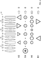
- FIG. 4 is a diagram illustrating a function of the aberration corrector 100.
- the aberration corrector 100 by generating the three-fold astigmatisms B1, B2, B3, and B4 illustrated in FIG. 3 described above in the four-stage multipoles (the first multipole 110, the second multipole 120, the third multipole 130, and the fourth multipole 140), a three-fold astigmatism, a spherical aberration, a six-fold astigmatism, and a sixth-order three-lobe aberration can be corrected as will be described below.
- aberrations a coma aberration, a star aberration, and the like
- a deflection coil not illustrated
- Three-fold astigmatisms are respectively generated in the first multipole 110 and the second multipole 120.
- the three-fold astigmatism generated in the first multipole 110 and the three-fold astigmatism generated in the second multipole 120 cancel each other out.
- Three-fold astigmatisms are respectively generated in the third multipole 130 and the fourth multipole 140.
- the three-fold astigmatism generated in the third multipole 130 and the three-fold astigmatism generated in the fourth multipole 140 cancel each other out. Therefore, in the aberration corrector 100, for example, the three-fold astigmatism can be made zero.
- the first multipole 110 generates a negative spherical aberration.
- the second multipole 120, the third multipole 130, and the fourth multipole 140 respectively generate negative spherical aberrations.
- a positive spherical aberration of the imaging system can be corrected using the negative spherical aberrations generated by the four-stage multipoles.
- a six-fold astigmatism is created by the three-fold symmetric field generated by the first multipole 110.
- a six-fold astigmatism is created by the three-fold symmetric field generated by the second multipole 120.
- a six-fold astigmatism is created by the three-fold symmetric field generated by the third multipole 130.
- a six-fold astigmatism is created by the three-fold symmetric field generated by the fourth multipole 140.
- a six-fold astigmatism is also created as a combination aberration of the three-fold symmetric fields generated by the first multipole 110, the second multipole 120, the third multipole 130, and the fourth multipole 140.
- spherical aberrations are respectively created in the first transfer lens system 150, the second transfer lens system 160, and the third transfer lens system 170.
- a six-fold astigmatism is created by a combination aberration of the spherical aberrations created in the transfer lens systems and the aberrations created by the three-fold symmetric fields generated by the multipoles 110, 120, 130, and 140.
- a six-fold astigmatism of the aberration corrector 100 as a whole is corrected by achieving a balance between the six-fold astigmatism generated by the three-fold symmetric fields respectively generated by the first multipole 110, the second multipole 120, the third multipole 130, and the fourth multipole 140 and the six-fold astigmatism generated by the combination aberration of the spherical aberrations created in the transfer lens systems 150, 160, and 170 and the aberrations created by the three-fold symmetric fields generated by the multipoles. Accordingly, for example, the six-fold astigmatism can be made zero in the aberration corrector 100 as a whole.
- a sixth-order three-lobe aberration generated in the first multipole 110 and the second multipole 120 and a sixth-order three-lobe aberration generated in the third multipole 130 and the fourth multipole 140 cancel each other out. Accordingly, in the aberration corrector 100, a sixth-order three-lobe aberration can be corrected and, for example, the sixth-order three-lobe aberration can be made zero in the aberration corrector 100 as a whole.
- the aberration corrector 100 has the following features.
- the aberration corrector 100 includes: the first multipole 110, the second multipole 120, the third multipole 130, and the fourth multipole 140 which generate three-fold symmetric fields; the first transfer lens system 150 arranged between the first multipole 110 and the second multipole 120 ; the second transfer lens system 160 arranged between the second multipole 120 and the third multipole 130; and the third transfer lens system 170 arranged between the third multipole 130 and the fourth multipole 140. Therefore, in the aberration corrector 100, as described above, a spherical aberration of an imaging system can be corrected and a sixth-order three-lobe aberration generated in the aberration corrector 100 can be corrected.
- the first multipole 110, the second multipole 120, the third multipole 130, and the fourth multipole 140 are arranged in an order of the first multipole 110, the second multipole 120, the third multipole 130, and the fourth multipole 140 from the side of the objective lens 30.
- an intensity of the three-fold astigmatism B1 created by the three-fold symmetric field generated by the first multipole 110 is equal to an intensity of the three-fold astigmatism B2 created by the three-fold symmetric field generated by the second multipole 120
- an orientation of the three-fold astigmatism B2 is an orientation obtained by rotating the three-fold astigmatism B1 by 60 degrees.
- an intensity of the three-fold astigmatism B3 created by the three-fold symmetric field generated by the third multipole 130 is equal to an intensity of the three-fold astigmatism B4 created by the three-fold symmetric field generated by the fourth multipole 140
- an orientation of the three-fold astigmatism B4 is an orientation obtained by rotating the three-fold astigmatism B3 by 60 degrees.
- the orientation of the three-fold astigmatism B2 and the orientation of the three-fold astigmatism B3 are the same. Furthermore, the intensity of the three-fold astigmatism B2 is lower than the intensity of the three-fold astigmatism B3.
- a spherical aberration of an imaging system can be corrected and, at the same time, a three-fold astigmatism, a six-fold astigmatism, and a sixth-order three-lobe aberration can be corrected.
- a sixth-order three-lobe aberration generated in the first multipole 110 and the second multipole 120 and a sixth-order three-lobe aberration generated in the third multipole 130 and the fourth multipole 140 cancel each other out. Therefore, in the aberration corrector 100, a sixth-order three-lobe aberration can be corrected.
- the first multipole 110, the second multipole 120, the third multipole 130, and the fourth multipole 140 generate negative spherical aberrations. Therefore, in the aberration corrector 100, a positive spherical aberration of an imaging system can be canceled out.
- a three-fold astigmatism generated in the first multipole 110 and a three-fold astigmatism generated in the second multipole 120 cancel each other out
- a three-fold astigmatism generated in the third multipole 130 and a three-fold astigmatism generated in the fourth multipole 140 cancel each other out. Therefore, in the aberration corrector 100, a three-fold astigmatism can be corrected.
- a six-fold astigmatism is corrected by: a six-fold astigmatism generated by the three-fold symmetric fields respectively generated by the first multipole 110, the second multipole 120, the third multipole 130, and the fourth multipole 140; and a six-fold astigmatism generated by a combination aberration of the spherical aberrations generated by the transfer lens systems 150, 160, and 170 and the aberrations created by the three-fold symmetric fields generated by the multipoles 110, 120, 130, and 140. Therefore, in the aberration corrector 100, a six-fold astigmatism can be corrected.
- the electron microscope 1 includes the aberration corrector 100, a resolution of an electron microscope image can be improved.
- the relationship among the three-fold astigmatisms B1, B2, B3, and B4 created by the three-fold symmetric fields is not limited to the example illustrated in FIG. 3 as long as a spherical aberration and a sixth-order three-lobe aberration can be corrected.
- FIG. 5 is a diagram illustrating a configuration of an electron microscope 2 according to the second embodiment.
- members having similar functions to the components of the electron microscope 1 according to the first embodiment will be denoted by same reference characters and a detailed description thereof will be omitted.
- the electron microscope 2 includes an aberration corrector according to an embodiment of the invention.
- a case where an aberration corrector 200 is included as the aberration corrector according to an embodiment of the invention will now be described.
- the aberration corrector 100 is built into the imaging system as illustrated in FIG. 1 .
- the aberration corrector 200 is built into an illumination system as illustrated in FIG. 5 .
- the electron microscope 2 is configured so as to include the electron gun 10, the condenser lens 20, the aberration corrector 200, the objective lens 30, the specimen stage 40, the intermediate projector lens 50, and the detector 60.
- the aberration corrector 200 is built into an illumination system of the electron microscope 2.
- the aberration corrector 200 corrects spherical aberration of the illumination system (the objective lens 30). Specifically, in the aberration corrector 200, a positive spherical aberration of the illumination system is canceled out by a negative spherical aberration generated by the aberration corrector 200.
- FIG. 6 is a diagram illustrating a configuration of the aberration corrector 200.
- the aberration corrector 200 is arranged in front of the objective lens 30.
- the transfer lens system 32 is arranged between the aberration corrector 200 (the first multipole 110) and the objective lens 30.
- the transfer lens system 32 is constituted by two transfer lenses (the first transfer lens 32a and the second transfer lens 32b).
- the aberration corrector 200 includes four-stage multipoles (the first multipole 110, the second multipole 120, the third multipole 130, and the fourth multipole 140) and three transfer lens systems (the first transfer lens system 150, the second transfer lens system 160, and the third transfer lens system 170).
- the first multipole 110, the second multipole 120, the third multipole 130, and the fourth multipole 140 are arranged along an optical axis A.
- the four-stage multipoles are arranged in an order of the first multipole 110, the second multipole 120, the third multipole 130, and the fourth multipole 140 from the side of the objective lens 30.
- An arrangement of the four-stage multipoles in the aberration corrector 200 illustrated in FIG. 6 and an arrangement of the four-stage multipoles in the aberration corrector 100 illustrated in FIG. 2 are symmetrical with respect to the objective lens 30.
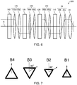
- FIG. 7 is a diagram illustrating a relationship among a three-fold astigmatism B1 created by a three-fold symmetric field generated by the first multipole 110, a three-fold astigmatism B2 created by a three-fold symmetric field generated by the second multipole 120, a three-fold astigmatism B3 created by a three-fold symmetric field generated by the third multipole 130, and a three-fold astigmatism B4 created by a three-fold symmetric field generated by the fourth multipole 140.
- the relationship among the three-fold astigmatism B1 created by the three-fold symmetric field generated by the first multipole 110, the three-fold astigmatism B2 created by the three-fold symmetric field generated by the second multipole 120, the three-fold astigmatism B3 created by the three-fold symmetric field generated by the third multipole 130, and the three-fold astigmatism B4 created by the three-fold symmetric field generated by the fourth multipole 140 in the aberration corrector 200 is the same as the relationship among the three-fold astigmatism B1 created by the three-fold symmetric field generated by the first multipole 110, the three-fold astigmatism B2 created by the three-fold symmetric field generated by the second multipole 120, the three-fold astigmatism B3 created by the three-fold symmetric field generated by the third multipole 130, and the three-fold astigmatism B4 created by the three-fold symmetric field generated by the fourth multipole 140 in the aberration corrector 100 described earlier.
- the intensity of the three-fold astigmatism B1 is equal to the intensity of the three-fold astigmatism B2.
- the orientation of the three-fold astigmatism B2 is an orientation obtained by rotating the three-fold astigmatism B1 by 60 degrees.
- the intensity of the three-fold astigmatism B3 is equal to the intensity of the three-fold astigmatism B4.
- the orientation of the three-fold astigmatism B4 is an orientation obtained by rotating the three-fold astigmatism B3 by 60 degrees.
- the orientation of the three-fold astigmatism B2 and the orientation of the three-fold astigmatism B3 are the same.
- the intensity of the three-fold astigmatism B2 is lower than the intensity of the three-fold astigmatism B3.
- FIG. 8 is a diagram illustrating a function of the aberration corrector 200.
- the aberration corrector 200 by generating the three-fold astigmatisms B1, B2, B3, and B4 illustrated in FIG. 7 described above in the four-stage multipoles (the first multipole 110, the second multipole 120, the third multipole 130, and the fourth multipole 140), a three-fold astigmatism, a spherical aberration, a six-fold astigmatism, and a sixth-order three-lobe aberration can be corrected as will be described below.
- Three-fold astigmatisms are respectively generated in the first multipole 110 and the second multipole 120.
- the three-fold astigmatism generated in the first multipole 110 and the three-fold astigmatism generated in the second multipole 120 cancel each other out.
- Three-fold astigmatisms are respectively generated in the third multipole 130 and the fourth multipole 140.
- the three-fold astigmatism generated in the third multipole 130 and the three-fold astigmatism generated in the fourth multipole 140 cancel each other out. Therefore, in the aberration corrector 200, for example, the three-fold astigmatism can be made zero.
- the first multipole 110 generates a negative spherical aberration.
- the second multipole 120, the third multipole 130, and the fourth multipole 140 respectively generate negative spherical aberrations.
- a positive spherical aberration of the illumination system can be corrected using the negative spherical aberrations generated by the four-stage multipoles.
- a six-fold astigmatism of the aberration corrector 200 as a whole is corrected by achieving a balance between the six-fold astigmatism generated by the three-fold symmetric fields respectively generated by the first multipole 110, the second multipole 120, the third multipole 130, and the fourth multipole 140 and the six-fold astigmatism generated by the combination aberration of the spherical aberrations created in the transfer lens systems and the aberrations created by the three-fold symmetric fields generated by the multipoles in a similar manner to the aberration corrector 100. Accordingly, for example, the six-fold astigmatism can be made zero in the aberration corrector 200 as a whole.
- a sixth-order three-lobe aberration generated in the first multipole 110 and the second multipole 120 and a sixth-order three-lobe aberration generated in the third multipole 130 and the fourth multipole 140 cancel each other out. Accordingly, in the aberration corrector 200, a sixth-order three-lobe aberration can be corrected and, for example, the sixth-order three-lobe aberration can be made zero in the aberration corrector 200 as a whole.
- the aberration corrector 200 has the following features.
- the aberration corrector 200 can yield similar advantageous effects to the aberration corrector 100. Furthermore, in the aberration corrector 200, aberrations of an illumination system can be corrected.
- the invention includes configurations that are substantially the same (for example in function and method) as the configurations described in the embodiments.
- the invention also includes configurations in which non-essential elements described in the embodiments are replaced by other elements.
- the invention further includes configurations obtained by adding known art to the configurations described in the embodiments.
Landscapes
- Chemical & Material Sciences (AREA)
- Analytical Chemistry (AREA)
- Lenses (AREA)
- Electron Beam Exposure (AREA)
Abstract
Description
- The present invention relates to an aberration corrector and a charged particle beam device.
- In electron microscopes such as a transmission electron microscope (TEM) and a scanning electron microscope (SEM), aberration correction is an important technique in terms of acquiring a high resolution image.
- For example, a two-stage three-fold-field type Cs corrector in which hexapoles are arranged in two stages is disclosed in H. Rose (Optik, vol. 85, (1990) pp. 19-24), H. Haider et al. (Nature, vol. 392 (1998) pp. 768-769), H. Muller, et al. (Microsc. Microanal. 12, (2006) 442-455). In the Cs corrector disclosed in H. Rose (Optik, vol. 85, (1990) pp. 19-24), H. Haider et al. (Nature, vol. 392 (1998) pp. 768-769), H. Muller, et al. (Microsc. Microanal. 12, (2006) 442-455), a positive spherical aberration of an objective lens is corrected by a negative spherical aberration created by the hexapoles. In a two-stage three-fold-field type Cs corrector, although a six-fold astigmatism that is a fifth-order aberration in terms of geometrical aberration remains as a largest aberration, the six-fold astigmatism can be corrected by adjusting a thickness of multipoles and the like.
- In addition, a three-stage three-fold-field type Cs corrector in which three-fold symmetric fields are arranged in three stages is disclosed in H. Sawada et al. (Journal of Electron Microscopy, vol. 58 (2009) pp. 341-347) and H. Sawada et al. (Ultramicroscopy 110 (2010) 958-961). In the three-stage three-fold-field type Cs corrector, a six-fold astigmatism that is difficult to correct with the two-stage three-fold-field type Cs corrector described above is corrected by arranging three-fold fields in three stages.
- As described above, in a two-stage three-fold-field type Cs corrector, a six-fold astigmatism can be corrected by adjusting a thickness of multipoles and the like. However, even if the six-fold astigmatism is corrected, a sixth-order three-lobe aberration that is a sixth-order aberration in terms of geometrical aberration (a seventh-order aberration in terms of wave aberration) cannot be corrected and remains as an aberration that restricts an aberration-corrected range.
- In addition, in a three-stage three-fold-field type Cs corrector, a six-fold astigmatism can be corrected as described above. However, in the three-stage three-fold-field type Cs corrector, a sixth-order three-lobe aberration remains as a largest aberration after correcting a six-fold astigmatism in a similar manner to a two-stage three-fold-field type Cs corrector.
- The invention can provide an aberration corrector and a charged particle beam device capable of correcting a sixth-order three-lobe aberration.
- According to a first aspect of the invention, there is provided an aberration corrector including:
- a first multipole, a second multipole, a third multipole, and a fourth multipole arranged along an optical axis;
- a first transfer lens system arranged between the first multipole and the second multipole;
- a second transfer lens system arranged between the second multipole and the third multipole; and
- a third transfer lens system arranged between the third multipole and the fourth multipole,
- each of the first multipole, the second multipole, the third multipole, and the fourth multipole generating a three-fold symmetric field.
- According to a first aspect of the invention, there is provided a charged particle beam device including the aberration corrector described above.
-
-
FIG. 1 is a diagram illustrating a configuration of an electron microscope according to a first embodiment. -
FIG. 2 is a diagram illustrating a configuration of an aberration corrector. -
FIG. 3 is a diagram illustrating a relationship among a three-fold astigmatism created by a three-fold symmetric field generated by a first multipole, a three-fold astigmatism created by a three-fold symmetric field generated by a second multipole, a three-fold astigmatism created by a three-fold symmetric field generated by a third multipole, and a three-fold astigmatism created by a three-fold symmetric field generated by a fourth multipole. -
FIG. 4 is a diagram illustrating a function of an aberration corrector. -
FIG. 5 is a diagram illustrating a configuration of an electron microscope according to a second embodiment. -
FIG. 6 is a diagram illustrating a configuration of an aberration corrector. -
FIG. 7 is a diagram illustrating a relationship among a three-fold astigmatism created by a three-fold symmetric field generated by a first multipole, a three-fold astigmatism created by a three-fold symmetric field generated by a second multipole, a three-fold astigmatism created by a three-fold symmetric field generated by a third multipole, and a three-fold astigmatism created by a three-fold symmetric field generated by a fourth multipole. -
FIG. 8 is a diagram illustrating a function of an aberration corrector. - According to an embodiment of the invention, there is provided an aberration corrector including:
- a first multipole, a second multipole, a third multipole, and a fourth multipole arranged along an optical axis;
- a first transfer lens system arranged between the first multipole and the second multipole;
- a second transfer lens system arranged between the second multipole and the third multipole; and
- a third transfer lens system arranged between the third multipole and the fourth multipole,
- each of the first multipole, the second multipole, the third multipole, and the fourth multipole generating a three-fold symmetric field.
- In such an aberration corrector, since the first multipole, the second multipole, the third multipole, and the fourth multipole respectively generate a three-fold symmetric field, a spherical aberration and a sixth-order three-lobe aberration can be corrected.
- According to an embodiment of the invention, there is provided a charged particle beam device including the aberration corrector described above.
- In such a charged particle beam device, a sixth-order three-lobe aberration can be corrected and resolution can be improved.
- Embodiments of the invention are described in detail below with reference to the drawings. Note that the following embodiments do not unduly limit the scope of the invention as stated in the claims. In addition, all of the elements described in connection with the following embodiments should not necessarily be taken as essential requirements of the invention.
- Furthermore, while the charged particle beam device according to an embodiment of the invention will be described below by using an electron microscope that performs an observation, an analysis, and the like of a specimen by irradiating an electron beam as an example, the charged particle beam device according to the invention may be an apparatus that performs an observation, an analysis, and the like of a specimen by irradiating a charged particle beam (such as an ion beam) other than an electron beam.
- First, an electron microscope according to a first embodiment will be described with reference to the drawings.
FIG. 1 is a diagram illustrating a configuration of an electron microscope 1 according to the first embodiment. - The electron microscope 1 includes an aberration corrector according to an embodiment of the invention. A case where an
aberration corrector 100 is included as the aberration corrector according to an embodiment of the invention will now be described. - As illustrated in
FIG. 1 , the electron microscope 1 is configured so as to include anelectron gun 10, acondenser lens 20, anobjective lens 30, a specimen stage 40, theaberration corrector 100, anintermediate projector lens 50, and adetector 60. In the electron microscope 1, theaberration corrector 100 is used in order to correct an aberration of an imaging system. - The
electron gun 10 generates an electron beam. Thecondenser lens 20 focuses the electron beam emitted from theelectron gun 10. Thecondenser lens 20 constitutes an illumination system for illuminating a specimen with the electron beam. Theobjective lens 30 is a lens in a first stage for forming an image with the electron beam having been transmitted through the specimen. The specimen stage 40 holds the specimen. Theintermediate projector lens 50 cooperates with theobjective lens 30 to constitute an imaging system for forming an image with the electron beam having been transmitted through the specimen. Theintermediate projector lens 50 forms an image on thedetector 60 inside an observation chamber. Accordingly, thedetector 60 can photograph a transmission electron microscope image. - The
aberration corrector 100 is built into the imaging system of the electron microscope 1. Theaberration corrector 100 corrects a spherical aberration of the imaging system (the objective lens 30). Specifically, in theaberration corrector 100, a positive spherical aberration of the imaging system is canceled out by a negative spherical aberration generated by theaberration corrector 100. -
FIG. 2 is a diagram illustrating a configuration of theaberration corrector 100. - As illustrated in
FIG. 2 , theaberration corrector 100 is arranged behind theobjective lens 30. Atransfer lens system 32 is arranged between theobjective lens 30 and the aberration corrector 100 (a first multipole 110). Thetransfer lens system 32 is constituted by a pair of transfer lenses (afirst transfer lens 32a and asecond transfer lens 32b). - The
aberration corrector 100 includes four-stage multipoles (thefirst multipole 110, asecond multipole 120, athird multipole 130, and a fourth multipole 140) and three transfer lens systems (a firsttransfer lens system 150, a secondtransfer lens system 160, and a third transfer lens system 170). - The
first multipole 110, thesecond multipole 120, thethird multipole 130, and thefourth multipole 140 are arranged along an optical axis A. The four-stage multipoles are arranged in an order of thefirst multipole 110, thesecond multipole 120, thethird multipole 130, and thefourth multipole 140 from the side of theobjective lens 30. - The
first multipole 110 generates a three-fold symmetric field. A three-fold symmetric field refers to a field of which an intensity has three-fold symmetry. The three-fold symmetric field generated by thefirst multipole 110 is an electric field having three-fold symmetry, a magnetic field having three-fold symmetry, or a crossed field of a magnetic field and an electric field having three-fold symmetry. Thefirst multipole 110 is, for example, a hexapole or a dodecapole. Note that thefirst multipole 110 need only be capable of generating a three-fold symmetric field and is not limited to a hexapole or a dodecapole. - The
first multipole 110 is has a thickness along the optical axis A. In a multipole having a thickness, an aberration that differs from an aberration generated in a thin multipole appears as a combination aberration. In a multipole that generates a three-fold symmetric field, a negative spherical aberration is created as a combination aberration. Theaberration corrector 100 uses this negative spherical aberration to correct a positive spherical aberration of an imaging system. In addition, in a multipole having a thickness along the optical axis A and which generates a three-fold symmetric field, a fourth-order three-lobe aberration, a six-fold astigmatism, a fifth-order spherical aberration, and a sixth-order three-lobe aberration are generated as combination aberrations in addition to the negative spherical aberration. - Configurations of the
second multipole 120, thethird multipole 130, and thefourth multipole 140 are the same as the configuration of thefirst multipole 110. In other words, thesecond multipole 120, thethird multipole 130, and thefourth multipole 140 respectively generate three-fold symmetric fields. Thesecond multipole 120, thethird multipole 130, and thefourth multipole 140 each have a thickness along the optical axis A. - The first
transfer lens system 150 is arranged between thefirst multipole 110 and thesecond multipole 120. The firsttransfer lens system 150 is constituted by a pair of transfer lenses (afirst transfer lens 150a and asecond transfer lens 150b). The firsttransfer lens system 150 forms, in thesecond multipole 120, an image conjugate to an image formed by thefirst multipole 110. - The second
transfer lens system 160 is arranged between thesecond multipole 120 and thethird multipole 130. The secondtransfer lens system 160 is constituted by a pair of transfer lenses (afirst transfer lens 160a and asecond transfer lens 160b). The secondtransfer lens system 160 forms, in thethird multipole 130, an image conjugate to an image formed by thesecond multipole 120. - The third
transfer lens system 170 is arranged between thethird multipole 130 and thefourth multipole 140. The thirdtransfer lens system 170 is constituted by a pair of transfer lenses (afirst transfer lens 170a and asecond transfer lens 170b). The thirdtransfer lens system 170 forms, in thefourth multipole 140, an image conjugate to an image formed by thethird multipole 130. - It should be noted that the transfer lenses constituting the first
transfer lens system 150, the secondtransfer lens system 160, and the thirdtransfer lens system 170 may be a rotationally symmetric (axially symmetric) lens or may be a multipole lens as long as a conjugate image can be formed. -
FIG. 3 is a diagram illustrating a relationship among a three-fold astigmatism B1 created by a three-fold symmetric field generated by thefirst multipole 110, a three-fold astigmatism B2 created by a three-fold symmetric field generated by thesecond multipole 120, a three-fold astigmatism B3 created by a three-fold symmetric field generated by thethird multipole 130, and a three-fold astigmatism B4 created by a three-fold symmetric field generated by thefourth multipole 140. - An intensity of the three-fold astigmatism B 1 created by the three-fold symmetric field generated by the
first multipole 110 is equal to an intensity of the three-fold astigmatism B2 created by the three-fold symmetric field generated by thesecond multipole 120. In addition, an orientation of the three-fold astigmatism B2 created by the three-fold symmetric field generated by thesecond multipole 120 is an orientation obtained by rotating the three-fold astigmatism B1 created by the three-fold symmetric field generated by thefirst multipole 110 by 60 degrees. In other words, the three-fold astigmatism B2 created by the three-fold symmetric field generated by thesecond multipole 120 is a field obtained by rotating, around the optical axis A by 60 degrees, the three-fold astigmatism B1 created by the three-fold symmetric field generated by thefirst multipole 110. An orientation of a three-fold symmetric field generated by a multipole is the same as an orientation of a three-fold astigmatism created by the three-fold symmetric field generated by the multipole. In other words, an orientation of the three-fold symmetric field generated by thesecond multipole 120 is an orientation obtained by rotating the three-fold symmetric field generated by thefirst multipole 110 by 60 degrees. - An intensity of the three-fold astigmatism B3 created by the three-fold symmetric field generated by the
third multipole 130 is equal to an intensity of the three-fold astigmatism B4 created by the three-fold symmetric field generated by thefourth multipole 140. In addition, an orientation of the three-fold astigmatism B4 created by the three-fold symmetric field generated by thefourth multipole 140 is an orientation obtained by rotating the three-fold astigmatism B3 created by the three-fold symmetric field generated by thethird multipole 130 by 60 degrees. In other words, the three-fold astigmatism B4 created by the three-fold symmetric field generated by thefourth multipole 140 is a field obtained by rotating, around the optical axis A by 60 degrees, the three-fold astigmatism B3 created by the three-fold symmetric field generated by thethird multipole 130. In other words, an orientation of the three-fold symmetric field generated by thethird multipole 130 is an orientation obtained by rotating the three-fold symmetric field generated by thefourth multipole 140 by 60 degrees. - An orientation of the three-fold astigmatism B2 created by the three-fold symmetric field generated by the
second multipole 120 is the same as an orientation of the three-fold astigmatism B3 created by the three-fold symmetric field generated by thethird multipole 130. In other words, an orientation of the three-fold symmetric field generated by thesecond multipole 120 is the same as an orientation of the three-fold symmetric field generated by thethird multipole 130. In addition, an intensity of the three-fold astigmatism B2 created by the three-fold symmetric field generated by thesecond multipole 120 is lower than an intensity of the three-fold astigmatism B3 created by the three-fold symmetric field generated by thethird multipole 130. For example, a ratio B2: B3 of the intensity of the three-fold astigmatism B2 created by the three-fold symmetric field generated by thesecond multipole 120 to the intensity of the three-fold astigmatism B3 created by the three-fold symmetric field generated by thethird multipole 130 is B2: B3 = 1: x, where x is 0.4 < x < 0.8. The ratio B2: B3 is set in accordance with a focal length of theobjective lens 30, a spherical aberration coefficient of theobjective lens 30, a transfer magnification, a focal length of the transfer lenses, a spherical aberration coefficient of the transfer lenses, a thickness of the multipoles, and the like. -
FIG. 4 is a diagram illustrating a function of theaberration corrector 100. In theaberration corrector 100, by generating the three-fold astigmatisms B1, B2, B3, and B4 illustrated inFIG. 3 described above in the four-stage multipoles (thefirst multipole 110, thesecond multipole 120, thethird multipole 130, and the fourth multipole 140), a three-fold astigmatism, a spherical aberration, a six-fold astigmatism, and a sixth-order three-lobe aberration can be corrected as will be described below. It should be noted that aberrations (a coma aberration, a star aberration, and the like) other than the aberrations illustrated inFIG. 4 can be corrected using a deflection coil (not illustrated) mounted to theaberration corrector 100. - Three-fold astigmatisms are respectively generated in the
first multipole 110 and thesecond multipole 120. The three-fold astigmatism generated in thefirst multipole 110 and the three-fold astigmatism generated in thesecond multipole 120 cancel each other out. - Three-fold astigmatisms are respectively generated in the
third multipole 130 and thefourth multipole 140. The three-fold astigmatism generated in thethird multipole 130 and the three-fold astigmatism generated in thefourth multipole 140 cancel each other out. Therefore, in theaberration corrector 100, for example, the three-fold astigmatism can be made zero. - The
first multipole 110 generates a negative spherical aberration. In a similar manner, thesecond multipole 120, thethird multipole 130, and thefourth multipole 140 respectively generate negative spherical aberrations. A positive spherical aberration of the imaging system can be corrected using the negative spherical aberrations generated by the four-stage multipoles. - A six-fold astigmatism is created by the three-fold symmetric field generated by the
first multipole 110. In a similar manner, a six-fold astigmatism is created by the three-fold symmetric field generated by thesecond multipole 120. In a similar manner, a six-fold astigmatism is created by the three-fold symmetric field generated by thethird multipole 130. In a similar manner, a six-fold astigmatism is created by the three-fold symmetric field generated by thefourth multipole 140. In addition, a six-fold astigmatism is also created as a combination aberration of the three-fold symmetric fields generated by thefirst multipole 110, thesecond multipole 120, thethird multipole 130, and thefourth multipole 140. - Furthermore, spherical aberrations are respectively created in the first
transfer lens system 150, the secondtransfer lens system 160, and the thirdtransfer lens system 170. A six-fold astigmatism is created by a combination aberration of the spherical aberrations created in the transfer lens systems and the aberrations created by the three-fold symmetric fields generated by themultipoles - In the
aberration corrector 100, a six-fold astigmatism of theaberration corrector 100 as a whole is corrected by achieving a balance between the six-fold astigmatism generated by the three-fold symmetric fields respectively generated by thefirst multipole 110, thesecond multipole 120, thethird multipole 130, and thefourth multipole 140 and the six-fold astigmatism generated by the combination aberration of the spherical aberrations created in thetransfer lens systems aberration corrector 100 as a whole. - In the
aberration corrector 100, a sixth-order three-lobe aberration generated in thefirst multipole 110 and thesecond multipole 120 and a sixth-order three-lobe aberration generated in thethird multipole 130 and thefourth multipole 140 cancel each other out. Accordingly, in theaberration corrector 100, a sixth-order three-lobe aberration can be corrected and, for example, the sixth-order three-lobe aberration can be made zero in theaberration corrector 100 as a whole. - For example, the
aberration corrector 100 has the following features. - The
aberration corrector 100 includes: thefirst multipole 110, thesecond multipole 120, thethird multipole 130, and thefourth multipole 140 which generate three-fold symmetric fields; the firsttransfer lens system 150 arranged between thefirst multipole 110 and thesecond multipole 120 ; the secondtransfer lens system 160 arranged between thesecond multipole 120 and thethird multipole 130; and the thirdtransfer lens system 170 arranged between thethird multipole 130 and thefourth multipole 140. Therefore, in theaberration corrector 100, as described above, a spherical aberration of an imaging system can be corrected and a sixth-order three-lobe aberration generated in theaberration corrector 100 can be corrected. - In the
aberration corrector 100, thefirst multipole 110, thesecond multipole 120, thethird multipole 130, and thefourth multipole 140 are arranged in an order of thefirst multipole 110, thesecond multipole 120, thethird multipole 130, and thefourth multipole 140 from the side of theobjective lens 30. In addition, an intensity of the three-fold astigmatism B1 created by the three-fold symmetric field generated by thefirst multipole 110 is equal to an intensity of the three-fold astigmatism B2 created by the three-fold symmetric field generated by thesecond multipole 120, and an orientation of the three-fold astigmatism B2 is an orientation obtained by rotating the three-fold astigmatism B1 by 60 degrees. Furthermore, an intensity of the three-fold astigmatism B3 created by the three-fold symmetric field generated by thethird multipole 130 is equal to an intensity of the three-fold astigmatism B4 created by the three-fold symmetric field generated by thefourth multipole 140, and an orientation of the three-fold astigmatism B4 is an orientation obtained by rotating the three-fold astigmatism B3 by 60 degrees. - In addition, the orientation of the three-fold astigmatism B2 and the orientation of the three-fold astigmatism B3 are the same. Furthermore, the intensity of the three-fold astigmatism B2 is lower than the intensity of the three-fold astigmatism B3.
- Therefore, in the
aberration corrector 100, a spherical aberration of an imaging system can be corrected and, at the same time, a three-fold astigmatism, a six-fold astigmatism, and a sixth-order three-lobe aberration can be corrected. - In the
aberration corrector 100, a sixth-order three-lobe aberration generated in thefirst multipole 110 and thesecond multipole 120 and a sixth-order three-lobe aberration generated in thethird multipole 130 and thefourth multipole 140 cancel each other out. Therefore, in theaberration corrector 100, a sixth-order three-lobe aberration can be corrected. - In the
aberration corrector 100, thefirst multipole 110, thesecond multipole 120, thethird multipole 130, and thefourth multipole 140 generate negative spherical aberrations. Therefore, in theaberration corrector 100, a positive spherical aberration of an imaging system can be canceled out. - In the
aberration corrector 100, a three-fold astigmatism generated in thefirst multipole 110 and a three-fold astigmatism generated in thesecond multipole 120 cancel each other out, and a three-fold astigmatism generated in thethird multipole 130 and a three-fold astigmatism generated in thefourth multipole 140 cancel each other out. Therefore, in theaberration corrector 100, a three-fold astigmatism can be corrected. - In the
aberration corrector 100, a six-fold astigmatism is corrected by: a six-fold astigmatism generated by the three-fold symmetric fields respectively generated by thefirst multipole 110, thesecond multipole 120, thethird multipole 130, and thefourth multipole 140; and a six-fold astigmatism generated by a combination aberration of the spherical aberrations generated by thetransfer lens systems multipoles aberration corrector 100, a six-fold astigmatism can be corrected. - Since the electron microscope 1 includes the
aberration corrector 100, a resolution of an electron microscope image can be improved. - While a case where a spherical aberration and a sixth-order three-lobe aberration are corrected by causing the three-fold symmetric fields illustrated in
FIG. 3 described above to be generated in the four-stage multipoles (thefirst multipole 110, thesecond multipole 120, thethird multipole 130, and the fourth multipole 140) has been described above, the relationship among the three-fold astigmatisms B1, B2, B3, and B4 created by the three-fold symmetric fields is not limited to the example illustrated inFIG. 3 as long as a spherical aberration and a sixth-order three-lobe aberration can be corrected. - Next, an electron microscope according to a second embodiment will be described with reference to the drawings.
FIG. 5 is a diagram illustrating a configuration of anelectron microscope 2 according to the second embodiment. Hereinafter, in theelectron microscope 2 according to the second embodiment, members having similar functions to the components of the electron microscope 1 according to the first embodiment will be denoted by same reference characters and a detailed description thereof will be omitted. - The
electron microscope 2 includes an aberration corrector according to an embodiment of the invention. A case where anaberration corrector 200 is included as the aberration corrector according to an embodiment of the invention will now be described. - In the electron microscope 1 described above, the
aberration corrector 100 is built into the imaging system as illustrated inFIG. 1 . - In contrast, in the
electron microscope 2, theaberration corrector 200 is built into an illumination system as illustrated inFIG. 5 . - The
electron microscope 2 is configured so as to include theelectron gun 10, thecondenser lens 20, theaberration corrector 200, theobjective lens 30, the specimen stage 40, theintermediate projector lens 50, and thedetector 60. - The
aberration corrector 200 is built into an illumination system of theelectron microscope 2. Theaberration corrector 200 corrects spherical aberration of the illumination system (the objective lens 30). Specifically, in theaberration corrector 200, a positive spherical aberration of the illumination system is canceled out by a negative spherical aberration generated by theaberration corrector 200. -
FIG. 6 is a diagram illustrating a configuration of theaberration corrector 200. - As illustrated in
FIG. 6 , theaberration corrector 200 is arranged in front of theobjective lens 30. Thetransfer lens system 32 is arranged between the aberration corrector 200 (the first multipole 110) and theobjective lens 30. Thetransfer lens system 32 is constituted by two transfer lenses (thefirst transfer lens 32a and thesecond transfer lens 32b). - The
aberration corrector 200 includes four-stage multipoles (thefirst multipole 110, thesecond multipole 120, thethird multipole 130, and the fourth multipole 140) and three transfer lens systems (the firsttransfer lens system 150, the secondtransfer lens system 160, and the third transfer lens system 170). - The
first multipole 110, thesecond multipole 120, thethird multipole 130, and thefourth multipole 140 are arranged along an optical axis A. The four-stage multipoles are arranged in an order of thefirst multipole 110, thesecond multipole 120, thethird multipole 130, and thefourth multipole 140 from the side of theobjective lens 30. - An arrangement of the four-stage multipoles in the
aberration corrector 200 illustrated inFIG. 6 and an arrangement of the four-stage multipoles in theaberration corrector 100 illustrated inFIG. 2 are symmetrical with respect to theobjective lens 30. -
FIG. 7 is a diagram illustrating a relationship among a three-fold astigmatism B1 created by a three-fold symmetric field generated by thefirst multipole 110, a three-fold astigmatism B2 created by a three-fold symmetric field generated by thesecond multipole 120, a three-fold astigmatism B3 created by a three-fold symmetric field generated by thethird multipole 130, and a three-fold astigmatism B4 created by a three-fold symmetric field generated by thefourth multipole 140. - The relationship among the three-fold astigmatism B1 created by the three-fold symmetric field generated by the
first multipole 110, the three-fold astigmatism B2 created by the three-fold symmetric field generated by thesecond multipole 120, the three-fold astigmatism B3 created by the three-fold symmetric field generated by thethird multipole 130, and the three-fold astigmatism B4 created by the three-fold symmetric field generated by thefourth multipole 140 in theaberration corrector 200 is the same as the relationship among the three-fold astigmatism B1 created by the three-fold symmetric field generated by thefirst multipole 110, the three-fold astigmatism B2 created by the three-fold symmetric field generated by thesecond multipole 120, the three-fold astigmatism B3 created by the three-fold symmetric field generated by thethird multipole 130, and the three-fold astigmatism B4 created by the three-fold symmetric field generated by thefourth multipole 140 in theaberration corrector 100 described earlier. - Specifically, the intensity of the three-fold astigmatism B1 is equal to the intensity of the three-fold astigmatism B2. In addition, the orientation of the three-fold astigmatism B2 is an orientation obtained by rotating the three-fold astigmatism B1 by 60 degrees. Furthermore, the intensity of the three-fold astigmatism B3 is equal to the intensity of the three-fold astigmatism B4. In addition, the orientation of the three-fold astigmatism B4 is an orientation obtained by rotating the three-fold astigmatism B3 by 60 degrees. Furthermore, the orientation of the three-fold astigmatism B2 and the orientation of the three-fold astigmatism B3 are the same. In addition, the intensity of the three-fold astigmatism B2 is lower than the intensity of the three-fold astigmatism B3.
-
FIG. 8 is a diagram illustrating a function of theaberration corrector 200. In theaberration corrector 200, by generating the three-fold astigmatisms B1, B2, B3, and B4 illustrated inFIG. 7 described above in the four-stage multipoles (thefirst multipole 110, thesecond multipole 120, thethird multipole 130, and the fourth multipole 140), a three-fold astigmatism, a spherical aberration, a six-fold astigmatism, and a sixth-order three-lobe aberration can be corrected as will be described below. - Three-fold astigmatisms are respectively generated in the
first multipole 110 and thesecond multipole 120. The three-fold astigmatism generated in thefirst multipole 110 and the three-fold astigmatism generated in thesecond multipole 120 cancel each other out. - Three-fold astigmatisms are respectively generated in the
third multipole 130 and thefourth multipole 140. The three-fold astigmatism generated in thethird multipole 130 and the three-fold astigmatism generated in thefourth multipole 140 cancel each other out. Therefore, in theaberration corrector 200, for example, the three-fold astigmatism can be made zero. - The
first multipole 110 generates a negative spherical aberration. In a similar manner, thesecond multipole 120, thethird multipole 130, and thefourth multipole 140 respectively generate negative spherical aberrations. A positive spherical aberration of the illumination system can be corrected using the negative spherical aberrations generated by the four-stage multipoles. - In the
aberration corrector 200, a six-fold astigmatism of theaberration corrector 200 as a whole is corrected by achieving a balance between the six-fold astigmatism generated by the three-fold symmetric fields respectively generated by thefirst multipole 110, thesecond multipole 120, thethird multipole 130, and thefourth multipole 140 and the six-fold astigmatism generated by the combination aberration of the spherical aberrations created in the transfer lens systems and the aberrations created by the three-fold symmetric fields generated by the multipoles in a similar manner to theaberration corrector 100. Accordingly, for example, the six-fold astigmatism can be made zero in theaberration corrector 200 as a whole. - In the
aberration corrector 200, a sixth-order three-lobe aberration generated in thefirst multipole 110 and thesecond multipole 120 and a sixth-order three-lobe aberration generated in thethird multipole 130 and thefourth multipole 140 cancel each other out. Accordingly, in theaberration corrector 200, a sixth-order three-lobe aberration can be corrected and, for example, the sixth-order three-lobe aberration can be made zero in theaberration corrector 200 as a whole. - For example, the
aberration corrector 200 has the following features. - The
aberration corrector 200 can yield similar advantageous effects to theaberration corrector 100. Furthermore, in theaberration corrector 200, aberrations of an illumination system can be corrected. - The invention includes configurations that are substantially the same (for example in function and method) as the configurations described in the embodiments. The invention also includes configurations in which non-essential elements described in the embodiments are replaced by other elements. The invention further includes configurations obtained by adding known art to the configurations described in the embodiments.
- Some embodiments of the invention have been described in detail above, but a person skilled in the art will readily appreciate that various modifications can be made from the embodiments without materially departing from the novel teachings and effects of the invention as defined by the claims. Accordingly, all such modifications are assumed to be included in the scope of the invention.
Claims (13)
- An aberration corrector comprising:a first multipole, a second multipole, a third multipole and a fourth multipole arranged along an optical axis;a first transfer lens system arranged between the first multipole and the second multipole;a second transfer lens system arranged between the second multipole and the third multipole; anda third transfer lens system arranged between the third multipole and the fourth multipole,each of the first multipole, the second multipole, the third multipole, and the fourth multipole generating a three-fold symmetric field.
- The aberration corrector according to claim 1, wherein
the first multipole, the second multipole, the third multipole, and the fourth multipole are arranged in an order of the first multipole, the second multipole, the third multipole, and the fourth multipole,
an intensity of a three-fold astigmatism created by the three-fold symmetric field generated by the first multipole is equal to an intensity of a three-fold astigmatism created by the three-fold symmetric field generated by the second multipole,
an orientation of the three-fold symmetric field generated by the second multipole is an orientation obtained by rotating the three-fold symmetric field generated by the first multipole by 60 degrees,
an intensity of a three-fold astigmatism created by the three-fold symmetric field generated by the third multipole is equal to an intensity of a three-fold astigmatism created by the three-fold symmetric field generated by the fourth multipole, and
an orientation of the three-fold symmetric field generated by the fourth multipole is an orientation obtained by rotating the three-fold symmetric field generated by the third multipole by 60 degrees. - The aberration corrector according to claim 1 or 2, wherein
an orientation of the three-fold symmetric field generated by the second multipole and an orientation of the three-fold symmetric field generated by the third multipole are the same. - The aberration corrector according to any one of claims 1 to 3, wherein
an intensity of a three-fold astigmatism created by the three-fold symmetric field generated by the second multipole is lower than an intensity of a three-fold astigmatism created by the three-fold symmetric field generated by the third multipole. - The aberration corrector according to any one of claims 1 to 4, wherein
a sixth-order three-lobe aberration generated in the first multipole and the second multipole and a sixth-order three-lobe aberration generated in the third multipole and the fourth multipole cancel each other out. - The aberration corrector according to any one of claims 1 to 5, wherein
the first multipole, the second multipole, the third multipole, and the fourth multipole generate a negative spherical aberration. - The aberration corrector according to any one of claims 1 to 6, wherein
a three-fold astigmatism generated in the first multipole and a three-fold astigmatism generated in the second multipole cancel each other out, and
a three-fold astigmatism generated in the third multipole and a three-fold astigmatism generated in the fourth multipole cancel each other out. - The aberration corrector according to any one of claims 1 to 7, wherein
a six-fold astigmatism is corrected by:a six-fold astigmatism generated by the three-fold symmetric fields respectively generated by the first multipole, the second multipole, the third multipole, and the fourth multipole; anda six-fold astigmatism generated by a combination aberration of spherical aberrations respectively created in the first transfer lens system, the second transfer lens system, and the third transfer lens system and aberrations created by the three-fold symmetric fields respectively generated by the first multipole, the second multipole, the third multipole, and the fourth multipole. - The aberration corrector according to any one of claims 1 to 8, wherein
the first multipole, the second multipole, the third multipole, and the fourth multipole are arranged in an order of the first multipole, the second multipole, the third multipole, and the fourth multipole from an objective lens side. - The aberration corrector according to any one of claims 1 to 9, wherein
the three-fold symmetric field generated by each of the first multipole, the second multipole, the third multipole, and the fourth multipole is a magnetic field having three-fold symmetry, an electric field having three-fold symmetry, or a crossed field of a magnetic field and an electric field having three-fold symmetry. - The aberration corrector according to any one of claims 1 to 10, wherein
the first multipole, the second multipole, the third multipole, and the fourth multipole are hexapoles or dodecapoles. - The aberration corrector according to any one of claims 1 to 11, wherein
each of the first multipole, the second multipole, the third multipole, and the fourth multipole has a thickness along an optical axis. - A charged particle beam device comprising the aberration corrector according to any one of claims 1 to 12.
Applications Claiming Priority (1)
| Application Number | Priority Date | Filing Date | Title |
|---|---|---|---|
| JP2018067698A JP6843794B2 (en) | 2018-03-30 | 2018-03-30 | Aberration correction device and charged particle beam device |
Publications (2)
| Publication Number | Publication Date |
|---|---|
| EP3547348A1 true EP3547348A1 (en) | 2019-10-02 |
| EP3547348B1 EP3547348B1 (en) | 2024-01-10 |
Family
ID=65904123
Family Applications (1)
| Application Number | Title | Priority Date | Filing Date |
|---|---|---|---|
| EP19164086.1A Active EP3547348B1 (en) | 2018-03-30 | 2019-03-20 | Aberration corrector and charged particle beam device |
Country Status (3)
| Country | Link |
|---|---|
| US (1) | US10755888B2 (en) |
| EP (1) | EP3547348B1 (en) |
| JP (1) | JP6843794B2 (en) |
Cited By (1)
| Publication number | Priority date | Publication date | Assignee | Title |
|---|---|---|---|---|
| CN112837983A (en) * | 2019-11-22 | 2021-05-25 | Fei 公司 | Sixth order and above correction STEM multipole corrector |
Families Citing this family (3)
| Publication number | Priority date | Publication date | Assignee | Title |
|---|---|---|---|---|
| US20240006148A1 (en) * | 2021-01-12 | 2024-01-04 | Hitachi High-Tech Corporation | Aberration corrector and electron microscope |
| JP7481378B2 (en) | 2022-02-10 | 2024-05-10 | 日本電子株式会社 | Aberration corrector and electron microscope |
| JP7607013B2 (en) | 2022-10-31 | 2024-12-26 | 日本電子株式会社 | Method for adjusting charged particle optical system and charged particle beam device |
Citations (5)
| Publication number | Priority date | Publication date | Assignee | Title |
|---|---|---|---|---|
| US20030034457A1 (en) * | 2000-01-14 | 2003-02-20 | Harald Rose | Electron-optical corrector for eliminating third-order aberations |
| US20110114852A1 (en) * | 2009-11-18 | 2011-05-19 | Fei Company | Corrector for Axial Aberrations of a Particle-Optical Lens |
| US20110284758A1 (en) * | 2010-05-18 | 2011-11-24 | Jeol Ltd. | Spherical Aberration Corrector and Method of Spherical Aberration Correction |
| US20170236681A1 (en) * | 2015-12-22 | 2017-08-17 | Jeol Ltd. | Method of Aberration Correction and Charged Particle Beam System |
| US20170365442A1 (en) * | 2016-06-10 | 2017-12-21 | Jeol Ltd. | Charged Particle Beam System and Method of Aberration Correction |
-
2018
- 2018-03-30 JP JP2018067698A patent/JP6843794B2/en active Active
-
2019
- 2019-03-20 EP EP19164086.1A patent/EP3547348B1/en active Active
- 2019-03-26 US US16/364,726 patent/US10755888B2/en active Active
Patent Citations (5)
| Publication number | Priority date | Publication date | Assignee | Title |
|---|---|---|---|---|
| US20030034457A1 (en) * | 2000-01-14 | 2003-02-20 | Harald Rose | Electron-optical corrector for eliminating third-order aberations |
| US20110114852A1 (en) * | 2009-11-18 | 2011-05-19 | Fei Company | Corrector for Axial Aberrations of a Particle-Optical Lens |
| US20110284758A1 (en) * | 2010-05-18 | 2011-11-24 | Jeol Ltd. | Spherical Aberration Corrector and Method of Spherical Aberration Correction |
| US20170236681A1 (en) * | 2015-12-22 | 2017-08-17 | Jeol Ltd. | Method of Aberration Correction and Charged Particle Beam System |
| US20170365442A1 (en) * | 2016-06-10 | 2017-12-21 | Jeol Ltd. | Charged Particle Beam System and Method of Aberration Correction |
Non-Patent Citations (5)
| Title |
|---|
| H. HAIDER ET AL., NATURE, vol. 392, 1998, pages 768 - 769 |
| H. MULLER ET AL., MICROSC. MICROANAL., vol. 12, 2006, pages 442 - 455 |
| H. ROSE, OPTIK, vol. 85, 1990, pages 19 - 24 |
| H. SAWADA ET AL., JOURNAL OF ELECTRON MICROSCOPY, vol. 58, 2009, pages 341 - 347 |
| H. SAWADA ET AL., ULTRAMICROSCOPY, vol. 110, 2010, pages 958 - 961 |
Cited By (1)
| Publication number | Priority date | Publication date | Assignee | Title |
|---|---|---|---|---|
| CN112837983A (en) * | 2019-11-22 | 2021-05-25 | Fei 公司 | Sixth order and above correction STEM multipole corrector |
Also Published As
| Publication number | Publication date |
|---|---|
| EP3547348B1 (en) | 2024-01-10 |
| US10755888B2 (en) | 2020-08-25 |
| JP6843794B2 (en) | 2021-03-17 |
| US20190304739A1 (en) | 2019-10-03 |
| JP2019179650A (en) | 2019-10-17 |
Similar Documents
| Publication | Publication Date | Title |
|---|---|---|
| US10755888B2 (en) | Aberration corrector and charged particle beam device | |
| US6329659B1 (en) | Correction device for correcting the lens defects in particle-optical apparatus | |
| EP2020673B1 (en) | Aberration correction system | |
| EP2325863B1 (en) | Corrector for axial aberrations of a particle-optical lens | |
| US10446361B2 (en) | Aberration correction method, aberration correction system, and charged particle beam apparatus | |
| US9349565B2 (en) | Multipole lens, aberration corrector, and electron microscope | |
| US9256068B2 (en) | Spherical aberration corrector, method of spherical aberration correction, and charged particle beam instrument | |
| US10014152B2 (en) | Method of aberration correction and charged particle beam system | |
| US8785880B2 (en) | Chromatic aberration corrector and electron microscope | |
| US10446362B2 (en) | Distortion correction method and electron microscope | |
| Rose | Prospects for aberration-free electron microscopy | |
| EP3518269B1 (en) | Aberration corrector and electron microscope with such corrector | |
| JP2021034375A (en) | Particle-optical corrector which is free from axial aberration of sixth order and electron microscope with corrector | |
| US8791423B2 (en) | Aberration correction device and charged particle beam device employing same | |
| US11239045B1 (en) | Method and system for correcting two-fold, fifth-order parasitic aberrations in charged particle systems | |
| US12354827B2 (en) | Aberration correcting device and electron microscope | |
| JP7481378B2 (en) | Aberration corrector and electron microscope | |
| Krahl et al. | Design and Performance of the Sesame I | |
| JP2007242490A (en) | Aberration correction optical device for charged particle beam optical system, and optical system |
Legal Events
| Date | Code | Title | Description |
|---|---|---|---|
| PUAI | Public reference made under article 153(3) epc to a published international application that has entered the european phase |
Free format text: ORIGINAL CODE: 0009012 |
|
| STAA | Information on the status of an ep patent application or granted ep patent |
Free format text: STATUS: THE APPLICATION HAS BEEN PUBLISHED |
|
| AK | Designated contracting states |
Kind code of ref document: A1 Designated state(s): AL AT BE BG CH CY CZ DE DK EE ES FI FR GB GR HR HU IE IS IT LI LT LU LV MC MK MT NL NO PL PT RO RS SE SI SK SM TR |
|
| AX | Request for extension of the european patent |
Extension state: BA ME |
|
| STAA | Information on the status of an ep patent application or granted ep patent |
Free format text: STATUS: REQUEST FOR EXAMINATION WAS MADE |
|
| 17P | Request for examination filed |
Effective date: 20200330 |
|
| RBV | Designated contracting states (corrected) |
Designated state(s): AL AT BE BG CH CY CZ DE DK EE ES FI FR GB GR HR HU IE IS IT LI LT LU LV MC MK MT NL NO PL PT RO RS SE SI SK SM TR |
|
| GRAP | Despatch of communication of intention to grant a patent |
Free format text: ORIGINAL CODE: EPIDOSNIGR1 |
|
| STAA | Information on the status of an ep patent application or granted ep patent |
Free format text: STATUS: GRANT OF PATENT IS INTENDED |
|
| INTG | Intention to grant announced |
Effective date: 20230914 |
|
| GRAS | Grant fee paid |
Free format text: ORIGINAL CODE: EPIDOSNIGR3 |
|
| GRAA | (expected) grant |
Free format text: ORIGINAL CODE: 0009210 |
|
| STAA | Information on the status of an ep patent application or granted ep patent |
Free format text: STATUS: THE PATENT HAS BEEN GRANTED |
|
| AK | Designated contracting states |
Kind code of ref document: B1 Designated state(s): AL AT BE BG CH CY CZ DE DK EE ES FI FR GB GR HR HU IE IS IT LI LT LU LV MC MK MT NL NO PL PT RO RS SE SI SK SM TR |
|
| RAP3 | Party data changed (applicant data changed or rights of an application transferred) |
Owner name: JEOL LTD. |
|
| REG | Reference to a national code |
Ref country code: GB Ref legal event code: FG4D |
|
| REG | Reference to a national code |
Ref country code: CH Ref legal event code: EP |
|
| REG | Reference to a national code |
Ref country code: DE Ref legal event code: R096 Ref document number: 602019044748 Country of ref document: DE |
|
| REG | Reference to a national code |
Ref country code: IE Ref legal event code: FG4D |
|
| REG | Reference to a national code |
Ref country code: LT Ref legal event code: MG9D |
|
| REG | Reference to a national code |
Ref country code: NL Ref legal event code: MP Effective date: 20240110 |
|
| REG | Reference to a national code |
Ref country code: AT Ref legal event code: MK05 Ref document number: 1649586 Country of ref document: AT Kind code of ref document: T Effective date: 20240110 |
|
| PG25 | Lapsed in a contracting state [announced via postgrant information from national office to epo] |
Ref country code: NL Free format text: LAPSE BECAUSE OF FAILURE TO SUBMIT A TRANSLATION OF THE DESCRIPTION OR TO PAY THE FEE WITHIN THE PRESCRIBED TIME-LIMIT Effective date: 20240110 |
|
| PG25 | Lapsed in a contracting state [announced via postgrant information from national office to epo] |
Ref country code: NL Free format text: LAPSE BECAUSE OF FAILURE TO SUBMIT A TRANSLATION OF THE DESCRIPTION OR TO PAY THE FEE WITHIN THE PRESCRIBED TIME-LIMIT Effective date: 20240110 |
|
| PG25 | Lapsed in a contracting state [announced via postgrant information from national office to epo] |
Ref country code: IS Free format text: LAPSE BECAUSE OF FAILURE TO SUBMIT A TRANSLATION OF THE DESCRIPTION OR TO PAY THE FEE WITHIN THE PRESCRIBED TIME-LIMIT Effective date: 20240510 |
|
| PG25 | Lapsed in a contracting state [announced via postgrant information from national office to epo] |
Ref country code: LT Free format text: LAPSE BECAUSE OF FAILURE TO SUBMIT A TRANSLATION OF THE DESCRIPTION OR TO PAY THE FEE WITHIN THE PRESCRIBED TIME-LIMIT Effective date: 20240110 |
|
| PG25 | Lapsed in a contracting state [announced via postgrant information from national office to epo] |
Ref country code: GR Free format text: LAPSE BECAUSE OF FAILURE TO SUBMIT A TRANSLATION OF THE DESCRIPTION OR TO PAY THE FEE WITHIN THE PRESCRIBED TIME-LIMIT Effective date: 20240411 |
|
| PG25 | Lapsed in a contracting state [announced via postgrant information from national office to epo] |
Ref country code: HR Free format text: LAPSE BECAUSE OF FAILURE TO SUBMIT A TRANSLATION OF THE DESCRIPTION OR TO PAY THE FEE WITHIN THE PRESCRIBED TIME-LIMIT Effective date: 20240110 Ref country code: RS Free format text: LAPSE BECAUSE OF FAILURE TO SUBMIT A TRANSLATION OF THE DESCRIPTION OR TO PAY THE FEE WITHIN THE PRESCRIBED TIME-LIMIT Effective date: 20240410 |
|
| PG25 | Lapsed in a contracting state [announced via postgrant information from national office to epo] |
Ref country code: ES Free format text: LAPSE BECAUSE OF FAILURE TO SUBMIT A TRANSLATION OF THE DESCRIPTION OR TO PAY THE FEE WITHIN THE PRESCRIBED TIME-LIMIT Effective date: 20240110 |
|
| PG25 | Lapsed in a contracting state [announced via postgrant information from national office to epo] |
Ref country code: AT Free format text: LAPSE BECAUSE OF FAILURE TO SUBMIT A TRANSLATION OF THE DESCRIPTION OR TO PAY THE FEE WITHIN THE PRESCRIBED TIME-LIMIT Effective date: 20240110 |
|
| PG25 | Lapsed in a contracting state [announced via postgrant information from national office to epo] |
Ref country code: RS Free format text: LAPSE BECAUSE OF FAILURE TO SUBMIT A TRANSLATION OF THE DESCRIPTION OR TO PAY THE FEE WITHIN THE PRESCRIBED TIME-LIMIT Effective date: 20240410 Ref country code: NO Free format text: LAPSE BECAUSE OF FAILURE TO SUBMIT A TRANSLATION OF THE DESCRIPTION OR TO PAY THE FEE WITHIN THE PRESCRIBED TIME-LIMIT Effective date: 20240410 Ref country code: LT Free format text: LAPSE BECAUSE OF FAILURE TO SUBMIT A TRANSLATION OF THE DESCRIPTION OR TO PAY THE FEE WITHIN THE PRESCRIBED TIME-LIMIT Effective date: 20240110 Ref country code: IS Free format text: LAPSE BECAUSE OF FAILURE TO SUBMIT A TRANSLATION OF THE DESCRIPTION OR TO PAY THE FEE WITHIN THE PRESCRIBED TIME-LIMIT Effective date: 20240510 Ref country code: HR Free format text: LAPSE BECAUSE OF FAILURE TO SUBMIT A TRANSLATION OF THE DESCRIPTION OR TO PAY THE FEE WITHIN THE PRESCRIBED TIME-LIMIT Effective date: 20240110 Ref country code: GR Free format text: LAPSE BECAUSE OF FAILURE TO SUBMIT A TRANSLATION OF THE DESCRIPTION OR TO PAY THE FEE WITHIN THE PRESCRIBED TIME-LIMIT Effective date: 20240411 Ref country code: ES Free format text: LAPSE BECAUSE OF FAILURE TO SUBMIT A TRANSLATION OF THE DESCRIPTION OR TO PAY THE FEE WITHIN THE PRESCRIBED TIME-LIMIT Effective date: 20240110 Ref country code: BG Free format text: LAPSE BECAUSE OF FAILURE TO SUBMIT A TRANSLATION OF THE DESCRIPTION OR TO PAY THE FEE WITHIN THE PRESCRIBED TIME-LIMIT Effective date: 20240110 Ref country code: AT Free format text: LAPSE BECAUSE OF FAILURE TO SUBMIT A TRANSLATION OF THE DESCRIPTION OR TO PAY THE FEE WITHIN THE PRESCRIBED TIME-LIMIT Effective date: 20240110 |
|
| PG25 | Lapsed in a contracting state [announced via postgrant information from national office to epo] |
Ref country code: PT Free format text: LAPSE BECAUSE OF FAILURE TO SUBMIT A TRANSLATION OF THE DESCRIPTION OR TO PAY THE FEE WITHIN THE PRESCRIBED TIME-LIMIT Effective date: 20240510 Ref country code: PL Free format text: LAPSE BECAUSE OF FAILURE TO SUBMIT A TRANSLATION OF THE DESCRIPTION OR TO PAY THE FEE WITHIN THE PRESCRIBED TIME-LIMIT Effective date: 20240110 |
|
| PG25 | Lapsed in a contracting state [announced via postgrant information from national office to epo] |
Ref country code: SE Free format text: LAPSE BECAUSE OF FAILURE TO SUBMIT A TRANSLATION OF THE DESCRIPTION OR TO PAY THE FEE WITHIN THE PRESCRIBED TIME-LIMIT Effective date: 20240110 Ref country code: PT Free format text: LAPSE BECAUSE OF FAILURE TO SUBMIT A TRANSLATION OF THE DESCRIPTION OR TO PAY THE FEE WITHIN THE PRESCRIBED TIME-LIMIT Effective date: 20240510 Ref country code: PL Free format text: LAPSE BECAUSE OF FAILURE TO SUBMIT A TRANSLATION OF THE DESCRIPTION OR TO PAY THE FEE WITHIN THE PRESCRIBED TIME-LIMIT Effective date: 20240110 Ref country code: LV Free format text: LAPSE BECAUSE OF FAILURE TO SUBMIT A TRANSLATION OF THE DESCRIPTION OR TO PAY THE FEE WITHIN THE PRESCRIBED TIME-LIMIT Effective date: 20240110 |
|
| PG25 | Lapsed in a contracting state [announced via postgrant information from national office to epo] |
Ref country code: DK Free format text: LAPSE BECAUSE OF FAILURE TO SUBMIT A TRANSLATION OF THE DESCRIPTION OR TO PAY THE FEE WITHIN THE PRESCRIBED TIME-LIMIT Effective date: 20240110 |
|
| REG | Reference to a national code |
Ref country code: DE Ref legal event code: R097 Ref document number: 602019044748 Country of ref document: DE |
|
| PG25 | Lapsed in a contracting state [announced via postgrant information from national office to epo] |
Ref country code: SM Free format text: LAPSE BECAUSE OF FAILURE TO SUBMIT A TRANSLATION OF THE DESCRIPTION OR TO PAY THE FEE WITHIN THE PRESCRIBED TIME-LIMIT Effective date: 20240110 |
|
| PG25 | Lapsed in a contracting state [announced via postgrant information from national office to epo] |
Ref country code: CZ Free format text: LAPSE BECAUSE OF FAILURE TO SUBMIT A TRANSLATION OF THE DESCRIPTION OR TO PAY THE FEE WITHIN THE PRESCRIBED TIME-LIMIT Effective date: 20240110 Ref country code: EE Free format text: LAPSE BECAUSE OF FAILURE TO SUBMIT A TRANSLATION OF THE DESCRIPTION OR TO PAY THE FEE WITHIN THE PRESCRIBED TIME-LIMIT Effective date: 20240110 |
|
| PG25 | Lapsed in a contracting state [announced via postgrant information from national office to epo] |
Ref country code: SK Free format text: LAPSE BECAUSE OF FAILURE TO SUBMIT A TRANSLATION OF THE DESCRIPTION OR TO PAY THE FEE WITHIN THE PRESCRIBED TIME-LIMIT Effective date: 20240110 |
|
| PG25 | Lapsed in a contracting state [announced via postgrant information from national office to epo] |
Ref country code: SM Free format text: LAPSE BECAUSE OF FAILURE TO SUBMIT A TRANSLATION OF THE DESCRIPTION OR TO PAY THE FEE WITHIN THE PRESCRIBED TIME-LIMIT Effective date: 20240110 Ref country code: SK Free format text: LAPSE BECAUSE OF FAILURE TO SUBMIT A TRANSLATION OF THE DESCRIPTION OR TO PAY THE FEE WITHIN THE PRESCRIBED TIME-LIMIT Effective date: 20240110 Ref country code: RO Free format text: LAPSE BECAUSE OF FAILURE TO SUBMIT A TRANSLATION OF THE DESCRIPTION OR TO PAY THE FEE WITHIN THE PRESCRIBED TIME-LIMIT Effective date: 20240110 Ref country code: EE Free format text: LAPSE BECAUSE OF FAILURE TO SUBMIT A TRANSLATION OF THE DESCRIPTION OR TO PAY THE FEE WITHIN THE PRESCRIBED TIME-LIMIT Effective date: 20240110 Ref country code: DK Free format text: LAPSE BECAUSE OF FAILURE TO SUBMIT A TRANSLATION OF THE DESCRIPTION OR TO PAY THE FEE WITHIN THE PRESCRIBED TIME-LIMIT Effective date: 20240110 Ref country code: CZ Free format text: LAPSE BECAUSE OF FAILURE TO SUBMIT A TRANSLATION OF THE DESCRIPTION OR TO PAY THE FEE WITHIN THE PRESCRIBED TIME-LIMIT Effective date: 20240110 |
|
| REG | Reference to a national code |
Ref country code: CH Ref legal event code: PL |
|
| PLBE | No opposition filed within time limit |
Free format text: ORIGINAL CODE: 0009261 |
|
| STAA | Information on the status of an ep patent application or granted ep patent |
Free format text: STATUS: NO OPPOSITION FILED WITHIN TIME LIMIT |
|
| PG25 | Lapsed in a contracting state [announced via postgrant information from national office to epo] |
Ref country code: LU Free format text: LAPSE BECAUSE OF NON-PAYMENT OF DUE FEES Effective date: 20240320 |
|
| PG25 | Lapsed in a contracting state [announced via postgrant information from national office to epo] |
Ref country code: MC Free format text: LAPSE BECAUSE OF FAILURE TO SUBMIT A TRANSLATION OF THE DESCRIPTION OR TO PAY THE FEE WITHIN THE PRESCRIBED TIME-LIMIT Effective date: 20240110 |
|
| PG25 | Lapsed in a contracting state [announced via postgrant information from national office to epo] |
Ref country code: MC Free format text: LAPSE BECAUSE OF FAILURE TO SUBMIT A TRANSLATION OF THE DESCRIPTION OR TO PAY THE FEE WITHIN THE PRESCRIBED TIME-LIMIT Effective date: 20240110 Ref country code: LU Free format text: LAPSE BECAUSE OF NON-PAYMENT OF DUE FEES Effective date: 20240320 |
|
| PG25 | Lapsed in a contracting state [announced via postgrant information from national office to epo] |
Ref country code: IT Free format text: LAPSE BECAUSE OF FAILURE TO SUBMIT A TRANSLATION OF THE DESCRIPTION OR TO PAY THE FEE WITHIN THE PRESCRIBED TIME-LIMIT Effective date: 20240110 |
|
| REG | Reference to a national code |
Ref country code: BE Ref legal event code: MM Effective date: 20240331 |
|
| 26N | No opposition filed |
Effective date: 20241011 |
|
| PG25 | Lapsed in a contracting state [announced via postgrant information from national office to epo] |
Ref country code: IT Free format text: LAPSE BECAUSE OF FAILURE TO SUBMIT A TRANSLATION OF THE DESCRIPTION OR TO PAY THE FEE WITHIN THE PRESCRIBED TIME-LIMIT Effective date: 20240110 |
|
| PG25 | Lapsed in a contracting state [announced via postgrant information from national office to epo] |
Ref country code: BE Free format text: LAPSE BECAUSE OF NON-PAYMENT OF DUE FEES Effective date: 20240331 |
|
| PG25 | Lapsed in a contracting state [announced via postgrant information from national office to epo] |
Ref country code: IE Free format text: LAPSE BECAUSE OF NON-PAYMENT OF DUE FEES Effective date: 20240320 |
|
| PG25 | Lapsed in a contracting state [announced via postgrant information from national office to epo] |
Ref country code: IE Free format text: LAPSE BECAUSE OF NON-PAYMENT OF DUE FEES Effective date: 20240320 Ref country code: BE Free format text: LAPSE BECAUSE OF NON-PAYMENT OF DUE FEES Effective date: 20240331 Ref country code: CH Free format text: LAPSE BECAUSE OF NON-PAYMENT OF DUE FEES Effective date: 20240331 |
|
| PG25 | Lapsed in a contracting state [announced via postgrant information from national office to epo] |
Ref country code: SI Free format text: LAPSE BECAUSE OF FAILURE TO SUBMIT A TRANSLATION OF THE DESCRIPTION OR TO PAY THE FEE WITHIN THE PRESCRIBED TIME-LIMIT Effective date: 20240110 |
|
| PG25 | Lapsed in a contracting state [announced via postgrant information from national office to epo] |
Ref country code: CY Free format text: LAPSE BECAUSE OF FAILURE TO SUBMIT A TRANSLATION OF THE DESCRIPTION OR TO PAY THE FEE WITHIN THE PRESCRIBED TIME-LIMIT; INVALID AB INITIO Effective date: 20190320 |
|
| PG25 | Lapsed in a contracting state [announced via postgrant information from national office to epo] |
Ref country code: HU Free format text: LAPSE BECAUSE OF FAILURE TO SUBMIT A TRANSLATION OF THE DESCRIPTION OR TO PAY THE FEE WITHIN THE PRESCRIBED TIME-LIMIT; INVALID AB INITIO Effective date: 20190320 |
|
| PG25 | Lapsed in a contracting state [announced via postgrant information from national office to epo] |
Ref country code: FI Free format text: LAPSE BECAUSE OF FAILURE TO SUBMIT A TRANSLATION OF THE DESCRIPTION OR TO PAY THE FEE WITHIN THE PRESCRIBED TIME-LIMIT Effective date: 20240110 |
|
| PG25 | Lapsed in a contracting state [announced via postgrant information from national office to epo] |
Ref country code: TR Free format text: LAPSE BECAUSE OF FAILURE TO SUBMIT A TRANSLATION OF THE DESCRIPTION OR TO PAY THE FEE WITHIN THE PRESCRIBED TIME-LIMIT Effective date: 20240110 |
|
| PGFP | Annual fee paid to national office [announced via postgrant information from national office to epo] |
Ref country code: GB Payment date: 20260324 Year of fee payment: 8 |
|
| PGFP | Annual fee paid to national office [announced via postgrant information from national office to epo] |
Ref country code: DE Payment date: 20260319 Year of fee payment: 8 |
|
| PGFP | Annual fee paid to national office [announced via postgrant information from national office to epo] |
Ref country code: FR Payment date: 20260320 Year of fee payment: 8 |