EP3547058A1 - Diagnosis device and diagnosis method - Google Patents
Diagnosis device and diagnosis method Download PDFInfo
- Publication number
- EP3547058A1 EP3547058A1 EP19162647.2A EP19162647A EP3547058A1 EP 3547058 A1 EP3547058 A1 EP 3547058A1 EP 19162647 A EP19162647 A EP 19162647A EP 3547058 A1 EP3547058 A1 EP 3547058A1
- Authority
- EP
- European Patent Office
- Prior art keywords
- learning
- vehicle
- value
- diagnosis
- learning value
- Prior art date
- Legal status (The legal status is an assumption and is not a legal conclusion. Google has not performed a legal analysis and makes no representation as to the accuracy of the status listed.)
- Granted
Links
Images


Classifications
-
- G—PHYSICS
- G05—CONTROLLING; REGULATING
- G05B—CONTROL OR REGULATING SYSTEMS IN GENERAL; FUNCTIONAL ELEMENTS OF SUCH SYSTEMS; MONITORING OR TESTING ARRANGEMENTS FOR SUCH SYSTEMS OR ELEMENTS
- G05B23/00—Testing or monitoring of control systems or parts thereof
- G05B23/02—Electric testing or monitoring
- G05B23/0205—Electric testing or monitoring by means of a monitoring system capable of detecting and responding to faults
- G05B23/0218—Electric testing or monitoring by means of a monitoring system capable of detecting and responding to faults characterised by the fault detection method dealing with either existing or incipient faults
- G05B23/0224—Process history based detection method, e.g. whereby history implies the availability of large amounts of data
- G05B23/0227—Qualitative history assessment, whereby the type of data acted upon, e.g. waveforms, images or patterns, is not relevant, e.g. rule based assessment; if-then decisions
- G05B23/0237—Qualitative history assessment, whereby the type of data acted upon, e.g. waveforms, images or patterns, is not relevant, e.g. rule based assessment; if-then decisions based on parallel systems, e.g. comparing signals produced at the same time by same type systems and detect faulty ones by noticing differences among their responses
-
- G—PHYSICS
- G07—CHECKING-DEVICES
- G07C—TIME OR ATTENDANCE REGISTERS; REGISTERING OR INDICATING THE WORKING OF MACHINES; GENERATING RANDOM NUMBERS; VOTING OR LOTTERY APPARATUS; ARRANGEMENTS, SYSTEMS OR APPARATUS FOR CHECKING NOT PROVIDED FOR ELSEWHERE
- G07C5/00—Registering or indicating the working of vehicles
- G07C5/08—Registering or indicating performance data other than driving, working, idle, or waiting time, with or without registering driving, working, idle or waiting time
- G07C5/0808—Diagnosing performance data
-
- G—PHYSICS
- G05—CONTROLLING; REGULATING
- G05B—CONTROL OR REGULATING SYSTEMS IN GENERAL; FUNCTIONAL ELEMENTS OF SUCH SYSTEMS; MONITORING OR TESTING ARRANGEMENTS FOR SUCH SYSTEMS OR ELEMENTS
- G05B23/00—Testing or monitoring of control systems or parts thereof
- G05B23/02—Electric testing or monitoring
- G05B23/0205—Electric testing or monitoring by means of a monitoring system capable of detecting and responding to faults
- G05B23/0218—Electric testing or monitoring by means of a monitoring system capable of detecting and responding to faults characterised by the fault detection method dealing with either existing or incipient faults
- G05B23/0221—Preprocessing measurements, e.g. data collection rate adjustment; Standardization of measurements; Time series or signal analysis, e.g. frequency analysis or wavelets; Trustworthiness of measurements; Indexes therefor; Measurements using easily measured parameters to estimate parameters difficult to measure; Virtual sensor creation; De-noising; Sensor fusion; Unconventional preprocessing inherently present in specific fault detection methods like PCA-based methods
-
- G—PHYSICS
- G05—CONTROLLING; REGULATING
- G05B—CONTROL OR REGULATING SYSTEMS IN GENERAL; FUNCTIONAL ELEMENTS OF SUCH SYSTEMS; MONITORING OR TESTING ARRANGEMENTS FOR SUCH SYSTEMS OR ELEMENTS
- G05B23/00—Testing or monitoring of control systems or parts thereof
- G05B23/02—Electric testing or monitoring
- G05B23/0205—Electric testing or monitoring by means of a monitoring system capable of detecting and responding to faults
- G05B23/0218—Electric testing or monitoring by means of a monitoring system capable of detecting and responding to faults characterised by the fault detection method dealing with either existing or incipient faults
- G05B23/0224—Process history based detection method, e.g. whereby history implies the availability of large amounts of data
- G05B23/0227—Qualitative history assessment, whereby the type of data acted upon, e.g. waveforms, images or patterns, is not relevant, e.g. rule based assessment; if-then decisions
- G05B23/0235—Qualitative history assessment, whereby the type of data acted upon, e.g. waveforms, images or patterns, is not relevant, e.g. rule based assessment; if-then decisions based on a comparison with predetermined threshold or range, e.g. "classical methods", carried out during normal operation; threshold adaptation or choice; when or how to compare with the threshold
-
- G—PHYSICS
- G06—COMPUTING OR CALCULATING; COUNTING
- G06N—COMPUTING ARRANGEMENTS BASED ON SPECIFIC COMPUTATIONAL MODELS
- G06N20/00—Machine learning
-
- G—PHYSICS
- G07—CHECKING-DEVICES
- G07C—TIME OR ATTENDANCE REGISTERS; REGISTERING OR INDICATING THE WORKING OF MACHINES; GENERATING RANDOM NUMBERS; VOTING OR LOTTERY APPARATUS; ARRANGEMENTS, SYSTEMS OR APPARATUS FOR CHECKING NOT PROVIDED FOR ELSEWHERE
- G07C5/00—Registering or indicating the working of vehicles
- G07C5/08—Registering or indicating performance data other than driving, working, idle, or waiting time, with or without registering driving, working, idle or waiting time
- G07C5/0841—Registering performance data
-
- H—ELECTRICITY
- H04—ELECTRIC COMMUNICATION TECHNIQUE
- H04W—WIRELESS COMMUNICATION NETWORKS
- H04W4/00—Services specially adapted for wireless communication networks; Facilities therefor
- H04W4/30—Services specially adapted for particular environments, situations or purposes
- H04W4/40—Services specially adapted for particular environments, situations or purposes for vehicles, e.g. vehicle-to-pedestrians [V2P]
- H04W4/46—Services specially adapted for particular environments, situations or purposes for vehicles, e.g. vehicle-to-pedestrians [V2P] for vehicle-to-vehicle communication [V2V]
-
- G—PHYSICS
- G05—CONTROLLING; REGULATING
- G05B—CONTROL OR REGULATING SYSTEMS IN GENERAL; FUNCTIONAL ELEMENTS OF SUCH SYSTEMS; MONITORING OR TESTING ARRANGEMENTS FOR SUCH SYSTEMS OR ELEMENTS
- G05B2219/00—Program-control systems
- G05B2219/20—Pc systems
- G05B2219/26—Pc applications
- G05B2219/2637—Vehicle, car, auto, wheelchair
-
- G—PHYSICS
- G07—CHECKING-DEVICES
- G07C—TIME OR ATTENDANCE REGISTERS; REGISTERING OR INDICATING THE WORKING OF MACHINES; GENERATING RANDOM NUMBERS; VOTING OR LOTTERY APPARATUS; ARRANGEMENTS, SYSTEMS OR APPARATUS FOR CHECKING NOT PROVIDED FOR ELSEWHERE
- G07C5/00—Registering or indicating the working of vehicles
- G07C5/08—Registering or indicating performance data other than driving, working, idle, or waiting time, with or without registering driving, working, idle or waiting time
- G07C5/0816—Indicating performance data, e.g. occurrence of a malfunction
- G07C5/0825—Indicating performance data, e.g. occurrence of a malfunction using optical means
Definitions
- the present invention relates to a diagnosis device and a diagnosis method for diagnosing an abnormality sign of a device mounted in a vehicle.
- JP 2016-157206 A discloses a sign diagnosis system including cluster set generation means for generating a cluster set by extracting a feature quantity from cumulative data of measurement values of an inspection target device and a plurality of devices that is the same type as the target device, degree-of-abnormality calculation means for calculating a degree of abnormality based on the generated cluster set and the measurement value of the target device, cluster selection means for selecting a cluster used for prediction of an inspection timing of the target device from the cluster set based on the calculated degree of abnormality, and an inspection timing prediction means for calculating a prediction value of a device state of the target device based on the selected cluster and predicting an inspection timing of the target device based on the prediction value and a predetermined threshold value.
- JP 2016-157206 A The technology described in JP 2016-157206 A is based on the premise that each device is in the same environment. Therefore, when data of a device changes due to an external environment such as a road surface shape of a road on which a vehicle is traveling, a gradient of the road, or a weather as in a device mounted in the vehicle, it is difficult for a diagnosis of an abnormality sign to be correctly performed.
- the present invention provides a diagnosis device and a diagnosis method capable of accurately diagnosing an abnormality sign of a device mounted in a vehicle.
- a first aspect of the present invention relates to a diagnosis device.
- the diagnosis device includes a learning information acquisition unit configured to acquire a learning value of a first device mounted in at least one first vehicle present in a predetermined range from a second vehicle; a learning unit configured to calculate a learning value of a second device mounted in the second vehicle using the learning value of the first device; and a diagnosis unit configured to diagnose an operation state of the second device by comparing a detection value of the second device with the learning value of the second device.
- the learning unit may be configured to calculate the learning value of the second device using the learning value of the first device when a difference between a detection value of the first device and the learning value of the first device is equal to or smaller than a threshold value.
- the learning value of the first device may be calculated based on a learning value of a third device mounted in at least one third vehicle present in a predetermined range from the first vehicle; the learning information acquisition unit may be configured to acquire the learning value of the first device and the number of learning vehicles indicating the number of the third vehicles related to the calculation of the learning value of the first device in association with each other; and the learning unit may be configured to calculate the learning value of the second device using the learning value of the first device and the number of learning vehicles.
- the learning unit may be configured to calculate the learning value of the second device using the learning value of the first device when the number of learning vehicles associated with the learning value of the first device exceeds a threshold value.
- the learning unit may be configured to calculate a weighted average obtained by weighting the learning values of the first device according to the number of learning vehicles, as the learning value of the second device.
- the learning unit may be configured to reset the learning value of the second device when the second vehicle is repaired or inspected.
- a second aspect of the present invention relates to a diagnosis method.
- the diagnosis method includes acquiring a learning value of a first device mounted in a first vehicle; calculating a learning value of a second device mounted in a second vehicle present in a predetermined range from the first vehicle using the learning value of the first device; and diagnosing an operation state of the second device by comparing a detection value of the second device with the learning value of the second device.
- each aspect of the present invention it is possible to accurately diagnose an abnormality sign of a device mounted in a vehicle.
- FIG. 1 is a diagram illustrating a schematic configuration of a vehicle including a diagnosis device according to a first embodiment.
- Each vehicle 1 includes a diagnosis device 10, an electronic control unit (ECU) 20, a device 30, an inter-vehicle communication unit 40, and a display unit 50.
- ECU electronice control unit
- FIG. 1 solely three vehicles 1-1, 1-2, 1-3 having the same configuration are illustrated.
- the vehicle 1-1 is referred to as a host vehicle (an example of a second vehicle), and the vehicle 1-2 and the vehicle 1-3 are nearby vehicles (examples of a first vehicle) present in a predetermined range from the vehicle 1-1.
- the predetermined range is, for example, a range in which inter-vehicle communication is possible.
- a detection value of the sensor may gradually deviate from a normal value, so that a control value of an actuator based on the detection value of the sensor also deviates from a normal value. Therefore, in the present invention, the detection value of the sensor or the control value of the actuator is monitored so as to diagnose the sensor.
- the device 30 is a sensor or an actuator, and a detection value of the device 30 means a detection value (a sensor value) of the sensor or the control value of the actuator.
- a detection value a sensor value
- the device 30 will be described as the sensor 30.
- Various sensors 30 such as an outside air temperature sensor, an intake air temperature sensor, a water temperature sensor, a vehicle speed sensor, an O 2 sensor, a steering sensor, an air pressure sensor, an ultrasonic sensor, a gyro sensor, and an obstacle sensor are mounted in the vehicle 1.
- the detection value of the sensor 30 is output to the ECU 20 that performs a process using the detection value.
- a plurality of ECUs 20 is mounted in the vehicle 1 and electronically controls various operations of the vehicle 1.
- the ECU 20 for an engine drives the actuator based on information from the sensors 30 such as the intake temperature sensor, the water temperature sensor, the vehicle speed sensor, the O 2 sensor, and the like, and controls an amount of fuel injection or an injection time of the engine.
- the inter-vehicle communication unit 40 performs direct communication (inter-vehicle communication) between the vehicles 1 using radio waves in a frequency band assigned in advance, and receives and demodulates learning information of the sensor 30 (a first device) mounted in the nearby vehicles 1-2, 1-3 from the nearby vehicles 1-2, 1-3. Further, the inter-vehicle communication unit 40 modulates learning information of the sensor 30 (a second device) mounted in the host vehicle 1-1 and transmits the learning information to the nearby vehicles 1-2, 1-3.
- the inter-vehicle communication unit 40 is capable of communicating with nearby vehicles present in a coverage of the radio waves. The coverage of the radio waves can be appropriately adjusted by adjusting intensity of the radio waves.
- the inter-vehicle communication unit 40 outputs the received learning information to the diagnosis device 10.
- the inter-vehicle communication unit 40 transmits and receives the learning information at any frequency. Once inter-vehicle communication unit 40 performs the communication with the same vehicle, the inter-vehicle communication unit 40 may not perform communication until a predetermined period of time elapses in order to restrict communication with the same vehicle many time.
- the diagnosis device 10 determines whether or not there is a sign of abnormality such as a failure of the sensor 30 mounted in the host vehicle 1-1 based on the learning information received by the inter-vehicle communication unit 40 through inter-vehicle communication.
- the display unit 50 is, for example, a panel display or a head up display, and displays a diagnosis result or the like of the diagnosis device 10.
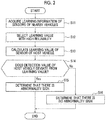
- FIG. 2 is a flowchart showing an example of a procedure of a diagnosis method using the diagnosis device 10.
- the diagnosis device 10 acquires learning information with respect to the sensors 30 mounted in the nearby vehicles 1-2, 1-3 through inter-vehicle communication (step S11). Then, the diagnosis device 10 selects a learning value with high reliability from the acquired learning information (step S12). A learning value of the sensor 30 mounted in the host vehicle 1-1 is calculated using the learning value with high reliability (step S13). The learning value of the sensor 30 indicates a value obtained by estimating a normal value of the detection value of the sensor 30. Specific examples of the processes of steps S12 and S13 will be described below. The process of step S12 can be omitted.
- the diagnosis device 10 compares the detection value of the sensor 30 mounted in the host vehicle 1-1 with the calculated learning value (step S14), and when both deviate (Yes in step S14), the diagnosis device 10 determines that there is an abnormality sign of the sensor 30 mounted in the host vehicle 1-1 (step S15), and when both do not deviate (No in step S14), the diagnosis device 10 determines that there is no abnormality sign of the sensor 30 mounted in the host vehicle 1-1 (step S16).
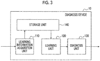
- FIG. 3 is a diagram illustrating a configuration example of the diagnosis device 10.
- the diagnosis device 10 illustrated in FIG. 3 includes a learning information acquisition unit 110, a learning unit 120, a diagnosis unit 130, and a storage unit 140.
- the learning information acquisition unit 110 performs the process of step S11 described above. That is, the learning information acquisition unit 110 instructs the inter-vehicle communication unit 40 to receive the learning information of the nearby vehicles 1-2, 1-3 through inter-vehicle communication.
- the learning information acquisition unit 110 acquires learning information of the sensors 30 mounted in the nearby vehicles 1-2, 1-3 from the inter-vehicle communication unit 40 and outputs the acquired learning information to the storage unit 140.
- the learning unit 120 performs the processes of steps S12 and S13 described above. That is, the learning unit 120 determines the reliability of the learning value included in the learning information stored in the storage unit 140, and discards the learning information including the learning value with low reliability. The learning unit 120 calculates a learning value of the sensor 30 mounted in the host vehicle 1-1 based on the learning value with high reliability, and outputs the calculated learning value to the diagnosis unit 130.
- the diagnosis unit 130 performs the processes of steps S14 to S16 described above. That is, for each sensor 30 mounted in the host vehicle 1-1, the diagnosis unit 130 compares the detection value of the sensor 30 with the learning value calculated by the learning unit 120. When a difference between both exceeds a preset threshold value (the detection value of the host vehicle 1-1 deviates from the learning value), the diagnosis unit 130 determines that there is an abnormality sign of the sensor 30. When the difference between both is equal to or smaller than the threshold value (the detection value of the host vehicle 1-1 does not deviate from the learning value), the diagnosis unit 130 determines that there is no abnormality sign of the sensor 30. The diagnosis unit 130 outputs a diagnosis result to the display unit 50, a speaker, an external server, or the like. When the diagnosis unit 130 determines that there is an abnormality sign of the sensor 30 of the host vehicle 1-1, the diagnosis unit 130 may not transmit the learning information of the sensor 30 to the nearby vehicles 1-2, 1-3.
- FIGS. 4A to 4C are diagrams illustrating specific examples of the diagnosis of the detection value in the diagnosis device 10.
- the host vehicle 1-1 newly receives the learning information of the sensor 30 from the nearby vehicles 1-2, 1-3.
- the learning value of the sensor 30 mounted in a certain vehicle is calculated based on the learning information of the sensors 30 mounted in nearby vehicles present in a predetermined range from the vehicle. That is, the learning value of the sensor 30 mounted in the host vehicle 1-1 is calculated based on the learning information of the sensors 30 mounted in the nearby vehicles 1-2, 1-3.
- the learning value of the sensor 30 mounted in the vehicle 1-2 is calculated based on the learning information of the sensor 30 mounted in the vehicle around the vehicle 1-2
- the learning value of the sensor 30 mounted in the vehicle 1-3 is calculated based on the learning information of the sensor 30 mounted in the vehicle around the vehicle 1-3.
- the learning value is a sum of the detection value and the error value.
- the learning value in the vehicle 1-1 may be represented as "detection value 21 °C, error value -1°C" instead of being represented as "20°C”.
- the learning unit 120 may discard the learning information when the error value exceeds the threshold value from among the learning information stored in the storage unit 140, and calculate the learning value of the sensor 30 mounted in the host vehicle 1-1 using the learning value in which the error value (a difference from the detection value) is equal to or smaller than the threshold value.
- the host vehicle 1-1 may not receive the learning information from the nearby vehicles 1-2, 1-3 from which the host vehicle 1-1 has once received the learning information, until a predetermined time or more has elapsed.
- an identification ID for identifying a vehicle may be included in the learning information, and the learning information acquisition unit 110 may discard newly acquired learning information when an identification ID included in the newly acquired learning information is the same as an identification ID included in learning information acquired in the past and a difference in acquisition time between the learning information is equal to or shorter than a predetermined time.
- the learning information is learning information with respect to the outside air temperature sensor 30, and in FIG. 4C , the learning information is learning information with respect to the oil temperature sensor 30.
- the learning unit 120 of the host vehicle 1-1 calculates the learning value of the outside air temperature sensor 30 mounted in the host vehicle 1-1 using the learning information acquired from the nearby vehicles 1-2, 1-3
- the number of vehicles 1 (the number of learning vehicles) related to the calculation of the learning value may be included in the learning information, and the learning value is associated with the number of learning vehicles, as illustrated in FIG. 4B .
- the learning information of the vehicle 1-2 indicates that the learning value "22°C" has been calculated using the learning information of the outside air temperature sensor 30 of "10" vehicles 1.
- the number of learning vehicles is "one"
- the initial value of the learning value is, for example, a detection value itself.
- the learning unit 120 may discard the learning value associated with the number of learning vehicles equal to or smaller than a threshold value among the learning values stored in the storage unit 140, and calculate the learning value of the sensor 30 mounted in the host vehicle 1-1 using the learning value associated with the number of learning vehicles exceeding the threshold value.
- the learning unit 120 of the host vehicle 1-1 calculates the learning value of the outside air temperature sensor 30 mounted in the host vehicle 1-1 using the learning information acquired from the nearby vehicles 1-2, 1-3
- the learning unit 120 sets a weighted average value obtained by weighting the learning value of the outside air temperature sensor 30 mounted in the host vehicle 1-1 and the nearby vehicles 1-2, 1-3 according to the number of learning vehicles, to the learning value of the outside air temperature sensor 30 mounted in the host vehicle 1-1.
- the learning unit 120 calculates a learning value x ⁇ of the sensor 30 mounted in the host vehicle 1-1 using Equation (1).
- x i is a learning value for the sensor 30 mounted in the vehicle 1-i
- w i is the number of learning vehicles with respect to the sensor 30 mounted in the vehicle 1-i.
- x ⁇ ⁇ i x i w i w i
- the number of learning vehicles increases each time learning is performed by acquiring the learning information from the nearby vehicles 1-2, 1-3. Therefore, when the number of learning vehicles of the host vehicle 1-1 exceeds the threshold value, the learning unit 120 may discard the first stored learning value among the learning values stored in the storage unit 140. Further, the storage unit 140 may delete old learning values for which a storage time has passed a predetermined time or more.
- the learning information stored in the storage unit 140 may be deleted and the learning value may be reset since an accurate value can be obtained as the learning value.
- means for enabling the vehicle 1 to acquire the normal value of the sensor 30, for example, by driving a verification vehicle that transmits learning information including a normal value (an accurate learning value) of the sensor 30 or disposing a base station that transmits learning information including the normal value of the sensor 30 can be provided.
- the vehicle 1 having received the normal value may delete the learning information stored in the storage unit 140 and reset the learning value.
- reliability information indicating that the reliability of the learning value is high may be included as the learning information, and the learning unit 120 may calculate the learning value in consideration of the reliability information.
- the sensor 30 When the sensor 30 is an outside air temperature sensor, it is difficult for the sensor 30 to be influenced by an environment other than an external environment. It is assumed that the external environment is similar between the host vehicle 1-1 and the nearby vehicles 1-2, 1-3. Therefore, for the outside air temperature sensor, learning can be performed using all the learning values of the nearby vehicles 1-2, 1-3. However, for example, since the normal values of the water temperature sensor, the oil temperature sensor, the atmospheric pressure sensor, and the like are different depending on an elapsed time after engine activation, it is desirable for learning to be performed using the learning values of the vehicles having a similar traveling environment among the nearby vehicles 1-2, 1-3. Therefore, a parameter indicating a traveling environment, such as an elapsed time after engine activation, may be included in the learning information, as illustrated in FIG. 4C , in order to make it possible to determine whether or not a traveling environment is similar.
- a parameter indicating a traveling environment such as an elapsed time after engine activation
- the learning unit 120 may discard the learning information when the difference in the parameter between the nearby vehicle and the host vehicle 1-1 exceeds the threshold value among the learning information stored in the storage unit 140 according to the type of sensor 30, and calculate the learning value of the sensor 30 mounted in the host vehicle 1-1 using the learning value in which the difference in the parameter between the nearby vehicle and the host vehicle 1-1 is equal to or smaller than the threshold value.
- the learning unit 120 of the host vehicle 1-1 discards the learning information with respect to the oil temperature sensor 30 acquired from the nearby vehicle 1-3 and calculates the learning value of the oil temperature sensor 30 mounted in the host vehicle 1-1 using the learning information acquired from the nearby vehicle 1-2.
- the learning values of the sensors 30 mounted in the nearby vehicles 1-2, 1-3 are acquired, and the learning value of the sensor 30 mounted in the host vehicle 1-1 present in the predetermined range from the nearby vehicles 1-2, 1-3 is calculated using the acquired learning values.
- the learning values of the nearby vehicles 1-2, 1-3 present in the predetermined range from the host vehicle 1-1 are acquired and the learning value of the sensor 30 mounted in the host vehicle 1-1 is calculated using the acquired learning values.
- An operation state of the sensor 30 mounted in the host vehicle 1-1 is diagnosed by comparing the detection value of the sensor 30 mounted in the host vehicle 1-1 with the learning value of the sensor 30. Therefore, according to the first embodiment of the present invention, it is possible to correctly estimate the normal value of the sensor 30, and to accurately diagnose the abnormality sign of the sensor 30 mounted in the host vehicle 1-1.
- the learning values acquired from the nearby vehicles 1-2, 1-3 are learning results based on learning information of a plurality of vehicles, for example, the number of learning vehicles increases from 5 to 20 by the vehicle 1-1 receiving the learning information from the nearby vehicles 1-2, 1-3 in the example illustrated in FIG. 4B . Therefore, according to the first embodiment of the present invention, even when the learning information is received from a small number of nearby vehicles 1-2, 1-3, it is possible to perform learning based on learning information of a substantially large number of vehicles, and to improve learning speed.
- diagnosis device 10 is mounted in each vehicle 1 has been shown in the first embodiment, but the diagnosis device 10 according to the second embodiment is included outside the vehicle 1.
- FIG. 5 is a diagram illustrating a schematic configuration of a system including the diagnosis device according to the second embodiment.
- Each vehicle 1 includes an ECU 20, a device (a sensor in the second embodiment) 30, a display unit 50, and a wide area communication unit 60.
- the server 2 includes a wide area communication unit 21 and a diagnosis device 10.
- the server 2 may be a cloud server or a data center.
- the wide area communication unit 60 modulates the learning information with respect to the sensor 30 mounted in the vehicle 1 using the radio waves in the frequency band assigned in advance and transmits the learning information to the server 2 via a wide area communication network.
- the wide area communication unit 21 receives the learning information with respect to the sensors 30 mounted in each vehicle 1 from each vehicle 1 via the wide area communication network using the radio waves in the frequency band assigned in advance, demodulates the learning information, and outputs the demodulated learning information to the diagnosis device 10.
- a diagnosis method according to the second embodiment is the same as the diagnosis method of the first embodiment described with reference to FIG. 2 .
- the host vehicle 1-1 means a diagnosis target vehicle
- the nearby vehicles 1-2, 1-3 mean vehicles present in a predetermined range from the diagnosis target vehicle 1-1.
- the learning information acquisition unit 110 acquires the learning information of the diagnosis target vehicle 1-1 and the nearby vehicles 1-2, 1-3 from the wide area communication unit 21, the learning unit 120 calculates the learning value based on the learning information of the diagnosis target vehicle 1-1 and the nearby vehicles 1-2, 1-3, and the diagnosis unit 130 compares a detection value of the diagnosis target vehicle 1-1 with the learning value of the diagnosis target vehicle 1-1 to diagnose an operation state of the sensor 30.
- a diagnosis result may be stored in the server 2 or may be output to the wide area communication unit 21 and transmitted to the diagnosis target vehicle 1-1.
- the diagnosis device 10 according to the second embodiment is disposed in the server 2 outside the vehicle. Therefore, according to the second embodiment of the present invention, it is possible to reduce an amount of communication and a calculation load in the vehicle 1. Further, it is possible to collectively manage a large amount of data of the vehicle 1 within the server 2.
- the diagnosis device 10 is disposed in each vehicle 1 and the server 2 so that both of each vehicle 1 and the server 2 can diagnose the sensor 30.
- FIG. 6 is a diagram illustrating a schematic configuration of the diagnosis system according to the third embodiment.
- Each vehicle 1 includes a diagnosis device 10, an ECU 20, a device (a sensor in the third embodiment) 30, an inter-vehicle communication unit 40, a display unit 50, and a wide area communication unit 60.
- the server 2 includes a wide area communication unit 21 and a diagnosis device 10.
- FIG. 7 is a flowchart showing an example of a procedure of a diagnosis method using the diagnosis system according to the third embodiment.
- the diagnosis device 10 on the vehicle 1 side acquires a diagnosis result of the diagnosis device 10 disposed in the server 2 from the server 2 (step S32).
- the wide area communication unit 60 when the wide area communication unit 60 has failed in communication with the server 2 due to radio wave failure or failure of the server 2 (No in step S31), the wide area communication unit 60 performs inter-vehicle communication with the nearby vehicles 1-2, 1-3 and acquires learning information of the sensors 30 of the nearby vehicles 1-2, 1-3 (step S11).
- a procedure from the acquisition of the learning information is the same as in the first embodiment, and the diagnosis device 10 selects a learning value with high reliability from the acquired learning information (step S12), and calculates the learning value of the sensor 30 of the host vehicle 1-1 using the learning value with high reliability (step S13).
- the diagnosis device 10 compares the detection value of the host vehicle 1-1 with the calculated learning value (step S14). When both deviate from each other (Yes in step S14), the diagnosis device 10 determines that there is an abnormality sign of the sensor 30 mounted in the host vehicle 1-1 (step S15). When both do not deviate from each other (No in step S14), the diagnosis device 10 determines that there is no abnormality sign of the sensor 30 mounted in the host vehicle 1-1 (step S16).
- the learning information acquisition unit 110 of the diagnosis device 10 on the vehicle 1 side performs the processes of steps S31, S32, and S11 described above. That is, the learning information acquisition unit 110 instructs the wide area communication unit 60 to receive the learning information of the nearby vehicles 1-2, 1-3 through communication with the server 2. When the wide area communication unit 60 has failed in communication, the learning information acquisition unit 110 instructs the inter-vehicle communication unit 40 to receive the learning information of the nearby vehicles 1-2, 1-3 through inter-vehicle communication. The learning information acquisition unit 110 acquires the learning information from the inter-vehicle communication unit 40, and outputs the acquired learning value to the storage unit 140.
- the learning unit 120 of the diagnosis device 10 on the vehicle 1 side performs the process of the above step S12, as in the first embodiment. That is, the learning unit 120 calculates the learning value of the host vehicle 1-1 based on the learning information input from the learning information acquisition unit 110, and outputs the calculated learning value to the diagnosis unit 130.
- the diagnosis unit 130 of the diagnosis device 10 on the vehicle 1 side performs the processes of steps S13 to S15, as in the first embodiment. That is, the diagnosis unit 130 compares the detection value of the host vehicle 1-1 with the learning value input from the learning unit 120 for each sensor 30, determines that there is an abnormality sign of the sensor 30 when a difference between both exceeds a preset threshold value, and determines that there is no abnormality sign of the sensor 30 when the difference between both is equal to or smaller than the threshold value.
- the diagnosis unit 130 may output the diagnosis result to the display unit 50, the speaker, or the like in the vehicle or may output the diagnosis result to the server 2.
- the diagnosis device 10 on the vehicle 1 side acquires the learning information of the nearby vehicles 1-2, 1-3 through the inter-vehicle communication solely when the vehicle 1 has failed in communication with the server 2. Therefore, according to the third embodiment of the present invention, it is possible to reduce an amount of communication and a calculation load in the vehicle 1 and to collectively manage a large amount of data of the vehicle 1 within the server 2. Further, even when the vehicle 1 has failed in communication with the server 2, it is possible to acquire the learning information of the nearby vehicles 1-2, 1-3 through inter-vehicle communication and to perform the diagnosis of the sensor 30 mounted in the host vehicle 1-1.
- a computer can also be used for a function as the diagnosis device 10.
- Such a computer can be realized by storing a program describing processing content for realizing each function of the diagnosis device 10 in a storage unit of the computer, and reading and executing the program using a central processing unit (CPU) of the computer.
- CPU central processing unit
- the program may be recorded in a computer-readable medium.
- the program can be installed in the computer.
- the computer-readable medium on which the program has been recorded may be a non-transitory recording medium.
- the non-transitory recording medium is not particularly limited and may be a recording medium such as a compact disc-read only memory (CD-ROM) or a digital versatile disc-read only memory (DVD-ROM).
Landscapes
- Engineering & Computer Science (AREA)
- Physics & Mathematics (AREA)
- General Physics & Mathematics (AREA)
- Automation & Control Theory (AREA)
- Computer Networks & Wireless Communication (AREA)
- Signal Processing (AREA)
- Theoretical Computer Science (AREA)
- Software Systems (AREA)
- Data Mining & Analysis (AREA)
- Evolutionary Computation (AREA)
- Medical Informatics (AREA)
- Computer Vision & Pattern Recognition (AREA)
- Computing Systems (AREA)
- General Engineering & Computer Science (AREA)
- Mathematical Physics (AREA)
- Artificial Intelligence (AREA)
- Traffic Control Systems (AREA)
Abstract
Description
- The present invention relates to a diagnosis device and a diagnosis method for diagnosing an abnormality sign of a device mounted in a vehicle.
- Technologies for diagnosing an abnormality sign of a device have been developed. For example, Japanese Unexamined Patent Application Publication No.
2016-157206 JP 2016-157206 A - The technology described in
JP 2016-157206 A - The present invention provides a diagnosis device and a diagnosis method capable of accurately diagnosing an abnormality sign of a device mounted in a vehicle.
- A first aspect of the present invention relates to a diagnosis device. The diagnosis device includes a learning information acquisition unit configured to acquire a learning value of a first device mounted in at least one first vehicle present in a predetermined range from a second vehicle; a learning unit configured to calculate a learning value of a second device mounted in the second vehicle using the learning value of the first device; and a diagnosis unit configured to diagnose an operation state of the second device by comparing a detection value of the second device with the learning value of the second device.
- In the diagnosis device according to the first aspect, the learning unit may be configured to calculate the learning value of the second device using the learning value of the first device when a difference between a detection value of the first device and the learning value of the first device is equal to or smaller than a threshold value.
- In the diagnosis device according to the first aspect, the learning value of the first device may be calculated based on a learning value of a third device mounted in at least one third vehicle present in a predetermined range from the first vehicle; the learning information acquisition unit may be configured to acquire the learning value of the first device and the number of learning vehicles indicating the number of the third vehicles related to the calculation of the learning value of the first device in association with each other; and the learning unit may be configured to calculate the learning value of the second device using the learning value of the first device and the number of learning vehicles.
- In the diagnosis device according to the aspect, the learning unit may be configured to calculate the learning value of the second device using the learning value of the first device when the number of learning vehicles associated with the learning value of the first device exceeds a threshold value.
- In the diagnosis device according to the aspect, the learning unit may be configured to calculate a weighted average obtained by weighting the learning values of the first device according to the number of learning vehicles, as the learning value of the second device.
- In the diagnosis device according to the first aspect, the learning unit may be configured to reset the learning value of the second device when the second vehicle is repaired or inspected.
- A second aspect of the present invention relates to a diagnosis method. The diagnosis method includes acquiring a learning value of a first device mounted in a first vehicle; calculating a learning value of a second device mounted in a second vehicle present in a predetermined range from the first vehicle using the learning value of the first device; and diagnosing an operation state of the second device by comparing a detection value of the second device with the learning value of the second device.
- According to each aspect of the present invention, it is possible to accurately diagnose an abnormality sign of a device mounted in a vehicle.
- Features, advantages, and technical and industrial significance of exemplary embodiments of the invention will be described below with reference to the accompanying drawings, in which like numerals denote like elements, and wherein:
-
FIG. 1 is a diagram illustrating a schematic configuration of a vehicle including a diagnosis device according to a first embodiment of the present invention; -
FIG. 2 is a flowchart showing an example of a procedure of a diagnosis method using the diagnosis device according to the first embodiment of the present invention; -
FIG. 3 is a diagram illustrating a configuration example of the diagnosis device according to the first embodiment of the present invention; -
FIG. 4A is a diagram illustrating a diagnosis example by a diagnosis device according to the first embodiment of the present invention; -
FIG. 4B is a diagram illustrating a diagnosis example by the diagnosis device according to the first embodiment of the present invention; -
FIG. 4C is a diagram illustrating a diagnosis example by the diagnosis device according to the first embodiment of the present invention; -
FIG. 5 is a diagram illustrating a schematic configuration of a system including a diagnosis device according to a second embodiment of the present invention; -
FIG. 6 is a diagram illustrating a schematic configuration of a diagnosis system according to a third embodiment of the present invention; and -
FIG. 7 is a flowchart showing an example of a procedure of a diagnosis method using the diagnosis system according to the third embodiment of the present invention. - Hereinafter, embodiments of the present invention will be described in detail with reference to the drawings.
-
FIG. 1 is a diagram illustrating a schematic configuration of a vehicle including a diagnosis device according to a first embodiment. Each vehicle 1 includes adiagnosis device 10, an electronic control unit (ECU) 20, adevice 30, aninter-vehicle communication unit 40, and adisplay unit 50. For convenience of description, inFIG. 1 , solely three vehicles 1-1, 1-2, 1-3 having the same configuration are illustrated. In the first embodiment, the vehicle 1-1 is referred to as a host vehicle (an example of a second vehicle), and the vehicle 1-2 and the vehicle 1-3 are nearby vehicles (examples of a first vehicle) present in a predetermined range from the vehicle 1-1. Here, the predetermined range is, for example, a range in which inter-vehicle communication is possible. - Since a sensor deteriorates over time, a detection value of the sensor may gradually deviate from a normal value, so that a control value of an actuator based on the detection value of the sensor also deviates from a normal value. Therefore, in the present invention, the detection value of the sensor or the control value of the actuator is monitored so as to diagnose the sensor.
- The
device 30 is a sensor or an actuator, and a detection value of thedevice 30 means a detection value (a sensor value) of the sensor or the control value of the actuator. Hereinafter, in the embodiment of the present specification, thedevice 30 will be described as thesensor 30.Various sensors 30 such as an outside air temperature sensor, an intake air temperature sensor, a water temperature sensor, a vehicle speed sensor, an O2 sensor, a steering sensor, an air pressure sensor, an ultrasonic sensor, a gyro sensor, and an obstacle sensor are mounted in the vehicle 1. The detection value of thesensor 30 is output to theECU 20 that performs a process using the detection value. - A plurality of
ECUs 20 is mounted in the vehicle 1 and electronically controls various operations of the vehicle 1. For example, theECU 20 for an engine drives the actuator based on information from thesensors 30 such as the intake temperature sensor, the water temperature sensor, the vehicle speed sensor, the O2 sensor, and the like, and controls an amount of fuel injection or an injection time of the engine. - The
inter-vehicle communication unit 40 performs direct communication (inter-vehicle communication) between the vehicles 1 using radio waves in a frequency band assigned in advance, and receives and demodulates learning information of the sensor 30 (a first device) mounted in the nearby vehicles 1-2, 1-3 from the nearby vehicles 1-2, 1-3. Further, theinter-vehicle communication unit 40 modulates learning information of the sensor 30 (a second device) mounted in the host vehicle 1-1 and transmits the learning information to the nearby vehicles 1-2, 1-3. Theinter-vehicle communication unit 40 is capable of communicating with nearby vehicles present in a coverage of the radio waves. The coverage of the radio waves can be appropriately adjusted by adjusting intensity of the radio waves. Theinter-vehicle communication unit 40 outputs the received learning information to thediagnosis device 10. Theinter-vehicle communication unit 40 transmits and receives the learning information at any frequency. Onceinter-vehicle communication unit 40 performs the communication with the same vehicle, theinter-vehicle communication unit 40 may not perform communication until a predetermined period of time elapses in order to restrict communication with the same vehicle many time. - The
diagnosis device 10 determines whether or not there is a sign of abnormality such as a failure of thesensor 30 mounted in the host vehicle 1-1 based on the learning information received by theinter-vehicle communication unit 40 through inter-vehicle communication. - The
display unit 50 is, for example, a panel display or a head up display, and displays a diagnosis result or the like of thediagnosis device 10. - Processing content of the
diagnosis device 10 will be described in greater detail with reference toFIGS. 3 and4A to 4C after an overview is described with reference toFIG. 2. FIG. 2 is a flowchart showing an example of a procedure of a diagnosis method using thediagnosis device 10. - The
diagnosis device 10 acquires learning information with respect to thesensors 30 mounted in the nearby vehicles 1-2, 1-3 through inter-vehicle communication (step S11). Then, thediagnosis device 10 selects a learning value with high reliability from the acquired learning information (step S12). A learning value of thesensor 30 mounted in the host vehicle 1-1 is calculated using the learning value with high reliability (step S13). The learning value of thesensor 30 indicates a value obtained by estimating a normal value of the detection value of thesensor 30. Specific examples of the processes of steps S12 and S13 will be described below. The process of step S12 can be omitted. - The
diagnosis device 10 compares the detection value of thesensor 30 mounted in the host vehicle 1-1 with the calculated learning value (step S14), and when both deviate (Yes in step S14), thediagnosis device 10 determines that there is an abnormality sign of thesensor 30 mounted in the host vehicle 1-1 (step S15), and when both do not deviate (No in step S14), thediagnosis device 10 determines that there is no abnormality sign of thesensor 30 mounted in the host vehicle 1-1 (step S16). -
FIG. 3 is a diagram illustrating a configuration example of thediagnosis device 10. Thediagnosis device 10 illustrated inFIG. 3 includes a learninginformation acquisition unit 110, alearning unit 120, adiagnosis unit 130, and astorage unit 140. - The learning
information acquisition unit 110 performs the process of step S11 described above. That is, the learninginformation acquisition unit 110 instructs theinter-vehicle communication unit 40 to receive the learning information of the nearby vehicles 1-2, 1-3 through inter-vehicle communication. The learninginformation acquisition unit 110 acquires learning information of thesensors 30 mounted in the nearby vehicles 1-2, 1-3 from theinter-vehicle communication unit 40 and outputs the acquired learning information to thestorage unit 140. - The
learning unit 120 performs the processes of steps S12 and S13 described above. That is, thelearning unit 120 determines the reliability of the learning value included in the learning information stored in thestorage unit 140, and discards the learning information including the learning value with low reliability. Thelearning unit 120 calculates a learning value of thesensor 30 mounted in the host vehicle 1-1 based on the learning value with high reliability, and outputs the calculated learning value to thediagnosis unit 130. - The
diagnosis unit 130 performs the processes of steps S14 to S16 described above. That is, for eachsensor 30 mounted in the host vehicle 1-1, thediagnosis unit 130 compares the detection value of thesensor 30 with the learning value calculated by thelearning unit 120. When a difference between both exceeds a preset threshold value (the detection value of the host vehicle 1-1 deviates from the learning value), thediagnosis unit 130 determines that there is an abnormality sign of thesensor 30. When the difference between both is equal to or smaller than the threshold value (the detection value of the host vehicle 1-1 does not deviate from the learning value), thediagnosis unit 130 determines that there is no abnormality sign of thesensor 30. Thediagnosis unit 130 outputs a diagnosis result to thedisplay unit 50, a speaker, an external server, or the like. When thediagnosis unit 130 determines that there is an abnormality sign of thesensor 30 of the host vehicle 1-1, thediagnosis unit 130 may not transmit the learning information of thesensor 30 to the nearby vehicles 1-2, 1-3. -
FIGS. 4A to 4C are diagrams illustrating specific examples of the diagnosis of the detection value in thediagnosis device 10. In the example illustrated inFIGS. 4A to 4C , it is assumed that the host vehicle 1-1 newly receives the learning information of thesensor 30 from the nearby vehicles 1-2, 1-3. The learning value of thesensor 30 mounted in a certain vehicle is calculated based on the learning information of thesensors 30 mounted in nearby vehicles present in a predetermined range from the vehicle. That is, the learning value of thesensor 30 mounted in the host vehicle 1-1 is calculated based on the learning information of thesensors 30 mounted in the nearby vehicles 1-2, 1-3. Further, the learning value of thesensor 30 mounted in the vehicle 1-2 is calculated based on the learning information of thesensor 30 mounted in the vehicle around the vehicle 1-2, and the learning value of thesensor 30 mounted in the vehicle 1-3 is calculated based on the learning information of thesensor 30 mounted in the vehicle around the vehicle 1-3. - When the detection value of the
sensor 30 is X and the learning value is Y, information on the error value may be included in the learning value, and the error value may be expressed as "detection value X, error value (Y - X)". That is, the learning value is a sum of the detection value and the error value. For example, inFIG. 4A , the learning value in the vehicle 1-1 may be represented as "detection value 21 °C, error value -1°C" instead of being represented as "20°C". By including the information on the error value, it can be estimated that reliability of the learning value is likely to be low when the error value is great. Therefore, thelearning unit 120 may discard the learning information when the error value exceeds the threshold value from among the learning information stored in thestorage unit 140, and calculate the learning value of thesensor 30 mounted in the host vehicle 1-1 using the learning value in which the error value (a difference from the detection value) is equal to or smaller than the threshold value. - The host vehicle 1-1 may not receive the learning information from the nearby vehicles 1-2, 1-3 from which the host vehicle 1-1 has once received the learning information, until a predetermined time or more has elapsed. For example, an identification ID for identifying a vehicle may be included in the learning information, and the learning
information acquisition unit 110 may discard newly acquired learning information when an identification ID included in the newly acquired learning information is the same as an identification ID included in learning information acquired in the past and a difference in acquisition time between the learning information is equal to or shorter than a predetermined time. - In
FIGS. 4A and 4B , the learning information is learning information with respect to the outsideair temperature sensor 30, and inFIG. 4C , the learning information is learning information with respect to theoil temperature sensor 30. InFIG. 4A , when thelearning unit 120 of the host vehicle 1-1 calculates the learning value of the outsideair temperature sensor 30 mounted in the host vehicle 1-1 using the learning information acquired from the nearby vehicles 1-2, 1-3, thelearning unit 120 sets the learning value of the outsideair temperature sensor 30 mounted in the host vehicle 1-1 to, for example, an average value of learning values (22 + 20 + 24)/3 = 22[°C] of the outsideair temperature sensor 30 mounted in the host vehicle 1-1 and the nearby vehicles 1-2, 1-3. - Further, the number of vehicles 1 (the number of learning vehicles) related to the calculation of the learning value may be included in the learning information, and the learning value is associated with the number of learning vehicles, as illustrated in
FIG. 4B . The learning information of the vehicle 1-2 indicates that the learning value "22°C" has been calculated using the learning information of the outsideair temperature sensor 30 of "10" vehicles 1. When the number of learning vehicles is "one", this indicates that the learning value is an initial value or a value after resetting. The initial value of the learning value is, for example, a detection value itself. - When the number of learning vehicles is small, the reliability of the learning value is likely to be low. Therefore, the
learning unit 120 may discard the learning value associated with the number of learning vehicles equal to or smaller than a threshold value among the learning values stored in thestorage unit 140, and calculate the learning value of thesensor 30 mounted in the host vehicle 1-1 using the learning value associated with the number of learning vehicles exceeding the threshold value. - In
FIG. 4B , when thelearning unit 120 of the host vehicle 1-1 calculates the learning value of the outsideair temperature sensor 30 mounted in the host vehicle 1-1 using the learning information acquired from the nearby vehicles 1-2, 1-3, thelearning unit 120 sets a weighted average value obtained by weighting the learning value of the outsideair temperature sensor 30 mounted in the host vehicle 1-1 and the nearby vehicles 1-2, 1-3 according to the number of learning vehicles, to the learning value of the outsideair temperature sensor 30 mounted in the host vehicle 1-1. For example, thelearning unit 120 calculates a learning value x^ of thesensor 30 mounted in the host vehicle 1-1 using Equation (1). xi is a learning value for thesensor 30 mounted in the vehicle 1-i, and wi is the number of learning vehicles with respect to thesensor 30 mounted in the vehicle 1-i. In the example ofFIG. 4B , when Equation (1) is used, the learning value x^ after learning is (20 × 5 + 22 × 10 + 24 × 5)/(5 + 10 + 5) = 22[°C] for the outsideair temperature sensor 30 mounted in the vehicle 1-1.
- In
FIG. 4B , the number of learning vehicles after learning of the host vehicle 1-1 is 5 + 10 + 5 = 20. The number of learning vehicles increases each time learning is performed by acquiring the learning information from the nearby vehicles 1-2, 1-3. Therefore, when the number of learning vehicles of the host vehicle 1-1 exceeds the threshold value, thelearning unit 120 may discard the first stored learning value among the learning values stored in thestorage unit 140. Further, thestorage unit 140 may delete old learning values for which a storage time has passed a predetermined time or more. - Further, when repair or an inspection (vehicle inspection) based on an automobile inspection registration system is performed, the learning information stored in the
storage unit 140 may be deleted and the learning value may be reset since an accurate value can be obtained as the learning value. Further, means for enabling the vehicle 1 to acquire the normal value of thesensor 30, for example, by driving a verification vehicle that transmits learning information including a normal value (an accurate learning value) of thesensor 30 or disposing a base station that transmits learning information including the normal value of thesensor 30 can be provided. The vehicle 1 having received the normal value may delete the learning information stored in thestorage unit 140 and reset the learning value. When the accurate learning value of thesensor 30 has been acquired, reliability information indicating that the reliability of the learning value is high may be included as the learning information, and thelearning unit 120 may calculate the learning value in consideration of the reliability information. - When the
sensor 30 is an outside air temperature sensor, it is difficult for thesensor 30 to be influenced by an environment other than an external environment. It is assumed that the external environment is similar between the host vehicle 1-1 and the nearby vehicles 1-2, 1-3. Therefore, for the outside air temperature sensor, learning can be performed using all the learning values of the nearby vehicles 1-2, 1-3. However, for example, since the normal values of the water temperature sensor, the oil temperature sensor, the atmospheric pressure sensor, and the like are different depending on an elapsed time after engine activation, it is desirable for learning to be performed using the learning values of the vehicles having a similar traveling environment among the nearby vehicles 1-2, 1-3. Therefore, a parameter indicating a traveling environment, such as an elapsed time after engine activation, may be included in the learning information, as illustrated inFIG. 4C , in order to make it possible to determine whether or not a traveling environment is similar. - The reliability of the learning value of the nearby vehicle having a large difference in parameter between the nearby vehicle and the host vehicle 1-1 is likely to be low according to a type of
sensor 30. Therefore, thelearning unit 120 may discard the learning information when the difference in the parameter between the nearby vehicle and the host vehicle 1-1 exceeds the threshold value among the learning information stored in thestorage unit 140 according to the type ofsensor 30, and calculate the learning value of thesensor 30 mounted in the host vehicle 1-1 using the learning value in which the difference in the parameter between the nearby vehicle and the host vehicle 1-1 is equal to or smaller than the threshold value. - For example, in
FIG. 4C , since the difference in the parameter between the host vehicle 1-1 and the nearby vehicle 1-3 is great, thelearning unit 120 of the host vehicle 1-1 discards the learning information with respect to theoil temperature sensor 30 acquired from the nearby vehicle 1-3 and calculates the learning value of theoil temperature sensor 30 mounted in the host vehicle 1-1 using the learning information acquired from the nearby vehicle 1-2. With Equation (1) is used, the learning value x^ for theoil temperature sensor 30 mounted in the vehicle 1-1 is (92 × 8 + 90 × 5)/(8 + 5) = 91.2[°C], and the number of learning vehicles is 8 + 5 = 13. - Thus, in the
diagnosis device 10 and the diagnosis method according to the first embodiment, the learning values of thesensors 30 mounted in the nearby vehicles 1-2, 1-3 are acquired, and the learning value of thesensor 30 mounted in the host vehicle 1-1 present in the predetermined range from the nearby vehicles 1-2, 1-3 is calculated using the acquired learning values. In other words, the learning values of the nearby vehicles 1-2, 1-3 present in the predetermined range from the host vehicle 1-1 are acquired and the learning value of thesensor 30 mounted in the host vehicle 1-1 is calculated using the acquired learning values. An operation state of thesensor 30 mounted in the host vehicle 1-1 is diagnosed by comparing the detection value of thesensor 30 mounted in the host vehicle 1-1 with the learning value of thesensor 30. Therefore, according to the first embodiment of the present invention, it is possible to correctly estimate the normal value of thesensor 30, and to accurately diagnose the abnormality sign of thesensor 30 mounted in the host vehicle 1-1. - Further, it is possible to diagnose an abnormality sign of the
sensor 30 mounted in the host vehicle 1-1 with higher accuracy by selecting the learning value with high reliability from among the learning information acquired from the nearby vehicles 1-2, 1-3 and calculating the learning value of thesensor 30 mounted in the vehicle 1-1 using the selected learning value. - Further, since the learning values acquired from the nearby vehicles 1-2, 1-3 are learning results based on learning information of a plurality of vehicles, for example, the number of learning vehicles increases from 5 to 20 by the vehicle 1-1 receiving the learning information from the nearby vehicles 1-2, 1-3 in the example illustrated in
FIG. 4B . Therefore, according to the first embodiment of the present invention, even when the learning information is received from a small number of nearby vehicles 1-2, 1-3, it is possible to perform learning based on learning information of a substantially large number of vehicles, and to improve learning speed. - Next, a diagnosis device according to a second embodiment will be described. The example in which the
diagnosis device 10 is mounted in each vehicle 1 has been shown in the first embodiment, but thediagnosis device 10 according to the second embodiment is included outside the vehicle 1. -
FIG. 5 is a diagram illustrating a schematic configuration of a system including the diagnosis device according to the second embodiment. Each vehicle 1 includes anECU 20, a device (a sensor in the second embodiment) 30, adisplay unit 50, and a widearea communication unit 60. Theserver 2 includes a widearea communication unit 21 and adiagnosis device 10. Theserver 2 may be a cloud server or a data center. - The wide
area communication unit 60 modulates the learning information with respect to thesensor 30 mounted in the vehicle 1 using the radio waves in the frequency band assigned in advance and transmits the learning information to theserver 2 via a wide area communication network. - The wide
area communication unit 21 receives the learning information with respect to thesensors 30 mounted in each vehicle 1 from each vehicle 1 via the wide area communication network using the radio waves in the frequency band assigned in advance, demodulates the learning information, and outputs the demodulated learning information to thediagnosis device 10. - A diagnosis method according to the second embodiment is the same as the diagnosis method of the first embodiment described with reference to
FIG. 2 . Note that, in the second embodiment, the host vehicle 1-1 means a diagnosis target vehicle, and the nearby vehicles 1-2, 1-3 mean vehicles present in a predetermined range from the diagnosis target vehicle 1-1. - When the
diagnosis device 10 performs diagnosis of thesensor 30 mounted in the vehicle 1-1, the learninginformation acquisition unit 110 acquires the learning information of the diagnosis target vehicle 1-1 and the nearby vehicles 1-2, 1-3 from the widearea communication unit 21, thelearning unit 120 calculates the learning value based on the learning information of the diagnosis target vehicle 1-1 and the nearby vehicles 1-2, 1-3, and thediagnosis unit 130 compares a detection value of the diagnosis target vehicle 1-1 with the learning value of the diagnosis target vehicle 1-1 to diagnose an operation state of thesensor 30. A diagnosis result may be stored in theserver 2 or may be output to the widearea communication unit 21 and transmitted to the diagnosis target vehicle 1-1. - Thus, the
diagnosis device 10 according to the second embodiment is disposed in theserver 2 outside the vehicle. Therefore, according to the second embodiment of the present invention, it is possible to reduce an amount of communication and a calculation load in the vehicle 1. Further, it is possible to collectively manage a large amount of data of the vehicle 1 within theserver 2. - Next, a diagnosis system according to a third embodiment will be described. In the diagnosis system according to the third embodiment, the
diagnosis device 10 is disposed in each vehicle 1 and theserver 2 so that both of each vehicle 1 and theserver 2 can diagnose thesensor 30. -
FIG. 6 is a diagram illustrating a schematic configuration of the diagnosis system according to the third embodiment. Each vehicle 1 includes adiagnosis device 10, anECU 20, a device (a sensor in the third embodiment) 30, aninter-vehicle communication unit 40, adisplay unit 50, and a widearea communication unit 60. Theserver 2 includes a widearea communication unit 21 and adiagnosis device 10. - Processing content of the
diagnosis device 10 mounted in the vehicle 1 will be described with reference toFIG. 7. FIG. 7 is a flowchart showing an example of a procedure of a diagnosis method using the diagnosis system according to the third embodiment. - When the wide
area communication unit 60 succeeds in communication with the server 2 (Yes in step S31), thediagnosis device 10 on the vehicle 1 side acquires a diagnosis result of thediagnosis device 10 disposed in theserver 2 from the server 2 (step S32). - On the other hand, when the wide
area communication unit 60 has failed in communication with theserver 2 due to radio wave failure or failure of the server 2 (No in step S31), the widearea communication unit 60 performs inter-vehicle communication with the nearby vehicles 1-2, 1-3 and acquires learning information of thesensors 30 of the nearby vehicles 1-2, 1-3 (step S11). - A procedure from the acquisition of the learning information is the same as in the first embodiment, and the
diagnosis device 10 selects a learning value with high reliability from the acquired learning information (step S12), and calculates the learning value of thesensor 30 of the host vehicle 1-1 using the learning value with high reliability (step S13). Thediagnosis device 10 compares the detection value of the host vehicle 1-1 with the calculated learning value (step S14). When both deviate from each other (Yes in step S14), thediagnosis device 10 determines that there is an abnormality sign of thesensor 30 mounted in the host vehicle 1-1 (step S15). When both do not deviate from each other (No in step S14), thediagnosis device 10 determines that there is no abnormality sign of thesensor 30 mounted in the host vehicle 1-1 (step S16). - The learning
information acquisition unit 110 of thediagnosis device 10 on the vehicle 1 side performs the processes of steps S31, S32, and S11 described above. That is, the learninginformation acquisition unit 110 instructs the widearea communication unit 60 to receive the learning information of the nearby vehicles 1-2, 1-3 through communication with theserver 2. When the widearea communication unit 60 has failed in communication, the learninginformation acquisition unit 110 instructs theinter-vehicle communication unit 40 to receive the learning information of the nearby vehicles 1-2, 1-3 through inter-vehicle communication. The learninginformation acquisition unit 110 acquires the learning information from theinter-vehicle communication unit 40, and outputs the acquired learning value to thestorage unit 140. - The
learning unit 120 of thediagnosis device 10 on the vehicle 1 side performs the process of the above step S12, as in the first embodiment. That is, thelearning unit 120 calculates the learning value of the host vehicle 1-1 based on the learning information input from the learninginformation acquisition unit 110, and outputs the calculated learning value to thediagnosis unit 130. - The
diagnosis unit 130 of thediagnosis device 10 on the vehicle 1 side performs the processes of steps S13 to S15, as in the first embodiment. That is, thediagnosis unit 130 compares the detection value of the host vehicle 1-1 with the learning value input from thelearning unit 120 for eachsensor 30, determines that there is an abnormality sign of thesensor 30 when a difference between both exceeds a preset threshold value, and determines that there is no abnormality sign of thesensor 30 when the difference between both is equal to or smaller than the threshold value. Thediagnosis unit 130 may output the diagnosis result to thedisplay unit 50, the speaker, or the like in the vehicle or may output the diagnosis result to theserver 2. - Thus, in the diagnosis system according to the third embodiment, the
diagnosis device 10 on the vehicle 1 side acquires the learning information of the nearby vehicles 1-2, 1-3 through the inter-vehicle communication solely when the vehicle 1 has failed in communication with theserver 2. Therefore, according to the third embodiment of the present invention, it is possible to reduce an amount of communication and a calculation load in the vehicle 1 and to collectively manage a large amount of data of the vehicle 1 within theserver 2. Further, even when the vehicle 1 has failed in communication with theserver 2, it is possible to acquire the learning information of the nearby vehicles 1-2, 1-3 through inter-vehicle communication and to perform the diagnosis of thesensor 30 mounted in the host vehicle 1-1. - A computer can also be used for a function as the
diagnosis device 10. Such a computer can be realized by storing a program describing processing content for realizing each function of thediagnosis device 10 in a storage unit of the computer, and reading and executing the program using a central processing unit (CPU) of the computer. - Further, the program may be recorded in a computer-readable medium. When a computer-readable medium is used, the program can be installed in the computer. Here, the computer-readable medium on which the program has been recorded may be a non-transitory recording medium. The non-transitory recording medium is not particularly limited and may be a recording medium such as a compact disc-read only memory (CD-ROM) or a digital versatile disc-read only memory (DVD-ROM).
- Although the embodiments have been described as representative examples, it will be apparent to those skilled in the art that many changes and substitutions can be made within the spirit and scope of the present invention. Accordingly, the present invention is not construed as being limited by the above-described embodiments, and various modifications or changes are possible without departing from the scope of the claims. For example, it is possible to combine a plurality of constituent blocks or steps described in configuration diagrams of the embodiments into one or to divide one constituent block or step.
Claims (7)
- A diagnosis device (10) comprising:a learning information acquisition unit (110) configured to acquire a learning value of a first device (30) mounted in at least one first vehicle (1-2, 1-3) present in a predetermined range from a second vehicle (1-1);a learning unit (120) configured to calculate a learning value of a second device (30) mounted in the second vehicle (1-1) using the learning value of the first device (30); anda diagnosis unit (130) configured to diagnose an operation state of the second device (30) by comparing a detection value of the second device (30) with the learning value of the second device (30).
- The diagnosis device (10) according to claim 1, wherein the learning unit (120) is configured to calculate the learning value of the second device (30) using the learning value of the first device (30) when a difference between a detection value of the first device (30) and the learning value of the first device (30) is equal to or smaller than a threshold value.
- The diagnosis device (10) according to claim 1 or 2, wherein:the learning value of the first device (30) is calculated based on a learning value of a third device mounted in at least one third vehicle present in a predetermined range from the first vehicle (1-2, 1-3);the learning information acquisition unit (110) is configured to acquire the learning value of the first device (30) and the number of learning vehicles indicating the number of the third vehicles related to the calculation of the learning value of the first device (30) in association with each other; andthe learning unit (120) is configured to calculate the learning value of the second device (30) using the learning value of the first device (30) and the number of learning vehicles.
- The diagnosis device (10) according to claim 3, wherein the learning unit (120) is configured to calculate the learning value of the second device (30) using the learning value of the first device (30) when the number of learning vehicles associated with the learning value of the first device (30) exceeds a threshold value.
- The diagnosis device (10) according to claim 3, wherein the learning unit (120) is configured to calculate a weighted average obtained by weighting the learning values of the first device (30) according to the number of learning vehicles, as the learning value of the second device (30).
- The diagnosis device (10) according to any one of claims 1 to 5, wherein the learning unit (120) is configured to reset the learning value of the second device (30) when the second vehicle (1-1) is repaired or inspected.
- A diagnosis method comprising:acquiring a learning value of a first device (30) mounted in a first vehicle (1-2, 1-3);calculating a learning value of a second device (30) mounted in a second vehicle (1-1) present in a predetermined range from the first vehicle (1-2, 1-3) using the learning value of the first device (30); anddiagnosing an operation state of the second device (30) by comparing a detection value of the second device (30) with the learning value of the second device (30).
Applications Claiming Priority (1)
| Application Number | Priority Date | Filing Date | Title |
|---|---|---|---|
| JP2018058559A JP7013993B2 (en) | 2018-03-26 | 2018-03-26 | Diagnostic device and diagnostic method |
Publications (2)
| Publication Number | Publication Date |
|---|---|
| EP3547058A1 true EP3547058A1 (en) | 2019-10-02 |
| EP3547058B1 EP3547058B1 (en) | 2022-06-29 |
Family
ID=65861208
Family Applications (1)
| Application Number | Title | Priority Date | Filing Date |
|---|---|---|---|
| EP19162647.2A Active EP3547058B1 (en) | 2018-03-26 | 2019-03-13 | Diagnosis device and diagnosis method |
Country Status (4)
| Country | Link |
|---|---|
| US (1) | US11132851B2 (en) |
| EP (1) | EP3547058B1 (en) |
| JP (1) | JP7013993B2 (en) |
| CN (1) | CN110362059B (en) |
Families Citing this family (4)
| Publication number | Priority date | Publication date | Assignee | Title |
|---|---|---|---|---|
| JP7013993B2 (en) * | 2018-03-26 | 2022-02-01 | トヨタ自動車株式会社 | Diagnostic device and diagnostic method |
| JP6962435B1 (en) * | 2020-10-12 | 2021-11-05 | トヨタ自動車株式会社 | Machine learning device |
| JP2022163997A (en) * | 2021-04-15 | 2022-10-27 | 日野自動車株式会社 | Vehicle inspection device |
| CN114706372A (en) * | 2022-04-18 | 2022-07-05 | 中国第一汽车股份有限公司 | A test method, device, equipment and storage medium |
Citations (6)
| Publication number | Priority date | Publication date | Assignee | Title |
|---|---|---|---|---|
| US20080189009A1 (en) * | 2007-02-01 | 2008-08-07 | Gm Global Technology Operations, Inc. | Method and apparatus to monitor ambient sensing devices |
| JP2016157206A (en) | 2015-02-23 | 2016-09-01 | 株式会社日立製作所 | Symptom diagnosis system, symptom diagnosis method, and symptom diagnosis device |
| US20170067764A1 (en) * | 2015-08-28 | 2017-03-09 | Robert Bosch Gmbh | Method and device for detecting at least one sensor malfunction of at least one first sensor of at least one first vehicle |
| US20170345231A1 (en) * | 2015-01-19 | 2017-11-30 | Denso Corporation | In-vehicle unit and in-vehicle unit diagnosis system |
| US20170352265A1 (en) * | 2015-01-15 | 2017-12-07 | Denso Corporation | In-vehicle unit |
| US20170352201A1 (en) * | 2015-01-09 | 2017-12-07 | Denso Corporation | In-vehicle unit and in-vehicle unit diagnosis system |
Family Cites Families (47)
| Publication number | Priority date | Publication date | Assignee | Title |
|---|---|---|---|---|
| JP4369825B2 (en) * | 2004-08-11 | 2009-11-25 | 株式会社日立製作所 | Vehicle failure diagnosis device and in-vehicle terminal |
| JP2006234431A (en) * | 2005-02-22 | 2006-09-07 | Toyota Motor Corp | Test apparatus and vehicle produced using the same |
| CN100374332C (en) * | 2005-09-09 | 2008-03-12 | 中国科学院自动化研究所 | A vehicle embedded system |
| JP4836274B2 (en) * | 2007-07-12 | 2011-12-14 | オムロンオートモーティブエレクトロニクス株式会社 | Transmitting apparatus and method |
| JP5015756B2 (en) * | 2007-12-26 | 2012-08-29 | トヨタ自動車株式会社 | Traffic information distribution system, probe information generation apparatus and traffic information distribution apparatus constituting the system |
| JP4453764B2 (en) * | 2008-02-22 | 2010-04-21 | トヨタ自動車株式会社 | Vehicle diagnostic device, vehicle diagnostic system, and diagnostic method |
| US9615213B2 (en) * | 2009-07-21 | 2017-04-04 | Katasi Llc | Method and system for controlling and modifying driving behaviors |
| US20170069146A1 (en) * | 2009-09-29 | 2017-03-09 | Auto E-Diagnostics Services, Inc. | Vehicle diagnostic systems and methods therefor |
| CN102103377B (en) * | 2009-12-16 | 2013-08-21 | 财团法人工业技术研究院 | Vehicle information learning and diagnosis method and system, and computing device readable storage medium |
| CN101811473A (en) * | 2009-12-25 | 2010-08-25 | 奇瑞汽车股份有限公司 | LED light fault detection system |
| JP5314656B2 (en) * | 2010-10-28 | 2013-10-16 | 本田技研工業株式会社 | Failure diagnosis method and failure diagnosis apparatus |
| JP5608696B2 (en) * | 2012-03-07 | 2014-10-15 | 株式会社日立製作所 | Water usage monitoring system |
| JP6076751B2 (en) * | 2013-01-22 | 2017-02-08 | 株式会社日立製作所 | Abnormality diagnosis method and apparatus |
| JP6179191B2 (en) * | 2013-05-27 | 2017-08-16 | 富士通株式会社 | Driving diagnosis device, driving diagnosis method and program |
| JP6060261B2 (en) * | 2013-06-24 | 2017-01-11 | 株式会社日立製作所 | Condition monitoring device |
| DE102013212505A1 (en) * | 2013-06-27 | 2014-12-31 | Robert Bosch Gmbh | Workshop diagnostic system |
| US9677529B2 (en) * | 2013-12-25 | 2017-06-13 | Denso Corporation | Vehicle diagnosis system and method |
| JP6361175B2 (en) * | 2014-03-06 | 2018-07-25 | 株式会社豊田中央研究所 | Abnormality diagnosis apparatus and program |
| US10570837B2 (en) * | 2014-03-11 | 2020-02-25 | Kenneth Carl Steffen Winiecki | Method of calculating average revolutions per independent unit with a GPS navigation system |
| EP2922033B1 (en) * | 2014-03-18 | 2018-11-21 | Volvo Car Corporation | A vehicle sensor diagnosis system and method and a vehicle comprising such a system |
| JP6112063B2 (en) * | 2014-05-13 | 2017-04-12 | トヨタ自動車株式会社 | Abnormality judgment device for vehicle hydraulic circuit |
| US10354330B1 (en) * | 2014-05-20 | 2019-07-16 | State Farm Mutual Automobile Insurance Company | Autonomous feature use monitoring and insurance pricing |
| WO2016051464A1 (en) * | 2014-09-29 | 2016-04-07 | 株式会社東芝 | Production line monitoring device, production line monitoring program, and production line monitoring method |
| US20170103101A1 (en) * | 2015-10-07 | 2017-04-13 | Telogis, Inc. | System for database data quality processing |
| US10259466B2 (en) * | 2015-11-19 | 2019-04-16 | Depura Partners, Llc | System for monitoring and classifying vehicle operator behavior |
| JP6588814B2 (en) * | 2015-12-17 | 2019-10-09 | 株式会社東芝 | Abnormality diagnosis apparatus and method |
| JP2017128239A (en) * | 2016-01-21 | 2017-07-27 | 株式会社デンソー | Control device |
| JP6578224B2 (en) * | 2016-02-22 | 2019-09-18 | ルネサスエレクトロニクス株式会社 | In-vehicle system, program and controller |
| EP3239686B1 (en) * | 2016-04-26 | 2024-09-18 | Walter Steven Rosenbaum | Method for determining driving characteristics of a vehicle |
| JP6368958B2 (en) * | 2016-05-12 | 2018-08-08 | 本田技研工業株式会社 | Vehicle control system, vehicle control method, and vehicle control program |
| JP6671248B2 (en) * | 2016-06-08 | 2020-03-25 | 株式会社日立製作所 | Abnormality candidate information analyzer |
| US10186089B2 (en) * | 2016-07-29 | 2019-01-22 | Faraday & Future Inc. | Informational visual display for vehicles |
| CN206049557U (en) * | 2016-09-30 | 2017-03-29 | 常州众智汽车科技有限公司 | A kind of automobile intelligent control system |
| US10543846B2 (en) * | 2016-10-28 | 2020-01-28 | Hall Labs Llc | Determining vehicle power |
| CN206209401U (en) * | 2016-11-10 | 2017-05-31 | 北京经纬恒润科技有限公司 | A kind of vehicle fault diagnosis system |
| US10672199B2 (en) * | 2017-01-18 | 2020-06-02 | Ford Global Technologies, Llc | Method for monitoring component life |
| US20180229744A1 (en) * | 2017-02-10 | 2018-08-16 | Slick Technologies, LLC | Engine monitoring and maintenance dispatch system |
| JP6798454B2 (en) * | 2017-08-25 | 2020-12-09 | 株式会社デンソー | Vehicle measuring device |
| JP7013993B2 (en) * | 2018-03-26 | 2022-02-01 | トヨタ自動車株式会社 | Diagnostic device and diagnostic method |
| US10816980B2 (en) * | 2018-04-09 | 2020-10-27 | Diveplane Corporation | Analyzing data for inclusion in computer-based reasoning models |
| US11262742B2 (en) * | 2018-04-09 | 2022-03-01 | Diveplane Corporation | Anomalous data detection in computer based reasoning and artificial intelligence systems |
| US10816981B2 (en) * | 2018-04-09 | 2020-10-27 | Diveplane Corporation | Feature analysis in computer-based reasoning models |
| US20200143609A1 (en) * | 2018-11-07 | 2020-05-07 | GM Global Technology Operations LLC | Systems and methods for diagnosing faults associated with the use of a primary power supply and a backup power supply |
| JP7143733B2 (en) * | 2018-11-14 | 2022-09-29 | トヨタ自動車株式会社 | Environmental state estimation device, environmental state estimation method, environmental state estimation program |
| US11153721B2 (en) * | 2018-12-27 | 2021-10-19 | Intel Corporation | Sensor network enhancement mechanisms |
| US11087566B2 (en) * | 2019-04-16 | 2021-08-10 | Verizon Patent And Licensing Inc. | Determining vehicle service timeframes based on vehicle data |
| US11775941B2 (en) * | 2019-07-12 | 2023-10-03 | Toyota Motor North America, Inc. | System and method for prompting vehicle service based on proximity and wait time |
-
2018
- 2018-03-26 JP JP2018058559A patent/JP7013993B2/en active Active
-
2019
- 2019-03-12 US US16/299,316 patent/US11132851B2/en active Active
- 2019-03-13 EP EP19162647.2A patent/EP3547058B1/en active Active
- 2019-03-18 CN CN201910203417.0A patent/CN110362059B/en not_active Expired - Fee Related
Patent Citations (6)
| Publication number | Priority date | Publication date | Assignee | Title |
|---|---|---|---|---|
| US20080189009A1 (en) * | 2007-02-01 | 2008-08-07 | Gm Global Technology Operations, Inc. | Method and apparatus to monitor ambient sensing devices |
| US20170352201A1 (en) * | 2015-01-09 | 2017-12-07 | Denso Corporation | In-vehicle unit and in-vehicle unit diagnosis system |
| US20170352265A1 (en) * | 2015-01-15 | 2017-12-07 | Denso Corporation | In-vehicle unit |
| US20170345231A1 (en) * | 2015-01-19 | 2017-11-30 | Denso Corporation | In-vehicle unit and in-vehicle unit diagnosis system |
| JP2016157206A (en) | 2015-02-23 | 2016-09-01 | 株式会社日立製作所 | Symptom diagnosis system, symptom diagnosis method, and symptom diagnosis device |
| US20170067764A1 (en) * | 2015-08-28 | 2017-03-09 | Robert Bosch Gmbh | Method and device for detecting at least one sensor malfunction of at least one first sensor of at least one first vehicle |
Also Published As
| Publication number | Publication date |
|---|---|
| US20190295337A1 (en) | 2019-09-26 |
| JP7013993B2 (en) | 2022-02-01 |
| EP3547058B1 (en) | 2022-06-29 |
| JP2019168430A (en) | 2019-10-03 |
| CN110362059B (en) | 2022-04-19 |
| CN110362059A (en) | 2019-10-22 |
| US11132851B2 (en) | 2021-09-28 |
Similar Documents
| Publication | Publication Date | Title |
|---|---|---|
| EP3547058B1 (en) | Diagnosis device and diagnosis method | |
| US10580232B2 (en) | Apparatus and method that diagnose vehicle health condition | |
| CN107045739B (en) | System and method for adjusting diagnostic tests based on collected vehicle data | |
| US20150161830A1 (en) | Device for monitoring a sensor of a vehicle | |
| CN110395200B (en) | Apparatus and method for detecting wheel alignment condition | |
| JP7028051B2 (en) | Diagnostic equipment, diagnostic system, and diagnostic method | |
| US11962605B2 (en) | Information processing apparatus, data analysis method and program | |
| JP2009294004A (en) | Abnormality analysis apparatus and abnormality analysis method | |
| JP6856979B2 (en) | Radio interference detection system and radio interference detection method along the route | |
| US11383725B2 (en) | Detecting vehicle environment sensor errors | |
| US11132852B2 (en) | Diagnosis apparatus, diagnosis system, and diagnosis method | |
| CN110266774B (en) | Inspection method, device, equipment and storage medium for data quality of Internet of Vehicles | |
| CN113183988B (en) | Method, device and equipment for supervising automatic driving of vehicle and storage medium | |
| US20200363214A1 (en) | Method for using a feature-based localization map for a vehicle | |
| US20200374705A1 (en) | Information processing device, information processing method, and program | |
| CN112712608A (en) | System and method for collecting performance data by vehicle | |
| CN113390389B (en) | Overhead identification method and device | |
| CN113757017B (en) | Engine starter health estimation | |
| JP2019196920A (en) | Diagnostic device | |
| JP2023542387A (en) | How to identify manipulated or fraudulent GNSS signals | |
| US20250389549A1 (en) | Method and apparatus for operating an environmental sensor system | |
| RU2724596C1 (en) | Method, apparatus, a central device and a system for recognizing a distribution shift in the distribution of data and / or features of input data | |
| US20250018955A1 (en) | Vehicle speed acquisition device and abnormal noise diagnostic system | |
| JP2024175714A (en) | Source information output device, source information output system, source information output method, and source information output program | |
| CN119782762A (en) | Evaluation method and device for perception performance of intelligent driving system |
Legal Events
| Date | Code | Title | Description |
|---|---|---|---|
| PUAI | Public reference made under article 153(3) epc to a published international application that has entered the european phase |
Free format text: ORIGINAL CODE: 0009012 |
|
| STAA | Information on the status of an ep patent application or granted ep patent |
Free format text: STATUS: REQUEST FOR EXAMINATION WAS MADE |
|
| 17P | Request for examination filed |
Effective date: 20190313 |
|
| AK | Designated contracting states |
Kind code of ref document: A1 Designated state(s): AL AT BE BG CH CY CZ DE DK EE ES FI FR GB GR HR HU IE IS IT LI LT LU LV MC MK MT NL NO PL PT RO RS SE SI SK SM TR |
|
| AX | Request for extension of the european patent |
Extension state: BA ME |
|
| STAA | Information on the status of an ep patent application or granted ep patent |
Free format text: STATUS: EXAMINATION IS IN PROGRESS |
|
| 17Q | First examination report despatched |
Effective date: 20210628 |
|
| GRAJ | Information related to disapproval of communication of intention to grant by the applicant or resumption of examination proceedings by the epo deleted |
Free format text: ORIGINAL CODE: EPIDOSDIGR1 |
|
| GRAP | Despatch of communication of intention to grant a patent |
Free format text: ORIGINAL CODE: EPIDOSNIGR1 |
|
| GRAP | Despatch of communication of intention to grant a patent |
Free format text: ORIGINAL CODE: EPIDOSNIGR1 |
|
| STAA | Information on the status of an ep patent application or granted ep patent |
Free format text: STATUS: GRANT OF PATENT IS INTENDED |
|
| INTG | Intention to grant announced |
Effective date: 20220321 |
|
| GRAS | Grant fee paid |
Free format text: ORIGINAL CODE: EPIDOSNIGR3 |
|
| GRAA | (expected) grant |
Free format text: ORIGINAL CODE: 0009210 |
|
| STAA | Information on the status of an ep patent application or granted ep patent |
Free format text: STATUS: THE PATENT HAS BEEN GRANTED |
|
| AK | Designated contracting states |
Kind code of ref document: B1 Designated state(s): AL AT BE BG CH CY CZ DE DK EE ES FI FR GB GR HR HU IE IS IT LI LT LU LV MC MK MT NL NO PL PT RO RS SE SI SK SM TR |
|
| REG | Reference to a national code |
Ref country code: CH Ref legal event code: EP |
|
| REG | Reference to a national code |
Ref country code: DE Ref legal event code: R096 Ref document number: 602019016311 Country of ref document: DE |
|
| REG | Reference to a national code |
Ref country code: AT Ref legal event code: REF Ref document number: 1501760 Country of ref document: AT Kind code of ref document: T Effective date: 20220715 |
|
| REG | Reference to a national code |
Ref country code: IE Ref legal event code: FG4D |
|
| REG | Reference to a national code |
Ref country code: LT Ref legal event code: MG9D |
|
| PG25 | Lapsed in a contracting state [announced via postgrant information from national office to epo] |
Ref country code: SE Free format text: LAPSE BECAUSE OF FAILURE TO SUBMIT A TRANSLATION OF THE DESCRIPTION OR TO PAY THE FEE WITHIN THE PRESCRIBED TIME-LIMIT Effective date: 20220629 Ref country code: NO Free format text: LAPSE BECAUSE OF FAILURE TO SUBMIT A TRANSLATION OF THE DESCRIPTION OR TO PAY THE FEE WITHIN THE PRESCRIBED TIME-LIMIT Effective date: 20220929 Ref country code: LT Free format text: LAPSE BECAUSE OF FAILURE TO SUBMIT A TRANSLATION OF THE DESCRIPTION OR TO PAY THE FEE WITHIN THE PRESCRIBED TIME-LIMIT Effective date: 20220629 Ref country code: HR Free format text: LAPSE BECAUSE OF FAILURE TO SUBMIT A TRANSLATION OF THE DESCRIPTION OR TO PAY THE FEE WITHIN THE PRESCRIBED TIME-LIMIT Effective date: 20220629 Ref country code: GR Free format text: LAPSE BECAUSE OF FAILURE TO SUBMIT A TRANSLATION OF THE DESCRIPTION OR TO PAY THE FEE WITHIN THE PRESCRIBED TIME-LIMIT Effective date: 20220930 Ref country code: FI Free format text: LAPSE BECAUSE OF FAILURE TO SUBMIT A TRANSLATION OF THE DESCRIPTION OR TO PAY THE FEE WITHIN THE PRESCRIBED TIME-LIMIT Effective date: 20220629 Ref country code: BG Free format text: LAPSE BECAUSE OF FAILURE TO SUBMIT A TRANSLATION OF THE DESCRIPTION OR TO PAY THE FEE WITHIN THE PRESCRIBED TIME-LIMIT Effective date: 20220929 |
|
| REG | Reference to a national code |
Ref country code: NL Ref legal event code: MP Effective date: 20220629 |
|
| REG | Reference to a national code |
Ref country code: AT Ref legal event code: MK05 Ref document number: 1501760 Country of ref document: AT Kind code of ref document: T Effective date: 20220629 |
|
| PG25 | Lapsed in a contracting state [announced via postgrant information from national office to epo] |
Ref country code: RS Free format text: LAPSE BECAUSE OF FAILURE TO SUBMIT A TRANSLATION OF THE DESCRIPTION OR TO PAY THE FEE WITHIN THE PRESCRIBED TIME-LIMIT Effective date: 20220629 Ref country code: LV Free format text: LAPSE BECAUSE OF FAILURE TO SUBMIT A TRANSLATION OF THE DESCRIPTION OR TO PAY THE FEE WITHIN THE PRESCRIBED TIME-LIMIT Effective date: 20220629 |
|
| PG25 | Lapsed in a contracting state [announced via postgrant information from national office to epo] |
Ref country code: NL Free format text: LAPSE BECAUSE OF FAILURE TO SUBMIT A TRANSLATION OF THE DESCRIPTION OR TO PAY THE FEE WITHIN THE PRESCRIBED TIME-LIMIT Effective date: 20220629 |
|
| PG25 | Lapsed in a contracting state [announced via postgrant information from national office to epo] |
Ref country code: SM Free format text: LAPSE BECAUSE OF FAILURE TO SUBMIT A TRANSLATION OF THE DESCRIPTION OR TO PAY THE FEE WITHIN THE PRESCRIBED TIME-LIMIT Effective date: 20220629 Ref country code: SK Free format text: LAPSE BECAUSE OF FAILURE TO SUBMIT A TRANSLATION OF THE DESCRIPTION OR TO PAY THE FEE WITHIN THE PRESCRIBED TIME-LIMIT Effective date: 20220629 Ref country code: RO Free format text: LAPSE BECAUSE OF FAILURE TO SUBMIT A TRANSLATION OF THE DESCRIPTION OR TO PAY THE FEE WITHIN THE PRESCRIBED TIME-LIMIT Effective date: 20220629 Ref country code: PT Free format text: LAPSE BECAUSE OF FAILURE TO SUBMIT A TRANSLATION OF THE DESCRIPTION OR TO PAY THE FEE WITHIN THE PRESCRIBED TIME-LIMIT Effective date: 20221031 Ref country code: ES Free format text: LAPSE BECAUSE OF FAILURE TO SUBMIT A TRANSLATION OF THE DESCRIPTION OR TO PAY THE FEE WITHIN THE PRESCRIBED TIME-LIMIT Effective date: 20220629 Ref country code: EE Free format text: LAPSE BECAUSE OF FAILURE TO SUBMIT A TRANSLATION OF THE DESCRIPTION OR TO PAY THE FEE WITHIN THE PRESCRIBED TIME-LIMIT Effective date: 20220629 Ref country code: AT Free format text: LAPSE BECAUSE OF FAILURE TO SUBMIT A TRANSLATION OF THE DESCRIPTION OR TO PAY THE FEE WITHIN THE PRESCRIBED TIME-LIMIT Effective date: 20220629 |
|
| PG25 | Lapsed in a contracting state [announced via postgrant information from national office to epo] |
Ref country code: PL Free format text: LAPSE BECAUSE OF FAILURE TO SUBMIT A TRANSLATION OF THE DESCRIPTION OR TO PAY THE FEE WITHIN THE PRESCRIBED TIME-LIMIT Effective date: 20220629 Ref country code: IS Free format text: LAPSE BECAUSE OF FAILURE TO SUBMIT A TRANSLATION OF THE DESCRIPTION OR TO PAY THE FEE WITHIN THE PRESCRIBED TIME-LIMIT Effective date: 20221029 |
|
| REG | Reference to a national code |
Ref country code: DE Ref legal event code: R097 Ref document number: 602019016311 Country of ref document: DE |
|
| PG25 | Lapsed in a contracting state [announced via postgrant information from national office to epo] |
Ref country code: AL Free format text: LAPSE BECAUSE OF FAILURE TO SUBMIT A TRANSLATION OF THE DESCRIPTION OR TO PAY THE FEE WITHIN THE PRESCRIBED TIME-LIMIT Effective date: 20220629 |
|
| PG25 | Lapsed in a contracting state [announced via postgrant information from national office to epo] |
Ref country code: DK Free format text: LAPSE BECAUSE OF FAILURE TO SUBMIT A TRANSLATION OF THE DESCRIPTION OR TO PAY THE FEE WITHIN THE PRESCRIBED TIME-LIMIT Effective date: 20220629 Ref country code: CZ Free format text: LAPSE BECAUSE OF FAILURE TO SUBMIT A TRANSLATION OF THE DESCRIPTION OR TO PAY THE FEE WITHIN THE PRESCRIBED TIME-LIMIT Effective date: 20220629 |
|
| PLBE | No opposition filed within time limit |
Free format text: ORIGINAL CODE: 0009261 |
|
| STAA | Information on the status of an ep patent application or granted ep patent |
Free format text: STATUS: NO OPPOSITION FILED WITHIN TIME LIMIT |
|
| 26N | No opposition filed |
Effective date: 20230330 |
|
| P01 | Opt-out of the competence of the unified patent court (upc) registered |
Effective date: 20230427 |
|
| REG | Reference to a national code |
Ref country code: DE Ref legal event code: R084 Ref document number: 602019016311 Country of ref document: DE |
|
| PG25 | Lapsed in a contracting state [announced via postgrant information from national office to epo] |
Ref country code: SI Free format text: LAPSE BECAUSE OF FAILURE TO SUBMIT A TRANSLATION OF THE DESCRIPTION OR TO PAY THE FEE WITHIN THE PRESCRIBED TIME-LIMIT Effective date: 20220629 |
|
| PG25 | Lapsed in a contracting state [announced via postgrant information from national office to epo] |
Ref country code: MC Free format text: LAPSE BECAUSE OF FAILURE TO SUBMIT A TRANSLATION OF THE DESCRIPTION OR TO PAY THE FEE WITHIN THE PRESCRIBED TIME-LIMIT Effective date: 20220629 |
|
| REG | Reference to a national code |
Ref country code: CH Ref legal event code: PL |
|
| REG | Reference to a national code |
Ref country code: BE Ref legal event code: MM Effective date: 20230331 |
|
| PG25 | Lapsed in a contracting state [announced via postgrant information from national office to epo] |
Ref country code: LU Free format text: LAPSE BECAUSE OF NON-PAYMENT OF DUE FEES Effective date: 20230313 |
|
| REG | Reference to a national code |
Ref country code: IE Ref legal event code: MM4A |
|
| PG25 | Lapsed in a contracting state [announced via postgrant information from national office to epo] |
Ref country code: LI Free format text: LAPSE BECAUSE OF NON-PAYMENT OF DUE FEES Effective date: 20230331 Ref country code: IT Free format text: LAPSE BECAUSE OF FAILURE TO SUBMIT A TRANSLATION OF THE DESCRIPTION OR TO PAY THE FEE WITHIN THE PRESCRIBED TIME-LIMIT Effective date: 20220629 Ref country code: IE Free format text: LAPSE BECAUSE OF NON-PAYMENT OF DUE FEES Effective date: 20230313 Ref country code: CH Free format text: LAPSE BECAUSE OF NON-PAYMENT OF DUE FEES Effective date: 20230331 |
|
| PG25 | Lapsed in a contracting state [announced via postgrant information from national office to epo] |
Ref country code: BE Free format text: LAPSE BECAUSE OF NON-PAYMENT OF DUE FEES Effective date: 20230331 |
|
| PG25 | Lapsed in a contracting state [announced via postgrant information from national office to epo] |
Ref country code: BG Free format text: LAPSE BECAUSE OF FAILURE TO SUBMIT A TRANSLATION OF THE DESCRIPTION OR TO PAY THE FEE WITHIN THE PRESCRIBED TIME-LIMIT Effective date: 20220629 |
|
| PG25 | Lapsed in a contracting state [announced via postgrant information from national office to epo] |
Ref country code: BG Free format text: LAPSE BECAUSE OF FAILURE TO SUBMIT A TRANSLATION OF THE DESCRIPTION OR TO PAY THE FEE WITHIN THE PRESCRIBED TIME-LIMIT Effective date: 20220629 |
|
| PG25 | Lapsed in a contracting state [announced via postgrant information from national office to epo] |
Ref country code: CY Free format text: LAPSE BECAUSE OF FAILURE TO SUBMIT A TRANSLATION OF THE DESCRIPTION OR TO PAY THE FEE WITHIN THE PRESCRIBED TIME-LIMIT; INVALID AB INITIO Effective date: 20190313 |
|
| PG25 | Lapsed in a contracting state [announced via postgrant information from national office to epo] |
Ref country code: HU Free format text: LAPSE BECAUSE OF FAILURE TO SUBMIT A TRANSLATION OF THE DESCRIPTION OR TO PAY THE FEE WITHIN THE PRESCRIBED TIME-LIMIT; INVALID AB INITIO Effective date: 20190313 |
|
| PG25 | Lapsed in a contracting state [announced via postgrant information from national office to epo] |
Ref country code: TR Free format text: LAPSE BECAUSE OF FAILURE TO SUBMIT A TRANSLATION OF THE DESCRIPTION OR TO PAY THE FEE WITHIN THE PRESCRIBED TIME-LIMIT Effective date: 20220629 |
|
| PGFP | Annual fee paid to national office [announced via postgrant information from national office to epo] |
Ref country code: GB Payment date: 20260202 Year of fee payment: 8 |
|
| PGFP | Annual fee paid to national office [announced via postgrant information from national office to epo] |
Ref country code: DE Payment date: 20260128 Year of fee payment: 8 |
|
| PGFP | Annual fee paid to national office [announced via postgrant information from national office to epo] |
Ref country code: FR Payment date: 20260209 Year of fee payment: 8 |