EP3547049A1 - Safety control system and safety control unit - Google Patents
Safety control system and safety control unit Download PDFInfo
- Publication number
- EP3547049A1 EP3547049A1 EP19157121.5A EP19157121A EP3547049A1 EP 3547049 A1 EP3547049 A1 EP 3547049A1 EP 19157121 A EP19157121 A EP 19157121A EP 3547049 A1 EP3547049 A1 EP 3547049A1
- Authority
- EP
- European Patent Office
- Prior art keywords
- safety
- data
- unit
- control unit
- communication processing
- Prior art date
- Legal status (The legal status is an assumption and is not a legal conclusion. Google has not performed a legal analysis and makes no representation as to the accuracy of the status listed.)
- Granted
Links
Images




Classifications
-
- G—PHYSICS
- G05—CONTROLLING; REGULATING
- G05B—CONTROL OR REGULATING SYSTEMS IN GENERAL; FUNCTIONAL ELEMENTS OF SUCH SYSTEMS; MONITORING OR TESTING ARRANGEMENTS FOR SUCH SYSTEMS OR ELEMENTS
- G05B19/00—Program-control systems
- G05B19/02—Program-control systems electric
- G05B19/04—Program control other than numerical control, i.e. in sequence controllers or logic controllers
- G05B19/042—Program control other than numerical control, i.e. in sequence controllers or logic controllers using digital processors
- G05B19/0423—Input/output
- G05B19/0425—Safety, monitoring
-
- G—PHYSICS
- G05—CONTROLLING; REGULATING
- G05B—CONTROL OR REGULATING SYSTEMS IN GENERAL; FUNCTIONAL ELEMENTS OF SUCH SYSTEMS; MONITORING OR TESTING ARRANGEMENTS FOR SUCH SYSTEMS OR ELEMENTS
- G05B19/00—Program-control systems
- G05B19/02—Program-control systems electric
- G05B19/18—Numerical control [NC], i.e. automatically operating machines, in particular machine tools, e.g. in a manufacturing environment, so as to execute positioning, movement or co-ordinated operations by means of program data in numerical form
- G05B19/406—Numerical control [NC], i.e. automatically operating machines, in particular machine tools, e.g. in a manufacturing environment, so as to execute positioning, movement or co-ordinated operations by means of program data in numerical form characterised by monitoring or safety
-
- G—PHYSICS
- G05—CONTROLLING; REGULATING
- G05B—CONTROL OR REGULATING SYSTEMS IN GENERAL; FUNCTIONAL ELEMENTS OF SUCH SYSTEMS; MONITORING OR TESTING ARRANGEMENTS FOR SUCH SYSTEMS OR ELEMENTS
- G05B19/00—Program-control systems
- G05B19/02—Program-control systems electric
- G05B19/04—Program control other than numerical control, i.e. in sequence controllers or logic controllers
- G05B19/042—Program control other than numerical control, i.e. in sequence controllers or logic controllers using digital processors
- G05B19/0423—Input/output
-
- G—PHYSICS
- G05—CONTROLLING; REGULATING
- G05B—CONTROL OR REGULATING SYSTEMS IN GENERAL; FUNCTIONAL ELEMENTS OF SUCH SYSTEMS; MONITORING OR TESTING ARRANGEMENTS FOR SUCH SYSTEMS OR ELEMENTS
- G05B2219/00—Program-control systems
- G05B2219/20—Pc systems
- G05B2219/25—Pc structure of the system
- G05B2219/25257—Microcontroller
-
- G—PHYSICS
- G05—CONTROLLING; REGULATING
- G05B—CONTROL OR REGULATING SYSTEMS IN GENERAL; FUNCTIONAL ELEMENTS OF SUCH SYSTEMS; MONITORING OR TESTING ARRANGEMENTS FOR SUCH SYSTEMS OR ELEMENTS
- G05B2219/00—Program-control systems
- G05B2219/30—Nc systems
- G05B2219/31—From computer integrated manufacturing till monitoring
- G05B2219/31103—Configure parameters of controlled devices
-
- G—PHYSICS
- G05—CONTROLLING; REGULATING
- G05B—CONTROL OR REGULATING SYSTEMS IN GENERAL; FUNCTIONAL ELEMENTS OF SUCH SYSTEMS; MONITORING OR TESTING ARRANGEMENTS FOR SUCH SYSTEMS OR ELEMENTS
- G05B2219/00—Program-control systems
- G05B2219/30—Nc systems
- G05B2219/50—Machine tool, machine tool null till machine tool work handling
- G05B2219/50193—Safety in general
Definitions
- the disclosure relates to a safety control system and a safety control unit realizing functional safety.
- safety control is executed for a safety input signal input from each safety component, and a safety output signal is given to each safety component on the basis of a result of the control is preferable.
- connection forms and communication protocols for connecting the safety control device to the safety components are not necessarily uniform, and thus there are a plurality of forms and protocols.
- a communication protocol that can be used by a safety control device that has been newly introduced and a communication protocol that can be used by an existing safety component do not coincide with each other, it is necessary to employ a configuration in which a wiring is laid between the safety component and the safety control device, and an electric signal is directly exchanged therebetween.
- An objective of the disclosure is to solve the problems described above, and the disclosure provides a safety control system capable of realizing comprehensive safety control for a manufacturing site.
- a safety control system realizing functional safety.
- the safety control system includes: an arithmetic operation processing unit that executes one or a plurality of safety programs, a data storing unit that stores safety input data referred to by the one or plurality of safety programs and safety outputs data output in accordance with execution of the one or plurality of safety programs, and a plurality of communication processing units that exchange safety input/output data with a device that is a connection destination.
- Each of the plurality of communication processing units independently from processes of the other communication processing units, periodically transmits safety output data for a target device stored in the data storing unit to the target device and writes safety input data from the target device into the data storing unit in accordance with a connection setting set in advance for each of the communication processing units.
- safety input/output data can be exchanged with a plurality of devices, and, accordingly, a plurality of functional safeties associated with respective device can be realized.
- a safety program may be associated with each piece of safety input/output data exchanged by each of the plurality of communication processing units with the target device. According to this disclosure, even in a case in which an abnormality occurs in one connection (communication processing unit), the abnormality has no influence on execution of safety programs associated with the other connections.
- execution periods of exchange of the safety input/output data executed by the plurality of communication processing units may be independent from each other.
- the safety input/output data can be exchanged at a period according to a setting or a status of each connection.
- the one or plurality of safety programs may refer to values of corresponding safety input/output data by designating variables assigned to the safety input/output data stored in the data storing unit. According to this disclosure, a person generating a safety program can generate the safety program without being aware of a connection (communication processing unit) responsible for update of each safety input/output data.
- the safety control system may be formed of a standard control unit that mainly executes standard control and a safety control unit that mainly executes safety control, wherein the arithmetic operation processing unit, the data storing unit, and the communication processing units may be disposed in the safety control unit.
- safety control can be executed separately from standard control, and the reliability of the safety control can be improved.
- the standard control unit and the safety control unit are connected through a local bus
- the standard control unit includes a network interface
- the communication processing unit disposed in the safety control unit may exchange safety input/output data with a device that is a connection destination using the network interface of the standard control unit.
- a network interface does not need to be disposed in the safety control unit, and, accordingly, the configuration can be simplified.
- At least one communication processing unit among the plurality of communication processing units may exchange safety input/output data with the standard control unit and a safety input/output (IO) unit connected to the safety control unit through the local bus.
- safety control can be realized using the safety input/output data managed by the safety IO unit connected to a common local bus.
- At least one among the plurality of communication processing units may exchange safety input/output data with a device on a network in accordance with an Ethernet (registered trademark)-based communication protocol.
- Ethernet registered trademark
- safety control can be realized while using Ethernet that is a general-purpose communication protocol.
- a safety control unit realizing functional safety.
- the safety control unit includes: an arithmetic operation processing unit that executes one or a plurality of safety programs, a data storing unit that stores safety input data referred to by the one or plurality of safety programs and safety output data output in accordance with execution of the one or plurality of safety programs, and a plurality of communication processing units that exchange safety input/output data with a device that is a connection destination.
- Each of the plurality of communication processing units independently from processes of the other communication processing units, periodically transmits safety output data for a target device stored in the data storing unit to the target device and writes safety input data from the target device into the data storing unit in accordance with a connection setting set in advance for each of the communication processing units.
- Fig. 1 is a schematic diagram illustrating an example of the configuration of a safety control system 1 according to this embodiment.
- the safety control system 1 is a system for realizing functional safety.
- the safety control system 1 having a control device 2 and a control device 4 as its major components is illustrated as one example.
- the control device 2 is connected to a wiring LN1 that is a backbone wiring through a wiring LN2, and the control device 4 is connected to the wiring LN1 through a wiring LN3.
- Each of the control device 2 and the control device 4 may be configured to execute standard control and safety control.
- the term "standard control” typically collectively refers to processes for controlling a control target in accordance with required specifications set in advance.
- the “safety control” collectively refers to processes for preventing persons from being endangered by a certain facility, a certain machine, or the like due to a certain malfunction.
- the safety control for example, realizes functional safety defined in International Electrotechnical Commission (IEC) 61508 or the like. More specifically, the safety control includes a process that stops a control target not only in a case in which a behavior of the control target is different from the original behavior but also in a case in which it is determined that a certain abnormality has occurred in the control device 2.
- both the standard control and the safety control may be realized by the same unit, in the safety control system 1, a configuration example is illustrated in which a standard control unit 100 mainly responsible for the standard control and a safety control unit 200 mainly responsible for the safety control are used.
- each of the control device 2 and the control device 4 is composed of a standard control unit 100 and a safety control unit 200.
- the safety control unit 200 serving as one type of local unit is connected to the standard control unit 100 through a local bus 10.
- a "local unit” collectively refers to an arbitrary unit connected through the local bus 10.
- Each of the control device 2 and the control device 4 additionally includes one or a plurality of safety IO units 300.
- the safety IO unit 300 manages an input of a signal from a safety component and/or an output of a signal to a safety component.
- the "safety component” mainly includes arbitrary devices used for the safety control and, for example, includes a safety relay, various safety sensors, and the like.
- the safety control unit 200 exchanges safety IO data with one or a plurality of safety IO units 300 through the local bus 10.
- IO data includes input data acquired from a control target or a safety component and/or output data output to a control device or a safety component.
- safety input/output data used for the safety control will be referred to as "safety IO data”.
- each of the remote IO device 3 and the remote IO device 5 is composed of a communication coupler unit 450 and one or a plurality of safety IO units 300.
- a safety IO unit 300 as one type of local unit is connected to the communication coupler unit 450 through a local bus (not illustrated in the drawing).
- the safety control system 1 additionally includes a remote IO device 6, a remote IO device 7, and a remote IO device 8.
- the remote IO device 6 is connected to the wiring LN1 through a wiring LN4.
- the remote IO device 7 is connected to the remote IO device 6 through a wiring LN8.
- the remote IO device 8 is connected to the remote IO device 7 through a wiring LN9.
- Each of the remote IO device 6, the remote IO device 7, and the remote IO device 8 is composed of a communication unit 400 and one or a plurality of safety IO units 300.
- the safety IO unit 300 as one type of local unit is connected to the communication unit 400 through a local bus (not illustrated in the drawing).
- the basic function and the basic configuration of the communication unit 400 are similar to those of the communication coupler unit 450.
- control device 2 is also connected to a robot 500 including a safety component through a wiring LN5 using a network.
- the safety control unit 200 can establish one or a plurality of connections, which are independent from each other, with another control unit and/or the communication unit 400. In each connection, safety IO data can be exchanged at every period set in advance.
- a first connection 12 established with one or a plurality of safety IO units 300 connected through the local bus 10 of the control device 2 (2) a second connection 14 established between the control device 2 and the remote IO device 3 connected through the wiring LN6, (3) a third connection 16 established between the control device 2 and the robot 500 connected through the wiring LN5, (4) a fourth connection 18 established between the control device 2 and the safety control unit 200 of the control device 4 connected through the wirings LN2, LN1, and LN3 are managed.
- data transmission according to a communication protocol that is specific to a manufacturer of the control device 2 or data transmission according to a standardized communication protocol such as Ethernet for Control Automation Technology (a registered trademark) is performed.
- a communication protocol that is specific to a manufacturer of the control device 2 or data transmission according to a standardized communication protocol such as Ethernet for Control Automation Technology (a registered trademark)
- FoE Safety over EtherCAT
- a target unit with which an FSoE frame is to be exchanged, a data size thereof, and the like are defined in advance.
- EtherCAT is an Ethernet-based communication protocol, and Ethernet (a registered trademark) is employed in a physical layer and a data link layer (network interface layer) of EtherCAT, and, accordingly, a medium that can transmit packets such as a local area network (LAN) cable is used for the wiring LN6.
- Ethernet a registered trademark
- LAN local area network
- a network interface responsible for data transmission according to EtherCAT (a field bus controller 112 illustrated in Fig. 2 ) is mounted in the standard control unit 100.
- EtherCAT a field bus controller 112 illustrated in Fig. 2
- the standard control unit 100 directly exchanges an FSoE frame with a safety IO unit 300 as the target device, and the safety control unit 200 receives an FSoE frame from the safety IO unit 300 using a data frame on the local bus 10 that is periodically exchanged with the standard control unit 100 as a relay medium and transmits the FSoE frame to the safety IO unit 300. Details of the process using a data frame on the local bus 10 as a relay medium will be described later.
- a configuration in which safety IO data is exchanged in accordance with CIP Safety mounted using an EtherNet/IP is illustrated.
- the EtheNet/IP is an Ethernet-based communication protocol.
- CIP Safety is a communication protocol associated with functional safety standards such as IEC 61508 using the CIP as a base.
- a data size for exchanging a data frame according to CIP Safety (hereinafter, abbreviated to a "CIP frame"), a tag name designating a target variable, and the like are defined in advance.
- a network interface responsible for data transmission according to the EtherNet/IP (a network controller 110 illustrated in Fig. 2 ) is mounted in the standard control unit 100.
- the standard control unit 100 directly exchanges a CIP frame according to CIP Safety with a target robot 500, and the safety control unit 200 receives a CIP frame from the robot 500 using a data frame on the local bus 10 that is periodically exchanged with the standard control unit 100 as a relay medium and transmits the CIP frame to the robot 500. Details of the process using a data frame on the local bus 10 as a relay medium will be described later.
- a network interface responsible for data transmission according to the EtherNet/IP (a network controller 108 illustrated in Fig. 2 ) is mounted in the standard control unit 100.
- the standard control unit 100 directly exchanges a CIP frame according to the CIP Safety with the safety control unit 200 as the target device, and, by using a data frame on the local bus 10 periodically exchanged with the standard control unit 100 as a relay medium, the safety control unit 200 receives a CIP frame from the safety control unit 200 of the control device 4 and transmits the CIP frame to the safety control unit 200 of the control device 4. Details of the process using a data frame on the local bus 10 as a relay medium will be described later.
- a connection is established using a data frame on the local bus 10 as a relay medium.
- the safety control unit 200 of the control device 2 maintains a plurality of connections that are independent from each other, and both of safety control that is independent for each connection and/or safety control that associates a plurality of connections with each other can be realized using safety IO data exchanged using each connection.
- a “device” includes an arbitrary device or an arbitrary unit that can exchange safety IO data.
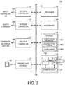
- Fig. 2 is a schematic diagram illustrating an example of the hardware configuration of the standard control unit 100 configuring the control device 2 according to this embodiment.
- the standard control unit 100 includes a processor 102, a main memory 104, a storage 106, network controllers 108 and 110, a field bus controller 112, a memory card interface 116, and a local bus controller 120. Such components are connected through a processor bus 130.
- the processor 102 corresponds to an arithmetic operation processing unit executing a control operation and the like and may be composed of a central processing unit (CPU), a graphics processing unit (GPU), or the like. More specifically, the processor 102 reads programs (a system program 1060 and a standard control program 1062) stored in the storage 106, expands the programs into the main memory 104, and executes the programs, thereby realizing control according to a control target and various processes to be described later.
- programs a system program 1060 and a standard control program 1062
- the main memory 104 is configured by a volatile storage device such as a dynamic random access memory (DRAM) or a static random access memory (SRAM), or the like.
- the storage 106 for example, is configured by a nonvolatile storage device such as a hard disk drive (HDD) or a solid state drive (SSD), or the like.
- the storage 106 except for storing a system program 1060 for realizing a basic function, and, in addition, a standard control program 1062 generated in accordance with a control target such as a facility or a machine is also stored therein. Furthermore, in the storage 106, memory mapping information 1064 used for relaying data transmission, which is performed by the safety control unit 200, using the network controllers 108 and 110 and/or the field bus controller 112 is also stored in the storage 106.
- the network controllers 108 and 110 exchange data frames with other control devices, arbitrary devices, and other arbitrary information processing devices through an arbitrary industrial network.
- Fig. 2 although a configuration having two network controllers 108 and 110 is illustrated, a configuration having a single network controller may be employed.
- the field bus controller 112 exchanges data frames with a remote device through an arbitrary field bus.
- a configuration having a single field bus controller 112 is illustrated, a configuration including a plurality of field bus controllers may be employed.
- the memory card interface 116 is configured such that a memory card 118 that is one example of a recording medium can be detachably attached thereto.
- the memory card interface 116 is configured to be able to write arbitrary data into the memory card 118 and read arbitrary data from the memory card 118.
- the local bus controller 120 exchanges data frames with the safety control unit 200 and an arbitrary safety IO unit 300 through the local bus 10. More specifically, the local bus controller 120 includes a master controller 122, an IO data memory 124, a transmitting circuit (TX) 126, and a receiving circuit (RX) 128.
- TX transmitting circuit
- RX receiving circuit
- the IO data memory 124 is a memory that temporarily stores IO data exchanged with an arbitrary local unit through the local bus 10, and an address is defined in association with each local unit in advance.
- the transmitting circuit 126 generates a communication frame including output data and transmits the generated communication frame to the local bus 10.
- the receiving circuit 128 receives a communication frame transmitted on the local bus 10 and demodulates the communication frame into input data.
- the master controller 122 controls the IO data memory 124, the transmitting circuit 126, and the receiving circuit 128 in accordance with a data transmission timing and the like on the local bus 10.
- the master controller 122 provides control as a communication master managing data transmission on the local bus 10 and the like.
- a dedicated hardware circuit for example, an application specific integrated circuit (ASIC) or a field-programmable gate array (FPGA), or the like.
- major parts of the standard control unit 100 may be realized using hardware according to a general-purpose architecture (for example, an industrial PC based on a general-purpose PC).
- OS operating systems
- a configuration integrating functions of a display device, a supporting device, and the like in the standard control unit 100 may be employed.
- a universal serial bus (USB) port and a USB controller for exchanging data with the supporting device may further be disposed.
- USB universal serial bus
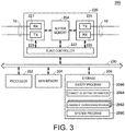
- Fig. 3 is a schematic diagram illustrating an example of the hardware configuration of the safety control unit 200 configuring the control device 2 according to this embodiment.
- the safety control unit 200 includes a processor 202, a main memory 204, a storage 206, and a local bus controller 220. Such components are connected through a processor bus 230.
- the processor 202 corresponds to an arithmetic operation processing unit that executes one or a plurality of safety programs.
- the local bus controller 220 functions as a slave device for communication and provides a communication interface that is similar to another local unit. In other words, the local bus controller 220 exchanges data frames with the standard control unit 100 and a local unit through the local bus 10.
- the safety control unit 200 and the safety IO unit 300 are connected using, for example, a daisy chain connection.
- the local bus controller 220 takes in the communication frame that has arrived.
- the local bus controller 220 when a communication frame addressed to its own unit arrives from a device located on the downstream side on the local bus 10, takes in the communication frame that has arrived.
- the communication frame passes through the local bus controller 220 as it is. In accordance with the reception or the passage of the communication frame, inter-node data transmission among the standard control unit 100, the local unit, and the safety control unit 200 is realized.
- the local bus controller 220 includes a slave controller 222, a buffer memory 224, transmitting circuits (TX) 225 and 226, and receiving circuits (RX) 227 and 228.
- TX transmitting circuits
- RX receiving circuits
- the buffer memory 224 temporarily stores a communication frame transmitted through the local bus 10.
- the receiving circuit 227 When a communication frame transmitted on the local bus 10 is received, the receiving circuit 227 stores the whole or a part thereof in the buffer memory 224. The transmitting circuit 226 transmits the communication frame received by the receiving circuit 227 to the local bus 10 on the downstream side.
- the receiving circuit 228 stores the whole or a part thereof in the buffer memory 224.
- the transmitting circuit 225 transmits the communication frame received by the receiving circuit 128 to the local bus 10 disposed on the downstream side.
- the slave controller 222 controls the transmitting circuits 225 and 226, the receiving circuits 227 and 228, and the buffer memory 224.
- the processor 202 corresponds to an arithmetic operation processing unit that executes a control operation and the like and may be composed of a CPU, a GPU, or the like. More specifically, the processor 202 reads programs (as an example, a system program 2060, a communication processing program 2062, and a safety program 2066) stored in the storage 206, expands the programs into the main memory 204, and executes the programs, thereby realizing control according to a control target and various processes to be described later.
- programs as an example, a system program 2060, a communication processing program 2062, and a safety program 2066
- the main memory 204 is configured by a volatile storage device such as a DRAM or an SRAM or the like.
- the storage 206 for example, is configured by a nonvolatile storage device such as an HDD or an SSD or the like.
- a communication processing program 2062 for establishing and maintaining a connection for exchange of data frames with other safety control unit 200 and/or the safety IO unit 300, connection setting information 2064 including setting information required for establishing and maintaining a connection, and a safety program 2066 generated in accordance with a safety IO unit 300 as the target device are stored.
- a configuration example in which necessary functions are provided by the processor 202 executing programs has been illustrated in Fig. 3
- all or some of the provided functions may be mounted using a dedicated hardware circuit (for example, an ASIC, an FPGA, or the like).
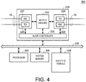
- Fig. 4 is a schematic diagram illustrating an example of the hardware configuration of the safety IO unit 300 configuring the control device 2 according to this embodiment.
- the safety IO unit 300 includes a processor 302, a system memory 306, a safety IO module 308, and a local bus controller 320. Such components are connected through a processor bus 330.
- the local bus controller 320 functions as a slave device for communication and provides a communication interface similar to other local units.
- the local bus controller 320 includes a slave controller 322, a buffer memory 324, transmitting circuits (TX) 325 and 326, and receiving circuits (RX) 327 and 328.
- the basic configuration of the local bus controller 320 is similar to the local bus controller 220 illustrated in Fig. 3 , and thus detailed description thereof will not be repeated here.
- the processor 302 corresponds to an arithmetic operation processing unit executing various processes in the safety IO unit 300.
- the system memory 306 is configured by a flash memory, a non-volatile RAM (NVRAM), or the like and stores various settings and firmware that are necessary for the process performed by the safety IO unit 300.
- the safety IO module 308 performs an input process on a signal supplied from a field and/or an output process of outputting a signal to a field in accordance with the function of the safety IO unit 300.
- functions that are unique to safety control such as detection of formation of a short circuit and feedback detection are further implemented in the safety IO module 308.
- a configuration example in which necessary functions are provided using the processor 302 has been illustrated in Fig. 4
- some or all of the provided functions may be mounted using a dedicated hardware circuit (for example, an ASIC, an FPGA, or the like).
- Fig. 5 is a schematic diagram illustrating an example of the hardware configuration of the communication unit 400 configuring the control device 2 according to this embodiment.
- the communication unit 400 includes a processor 402, a main memory 404, a storage 406, network controllers 408 and 410, a field bus controller 412, and a local bus controller 420. Such components are connected through a processor bus 430.
- the processor 402 corresponds to an arithmetic operation processing unit that executes a control operation and the like and is composed of a CPU, a GPU, and the like. More specifically, the processor 402 reads a system program 4060 stored in the storage 406, expands the program into the main memory 404, and executes the program, thereby realizing various processes for relaying exchange of IO data between a local unit (the safety IO unit 300 or the like) that is connected through the local bus 10 and the standard control unit 100 and/or the safety control unit 200.
- a local unit the safety IO unit 300 or the like
- the main memory 404 is configured by a volatile storage device such as a DRAM or an SRAM or the like.
- the storage 406, for example, is configured by a nonvolatile storage device such as an HDD or an SSD or the like.
- a system program 4060 for realizing a function of the local unit for exchanging IO data is stored.
- the network controllers 408 and 410 exchange data frames with another control device, an arbitrary device, and other arbitrary information processing devices through an arbitrary industrial network. Although a configuration having two network controllers 408 and 410 is illustrated in Fig. 5 , a configuration having a single network controller may be employed.
- the field bus controller 412 exchanges a data frame with a remote device through an arbitrary field bus. Although a configuration having the single field bus controller 412 is illustrated in Fig. 5 , a configuration having a plurality of field bus controllers may be employed.
- the local bus controller 420 exchanges data frames with the safety control unit 200 and an arbitrary safety IO unit 300 through the local bus 10. More specifically, the local bus controller 420 includes a master controller 422, an IO data memory 424, a transmitting circuit (TX) 426, and a receiving circuit (RX) 428.
- TX transmitting circuit
- RX receiving circuit
- the IO data memory 424 is a memory that temporarily stores IO data to be exchanged with an arbitrary local unit through the local bus 10, and an address is defined in advance in association with each local unit.
- the transmitting circuit 426 generates a communication frame including output data and transmits the generated communication frame on the local bus 10.
- the receiving circuit 428 demodulates a communication frame transmitted on the local bus 10 and demodulates the received communication frame into input data.
- the master controller 422 controls the IO data memory 424, the transmitting circuit 426, and the receiving circuit 428 in accordance with a data transmission timing and the like on the local bus 10.
- the mater controller 422 provides control as a communication master that manages data transmission on the local bus 10 and the like.
- a configuration example in which necessary functions are provided by the processor 402 executing programs is illustrated in Fig. 5
- some or all of the provided functions may be mounted using a dedicated hardware circuit (for example, an ASIC, an FPGA, or the like).
- the main configuration of the communication coupler unit 450 is similar to the communication unit 400 except that the type or the number of networks of a connection destination are different from those of the communication unit 400. For this reason, detailed description thereof will not be repeated here.
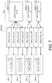
- Figs. 6 and 7 are schematic diagrams illustrating one example of an execution environment of a safety program in the safety control unit 200 of the safety control system 1 according to this embodiment.
- the safety control unit 200 includes four communication processing units 260-1, 260-2, 260-3, and 260-4. It is assumed that the communication processing unit 260-1 has established the first connection 12, the communication processing unit 260-2 has established the second connection 14, the communication processing unit 260-3 has established the third connection 16, and the communication processing unit 260-4 has established the fourth connection 18.
- Each of the communication processing units 260-1 to 260-4 exchanges safety IO data with a safety IO unit 300 as the target device and/or the safety control unit 200 in accordance with each connection setting. In other words, each of the communication processing units 260-1 to 260-4 exchanges safety IO data with a device that is a connection destination.
- a communication period (a transmission/reception period of an FSoE frame or a CIP frame) of each of the communication processing units 260-1 to 260-4 is set on the basis of a setting and a status of each connection.
- the communication period may be changed also in accordance with the magnitude of the amount of exchanged data and the like set in the connection.
- the period may not be a constant period and may be changed in a range not exceeding a worst value set in advance. In this way, the execution periods of exchange of safety input/output data using the communication processing units 260-1 to 260-4 are set as being independent from each other.
- the exchanged safety IO data is stored in the main memory 204 as a safety IO data map 250.
- the main memory 204 storing the safety IO data map 250 corresponds to a data storing unit that stores safety input data to be referred to by one or a plurality of safety programs 2066 and safety output data output by executing one or a plurality of safety programs 2066.
- each of the communication processing units 260-1 to 260-4 periodically transmits safety output data for a target device stored in the safety IO data map 250 (a data storing unit) to the target device independently from the processes of the other communication processing units 260 and writes safety input data from the target device into the safety IO data map 250 (the data storing unit).
- An update range of the safety IO data map 250 is basically independent for each connection.
- the safety program 2066 executed by the safety control unit 200 refers to arbitrary safety input data (Safety Input) on the safety IO data map 250 and writes a result of the arithmetic operation into data corresponding to the safety output data (Safety Output). While the safety program 2066 can use arbitrary safety IO data on the safety IO data map 250, for example, as illustrated in Fig. 6 , the safety program 2066 may be generated for each safety IO data exchanged in each connection.
- the configuration example illustrated in Fig. 6 illustrates an example in which a safety program 2066-1 using only safety IO data exchanged in the first connection 12, a safety program 2066-2 using only safety IO data exchanged in the second connection 14, a safety program 2066-3 using only safety IO data exchanged in the third connection 16, and a safety program 2066-4 using only safety IO data exchanged in the fourth connection 18 are respectively executed.
- Each of the safety programs 2066-1 to 2066-4 may be executed at independent periods.
- a maximum execution period and the like of the safety program may be set, and, in such a case, the safety program is executed at a period according to each request.
- each of the plurality of communication processing units 260-1 to 260-4 associates the safety programs 2066-1 to 2066-4 with each safety IO data exchanged with a target device, and accordingly, even in a case in which a malfunction occurs in a certain connection among a plurality of connections, there is no influence thereof on safety programs relating to the other connections.
- Fig. 7 illustrates an example in which a safety program 2066-12 using both safety IO data exchanged in the first connection 12 and safety IO data exchanged in the second connection 14 is executed.
- a safety program can be generated without user's awareness of a connection in which safety IO data for a target device is exchanged.
- Variables can be assigned in units of values or data to the safety IO data map 250 as illustrated in Figs. 6 and 7 .
- each value of the safety IO data may be designated using such variables.
- the safety program by designating variables assigned to safety IO data stored in the safety IO data map 250 (the data storing unit), may refer to a value of corresponding safety IO data.
- FSoE frames exchanged between the safety control unit 200 and the safety IO unit 300 through the local bus 10 will be described.
- the safety control unit 200 exchanges safety IO data between the standard control unit 100 and the safety IO unit 300 connected to the safety control unit 200 through the local bus 10.
- Fig. 8 is a schematic diagram illustrating realization of exchange of an FSoE frame in the control device 2 of the safety control system 1 according to this embodiment.
- the local bus controller 120 of the standard control unit 100 functions as a communication master of the local bus 10 and is connected to the local bus controller 220 of the safety control unit 200 and the local bus controller 320 of the safety IO unit 300 through the local bus 10 to enable data transmission.
- the safety control unit 200 includes a communication processing unit 260 for establishing a connection with the safety IO unit 300.
- the communication processing unit 260 is realized by the processor 202 of the safety control unit 200 executing the system program 2060.
- the communication processing unit 260 reflects safety IO data transmitted/received by the local bus controller 220 on the safety IO data map 250.
- the communication processing unit 260 updates a corresponding value in the safety IO data map 250 with safety input data received in an FSoE frame from the safety IO unit 300, includes a value output to the safety IO data map 250 in accordance with execution of the safety program 2066 in the FSoE frame as safety output data, and transmits the resultant FSoE frame.
- the safety IO unit 300 includes the safety IO module 308 as well as a communication processing unit 360 for establishing a connection with the safety control unit 200.
- the communication processing unit 360 is realized by the processor 302 of the safety IO unit 300 executing the system program 3060.
- both the safety control unit 200 and the safety IO unit 300 are slave devices for communication, and accordingly, FSoE frames exchanged between two units are transmitted through the standard control unit 100 that is a communication master.
- frames with a predetermined size are periodically transmitted in the local bus 10, and an FSoE frame is transmitted as a message frame during an interval between the periodical transmissions of the frames.
- the FSoE frame transmitted from the safety control unit 200 is transmitted to the standard control unit 100 once and then is transmitted to a safety IO unit 300 as the target device.
- the FSoE frame transmitted from the safety control unit 200 is transmitted to the standard control unit 100 once and then is transmitted to the safety control unit 200.
- a connection is established between the safety control unit 200 and the safety IO unit 300, and safety IO data is exchanged.
- the safety control unit 200 is responsible for generation and decoding of a CIP frame in this embodiment, actual transmission/reception of CIP frames is assigned to the standard control unit 100.
- the communication processing unit 260 disposed in the safety control unit 200 exchanges safety IO data with a device that is a connection destination using the network controllers 108 and 110 that are network interfaces of the standard control unit 100.
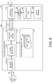
- Fig. 9 is a schematic diagram illustrating realization of exchange of a CIP frame in the control device 2 of the safety control system 1 according to this embodiment.
- the safety control unit 200 includes a communication processing unit 260 used for establishing a connection with another unit.
- the communication processing unit 262 is realized by the processor 202 of the safety control unit 200 executing the system program 2060.
- the communication processing unit 262 In a case in which a CIP frame addressed to a target unit is to be transmitted, the communication processing unit 262 generates the CIP frame to be transmitted and transmits the generated CIP frame to the local bus controller 120 of the standard control unit 100 using a data frame that is periodically transmitted on the local bus 10. In addition, the communication processing unit 262 receives a CIP frame that is transmitted using a data frame periodically transmitted on the local bus 10 from any unit. This CIP frame is received by the network controllers 108 and 110 of the standard control unit 100 and is transmitted to the safety control unit 200 through the local bus 10 via the local bus controller 120.
- the communication processing unit 262 reflects the safety IO data exchanged using the CIP frame on the safety IO data map 250.
- the communication processing unit 262 updates a corresponding value in the safety IO data map 250 with the safety input data received using the CIP frame from one unit, includes a value output to the safety IO data map 250 in accordance with execution of the safety program 2066 in the CIP frame as safety output data, and transmits the resultant CIP frame.
- the standard control unit 100 includes a connection managing unit 160 connected to the local bus controller 120.
- the local bus controller 120 includes a local bus-side buffer 1242 and a network-side buffer 1244.
- the network-side buffer 1244 corresponds to a buffer for a CIP frame that is transmitted/received by the network controllers 108 and 110. More specifically, in a case in which CIP frames are to be transmitted to a target unit, the connection managing unit 160 moves the CIP frames for transmission stored in the local bus-side buffer 1242 to the network-side buffer 1244 at appropriate timings with an appropriate order. On the other hand, in a case in which the network controllers 108 and 110 receive a CIP frame from one unit, the connection managing unit 160 moves CIP frames for transmission stored in the network-side buffer 1244 to the local bus-side buffer 1242 at appropriate timing in an appropriate order.
- connection managing unit 160 realizes exchange of the CIP frames between the safety control unit 200 and one unit connected through a network.
- the connection managing unit 160 includes connection management information 162 and manages routing to a unit, which is a communication destination for each connection, set for the safety control unit 200 and the like.
- the safety control unit 200 adds connection identification information used for identifying each connection to a data frame, and the connection managing unit 160 identifies a destination to which a CIP frame transmitted from the safety control unit 200 is transmitted by referring to the connection identification information.
- the safety control unit 200 can establish an arbitrary connection with an arbitrary unit on a network through the local bus 10.
- Transmission of an FSoE frame on the network is realized using exchange of a data frame between the safety control unit 200 and the standard control unit 100 through the local bus 10 in a form similar to that of the transmission of a CIP frame on the network.
- a data frame between the safety control unit 200 and the standard control unit 100 through the local bus 10 in a form similar to that of the transmission of a CIP frame on the network.
- the safety control unit 200 can establish one or a plurality of connections.
- the connections can be independent from each other, and, even in a case in which a certain malfunction occurs in one connection, there is no influence thereof on the other connections.
- a timing for data update between the local bus-side buffer 1242 and the network-side buffer 1244 in the local bus controller 120 may be optimized.
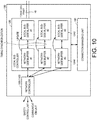
- Fig. 10 is a schematic diagram illustrating one example of a data update in the local bus controller 120 of the standard control unit 100 of the safety control system 1 according to this embodiment.
- a local bus-side buffer 1242 and a network-side buffer 1244 are prepared for each connection.
- the connection managing unit 160 controls a timing for data update for a set of the local bus-side buffer 1242 and the network-side buffer 1244, and accordingly, safety IO data for each connection can be updated for the safety control unit 200 at substantially same timings.
- connection managing unit 160 simultaneously executes a data update for each set formed by the local bus-side buffer 1242 and the network-side buffer 1244 on the basis of a status and the like of exchange of a data frame in each connection.
- the connection managing unit 160 simultaneously executes a data update for each set formed by the local bus-side buffer 1242 and the network-side buffer 1244 on the basis of a status and the like of exchange of a data frame in each connection.
- timings of reflection of safety input data on the safety control unit 200 can be configured to coincide with each other.
- transmission timings of safety output data output from the safety control unit 200 to units can be configured to coincide with each other.
- control device 2 in which the standard control unit 100 and the safety control unit 200 are combined has been illustrated, the disclosure is not limited thereto. Thus, it is apparent that the technical idea of the disclosure can be applied also to a control device in which a plurality of standard control units 100 are combined and a control device in which a plurality of safety control units 200 are combined. In addition, the disclosure is not limited to the standard control unit and the safety control unit, and a combination of arbitrary control units may be employed.
- This embodiment as described above includes a technical idea as described below.
- a safety control system (1) realizing functional safety including: an arithmetic operation processing unit (202) that executes one or a plurality of safety programs (2066); a data storing unit (204; 250) that stores safety input data referred to by the one or plurality of safety programs and safety output data output in accordance with execution of the one or plurality of safety programs; and a plurality of communication processing units (2062; 260) that exchange safety input/output data with a device that is a connection destination, wherein each of the plurality of communication processing units, independently from processes of the other communication processing units, periodically transmits safety output data for a target device stored in the data storing unit to the target device and writes safety input data from the target device into the data storing unit in accordance with a connection setting (2064) set in advance for each of the communication processing units.
- the standard control unit includes a network interface 108; 110), and the communication processing unit disposed in the safety control unit exchanges safety input/output data with a device that is a connection destination using the network interface of the standard control unit.
- a safety control unit (200) realizing functional safety including: an arithmetic operation processing unit (202) that executes one or a plurality of safety programs (2066); a data storing unit (204; 250) that stores safety input data referred to by the one or plurality of safety programs and safety output data output in accordance with execution of the one or plurality of safety programs; and a plurality of communication processing units (2062; 260) that exchange safety input/output data with a device that is a connection destination, wherein each of the plurality of communication processing units, independently from processes of the other communication processing units, periodically transmits safety output data for a target device stored in the data storing unit to the target device and writes safety input data from the target device into the data storing unit in accordance with a connection setting (2064) set in advance for each of the communication processing units.
- a system realizing safety control for realizing functional safety is requested to have a high degree of reliability.
- a safety controller having a high level of reliability is relatively highly priced, and, by disposing a plurality of safety controllers, a hardware cost may increase.
- a design cost and a maintenance cost may increase.
- a plurality of connections can be established using a single safety control unit, and, even in a case in which a malfunction occurs in one connection, there is no substantial influence on the other connections, and safety control can be continued.
Landscapes
- Engineering & Computer Science (AREA)
- Physics & Mathematics (AREA)
- General Physics & Mathematics (AREA)
- Automation & Control Theory (AREA)
- Human Computer Interaction (AREA)
- Manufacturing & Machinery (AREA)
- Programmable Controllers (AREA)
- Small-Scale Networks (AREA)
Abstract
Description
- The disclosure relates to a safety control system and a safety control unit realizing functional safety.
- In order to safely use facilities and machines used at various manufacturing sites, it is necessary to realize functional safety in accordance with international standards such as International Electrotechnical Commission (IEC) 61508. Such functional safety may be realized by a safety control device executing a safety program. For example, Japanese Laid-open Publication No.
2005-031778 - As one method for realizing comprehensive functional safety for facilities, machines, and the like present at a manufacturing site, in a configuration in which various safety components are connected to the safety control device as described above, safety control is executed for a safety input signal input from each safety component, and a safety output signal is given to each safety component on the basis of a result of the control is preferable.
- Meanwhile, connection forms and communication protocols for connecting the safety control device to the safety components are not necessarily uniform, and thus there are a plurality of forms and protocols. For example, when a communication protocol that can be used by a safety control device that has been newly introduced and a communication protocol that can be used by an existing safety component do not coincide with each other, it is necessary to employ a configuration in which a wiring is laid between the safety component and the safety control device, and an electric signal is directly exchanged therebetween.
- An objective of the disclosure is to solve the problems described above, and the disclosure provides a safety control system capable of realizing comprehensive safety control for a manufacturing site.
- According to one example of the disclosure, a safety control system realizing functional safety is provided. The safety control system includes: an arithmetic operation processing unit that executes one or a plurality of safety programs, a data storing unit that stores safety input data referred to by the one or plurality of safety programs and safety outputs data output in accordance with execution of the one or plurality of safety programs, and a plurality of communication processing units that exchange safety input/output data with a device that is a connection destination. Each of the plurality of communication processing units, independently from processes of the other communication processing units, periodically transmits safety output data for a target device stored in the data storing unit to the target device and writes safety input data from the target device into the data storing unit in accordance with a connection setting set in advance for each of the communication processing units.
- According to this disclosure, by performing a connection setting unique for each of the plurality of communication processing units, safety input/output data can be exchanged with a plurality of devices, and, accordingly, a plurality of functional safeties associated with respective device can be realized.
- In the disclosure described above, a safety program may be associated with each piece of safety input/output data exchanged by each of the plurality of communication processing units with the target device. According to this disclosure, even in a case in which an abnormality occurs in one connection (communication processing unit), the abnormality has no influence on execution of safety programs associated with the other connections.
- In the disclosure described above, execution periods of exchange of the safety input/output data executed by the plurality of communication processing units may be independent from each other. According to this disclosure, the safety input/output data can be exchanged at a period according to a setting or a status of each connection.
- In the disclosure described above, the one or plurality of safety programs may refer to values of corresponding safety input/output data by designating variables assigned to the safety input/output data stored in the data storing unit. According to this disclosure, a person generating a safety program can generate the safety program without being aware of a connection (communication processing unit) responsible for update of each safety input/output data.
- In the disclosure described above, the safety control system may be formed of a standard control unit that mainly executes standard control and a safety control unit that mainly executes safety control, wherein the arithmetic operation processing unit, the data storing unit, and the communication processing units may be disposed in the safety control unit. According to this disclosure, safety control can be executed separately from standard control, and the reliability of the safety control can be improved.
- In the disclosure described above, the standard control unit and the safety control unit are connected through a local bus, the standard control unit includes a network interface, and the communication processing unit disposed in the safety control unit may exchange safety input/output data with a device that is a connection destination using the network interface of the standard control unit. According to this disclosure, a network interface does not need to be disposed in the safety control unit, and, accordingly, the configuration can be simplified.
- In the disclosure described above, at least one communication processing unit among the plurality of communication processing units may exchange safety input/output data with the standard control unit and a safety input/output (IO) unit connected to the safety control unit through the local bus. According to this disclosure, safety control can be realized using the safety input/output data managed by the safety IO unit connected to a common local bus.
- In the disclosure described above, at least one among the plurality of communication processing units may exchange safety input/output data with a device on a network in accordance with an Ethernet (registered trademark)-based communication protocol. According to this disclosure, safety control can be realized while using Ethernet that is a general-purpose communication protocol.
- According to one example of this disclosure, a safety control unit realizing functional safety is provided. The safety control unit includes: an arithmetic operation processing unit that executes one or a plurality of safety programs, a data storing unit that stores safety input data referred to by the one or plurality of safety programs and safety output data output in accordance with execution of the one or plurality of safety programs, and a plurality of communication processing units that exchange safety input/output data with a device that is a connection destination. Each of the plurality of communication processing units, independently from processes of the other communication processing units, periodically transmits safety output data for a target device stored in the data storing unit to the target device and writes safety input data from the target device into the data storing unit in accordance with a connection setting set in advance for each of the communication processing units.
- According to the disclosure, comprehensive safety control for a manufacturing site can be realized.
-
-
Fig. 1 is a schematic diagram illustrating an example of the configuration of a safety control system according to this embodiment; -
Fig. 2 is a schematic diagram illustrating an example of the hardware configuration of a standard control unit configuring a control device according to this embodiment; -
Fig. 3 is a schematic diagram illustrating an example of the hardware configuration of a safety control unit configuring the control device according to this embodiment; -
Fig. 4 is a schematic diagram illustrating an example of the hardware configuration of a safety IO unit configuring the control device according to this embodiment; -
Fig. 5 is a schematic diagram illustrating an example of the hardware configuration of a communication unit configuring the control device according to this embodiment; -
Fig. 6 is a schematic diagram illustrating one example of an execution environment of a safety program in the safety control unit of the safety control system according to this embodiment; -
Fig. 7 is a schematic diagram illustrating one example of an execution environment of a safety program in the safety control unit of the safety control system according to this embodiment; -
Fig. 8 is a schematic diagram illustrating realization of exchange of a Safety over Ethernet for Control Automation Technology (EtherCAT) (FSoE) frame in the control device of the safety control system according to this embodiment; -
Fig. 9 is a schematic diagram illustrating realization of exchange of a common industrial protocol (CIP) frame in the control device of the safety control system according to this embodiment; and -
Fig. 10 is a schematic diagram illustrating one example of a data update in a local bus controller of the standard control unit of the safety control system according to this embodiment. - An embodiment of the disclosure will be described in detail with reference to the drawings. The same reference sign will be assigned to the same parts or parts corresponding to each other in the drawings, and description thereof will not be repeated.
- First, one example of a view to which the disclosure is applied will be described.
Fig. 1 is a schematic diagram illustrating an example of the configuration of asafety control system 1 according to this embodiment. Thesafety control system 1 is a system for realizing functional safety. - In
Fig. 1 , thesafety control system 1 having acontrol device 2 and acontrol device 4 as its major components is illustrated as one example. In thesafety control system 1, thecontrol device 2 is connected to a wiring LN1 that is a backbone wiring through a wiring LN2, and thecontrol device 4 is connected to the wiring LN1 through a wiring LN3. - Each of the
control device 2 and thecontrol device 4 may be configured to execute standard control and safety control. - In description here, the term "standard control" typically collectively refers to processes for controlling a control target in accordance with required specifications set in advance. On the other hand, the "safety control" collectively refers to processes for preventing persons from being endangered by a certain facility, a certain machine, or the like due to a certain malfunction. The safety control, for example, realizes functional safety defined in International Electrotechnical Commission (IEC) 61508 or the like. More specifically, the safety control includes a process that stops a control target not only in a case in which a behavior of the control target is different from the original behavior but also in a case in which it is determined that a certain abnormality has occurred in the
control device 2. - Although both the standard control and the safety control may be realized by the same unit, in the
safety control system 1, a configuration example is illustrated in which astandard control unit 100 mainly responsible for the standard control and asafety control unit 200 mainly responsible for the safety control are used. - In other words, each of the
control device 2 and thecontrol device 4 is composed of astandard control unit 100 and asafety control unit 200. Thesafety control unit 200 serving as one type of local unit is connected to thestandard control unit 100 through alocal bus 10. - In description here, a "local unit" collectively refers to an arbitrary unit connected through the
local bus 10. - Each of the
control device 2 and thecontrol device 4 additionally includes one or a plurality ofsafety IO units 300. Thesafety IO unit 300 manages an input of a signal from a safety component and/or an output of a signal to a safety component. In the disclosure herein, the "safety component" mainly includes arbitrary devices used for the safety control and, for example, includes a safety relay, various safety sensors, and the like. - The
safety control unit 200 exchanges safety IO data with one or a plurality ofsafety IO units 300 through thelocal bus 10. In description here, the term "IO data" includes input data acquired from a control target or a safety component and/or output data output to a control device or a safety component. In the "IO data", particularly, safety input/output data used for the safety control will be referred to as "safety IO data". - The
control device 2 is additionally connected to aremote IO device 3 through a wiring LN6, and thecontrol device 4 is additionally connected to aremote IO device 5 through a wiring LN7. Generally, theremote IO device 3 and theremote IO device 5 are disposed at positions different from those of thecontrol device 2 and thecontrol device 4, exchange signals with a control target or a safety component, and exchange IO data corresponding to the exchange of signals with thestandard control unit 100. - More specifically, each of the
remote IO device 3 and theremote IO device 5 is composed of acommunication coupler unit 450 and one or a plurality ofsafety IO units 300. Asafety IO unit 300 as one type of local unit is connected to thecommunication coupler unit 450 through a local bus (not illustrated in the drawing). - The
safety control system 1 additionally includes aremote IO device 6, a remote IO device 7, and a remote IO device 8. Theremote IO device 6 is connected to the wiring LN1 through a wiring LN4. The remote IO device 7 is connected to theremote IO device 6 through a wiring LN8. The remote IO device 8 is connected to the remote IO device 7 through a wiring LN9. - Each of the
remote IO device 6, the remote IO device 7, and the remote IO device 8 is composed of acommunication unit 400 and one or a plurality ofsafety IO units 300. Thesafety IO unit 300 as one type of local unit is connected to thecommunication unit 400 through a local bus (not illustrated in the drawing). The basic function and the basic configuration of thecommunication unit 400 are similar to those of thecommunication coupler unit 450. - In addition, the
control device 2 is also connected to arobot 500 including a safety component through a wiring LN5 using a network. - In the
safety control system 1 according to this embodiment, thesafety control unit 200 can establish one or a plurality of connections, which are independent from each other, with another control unit and/or thecommunication unit 400. In each connection, safety IO data can be exchanged at every period set in advance. - For example, when focusing on the
safety control unit 200 of thecontrol device 2, (1) afirst connection 12 established with one or a plurality ofsafety IO units 300 connected through thelocal bus 10 of thecontrol device 2, (2) asecond connection 14 established between thecontrol device 2 and theremote IO device 3 connected through the wiring LN6, (3) athird connection 16 established between thecontrol device 2 and therobot 500 connected through the wiring LN5, (4) afourth connection 18 established between thecontrol device 2 and thesafety control unit 200 of thecontrol device 4 connected through the wirings LN2, LN1, and LN3 are managed. - In the
local bus 10, data transmission according to a communication protocol that is specific to a manufacturer of thecontrol device 2 or data transmission according to a standardized communication protocol such as Ethernet for Control Automation Technology (a registered trademark) is performed. For example, in a case in which transmission of a form in which process data is sequentially transmitted at a predetermined period is employed as a manufacturer-specific communication protocol, by inserting a message frame called a Safety over EtherCAT (FSoE) into the process data, exchange of safety IO data between connections can be realized. On the other hand, in a case in which data transmission according to EtherCAT is employed, by inserting an FSoE frame (message frame) into process data that is sequentially transmitted in accordance with EtherCAT, exchange of safety IO data between connections can be realized. - In this way, in a case in which the
first connection 12 is established between thesafety control unit 200 and a specificsafety IO unit 300 through thelocal bus 10, a target unit with which an FSoE frame is to be exchanged, a data size thereof, and the like are defined in advance. - Also, in the wiring LN6 between the
control device 2 and theremote IO device 3, data transmission according to a standardized communication protocol, such as EtherCAT, is performed. Also, between thesafety control unit 200 of thecontrol device 2 and one or the plurality ofsafety IO units 300 of theremote IO device 3, exchange of safety IO data is realized using an FSoE frame. - EtherCAT is an Ethernet-based communication protocol, and Ethernet (a registered trademark) is employed in a physical layer and a data link layer (network interface layer) of EtherCAT, and, accordingly, a medium that can transmit packets such as a local area network (LAN) cable is used for the wiring LN6.
- In this way, in a case in which the
second connection 14 is established between thesafety control unit 200 and a specificsafety IO unit 300 through the wiring LN6, a target unit with which an FSoE frame is exchanged, a data size thereof, and the like are defined in advance. - Here, in the
control device 2, a network interface responsible for data transmission according to EtherCAT (afield bus controller 112 illustrated inFig. 2 ) is mounted in thestandard control unit 100. For this reason, in thecontrol device 2, thestandard control unit 100 directly exchanges an FSoE frame with asafety IO unit 300 as the target device, and thesafety control unit 200 receives an FSoE frame from thesafety IO unit 300 using a data frame on thelocal bus 10 that is periodically exchanged with thestandard control unit 100 as a relay medium and transmits the FSoE frame to thesafety IO unit 300. Details of the process using a data frame on thelocal bus 10 as a relay medium will be described later. - In the wiring LN5 between the
control device 2 and therobot 500, data transmission according to an industrial communication protocol is performed. As such industrial communication protocols, there are EtherNet/Internet protocol (IP), DeviceNet, CompoNet, ControlNet, and the like. In this embodiment, as a typical example, it is assumed that data transmission according to EtherNet/IP is employed. By using such a communication protocol of data transmission, a communication protocol such as a common industrial protocol (CIP) or CIP safety is mounted as an application layer. - As a typical example, between the
safety control unit 200 of thecontrol device 2 and therobot 500, a configuration in which safety IO data is exchanged in accordance with CIP Safety mounted using an EtherNet/IP is illustrated. The EtheNet/IP is an Ethernet-based communication protocol. CIP Safety is a communication protocol associated with functional safety standards such as IEC 61508 using the CIP as a base. - In this way, in a case in which the
third connection 16 is established between thesafety control unit 200 and therobot 500 through the wiring LN5, a data size for exchanging a data frame according to CIP Safety (hereinafter, abbreviated to a "CIP frame"), a tag name designating a target variable, and the like are defined in advance. - Here, in the
control device 2, a network interface responsible for data transmission according to the EtherNet/IP (anetwork controller 110 illustrated inFig. 2 ) is mounted in thestandard control unit 100. For this reason, in thecontrol device 2, thestandard control unit 100 directly exchanges a CIP frame according to CIP Safety with atarget robot 500, and thesafety control unit 200 receives a CIP frame from therobot 500 using a data frame on thelocal bus 10 that is periodically exchanged with thestandard control unit 100 as a relay medium and transmits the CIP frame to therobot 500. Details of the process using a data frame on thelocal bus 10 as a relay medium will be described later. - In the wirings LN2, LN1, and LN3 between the
control device 2 and thecontrol device 4, data transmission according to an industrial communication protocol is performed. As described above, as industrial communication protocols, there are EtherNet/IP, DeviceNet, CompoNet, ControlNet, and the like. In this embodiment, as a typical example, it is assumed that data transmission according to the EtherNet/IP is employed. In addition, between thesafety control unit 200 of thecontrol device 2 and thesafety control unit 200 of thecontrol device 4, safety IO data is exchanged in accordance with the CIP Safety mounted using the EtherNet/IP. - In this way, in a case in which the
fourth connection 18 is established between thesafety control unit 200 of thecontrol device 2 and thesafety control unit 200 of thecontrol device 4 through the wirings LN2, LN1, and LN3, data size for exchange of a data frame according to the CIP Safety (hereinafter, abbreviated to a "CIP frame"), a tag name designating a target variable, and the like are defined in advance. - Here, in the
control device 2, a network interface responsible for data transmission according to the EtherNet/IP (anetwork controller 108 illustrated inFig. 2 ) is mounted in thestandard control unit 100. For this reason, in thecontrol device 2, thestandard control unit 100 directly exchanges a CIP frame according to the CIP Safety with thesafety control unit 200 as the target device, and, by using a data frame on thelocal bus 10 periodically exchanged with thestandard control unit 100 as a relay medium, thesafety control unit 200 receives a CIP frame from thesafety control unit 200 of thecontrol device 4 and transmits the CIP frame to thesafety control unit 200 of thecontrol device 4. Details of the process using a data frame on thelocal bus 10 as a relay medium will be described later. In addition, also, between thestandard control unit 100 and thesafety control unit 200 of thecontrol device 4, similar to the case of between thestandard control unit 100 and thesafety control unit 200 of thecontrol device 2, a connection is established using a data frame on thelocal bus 10 as a relay medium. - As described above, in the
safety control system 1 according to this embodiment, thesafety control unit 200 of thecontrol device 2 maintains a plurality of connections that are independent from each other, and both of safety control that is independent for each connection and/or safety control that associates a plurality of connections with each other can be realized using safety IO data exchanged using each connection. - As used herein, a "device" includes an arbitrary device or an arbitrary unit that can exchange safety IO data.
- Next, an example of the hardware configuration of major devices configuring the
safety control system 1 according to this embodiment will be described. -
Fig. 2 is a schematic diagram illustrating an example of the hardware configuration of thestandard control unit 100 configuring thecontrol device 2 according to this embodiment. As illustrated inFig. 2 , thestandard control unit 100 includes aprocessor 102, amain memory 104, astorage 106,network controllers field bus controller 112, amemory card interface 116, and alocal bus controller 120. Such components are connected through aprocessor bus 130. - The
processor 102 corresponds to an arithmetic operation processing unit executing a control operation and the like and may be composed of a central processing unit (CPU), a graphics processing unit (GPU), or the like. More specifically, theprocessor 102 reads programs (asystem program 1060 and a standard control program 1062) stored in thestorage 106, expands the programs into themain memory 104, and executes the programs, thereby realizing control according to a control target and various processes to be described later. - The
main memory 104 is configured by a volatile storage device such as a dynamic random access memory (DRAM) or a static random access memory (SRAM), or the like. Thestorage 106, for example, is configured by a nonvolatile storage device such as a hard disk drive (HDD) or a solid state drive (SSD), or the like. - In the
storage 106, except for storing asystem program 1060 for realizing a basic function, and, in addition, astandard control program 1062 generated in accordance with a control target such as a facility or a machine is also stored therein. Furthermore, in thestorage 106,memory mapping information 1064 used for relaying data transmission, which is performed by thesafety control unit 200, using thenetwork controllers field bus controller 112 is also stored in thestorage 106. - The
network controllers Fig. 2 , although a configuration having twonetwork controllers - The
field bus controller 112 exchanges data frames with a remote device through an arbitrary field bus. InFig. 2 , although a configuration having a singlefield bus controller 112 is illustrated, a configuration including a plurality of field bus controllers may be employed. - The
memory card interface 116 is configured such that amemory card 118 that is one example of a recording medium can be detachably attached thereto. Thememory card interface 116 is configured to be able to write arbitrary data into thememory card 118 and read arbitrary data from thememory card 118. - The
local bus controller 120 exchanges data frames with thesafety control unit 200 and an arbitrarysafety IO unit 300 through thelocal bus 10. More specifically, thelocal bus controller 120 includes amaster controller 122, anIO data memory 124, a transmitting circuit (TX) 126, and a receiving circuit (RX) 128. - The
IO data memory 124 is a memory that temporarily stores IO data exchanged with an arbitrary local unit through thelocal bus 10, and an address is defined in association with each local unit in advance. The transmittingcircuit 126 generates a communication frame including output data and transmits the generated communication frame to thelocal bus 10. The receivingcircuit 128 receives a communication frame transmitted on thelocal bus 10 and demodulates the communication frame into input data. Themaster controller 122 controls theIO data memory 124, the transmittingcircuit 126, and the receivingcircuit 128 in accordance with a data transmission timing and the like on thelocal bus 10. Themaster controller 122 provides control as a communication master managing data transmission on thelocal bus 10 and the like. - Although a configuration example in which necessary functions are provided by the
processor 102 executing programs has been illustrated inFig. 2 , some or all of the provided functions may be mounted using a dedicated hardware circuit (for example, an application specific integrated circuit (ASIC) or a field-programmable gate array (FPGA), or the like). Alternatively, major parts of thestandard control unit 100 may be realized using hardware according to a general-purpose architecture (for example, an industrial PC based on a general-purpose PC). In such a case, a plurality of operating systems (OS) having different purposes may be executed in a parallel manner using a virtualization technology, and a necessary application may be executed on each OS. In addition, a configuration integrating functions of a display device, a supporting device, and the like in thestandard control unit 100 may be employed. - For example, in a case in which a supporting device is directly connected to the
standard control unit 100, a universal serial bus (USB) port and a USB controller for exchanging data with the supporting device may further be disposed. -
Fig. 3 is a schematic diagram illustrating an example of the hardware configuration of thesafety control unit 200 configuring thecontrol device 2 according to this embodiment. As illustrated inFig. 3 , thesafety control unit 200 includes aprocessor 202, amain memory 204, astorage 206, and alocal bus controller 220. Such components are connected through aprocessor bus 230. - The
processor 202 corresponds to an arithmetic operation processing unit that executes one or a plurality of safety programs. - The
local bus controller 220 functions as a slave device for communication and provides a communication interface that is similar to another local unit. In other words, thelocal bus controller 220 exchanges data frames with thestandard control unit 100 and a local unit through thelocal bus 10. - On the
local bus 10, thesafety control unit 200 and thesafety IO unit 300 are connected using, for example, a daisy chain connection. When a communication frame addressed to its own unit arrives from a device located on the upstream side on thelocal bus 10, thelocal bus controller 220 takes in the communication frame that has arrived. Similarly, thelocal bus controller 220, when a communication frame addressed to its own unit arrives from a device located on the downstream side on thelocal bus 10, takes in the communication frame that has arrived. In a case in which a communication frame not addressed to its own unit has arrived, the communication frame passes through thelocal bus controller 220 as it is. In accordance with the reception or the passage of the communication frame, inter-node data transmission among thestandard control unit 100, the local unit, and thesafety control unit 200 is realized. - More specifically, the
local bus controller 220 includes aslave controller 222, abuffer memory 224, transmitting circuits (TX) 225 and 226, and receiving circuits (RX) 227 and 228. - The
buffer memory 224 temporarily stores a communication frame transmitted through thelocal bus 10. - When a communication frame transmitted on the
local bus 10 is received, the receivingcircuit 227 stores the whole or a part thereof in thebuffer memory 224. The transmittingcircuit 226 transmits the communication frame received by the receivingcircuit 227 to thelocal bus 10 on the downstream side. - Similarly, when a communication frame transmitted on the
local bus 10 is received, the receivingcircuit 228 stores the whole or a part thereof in thebuffer memory 224. The transmittingcircuit 225 transmits the communication frame received by the receivingcircuit 128 to thelocal bus 10 disposed on the downstream side. - In order to realize sequential transmission of communication frames on the
local bus 10, theslave controller 222 controls the transmittingcircuits circuits buffer memory 224. - The
processor 202 corresponds to an arithmetic operation processing unit that executes a control operation and the like and may be composed of a CPU, a GPU, or the like. More specifically, theprocessor 202 reads programs (as an example, asystem program 2060, acommunication processing program 2062, and a safety program 2066) stored in thestorage 206, expands the programs into themain memory 204, and executes the programs, thereby realizing control according to a control target and various processes to be described later. - The
main memory 204 is configured by a volatile storage device such as a DRAM or an SRAM or the like. Thestorage 206, for example, is configured by a nonvolatile storage device such as an HDD or an SSD or the like. - In the
storage 206, in addition to asystem program 2060 for realizing a basic function, acommunication processing program 2062 for establishing and maintaining a connection for exchange of data frames with othersafety control unit 200 and/or thesafety IO unit 300,connection setting information 2064 including setting information required for establishing and maintaining a connection, and asafety program 2066 generated in accordance with asafety IO unit 300 as the target device are stored. - Although a configuration example in which necessary functions are provided by the
processor 202 executing programs has been illustrated inFig. 3 , all or some of the provided functions may be mounted using a dedicated hardware circuit (for example, an ASIC, an FPGA, or the like). -
Fig. 4 is a schematic diagram illustrating an example of the hardware configuration of thesafety IO unit 300 configuring thecontrol device 2 according to this embodiment. As illustrated inFig. 4 , thesafety IO unit 300 includes aprocessor 302, asystem memory 306, asafety IO module 308, and alocal bus controller 320. Such components are connected through aprocessor bus 330. - The
local bus controller 320 functions as a slave device for communication and provides a communication interface similar to other local units. Thelocal bus controller 320 includes aslave controller 322, abuffer memory 324, transmitting circuits (TX) 325 and 326, and receiving circuits (RX) 327 and 328. The basic configuration of thelocal bus controller 320 is similar to thelocal bus controller 220 illustrated inFig. 3 , and thus detailed description thereof will not be repeated here. - The
processor 302 corresponds to an arithmetic operation processing unit executing various processes in thesafety IO unit 300. Thesystem memory 306 is configured by a flash memory, a non-volatile RAM (NVRAM), or the like and stores various settings and firmware that are necessary for the process performed by thesafety IO unit 300. - The
safety IO module 308 performs an input process on a signal supplied from a field and/or an output process of outputting a signal to a field in accordance with the function of thesafety IO unit 300. In addition, functions that are unique to safety control such as detection of formation of a short circuit and feedback detection are further implemented in thesafety IO module 308. - Although a configuration example in which necessary functions are provided using the
processor 302 has been illustrated inFig. 4 , some or all of the provided functions may be mounted using a dedicated hardware circuit (for example, an ASIC, an FPGA, or the like). -
Fig. 5 is a schematic diagram illustrating an example of the hardware configuration of thecommunication unit 400 configuring thecontrol device 2 according to this embodiment. As illustrated inFig. 5 , thecommunication unit 400 includes aprocessor 402, a main memory 404, astorage 406,network controllers field bus controller 412, and alocal bus controller 420. Such components are connected through aprocessor bus 430. - The
processor 402 corresponds to an arithmetic operation processing unit that executes a control operation and the like and is composed of a CPU, a GPU, and the like. More specifically, theprocessor 402 reads asystem program 4060 stored in thestorage 406, expands the program into the main memory 404, and executes the program, thereby realizing various processes for relaying exchange of IO data between a local unit (thesafety IO unit 300 or the like) that is connected through thelocal bus 10 and thestandard control unit 100 and/or thesafety control unit 200. - The main memory 404 is configured by a volatile storage device such as a DRAM or an SRAM or the like. The
storage 406, for example, is configured by a nonvolatile storage device such as an HDD or an SSD or the like. - In the
storage 406, asystem program 4060 for realizing a function of the local unit for exchanging IO data is stored. - The
network controllers network controllers Fig. 5 , a configuration having a single network controller may be employed. - The
field bus controller 412 exchanges a data frame with a remote device through an arbitrary field bus. Although a configuration having the singlefield bus controller 412 is illustrated inFig. 5 , a configuration having a plurality of field bus controllers may be employed. - The
local bus controller 420 exchanges data frames with thesafety control unit 200 and an arbitrarysafety IO unit 300 through thelocal bus 10. More specifically, thelocal bus controller 420 includes amaster controller 422, anIO data memory 424, a transmitting circuit (TX) 426, and a receiving circuit (RX) 428. - The
IO data memory 424 is a memory that temporarily stores IO data to be exchanged with an arbitrary local unit through thelocal bus 10, and an address is defined in advance in association with each local unit. The transmittingcircuit 426 generates a communication frame including output data and transmits the generated communication frame on thelocal bus 10. The receivingcircuit 428 demodulates a communication frame transmitted on thelocal bus 10 and demodulates the received communication frame into input data. Themaster controller 422 controls theIO data memory 424, the transmittingcircuit 426, and the receivingcircuit 428 in accordance with a data transmission timing and the like on thelocal bus 10. Themater controller 422 provides control as a communication master that manages data transmission on thelocal bus 10 and the like. - Although a configuration example in which necessary functions are provided by the
processor 402 executing programs is illustrated inFig. 5 , some or all of the provided functions may be mounted using a dedicated hardware circuit (for example, an ASIC, an FPGA, or the like). - The main configuration of the
communication coupler unit 450 is similar to thecommunication unit 400 except that the type or the number of networks of a connection destination are different from those of thecommunication unit 400. For this reason, detailed description thereof will not be repeated here. - Next, one example of the safety program executed by the
safety control unit 200 of thecontrol device 2 will be described. -
Figs. 6 and7 are schematic diagrams illustrating one example of an execution environment of a safety program in thesafety control unit 200 of thesafety control system 1 according to this embodiment. As illustrated inFigs. 6 and7 , thesafety control unit 200 includes four communication processing units 260-1, 260-2, 260-3, and 260-4. It is assumed that the communication processing unit 260-1 has established thefirst connection 12, the communication processing unit 260-2 has established thesecond connection 14, the communication processing unit 260-3 has established thethird connection 16, and the communication processing unit 260-4 has established thefourth connection 18. - Each of the communication processing units 260-1 to 260-4 exchanges safety IO data with a
safety IO unit 300 as the target device and/or thesafety control unit 200 in accordance with each connection setting. In other words, each of the communication processing units 260-1 to 260-4 exchanges safety IO data with a device that is a connection destination. - A communication period (a transmission/reception period of an FSoE frame or a CIP frame) of each of the communication processing units 260-1 to 260-4 is set on the basis of a setting and a status of each connection. For example, the communication period may be changed also in accordance with the magnitude of the amount of exchanged data and the like set in the connection. In addition, depending on a communication status and the like, the period may not be a constant period and may be changed in a range not exceeding a worst value set in advance. In this way, the execution periods of exchange of safety input/output data using the communication processing units 260-1 to 260-4 are set as being independent from each other.
- The exchanged safety IO data is stored in the
main memory 204 as a safety IO data map 250. Themain memory 204 storing the safety IO data map 250 corresponds to a data storing unit that stores safety input data to be referred to by one or a plurality ofsafety programs 2066 and safety output data output by executing one or a plurality ofsafety programs 2066. - In this way, in accordance with a connection setting set in advance for each
communication processing unit 260, each of the communication processing units 260-1 to 260-4 periodically transmits safety output data for a target device stored in the safety IO data map 250 (a data storing unit) to the target device independently from the processes of the othercommunication processing units 260 and writes safety input data from the target device into the safety IO data map 250 (the data storing unit). - Every time when exchange of safety IO data in each connection is performed, a content of the safety IO data map 250 is updated. An update range of the safety IO data map 250 is basically independent for each connection.
- The
safety program 2066 executed by thesafety control unit 200 refers to arbitrary safety input data (Safety Input) on the safety IO data map 250 and writes a result of the arithmetic operation into data corresponding to the safety output data (Safety Output). While thesafety program 2066 can use arbitrary safety IO data on the safety IO data map 250, for example, as illustrated inFig. 6 , thesafety program 2066 may be generated for each safety IO data exchanged in each connection. - The configuration example illustrated in
Fig. 6 illustrates an example in which a safety program 2066-1 using only safety IO data exchanged in thefirst connection 12, a safety program 2066-2 using only safety IO data exchanged in thesecond connection 14, a safety program 2066-3 using only safety IO data exchanged in thethird connection 16, and a safety program 2066-4 using only safety IO data exchanged in thefourth connection 18 are respectively executed. - Each of the safety programs 2066-1 to 2066-4 may be executed at independent periods. In order to satisfy a request for functional safety, a maximum execution period and the like of the safety program may be set, and, in such a case, the safety program is executed at a period according to each request.
- In this way, each of the plurality of communication processing units 260-1 to 260-4 associates the safety programs 2066-1 to 2066-4 with each safety IO data exchanged with a target device, and accordingly, even in a case in which a malfunction occurs in a certain connection among a plurality of connections, there is no influence thereof on safety programs relating to the other connections.
- Meanwhile, the configuration example illustrated in
Fig. 7 illustrates an example in which a safety program 2066-12 using both safety IO data exchanged in thefirst connection 12 and safety IO data exchanged in thesecond connection 14 is executed. - By generating such a safety program relating to a plurality of connections, even among devices connected to different
safety IO units 300, functional safety can be provided while device states thereof are mutually monitored. - As illustrated in
Figs. 6 and7 , in thesafety control unit 200 according to this embodiment, a safety program can be generated without user's awareness of a connection in which safety IO data for a target device is exchanged. - Variables can be assigned in units of values or data to the safety IO data map 250 as illustrated in
Figs. 6 and7 . In the safety program, each value of the safety IO data may be designated using such variables. In other words, the safety program, by designating variables assigned to safety IO data stored in the safety IO data map 250 (the data storing unit), may refer to a value of corresponding safety IO data. - Next, one example of a transmission process for realizing each connection will be described.
- First, FSoE frames exchanged between the
safety control unit 200 and thesafety IO unit 300 through thelocal bus 10 will be described. In other words, thesafety control unit 200 exchanges safety IO data between thestandard control unit 100 and thesafety IO unit 300 connected to thesafety control unit 200 through thelocal bus 10. -
Fig. 8 is a schematic diagram illustrating realization of exchange of an FSoE frame in thecontrol device 2 of thesafety control system 1 according to this embodiment. As illustrated inFig. 8 , thelocal bus controller 120 of thestandard control unit 100 functions as a communication master of thelocal bus 10 and is connected to thelocal bus controller 220 of thesafety control unit 200 and thelocal bus controller 320 of thesafety IO unit 300 through thelocal bus 10 to enable data transmission. - The
safety control unit 200 includes acommunication processing unit 260 for establishing a connection with thesafety IO unit 300. Typically, thecommunication processing unit 260 is realized by theprocessor 202 of thesafety control unit 200 executing thesystem program 2060. - The
communication processing unit 260 reflects safety IO data transmitted/received by thelocal bus controller 220 on the safety IO data map 250. In other words, thecommunication processing unit 260 updates a corresponding value in the safety IO data map 250 with safety input data received in an FSoE frame from thesafety IO unit 300, includes a value output to the safety IO data map 250 in accordance with execution of thesafety program 2066 in the FSoE frame as safety output data, and transmits the resultant FSoE frame. - The
safety IO unit 300 includes thesafety IO module 308 as well as acommunication processing unit 360 for establishing a connection with thesafety control unit 200. Typically, thecommunication processing unit 360 is realized by theprocessor 302 of thesafety IO unit 300 executing the system program 3060. - The
communication processing unit 360 includes input data collected by thesafety IO module 308 as the safety input data, where the safety input data is included in an FSoE frame for transmission. In addition, a control signal is output from thesafety IO module 308 in accordance with the safety output data through the FSoE frame received by thesafety IO module 308. - In the
local bus 10, both thesafety control unit 200 and thesafety IO unit 300 are slave devices for communication, and accordingly, FSoE frames exchanged between two units are transmitted through thestandard control unit 100 that is a communication master. - More specifically, frames with a predetermined size are periodically transmitted in the
local bus 10, and an FSoE frame is transmitted as a message frame during an interval between the periodical transmissions of the frames. The FSoE frame transmitted from thesafety control unit 200 is transmitted to thestandard control unit 100 once and then is transmitted to asafety IO unit 300 as the target device. Similarly, the FSoE frame transmitted from thesafety control unit 200 is transmitted to thestandard control unit 100 once and then is transmitted to thesafety control unit 200. - In accordance with transmission of FSoE frames on the
local bus 10, a connection is established between thesafety control unit 200 and thesafety IO unit 300, and safety IO data is exchanged. - Next, CIP frames exchanged with a different
safety control unit 200, thesafety IO unit 300 connected to thecommunication unit 400, thesafety IO unit 300 connected to thestandard control unit 100, and the like through a network will be described. - Although the
safety control unit 200 is responsible for generation and decoding of a CIP frame in this embodiment, actual transmission/reception of CIP frames is assigned to thestandard control unit 100. In other words, thecommunication processing unit 260 disposed in thesafety control unit 200 exchanges safety IO data with a device that is a connection destination using thenetwork controllers standard control unit 100. -
Fig. 9 is a schematic diagram illustrating realization of exchange of a CIP frame in thecontrol device 2 of thesafety control system 1 according to this embodiment. As illustrated inFig 9 , thesafety control unit 200 includes acommunication processing unit 260 used for establishing a connection with another unit. Typically, thecommunication processing unit 262 is realized by theprocessor 202 of thesafety control unit 200 executing thesystem program 2060. - In a case in which a CIP frame addressed to a target unit is to be transmitted, the
communication processing unit 262 generates the CIP frame to be transmitted and transmits the generated CIP frame to thelocal bus controller 120 of thestandard control unit 100 using a data frame that is periodically transmitted on thelocal bus 10. In addition, thecommunication processing unit 262 receives a CIP frame that is transmitted using a data frame periodically transmitted on thelocal bus 10 from any unit. This CIP frame is received by thenetwork controllers standard control unit 100 and is transmitted to thesafety control unit 200 through thelocal bus 10 via thelocal bus controller 120. - The
communication processing unit 262 reflects the safety IO data exchanged using the CIP frame on the safety IO data map 250. In other words, thecommunication processing unit 262 updates a corresponding value in the safety IO data map 250 with the safety input data received using the CIP frame from one unit, includes a value output to the safety IO data map 250 in accordance with execution of thesafety program 2066 in the CIP frame as safety output data, and transmits the resultant CIP frame. - The
standard control unit 100 includes aconnection managing unit 160 connected to thelocal bus controller 120. Thelocal bus controller 120 includes a local bus-side buffer 1242 and a network-side buffer 1244. - In the local bus-
side buffer 1242, a data frame (including a CIP frame) transmitted from thesafety control unit 200 is stored, and a data frame (including a CIP frame) that is received by thenetwork controllers safety control unit 200 is stored. In other words, the local bus-side buffer 1242 corresponds to a transmission/reception buffer for a data frame that is periodically transmitted on thelocal bus 10. - The network-
side buffer 1244 corresponds to a buffer for a CIP frame that is transmitted/received by thenetwork controllers connection managing unit 160 moves the CIP frames for transmission stored in the local bus-side buffer 1242 to the network-side buffer 1244 at appropriate timings with an appropriate order. On the other hand, in a case in which thenetwork controllers connection managing unit 160 moves CIP frames for transmission stored in the network-side buffer 1244 to the local bus-side buffer 1242 at appropriate timing in an appropriate order. - By relaying exchange of CIP frames between the
safety control unit 200 and thelocal bus controller 120 and exchange of CIP frames between thenetwork controllers connection managing unit 160 realizes exchange of the CIP frames between thesafety control unit 200 and one unit connected through a network. - The
connection managing unit 160 includesconnection management information 162 and manages routing to a unit, which is a communication destination for each connection, set for thesafety control unit 200 and the like. In addition, thesafety control unit 200 adds connection identification information used for identifying each connection to a data frame, and theconnection managing unit 160 identifies a destination to which a CIP frame transmitted from thesafety control unit 200 is transmitted by referring to the connection identification information. - By employing such a configuration, the
safety control unit 200 can establish an arbitrary connection with an arbitrary unit on a network through thelocal bus 10. - Transmission of an FSoE frame on the network is realized using exchange of a data frame between the
safety control unit 200 and thestandard control unit 100 through thelocal bus 10 in a form similar to that of the transmission of a CIP frame on the network. Here, detailed description thereof will not be repeated here. - In the
safety control system 1 according to this embodiment, thesafety control unit 200 can establish one or a plurality of connections. The connections can be independent from each other, and, even in a case in which a certain malfunction occurs in one connection, there is no influence thereof on the other connections. - On the other hand, in a case in which update (also referred to as "IO refresh") of the safety IO data is performed at timings independent from each other in connections, there may be a deviation in update timings. In a case in which the
safety program 2066 executed by thesafety control unit 200 refers to safety IO data relating to a plurality of connections, it is preferable to decrease the deviation between the connections as possibly. - In such a case, a timing for data update between the local bus-
side buffer 1242 and the network-side buffer 1244 in thelocal bus controller 120 may be optimized. -
Fig. 10 is a schematic diagram illustrating one example of a data update in thelocal bus controller 120 of thestandard control unit 100 of thesafety control system 1 according to this embodiment. As illustrated inFig. 10 , for example, in thelocal bus controller 120 of thestandard control unit 100, a local bus-side buffer 1242 and a network-side buffer 1244 are prepared for each connection. - The
connection managing unit 160 controls a timing for data update for a set of the local bus-side buffer 1242 and the network-side buffer 1244, and accordingly, safety IO data for each connection can be updated for thesafety control unit 200 at substantially same timings. - More specifically, the
connection managing unit 160 simultaneously executes a data update for each set formed by the local bus-side buffer 1242 and the network-side buffer 1244 on the basis of a status and the like of exchange of a data frame in each connection. By performing the simultaneous update of data, timings of reflection of safety input data on thesafety control unit 200 can be configured to coincide with each other. In addition, transmission timings of safety output data output from thesafety control unit 200 to units can be configured to coincide with each other. - In the description presented above, mainly, although the
control device 2 in which thestandard control unit 100 and thesafety control unit 200 are combined has been illustrated, the disclosure is not limited thereto. Thus, it is apparent that the technical idea of the disclosure can be applied also to a control device in which a plurality ofstandard control units 100 are combined and a control device in which a plurality ofsafety control units 200 are combined. In addition, the disclosure is not limited to the standard control unit and the safety control unit, and a combination of arbitrary control units may be employed. - In this embodiment, although a configuration in which the
standard control unit 100 and thesafety control unit 200 are combined has been mainly illustrated, the disclosure is not limited thereto, and the two units may be integrally configured. Also in such a case, featured processes as described above can be mounted. - This embodiment as described above includes a technical idea as described below.
- A safety control system (1) realizing functional safety including: an arithmetic operation processing unit (202) that executes one or a plurality of safety programs (2066); a data storing unit (204; 250) that stores safety input data referred to by the one or plurality of safety programs and safety output data output in accordance with execution of the one or plurality of safety programs; and a plurality of communication processing units (2062; 260) that exchange safety input/output data with a device that is a connection destination, wherein each of the plurality of communication processing units, independently from processes of the other communication processing units, periodically transmits safety output data for a target device stored in the data storing unit to the target device and writes safety input data from the target device into the data storing unit in accordance with a connection setting (2064) set in advance for each of the communication processing units.
- The safety control system described in
Configuration 1, wherein a safety program is associated with each safety input/output data exchanged by each of the plurality of communication processing units with the target device. - The safety control system described in
Configuration 2, wherein execution periods of exchange of the safety input/output data executed by the plurality of communication processing units are independent from each other. - The safety control system described in any one of
Configurations 1 to 3, wherein the one or plurality of safety programs refer to values of corresponding safety input/output data by designating variables assigned to the safety input/output data stored in the data storing unit. - The safety control system described in any one of
Configurations 1 to 4, wherein the safety control system is formed from a standard control unit (100) that mainly executes standard control and a safety control unit (200) that mainly executes safety control, and wherein the arithmetic operation processing unit, the data storing unit, and the communication processing units are disposed in the safety control unit. - The safety control system described in
Configuration 5, wherein the standard control unit and the safety control unit are connected through a local bus (10), the standard control unit includes anetwork interface 108; 110), and the communication processing unit disposed in the safety control unit exchanges safety input/output data with a device that is a connection destination using the network interface of the standard control unit. - The safety control system described in
Configuration 6, wherein at least one communication processing unit among the plurality of communication processing units exchanges safety input/output data with the standard control unit and a safety input/output (IO) unit (300) connected to the safety control unit through the local bus. - The safety control system described in any one of
Configurations 1 to 7, at least one among the plurality of communication processing units exchanges safety input/output data with a device (200; 300) on a network in accordance with an Ethernet (registered trademark)-based communication protocol. - A safety control unit (200) realizing functional safety including: an arithmetic operation processing unit (202) that executes one or a plurality of safety programs (2066); a data storing unit (204; 250) that stores safety input data referred to by the one or plurality of safety programs and safety output data output in accordance with execution of the one or plurality of safety programs; and a plurality of communication processing units (2062; 260) that exchange safety input/output data with a device that is a connection destination, wherein each of the plurality of communication processing units, independently from processes of the other communication processing units, periodically transmits safety output data for a target device stored in the data storing unit to the target device and writes safety input data from the target device into the data storing unit in accordance with a connection setting (2064) set in advance for each of the communication processing units.
- A system realizing safety control for realizing functional safety is requested to have a high degree of reliability. In addition, even in a case in which a malfunction occurs in the function of the safety control, there is a request for localizing a deficient range of a reduction range of the control function. While there is a solution of individually preparing a safety controller for each target device for such a request, there is a possibility of causing a high cost in various aspects. More specifically, a safety controller having a high level of reliability is relatively highly priced, and, by disposing a plurality of safety controllers, a hardware cost may increase. In addition, by disposing a plurality of safety controllers within the system in a distributed manner, a design cost and a maintenance cost may increase.
- In contrast to this, in the
safety control system 1 according to this embodiment, a plurality of connections can be established using a single safety control unit, and, even in a case in which a malfunction occurs in one connection, there is no substantial influence on the other connections, and safety control can be continued. - In this way, according to this embodiment, even in a large-scale system, flexible safety control can be realized, and, even in a case in which a malfunction occurs in one connection, the influence thereof can be localized.
-
- 1 safety control system
- 2, 4 control device
- 3, 5, 6, 7, 8 remote IO device
- 10 local bus
- 12 first connection
- 14 second connection
- 16 third connection
- 18 fourth connection
- 100 standard control unit
- 102, 202, 302, 402 processor
- 104, 204, 404 main memory
- 106, 206, 406 storage
- 108, 110, 408, 410 network controller
- 112, 412 field bus controller
- 116 memory card interface
- 118 memory card
- 120, 220, 320, 420 local bus controller
- 122, 422 master controller
- 124, 424 IO data memory
- 126, 225, 226, 325, 326, 426 transmitting circuit (TX)
- 128, 227, 228, 327, 328, 428 receiving circuit (RX)
- 130, 230, 330, 430 processor bus
- 160 connection managing unit
- 162 connection management information
- 200 safety control unit
- 222, 322 slave controller
- 224, 324 buffer memory
- 250 safety IO data map
- 260, 262, 360 communication processing unit
- 300 safety IO unit
- 306 system memory
- 308 safety IO module
- 400 communication unit
- 450 communication coupler unit
- 500 robot
- 1060, 2060, 3060, 4060 system program
- 1062 standard control program
- 1064 memory mapping information
- 1242 local bus-side buffer
- 1244 network-side buffer
- 2062 communication processing program
- 2064 connection setting information
- 2066 safety program
- LN1, LN2, LN3, LN4, LN5, LN6, LN7, LN8, LN9 wiring
Claims (9)
- A safety control system (1) for realizing functional safety, the safety control system (1) being characterized in comprising:an arithmetic operation processing unit (202) that executes one or a plurality of safety programs (2066);a data storing unit (204; 250) that stores safety input data referred to by the one or plurality of safety programs and safety output data output in accordance with execution of the one or plurality of safety programs; anda plurality of communication processing units (2062; 260) that exchange safety input/output data with a device that is a connection destination,wherein each of the plurality of communication processing units, independently from processes of the other communication processing units, periodically transmits safety output data for a target device stored in the data storing unit to the target device and writes safety input data from the target device into the data storing unit in accordance with a connection setting set (2064) in advance for each of the communication processing units.
- The safety control system according to claim 1, wherein a safety program is associated with each of the safety input/output data exchanged by each of the plurality of communication processing units with the target device.
- The safety control system according to claim 2, wherein execution periods of exchange of the safety input/output data executed by the plurality of communication processing units are independent from each other.
- The safety control system according to any one of claims 1 to 3, wherein the one or plurality of safety programs refer to values of corresponding safety input/output data by designating variables assigned to the safety input/output data stored in the data storing unit.
- The safety control system according to any one of claims 1 to 4,
wherein the safety control system is formed from a standard control unit (100) that mainly executes standard control and a safety control unit (200) that mainly executes safety control, and
wherein the arithmetic operation processing unit, the data storing unit, and the communication processing units are disposed in the safety control unit. - The safety control system according to claim 5,
wherein the standard control unit and the safety control unit are connected through a local bus (10),
wherein the standard control unit includes a network interface (108; 110), and
wherein the communication processing unit disposed in the safety control unit exchanges safety input/output data with the device that is the connection destination using the network interface of the standard control unit. - The safety control system according to claim 6, wherein at least one communication processing unit among the plurality of communication processing units exchanges safety input/output data with the standard control unit and a safety input/output (IO) unit (300) connected to the safety control unit through the local bus.
- The safety control system according to any one of claims 1 to 7, wherein at least one among the plurality of communication processing units exchanges safety input/output data with a device (200; 300) on a network in accordance with an Ethernet-based communication protocol.
- A safety control unit (200) for realizing functional safety, the safety control unit being characterized in comprising:an arithmetic operation processing unit (202) that executes one or a plurality of safety programs (2066);a data storing unit (204; 250) that stores safety input data referred to by the one or plurality of safety programs and safety output data output in accordance with execution of the one or plurality of safety programs; anda plurality of communication processing units (2062; 260) that exchange safety input/output data with a device that is a connection destination,wherein each of the plurality of communication processing units, independently from processes of the other communication processing units, periodically transmits safety output data for a target device stored in the data storing unit to the target device and writes the safety input data from the target device into the data storing unit in accordance with a connection setting set (2064) in advance for each of the communication processing units.
Applications Claiming Priority (1)
| Application Number | Priority Date | Filing Date | Title |
|---|---|---|---|
| JP2018067769A JP6933183B2 (en) | 2018-03-30 | 2018-03-30 | Safety control system and safety control unit |
Publications (2)
| Publication Number | Publication Date |
|---|---|
| EP3547049A1 true EP3547049A1 (en) | 2019-10-02 |
| EP3547049B1 EP3547049B1 (en) | 2021-09-01 |
Family
ID=65493816
Family Applications (1)
| Application Number | Title | Priority Date | Filing Date |
|---|---|---|---|
| EP19157121.5A Active EP3547049B1 (en) | 2018-03-30 | 2019-02-14 | Safety control system and safety control unit |
Country Status (4)
| Country | Link |
|---|---|
| US (1) | US10908583B2 (en) |
| EP (1) | EP3547049B1 (en) |
| JP (1) | JP6933183B2 (en) |
| CN (1) | CN110320829B (en) |
Cited By (1)
| Publication number | Priority date | Publication date | Assignee | Title |
|---|---|---|---|---|
| US20220121166A1 (en) * | 2020-10-21 | 2022-04-21 | Ring Bus Americas LLC | Safety Network Controller Redundancy in an Electronic Safety System |
Families Citing this family (4)
| Publication number | Priority date | Publication date | Assignee | Title |
|---|---|---|---|---|
| US11520297B2 (en) * | 2019-03-29 | 2022-12-06 | Intel Corporation | Enhancing diagnostic capabilities of computing systems by combining variable patrolling API and comparison mechanism of variables |
| CN112783117B (en) * | 2020-12-29 | 2022-05-10 | 浙江中控技术股份有限公司 | Method and device for data isolation between safety control application and conventional control application |
| JP2024011461A (en) * | 2022-07-14 | 2024-01-25 | オムロン株式会社 | Control system, control device and communication method |
| JP7779211B2 (en) * | 2022-07-14 | 2025-12-03 | オムロン株式会社 | Control system, control device and communication method |
Citations (3)
| Publication number | Priority date | Publication date | Assignee | Title |
|---|---|---|---|---|
| JP2005031778A (en) | 2003-07-08 | 2005-02-03 | Omron Corp | Safety controller and system using the same |
| US20150169493A1 (en) * | 2012-12-24 | 2015-06-18 | Festo Ag & Co. Kg | Field Unit and a Method for Operating an Automation System |
| US20170242693A1 (en) * | 2016-02-22 | 2017-08-24 | Renesas Electronics Corporation | Safety monitoring device, network system and safety monitoring method |
Family Cites Families (15)
| Publication number | Priority date | Publication date | Assignee | Title |
|---|---|---|---|---|
| JP2000341357A (en) * | 1999-05-27 | 2000-12-08 | Mitsubishi Electric Corp | Communication control device, measurement control system, and recording medium |
| JP2001100809A (en) * | 1999-09-29 | 2001-04-13 | Omron Corp | controller |
| JP4547821B2 (en) * | 2001-03-21 | 2010-09-22 | ネッツエスアイ東洋株式会社 | Exclusive control circuit for different period sequencer |
| JP4569838B2 (en) * | 2001-05-31 | 2010-10-27 | オムロン株式会社 | Controller system setting method and controller system monitoring method |
| US7865251B2 (en) * | 2003-01-28 | 2011-01-04 | Fisher-Rosemount Systems, Inc. | Method for intercontroller communications in a safety instrumented system or a process control system |
| JP4834294B2 (en) * | 2004-01-07 | 2011-12-14 | 日立オートモティブシステムズ株式会社 | Data communication apparatus and controller using the same |
| JPWO2007099659A1 (en) * | 2006-03-01 | 2009-07-16 | パナソニック株式会社 | Data transfer apparatus and data transfer method |
| JP2013235300A (en) * | 2012-03-26 | 2013-11-21 | Fanuc Ltd | Safety signal processing system |
| WO2014013554A1 (en) * | 2012-07-17 | 2014-01-23 | 三菱電機株式会社 | Control device and control method |
| FR3003417B1 (en) * | 2013-03-15 | 2015-04-17 | Mersen France Sb Sas | SYSTEM AND METHOD FOR LOW-RATE CARRIER CURRENT COMMUNICATION |
| JP6205847B2 (en) * | 2013-05-28 | 2017-10-04 | 沖電気工業株式会社 | Communication control device and program |
| JP6284903B2 (en) * | 2015-05-18 | 2018-02-28 | 国立大学法人名古屋大学 | COMMUNICATION DEVICE AND COMMUNICATION LIMIT PROGRAM |
| JP6436242B2 (en) * | 2015-09-17 | 2018-12-12 | 株式会社安川電機 | Industrial equipment communication system, communication method, and industrial equipment |
| JP6173541B2 (en) * | 2015-10-09 | 2017-08-02 | パナソニック インテレクチュアル プロパティ コーポレーション オブ アメリカPanasonic Intellectual Property Corporation of America | Security device, attack detection method and program |
| US20190317466A1 (en) * | 2017-01-30 | 2019-10-17 | Omron Corporation | Safety System and Safety Controller |
-
2018
- 2018-03-30 JP JP2018067769A patent/JP6933183B2/en active Active
-
2019
- 2019-02-13 CN CN201910112059.2A patent/CN110320829B/en active Active
- 2019-02-14 EP EP19157121.5A patent/EP3547049B1/en active Active
- 2019-02-14 US US16/275,340 patent/US10908583B2/en active Active
Patent Citations (3)
| Publication number | Priority date | Publication date | Assignee | Title |
|---|---|---|---|---|
| JP2005031778A (en) | 2003-07-08 | 2005-02-03 | Omron Corp | Safety controller and system using the same |
| US20150169493A1 (en) * | 2012-12-24 | 2015-06-18 | Festo Ag & Co. Kg | Field Unit and a Method for Operating an Automation System |
| US20170242693A1 (en) * | 2016-02-22 | 2017-08-24 | Renesas Electronics Corporation | Safety monitoring device, network system and safety monitoring method |
Cited By (2)
| Publication number | Priority date | Publication date | Assignee | Title |
|---|---|---|---|---|
| US20220121166A1 (en) * | 2020-10-21 | 2022-04-21 | Ring Bus Americas LLC | Safety Network Controller Redundancy in an Electronic Safety System |
| US11609543B2 (en) * | 2020-10-21 | 2023-03-21 | Ring Bus Americas LLC | Safety network controller redundancy in an electronic safety system |
Also Published As
| Publication number | Publication date |
|---|---|
| EP3547049B1 (en) | 2021-09-01 |
| JP6933183B2 (en) | 2021-09-08 |
| CN110320829A (en) | 2019-10-11 |
| US20190302730A1 (en) | 2019-10-03 |
| CN110320829B (en) | 2022-03-08 |
| JP2019179361A (en) | 2019-10-17 |
| US10908583B2 (en) | 2021-02-02 |
Similar Documents
| Publication | Publication Date | Title |
|---|---|---|
| EP3547049B1 (en) | Safety control system and safety control unit | |
| US20110161538A1 (en) | Method and System for Implementing Redundant Network Interface Modules in a Distributed I/O System | |
| JP6747525B2 (en) | Safety system and safety controller | |
| EP3702851B1 (en) | Control system, communication control method for control system, and relay device | |
| CN110799912A (en) | Safety-critical and non-safety-critical process control systems with master-slave-functionality | |
| US8943188B2 (en) | Automation network comprising network components that produce status messages | |
| US20170141933A1 (en) | Communication system and information generation method for communication network | |
| CN105745584A (en) | Automation system | |
| KR100689323B1 (en) | Fieldbus Network Multiplexing System | |
| US10715396B2 (en) | Support apparatus, non-transitory computer readable recording medium and setting method | |
| US8824333B2 (en) | Method and apparatus for full duplex serial shifting mode and switch mode data transmission | |
| US20140022937A1 (en) | Integrated device management over ethernet network | |
| JP6321393B2 (en) | Master-slave relay device and relay method thereof | |
| CN111868638B (en) | Safety control system and control method of safety control system | |
| US11489697B2 (en) | Transmission of data on a local bus | |
| KR20080110216A (en) | Simultaneous distributed control and independent control system | |
| JP7665380B2 (en) | Control device, control method and control program | |
| KR101690187B1 (en) | Opticasl fibre technical using input-output control card expansion device of the distributed control system | |
| US20240369984A1 (en) | Automation system and method for operating an automation system | |
| JPH1097232A (en) | Communication system for display | |
| JPH09135260A (en) | Networking method for program logic controller |
Legal Events
| Date | Code | Title | Description |
|---|---|---|---|
| PUAI | Public reference made under article 153(3) epc to a published international application that has entered the european phase |
Free format text: ORIGINAL CODE: 0009012 |
|
| STAA | Information on the status of an ep patent application or granted ep patent |
Free format text: STATUS: REQUEST FOR EXAMINATION WAS MADE |
|
| 17P | Request for examination filed |
Effective date: 20190306 |
|
| AK | Designated contracting states |
Kind code of ref document: A1 Designated state(s): AL AT BE BG CH CY CZ DE DK EE ES FI FR GB GR HR HU IE IS IT LI LT LU LV MC MK MT NL NO PL PT RO RS SE SI SK SM TR |
|
| AX | Request for extension of the european patent |
Extension state: BA ME |
|
| RBV | Designated contracting states (corrected) |
Designated state(s): AL AT BE BG CH CY CZ DE DK EE ES FI FR GB GR HR HU IE IS IT LI LT LU LV MC MK MT NL NO PL PT RO RS SE SI SK SM TR |
|
| STAA | Information on the status of an ep patent application or granted ep patent |
Free format text: STATUS: EXAMINATION IS IN PROGRESS |
|
| 17Q | First examination report despatched |
Effective date: 20200513 |
|
| GRAP | Despatch of communication of intention to grant a patent |
Free format text: ORIGINAL CODE: EPIDOSNIGR1 |
|
| STAA | Information on the status of an ep patent application or granted ep patent |
Free format text: STATUS: GRANT OF PATENT IS INTENDED |
|
| INTG | Intention to grant announced |
Effective date: 20210525 |
|
| GRAS | Grant fee paid |
Free format text: ORIGINAL CODE: EPIDOSNIGR3 |
|
| GRAA | (expected) grant |
Free format text: ORIGINAL CODE: 0009210 |
|
| STAA | Information on the status of an ep patent application or granted ep patent |
Free format text: STATUS: THE PATENT HAS BEEN GRANTED |
|
| AK | Designated contracting states |
Kind code of ref document: B1 Designated state(s): AL AT BE BG CH CY CZ DE DK EE ES FI FR GB GR HR HU IE IS IT LI LT LU LV MC MK MT NL NO PL PT RO RS SE SI SK SM TR |
|
| REG | Reference to a national code |
Ref country code: GB Ref legal event code: FG4D |
|
| REG | Reference to a national code |
Ref country code: CH Ref legal event code: EP Ref country code: AT Ref legal event code: REF Ref document number: 1426867 Country of ref document: AT Kind code of ref document: T Effective date: 20210915 |
|
| REG | Reference to a national code |
Ref country code: DE Ref legal event code: R096 Ref document number: 602019007240 Country of ref document: DE |
|
| REG | Reference to a national code |
Ref country code: IE Ref legal event code: FG4D |
|
| REG | Reference to a national code |
Ref country code: LT Ref legal event code: MG9D |
|
| REG | Reference to a national code |
Ref country code: NL Ref legal event code: MP Effective date: 20210901 |
|
| PG25 | Lapsed in a contracting state [announced via postgrant information from national office to epo] |
Ref country code: SE Free format text: LAPSE BECAUSE OF FAILURE TO SUBMIT A TRANSLATION OF THE DESCRIPTION OR TO PAY THE FEE WITHIN THE PRESCRIBED TIME-LIMIT Effective date: 20210901 Ref country code: RS Free format text: LAPSE BECAUSE OF FAILURE TO SUBMIT A TRANSLATION OF THE DESCRIPTION OR TO PAY THE FEE WITHIN THE PRESCRIBED TIME-LIMIT Effective date: 20210901 Ref country code: ES Free format text: LAPSE BECAUSE OF FAILURE TO SUBMIT A TRANSLATION OF THE DESCRIPTION OR TO PAY THE FEE WITHIN THE PRESCRIBED TIME-LIMIT Effective date: 20210901 Ref country code: FI Free format text: LAPSE BECAUSE OF FAILURE TO SUBMIT A TRANSLATION OF THE DESCRIPTION OR TO PAY THE FEE WITHIN THE PRESCRIBED TIME-LIMIT Effective date: 20210901 Ref country code: BG Free format text: LAPSE BECAUSE OF FAILURE TO SUBMIT A TRANSLATION OF THE DESCRIPTION OR TO PAY THE FEE WITHIN THE PRESCRIBED TIME-LIMIT Effective date: 20211201 Ref country code: LT Free format text: LAPSE BECAUSE OF FAILURE TO SUBMIT A TRANSLATION OF THE DESCRIPTION OR TO PAY THE FEE WITHIN THE PRESCRIBED TIME-LIMIT Effective date: 20210901 Ref country code: NO Free format text: LAPSE BECAUSE OF FAILURE TO SUBMIT A TRANSLATION OF THE DESCRIPTION OR TO PAY THE FEE WITHIN THE PRESCRIBED TIME-LIMIT Effective date: 20211201 Ref country code: HR Free format text: LAPSE BECAUSE OF FAILURE TO SUBMIT A TRANSLATION OF THE DESCRIPTION OR TO PAY THE FEE WITHIN THE PRESCRIBED TIME-LIMIT Effective date: 20210901 |
|
| REG | Reference to a national code |
Ref country code: AT Ref legal event code: MK05 Ref document number: 1426867 Country of ref document: AT Kind code of ref document: T Effective date: 20210901 |
|
| PG25 | Lapsed in a contracting state [announced via postgrant information from national office to epo] |
Ref country code: PL Free format text: LAPSE BECAUSE OF FAILURE TO SUBMIT A TRANSLATION OF THE DESCRIPTION OR TO PAY THE FEE WITHIN THE PRESCRIBED TIME-LIMIT Effective date: 20210901 Ref country code: LV Free format text: LAPSE BECAUSE OF FAILURE TO SUBMIT A TRANSLATION OF THE DESCRIPTION OR TO PAY THE FEE WITHIN THE PRESCRIBED TIME-LIMIT Effective date: 20210901 Ref country code: GR Free format text: LAPSE BECAUSE OF FAILURE TO SUBMIT A TRANSLATION OF THE DESCRIPTION OR TO PAY THE FEE WITHIN THE PRESCRIBED TIME-LIMIT Effective date: 20211202 |
|
| PG25 | Lapsed in a contracting state [announced via postgrant information from national office to epo] |
Ref country code: AT Free format text: LAPSE BECAUSE OF FAILURE TO SUBMIT A TRANSLATION OF THE DESCRIPTION OR TO PAY THE FEE WITHIN THE PRESCRIBED TIME-LIMIT Effective date: 20210901 |
|
| PG25 | Lapsed in a contracting state [announced via postgrant information from national office to epo] |
Ref country code: IS Free format text: LAPSE BECAUSE OF FAILURE TO SUBMIT A TRANSLATION OF THE DESCRIPTION OR TO PAY THE FEE WITHIN THE PRESCRIBED TIME-LIMIT Effective date: 20220101 Ref country code: SM Free format text: LAPSE BECAUSE OF FAILURE TO SUBMIT A TRANSLATION OF THE DESCRIPTION OR TO PAY THE FEE WITHIN THE PRESCRIBED TIME-LIMIT Effective date: 20210901 Ref country code: SK Free format text: LAPSE BECAUSE OF FAILURE TO SUBMIT A TRANSLATION OF THE DESCRIPTION OR TO PAY THE FEE WITHIN THE PRESCRIBED TIME-LIMIT Effective date: 20210901 Ref country code: RO Free format text: LAPSE BECAUSE OF FAILURE TO SUBMIT A TRANSLATION OF THE DESCRIPTION OR TO PAY THE FEE WITHIN THE PRESCRIBED TIME-LIMIT Effective date: 20210901 Ref country code: PT Free format text: LAPSE BECAUSE OF FAILURE TO SUBMIT A TRANSLATION OF THE DESCRIPTION OR TO PAY THE FEE WITHIN THE PRESCRIBED TIME-LIMIT Effective date: 20220103 Ref country code: NL Free format text: LAPSE BECAUSE OF FAILURE TO SUBMIT A TRANSLATION OF THE DESCRIPTION OR TO PAY THE FEE WITHIN THE PRESCRIBED TIME-LIMIT Effective date: 20210901 Ref country code: EE Free format text: LAPSE BECAUSE OF FAILURE TO SUBMIT A TRANSLATION OF THE DESCRIPTION OR TO PAY THE FEE WITHIN THE PRESCRIBED TIME-LIMIT Effective date: 20210901 Ref country code: CZ Free format text: LAPSE BECAUSE OF FAILURE TO SUBMIT A TRANSLATION OF THE DESCRIPTION OR TO PAY THE FEE WITHIN THE PRESCRIBED TIME-LIMIT Effective date: 20210901 Ref country code: AL Free format text: LAPSE BECAUSE OF FAILURE TO SUBMIT A TRANSLATION OF THE DESCRIPTION OR TO PAY THE FEE WITHIN THE PRESCRIBED TIME-LIMIT Effective date: 20210901 |
|
| REG | Reference to a national code |
Ref country code: DE Ref legal event code: R097 Ref document number: 602019007240 Country of ref document: DE |
|
| PLBE | No opposition filed within time limit |
Free format text: ORIGINAL CODE: 0009261 |
|
| STAA | Information on the status of an ep patent application or granted ep patent |
Free format text: STATUS: NO OPPOSITION FILED WITHIN TIME LIMIT |
|
| PG25 | Lapsed in a contracting state [announced via postgrant information from national office to epo] |
Ref country code: IT Free format text: LAPSE BECAUSE OF FAILURE TO SUBMIT A TRANSLATION OF THE DESCRIPTION OR TO PAY THE FEE WITHIN THE PRESCRIBED TIME-LIMIT Effective date: 20210901 Ref country code: DK Free format text: LAPSE BECAUSE OF FAILURE TO SUBMIT A TRANSLATION OF THE DESCRIPTION OR TO PAY THE FEE WITHIN THE PRESCRIBED TIME-LIMIT Effective date: 20210901 |
|
| 26N | No opposition filed |
Effective date: 20220602 |
|
| PG25 | Lapsed in a contracting state [announced via postgrant information from national office to epo] |
Ref country code: SI Free format text: LAPSE BECAUSE OF FAILURE TO SUBMIT A TRANSLATION OF THE DESCRIPTION OR TO PAY THE FEE WITHIN THE PRESCRIBED TIME-LIMIT Effective date: 20210901 |
|
| PG25 | Lapsed in a contracting state [announced via postgrant information from national office to epo] |
Ref country code: MC Free format text: LAPSE BECAUSE OF FAILURE TO SUBMIT A TRANSLATION OF THE DESCRIPTION OR TO PAY THE FEE WITHIN THE PRESCRIBED TIME-LIMIT Effective date: 20210901 |
|
| REG | Reference to a national code |
Ref country code: CH Ref legal event code: PL |
|
| REG | Reference to a national code |
Ref country code: BE Ref legal event code: MM Effective date: 20220228 |
|
| PG25 | Lapsed in a contracting state [announced via postgrant information from national office to epo] |
Ref country code: LU Free format text: LAPSE BECAUSE OF NON-PAYMENT OF DUE FEES Effective date: 20220214 |
|
| PG25 | Lapsed in a contracting state [announced via postgrant information from national office to epo] |
Ref country code: FR Free format text: LAPSE BECAUSE OF NON-PAYMENT OF DUE FEES Effective date: 20220228 |
|
| PG25 | Lapsed in a contracting state [announced via postgrant information from national office to epo] |
Ref country code: LI Free format text: LAPSE BECAUSE OF NON-PAYMENT OF DUE FEES Effective date: 20220228 Ref country code: IE Free format text: LAPSE BECAUSE OF NON-PAYMENT OF DUE FEES Effective date: 20220214 Ref country code: CH Free format text: LAPSE BECAUSE OF NON-PAYMENT OF DUE FEES Effective date: 20220228 |
|
| PG25 | Lapsed in a contracting state [announced via postgrant information from national office to epo] |
Ref country code: BE Free format text: LAPSE BECAUSE OF NON-PAYMENT OF DUE FEES Effective date: 20220228 |
|
| GBPC | Gb: european patent ceased through non-payment of renewal fee |
Effective date: 20230214 |
|
| PG25 | Lapsed in a contracting state [announced via postgrant information from national office to epo] |
Ref country code: GB Free format text: LAPSE BECAUSE OF NON-PAYMENT OF DUE FEES Effective date: 20230214 |
|
| PG25 | Lapsed in a contracting state [announced via postgrant information from national office to epo] |
Ref country code: GB Free format text: LAPSE BECAUSE OF NON-PAYMENT OF DUE FEES Effective date: 20230214 |
|
| PG25 | Lapsed in a contracting state [announced via postgrant information from national office to epo] |
Ref country code: MK Free format text: LAPSE BECAUSE OF FAILURE TO SUBMIT A TRANSLATION OF THE DESCRIPTION OR TO PAY THE FEE WITHIN THE PRESCRIBED TIME-LIMIT Effective date: 20210901 Ref country code: CY Free format text: LAPSE BECAUSE OF FAILURE TO SUBMIT A TRANSLATION OF THE DESCRIPTION OR TO PAY THE FEE WITHIN THE PRESCRIBED TIME-LIMIT Effective date: 20210901 |
|
| PG25 | Lapsed in a contracting state [announced via postgrant information from national office to epo] |
Ref country code: HU Free format text: LAPSE BECAUSE OF FAILURE TO SUBMIT A TRANSLATION OF THE DESCRIPTION OR TO PAY THE FEE WITHIN THE PRESCRIBED TIME-LIMIT; INVALID AB INITIO Effective date: 20190214 |
|
| PG25 | Lapsed in a contracting state [announced via postgrant information from national office to epo] |
Ref country code: MT Free format text: LAPSE BECAUSE OF FAILURE TO SUBMIT A TRANSLATION OF THE DESCRIPTION OR TO PAY THE FEE WITHIN THE PRESCRIBED TIME-LIMIT Effective date: 20210901 |
|
| PG25 | Lapsed in a contracting state [announced via postgrant information from national office to epo] |
Ref country code: TR Free format text: LAPSE BECAUSE OF FAILURE TO SUBMIT A TRANSLATION OF THE DESCRIPTION OR TO PAY THE FEE WITHIN THE PRESCRIBED TIME-LIMIT Effective date: 20210901 |
|
| PGFP | Annual fee paid to national office [announced via postgrant information from national office to epo] |
Ref country code: DE Payment date: 20260217 Year of fee payment: 8 |