EP3546929A1 - Probe for optical measurement and method of producing the same - Google Patents
Probe for optical measurement and method of producing the same Download PDFInfo
- Publication number
- EP3546929A1 EP3546929A1 EP19165729.5A EP19165729A EP3546929A1 EP 3546929 A1 EP3546929 A1 EP 3546929A1 EP 19165729 A EP19165729 A EP 19165729A EP 3546929 A1 EP3546929 A1 EP 3546929A1
- Authority
- EP
- European Patent Office
- Prior art keywords
- optical fiber
- probe
- body sleeve
- ferrule
- optical
- Prior art date
- Legal status (The legal status is an assumption and is not a legal conclusion. Google has not performed a legal analysis and makes no representation as to the accuracy of the status listed.)
- Withdrawn
Links
- 238000005259 measurement Methods 0.000 title claims abstract description 92
- 239000000523 sample Substances 0.000 title claims abstract description 74
- 230000003287 optical effect Effects 0.000 title claims abstract description 73
- 238000000034 method Methods 0.000 title claims description 11
- 239000013307 optical fiber Substances 0.000 claims abstract description 126
- 239000000463 material Substances 0.000 claims abstract description 31
- 238000007711 solidification Methods 0.000 claims abstract description 11
- 230000008023 solidification Effects 0.000 claims abstract description 11
- 239000000853 adhesive Substances 0.000 claims description 30
- 230000001681 protective effect Effects 0.000 claims description 12
- 239000007789 gas Substances 0.000 description 26
- 239000002184 metal Substances 0.000 description 6
- 229910052751 metal Inorganic materials 0.000 description 6
- 239000000919 ceramic Substances 0.000 description 5
- 238000004519 manufacturing process Methods 0.000 description 5
- MCMNRKCIXSYSNV-UHFFFAOYSA-N Zirconium dioxide Chemical compound O=[Zr]=O MCMNRKCIXSYSNV-UHFFFAOYSA-N 0.000 description 4
- 238000004847 absorption spectroscopy Methods 0.000 description 4
- 238000006243 chemical reaction Methods 0.000 description 4
- 239000003795 chemical substances by application Substances 0.000 description 4
- 238000002485 combustion reaction Methods 0.000 description 4
- 229920005989 resin Polymers 0.000 description 4
- 239000011347 resin Substances 0.000 description 4
- 238000010521 absorption reaction Methods 0.000 description 3
- 238000005452 bending Methods 0.000 description 3
- 230000031700 light absorption Effects 0.000 description 3
- 229920001296 polysiloxane Polymers 0.000 description 3
- CURLTUGMZLYLDI-UHFFFAOYSA-N Carbon dioxide Chemical compound O=C=O CURLTUGMZLYLDI-UHFFFAOYSA-N 0.000 description 2
- 239000004593 Epoxy Substances 0.000 description 2
- 238000002835 absorbance Methods 0.000 description 2
- 238000005520 cutting process Methods 0.000 description 2
- 230000008020 evaporation Effects 0.000 description 2
- 238000001704 evaporation Methods 0.000 description 2
- 239000011521 glass Substances 0.000 description 2
- 239000002904 solvent Substances 0.000 description 2
- 229910001220 stainless steel Inorganic materials 0.000 description 2
- 239000010935 stainless steel Substances 0.000 description 2
- 229920001187 thermosetting polymer Polymers 0.000 description 2
- QVGXLLKOCUKJST-UHFFFAOYSA-N atomic oxygen Chemical compound [O] QVGXLLKOCUKJST-UHFFFAOYSA-N 0.000 description 1
- 229910002092 carbon dioxide Inorganic materials 0.000 description 1
- 239000001569 carbon dioxide Substances 0.000 description 1
- 239000000567 combustion gas Substances 0.000 description 1
- -1 e.g. Substances 0.000 description 1
- 230000000694 effects Effects 0.000 description 1
- 239000000446 fuel Substances 0.000 description 1
- 238000003780 insertion Methods 0.000 description 1
- 230000037431 insertion Effects 0.000 description 1
- 230000001678 irradiating effect Effects 0.000 description 1
- 150000002739 metals Chemical class 0.000 description 1
- 229910052760 oxygen Inorganic materials 0.000 description 1
- 239000001301 oxygen Substances 0.000 description 1
- 229920002631 room-temperature vulcanizate silicone Polymers 0.000 description 1
- 239000004945 silicone rubber Substances 0.000 description 1
- 229920003002 synthetic resin Polymers 0.000 description 1
- 239000000057 synthetic resin Substances 0.000 description 1
Images


Classifications
-
- G—PHYSICS
- G01—MEASURING; TESTING
- G01N—INVESTIGATING OR ANALYSING MATERIALS BY DETERMINING THEIR CHEMICAL OR PHYSICAL PROPERTIES
- G01N21/00—Investigating or analysing materials by the use of optical means, i.e. using sub-millimetre waves, infrared, visible or ultraviolet light
- G01N21/84—Systems specially adapted for particular applications
- G01N21/85—Investigating moving fluids or granular solids
- G01N21/8507—Probe photometers, i.e. with optical measuring part dipped into fluid sample
-
- G—PHYSICS
- G02—OPTICS
- G02B—OPTICAL ELEMENTS, SYSTEMS OR APPARATUS
- G02B6/00—Light guides; Structural details of arrangements comprising light guides and other optical elements, e.g. couplings
- G02B6/24—Coupling light guides
- G02B6/36—Mechanical coupling means
- G02B6/3616—Holders, macro size fixtures for mechanically holding or positioning fibres, e.g. on an optical bench
- G02B6/3624—Fibre head, e.g. fibre probe termination
Definitions
- the present invention relates to a probe for optical measurement used for measuring concentration, density, partial pressure, molecular species, etc. (hereinafter collectively referred to as "concentration, etc.") of a measurement target gas using a laser absorption spectroscopic method, and also relates to a method of producing the probe for optical measurement.
- an absorption spectroscopic method As a method of measuring concentration, etc., of a target gas contained in a measurement target gas, an absorption spectroscopic method is known. In an absorption spectroscopic method, measurement light in the absorption wavelength band of a target gas is irradiated to a measurement target gas, and the intensity of the transmitted light is measured. Then, the absorbance of the target gas is obtained from the light absorption amount by the target gas, and the concentration, etc., of the target gas is obtained from the absorbance.
- Such an absorption spectroscopic method is used for measuring concentration, etc., of, for example, oxygen contained in a combustion gas supplied to an engine of an automobile, carbon dioxide contained in an exhaust gas from an engine.
- a probe is inserted into the combustion chamber of the engine or into the exhaust gas pipe, and the tip of the optical fiber is fixed at a predetermined position for the measurement.
- Such a probe is also used for measuring concentration, etc., of a gas in a flow path in a fuel cell or in a living body.
- Patent Document 1 a probe for optical measurement having a ferrule for fixing a tip of an optical fiber is described.
- an optical fiber is inserted into a ferrule so that the tip of the optical fiber is taken out from the tip of the ferrule, and the periphery of the ferrule and the periphery of the portion of the optical fiber on the rear end side (the opposite side of the tip) than the ferrule are covered by a body sleeve formed of a metal tube.
- the tip of the probe for optical measurement is inserted into a hole provided in a combustion chamber of an engine, an exhaust gas pipe, etc., and the probe for optical measurement is fixed.
- the tip of the optical fiber is fixed at a predetermined position in the combustion chamber or the exhaust gas pipe.
- the optical fiber is covered with the flexible protective tube on the rear end side than the ferrule. This prevents disconnection of the optical fiber due to bending.
- Patent Document 1 Japanese Unexamined Patent Application Publication No. 2016-200647
- a probe for optical measurement according to the present invention which has been made to solve the aforementioned objects, includes:
- an optical fiber is inserted in the ferrule, and at least a part of the other end side of the ferrule is inserted in the body sleeve. Further, the other end side portion of the optical fiber exposed from the ferrule is covered with the body sleeve. Thus, on the other end side of the optical fiber, a gap is formed between the optical fiber and the body sleeve.
- the optical fiber fixture is filled in this gap.
- Such an optical fiber fixture can be produced by filling a material having fluidity in the gap and solidifying the material even in cases where the gap between the optical fiber and the body sleeve is small. For this reason, the diameter of the body sleeve can be reduced. With this, the diameter of the probe for optical measurement can be reduced.
- the optical fiber fixture formed of a solidified adhesive agent is provided outside the optical fiber and the body sleeve having non-flexibility is provided outside the optical fiber fixture. Therefore, disconnection of the optical fiber can also be prevented.
- the one formed by solidification of a material having fluidity it is possible to use one solidified due to evaporation of a solvent, one solidified due to a chemical reaction between a main agent and a curing agent, and one solidified due to a chemical reaction by heat or light (e.g., a thermosetting resin, a light-curable resin).
- a thermosetting resin e.g., a thermosetting resin, a light-curable resin
- an adhesive agent can be suitably used.
- the one formed by solidification of a material having fluidity it is preferable to use one having a low coefficient of thermal expansion, and more preferable to use one formed by solidification of an adhesive agents, such as, e.g., a silicone based adhesive agent and an epoxy based adhesive agent.
- an adhesive agents such as, e.g., a silicone based adhesive agent and an epoxy based adhesive agent.
- metal ceramics, etc.
- ferrule ceramics, glass, metal, etc.
- the probe for optical measurement according to the present invention is preferably provided with a plurality of optical fibers.
- the probe for optical measurement may be provided with two optical fibers, wherein one of the optical fibers is used for irradiating irradiation light and the other is used for detecting absorbed light.
- the probe for optical measurement may be provided with two, three or more optical fibers to measure the absorption of light at different wavelengths for each optical fiber.
- the portion of the optical fiber positioned on the other end side than the body sleeve may be covered with a protective tube having flexibility. With this, it is possible to prevent disconnection of the optical fiber due to bending on the other end side than the body sleeve. Note that by not inserting the other end side of the probe for optical measurement than the body sleeve into the hole provided in a measurement target portion, even in cases where the diameter of the probe for optical measurement is increased by the protective tube on the other end side than the body sleeve, measurement can be performed with no problem.
- the body sleeve is provided with a hole filled with the one formed by solidification of a material having fluidity at a position covering a part of the other end side of the optical fiber.
- a hole filled with the one formed by solidification of a material having fluidity is formed in the probe for optical measurement according to the present invention when produced by the method of producing the probe for optical measurement according to the present invention described below.
- a method of producing a probe for optical measurement comprising:
- an adhesive agent may be suitably used.
- the method of producing a probe for optical measurement it is possible to easily fill a material having fluidity in the gap between the optical fiber and the body sleeve. This makes it possible to reduce this gap, which in turn can reduce the diameter of the probe for optical measurement.
- the diameter of the probe for optical measurement can be reduced while preventing disconnection of an optical fiber.
- FIG. 1 is a schematic configuration view showing a probe 10 for optical measurement according to this embodiment.
- This probe 10 for optical measurement is provided with an optical fiber 11, a ferrule 12, a body sleeve 13, and an optical fiber fixture 14.
- the ferrule 12 is a columnar member made of zirconia, and is provided with a through-hole for inserting the optical fiber 11 along the axis of the columnar member.
- FIG. 1 a schematic configuration of the probe 10 for optical measurement is shown as a cross-sectional view taken along a plane parallel to the axis of the columnar member and including the axis.
- ceramics other than zirconia may be used.
- glass, metal, etc. may also be used.
- the shape of the ferrule 12 is not limited to a columnar shape, and may be a prism shape, etc.
- the optical fiber 11 is inserted in the through-hole of the ferrule 12 such that one end of the optical fiber is exposed from one end 121 of the ferrule 12 and the other end side of the optical fiber is pulled out of the other end 122 of the ferrule 12.
- the body sleeve 13 is a cylindrical stainless steel member having non-flexibility.
- metals other than stainless steel may be used, or ceramics or the like may also be used.
- a part of the ferrule 12 on the other end 122 side is inserted into one end 131 side of the body sleeve 13.
- the inner diameter of the cylindrical member configuring the body sleeve 13 is made smaller than the outer diameter of the ferrule 12 throughout the entire cylindrical member, and the inside of the cylindrical member is subjected to cutting (stepped processing) so that only the portion of the cylindrical member on the one end 131 side where the ferrule 12 is inserted has an inner diameter substantially equal to the outer diameter of the ferrule 12.
- the inner diameter of the body sleeve 13 may be set to be substantially equal to the outer diameter of the ferrule 12 throughout the entire body sleeve 13.
- the inner diameter of the body sleeve 13 is entirely made substantially equal to the outer diameter of ferrule 12 throughout the entire body sleeve 13
- stepped processing of the body sleeve 13 becomes unnecessary, which in turn can reduce the thickness of the entire body sleeve 13.
- the optical fiber 11 extending from the other end 122 side of the ferrule 12 is arranged in the body sleeve 13 and reaches the outside of the other end 132 of the body sleeve 13.
- a gap is formed between the optical fiber 11 and the body sleeve 13 on the other end 132 side of the body sleeve 13 than the other end 122 of the ferrule 12.
- the body sleeve 13 has a higher rigidness than that of the optical fiber fixture 14.
- the optical fiber fixture 14 is filled in the gap between the optical fiber 11 and the body sleeve 13. With this, the optical fiber 11 is fixed to the body sleeve 13.
- a solidified adhesive agent is used in this embodiment.
- an adhesive agent having heat resistance to temperature in the use environment of the probe 10 for optical measurement is used. From the viewpoint of easy production, it is desirable to use an adhesive agent having low viscosity.
- a silicone based adhesive agent such as RTV silicone rubber (KE-1308)
- KE-1308 silicone based adhesive agent
- other adhesive agents such as, e.g., epoxy based adhesive agent, may be used.
- holes 15 are provided.
- two holes 15 are provided, but the number of holes 15 may be one or three or more.
- the holes 15 are filled with a solidified adhesive agent.
- a through-hole is formed in the ferrule 12 made of ceramics along the axis thereof, and the optical fiber 11 is inserted into this through-hole ( FIG. 2A ). At that time, the insertion operation is performed such that one end of the optical fiber 11 is exposed from one end of the ferrule 12 and the other end side of the optical fiber 11 is pulled out of the other end 122 of the ferrule 12.
- holes 15 are drilled in a body sleeve 13 formed of a metal columnar member having non-flexibility, At the same time, the inner periphery of the body sleeve 13 is subjected to cutting so that the inner diameter of the body sleeve 13 on the one end 131 side becomes substantially equal to the outer diameter of the ferrule 12 to thereby form a fitting portion 133 ( FIG. 2B ).
- the other end side of the optical fiber 11 is passed through the inside of the body sleeve 13 from the one end 131 side of the body sleeve 13, and the ferrule 12 is fitted in the fitting portion 133 of the body sleeve 13 ( FIG. 2C ).
- the other end side of the optical fiber 11 is arranged in a state in which a gap 134 is provided between the other end side of the optical fiber 11 and the body sleeve 13.
- the probe for optical measurement and its production method of this embodiment it is easy to fill the adhesive agent in the gap 134 between the optical fiber 11 and the body sleeve 13. This enables to reduce the gap 134, which in turn can reduce the diameter of the probe 10 for optical measurement.
- FIG. 3 shows a schematic configuration view showing a probe 10A for optical measurement according to a modified embodiment of the present invention.
- This probe 10A for optical measurement is provided with two optical fibers, i.e., a single mode optical fiber 111 and a multimode optical fiber 112.
- these two optical fibers are collectively referred to as "optical fiber 11A".
- the optical fiber 11A is inserted into the through-hole of the ferrule 12 such that one end thereof is exposed from the one end 121 of the ferrule 12 and the other end side thereof is pulled out of the other end 122 of the ferrule 12.
- the ferrule 12 may be provided with a total of two through-holes for respective optical fibers, or may be provided with a single through-hole into which two optical fibers are inserted.
- Each component of the probe 10A for optical measurement other than the optical fiber 11A (and the ferrule 12 in the case of providing two through-holes) is the same as that of the above-described probe 10 for optical measurement.
- FIG. 4 shows an example of a mode of usage of the probe 10A for optical measurement of a modified embodiment.
- a through-hole 32 having an inner diameter substantially equal to the outer diameter of the body sleeve 13 is provided in the wall 31 of the housing body, such as an engine and an exhaust tube, in which the measurement target gas is present in the internal measurement target space 30, and an optical window 33 is provided at the opening portion on the measurement target space 30 side of the through-hole 32.
- the probe 10A for optical measurement is inserted into the through-hole 32 from the outside of the housing body in a state in which the one end side of the ferrule 12 and the optical fiber 11A is directed to the measurement target space 30 side.
- a light source 21 is connected to the other end of the single mode optical fiber 111, and a detector 22 is connected to the other end of the multimode optical fiber 112.
- the light source 21 is a light source for generating infrared light in a wavelength band corresponding to the absorption wavelength band of the target gas included in the measurement target gas.
- the infrared light is irradiated to the measurement target gas in the measurement target space 30 through the single mode optical fiber 111 and the optical window 33.
- the detector 22 is configured to detect the intensity of the transmitted light and the reflected light for each wavelength after the measurement target gas in the measurement target space 30 absorbs the infrared light in the absorption wavelength band by the measurement target gas.
- the transmitted light and reflected light of the measurement target gas in the measurement target space 30 are input to the detector 22 through the optical window 33 and the multimode optical fiber 112.
- the probe 10A for optical measurement of this modified example two optical fibers are provided, but three or more optical fibers may be provided.
- the absorption of light at different wavelengths for each optical fiber can be measured.
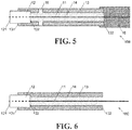
- FIG. 5 shows a schematic configuration view showing a probe 10B for optical measurement according to another modified embodiment of the present invention.
- this probe 10B for optical measurement the portion of the optical fiber 11 in the aforementioned probe 10 for optical measurement positioned on the other end side of the body sleeve 13, that is, the portion of the optical fiber extending outside the body sleeve 13, is covered with a synthetic resin protective tube 16 having flexibility.
- a protective tube 16 By using such a protective tube 16, it is possible to prevent disconnection of the optical fiber 11 due to bending at the outside of the body sleeve 13.
- a similar protective tube 16 may also be provided for a probe for optical measurement having two or more optical fibers such as the probe 10A for optical measurement in the aforementioned modified embodiment.
- the holes 15 are provided in the body sleeve 13. It should be noted, however, that such a hole 15 is not an essential element in the probe for optical measurement of the present invention, and such a hole can be omitted in the same manner as in the probe 10C for optical measurement shown in FIG. 6 .
- the adhesive agent is filled into the gap 134 from the other end side of the body sleeve 13 without suctioning the gas at the time of production. In this case, it is more difficult for the adhesive agent to flow into the gap 134 as compared with the case in which a gas is suctioned, so it is preferable to use an adhesive agent having low viscosity.
- FIG. 6 shows the case in which only one optical fiber is arranged and there exists no protective tube 16. However, two or more optical fibers may be provided and the protective tube 16 may also be provided.
- a solidified adhesive agent is used for the optical fiber fixture 14, but a material formed by solidifying a material having other fluidity may be used.
- a material formed by solidification due to evaporation of a solvent a material formed by solidification due to a chemical reaction between a main agent and a curing agent, a material formed by solidification due to the chemical reaction by heat or light (a thermosetting resin, a light-curable resin), etc., can be used.
Landscapes
- Physics & Mathematics (AREA)
- General Physics & Mathematics (AREA)
- Analytical Chemistry (AREA)
- Health & Medical Sciences (AREA)
- Life Sciences & Earth Sciences (AREA)
- Chemical & Material Sciences (AREA)
- Biochemistry (AREA)
- General Health & Medical Sciences (AREA)
- Immunology (AREA)
- Pathology (AREA)
- Optics & Photonics (AREA)
- Investigating Or Analysing Materials By Optical Means (AREA)
- Mechanical Coupling Of Light Guides (AREA)
Abstract
Description
- The present invention relates to a probe for optical measurement used for measuring concentration, density, partial pressure, molecular species, etc. (hereinafter collectively referred to as "concentration, etc.") of a measurement target gas using a laser absorption spectroscopic method, and also relates to a method of producing the probe for optical measurement.
- As a method of measuring concentration, etc., of a target gas contained in a measurement target gas, an absorption spectroscopic method is known. In an absorption spectroscopic method, measurement light in the absorption wavelength band of a target gas is irradiated to a measurement target gas, and the intensity of the transmitted light is measured. Then, the absorbance of the target gas is obtained from the light absorption amount by the target gas, and the concentration, etc., of the target gas is obtained from the absorbance.
- Such an absorption spectroscopic method is used for measuring concentration, etc., of, for example, oxygen contained in a combustion gas supplied to an engine of an automobile, carbon dioxide contained in an exhaust gas from an engine. In this case, in order to perform the measurement in real time with the engine actually running, a probe is inserted into the combustion chamber of the engine or into the exhaust gas pipe, and the tip of the optical fiber is fixed at a predetermined position for the measurement. Such a probe is also used for measuring concentration, etc., of a gas in a flow path in a fuel cell or in a living body.
- In Patent Document 1, a probe for optical measurement having a ferrule for fixing a tip of an optical fiber is described. In this probe for optical measurement, an optical fiber is inserted into a ferrule so that the tip of the optical fiber is taken out from the tip of the ferrule, and the periphery of the ferrule and the periphery of the portion of the optical fiber on the rear end side (the opposite side of the tip) than the ferrule are covered by a body sleeve formed of a metal tube. There is a gap between the optical fiber and the body sleeve on the rear end side than the ferrule, and a flexible protective tube is inserted in the gap. At the time of measurement, the tip of the probe for optical measurement is inserted into a hole provided in a combustion chamber of an engine, an exhaust gas pipe, etc., and the probe for optical measurement is fixed. With this, the tip of the optical fiber is fixed at a predetermined position in the combustion chamber or the exhaust gas pipe. According to this probe for optical measurement, the optical fiber is covered with the flexible protective tube on the rear end side than the ferrule. This prevents disconnection of the optical fiber due to bending.
- Patent Document 1: Japanese Unexamined Patent Application Publication No.
2016-200647 - For the purpose of preventing an operation of an engine or emission of an exhaust gas from being affected, it is necessary to make a hole for inserting an optical measurement probe to be provided in a measurement target portion such as a combustion chamber of an engine and an exhaust gas pipe as small as possible. However, in the probe for optical measurement described in Patent Document 1, the diameter of the portion of the probe to be inserted into such a hole is determined by the diameter of the body sleeve and the protective tube is inserted in the hole. Therefore, it is difficult to further reduce the diameter of the body sleeve.
- It is an object of the present invention to provide a probe for optical measurement capable of reducing a diameter of the probe while preventing disconnection of an optical fiber and also provide a method of producing such a probe.
- A probe for optical measurement according to the present invention which has been made to solve the aforementioned objects, includes:
- at least one optical fiber;
- a ferrule in which the optical fiber is inserted such that one end of the optical fiber is exposed from one end of the ferrule and the other end side of the optical fiber is exposed from the other end of the ferrule;
- a cylindrical body sleeve having non-flexibility in which a part of at least the other end side of the ferrule is inserted, wherein the body sleeve covers a part of the other end side of the optical fiber; and
- an optical fiber fixture filled in a gap between the optical fiber and the body sleeve and composed of a member formed by solidification of a material having fluidity.
- In the probe for optical measurement according to the present invention, an optical fiber is inserted in the ferrule, and at least a part of the other end side of the ferrule is inserted in the body sleeve. Further, the other end side portion of the optical fiber exposed from the ferrule is covered with the body sleeve. Thus, on the other end side of the optical fiber, a gap is formed between the optical fiber and the body sleeve. The optical fiber fixture is filled in this gap. Such an optical fiber fixture can be produced by filling a material having fluidity in the gap and solidifying the material even in cases where the gap between the optical fiber and the body sleeve is small. For this reason, the diameter of the body sleeve can be reduced. With this, the diameter of the probe for optical measurement can be reduced.
- Also, the optical fiber fixture formed of a solidified adhesive agent is provided outside the optical fiber and the body sleeve having non-flexibility is provided outside the optical fiber fixture. Therefore, disconnection of the optical fiber can also be prevented.
- For the one formed by solidification of a material having fluidity, it is possible to use one solidified due to evaporation of a solvent, one solidified due to a chemical reaction between a main agent and a curing agent, and one solidified due to a chemical reaction by heat or light (e.g., a thermosetting resin, a light-curable resin). For the material, an adhesive agent can be suitably used.
- For the one formed by solidification of a material having fluidity, it is preferable to use one having a low coefficient of thermal expansion, and more preferable to use one formed by solidification of an adhesive agents, such as, e.g., a silicone based adhesive agent and an epoxy based adhesive agent. Note that the mechanical strength of the probe for optical measurement is secured by the body sleeve having non-flexibility. Therefore, no mechanical strength is required for the optical fiber fixture.
- For the material of the body sleeve, metal, ceramics, etc., can be used. For the material of the ferrule, ceramics, glass, metal, etc., can be used.
- The probe for optical measurement according to the present invention is preferably provided with a plurality of optical fibers. For example, the probe for optical measurement may be provided with two optical fibers, wherein one of the optical fibers is used for irradiating irradiation light and the other is used for detecting absorbed light. Alternatively, the probe for optical measurement may be provided with two, three or more optical fibers to measure the absorption of light at different wavelengths for each optical fiber.
- In the probe for optical measurement according to the present invention, the portion of the optical fiber positioned on the other end side than the body sleeve may be covered with a protective tube having flexibility. With this, it is possible to prevent disconnection of the optical fiber due to bending on the other end side than the body sleeve. Note that by not inserting the other end side of the probe for optical measurement than the body sleeve into the hole provided in a measurement target portion, even in cases where the diameter of the probe for optical measurement is increased by the protective tube on the other end side than the body sleeve, measurement can be performed with no problem.
- In the probe for optical measurement according to the present invention, it may be configured such that the body sleeve is provided with a hole filled with the one formed by solidification of a material having fluidity at a position covering a part of the other end side of the optical fiber. Such a hole filled with the one formed by solidification of a material having fluidity is formed in the probe for optical measurement according to the present invention when produced by the method of producing the probe for optical measurement according to the present invention described below.
- A method of producing a probe for optical measurement, comprising:
- providing a hole in a cylindrical body sleeve having non-flexibility;
- inserting an optical fiber in a ferrule such that one end of the optical fiber is exposed from one end of the ferrule and the other end side of the optical fiber is exposed from the other end of the ferrule;
- inserting the ferrule into the body sleeve such that the body sleeve covers a part of the other end side of the optical fiber and the hole is positioned at a position which covers a part of the other end side of the optical fiber;
- filling a material in a gap between the optical fiber and the body sleeve by sucking a gas from the hole while injecting the material having fluidity from an end portion of the body sleeve on the other end side of the optical fiber; and
- solidifying the material in the gap and the hole.
- As the material, an adhesive agent may be suitably used.
- According to the method of producing a probe for optical measurement, it is possible to easily fill a material having fluidity in the gap between the optical fiber and the body sleeve. This makes it possible to reduce this gap, which in turn can reduce the diameter of the probe for optical measurement.
- According to the probe for optical measurement and the method of producing the same, the diameter of the probe for optical measurement can be reduced while preventing disconnection of an optical fiber.
-
-
FIG. 1 is a schematic configuration view showing one embodiment of a probe for optical measurement according to the present invention. -
FIG. 2A to FIG. 2D are schematic views explaining a method of producing the probe for optical measurement of this embodiment. -
FIG. 3 is a schematic configuration view showing one modified embodiment of a probe for optical measurement according to the present invention. -
FIG. 4 is a schematic view showing an example of a mode of usage of a probe for optical measurement of a modified embodiment. -
FIG. 5 is a schematic configuration view showing another modified embodiment of a probe for optical measurement according to the present invention. -
FIG. 6 is a schematic configuration view showing still another modified embodiment of a probe for optical measurement according to the present invention. - With reference to
FIG. 1 to FIG. 6 , embodiments of a probe for optical measurement according to the present invention and its production method will be described. -
FIG. 1 is a schematic configuration view showing aprobe 10 for optical measurement according to this embodiment. Thisprobe 10 for optical measurement is provided with anoptical fiber 11, aferrule 12, abody sleeve 13, and anoptical fiber fixture 14. - The
ferrule 12 is a columnar member made of zirconia, and is provided with a through-hole for inserting theoptical fiber 11 along the axis of the columnar member. InFIG. 1 . a schematic configuration of theprobe 10 for optical measurement is shown as a cross-sectional view taken along a plane parallel to the axis of the columnar member and including the axis. For the material of theferrule 12, ceramics other than zirconia may be used. Alternatively, glass, metal, etc., may also be used. Further, the shape of theferrule 12 is not limited to a columnar shape, and may be a prism shape, etc. Theoptical fiber 11 is inserted in the through-hole of theferrule 12 such that one end of the optical fiber is exposed from oneend 121 of theferrule 12 and the other end side of the optical fiber is pulled out of theother end 122 of theferrule 12. - The
body sleeve 13 is a cylindrical stainless steel member having non-flexibility. For the material of thebody sleeve 13, as long as the material does not have flexibility, metals other than stainless steel may be used, or ceramics or the like may also be used. A part of theferrule 12 on theother end 122 side is inserted into oneend 131 side of thebody sleeve 13. In this embodiment, the inner diameter of the cylindrical member configuring thebody sleeve 13 is made smaller than the outer diameter of theferrule 12 throughout the entire cylindrical member, and the inside of the cylindrical member is subjected to cutting (stepped processing) so that only the portion of the cylindrical member on the oneend 131 side where theferrule 12 is inserted has an inner diameter substantially equal to the outer diameter of theferrule 12. Alternatively, the inner diameter of thebody sleeve 13 may be set to be substantially equal to the outer diameter of theferrule 12 throughout theentire body sleeve 13. As described above, when the inner diameter of thebody sleeve 13 is entirely made substantially equal to the outer diameter offerrule 12 throughout theentire body sleeve 13, stepped processing of thebody sleeve 13 becomes unnecessary, which in turn can reduce the thickness of theentire body sleeve 13. Theoptical fiber 11 extending from theother end 122 side of theferrule 12 is arranged in thebody sleeve 13 and reaches the outside of theother end 132 of thebody sleeve 13. A gap is formed between theoptical fiber 11 and thebody sleeve 13 on theother end 132 side of thebody sleeve 13 than theother end 122 of theferrule 12. Thebody sleeve 13 has a higher rigidness than that of theoptical fiber fixture 14. - The
optical fiber fixture 14 is filled in the gap between theoptical fiber 11 and thebody sleeve 13. With this, theoptical fiber 11 is fixed to thebody sleeve 13. For theoptical fiber fixture 14, a solidified adhesive agent is used in this embodiment. For this adhesive agent, an adhesive agent having heat resistance to temperature in the use environment of theprobe 10 for optical measurement is used. From the viewpoint of easy production, it is desirable to use an adhesive agent having low viscosity. For such an adhesive agent, a silicone based adhesive agent, such as RTV silicone rubber (KE-1308), may be suitably used. Instead of a silicone based adhesive agent, other adhesive agents, such as, e.g., epoxy based adhesive agent, may be used. - At a position of the
body sleeve 13 covering a part of the other end side of theoptical fiber 11, in other words, at a position of thebody sleeve 13 closer to theother end 132 thereof than theother end 122 of theferrule 12 inserted in thebody sleeve 13, holes 15 are provided. In this embodiment, twoholes 15 are provided, but the number ofholes 15 may be one or three or more. In the same manner as in theoptical fiber fixture 14, theholes 15 are filled with a solidified adhesive agent. - Next, with reference to
FIG. 2A to FIG. 2D , a method for producing aprobe 10 for optical measurement according to this embodiment will be described. - First, a through-hole is formed in the
ferrule 12 made of ceramics along the axis thereof, and theoptical fiber 11 is inserted into this through-hole (FIG. 2A ). At that time, the insertion operation is performed such that one end of theoptical fiber 11 is exposed from one end of theferrule 12 and the other end side of theoptical fiber 11 is pulled out of theother end 122 of theferrule 12. - Further, holes 15 are drilled in a
body sleeve 13 formed of a metal columnar member having non-flexibility, At the same time, the inner periphery of thebody sleeve 13 is subjected to cutting so that the inner diameter of thebody sleeve 13 on the oneend 131 side becomes substantially equal to the outer diameter of theferrule 12 to thereby form a fitting portion 133 (FIG. 2B ). - Next, the other end side of the
optical fiber 11 is passed through the inside of thebody sleeve 13 from the oneend 131 side of thebody sleeve 13, and theferrule 12 is fitted in thefitting portion 133 of the body sleeve 13 (FIG. 2C ). As a result, on theother end 132 side of thebody sleeve 13 than theferrule 12, the other end side of theoptical fiber 11 is arranged in a state in which agap 134 is provided between the other end side of theoptical fiber 11 and thebody sleeve 13. - Subsequently, while supplying an adhesive agent to the
gap 134 from theother end 132 side of thebody sleeve 13, a gas is sucked from theholes 15 using a vacuum pump (FIG. 2D ). This allows the adhesive agent to run through thegap 134 and fill thegap 134 with the adhesive agent. At that time, by using a low viscosity adhesive agent as described above, it is possible to more assuredly fill thegap 134 with the adhesive agent. Theholes 15 are also filled with the adhesive agent. Thereafter, theoptical fiber fixture 14 is produced by solidifying the adhesive agent filled in thegap 134. Through the above steps, theprobe 10 for optical measurement of this embodiment is produced. - According to the probe for optical measurement and its production method of this embodiment, it is easy to fill the adhesive agent in the
gap 134 between theoptical fiber 11 and thebody sleeve 13. This enables to reduce thegap 134, which in turn can reduce the diameter of theprobe 10 for optical measurement. -
FIG. 3 shows a schematic configuration view showing aprobe 10A for optical measurement according to a modified embodiment of the present invention. Thisprobe 10A for optical measurement is provided with two optical fibers, i.e., a single modeoptical fiber 111 and a multimodeoptical fiber 112. Hereinafter, these two optical fibers are collectively referred to as "optical fiber 11A". In the same manner as in theoptical fiber 11 of theprobe 10 for optical measurement, theoptical fiber 11A is inserted into the through-hole of theferrule 12 such that one end thereof is exposed from the oneend 121 of theferrule 12 and the other end side thereof is pulled out of theother end 122 of theferrule 12. Here, theferrule 12 may be provided with a total of two through-holes for respective optical fibers, or may be provided with a single through-hole into which two optical fibers are inserted. Each component of theprobe 10A for optical measurement other than theoptical fiber 11A (and theferrule 12 in the case of providing two through-holes) is the same as that of the above-describedprobe 10 for optical measurement. -
FIG. 4 shows an example of a mode of usage of theprobe 10A for optical measurement of a modified embodiment. A through-hole 32 having an inner diameter substantially equal to the outer diameter of thebody sleeve 13 is provided in thewall 31 of the housing body, such as an engine and an exhaust tube, in which the measurement target gas is present in the internalmeasurement target space 30, and anoptical window 33 is provided at the opening portion on themeasurement target space 30 side of the through-hole 32. Theprobe 10A for optical measurement is inserted into the through-hole 32 from the outside of the housing body in a state in which the one end side of theferrule 12 and theoptical fiber 11A is directed to themeasurement target space 30 side. Alight source 21 is connected to the other end of the single modeoptical fiber 111, and adetector 22 is connected to the other end of the multimodeoptical fiber 112. In this embodiment, thelight source 21 is a light source for generating infrared light in a wavelength band corresponding to the absorption wavelength band of the target gas included in the measurement target gas. The infrared light is irradiated to the measurement target gas in themeasurement target space 30 through the single modeoptical fiber 111 and theoptical window 33. Thedetector 22 is configured to detect the intensity of the transmitted light and the reflected light for each wavelength after the measurement target gas in themeasurement target space 30 absorbs the infrared light in the absorption wavelength band by the measurement target gas. The transmitted light and reflected light of the measurement target gas in themeasurement target space 30 are input to thedetector 22 through theoptical window 33 and the multimodeoptical fiber 112. - In the
probe 10A for optical measurement of this modified example, two optical fibers are provided, but three or more optical fibers may be provided. Thus, for example, the absorption of light at different wavelengths for each optical fiber can be measured. -
FIG. 5 shows a schematic configuration view showing aprobe 10B for optical measurement according to another modified embodiment of the present invention. In thisprobe 10B for optical measurement, the portion of theoptical fiber 11 in theaforementioned probe 10 for optical measurement positioned on the other end side of thebody sleeve 13, that is, the portion of the optical fiber extending outside thebody sleeve 13, is covered with a synthetic resinprotective tube 16 having flexibility. By using such aprotective tube 16, it is possible to prevent disconnection of theoptical fiber 11 due to bending at the outside of thebody sleeve 13. A similarprotective tube 16 may also be provided for a probe for optical measurement having two or more optical fibers such as theprobe 10A for optical measurement in the aforementioned modified embodiment. - In the embodiments described above, the
holes 15 are provided in thebody sleeve 13. It should be noted, however, that such ahole 15 is not an essential element in the probe for optical measurement of the present invention, and such a hole can be omitted in the same manner as in theprobe 10C for optical measurement shown inFIG. 6 . In this case, the adhesive agent is filled into thegap 134 from the other end side of thebody sleeve 13 without suctioning the gas at the time of production. In this case, it is more difficult for the adhesive agent to flow into thegap 134 as compared with the case in which a gas is suctioned, so it is preferable to use an adhesive agent having low viscosity.FIG. 6 shows the case in which only one optical fiber is arranged and there exists noprotective tube 16. However, two or more optical fibers may be provided and theprotective tube 16 may also be provided. - The present invention is not limited to the above-described embodiments, but can be appropriately modified within the scope of the gist of the present invention. For example, in the above-described embodiments, a solidified adhesive agent is used for the
optical fiber fixture 14, but a material formed by solidifying a material having other fluidity may be used. As such, a material formed by solidification due to evaporation of a solvent, a material formed by solidification due to a chemical reaction between a main agent and a curing agent, a material formed by solidification due to the chemical reaction by heat or light (a thermosetting resin, a light-curable resin), etc., can be used. -
- 10, 10A, 10B, 10C:
- probe for optical measurement
- 11, 11A:
- optical fiber
- 111:
- single mode optical fiber
- 112:
- multimode optical fiber
- 12:
- ferrule
- 121:
- one end of a ferrule
- 122:
- the other end of the ferrule
- 13:
- body sleeve
- 131:
- one end of a body sleeve
- 132:
- the other end of a body sleeve
- 133:
- fitting portion
- 134:
- gap
- 14:
- optical fiber fixture
- 15:
- hole
- 16:
- protective tube
- 21:
- light source
- 22:
- detector
- 30:
- measurement target space
- 31:
- wall
- 32:
- through-hole
- 33:
- optical window
Claims (8)
- A probe for optical measurement, comprising:at least one optical fiber;a ferrule in which the optical fiber is inserted such that one end of the optical fiber is exposed from one end of the ferrule and the other end side of the optical fiber is exposed from the other end of the ferrule;a cylindrical body sleeve having non-flexibility in which a part of at least the other end side of the ferrule is inserted, wherein the body sleeve covers a part of the other end side of the optical fiber; andan optical fiber fixture filled in a gap between the optical fiber and the body sleeve and composed of a member formed by solidification of a material having fluidity.
- The probe for optical measurement as recited in claim 1,
wherein the material is an adhesive agent. - The probe for optical measurement as recited in claim 1 or 2,
wherein the optical fiber fixture fixes the optical fiber to the body sleeve. - The probe for optical measurement as recited in one of claims 1-3,
wherein the at least one optical fiber comprises a plurality of optical fibers. - The probe for optical measurement as recited in one of claims 1-4,
wherein a part of the optical fiber located closer to the other end side of the optical fiber than the body sleeve is covered with a protective tube having flexibility. - The probe for optical measurement as recited in one of claims 1-5,
wherein the body sleeve is provided with a hole filled with the solidified material at a position covering a part of the other end side of the optical fiber. - A method of producing a probe for optical measurement, comprising:providing a hole in a cylindrical body sleeve having non-flexibility;inserting an optical fiber in a ferrule such that one end of the optical fiber is exposed from one end of the ferrule and the other end side of the optical fiber is exposed from the other end of the ferrule;inserting the ferrule into the body sleeve such that the body sleeve covers a part of the other end side of the optical fiber and the hole is positioned at a position which covers a part of the other end side of the optical fiber;filling a material in a gap between the optical fiber and the body sleeve by sucking a gas from the hole while injecting the material having fluidity from an end portion of the body sleeve on the other end side of the optical fiber; andsolidifying the material in the gap and the hole.
- The method of producing a probe for optical measurement as recited in claim 7,
wherein the material is an adhesive agent.
Applications Claiming Priority (2)
| Application Number | Priority Date | Filing Date | Title |
|---|---|---|---|
| JP2018067637 | 2018-03-30 | ||
| JP2019058286A JP2019184593A (en) | 2018-03-30 | 2019-03-26 | Probe for optical measurement and method for manufacturing the same |
Publications (1)
| Publication Number | Publication Date |
|---|---|
| EP3546929A1 true EP3546929A1 (en) | 2019-10-02 |
Family
ID=65995649
Family Applications (1)
| Application Number | Title | Priority Date | Filing Date |
|---|---|---|---|
| EP19165729.5A Withdrawn EP3546929A1 (en) | 2018-03-30 | 2019-03-28 | Probe for optical measurement and method of producing the same |
Country Status (2)
| Country | Link |
|---|---|
| US (1) | US10712502B2 (en) |
| EP (1) | EP3546929A1 (en) |
Citations (3)
| Publication number | Priority date | Publication date | Assignee | Title |
|---|---|---|---|---|
| WO2014111990A1 (en) * | 2013-01-21 | 2014-07-24 | コニカミノルタ株式会社 | Probe, spectrometry device and diagnostic system |
| JP2016138913A (en) * | 2015-01-26 | 2016-08-04 | 京セラ株式会社 | Optical fiber and light guide device with ferrule |
| JP2016200647A (en) | 2015-04-07 | 2016-12-01 | フジクラ電装株式会社 | Ferrule with optical fiber and optical apparatus |
Family Cites Families (1)
| Publication number | Priority date | Publication date | Assignee | Title |
|---|---|---|---|---|
| CN105334582A (en) * | 2014-07-01 | 2016-02-17 | 泰科电子(上海)有限公司 | Insertion core device and manufacture method thereof |
-
2019
- 2019-03-28 US US16/368,256 patent/US10712502B2/en not_active Expired - Fee Related
- 2019-03-28 EP EP19165729.5A patent/EP3546929A1/en not_active Withdrawn
Patent Citations (3)
| Publication number | Priority date | Publication date | Assignee | Title |
|---|---|---|---|---|
| WO2014111990A1 (en) * | 2013-01-21 | 2014-07-24 | コニカミノルタ株式会社 | Probe, spectrometry device and diagnostic system |
| JP2016138913A (en) * | 2015-01-26 | 2016-08-04 | 京セラ株式会社 | Optical fiber and light guide device with ferrule |
| JP2016200647A (en) | 2015-04-07 | 2016-12-01 | フジクラ電装株式会社 | Ferrule with optical fiber and optical apparatus |
Also Published As
| Publication number | Publication date |
|---|---|
| US20190302372A1 (en) | 2019-10-03 |
| US10712502B2 (en) | 2020-07-14 |
Similar Documents
| Publication | Publication Date | Title |
|---|---|---|
| US8123403B2 (en) | Temperature sensor probe and manufacturing method of the same | |
| US6104485A (en) | Method and apparatus for optical measurement of very small fluid samples | |
| EP2773259B1 (en) | Raman spectroscopy probe | |
| KR102127110B1 (en) | Optical fiber probe, optical fiber measuring device and clearance control system | |
| US9518894B2 (en) | Device for measuring vibration amplitudes of the blade tips in a turbomachine | |
| CN109444074B (en) | Laser spectrum absorption probe device with self-calibration function and measurement method thereof | |
| JP2019504352A (en) | Photonic crystal fiber assembly | |
| US20170105626A1 (en) | Optical fiber cable, method of manufacturing the same, and light source module including the same | |
| JP5805739B2 (en) | Flow cell | |
| FI95322B (en) | Spectroscopic measuring sensor for the analysis of media | |
| EP3067686A1 (en) | Optical element, transmission probe, sample container, optical device, and immersion transmission measurement method | |
| EP2265161A1 (en) | Biopsy device | |
| CN101806725A (en) | Suspension-core optical fiber-based gas absorption spectrum line reference device | |
| US10712502B2 (en) | Probe for optical measurement and method of producing the same | |
| JP2009250825A (en) | Probe for absorbance measurement, and absorptiometer | |
| KR20130019889A (en) | Reflective probe type apparatus for detecting gas and method for detecting gas using optical fiber with hollow core | |
| US8920150B2 (en) | Pin having light guide for injection mold | |
| JP6153937B2 (en) | Measuring chamber for optical sensors for determining the concentration of substances in mammalian interstitial fluid | |
| JP2019184593A (en) | Probe for optical measurement and method for manufacturing the same | |
| CN103038683A (en) | Optical collimator and optical connector using same | |
| US20150148689A1 (en) | Optical Fiber Assembly, Method Of Fabricating Same, And Probe | |
| JP3997502B2 (en) | Optical probe assembly | |
| CN103827643B (en) | Heads for Evanescent Wave Fiber Optic Sensors | |
| JP5469191B2 (en) | Optical component, and optical fiber amplifier and laser device using the same | |
| WO2017037899A1 (en) | Analysis device and exhaust gas treatment device |
Legal Events
| Date | Code | Title | Description |
|---|---|---|---|
| PUAI | Public reference made under article 153(3) epc to a published international application that has entered the european phase |
Free format text: ORIGINAL CODE: 0009012 |
|
| STAA | Information on the status of an ep patent application or granted ep patent |
Free format text: STATUS: REQUEST FOR EXAMINATION WAS MADE |
|
| 17P | Request for examination filed |
Effective date: 20190419 |
|
| AK | Designated contracting states |
Kind code of ref document: A1 Designated state(s): AL AT BE BG CH CY CZ DE DK EE ES FI FR GB GR HR HU IE IS IT LI LT LU LV MC MK MT NL NO PL PT RO RS SE SI SK SM TR |
|
| AX | Request for extension of the european patent |
Extension state: BA ME |
|
| GRAP | Despatch of communication of intention to grant a patent |
Free format text: ORIGINAL CODE: EPIDOSNIGR1 |
|
| STAA | Information on the status of an ep patent application or granted ep patent |
Free format text: STATUS: GRANT OF PATENT IS INTENDED |
|
| INTG | Intention to grant announced |
Effective date: 20220610 |
|
| STAA | Information on the status of an ep patent application or granted ep patent |
Free format text: STATUS: THE APPLICATION IS DEEMED TO BE WITHDRAWN |
|
| 18D | Application deemed to be withdrawn |
Effective date: 20221021 |