EP3546885B1 - Gnss device - Google Patents
Gnss device Download PDFInfo
- Publication number
- EP3546885B1 EP3546885B1 EP19163113.4A EP19163113A EP3546885B1 EP 3546885 B1 EP3546885 B1 EP 3546885B1 EP 19163113 A EP19163113 A EP 19163113A EP 3546885 B1 EP3546885 B1 EP 3546885B1
- Authority
- EP
- European Patent Office
- Prior art keywords
- tilt
- receiver
- calibration
- pole
- screen
- Prior art date
- Legal status (The legal status is an assumption and is not a legal conclusion. Google has not performed a legal analysis and makes no representation as to the accuracy of the status listed.)
- Active
Links
Images



Classifications
-
- G—PHYSICS
- G01—MEASURING; TESTING
- G01S—RADIO DIRECTION-FINDING; RADIO NAVIGATION; DETERMINING DISTANCE OR VELOCITY BY USE OF RADIO WAVES; LOCATING OR PRESENCE-DETECTING BY USE OF THE REFLECTION OR RERADIATION OF RADIO WAVES; ANALOGOUS ARRANGEMENTS USING OTHER WAVES
- G01S19/00—Satellite radio beacon positioning systems; Determining position, velocity or attitude using signals transmitted by such systems
- G01S19/38—Determining a navigation solution using signals transmitted by a satellite radio beacon positioning system
- G01S19/39—Determining a navigation solution using signals transmitted by a satellite radio beacon positioning system the satellite radio beacon positioning system transmitting time-stamped messages, e.g. GPS [Global Positioning System], GLONASS [Global Orbiting Navigation Satellite System] or GALILEO
- G01S19/42—Determining position
-
- G—PHYSICS
- G01—MEASURING; TESTING
- G01C—MEASURING DISTANCES, LEVELS OR BEARINGS; SURVEYING; NAVIGATION; GYROSCOPIC INSTRUMENTS; PHOTOGRAMMETRY OR VIDEOGRAMMETRY
- G01C15/00—Surveying instruments or accessories not provided for in groups G01C1/00 - G01C13/00
- G01C15/02—Means for marking measuring points
- G01C15/06—Surveyors' staffs; Movable markers
-
- G—PHYSICS
- G01—MEASURING; TESTING
- G01C—MEASURING DISTANCES, LEVELS OR BEARINGS; SURVEYING; NAVIGATION; GYROSCOPIC INSTRUMENTS; PHOTOGRAMMETRY OR VIDEOGRAMMETRY
- G01C9/00—Measuring inclination, e.g. by clinometers, by levels
- G01C9/02—Details
-
- G—PHYSICS
- G01—MEASURING; TESTING
- G01S—RADIO DIRECTION-FINDING; RADIO NAVIGATION; DETERMINING DISTANCE OR VELOCITY BY USE OF RADIO WAVES; LOCATING OR PRESENCE-DETECTING BY USE OF THE REFLECTION OR RERADIATION OF RADIO WAVES; ANALOGOUS ARRANGEMENTS USING OTHER WAVES
- G01S19/00—Satellite radio beacon positioning systems; Determining position, velocity or attitude using signals transmitted by such systems
- G01S19/01—Satellite radio beacon positioning systems transmitting time-stamped messages, e.g. GPS [Global Positioning System], GLONASS [Global Orbiting Navigation Satellite System] or GALILEO
- G01S19/13—Receivers
- G01S19/14—Receivers specially adapted for specific applications
-
- G—PHYSICS
- G01—MEASURING; TESTING
- G01S—RADIO DIRECTION-FINDING; RADIO NAVIGATION; DETERMINING DISTANCE OR VELOCITY BY USE OF RADIO WAVES; LOCATING OR PRESENCE-DETECTING BY USE OF THE REFLECTION OR RERADIATION OF RADIO WAVES; ANALOGOUS ARRANGEMENTS USING OTHER WAVES
- G01S19/00—Satellite radio beacon positioning systems; Determining position, velocity or attitude using signals transmitted by such systems
- G01S19/01—Satellite radio beacon positioning systems transmitting time-stamped messages, e.g. GPS [Global Positioning System], GLONASS [Global Orbiting Navigation Satellite System] or GALILEO
- G01S19/13—Receivers
- G01S19/23—Testing, monitoring, correcting or calibrating of receiver elements
-
- G—PHYSICS
- G01—MEASURING; TESTING
- G01S—RADIO DIRECTION-FINDING; RADIO NAVIGATION; DETERMINING DISTANCE OR VELOCITY BY USE OF RADIO WAVES; LOCATING OR PRESENCE-DETECTING BY USE OF THE REFLECTION OR RERADIATION OF RADIO WAVES; ANALOGOUS ARRANGEMENTS USING OTHER WAVES
- G01S19/00—Satellite radio beacon positioning systems; Determining position, velocity or attitude using signals transmitted by such systems
- G01S19/38—Determining a navigation solution using signals transmitted by a satellite radio beacon positioning system
- G01S19/39—Determining a navigation solution using signals transmitted by a satellite radio beacon positioning system the satellite radio beacon positioning system transmitting time-stamped messages, e.g. GPS [Global Positioning System], GLONASS [Global Orbiting Navigation Satellite System] or GALILEO
- G01S19/42—Determining position
- G01S19/45—Determining position by combining measurements of signals from the satellite radio beacon positioning system with a supplementary measurement
-
- G—PHYSICS
- G01—MEASURING; TESTING
- G01S—RADIO DIRECTION-FINDING; RADIO NAVIGATION; DETERMINING DISTANCE OR VELOCITY BY USE OF RADIO WAVES; LOCATING OR PRESENCE-DETECTING BY USE OF THE REFLECTION OR RERADIATION OF RADIO WAVES; ANALOGOUS ARRANGEMENTS USING OTHER WAVES
- G01S19/00—Satellite radio beacon positioning systems; Determining position, velocity or attitude using signals transmitted by such systems
- G01S19/38—Determining a navigation solution using signals transmitted by a satellite radio beacon positioning system
- G01S19/39—Determining a navigation solution using signals transmitted by a satellite radio beacon positioning system the satellite radio beacon positioning system transmitting time-stamped messages, e.g. GPS [Global Positioning System], GLONASS [Global Orbiting Navigation Satellite System] or GALILEO
- G01S19/40—Correcting position, velocity or attitude
Definitions
- OK is displayed on the screen, and by tapping this, the screen shifts to the calibration screen illustrated in Fig. 7 .
- OK is displayed.
- Step S204 when compass adjustment is required in Step S204, the processing shifts to Step S205, and when compass adjustment is not required, the processing shifts to Step S206.
- Steps S201 to S207 are repeated until adjustments of the respective items become unnecessary.
- the calibration processing is ended, and the processing returns to the original Step S103, and shifts to Step S104.
- Step S110 the coordinates of the ground-contact point P of the pole 4 calculated in Step S109 are illustrated as the pin mark 42 in the screen area 41, and displayed as numeric values in the screen area 44 (refer to Fig. 5 ).
- Step S113 when the operator taps each icon or instructs execution of calibration from the menu screen, the screen of the display unit 31 shifts to a calibration screen, and calibration processing starts.
- Step S103 Steps S201 to S207 are executed as calibration processing, and when the calibration processing is ended, the processing returns to Step S106.
Landscapes
- Engineering & Computer Science (AREA)
- Radar, Positioning & Navigation (AREA)
- Remote Sensing (AREA)
- Physics & Mathematics (AREA)
- General Physics & Mathematics (AREA)
- Computer Networks & Wireless Communication (AREA)
- Position Fixing By Use Of Radio Waves (AREA)
Description
- The present invention relates to a GNSS device, particularly to a GNSS device with a tilt sensor.
- In recent years, a GNSS device with a built-in tilt sensor has been used at survey sites.
- For example, a device described in
Patent Literature 1 includes an electronic tilt sensor, an imaging device, and a display unit, and displays, together with imaging data, a vertically lower position of the device from a tilt detected by the electronic tilt sensor on the display unit. -
WO 2014055428 discloses a GNSS receiver with tilt sensor attached to a pole. A virtual bubble level tube is displayed with colors indicating measured tilt values. The position of the ground contact point is calculated based on GNSS position and measured tilt. TEP2487458A2 discloses a mobile device with electronic compass function, accelerometer determining orientation of the device with respect to gravity (e.g., tilt), GNSS receiver and display. An application may request the electronic compass to be calibrated. The user interacts then with a displayed menu which leads to a calibration user interface. - Patent Literature 1:
Japanese Published Unexamined Patent Application No. 2012-225696 - However, a GNSS device with a built-in tilt sensor has been released in recent years, but has a problem that the display on the screen is difficult to understand and lacks operability.
- The present invention was made in view of these circumstances, and an object thereof is to provide a GNSS device with an electronic tilt sensor which is high in operability and usability.
- In order to attain the above-described object, a GNSS device according to an aspect of the present invention includes a tilt sensor capable of measuring a tilt, an electronic compass capable of measuring a direction, a GNSS antenna capable of acquiring positional information, and a display unit capable of displaying information, and is configured so that when the tilt sensor or the electronic compass requests calibration for adjustment, an icon calling attention is displayed on a screen of the display unit, and when the icon is tapped, the screen of the display unit shifts to a calibration screen.
- According to this aspect, the screen can be immediately shifted to a calibration screen when necessary, so that high work efficiency and high usability are obtained.
- The display unit displays a tilt measured by the tilt sensor as an electronic bubble tube, and displays a bubble in the electronic bubble tube in a color corresponding to a level of the tilt measured by the tilt sensor.
- According to this aspect, the degree of the tilt of the GNSS device can be judged by the color of the bubble, visibility and operator understanding are excellent, and the device is user-friendly.
- The tilt sensor and the GNSS antenna are attached to a pole, and the GNSS device has a correction function to calculate positional information of a ground-contact point of the pole from a tilt of the pole measured by the tilt sensor and an attaching height of the GNSS antenna based on positional information acquired by the GNSS antenna, and the display unit displays the electronic bubble tube with a bubble in a color different from when using the correction function and when not using the correction function.
- According to this aspect, an operator can judge whether the correction function is ON or OFF at a glance.
- Even while the GNSS antenna acquires positional information, when the tilt sensor or electronic compass requests calibration for adjustment, the icon calling attention is displayed on the display unit.
- Even during acquisition of positional information, when calibration is necessary, such necessity is informed by being displayed, and in response to tapping, calibration can be performed immediately, so that wasteful operation is avoided, and the device becomes high in usability.
- As is clear from the description above, according to the present invention, a GNSS device with a tilt sensor which is easy to operate and has high usability is provided.
-
-
Fig. 1 is a schematic view of a GNSS device according to an embodiment. -
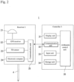
Fig. 2 is a block diagram of the same GNSS device. -
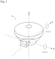
Fig. 3 is an explanatory view to describe axes and tilts of a receiver. -
Fig. 4 is an explanatory view to describe a method of calculating a correction value. -
Fig. 5 is an example of a display screen of a display unit. -
Fig. 6 is an example of the display screen of the display unit. -
Fig. 7 is an example of the display screen of the display unit. -
Fig. 8 is an example of the display screen of the display unit. -
Fig. 9 is an example of the display screen of the display unit. -
Fig. 10 is an example of the display screen of the display unit. -
Figs. 11 are explanatory views to describe colors of a bubble in an electronic bubble tube. -
Fig. 12 is an operation flowchart of the GNSS device. -
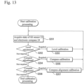
Fig. 13 is a flowchart of calibration processing. - Hereinafter, a detailed embodiment of the present disclosed configuration is described with reference to the drawings. The embodiment does not limit the invention but is an illustration, and all features described in the embodiment and combinations thereof are not necessarily essential of the invention.
-
Fig. 1 is a schematic view of aGNSS device 1 according to an embodiment of the present invention, andFig. 2 is a block diagram of theGNSS device 1. - The GNSS
device 1 is a positioning system using a GNSS (Global Navigation Satellite System). In the present embodiment, positioning is performed by using a GPS (Global Positioning System) as one of GNSS. - The
GNSS device 1 includes areceiver 2, acontroller 3, and apole 4. Thereceiver 2 and thecontroller 3 are configured separately, and connected wirelessly or in a wired manner using a cable. - The
pole 4 has a horizontal surface at an upper end, and a leg suspended from the horizontal surface. Thereceiver 2 is supported on a center (on the vertical line of a ground-contact point P) of the horizontal surface of thepole 4. - The
receiver 2 is a device to receive a signal transmitted from a GPS satellite, and includes aGNSS antenna 21, aGNSS receiver 22, atilt sensor 23, anelectronic compass 24, and acommunication unit 25. - The GNSS
antenna 21 is a device to receive radio waves, and receives a GPS signal transmitted from a GPS satellite, and inputs the received GPS signal into the GNSSreceiver 22. - The
GNSS receiver 22 converts a received radio wave (GPS signal) into an electric signal. The converted signal is input into the arithmetic control unit of thecontroller 3 via thecommunication unit 25 described later. - The
tilt sensor 23 is a sensor to measure a tilt angle from a reference state. In the present embodiment, thetilt sensor 23 consists of an acceleration sensor capable of measuring an acceleration, and measures a gravity acceleration to measure a tilt. As illustrated inFig. 3 , a state where a bottom surface of thereceiver 2 is placed horizontally on the horizontal surface (horizontal state) is set as a reference state, and a tilt Tilt X around a direction (around the Xk axis inFig. 3 ) along the horizontal surface from the horizontal state of thereceiver 2, and a tilt Tilt Y around another direction (around the Yk axis inFig. 3 ) orthogonal to the one direction along the horizontal surface, can be measured. The tilt sensor is not limited to an acceleration sensor, and may consist of, for example, a gyro sensor, as long as it can measure a tilt angle. - The
electronic compass 24 is a direction sensor using a semiconductor, and calculates a direction by detecting the north-south geomagnetism. Publicly-known electronic compasses using elements such as an MR element or a GMR element can be used regardless of the type of compass. - The
communication unit 25 is a data transmitting/receiving device capable of making wireless communication with acommunication unit 32 of thecontroller 3. Thecommunication unit 25 transmits a GPS signal input into theGNSS receiver 22 and data measured by thetilt sensor 23 and theelectronic compass 24 to thecommunication unit 32, and receives a command from thecontroller 3. - The
tilt sensor 23 and theelectronic compass 24 require calibration sometimes before use. The installed sensors are highly sensitive and easily influenced by magnetic fields and radio waves in the outside air. Therefore, these fields or waves may affect the sensitivity of sensors and make them go out of order, and to restore the sensors into normal states, fine adjustment (calibration) required. Due to the characteristics of thetilt sensor 23 and theelectronic compass 24, calibration is required when starting the use of thereceiver 2. - The
controller 3 is a device to calculate three-dimensional positioning data from signals received by thereceiver 2, and includes adisplay unit 31, thecommunication unit 32, aninput unit 33, astorage unit 34, and anarithmetic control unit 35. - The
display unit 31 and theinput unit 33 are interfaces of theGNSS device 1. Inputs of various operation instructions can be made with theinput unit 33, and settings of commands and confirmation of an observation status and operation results can be performed with the display unit. In the present embodiment, thedisplay unit 31 is a touch-panel type, and an operator can input a command by tapping the screen, and thedisplay unit 31 also serves as theinput unit 33. - The
communication unit 32 is a wireless data transmitting/receiving device like thecommunication unit 25, and can receive data from thecommunication unit 25 and transmit commands under control of thearithmetic control unit 35. - The
arithmetic control unit 35 is, for example, a microcontroller with a CPU, a ROM, and a RAM, etc., mounted on an integrated circuit, and controls theentire GNSS device 1 such as execution of commands for thedisplay unit 31, calculation of three-dimensional positioning data by using GPS signals received by thereceiver 2, etc. There are various methods of calculating three-dimensional positioning data from GPS signals, and the methods are conventionally known, so that detailed description thereof is omitted. In thestorage unit 34, various programs for the arithmetic processing described above are stored. - The
arithmetic control unit 35 calculates highly accurate three-dimensional positioning data (coordinates) of an installation point of the receiver 2 (origin O inFig. 3 ) from received GPS signals. However, the data is coordinates of the installation point of thereceiver 2, and what should be calculated at a survey site in actuality is a ground-contact point P of thepole 4. Therefore, a correction value is obtained based on detection results of thetilt sensor 23 and theelectronic compass 24, and the coordinates of the origin O are corrected to calculate coordinates of the ground-contact point P. Hereinafter, this correction is referred to as tilt correction. -
Fig. 4 is an explanatory view to describe a method of calculating a correction value. To calculate a ground-contact point P (X', Y', Z') of thepole 4 from the coordinates (X, Y, Z) of the origin O of thereceiver 2, first, from tilts (Tilt X) and (Tilt Y) measured by thetilt sensor 23 and a vertical height Ah of thepole 4, relative differences (dXk, dYk, dZk) on local coordinate axes of thereceiver 2 are obtained. - As illustrated in
Fig. 4(A) and Fig. 4(B) ,

pole 4 is Tilt A, and a difference is dA (refer toFig. 4(C) and Fig. 4(D) ),


- Next, by using a displacement angle T (a displacement angle between a direction of the axis Yk of the
receiver 2 and an actual direction Y) measured by theelectronic compass 24, the coordinate axes of thereceiver 2 are rotated, and correction values (Xd, Yd, Zd) in a global coordinate system are obtained. - As illustrated in
Fig. 4(E) ,


pole 4 are as follows.



pole 4 are calculated is performed. - When tilt correction is performed, as three-dimensional position data of the
receiver 2, the ground-contact point P is displayed on thedisplay unit 31. When tilt correction is not performed, a virtual origin O' (refer toFig. 4(F) ) hanging down by the vertical height Ah of thepole 4 from the origin O of thereceiver 2 is displayed as three-dimensional position data. -
Fig. 5 to Fig. 10 illustrate examples of display results of thedisplay unit 31. - A
screen area 41 inFig. 5 shows a real-time kinematic (RTK) observation screen, and atriangular mark 43 denotes a known point, apin mark 42 denotes the device's own observation point, and an operator can visually grasp a positional relationship. Ascreen area 44 shows three-dimensional position data (time JST and coordinates X, Y, H) of thereceiver 2 measured from thereceiver 2. - As three-dimensional position data in the
screen area 44, display of calculated coordinates of the virtual origin O' of thereceiver 2 and display of coordinates of the ground-contact point P of thepole 4 by tilt correction can be selectively performed. When tilt correction is performed, anindication 46 indicating "Under tilt correction" is displayed at a lower portion. - An
icon 47 is displayed only when an abnormality or malfunction of thetilt sensor 23 is detected, and anicon 48 is displayed only when an abnormality or malfunction of theelectronic compass 24 is detected, and both of these icons are to request calibration. By tapping theicon 47 oricon 48, the screen shifts to a calibration screen illustrated inFig. 7 . - In conventional screen display, even when a mark urging calibration is displayed, shifting to the calibration screen can be made only from a menu screen, so that it is required that the screen is returned to the menu screen once, and then by selecting calibration, the menu screen is shifted to the calibration screen, and this process is troublesome. Direct shifting to the calibration screen in response to tapping on the
icon - An
electronic bubble tube 45 is displayed based on tilt data measured by thetilt sensor 23. When abubble 45A is at the center, it means horizontal to a reference plane, and an operator can instinctively grasp a tilt state of thereceiver 2. - The
bubble 45A of theelectronic bubble tube 45 is displayed in a color that differs depending on the level of a tilt angle of the receiver 2 (pole 4).Figs. 11 illustrate examples of display of thebubble 45A. In tilt correction, a range of tilt angle to be subjected to tilt correction can be set, and for example, it is configured so that an upper limit of the range can be selected among 5°, 10°, and 15°, or a desired angle can be input.Fig. 11(A) and Fig. 11(B) illustrate a case where an upper limit of tilt correction is set to 15°. - As illustrated in
Fig. 11(A) , thebubble 45A is displayed in a color that differs from the inside and the outside of the range of the tilt correction. In a case of setting with tilt correction being ON, when the tilt angle is 0° or more and less than 15°, agreen bubble 45A is displayed, and when the tilt angle is 15° or more, ared bubble 45A is displayed. By differing the color depending on whether the current tilt angle of thereceiver 2 is out of the tilt correction range or within the tilt correction range, an operator can grasp a status at a glance. - Even in a case of setting with tilt correction being OFF, the same angle of 15° is used as a judgment criterion, and when the tilt angle is 0° or more and less than 15°, a
blue bubble 45A is displayed, and when the tilt angle is 15° or more, ared bubble 45A is displayed. By differing the color of thebubble 45A depending on ON/OFF of setting of tilt correction, an operator can grasp the setting status at a glance. In the case of an excessive tilt angle (15° or more), ared bubble 45A is displayed in both of setting with tilt correction being ON and setting with tilt correction being OFF to call attention to an operator. -
Fig. 11(B) illustrates another display example of thebubble 45A, and a tilt level is shown by changing a color density according to the level of a tilt of the receiver 2 (pole 4). The color of thebubble 45A is increased in density in increments of 5° of the tilt angle. When the tilt angle is in a range of 0° to 5°, the bubble has no color and is displayed as a white circle, and as the angle increases, the color density increases, and when the tilt angle reaches 15° or more and comes out of the range of tilt correction, the bubble is displayed as a black circle. An operator can grasp the level of the tilt angle based on a color density. - By the color of the
bubble 45A, a user can judge the setting and status, and this configuration is high in visibility and user-friendly. -
Fig. 6 illustrates a screen at the time of static observation, and a reception status such as the number of GPS satellites from which signals are received, and the number of epochs, etc., are displayed. In aninput field 51, an antenna height, that is, a vertical height Ah of thepole 4 is input. On a screen in static observation as well, theelectronic bubble tube 45 and theindication 46 are displayed at a lower portion, and when requesting calibration, theicon 47 or theicon 48 is displayed. Even during static observation, information calling for attention is recognized at a glance, so that recognizability is high, and in addition, shifting to a calibration screen is performed by tapping these icons (47, 48), so that operability is high. -
Fig. 7 illustrates a calibration screen showing level/compass/compass alignment conditions, and NG is displayed for an item that requires adjustment (for example, an item of the compass in the drawing) to call an operator's attention in a recognizable manner. - By tapping an "Adjust" button (54, 55, 56) for each item, the screen shifts to each calibration execution screen (
Fig. 8 ,Fig. 9, Fig. 10 ). The calibration method differs for each item. A calibration method is described along with each calibration execution screen. -
Fig. 8 illustrates a level calibration execution screen. In level calibration, an operator places thereceiver 2 on the horizontal surface, and taps astart button 57. Thereceiver 2 does not need to be moved during execution of calibration, and calibration is automatically performed inside. -
Fig. 9 illustrates a compass calibration execution screen. In compass calibration, an operator starts calibration by tapping astart button 58, and rotates thereceiver 2 360° in the vertical direction (around the axis Xk), and subsequently, rotates thereceiver 2 90° in the horizontal direction (around the axis Zk). 360° rotation in the vertical direction and 90° rotation in the horizontal direction are repeated 4 times. -
Fig. 10 is a compass alignment calibration execution screen. In compass alignment calibration, first, an operator places thereceiver 2 on the horizontal surface and taps the start button 59. The operator continuously rotates the receiver in the horizontal direction (around the axis Zk) until the calibration is completed. - In any case, when the operator performs each operation and calibration is successfully completed, OK is displayed on the screen, and by tapping this, the screen shifts to the calibration screen illustrated in
Fig. 7 . For items that have been successfully calibrated, OK is displayed. - Next, an operation flow of the
GNSS device 1 is described with reference toFig. 12 andFig. 13 . - First, in Step S101, an operator inputs settings of, for example, a tilt correction range, etc., and GPS observation parameters such as a kind of the GPS receiver, a kind of the antenna, and a kind of RTK observation processing from the
input unit 33. - Next, in Step S102, the respective communication units of the
receiver 2 and thecontroller 3 start communication, and items input in Step S101 are input as commands into thereceiver 2 via each communication unit. - Next, in Step S103, calibration processing is executed.
- The calibration processing is described in detail with reference to
Fig. 13 . - First, in Step S201, states of the
tilt sensor 23 and theelectronic compass 24 are acquired. The acquired states of the level/compass/compass alignment are displayed on the display unit 31 (refer toFig. 7 ). - Next, in Step S202, when level adjustment is required, the processing shifts to Step S203, and when level adjustment is not required, the processing shifts to Step S204.
- In Step S203, the operator performs level calibration (refer to
Fig. 8 ). When the calibration is successively completed, this is displayed on thedisplay unit 31, and the processing returns to Step S201. - Next, when compass adjustment is required in Step S204, the processing shifts to Step S205, and when compass adjustment is not required, the processing shifts to Step S206.
- In Step S205, the operator performs compass calibration (
Fig. 9 ). When the calibration is successfully completed, this is displayed on thedisplay unit 31, and the processing returns to Step S201. - Next, in Step S206, when adjustment of compass alignment is required, the processing shifts to Step S207, and when the adjustment is not required, the calibration processing is ended.
- In Step S207, the operator performs compass alignment calibration (refer to
Fig. 10 ). When the calibration is successfully completed, this is displayed on thedisplay unit 31, and the processing returns to Step S201. - Steps S201 to S207 are repeated until adjustments of the respective items become unnecessary. When adjustments of the respective items become unnecessary, the calibration processing is ended, and the processing returns to the original Step S103, and shifts to Step S104.
- Next, in Step S104, a screen for static observation (refer to
Fig. 6 ) is displayed on thedisplay unit 31. In theinput field 51, a vertical height Ah of thepole 4 is input as an antenna height. - Next, in Step S105, the
receiver 2 starts signal reception from GPS satellites. - Next, in Step S106, the
receiver 2 acquires GPS signals from GPS satellites, and the acquired GPS signals are transmitted to thecontroller 3.
Thearithmetic control unit 35 calculates three-dimensional position data of the origin O of thereceiver 2 setting position from the acquired GPS signals. - Next, in Step S107, the
tilt sensor 23 measures a tilt of the receiver 2 (pole 4), and theelectronic compass 24 measures a direction of thereceiver 2, respectively. The measured data is transmitted to thecontroller 3. - Next, in Step S108, based on the data acquired in Step S107, the
electronic bubble tube 45 is displayed on the display unit 31 (refer toFig. 6 ). Thebubble 45A is displayed in a bubble color based on the range of tilt correction input in Step S101 and the tilt angle measured in Step S107 (refer toFig. 11 ). - Next, in Step S109, tilt correction is performed from the tilt angle of the
pole 4 detected in Step S107 and the vertical height Ah of thepole 4 input in Step S104, and coordinates of the ground-contact point P of thepole 4 are calculated. - Next, in Step S110, the coordinates of the ground-contact point P of the
pole 4 calculated in Step S109 are illustrated as thepin mark 42 in thescreen area 41, and displayed as numeric values in the screen area 44 (refer toFig. 5 ). - Next, in Step S111, the operator inputs instructions regarding recording of coordinate values, etc., from the
controller 3. - Next, in Step S112, when calibration is performed voluntarily, or when the
icon 47 oricon 48 is displayed and calibration is requested and performed, the processing shifts to Step S113, and when calibration is not performed or not requested, the processing shifts to Step S114. - In Step S113, when the operator taps each icon or instructs execution of calibration from the menu screen, the screen of the
display unit 31 shifts to a calibration screen, and calibration processing starts. Like Step S103, Steps S201 to S207 are executed as calibration processing, and when the calibration processing is ended, the processing returns to Step S106. - In Step S114, when operation is continued for observation at the next observation point, etc., the processing returns to Step S106, and position data of a new observation point is acquired, and Steps S106 to S114 are repeated, and when the operation does not need to continue, the operation is ended.
- By the configuration as described above, wasteful operations at the time of operation of the
GNSS device 1 with thetilt sensor 23 are reduced, and operability is improved. In addition, visibility of various displays during operation is enhanced, and the interface is improved. - A preferred embodiment of the present invention is described above, however, the above-described embodiment is an example of the present invention, and can be modified based on knowledge of a person skilled in the art, and such modified embodiment is also included in the scope of the present invention.
-
- 1
- GNSS device
- 2
- Receiver
- 3
- Controller
- 4
- Pole
- 21
- GNSS antenna
- 23
- Tilt sensor
- 24
- Electronic compass
- 31
- Display unit
- 45
- Electronic bubble tube
- 45A
- Bubble
- 47
- Icon
- 48
- Icon
- Ah
- Vertical height of
pole 4
Claims (1)
- A GNSS device comprising:a receiver (2) including a tilt sensor (23)capable of measuring a tilt, an electronic compass (24) capable of measuring a direction, a GNSS antenna (21) capable of acquiring positional information;a pole (4) attached to the receiver said receiver being supported on a center of a horizontal surface provided at the pole at an upper end of the pole, said center being on the vertical line of a ground contact point (P) of the pole;a controller (3) including a touch-panel type display unit (31) and an arithmetic control unit 35 that calculates highly accurate three-dimensional positioning data coordinates of an installation point (O) of the receiver and calculates the coordinates of the ground-contact point (P) of the pole from the calculated three-dimensional positioning data coordinates and the detection results of the tilt sensor and the electronic compass and the vertical height (Ah) of the pole;wherein,
during real-time kinematic (RTK) observation, as a RTK observation screen, the display unit displays a mark that denotes a known point (43), a mark that denotes the GNSS device's own observation point (42), an electronic bubble tube (45) with a bubble (45A) in a color corresponding to a level of the tilt measured by the tilt sensor, and the three-dimensional positioning data coordinates (44),wherein, while the GNSS antenna acquires positional information during RTK observation, when the tilt sensor or the electronic compass requests calibration for adjustment, an icon (47, 48) urging calibration is displayed on the display unit, and when the icon is tapped, the screen of the display unit shifts to a calibration screen.
Applications Claiming Priority (1)
| Application Number | Priority Date | Filing Date | Title |
|---|---|---|---|
| JP2018069155A JP7088719B2 (en) | 2018-03-30 | 2018-03-30 | GNSS equipment |
Publications (2)
| Publication Number | Publication Date |
|---|---|
| EP3546885A1 EP3546885A1 (en) | 2019-10-02 |
| EP3546885B1 true EP3546885B1 (en) | 2023-02-01 |
Family
ID=65817897
Family Applications (1)
| Application Number | Title | Priority Date | Filing Date |
|---|---|---|---|
| EP19163113.4A Active EP3546885B1 (en) | 2018-03-30 | 2019-03-15 | Gnss device |
Country Status (3)
| Country | Link |
|---|---|
| US (1) | US11047989B2 (en) |
| EP (1) | EP3546885B1 (en) |
| JP (1) | JP7088719B2 (en) |
Families Citing this family (11)
| Publication number | Priority date | Publication date | Assignee | Title |
|---|---|---|---|---|
| JP7017422B2 (en) * | 2018-01-31 | 2022-02-08 | 株式会社トプコン | Surveying device |
| US11194056B2 (en) * | 2019-06-04 | 2021-12-07 | Trimble Inc. | Survey system with field calibration |
| US11536857B2 (en) * | 2019-12-19 | 2022-12-27 | Trimble Inc. | Surface tracking on a survey pole |
| EP4447521A3 (en) * | 2019-12-23 | 2025-01-08 | Telefonaktiebolaget LM Ericsson (publ) | Methods of obtaining radio access node installation data and related user equipment devices, radio nodes, and management nodes |
| JP7385094B2 (en) * | 2020-01-16 | 2023-11-22 | 株式会社トプコン | Information processing device, control method and program for information processing device |
| JP7344425B2 (en) | 2020-03-13 | 2023-09-14 | 株式会社トプコン | Surveying methods, surveying systems, and programs |
| EP4128661A1 (en) | 2020-03-31 | 2023-02-08 | Telefonaktiebolaget LM ERICSSON (PUBL) | Methods providing generation and deployment of network configurations and related management nodes, computer programs, and computer program products |
| CN113251998A (en) * | 2021-05-10 | 2021-08-13 | 东华理工大学 | Intelligent triangular elevation measurement technology |
| JP7660966B2 (en) * | 2022-12-23 | 2025-04-14 | 株式会社オプティム | Program, method, information processing device, and system |
| KR102762301B1 (en) * | 2023-07-11 | 2025-02-04 | ㈜지구환경전문가그룹 | Level and Height Adjustable GNSS Antena Supporter using Tilt Sensor |
| JP7659954B1 (en) | 2023-09-27 | 2025-04-10 | 株式会社オプティム | Program, method, information processing device, and system |
Citations (1)
| Publication number | Priority date | Publication date | Assignee | Title |
|---|---|---|---|---|
| WO2017114577A1 (en) * | 2015-12-30 | 2017-07-06 | Fundació Centre Tecnologic De Telecomunicacions De Catalunya (Cttc) | Improved surveying pole |
Family Cites Families (8)
| Publication number | Priority date | Publication date | Assignee | Title |
|---|---|---|---|---|
| JP2006047038A (en) | 2004-08-03 | 2006-02-16 | Yamaha Corp | Correction method for geomagnetic sensor |
| JP5644225B2 (en) | 2010-07-16 | 2014-12-24 | 富士ゼロックス株式会社 | Program and information processing apparatus |
| US10168153B2 (en) | 2010-12-23 | 2019-01-01 | Trimble Inc. | Enhanced position measurement systems and methods |
| CA2750975C (en) | 2011-02-11 | 2016-02-16 | Research In Motion Limited | System and method for calibrating a magnetometer with visual affordance |
| JP5793777B2 (en) | 2011-04-18 | 2015-10-14 | 株式会社トプコン | Vertical indicator |
| EP2904544B1 (en) | 2012-10-05 | 2020-01-22 | Trimble Inc. | Enhanced bundle adjustment techniques |
| JP6204246B2 (en) | 2014-03-28 | 2017-09-27 | ヤンマー株式会社 | Portable positioning device |
| CN107076555B (en) | 2016-09-30 | 2020-06-16 | 株式会社小松制作所 | Display system of work machine and work machine |
-
2018
- 2018-03-30 JP JP2018069155A patent/JP7088719B2/en active Active
-
2019
- 2019-02-15 US US16/277,098 patent/US11047989B2/en not_active Expired - Fee Related
- 2019-03-15 EP EP19163113.4A patent/EP3546885B1/en active Active
Patent Citations (1)
| Publication number | Priority date | Publication date | Assignee | Title |
|---|---|---|---|---|
| WO2017114577A1 (en) * | 2015-12-30 | 2017-07-06 | Fundació Centre Tecnologic De Telecomunicacions De Catalunya (Cttc) | Improved surveying pole |
Also Published As
| Publication number | Publication date |
|---|---|
| JP2019178983A (en) | 2019-10-17 |
| US11047989B2 (en) | 2021-06-29 |
| JP7088719B2 (en) | 2022-06-21 |
| US20190302273A1 (en) | 2019-10-03 |
| EP3546885A1 (en) | 2019-10-02 |
Similar Documents
| Publication | Publication Date | Title |
|---|---|---|
| EP3546885B1 (en) | Gnss device | |
| EP2898291B1 (en) | Workflow improvements for stakeout | |
| US9080881B2 (en) | Methods and apparatus for providing navigational information associated with locations of objects | |
| KR100923528B1 (en) | Numerical Information Confirmation System of Electronic Map Using Aerial Photography and GPS Measurement Information Synthesis | |
| CA2902597C (en) | System and method for calculating lever arm values photogrammetrically | |
| CN113874736B (en) | Underground line locator system with real-time dynamic global satellite positioning | |
| KR101482650B1 (en) | Apparatus and method for measuring angle of antennas of base station | |
| EP3306347B1 (en) | System and method for registration of survey points | |
| WO2012016461A1 (en) | Method and auxiliary device for adjusting antenna angle | |
| KR100791069B1 (en) | Terrain Status Surveying Correction System using Ground Control Point and GPS | |
| KR101941501B1 (en) | Acquisition system of location information for digital map | |
| CN105846039A (en) | Antenna and attitude data acquisition apparatus thereof, monitoring system and method thereof | |
| KR100766070B1 (en) | Terrain change monitoring system using GPS | |
| CN112469973A (en) | Measuring terminal, remote controller, measuring assembly and measuring method | |
| JP7357979B2 (en) | Inspection device | |
| GB2552826A (en) | Handheld tool | |
| KR102467925B1 (en) | Green information measuring apparatus and hole cutter including the same | |
| CN212030530U (en) | Remote controller and measuring assembly | |
| US20220035049A1 (en) | Finished shape observation method and observation system using gnss, and storage medium thereof | |
| KR100606851B1 (en) | External navigation device of mobile communication terminal and location tracking control method | |
| JP2021056012A (en) | Gnss device | |
| JP2014096763A (en) | measuring device | |
| US12360253B2 (en) | Quality metric for GNSS based azimuth measurement in an antenna alignment device |
Legal Events
| Date | Code | Title | Description |
|---|---|---|---|
| PUAI | Public reference made under article 153(3) epc to a published international application that has entered the european phase |
Free format text: ORIGINAL CODE: 0009012 |
|
| STAA | Information on the status of an ep patent application or granted ep patent |
Free format text: STATUS: THE APPLICATION HAS BEEN PUBLISHED |
|
| AK | Designated contracting states |
Kind code of ref document: A1 Designated state(s): AL AT BE BG CH CY CZ DE DK EE ES FI FR GB GR HR HU IE IS IT LI LT LU LV MC MK MT NL NO PL PT RO RS SE SI SK SM TR |
|
| AX | Request for extension of the european patent |
Extension state: BA ME |
|
| STAA | Information on the status of an ep patent application or granted ep patent |
Free format text: STATUS: REQUEST FOR EXAMINATION WAS MADE |
|
| 17P | Request for examination filed |
Effective date: 20200401 |
|
| RBV | Designated contracting states (corrected) |
Designated state(s): AL AT BE BG CH CY CZ DE DK EE ES FI FR GB GR HR HU IE IS IT LI LT LU LV MC MK MT NL NO PL PT RO RS SE SI SK SM TR |
|
| RIC1 | Information provided on ipc code assigned before grant |
Ipc: G01S 19/45 20100101ALI20220414BHEP Ipc: G01S 19/40 20100101ALI20220414BHEP Ipc: G01S 19/49 20100101ALI20220414BHEP Ipc: G01S 19/14 20100101ALI20220414BHEP Ipc: G01C 15/06 20060101ALI20220414BHEP Ipc: G01C 9/02 20060101AFI20220414BHEP |
|
| GRAP | Despatch of communication of intention to grant a patent |
Free format text: ORIGINAL CODE: EPIDOSNIGR1 |
|
| STAA | Information on the status of an ep patent application or granted ep patent |
Free format text: STATUS: GRANT OF PATENT IS INTENDED |
|
| INTG | Intention to grant announced |
Effective date: 20220811 |
|
| GRAS | Grant fee paid |
Free format text: ORIGINAL CODE: EPIDOSNIGR3 |
|
| GRAA | (expected) grant |
Free format text: ORIGINAL CODE: 0009210 |
|
| STAA | Information on the status of an ep patent application or granted ep patent |
Free format text: STATUS: THE PATENT HAS BEEN GRANTED |
|
| AK | Designated contracting states |
Kind code of ref document: B1 Designated state(s): AL AT BE BG CH CY CZ DE DK EE ES FI FR GB GR HR HU IE IS IT LI LT LU LV MC MK MT NL NO PL PT RO RS SE SI SK SM TR |
|
| REG | Reference to a national code |
Ref country code: GB Ref legal event code: FG4D |
|
| REG | Reference to a national code |
Ref country code: CH Ref legal event code: EP Ref country code: AT Ref legal event code: REF Ref document number: 1547033 Country of ref document: AT Kind code of ref document: T Effective date: 20230215 |
|
| REG | Reference to a national code |
Ref country code: DE Ref legal event code: R096 Ref document number: 602019024976 Country of ref document: DE |
|
| REG | Reference to a national code |
Ref country code: IE Ref legal event code: FG4D |
|
| REG | Reference to a national code |
Ref country code: LT Ref legal event code: MG9D |
|
| REG | Reference to a national code |
Ref country code: NL Ref legal event code: MP Effective date: 20230201 |
|
| REG | Reference to a national code |
Ref country code: AT Ref legal event code: MK05 Ref document number: 1547033 Country of ref document: AT Kind code of ref document: T Effective date: 20230201 |
|
| PG25 | Lapsed in a contracting state [announced via postgrant information from national office to epo] |
Ref country code: RS Free format text: LAPSE BECAUSE OF FAILURE TO SUBMIT A TRANSLATION OF THE DESCRIPTION OR TO PAY THE FEE WITHIN THE PRESCRIBED TIME-LIMIT Effective date: 20230201 Ref country code: PT Free format text: LAPSE BECAUSE OF FAILURE TO SUBMIT A TRANSLATION OF THE DESCRIPTION OR TO PAY THE FEE WITHIN THE PRESCRIBED TIME-LIMIT Effective date: 20230601 Ref country code: NO Free format text: LAPSE BECAUSE OF FAILURE TO SUBMIT A TRANSLATION OF THE DESCRIPTION OR TO PAY THE FEE WITHIN THE PRESCRIBED TIME-LIMIT Effective date: 20230501 Ref country code: NL Free format text: LAPSE BECAUSE OF FAILURE TO SUBMIT A TRANSLATION OF THE DESCRIPTION OR TO PAY THE FEE WITHIN THE PRESCRIBED TIME-LIMIT Effective date: 20230201 Ref country code: LV Free format text: LAPSE BECAUSE OF FAILURE TO SUBMIT A TRANSLATION OF THE DESCRIPTION OR TO PAY THE FEE WITHIN THE PRESCRIBED TIME-LIMIT Effective date: 20230201 Ref country code: LT Free format text: LAPSE BECAUSE OF FAILURE TO SUBMIT A TRANSLATION OF THE DESCRIPTION OR TO PAY THE FEE WITHIN THE PRESCRIBED TIME-LIMIT Effective date: 20230201 Ref country code: HR Free format text: LAPSE BECAUSE OF FAILURE TO SUBMIT A TRANSLATION OF THE DESCRIPTION OR TO PAY THE FEE WITHIN THE PRESCRIBED TIME-LIMIT Effective date: 20230201 Ref country code: ES Free format text: LAPSE BECAUSE OF FAILURE TO SUBMIT A TRANSLATION OF THE DESCRIPTION OR TO PAY THE FEE WITHIN THE PRESCRIBED TIME-LIMIT Effective date: 20230201 Ref country code: AT Free format text: LAPSE BECAUSE OF FAILURE TO SUBMIT A TRANSLATION OF THE DESCRIPTION OR TO PAY THE FEE WITHIN THE PRESCRIBED TIME-LIMIT Effective date: 20230201 |
|
| PG25 | Lapsed in a contracting state [announced via postgrant information from national office to epo] |
Ref country code: SE Free format text: LAPSE BECAUSE OF FAILURE TO SUBMIT A TRANSLATION OF THE DESCRIPTION OR TO PAY THE FEE WITHIN THE PRESCRIBED TIME-LIMIT Effective date: 20230201 Ref country code: PL Free format text: LAPSE BECAUSE OF FAILURE TO SUBMIT A TRANSLATION OF THE DESCRIPTION OR TO PAY THE FEE WITHIN THE PRESCRIBED TIME-LIMIT Effective date: 20230201 Ref country code: IS Free format text: LAPSE BECAUSE OF FAILURE TO SUBMIT A TRANSLATION OF THE DESCRIPTION OR TO PAY THE FEE WITHIN THE PRESCRIBED TIME-LIMIT Effective date: 20230601 Ref country code: GR Free format text: LAPSE BECAUSE OF FAILURE TO SUBMIT A TRANSLATION OF THE DESCRIPTION OR TO PAY THE FEE WITHIN THE PRESCRIBED TIME-LIMIT Effective date: 20230502 Ref country code: FI Free format text: LAPSE BECAUSE OF FAILURE TO SUBMIT A TRANSLATION OF THE DESCRIPTION OR TO PAY THE FEE WITHIN THE PRESCRIBED TIME-LIMIT Effective date: 20230201 |
|
| PG25 | Lapsed in a contracting state [announced via postgrant information from national office to epo] |
Ref country code: SM Free format text: LAPSE BECAUSE OF FAILURE TO SUBMIT A TRANSLATION OF THE DESCRIPTION OR TO PAY THE FEE WITHIN THE PRESCRIBED TIME-LIMIT Effective date: 20230201 Ref country code: RO Free format text: LAPSE BECAUSE OF FAILURE TO SUBMIT A TRANSLATION OF THE DESCRIPTION OR TO PAY THE FEE WITHIN THE PRESCRIBED TIME-LIMIT Effective date: 20230201 Ref country code: EE Free format text: LAPSE BECAUSE OF FAILURE TO SUBMIT A TRANSLATION OF THE DESCRIPTION OR TO PAY THE FEE WITHIN THE PRESCRIBED TIME-LIMIT Effective date: 20230201 Ref country code: DK Free format text: LAPSE BECAUSE OF FAILURE TO SUBMIT A TRANSLATION OF THE DESCRIPTION OR TO PAY THE FEE WITHIN THE PRESCRIBED TIME-LIMIT Effective date: 20230201 Ref country code: CZ Free format text: LAPSE BECAUSE OF FAILURE TO SUBMIT A TRANSLATION OF THE DESCRIPTION OR TO PAY THE FEE WITHIN THE PRESCRIBED TIME-LIMIT Effective date: 20230201 |
|
| REG | Reference to a national code |
Ref country code: DE Ref legal event code: R097 Ref document number: 602019024976 Country of ref document: DE |
|
| PG25 | Lapsed in a contracting state [announced via postgrant information from national office to epo] |
Ref country code: SK Free format text: LAPSE BECAUSE OF FAILURE TO SUBMIT A TRANSLATION OF THE DESCRIPTION OR TO PAY THE FEE WITHIN THE PRESCRIBED TIME-LIMIT Effective date: 20230201 |
|
| REG | Reference to a national code |
Ref country code: BE Ref legal event code: MM Effective date: 20230331 |
|
| PLBE | No opposition filed within time limit |
Free format text: ORIGINAL CODE: 0009261 |
|
| STAA | Information on the status of an ep patent application or granted ep patent |
Free format text: STATUS: NO OPPOSITION FILED WITHIN TIME LIMIT |
|
| PG25 | Lapsed in a contracting state [announced via postgrant information from national office to epo] |
Ref country code: LU Free format text: LAPSE BECAUSE OF NON-PAYMENT OF DUE FEES Effective date: 20230315 |
|
| 26N | No opposition filed |
Effective date: 20231103 |
|
| PG25 | Lapsed in a contracting state [announced via postgrant information from national office to epo] |
Ref country code: MC Free format text: LAPSE BECAUSE OF FAILURE TO SUBMIT A TRANSLATION OF THE DESCRIPTION OR TO PAY THE FEE WITHIN THE PRESCRIBED TIME-LIMIT Effective date: 20230201 |
|
| REG | Reference to a national code |
Ref country code: IE Ref legal event code: MM4A |
|
| GBPC | Gb: european patent ceased through non-payment of renewal fee |
Effective date: 20230501 |
|
| PG25 | Lapsed in a contracting state [announced via postgrant information from national office to epo] |
Ref country code: SI Free format text: LAPSE BECAUSE OF FAILURE TO SUBMIT A TRANSLATION OF THE DESCRIPTION OR TO PAY THE FEE WITHIN THE PRESCRIBED TIME-LIMIT Effective date: 20230201 Ref country code: MC Free format text: LAPSE BECAUSE OF FAILURE TO SUBMIT A TRANSLATION OF THE DESCRIPTION OR TO PAY THE FEE WITHIN THE PRESCRIBED TIME-LIMIT Effective date: 20230201 Ref country code: IE Free format text: LAPSE BECAUSE OF NON-PAYMENT OF DUE FEES Effective date: 20230315 Ref country code: FR Free format text: LAPSE BECAUSE OF NON-PAYMENT OF DUE FEES Effective date: 20230401 |
|
| PG25 | Lapsed in a contracting state [announced via postgrant information from national office to epo] |
Ref country code: BE Free format text: LAPSE BECAUSE OF NON-PAYMENT OF DUE FEES Effective date: 20230331 |
|
| PG25 | Lapsed in a contracting state [announced via postgrant information from national office to epo] |
Ref country code: GB Free format text: LAPSE BECAUSE OF NON-PAYMENT OF DUE FEES Effective date: 20230501 |
|
| PGFP | Annual fee paid to national office [announced via postgrant information from national office to epo] |
Ref country code: DE Payment date: 20240130 Year of fee payment: 6 |
|
| PG25 | Lapsed in a contracting state [announced via postgrant information from national office to epo] |
Ref country code: IT Free format text: LAPSE BECAUSE OF FAILURE TO SUBMIT A TRANSLATION OF THE DESCRIPTION OR TO PAY THE FEE WITHIN THE PRESCRIBED TIME-LIMIT Effective date: 20230201 |
|
| PGFP | Annual fee paid to national office [announced via postgrant information from national office to epo] |
Ref country code: CH Payment date: 20240401 Year of fee payment: 6 |
|
| PG25 | Lapsed in a contracting state [announced via postgrant information from national office to epo] |
Ref country code: BG Free format text: LAPSE BECAUSE OF FAILURE TO SUBMIT A TRANSLATION OF THE DESCRIPTION OR TO PAY THE FEE WITHIN THE PRESCRIBED TIME-LIMIT Effective date: 20230201 |
|
| PG25 | Lapsed in a contracting state [announced via postgrant information from national office to epo] |
Ref country code: BG Free format text: LAPSE BECAUSE OF FAILURE TO SUBMIT A TRANSLATION OF THE DESCRIPTION OR TO PAY THE FEE WITHIN THE PRESCRIBED TIME-LIMIT Effective date: 20230201 |
|
| PG25 | Lapsed in a contracting state [announced via postgrant information from national office to epo] |
Ref country code: CY Free format text: LAPSE BECAUSE OF FAILURE TO SUBMIT A TRANSLATION OF THE DESCRIPTION OR TO PAY THE FEE WITHIN THE PRESCRIBED TIME-LIMIT; INVALID AB INITIO Effective date: 20190315 |
|
| PG25 | Lapsed in a contracting state [announced via postgrant information from national office to epo] |
Ref country code: HU Free format text: LAPSE BECAUSE OF FAILURE TO SUBMIT A TRANSLATION OF THE DESCRIPTION OR TO PAY THE FEE WITHIN THE PRESCRIBED TIME-LIMIT; INVALID AB INITIO Effective date: 20190315 |
|
| REG | Reference to a national code |
Ref country code: DE Ref legal event code: R119 Ref document number: 602019024976 Country of ref document: DE |
|
| REG | Reference to a national code |
Ref country code: CH Ref legal event code: H13 Free format text: ST27 STATUS EVENT CODE: U-0-0-H10-H13 (AS PROVIDED BY THE NATIONAL OFFICE) Effective date: 20251024 |
|
| PG25 | Lapsed in a contracting state [announced via postgrant information from national office to epo] |
Ref country code: TR Free format text: LAPSE BECAUSE OF FAILURE TO SUBMIT A TRANSLATION OF THE DESCRIPTION OR TO PAY THE FEE WITHIN THE PRESCRIBED TIME-LIMIT Effective date: 20230201 |
|
| PG25 | Lapsed in a contracting state [announced via postgrant information from national office to epo] |
Ref country code: DE Free format text: LAPSE BECAUSE OF NON-PAYMENT OF DUE FEES Effective date: 20251001 |
|
| PG25 | Lapsed in a contracting state [announced via postgrant information from national office to epo] |
Ref country code: CH Free format text: LAPSE BECAUSE OF NON-PAYMENT OF DUE FEES Effective date: 20250331 |