EP3546875A1 - Heat exchanger, refrigeration cycle device, and method for manufacturing heat exchanger - Google Patents
Heat exchanger, refrigeration cycle device, and method for manufacturing heat exchanger Download PDFInfo
- Publication number
- EP3546875A1 EP3546875A1 EP16922164.5A EP16922164A EP3546875A1 EP 3546875 A1 EP3546875 A1 EP 3546875A1 EP 16922164 A EP16922164 A EP 16922164A EP 3546875 A1 EP3546875 A1 EP 3546875A1
- Authority
- EP
- European Patent Office
- Prior art keywords
- fin
- fins
- starting hole
- cut
- heat exchanger
- Prior art date
- Legal status (The legal status is an assumption and is not a legal conclusion. Google has not performed a legal analysis and makes no representation as to the accuracy of the status listed.)
- Granted
Links
Images





Classifications
-
- B—PERFORMING OPERATIONS; TRANSPORTING
- B21—MECHANICAL METAL-WORKING WITHOUT ESSENTIALLY REMOVING MATERIAL; PUNCHING METAL
- B21D—WORKING OR PROCESSING OF SHEET METAL OR METAL TUBES, RODS OR PROFILES WITHOUT ESSENTIALLY REMOVING MATERIAL; PUNCHING METAL
- B21D53/00—Making other particular articles
- B21D53/02—Making other particular articles heat exchangers or parts thereof, e.g. radiators, condensers fins, headers
- B21D53/08—Making other particular articles heat exchangers or parts thereof, e.g. radiators, condensers fins, headers of both metal tubes and sheet metal
- B21D53/085—Making other particular articles heat exchangers or parts thereof, e.g. radiators, condensers fins, headers of both metal tubes and sheet metal with fins places on zig-zag tubes or parallel tubes
-
- F—MECHANICAL ENGINEERING; LIGHTING; HEATING; WEAPONS; BLASTING
- F28—HEAT EXCHANGE IN GENERAL
- F28F—DETAILS OF HEAT-EXCHANGE AND HEAT-TRANSFER APPARATUS, OF GENERAL APPLICATION
- F28F1/00—Tubular elements; Assemblies of tubular elements
- F28F1/10—Tubular elements and assemblies thereof with means for increasing heat-transfer area, e.g. with fins, with projections, with recesses
- F28F1/12—Tubular elements and assemblies thereof with means for increasing heat-transfer area, e.g. with fins, with projections, with recesses the means being only outside the tubular element
- F28F1/24—Tubular elements and assemblies thereof with means for increasing heat-transfer area, e.g. with fins, with projections, with recesses the means being only outside the tubular element and extending transversely
- F28F1/32—Tubular elements and assemblies thereof with means for increasing heat-transfer area, e.g. with fins, with projections, with recesses the means being only outside the tubular element and extending transversely the means having portions engaging further tubular elements
- F28F1/325—Fins with openings
-
- B—PERFORMING OPERATIONS; TRANSPORTING
- B21—MECHANICAL METAL-WORKING WITHOUT ESSENTIALLY REMOVING MATERIAL; PUNCHING METAL
- B21D—WORKING OR PROCESSING OF SHEET METAL OR METAL TUBES, RODS OR PROFILES WITHOUT ESSENTIALLY REMOVING MATERIAL; PUNCHING METAL
- B21D11/00—Bending not restricted to forms of material mentioned in only one of groups B21D5/00, B21D7/00, B21D9/00; Bending not provided for in groups B21D5/00 - B21D9/00; Twisting
- B21D11/08—Bending by altering the thickness of part of the cross-section of the work
-
- B—PERFORMING OPERATIONS; TRANSPORTING
- B21—MECHANICAL METAL-WORKING WITHOUT ESSENTIALLY REMOVING MATERIAL; PUNCHING METAL
- B21D—WORKING OR PROCESSING OF SHEET METAL OR METAL TUBES, RODS OR PROFILES WITHOUT ESSENTIALLY REMOVING MATERIAL; PUNCHING METAL
- B21D53/00—Making other particular articles
- B21D53/02—Making other particular articles heat exchangers or parts thereof, e.g. radiators, condensers fins, headers
- B21D53/08—Making other particular articles heat exchangers or parts thereof, e.g. radiators, condensers fins, headers of both metal tubes and sheet metal
-
- B—PERFORMING OPERATIONS; TRANSPORTING
- B23—MACHINE TOOLS; METAL-WORKING NOT OTHERWISE PROVIDED FOR
- B23P—METAL-WORKING NOT OTHERWISE PROVIDED FOR; COMBINED OPERATIONS; UNIVERSAL MACHINE TOOLS
- B23P15/00—Making specific metal objects by operations not covered by a single other subclass or a group in this subclass
- B23P15/26—Making specific metal objects by operations not covered by a single other subclass or a group in this subclass heat exchangers or the like
-
- F—MECHANICAL ENGINEERING; LIGHTING; HEATING; WEAPONS; BLASTING
- F25—REFRIGERATION OR COOLING; COMBINED HEATING AND REFRIGERATION SYSTEMS; HEAT PUMP SYSTEMS; MANUFACTURE OR STORAGE OF ICE; LIQUEFACTION SOLIDIFICATION OF GASES
- F25B—REFRIGERATION MACHINES, PLANTS OR SYSTEMS; COMBINED HEATING AND REFRIGERATION SYSTEMS; HEAT PUMP SYSTEMS
- F25B39/00—Evaporators; Condensers
-
- F—MECHANICAL ENGINEERING; LIGHTING; HEATING; WEAPONS; BLASTING
- F25—REFRIGERATION OR COOLING; COMBINED HEATING AND REFRIGERATION SYSTEMS; HEAT PUMP SYSTEMS; MANUFACTURE OR STORAGE OF ICE; LIQUEFACTION SOLIDIFICATION OF GASES
- F25B—REFRIGERATION MACHINES, PLANTS OR SYSTEMS; COMBINED HEATING AND REFRIGERATION SYSTEMS; HEAT PUMP SYSTEMS
- F25B39/00—Evaporators; Condensers
- F25B39/02—Evaporators
-
- F—MECHANICAL ENGINEERING; LIGHTING; HEATING; WEAPONS; BLASTING
- F25—REFRIGERATION OR COOLING; COMBINED HEATING AND REFRIGERATION SYSTEMS; HEAT PUMP SYSTEMS; MANUFACTURE OR STORAGE OF ICE; LIQUEFACTION SOLIDIFICATION OF GASES
- F25B—REFRIGERATION MACHINES, PLANTS OR SYSTEMS; COMBINED HEATING AND REFRIGERATION SYSTEMS; HEAT PUMP SYSTEMS
- F25B39/00—Evaporators; Condensers
- F25B39/04—Condensers
-
- F—MECHANICAL ENGINEERING; LIGHTING; HEATING; WEAPONS; BLASTING
- F28—HEAT EXCHANGE IN GENERAL
- F28F—DETAILS OF HEAT-EXCHANGE AND HEAT-TRANSFER APPARATUS, OF GENERAL APPLICATION
- F28F1/00—Tubular elements; Assemblies of tubular elements
- F28F1/10—Tubular elements and assemblies thereof with means for increasing heat-transfer area, e.g. with fins, with projections, with recesses
- F28F1/12—Tubular elements and assemblies thereof with means for increasing heat-transfer area, e.g. with fins, with projections, with recesses the means being only outside the tubular element
- F28F1/24—Tubular elements and assemblies thereof with means for increasing heat-transfer area, e.g. with fins, with projections, with recesses the means being only outside the tubular element and extending transversely
- F28F1/32—Tubular elements and assemblies thereof with means for increasing heat-transfer area, e.g. with fins, with projections, with recesses the means being only outside the tubular element and extending transversely the means having portions engaging further tubular elements
-
- F—MECHANICAL ENGINEERING; LIGHTING; HEATING; WEAPONS; BLASTING
- F25—REFRIGERATION OR COOLING; COMBINED HEATING AND REFRIGERATION SYSTEMS; HEAT PUMP SYSTEMS; MANUFACTURE OR STORAGE OF ICE; LIQUEFACTION SOLIDIFICATION OF GASES
- F25B—REFRIGERATION MACHINES, PLANTS OR SYSTEMS; COMBINED HEATING AND REFRIGERATION SYSTEMS; HEAT PUMP SYSTEMS
- F25B13/00—Compression machines, plants or systems, with reversible cycle
-
- F—MECHANICAL ENGINEERING; LIGHTING; HEATING; WEAPONS; BLASTING
- F28—HEAT EXCHANGE IN GENERAL
- F28D—HEAT-EXCHANGE APPARATUS, NOT PROVIDED FOR IN ANOTHER SUBCLASS, IN WHICH THE HEAT-EXCHANGE MEDIA DO NOT COME INTO DIRECT CONTACT
- F28D1/00—Heat-exchange apparatus having stationary conduit assemblies for one heat-exchange medium only, the media being in contact with different sides of the conduit wall, in which the other heat-exchange medium is a large body of fluid, e.g. domestic or motor car radiators
- F28D1/02—Heat-exchange apparatus having stationary conduit assemblies for one heat-exchange medium only, the media being in contact with different sides of the conduit wall, in which the other heat-exchange medium is a large body of fluid, e.g. domestic or motor car radiators with heat-exchange conduits immersed in the body of fluid
- F28D2001/0253—Particular components
- F28D2001/026—Cores
- F28D2001/0273—Cores having special shape, e.g. curved, annular
-
- F—MECHANICAL ENGINEERING; LIGHTING; HEATING; WEAPONS; BLASTING
- F28—HEAT EXCHANGE IN GENERAL
- F28D—HEAT-EXCHANGE APPARATUS, NOT PROVIDED FOR IN ANOTHER SUBCLASS, IN WHICH THE HEAT-EXCHANGE MEDIA DO NOT COME INTO DIRECT CONTACT
- F28D21/00—Heat-exchange apparatus not covered by any of the groups F28D1/00 - F28D20/00
- F28D2021/0019—Other heat exchangers for particular applications; Heat exchange systems not otherwise provided for
- F28D2021/0068—Other heat exchangers for particular applications; Heat exchange systems not otherwise provided for for refrigerant cycles
Definitions
- the present invention relates to a heat exchanger provided with bent fins, a refrigeration cycle apparatus, and a method for manufacturing the heat exchanger.
- Patent Literature 1 discloses a technique.
- cuts or notches are formed in fins included in a heat exchanger, to thereby bend the fins.
- Patent Literature 1 Japanese Unexamined Patent Application Publication No. 5-164347
- the present invention has been made to solve the above problems, and it is an object of the present invention to provide a heat exchanger provided with bent fins, that is produced with a high accuracy in dimension and angle, a refrigeration cycle apparatus, and a method for manufacturing the heat exchanger.
- a heat exchanger includes: a plurality of plate-shaped fins disposed at intervals; and a plurality of heat transfer tubes inserted in through holes of the fins in a direction perpendicular to the fins, the fins each including a starting hole which is formed therethrough and located adjacent ones of the through holes of the each fin to serve as a start point of bending of the each fin and have a vertex portion at a bending portion of the each fin which is closer to an edge thereof, the each fin including a cut which is made to connect an other edge of the each fin and a side of the starting hole which is located opposite to the vertex portion of the starting hole, the each fin being bent at the vertex portion of the starting hole by opening the cut from the starting hole.
- a refrigeration cycle apparatus includes a refrigerant cycle circuit in which a compressor, a condenser, an expansion device and an evaporator are sequentially connected by pipes.
- the above heat exchanger is used as the condenser or the evaporator.
- a method for manufacturing a heat exchanger including a plurality of plate-shaped fins disposed at intervals, and a plurality of heat transfer tubes disposed to be inserted into through holes of the fins in a direction perpendicular to the fins, includes: a starting hole forming step of forming a starting hole between adjacent one of the through holes of each of the fins, the starting hole serving as a start point of bending of the each fin and having a vertex portion which has a minor angle at a bending portion of the each fin which is close to an edge thereof; a heat-exchanger prototype forming step of forming a heat-exchanger prototype in which the heat transfer tubes are fixed to the fins; a cut making step of making a cut in each of the fins of the heat-exchanger prototype, the cut connecting an other edge of the each fin and a side of the starting hole which is located opposite to the vertex portion of the starting hole; and a bending step of bending the
- the fins are each bent at the vertex portion of the associated starting hole by opening the associated cut from the starting hole. For this reason, the position of the starting point at which each fin are bent is determined with respect to the vertex portion of the starting hole, and the fins are stably bent. Therefore, the heat exchanger provided with bent fins is formed in dimension and angle with a high accuracy.
- Fig. 1 is a schematic diagram showing a heat exchanger 10 according to embodiment 1 of the present invention.
- the heat exchanger 10 as illustrated in Fig. 1 includes a plurality of plate-shaped fins 1 arranged in parallel at intervals.
- the heat exchanger 10 includes heat transfer tubes 2 which are inserted into through holes 1a of the fins 1 in a direction perpendicular to the plurality of fins 1.
- the fins 1 are each formed of a plate material which is rectangular and bent.
- a single starting hole 4 is formed between adjacent through holes 1a.
- the starting hole 4 serves as a start point of bending of each fin 1, and has a vertex portion 4a at a bending portion 3 close to a rear edge of each fin 1, which is the right one of edge sides thereof as seen in the figure.
- the starting hole 4 is provided at a position where each fin 1 is bent.
- the starting hole 4 is formed through each fin 1.
- the starting hole 4 is located in such a way as to avoid the adjacent through holes 1a, and is also continuous with a cut 5.
- the vertex portion 4a of the starting hole 4 is the vertex of boundaries 4b and 4c which form a minor angle ⁇ on a rear edge side of the starting hole 4.
- each fin 1 the cut 5 is made to connect a boundary 4d which is located opposite to the vertex portion 4a of the starting hole 4, and a front edge of each fin 1, which is located on the left side as seen in the figure.
- the cut 5 of the fin 1 gradually broadens from the starting hole 4 toward the front edge of the fin 1.
- the fin 1 is bent at the vertex portion 4a of the starting hole 4 by opening and widening the cut 5 from the starting hole 4.
- an upper half 7 is inclined obliquely rearwards with respect to a lower half 6.
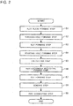
- Fig. 2 is a process chart indicating a method for manufacturing the heat exchanger 10 according to embodiment 1 of the present invention. As indicated in Fig. 2 , the method for manufacturing the heat exchanger 10 includes the following steps.
- step S1 as a flat plate forming step, a plate-shaped aluminum roll is extended to form an aluminum flat plate corresponding to a single fin 1.
- step S2 as a through-hole forming step, through holes 1a are formed in the aluminum flat plate corresponding to the single fin 1, and fin collars (not illustrated) are formed, the through holes 1a being provided to allow the heat transfer tubes 2 to be passed therethrough.
- step S3 as a slit forming step, slits (not illustrated) are formed in the aluminum flat plate corresponding to the single fin 1 by press working.
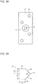
- Fig. 3A is a schematic diagram illustrating a fin prototype 11 according to embodiment 1 of the present invention.
- Fig. 3B is an enlarged schematic view of a portion A in Fig. 3A illustrating a starting hole 4 formed in the fin prototype 11 according to embodiment 1 of the present invention.
- step S4 in the starting hole forming step, a starting hole 4 is punched out in the aluminum flat plate corresponding to the single fin 1, thereby forming a fin prototype 11.
- a starting hole 4 is provided between adjacent through holes 1a.
- the starting hole 4 serves as the starting point of bending of the fin 1 and has a vertex portion 4a which has a minor angle ⁇ at a bending portion 3 close to the rear edge of the fin 1, which is located on the right side as seen in the figure.
- the following description contains descriptions in which the fin prototype 11 is referred to as the fin 1 in order that the fin prototype 11 be simply described.
- the starting hole 4 is formed to serve as the starting point of bending of the fin 1, and have a vertex portion 4a at the bending portion 3 which is close to the rear edge of the fin 1.
- the starting hole 4 has boundaries 4b and 4c that form the minor angle ⁇ in the direction from the vertex portion 4a toward the front edge of the fin 1.
- the starting hole 4 has a displacement allowable width 8 which is set to allow displacement of cuts 5 in the longitudinal direction of the fin 1 which is perpendicular to a direction along the short side of the fin 1, which is the extending direction of the cut 5. Also, the starting hole 4 has a depth-variation allowable width 9 which is set to allow variation between the depths of cuts 5, that is, the lengths thereof in the direction along the short side of the fin 1, that is the extending direction of the cut 5.
- the starting hole 4 has a boundary 4d which is opposite to the vertex portion 4a and the bending portion 3 of the fin 1, such the boundary 4d is provided in a straight line perpendicular to the extending direction of the cut 5.
- the straight line of the boundary 4d has the displacement allowable width 8.
- the starting hole 4 have boundaries 4e and 4f which connect both ends of the boundary 4d having the displacement allowable width 8 and front ends of the boundaries 4b and 4c, such that the boundaries 4e and 4f are provided in straight lines along the extending direction of the cut 5.
- the straight lines of the boundaries 4e and 4f have the depth-variation allowable width 9.
- the starting hole 4 is a hole surrounded by the boundaries 4b and 4c; which respectively extend obliquely upward and obliquely downward from the vertex portion 4a located close to the rear edge of the fin 1 toward the front edge of the fin 1 so as to form the minor angle ⁇ which is smaller than 180 degrees; the boundaries 4e and 4f provided in upper and lower straight lines, respectively, which extend in the direction along the short side of the fin 1 by the displacement allowable width 8 from the front ends of the boundaries 4b and 4c extending obliquely upward and obliquely downward; and the boundary 4d, which connects the upper and lower boundaries 4e and 4f and is provided in a straight line extending in the longitudinal direction of the fin 1.
- the starting hole 4 is formed in the shape of, for example, a pentagon similar to a home base. It should be noted that the starting hole 4 can be formed in another shape which varies in accordance with the arrangement of the plurality of through holes 1a formed in the fin 1.
- step S5 as a fin cutting step, the aluminum flat plate of the fin prototype 11 is cut to provide fins 1.
- step S6 as a heat-exchanger prototype forming step, a plurality of fins 1 are arranged, and heat transfer tubes 2 are passed through the through holes 1a, and are then expanded and subjected to caulking to form a heat-exchanger prototype 20. That is, in the heat-exchanger prototype forming step, a heat-exchanger prototype 20 in which the heat transfer tubes 2 are fixed to the plurality of fins 1 is formed.
- Fig. 4 is an explanatory view illustrating a state where the heat transfer tube 2 is fixed to the fin 1 in the heat-exchanger prototype 20 in embodiment 1 of the present invention.
- the heat transfer tube 2 is inserted into the through hole 1a of the fin 1, expanded and subjected to caulking. Thereby, the expanded heat transfer tube 2 comes into contact with a portion of the fin 1 that becomes a fin collar, and the fin 1 and the heat transfer tube 2 are fixed to each other.
- Fig. 5 is a schematic view illustrating a state in which a cut 5 is made in the heat-exchanger prototype 20 in embodiment 1 of the present invention.
- a blade is passed through the plurality of fins 1 of the heat-exchanger prototype 20 to make cuts 5 in all the fins 1. That is, in the cut making step, cuts 5 are made in the plurality of fins 1 of the heat-exchanger prototype 20 such that each of the cuts 5 connects the boundary 4d of an associated one of the fins 1, that is located opposite to the vertex portion 4a of an associated one of starting holes 4 formed through the fins 1, and the front edge of the associated fin 1, which is located on the left side as seen in the figure.
- the cuts 5 extend in the direction along the short side of each of the fins 1.
- the cuts 5 may be made to extend in an oblique direction, not the direction along the short side of each of the fins 1.
- each of the starting holes 4 is formed to have the displacement allowable width 8 in the longitudinal direction of the fin 1. Therefore, even if the positions of the cuts 5 made in the cut making step varies in the longitudinal direction of the fin 1, that is, a vertical direction as illustrated in the figure, it does not cause production of defectives, and the yield of produced heat exchangers can thus be improved.
- each of the starting holes 4 has the depth-variation allowable width 9 in the direction along the short side of the fin 1. Therefore, even if the lengths of the cuts 5 made in the cut making step vary in the direction along the short side of the fin 1, that is, each of them is too short or too long leftwards or rightwards in the direction along the short side of the fin 1, it does not cause production of defectives, and the yield of produced heat exchangers can thus be improved.
- step S8 as illustrated in Fig. 1 , as a bending step, the fin 1 in which the cut 5 is made is bent at the vertex portion 4a of the starting hole 4, by opening the cut 5 from the starting hole 4.
- the heat-exchanger prototype 20 is bent. At this time, the position of the above bending is determined with respect to the vertex portion 4a which corresponds to the vertex of the boundaries 4b and 4c which form the minor angle ⁇ at the rear edge side end of the starting hole 4, and the bending can be stably performed because of the provision of the vertex portion 4a. Therefore, the heat exchanger 10 can be formed in dimension with a high accuracy.
- step S9 as a pipe connecting step, pipes (not illustrated) are connected and brazed to the heat transfer tubes 2 of the heat exchanger 10.
- Fig. 6 is a diagram indicating the relationship between the thickness of the fin 1 and the bending strength of the fin 1 in embodiment 1 of the present invention.
- the fins 1 are each formed to have a thickness which falls within the range of 90 ⁇ m to 110 ⁇ m. It should be noted that the smaller the thickness of the fin 1, the lower the strength of the fin 1, and the more easily the fin 1 are broken when the fin 1 is bent. As illustrated in Fig. 5 , the fin 1 is formed to include the starting hole 4, and thus even if the formed fin 1 has a thickness of 90 ⁇ m, it can be bent. Furthermore, the thickness of the fin 1 is 110 ⁇ m or less. It thus does not cause a problem that the fin 1 is too thick, the fin strength is too high, and the fin 1 cannot be bent.
- Fig. 7 is a diagram indicating the range of the outer diameter of the heat transfer tubes 2 in embodiment 1 of the present invention.
- each of the heat transfer tubes 2 is made to have a smaller diameter.
- each of the heat transfer tubes 2 is set to fall within the range of 3.5 mm to 7.0 mm in order to improve the performance.
- each heat transfer tube 2 is 3.5 mm or more. It should be noted that in the case where each heat transfer tube 2 is made to have a smaller diameter, the area of each heat transfer tube 2 is decreased. Therefore, in order to secure an appropriate area of each heat transfer tube 2, it is necessary to reduce the pitch of adjacent heat transfer tubes 2 and the width of each of the slits which are formed to extend in the longitudinal direction of the fins 1. Therefore, in order to secure an appropriate area of the slits, the number of slits formed to be raised in the direction along the short side of each fink 1 is increased.
- the slits formed to be raised at the time of bending the fins 1 are not deformed.
- the degree of freedom of the position where the slits formed in the fin 1 are raised can be improved.
- the outer diameters of the heat transfer tubes 2 are 7.0 mm or less. It is therefore possible to reduce deterioration of heat transfer between the fins 1 and the refrigerant in the heat transfer tubes 2, which would occur if the heat transfer tubes 2 were made to have a great diameter, and the efficiency of heat transfer between the fins 1 and the refrigerant in the heat transfer tubes 2 can be improved.
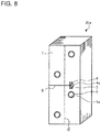
- Fig. 8 is a schematic diagram illustrating a state in which a cut 5 is made in a heat-exchanger prototype 20a in modification 1 of embodiment 1 of the present invention.
- Fig. 9 is a schematic diagram illustrating a heat exchanger 10a according to modification 1 of embodiment 1 of the present invention. The difference between modification 1 and embodiment 1 will be described with reference to Figs. 8 and 9 .
- a starting hole 4 and a cut 5 are made in each fin 1.
- the starting hole 4 is located on a rear side of the fin 1 where the bending portion 3 is located, with respect to a center line C of the fin 1 which is perpendicular to the direction along the short side of the fin 1, that is, a direction in which an extension of the cut 5 extends to pass through the vertex portion 4a.
- a bending width of the bending portion 3 is small, and the bending of the fins 1 can be performed with a high accuracy.
- the amount of deformation of the fin 1 at the bending portion 3 is reduced, and it is therefore possible to reduce dripping of dew from the bending portion 3 when the heat exchanger 10a is in operation.
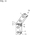
- Fig. 10 is a schematic diagram illustrating a state in which a cut 5 is made in a heat-exchanger prototype 20b in modification 2 of embodiment 1 of the present invention.
- Fig. 11 is a schematic diagram illustrating a heat exchanger 10b according to modification 2 of embodiment 1 of the present invention. The difference between modification 2 and embodiment 1 will be described with reference to Figs. 10 and 11 .
- the heat transfer tubes 2 are arranged in line in the longitudinal direction of the fins 1, which is perpendicular to the direction along the short side of each of the fins 1, that is, the extending direction of the cut 5.
- the fin strength is lowered, and the fins 1 are thus easily broken when they are bent.
- the starting hole 4 and the cuts 5 are made, even if the heat transfer tubes 2 are arranged in line in the longitudinal direction of the fins 1 which is perpendicular to the direction along the short sides of the fins 1, that is, the extending direction of the cut 5, the fins 1 can be bent without being broken.
- the heat exchangers 10, 10a and 10b each include a plurality of plate-shaped fins 1 arranged at intervals.
- the heat exchangers 10, 10a and 10b include heat transfer tubes 2 which are inserted into the through holes 1a of the fins 1 in the direction perpendicular to the fins 1.
- the starting hole 4 is formed between adjacent through holes 1a, serves as the start point of bending of the fin 1, and has the vertex portion 4a at the bending portion 3 close to the rear edge of the fin 1, which is located on the right side as seen in the figure.
- each fin 1 the cut 5 is made to connect the boundary 4d, which is located opposite to the vertex portion 4a of the starting hole 4, and the front edge of the fin 1, which is located on the left side as seen in the figure.
- the fin 1 is shaped such that it is bent at the vertex portion 4a of the starting hole 4, by opening the cut 5 from the starting hole 4.
- the starting point at which each of the fins 1 is bent is determined with respect to the vertex portion 4a of the associated starting hole 4, and the fins 1 are stably bent. Therefore, the heat exchangers 10, 10a and 10b in which the fins 1 are bent are formed in dimension and angle with a high accuracy.
- each of the starting holes 4 has a displacement allowable width 8 which is set to allow displacement of the cuts 5 in the direction perpendicular to the extending direction of the cuts 5.
- the starting holes 4 each have a depth-variation allowable width 9 which is set to allow variation between the depths of cuts 5, that is, the lengths thereof in the extending direction of the cuts 5.
- each starting hole 4 is provided with the depth-variation allowable width 9, and even if variation between the depths of the cuts 5, that is, the lengths of the cuts 5 in the extending direction of the cuts 5, occurs when the cut 5 is made, the cuts 5 can be formed such that such variation is allowed. Therefore, even if the depths of formed cuts 5 vary, such variation is allowed. It is therefore possible to improve the yield of heat exchangers 10, 10a and 10b.
- the starting hole 4 in each of the fins 1, as a side of the region having the displacement allowable width 8 and the depth-variation allowable width 9, the starting hole 4 has the boundary 4d which is located opposite to the bending portion 3 of the fin 1 and the vertex portion 4a, and which is located in a straight line perpendicular to the extending direction of the cut 5 of the fin 1. Furthermore, as sides of the region having the displacement allowable width 8 and the depth-variation allowable width 9, the starting hole 4 has boundaries 4e and 4f which extend by the displacement allowable width 8, and which are located in straight lines extending along the extending direction of the cut 5.
- the starting hole 4 e has the boundaries 4d, 4e and 4f of the region having the displacement allowable width 8 and the depth-variation allowable width 9.
- the vertex portion 4a is located closer to the bending portion 3 than the center line C of the fin 1, which is perpendicular to the extending direction of the cut 5.
- the bending width of the bending portion 3 is small, and the bending of the fin 1 can be performed with a high accuracy.
- the amount of deformation of the fin 1 at the bending portion 3 is small, as a result of which it is possible to reduce dripping of dew from the bending portion 3 when the heat exchanger 10a is in operation.
- the fins 1 are each formed to have a thickness which falls within the range of 90 ⁇ m to 110 ⁇ m.
- the thickness of each of the fins 1 is 90 ⁇ m or more. It should be noted that the smaller the thickness of each fin 1, the lower the strength thereof, and the more easily each fin 1 is broken when it is bent. However, since the thickness of each of the fins 1 is 90 ⁇ m or more, the fins 1 can be bent without being broken. Further, since the thickness of each of the fins 1 is 110 ⁇ m or less, it does not cause a problem in which the fins 1 are too thick, their strength is too strong, and the fins 1 cannot be bent.
- the heat transfer tubes 2 are arranged in line in a direction perpendicular to the extending direction of the cuts 5.
- the heat transfer tubes 2 are arranged in line in a direction perpendicular to the extending direction of the cuts.
- the strengths of the fins 1 are lowered, and the fins 1 are thus easily broken when the fins 1 are bent.
- the starting holes 4 and the cuts 5 are formed, as a result of which though the heat transfer tubes 2 are arranged in line in a direction perpendicular to the extending direction of the cuts 5, the fins 1 can be bent without being broken.
- the heat exchanger tubes 2 have an outer diameter which falls within the range of 3.5 mm to 7.0 mm.
- the outer diameter of the heat transfer tubes 2 is 3.5 mm or more. It should be noted that the area of the heat transfer tubes decreases as the diameter of the heat transfer tubes 2 decreases. Therefore, in order to secure an appropriate area of the heat transfer tubes, it is necessary to reduce the interval between adjacent ones of the heat transfer tubes 2. If it is reduced, the widths of the slits formed in the longitudinal direction of each fin 1 are also reduced. Therefore, in order to secure an appropriate slit area, the number of slits formed to be raised in the direction along the short side of the fin 1 is increased.
- the slits formed to be raised are not deformed at the time of bending the fin 1.
- the position where the slits formed in the fin 1 are raised has a higher degree of flexibility.
- the outer diameter of each of the heat transfer tubes 2 is 7.0 mm or less. Therefore, deterioration of heat transfer between the fin 1 and the refrigerant in the heat transfer tubes 2, which would occur if they were made to have a large diameter, can be reduced, and the efficiency of heat transfer between the fins 1 and the refrigerant in the heat transfer tubes 2 can be improved.
- the heat exchangers 10, 10a and 10b each include a plurality of plate-shaped fins 1 arranged at intervals.
- the heat exchangers 10, 10a and 10b each include heat transfer tubes 2 which are inserted into the through holes 1a of the fins 1 in the direction perpendicular to the fins 1.
- a method for manufacturing such heat exchanger 10, 10a or 10b includes the following steps.
- the method for manufacturing the heat exchanger 10, 10a or 10b includes a starting hole forming step (step S4) of forming, in each of fins 1, a starting hole 4 between adjacent through holes 1a, the starting hole 4 serving as the start point of bending of the fin 1, and having a vertex portion 4a which has a minor angle ⁇ at a bending portion 3 close to a rear edge of the fin 1, which is located on the right side as seen in the figure.
- the method for manufacturing the heat exchanger 10, 10a or 10b includes a heat-exchanger prototype forming step (step S 6) of forming a heat-exchanger prototype 20, 20a or 20b in which the heat transfer tubes 2 are fixed to the plurality of fins 1.
- the method for manufacturing the heat exchanger 1, 10a or 10b includes a cut making step (step S7) of making a cut 5 in the fins 1 of the heat-exchanger prototype 20, 20a or 20b, the cut 5 connecting a boundary 4d which is located opposite to the vertex portion 4a of the starting hole 4 and a front edge of the fin 1, which is located on the left side as seen in the figure.
- the method for manufacturing the heat exchanger 10, 10a or 10b includes a bending step (step S8) of bending each of the fins 1 in which the cut 5 is made, at the vertex portion 4a of the starting hole 4, by opening the cut 5 from the starting hole.
- the position of the starting point of bending of the fins 1 is determined with respect to the vertex portion 4a of the starting hole 4, and the fins 1 are stably bent. Therefore, the heat exchangers 10, 10a and 10b in which the fins 1 are bent are formed in dimension and angle with a high accuracy.
- the cut making step (step S7) is subsequent to the heat-exchanger prototype forming step (step S6) of forming the heat-exchanger prototype 20, 20a or 20b. It is therefore possible to prevent deformation of the fins at the time of manufacturing them, which would occur since their strength would be lowered by cuts if each of the fins is subjected to press-processing after the cut is made in each fin, or if the heat transfer tubes are fixed to the fins by caulking to form a heat-exchange prototype after the cut is made in each fin.
- cuts 5 are made in the fins 1 all at once. Thereby, the heat exchangers 10, 10a and 10b can be more easily manufactured, thus improving the manufacturing efficiency.
- Fig. 12 is a schematic configuration diagram illustrating an air-conditioning apparatus 100 according to embodiment 2 of the present invention.
- the flow of refrigerant during the cooling operation is indicated by solid arrows
- the flow of refrigerant during the heating operation is indicated by dotted arrows.
- the air-conditioning apparatus 100 includes a compressor 101, a four-way valve 102, a heat-source-side heat exchanger 103, an expansion device 104 and a load-side heat exchanger 105.
- the air-conditioning apparatus 100 includes a heat-source-side fan 106 which sends air to the heat-source-side heat exchanger 103 and a load-side fan 107 which sends air to the load-side heat exchanger 105.
- the air-conditioning apparatus 100 includes pipes 108 and 109 which connect the indoor unit and the outdoor unit.
- the air-conditioning apparatus 100 includes controllers 110 and 111 which control various movable components of the air-conditioning apparatus 100.
- the compressor 101, the four-way valve 102, the heat-source-side heat exchanger 103, the expansion device 104 and the load-side heat exchanger 105 are connected by refrigerant pipes, whereby a refrigerant cycle circuit is formed.
- the controllers 110 and 111 are connected to, for example, the compressor 101, the four-way valve 102, the expansion device 104, the heat-source-side fan 106, the load-side fan 107 and various sensors by communication lines.
- the controllers 110 and 111 perform switching between flow passages of the four-way valve 102, thereby switching the operation to be applied, between the cooling operation and the heating operation.
- the heat-source-side heat exchanger 103 functions as a condenser during the cooling operation, and functions as an evaporator during the heating operation.
- the load-side heat exchanger 105 functions as an evaporator during the cooling operation, and functions as a condenser during the heating operation.
- High-pressure and high-temperature gas refrigerant discharged from the compressor 101 flows into the heat-source-side heat exchanger 103 via the four-way valve 102.
- the refrigerant having flowed into the heat-source-side heat exchanger 103 is condensed by heat exchange with outdoor air sent by the heat-source-side fan 106 to change into high-pressure liquid refrigerant, and then flows out of the heat-source-side heat exchanger 103.
- the high pressure liquid refrigerant having flowed out of the heat-source-side heat exchanger 103 flows into the expansion device 104, and is changed into low-pressure two-phase gas-liquid refrigerant.
- the low-pressure two-phase gas-liquid refrigerant flows into the load-side heat exchanger 105, is evaporated by heat exchange with indoor air sent by the load-side fan 107 to change into low-pressure gas refrigerant, and then flows out of the load-side heat exchanger 105.
- the low-pressure gas refrigerant having flowed out of the load-side heat exchanger 105 is sucked into the compressor 101 via the four-way valve 102.
- High-pressure and high-temperature gas refrigerant discharged from the compressor 101 flows into the load-side heat exchanger 105 via the four-way valve 102.
- the refrigerant having flowed into the load-side heat exchanger 105 is condensed by heat exchange with indoor air sent by the load-side fan 107 to change into high-pressure liquid refrigerant, and then flows out of the load-side heat exchanger 105.
- the high-pressure liquid refrigerant having flowed out of the load-side heat exchanger 105 flows into the expansion device 104, and is changed into low-pressure two-phase gas-liquid refrigerant.
- the low-pressure two-phase gas-liquid refrigerant having flowed out of the expansion device 104 flows into the heat-source-side heat exchanger 103, is evaporated by heat exchange with outdoor air sent by the heat-source-side fan 106 to change into low-pressure gas refrigerant, and then flows out of the heat-source-side heat exchanger 103.
- the low pressure gas state refrigerant having flowed out of the heat-source-side heat exchanger 103 is sucked into the compressor 101 via the four-way valve 102.
- each of the heat exchanger 10, 10a and 10b according to embodiment 1 as the load-side heat exchanger 105, it is possible to obtain the following advantages: the dimensions and angle of the heat exchanger are accurate; and a high-performance air-conditioning apparatus 100 can be obtained.
- the air-conditioning apparatus 100 is described above as an example of a refrigeration cycle apparatus.
- the present invention is not limited to this. Any refrigeration cycle apparatus can be used as the refrigeration cycle apparatus of the present invention as long as it uses the heat exchanger 10, 10a or 10b according to embodiment 1 as a condenser or an evaporator.
- the air-conditioning apparatus 100 includes a refrigerant cycle circuit in which the compressor 101, the condenser, the expansion device 104 and the evaporator are sequentially connected by pipes.
- the heat exchangers 10, 10a and 10b according to embodiment 1 are each used as the load-side heat exchanger 105 functioning as a condenser or an evaporator.
- the heat exchangers 10, 10a and 10b which are formed and bent in angle and dimension with a high accuracy are each used as the condenser or the evaporator. As a result, the yield of products can be improved. In addition, a high-performance air-conditioning apparatus 100 can be provided.
Landscapes
- Engineering & Computer Science (AREA)
- Mechanical Engineering (AREA)
- Physics & Mathematics (AREA)
- Thermal Sciences (AREA)
- General Engineering & Computer Science (AREA)
- Geometry (AREA)
- Heat-Exchange Devices With Radiators And Conduit Assemblies (AREA)
- Air Filters, Heat-Exchange Apparatuses, And Housings Of Air-Conditioning Units (AREA)
- Punching Or Piercing (AREA)
Abstract
Description
- The present invention relates to a heat exchanger provided with bent fins, a refrigeration cycle apparatus, and a method for manufacturing the heat exchanger.
- In conventional heat exchangers for use in air-conditioning apparatuses, especially, for use in indoor units of wall-mounted air-conditioning apparatuses, fins are bent because they are provided in a limited inner space of a housing.
- As a method for bending the fins of the heat exchanger,
Patent Literature 1 discloses a technique. In the technique ofPatent Literature 1, cuts or notches are formed in fins included in a heat exchanger, to thereby bend the fins. - Patent Literature 1: Japanese Unexamined Patent Application Publication No.
5-164347 - However, in the technique of
Patent Literature 1, since tip portions of the cuts are rectangular, bending positions of the fins are not stable when the fins are bent in the process of manufacturing a heat exchanger. Thus, after bending of the fins, the accuracy of the dimensions and angle of the heat exchanger is low. Therefore, it is hard to produce heat exchangers with a high accuracy in dimension and angle, after bending of fins. - The present invention has been made to solve the above problems, and it is an object of the present invention to provide a heat exchanger provided with bent fins, that is produced with a high accuracy in dimension and angle, a refrigeration cycle apparatus, and a method for manufacturing the heat exchanger.
- A heat exchanger according to an embodiment of the present invention includes: a plurality of plate-shaped fins disposed at intervals; and a plurality of heat transfer tubes inserted in through holes of the fins in a direction perpendicular to the fins, the fins each including a starting hole which is formed therethrough and located adjacent ones of the through holes of the each fin to serve as a start point of bending of the each fin and have a vertex portion at a bending portion of the each fin which is closer to an edge thereof, the each fin including a cut which is made to connect an other edge of the each fin and a side of the starting hole which is located opposite to the vertex portion of the starting hole, the each fin being bent at the vertex portion of the starting hole by opening the cut from the starting hole.
- A refrigeration cycle apparatus according to another embodiment of the present invention includes a refrigerant cycle circuit in which a compressor, a condenser, an expansion device and an evaporator are sequentially connected by pipes. The above heat exchanger is used as the condenser or the evaporator.
- A method for manufacturing a heat exchanger, according to still another embodiment of the present invention, the heat exchanger including a plurality of plate-shaped fins disposed at intervals, and a plurality of heat transfer tubes disposed to be inserted into through holes of the fins in a direction perpendicular to the fins, includes: a starting hole forming step of forming a starting hole between adjacent one of the through holes of each of the fins, the starting hole serving as a start point of bending of the each fin and having a vertex portion which has a minor angle at a bending portion of the each fin which is close to an edge thereof; a heat-exchanger prototype forming step of forming a heat-exchanger prototype in which the heat transfer tubes are fixed to the fins; a cut making step of making a cut in each of the fins of the heat-exchanger prototype, the cut connecting an other edge of the each fin and a side of the starting hole which is located opposite to the vertex portion of the starting hole; and a bending step of bending the each fin in which the cut is made, at the vertex portion of the starting hole, by opening the cut from the starting hole.
- According to the present invention, the fins are each bent at the vertex portion of the associated starting hole by opening the associated cut from the starting hole. For this reason, the position of the starting point at which each fin are bent is determined with respect to the vertex portion of the starting hole, and the fins are stably bent. Therefore, the heat exchanger provided with bent fins is formed in dimension and angle with a high accuracy.
-
-
Fig. 1 is a schematic diagram illustrating a heat exchanger according toembodiment 1 of the present invention. -
Fig. 2 is a process chart indicating a method for manufacturing the heat exchanger according toembodiment 1 of the present invention. -
Fig. 3A is a schematic view illustrating a fin prototype according toembodiment 1 of the present invention. -
Fig. 3B is an enlarged schematic view of a portion A inFig. 3A illustrating a starting hole of the fin prototype according toembodiment 1 of the present invention. -
Fig. 4 is an explanatory view illustrating a state in which a heat transfer tube is fixed to a fin in the heat-exchanger prototype according toembodiment 1 of the present invention. -
Fig. 5 is a schematic view showing a state in which a cut is made in the heat-exchanger prototype according toembodiment 1 of the present invention. -
Fig. 6 is a view indicating a relationship between the thickness of the fin and the bending strength of the fin inembodiment 1 of the present invention. -
Fig. 7 is a view indicating a range of an outside diameter of a heat transfer tube inembodiment 1 of the present invention. -
Fig. 8 is a schematic view showing a state in which a cut is made in a heat-exchanger prototype according to a first modification ofembodiment 1 of the present invention. -
Fig. 9 is a schematic diagram showing a heat exchanger according to a first modification ofembodiment 1 of the present invention. -
Fig. 10 is a schematic view showing a state in which a cut is made in a heat-exchanger prototype according to a second modification ofembodiment 1 of the present invention. -
Fig. 11 is a schematic diagram showing a heat exchanger according to a second modification ofembodiment 1 of the present invention. -
Fig. 12 is a schematic configuration diagram illustrating an air conditioner according toembodiment 2 of the present invention. - Embodiments of the present invention will be described as appropriate with reference to the drawings. In the following drawings including
Fig. 1 , the relationship in size between the components may differ from that between actual ones. In each figure in the following drawings including inFig. 1 , elements which are same as or equivalent to those illustrated in a previous figure are denoted by the same signs. The same is true of the full text of the specification. Furthermore, the forms of components described in the full text of the specification are merely examples, and the forms are not limited to those described in the text. -
Fig. 1 is a schematic diagram showing aheat exchanger 10 according toembodiment 1 of the present invention. - The
heat exchanger 10 as illustrated inFig. 1 includes a plurality of plate-shaped fins 1 arranged in parallel at intervals. Theheat exchanger 10 includesheat transfer tubes 2 which are inserted into throughholes 1a of thefins 1 in a direction perpendicular to the plurality offins 1. - The
fins 1 are each formed of a plate material which is rectangular and bent. In each of thefins 1, asingle starting hole 4 is formed between adjacent throughholes 1a. Thestarting hole 4 serves as a start point of bending of eachfin 1, and has avertex portion 4a at abending portion 3 close to a rear edge of eachfin 1, which is the right one of edge sides thereof as seen in the figure. Thestarting hole 4 is provided at a position where eachfin 1 is bent. Thestarting hole 4 is formed through eachfin 1. Thestarting hole 4 is located in such a way as to avoid the adjacent throughholes 1a, and is also continuous with acut 5. Thevertex portion 4a of thestarting hole 4 is the vertex ofboundaries starting hole 4. - In each
fin 1, thecut 5 is made to connect aboundary 4d which is located opposite to thevertex portion 4a of thestarting hole 4, and a front edge of eachfin 1, which is located on the left side as seen in the figure. Thecut 5 of thefin 1 gradually broadens from thestarting hole 4 toward the front edge of thefin 1. - The
fin 1 is bent at thevertex portion 4a of thestarting hole 4 by opening and widening thecut 5 from thestarting hole 4. To be more specific, in theheat exchanger 10, anupper half 7 is inclined obliquely rearwards with respect to alower half 6. -
Fig. 2 is a process chart indicating a method for manufacturing theheat exchanger 10 according toembodiment 1 of the present invention. As indicated inFig. 2 , the method for manufacturing theheat exchanger 10 includes the following steps. - In step S1, as a flat plate forming step, a plate-shaped aluminum roll is extended to form an aluminum flat plate corresponding to a
single fin 1. - In step S2, as a through-hole forming step, through
holes 1a are formed in the aluminum flat plate corresponding to thesingle fin 1, and fin collars (not illustrated) are formed, the throughholes 1a being provided to allow theheat transfer tubes 2 to be passed therethrough. - In step S3, as a slit forming step, slits (not illustrated) are formed in the aluminum flat plate corresponding to the
single fin 1 by press working. -
Fig. 3A is a schematic diagram illustrating afin prototype 11 according toembodiment 1 of the present invention.Fig. 3B is an enlarged schematic view of a portion A inFig. 3A illustrating astarting hole 4 formed in thefin prototype 11 according toembodiment 1 of the present invention. - In step S4, as illustrated in
Fig. 3A , in the starting hole forming step, astarting hole 4 is punched out in the aluminum flat plate corresponding to thesingle fin 1, thereby forming afin prototype 11. To be more specific, in the starting hole forming step, in thesingle fin 1 or the aluminum flat plate corresponding to thesingle fin 1, astarting hole 4 is provided between adjacent throughholes 1a. Thestarting hole 4 serves as the starting point of bending of thefin 1 and has avertex portion 4a which has a minor angle α at a bendingportion 3 close to the rear edge of thefin 1, which is located on the right side as seen in the figure. The following description contains descriptions in which thefin prototype 11 is referred to as thefin 1 in order that thefin prototype 11 be simply described. - As illustrated in
Figs. 3A and 3B , between adjacent throughholes 1a, thestarting hole 4 is formed to serve as the starting point of bending of thefin 1, and have avertex portion 4a at the bendingportion 3 which is close to the rear edge of thefin 1. Thestarting hole 4 hasboundaries vertex portion 4a toward the front edge of thefin 1. - The
starting hole 4 has a displacementallowable width 8 which is set to allow displacement ofcuts 5 in the longitudinal direction of thefin 1 which is perpendicular to a direction along the short side of thefin 1, which is the extending direction of thecut 5. Also, thestarting hole 4 has a depth-variationallowable width 9 which is set to allow variation between the depths ofcuts 5, that is, the lengths thereof in the direction along the short side of thefin 1, that is the extending direction of thecut 5. - As a side of a region having the displacement
allowable width 8 and the depth-variationallowable width 9, thestarting hole 4 has aboundary 4d which is opposite to thevertex portion 4a and the bendingportion 3 of thefin 1, such theboundary 4d is provided in a straight line perpendicular to the extending direction of thecut 5. The straight line of theboundary 4d has the displacementallowable width 8. - Furthermore, as sides of the region having the displacement
allowable width 8 and the depth-variationallowable width 9, thestarting hole 4 haveboundaries boundary 4d having the displacementallowable width 8 and front ends of theboundaries boundaries cut 5. The straight lines of theboundaries allowable width 9. - That is, the
starting hole 4 is a hole surrounded by theboundaries vertex portion 4a located close to the rear edge of thefin 1 toward the front edge of thefin 1 so as to form the minor angle α which is smaller than 180 degrees; theboundaries fin 1 by the displacementallowable width 8 from the front ends of theboundaries boundary 4d, which connects the upper andlower boundaries fin 1. - The
starting hole 4 is formed in the shape of, for example, a pentagon similar to a home base. It should be noted that thestarting hole 4 can be formed in another shape which varies in accordance with the arrangement of the plurality of throughholes 1a formed in thefin 1. - In step S5, as a fin cutting step, the aluminum flat plate of the
fin prototype 11 is cut to providefins 1. - In step S6, as a heat-exchanger prototype forming step, a plurality of
fins 1 are arranged, andheat transfer tubes 2 are passed through the throughholes 1a, and are then expanded and subjected to caulking to form a heat-exchanger prototype 20. That is, in the heat-exchanger prototype forming step, a heat-exchanger prototype 20 in which theheat transfer tubes 2 are fixed to the plurality offins 1 is formed. -
Fig. 4 is an explanatory view illustrating a state where theheat transfer tube 2 is fixed to thefin 1 in the heat-exchanger prototype 20 inembodiment 1 of the present invention. - As illustrated in
Fig. 4 , theheat transfer tube 2 is inserted into the throughhole 1a of thefin 1, expanded and subjected to caulking. Thereby, the expandedheat transfer tube 2 comes into contact with a portion of thefin 1 that becomes a fin collar, and thefin 1 and theheat transfer tube 2 are fixed to each other. -
Fig. 5 is a schematic view illustrating a state in which acut 5 is made in the heat-exchanger prototype 20 inembodiment 1 of the present invention. - In step S7, as illustrated in
Fig. 5 , as a cut making step, a blade is passed through the plurality offins 1 of the heat-exchanger prototype 20 to makecuts 5 in all thefins 1. That is, in the cut making step, cuts 5 are made in the plurality offins 1 of the heat-exchanger prototype 20 such that each of thecuts 5 connects theboundary 4d of an associated one of thefins 1, that is located opposite to thevertex portion 4a of an associated one of startingholes 4 formed through thefins 1, and the front edge of the associatedfin 1, which is located on the left side as seen in the figure. Thecuts 5 extend in the direction along the short side of each of thefins 1. Thecuts 5 may be made to extend in an oblique direction, not the direction along the short side of each of thefins 1. - It should be noted that in the case of
heat exchangers 10 are mass-produced, the positions ofcuts 5 made in the cut making step corresponding to step S7 vary. - However, each of the starting holes 4 is formed to have the displacement
allowable width 8 in the longitudinal direction of thefin 1. Therefore, even if the positions of thecuts 5 made in the cut making step varies in the longitudinal direction of thefin 1, that is, a vertical direction as illustrated in the figure, it does not cause production of defectives, and the yield of produced heat exchangers can thus be improved. - Also, each of the starting holes 4 has the depth-variation
allowable width 9 in the direction along the short side of thefin 1. Therefore, even if the lengths of thecuts 5 made in the cut making step vary in the direction along the short side of thefin 1, that is, each of them is too short or too long leftwards or rightwards in the direction along the short side of thefin 1, it does not cause production of defectives, and the yield of produced heat exchangers can thus be improved. - In step S8, as illustrated in
Fig. 1 , as a bending step, thefin 1 in which thecut 5 is made is bent at thevertex portion 4a of thestarting hole 4, by opening thecut 5 from thestarting hole 4. - By dividing the
fin 1 from thecut 5 into theupper half 7 and thelower half 6, the heat-exchanger prototype 20 is bent. At this time, the position of the above bending is determined with respect to thevertex portion 4a which corresponds to the vertex of theboundaries starting hole 4, and the bending can be stably performed because of the provision of thevertex portion 4a. Therefore, theheat exchanger 10 can be formed in dimension with a high accuracy. - In step S9, as a pipe connecting step, pipes (not illustrated) are connected and brazed to the
heat transfer tubes 2 of theheat exchanger 10. - As a result, the
heat exchanger 10 is completely produced. -
Fig. 6 is a diagram indicating the relationship between the thickness of thefin 1 and the bending strength of thefin 1 inembodiment 1 of the present invention. - The
fins 1 are each formed to have a thickness which falls within the range of 90 µm to 110 µm. It should be noted that the smaller the thickness of thefin 1, the lower the strength of thefin 1, and the more easily thefin 1 are broken when thefin 1 is bent. As illustrated inFig. 5 , thefin 1 is formed to include thestarting hole 4, and thus even if the formedfin 1 has a thickness of 90 µm, it can be bent. Furthermore, the thickness of thefin 1 is 110 µm or less. It thus does not cause a problem that thefin 1 is too thick, the fin strength is too high, and thefin 1 cannot be bent. -
Fig. 7 is a diagram indicating the range of the outer diameter of theheat transfer tubes 2 inembodiment 1 of the present invention. - In the
heat exchanger 10, in order to promote heat transfer, slits are formed to be raised between the throughholes 1a in each of thefins 1, and each of theheat transfer tubes 2 is made to have a smaller diameter. - As indicated in
Fig. 7 , the outer diameter of each of theheat transfer tubes 2 is set to fall within the range of 3.5 mm to 7.0 mm in order to improve the performance. - The outer diameter of each
heat transfer tube 2 is 3.5 mm or more. It should be noted that in the case where eachheat transfer tube 2 is made to have a smaller diameter, the area of eachheat transfer tube 2 is decreased. Therefore, in order to secure an appropriate area of eachheat transfer tube 2, it is necessary to reduce the pitch of adjacentheat transfer tubes 2 and the width of each of the slits which are formed to extend in the longitudinal direction of thefins 1. Therefore, in order to secure an appropriate area of the slits, the number of slits formed to be raised in the direction along the short side of eachfink 1 is increased. On the other hand, since the bending position of each of thefins 1 is determined with respect to thestarting hole 4 and thecut 5 during mass production of theheat exchanger 10, the slits formed to be raised at the time of bending thefins 1 are not deformed. Thus, the degree of freedom of the position where the slits formed in thefin 1 are raised can be improved. Furthermore, the outer diameters of theheat transfer tubes 2 are 7.0 mm or less. It is therefore possible to reduce deterioration of heat transfer between thefins 1 and the refrigerant in theheat transfer tubes 2, which would occur if theheat transfer tubes 2 were made to have a great diameter, and the efficiency of heat transfer between thefins 1 and the refrigerant in theheat transfer tubes 2 can be improved. -
Fig. 8 is a schematic diagram illustrating a state in which acut 5 is made in a heat-exchanger prototype 20a inmodification 1 ofembodiment 1 of the present invention.Fig. 9 is a schematic diagram illustrating aheat exchanger 10a according tomodification 1 ofembodiment 1 of the present invention. The difference betweenmodification 1 andembodiment 1 will be described with reference toFigs. 8 and9 . - As in
embodiment 1, astarting hole 4 and acut 5 are made in eachfin 1. As illustrated inFig. 8 , thestarting hole 4 is located on a rear side of thefin 1 where the bendingportion 3 is located, with respect to a center line C of thefin 1 which is perpendicular to the direction along the short side of thefin 1, that is, a direction in which an extension of thecut 5 extends to pass through thevertex portion 4a. - As illustrated in
Fig. 9 , since thevertex portion 4a of thestarting hole 4 is located on the rear side of thefin 1 with respect to the center line C of thefin 1 which is perpendicular to the direction along the short side of thefin 1, a bending width of the bendingportion 3 is small, and the bending of thefins 1 can be performed with a high accuracy. In addition, the amount of deformation of thefin 1 at the bendingportion 3 is reduced, and it is therefore possible to reduce dripping of dew from the bendingportion 3 when theheat exchanger 10a is in operation. -
Fig. 10 is a schematic diagram illustrating a state in which acut 5 is made in a heat-exchanger prototype 20b inmodification 2 ofembodiment 1 of the present invention.Fig. 11 is a schematic diagram illustrating aheat exchanger 10b according tomodification 2 ofembodiment 1 of the present invention. The difference betweenmodification 2 andembodiment 1 will be described with reference toFigs. 10 and11 . - Unlike
embodiment 1, theheat transfer tubes 2 are arranged in line in the longitudinal direction of thefins 1, which is perpendicular to the direction along the short side of each of thefins 1, that is, the extending direction of thecut 5. - In the case where the
heat transfer tubes 2 are arranged in line in the longitudinal direction of thefins 1, which is perpendicular to the direction along the short side of each of thefins 1, that is, the extending direction of thecuts 5, the fin strength is lowered, and thefins 1 are thus easily broken when they are bent. However, as inembodiment 1, since thestarting hole 4 and thecuts 5 are made, even if theheat transfer tubes 2 are arranged in line in the longitudinal direction of thefins 1 which is perpendicular to the direction along the short sides of thefins 1, that is, the extending direction of thecut 5, thefins 1 can be bent without being broken. - According to
embodiment 1 and the modifications thereof, theheat exchangers fins 1 arranged at intervals. Theheat exchangers heat transfer tubes 2 which are inserted into the throughholes 1a of thefins 1 in the direction perpendicular to thefins 1. In each of thefins 1, thestarting hole 4 is formed between adjacent throughholes 1a, serves as the start point of bending of thefin 1, and has thevertex portion 4a at the bendingportion 3 close to the rear edge of thefin 1, which is located on the right side as seen in the figure. In eachfin 1, thecut 5 is made to connect theboundary 4d, which is located opposite to thevertex portion 4a of thestarting hole 4, and the front edge of thefin 1, which is located on the left side as seen in the figure. Thefin 1 is shaped such that it is bent at thevertex portion 4a of thestarting hole 4, by opening thecut 5 from thestarting hole 4. - In this configuration, the starting point at which each of the
fins 1 is bent is determined with respect to thevertex portion 4a of the associated startinghole 4, and thefins 1 are stably bent. Therefore, theheat exchangers fins 1 are bent are formed in dimension and angle with a high accuracy. - According to
embodiment 1, each of the starting holes 4 has a displacementallowable width 8 which is set to allow displacement of thecuts 5 in the direction perpendicular to the extending direction of thecuts 5. - In this configuration, because of the displacement
allowable width 8 of thestarting hole 4, even if displacement ofcuts 5 occurs in the direction perpendicular to the extending direction of thecuts 5 when thecuts 5 are made, thecuts 5 can be formed such that their displacement is allowed. Therefore, even if the positions of madecuts 5 vary, such variation is allowed. It is therefore possible to improve the yield ofheat exchangers - According to
embodiment 1, the startingholes 4 each have a depth-variationallowable width 9 which is set to allow variation between the depths ofcuts 5, that is, the lengths thereof in the extending direction of thecuts 5. - In this configuration, each starting
hole 4 is provided with the depth-variationallowable width 9, and even if variation between the depths of thecuts 5, that is, the lengths of thecuts 5 in the extending direction of thecuts 5, occurs when thecut 5 is made, thecuts 5 can be formed such that such variation is allowed. Therefore, even if the depths of formedcuts 5 vary, such variation is allowed. It is therefore possible to improve the yield ofheat exchangers - According to
embodiment 1, in each of thefins 1, as a side of the region having the displacementallowable width 8 and the depth-variationallowable width 9, thestarting hole 4 has theboundary 4d which is located opposite to the bendingportion 3 of thefin 1 and thevertex portion 4a, and which is located in a straight line perpendicular to the extending direction of thecut 5 of thefin 1. Furthermore, as sides of the region having the displacementallowable width 8 and the depth-variationallowable width 9, thestarting hole 4 hasboundaries allowable width 8, and which are located in straight lines extending along the extending direction of thecut 5. - In this configuration, the
starting hole 4 e has theboundaries allowable width 8 and the depth-variationallowable width 9. Thus, even if such displacement and variation as described above occur whencuts 5 are made, thecuts 5 can be made such that the displacement and variation are allowed. Therefore, even if the positions and depths of the madecuts 5 vary, such variations can be allowed. It is therefore possible to improve the yield ofheat exchangers - According to
embodiment 1, thevertex portion 4a is located closer to the bendingportion 3 than the center line C of thefin 1, which is perpendicular to the extending direction of thecut 5. - In this configuration, the bending width of the bending
portion 3 is small, and the bending of thefin 1 can be performed with a high accuracy. In addition, the amount of deformation of thefin 1 at the bendingportion 3 is small, as a result of which it is possible to reduce dripping of dew from the bendingportion 3 when theheat exchanger 10a is in operation. - According to
embodiment 1, thefins 1 are each formed to have a thickness which falls within the range of 90 µm to 110 µm. - In this configuration, the thickness of each of the
fins 1 is 90 µm or more. It should be noted that the smaller the thickness of eachfin 1, the lower the strength thereof, and the more easily eachfin 1 is broken when it is bent. However, since the thickness of each of thefins 1 is 90 µm or more, thefins 1 can be bent without being broken. Further, since the thickness of each of thefins 1 is 110 µm or less, it does not cause a problem in which thefins 1 are too thick, their strength is too strong, and thefins 1 cannot be bent. - According to
embodiment 1, theheat transfer tubes 2 are arranged in line in a direction perpendicular to the extending direction of thecuts 5. - In this configuration, the
heat transfer tubes 2 are arranged in line in a direction perpendicular to the extending direction of the cuts. In the case where theheat transfer tubes 2 are arranged in line in a direction perpendicular to the extending direction of thecuts 5, the strengths of thefins 1 are lowered, and thefins 1 are thus easily broken when thefins 1 are bent. However, in the modification, the startingholes 4 and thecuts 5 are formed, as a result of which though theheat transfer tubes 2 are arranged in line in a direction perpendicular to the extending direction of thecuts 5, thefins 1 can be bent without being broken. - According to
embodiment 1, theheat exchanger tubes 2 have an outer diameter which falls within the range of 3.5 mm to 7.0 mm. - In this configuration, the outer diameter of the
heat transfer tubes 2 is 3.5 mm or more. It should be noted that the area of the heat transfer tubes decreases as the diameter of theheat transfer tubes 2 decreases. Therefore, in order to secure an appropriate area of the heat transfer tubes, it is necessary to reduce the interval between adjacent ones of theheat transfer tubes 2. If it is reduced, the widths of the slits formed in the longitudinal direction of eachfin 1 are also reduced. Therefore, in order to secure an appropriate slit area, the number of slits formed to be raised in the direction along the short side of thefin 1 is increased. On the other hand, since the bending position of thefin 1 is determined with respect to thestarting hole 4 and thecut 5 during mass production ofheat exchangers fin 1. Thus, the position where the slits formed in thefin 1 are raised has a higher degree of flexibility. Further, it should be noted that the outer diameter of each of theheat transfer tubes 2 is 7.0 mm or less. Therefore, deterioration of heat transfer between thefin 1 and the refrigerant in theheat transfer tubes 2, which would occur if they were made to have a large diameter, can be reduced, and the efficiency of heat transfer between thefins 1 and the refrigerant in theheat transfer tubes 2 can be improved. - According to
embodiment 1, theheat exchangers fins 1 arranged at intervals. Theheat exchangers heat transfer tubes 2 which are inserted into the throughholes 1a of thefins 1 in the direction perpendicular to thefins 1. A method for manufacturingsuch heat exchanger heat exchanger fins 1, astarting hole 4 between adjacent throughholes 1a, thestarting hole 4 serving as the start point of bending of thefin 1, and having avertex portion 4a which has a minor angle α at a bendingportion 3 close to a rear edge of thefin 1, which is located on the right side as seen in the figure. The method for manufacturing theheat exchanger exchanger prototype heat transfer tubes 2 are fixed to the plurality offins 1. The method for manufacturing theheat exchanger cut 5 in thefins 1 of the heat-exchanger prototype cut 5 connecting aboundary 4d which is located opposite to thevertex portion 4a of thestarting hole 4 and a front edge of thefin 1, which is located on the left side as seen in the figure. The method for manufacturing theheat exchanger fins 1 in which thecut 5 is made, at thevertex portion 4a of thestarting hole 4, by opening thecut 5 from the starting hole. - In the above configuration, the position of the starting point of bending of the
fins 1 is determined with respect to thevertex portion 4a of thestarting hole 4, and thefins 1 are stably bent. Therefore, theheat exchangers fins 1 are bent are formed in dimension and angle with a high accuracy. - Furthermore, in the above method, the cut making step (step S7) is subsequent to the heat-exchanger prototype forming step (step S6) of forming the heat-
exchanger prototype fins 1 all at once. Thereby, theheat exchangers -
Fig. 12 is a schematic configuration diagram illustrating an air-conditioning apparatus 100 according toembodiment 2 of the present invention. InFig. 12 , the flow of refrigerant during the cooling operation is indicated by solid arrows, and the flow of refrigerant during the heating operation is indicated by dotted arrows. - As illustrated in
Fig. 12 , the air-conditioning apparatus 100 includes acompressor 101, a four-way valve 102, a heat-source-side heat exchanger 103, anexpansion device 104 and a load-side heat exchanger 105. The air-conditioning apparatus 100 includes a heat-source-side fan 106 which sends air to the heat-source-side heat exchanger 103 and a load-side fan 107 which sends air to the load-side heat exchanger 105. The air-conditioning apparatus 100 includespipes conditioning apparatus 100 includescontrollers conditioning apparatus 100. - In the air-
conditioning apparatus 100, thecompressor 101, the four-way valve 102, the heat-source-side heat exchanger 103, theexpansion device 104 and the load-side heat exchanger 105 are connected by refrigerant pipes, whereby a refrigerant cycle circuit is formed. - The
controllers compressor 101, the four-way valve 102, theexpansion device 104, the heat-source-side fan 106, the load-side fan 107 and various sensors by communication lines. - The
controllers way valve 102, thereby switching the operation to be applied, between the cooling operation and the heating operation. The heat-source-side heat exchanger 103 functions as a condenser during the cooling operation, and functions as an evaporator during the heating operation. The load-side heat exchanger 105 functions as an evaporator during the cooling operation, and functions as a condenser during the heating operation. - High-pressure and high-temperature gas refrigerant discharged from the
compressor 101 flows into the heat-source-side heat exchanger 103 via the four-way valve 102. The refrigerant having flowed into the heat-source-side heat exchanger 103 is condensed by heat exchange with outdoor air sent by the heat-source-side fan 106 to change into high-pressure liquid refrigerant, and then flows out of the heat-source-side heat exchanger 103. The high pressure liquid refrigerant having flowed out of the heat-source-side heat exchanger 103 flows into theexpansion device 104, and is changed into low-pressure two-phase gas-liquid refrigerant. After theexpansion device 104, the low-pressure two-phase gas-liquid refrigerant flows into the load-side heat exchanger 105, is evaporated by heat exchange with indoor air sent by the load-side fan 107 to change into low-pressure gas refrigerant, and then flows out of the load-side heat exchanger 105. The low-pressure gas refrigerant having flowed out of the load-side heat exchanger 105 is sucked into thecompressor 101 via the four-way valve 102. - High-pressure and high-temperature gas refrigerant discharged from the
compressor 101 flows into the load-side heat exchanger 105 via the four-way valve 102. The refrigerant having flowed into the load-side heat exchanger 105 is condensed by heat exchange with indoor air sent by the load-side fan 107 to change into high-pressure liquid refrigerant, and then flows out of the load-side heat exchanger 105. The high-pressure liquid refrigerant having flowed out of the load-side heat exchanger 105 flows into theexpansion device 104, and is changed into low-pressure two-phase gas-liquid refrigerant. The low-pressure two-phase gas-liquid refrigerant having flowed out of theexpansion device 104 flows into the heat-source-side heat exchanger 103, is evaporated by heat exchange with outdoor air sent by the heat-source-side fan 106 to change into low-pressure gas refrigerant, and then flows out of the heat-source-side heat exchanger 103. The low pressure gas state refrigerant having flowed out of the heat-source-side heat exchanger 103 is sucked into thecompressor 101 via the four-way valve 102. - By using each of the
heat exchanger embodiment 1 as the load-side heat exchanger 105, it is possible to obtain the following advantages: the dimensions and angle of the heat exchanger are accurate; and a high-performance air-conditioning apparatus 100 can be obtained. - Witt respect to
embodiment 2, the air-conditioning apparatus 100 is described above as an example of a refrigeration cycle apparatus. The present invention is not limited to this. Any refrigeration cycle apparatus can be used as the refrigeration cycle apparatus of the present invention as long as it uses theheat exchanger embodiment 1 as a condenser or an evaporator. - According to
embodiment 2, the air-conditioning apparatus 100 includes a refrigerant cycle circuit in which thecompressor 101, the condenser, theexpansion device 104 and the evaporator are sequentially connected by pipes. Theheat exchangers embodiment 1 are each used as the load-side heat exchanger 105 functioning as a condenser or an evaporator. - In this configuration, the
heat exchangers conditioning apparatus 100 can be provided. Reference Signs List - 1
fin 1a throughhole 2heat transfer tube 3bending portion 4starting hole 4a vertex 4cportion 4b boundaryboundary 4dboundary 4e boundaryboundary 5 cut 6lower half 7upper half 8 displacementallowable width 9 depth-variationallowable width 10heat exchanger 10a heat exchanger 10b heat exchanger 11fin prototype 20 heat-exchanger prototype 20a heat-exchanger prototype 20b heat-exchanger prototype 100 air-conditioning apparatus 101compressor 102 four-way valve 103 heat-source-side heat exchanger 104expansion device 105 load-side heat exchanger 106 heat-source-side fan 107 load-side fan 108pipe 109pipe 110controller 111 controller
Claims (10)
- A heat exchanger comprising:a plurality of plate-shaped fins disposed at intervals; anda plurality of heat transfer tubes inserted in through holes of the fins in a direction perpendicular to the fins,the fins each including a starting hole which is formed therethrough and located adjacent ones of the through holes of the each fin to serve as a start point of bending of the each fin and have a vertex portion at a bending portion of the each fin which is closer to an edge thereof,the each fin including a cut which is made to connect an other edge of the each fin and a side of the starting hole which is located opposite to the vertex portion of the starting hole,the each fin being bent at the vertex portion of the starting hole by opening the cut from the starting hole.
- The heat exchanger of claim 1, wherein the starting hole has a displacement allowable width which is set to allow displacement of the cut in a direction perpendicular to an extending direction of the cut.
- The heat exchanger of claim 1 or 2, wherein the starting hole has a depth-variation allowable width which is set to allow variation between lengths of cuts of the fins in the extending direction of the cuts.
- The heat exchanger of claim 3, wherein the starting hole has, as sides of a region having both the displacement allowable width and the depth-variation allowable width, a boundary which is located opposite to the bending portion of the each fin and the vertex portion, and which is located in a straight line perpendicular to the extending direction of the cut, and boundaries which extend by the displacement allowable width, and which are located in straight lines extending in the extending direction of the cut.
- The heat exchanger of any one of claims 1 to 4, wherein the vertex portion is located closer to the bending portion than to a center line of the each fin which is perpendicular to the extending direction of the cut.
- The heat exchanger of any one of claims 1 to 5, wherein the fins are each formed to have a thickness which falls within a range of 90 µm to 110 µm.
- The heat exchanger of any one of claims 1 to 6, wherein the heat transfer tubes are arranged in line in a direction perpendicular to the extending direction of the cut.
- The heat exchanger of any one of claims 1 to 7, wherein the heat transfer tubes each have an outer diameter which falls within a range of 3.5 mm to 7.0 mm.
- A refrigeration cycle apparatus comprising a refrigerant cycle circuit in which a compressor, a condenser, an expansion device and an evaporator are sequentially connected by pipes,
the heat exchanger of any one of claims 1 to 8 being used as the condenser or the evaporator. - A method for manufacturing a heat exchanger includinga plurality of plate-shaped fins disposed at intervals, anda plurality of heat transfer tubes disposed to be inserted into through holes of the fins in a direction perpendicular to the fins,the method comprising:a starting hole forming step of forming a starting hole between adjacent one of the through holes of each of the fins, the starting hole serving as a start point of bending of the each fin and having a vertex portion which has a minor angle at a bending portion of the each fin which is close to an edge thereof;a heat-exchanger prototype forming step of forming a heat-exchanger prototype in which the heat transfer tubes are fixed to the fins;a cut making step of making a cut in each of the fins of the heat-exchanger prototype, the cut connecting an other edge of the each fin and a side of the starting hole which is located opposite to the vertex portion of the starting hole; anda bending step of bending the each fin in which the cut is made, at the vertex portion of the starting hole, by opening the cut from the starting hole.
Applications Claiming Priority (1)
| Application Number | Priority Date | Filing Date | Title |
|---|---|---|---|
| PCT/JP2016/085122 WO2018096666A1 (en) | 2016-11-28 | 2016-11-28 | Heat exchanger, refrigeration cycle device, and method for manufacturing heat exchanger |
Publications (3)
| Publication Number | Publication Date |
|---|---|
| EP3546875A1 true EP3546875A1 (en) | 2019-10-02 |
| EP3546875A4 EP3546875A4 (en) | 2019-10-16 |
| EP3546875B1 EP3546875B1 (en) | 2020-05-27 |
Family
ID=62194879
Family Applications (1)
| Application Number | Title | Priority Date | Filing Date |
|---|---|---|---|
| EP16922164.5A Active EP3546875B1 (en) | 2016-11-28 | 2016-11-28 | Heat exchanger, refrigeration cycle device, and method for manufacturing heat exchanger |
Country Status (6)
| Country | Link |
|---|---|
| US (1) | US11168948B2 (en) |
| EP (1) | EP3546875B1 (en) |
| JP (1) | JPWO2018096666A1 (en) |
| CN (1) | CN109964094A (en) |
| MY (1) | MY182106A (en) |
| WO (1) | WO2018096666A1 (en) |
Families Citing this family (1)
| Publication number | Priority date | Publication date | Assignee | Title |
|---|---|---|---|---|
| CN106642824B (en) * | 2016-11-29 | 2022-11-01 | 美的集团武汉制冷设备有限公司 | Multi-fold heat exchanger and air conditioner |
Family Cites Families (25)
| Publication number | Priority date | Publication date | Assignee | Title |
|---|---|---|---|---|
| JPH0741478B2 (en) * | 1988-10-14 | 1995-05-10 | 松下電器産業株式会社 | Method for manufacturing finned heat exchanger |
| JPH08614Y2 (en) * | 1990-09-11 | 1996-01-10 | 株式会社富士通ゼネラル | Air conditioner heat exchanger |
| JPH04177092A (en) * | 1990-11-08 | 1992-06-24 | Toshiba Corp | Heat exchanger and manufacture thereof |
| JPH04270892A (en) | 1991-02-04 | 1992-09-28 | Mitsubishi Electric Corp | Heat exchanger |
| JPH04288420A (en) | 1991-03-15 | 1992-10-13 | Toshiba Corp | Heat exchanger for air conditioner |
| JPH06126544A (en) * | 1991-04-12 | 1994-05-10 | Mitsubishi Electric Corp | Manufacturing method of heat exchanger with fins |
| JP2830558B2 (en) | 1991-12-13 | 1998-12-02 | 三菱電機株式会社 | Air conditioner heat exchanger |
| JPH05164348A (en) * | 1991-12-16 | 1993-06-29 | Hitachi Ltd | Air conditioner |
| JP3514518B2 (en) * | 1993-09-29 | 2004-03-31 | 三菱電機株式会社 | Separable air conditioner |
| JPH07208821A (en) * | 1994-01-17 | 1995-08-11 | Toshiba Corp | Air conditioner |
| EP0668473B1 (en) * | 1994-02-21 | 2001-04-04 | Kabushiki Kaisha Toshiba | Air conditioning machine |
| JP3170548B2 (en) | 1994-03-18 | 2001-05-28 | 東芝キヤリア株式会社 | Air conditioner |
| JP3175810B2 (en) * | 1995-01-20 | 2001-06-11 | 株式会社富士通ゼネラル | Heat exchanger |
| JP3261937B2 (en) * | 1995-08-29 | 2002-03-04 | ダイキン工業株式会社 | Air conditioner heat exchanger |
| JP3240255B2 (en) | 1996-01-30 | 2001-12-17 | ダイキン工業株式会社 | Heat exchanger fin and method of manufacturing heat exchanger |
| JPH1030894A (en) * | 1996-07-16 | 1998-02-03 | Matsushita Refrig Co Ltd | Manufacture of heat exchanger |
| JP3317152B2 (en) * | 1996-08-20 | 2002-08-26 | 三菱電機株式会社 | Heat exchanger, manufacturing method thereof, and air conditioner |
| US6050773A (en) * | 1997-06-23 | 2000-04-18 | Carrier Corporation | Flow stabilizer for transverse fan |
| KR20050062040A (en) * | 2003-12-19 | 2005-06-23 | 삼성전자주식회사 | End-plate for heat-exchanger, heat-exchanger with the end-plate and manufacturing method thereof |
| WO2007108386A1 (en) * | 2006-03-23 | 2007-09-27 | Matsushita Electric Industrial Co., Ltd. | Fin-tube heat exchanger, fin for heat exchanger, and heat pump device |
| JP4075947B2 (en) * | 2006-07-18 | 2008-04-16 | ダイキン工業株式会社 | Heat exchanger, air conditioner and heat exchanger manufacturing method |
| JP2008025855A (en) * | 2006-07-18 | 2008-02-07 | Daikin Ind Ltd | Heat exchanger, air conditioner and heat exchanger manufacturing method |
| CN203771807U (en) * | 2013-02-14 | 2014-08-13 | 三菱电机株式会社 | Heat exchange device and refrigeration cycle device with same |
| WO2014125603A1 (en) * | 2013-02-14 | 2014-08-21 | 三菱電機株式会社 | Heat exchange device and refrigeration cycle device equipped with same |
| WO2014147788A1 (en) * | 2013-03-21 | 2014-09-25 | 三菱電機株式会社 | Heat exchanger, refrigeration cycle device, and production method for heat exchanger |
-
2016
- 2016-11-28 US US16/332,390 patent/US11168948B2/en not_active Expired - Fee Related
- 2016-11-28 JP JP2018552363A patent/JPWO2018096666A1/en active Pending
- 2016-11-28 CN CN201680090930.8A patent/CN109964094A/en active Pending
- 2016-11-28 MY MYPI2019002866A patent/MY182106A/en unknown
- 2016-11-28 EP EP16922164.5A patent/EP3546875B1/en active Active
- 2016-11-28 WO PCT/JP2016/085122 patent/WO2018096666A1/en not_active Ceased
Also Published As
| Publication number | Publication date |
|---|---|
| WO2018096666A1 (en) | 2018-05-31 |
| EP3546875B1 (en) | 2020-05-27 |
| CN109964094A (en) | 2019-07-02 |
| US11168948B2 (en) | 2021-11-09 |
| US20200080795A1 (en) | 2020-03-12 |
| EP3546875A4 (en) | 2019-10-16 |
| MY182106A (en) | 2021-01-18 |
| JPWO2018096666A1 (en) | 2019-10-17 |
Similar Documents
| Publication | Publication Date | Title |
|---|---|---|
| EP2312254B1 (en) | Heat exchanger and air conditioner having the heat exchanger | |
| US9671177B2 (en) | Heat exchanger, method for fabricating heat exchanger, and air-conditioning apparatus | |
| JP6278904B2 (en) | Refrigerant distributor and heat pump device using the refrigerant distributor | |
| US20160082555A1 (en) | Manufacturing method of heat exchanger and refrigeration cycle apparatus | |
| US12228350B2 (en) | Heat exchanger and refrigeration cycle apparatus | |
| JPWO2014091782A1 (en) | Flat tube heat exchanger and air conditioner outdoor unit equipped with the same | |
| EP3663691B1 (en) | Heat exchanger and refrigeration cycle device | |
| WO2021095538A1 (en) | Heat exchanger, refrigeration cycle device, and method for producing corrugated fin | |
| JP3930408B2 (en) | Manufacturing method of heat exchanger | |
| EP3546875B1 (en) | Heat exchanger, refrigeration cycle device, and method for manufacturing heat exchanger | |
| US20220196345A1 (en) | Heat exchanger, method of manufacturing the same, and air-conditioning apparatus | |
| JP6656368B2 (en) | Fin tube type heat exchanger and heat pump device provided with this fin tube type heat exchanger | |
| JP2019158215A (en) | Air conditioner and heat exchanger | |
| JP6455103B2 (en) | Heat exchanger | |
| WO2013094084A1 (en) | Air conditioner | |
| JP2016121838A (en) | Heat exchanger | |
| JP5595343B2 (en) | Heat exchanger, refrigeration cycle circuit using the same, refrigerator using the refrigeration cycle circuit, and air conditioner | |
| JP2019196847A (en) | Heat exchanger and cooling/heating cycle device | |
| JP2006322703A (en) | Indoor unit | |
| JP2004325044A (en) | Plate fin for heat exchanger, and its manufacturing method | |
| JP7496832B2 (en) | HEAT EXCHANGER, HEAT EXCHANGER UNIT, REFRIGERATION CYCLE DEVICE, AND METHOD FOR MANUFACTURING HEAT EXCHANGE MEMBER | |
| JP2014020756A (en) | Fin tube heat exchanger, heat pump device and heat transfer fin | |
| WO2021245734A1 (en) | Heat exchanger and refrigeration cycle apparatus | |
| JP2003311353A (en) | Heat exchanger core manufacturing method and the heat exchanger core |
Legal Events
| Date | Code | Title | Description |
|---|---|---|---|
| STAA | Information on the status of an ep patent application or granted ep patent |
Free format text: STATUS: THE INTERNATIONAL PUBLICATION HAS BEEN MADE |
|
| PUAI | Public reference made under article 153(3) epc to a published international application that has entered the european phase |
Free format text: ORIGINAL CODE: 0009012 |
|
| STAA | Information on the status of an ep patent application or granted ep patent |
Free format text: STATUS: REQUEST FOR EXAMINATION WAS MADE |
|
| 17P | Request for examination filed |
Effective date: 20190517 |
|
| AK | Designated contracting states |
Kind code of ref document: A1 Designated state(s): AL AT BE BG CH CY CZ DE DK EE ES FI FR GB GR HR HU IE IS IT LI LT LU LV MC MK MT NL NO PL PT RO RS SE SI SK SM TR |
|
| AX | Request for extension of the european patent |
Extension state: BA ME |
|
| A4 | Supplementary search report drawn up and despatched |
Effective date: 20190917 |
|
| RIC1 | Information provided on ipc code assigned before grant |
Ipc: F28F 1/32 20060101AFI20190911BHEP Ipc: B21D 53/08 20060101ALI20190911BHEP |
|
| GRAP | Despatch of communication of intention to grant a patent |
Free format text: ORIGINAL CODE: EPIDOSNIGR1 |
|
| STAA | Information on the status of an ep patent application or granted ep patent |
Free format text: STATUS: GRANT OF PATENT IS INTENDED |
|
| RIC1 | Information provided on ipc code assigned before grant |
Ipc: F28F 1/32 20060101AFI20191108BHEP |
|
| DAV | Request for validation of the european patent (deleted) | ||
| DAX | Request for extension of the european patent (deleted) | ||
| INTG | Intention to grant announced |
Effective date: 20191217 |
|
| GRAS | Grant fee paid |
Free format text: ORIGINAL CODE: EPIDOSNIGR3 |
|
| GRAA | (expected) grant |
Free format text: ORIGINAL CODE: 0009210 |
|
| STAA | Information on the status of an ep patent application or granted ep patent |
Free format text: STATUS: THE PATENT HAS BEEN GRANTED |
|
| AK | Designated contracting states |
Kind code of ref document: B1 Designated state(s): AL AT BE BG CH CY CZ DE DK EE ES FI FR GB GR HR HU IE IS IT LI LT LU LV MC MK MT NL NO PL PT RO RS SE SI SK SM TR |
|
| REG | Reference to a national code |
Ref country code: GB Ref legal event code: FG4D |
|
| REG | Reference to a national code |
Ref country code: CH Ref legal event code: EP |
|
| REG | Reference to a national code |
Ref country code: DE Ref legal event code: R096 Ref document number: 602016037308 Country of ref document: DE |
|
| REG | Reference to a national code |
Ref country code: AT Ref legal event code: REF Ref document number: 1274978 Country of ref document: AT Kind code of ref document: T Effective date: 20200615 |
|
| REG | Reference to a national code |
Ref country code: LT Ref legal event code: MG4D |
|
| PG25 | Lapsed in a contracting state [announced via postgrant information from national office to epo] |
Ref country code: IS Free format text: LAPSE BECAUSE OF FAILURE TO SUBMIT A TRANSLATION OF THE DESCRIPTION OR TO PAY THE FEE WITHIN THE PRESCRIBED TIME-LIMIT Effective date: 20200927 Ref country code: SE Free format text: LAPSE BECAUSE OF FAILURE TO SUBMIT A TRANSLATION OF THE DESCRIPTION OR TO PAY THE FEE WITHIN THE PRESCRIBED TIME-LIMIT Effective date: 20200527 Ref country code: FI Free format text: LAPSE BECAUSE OF FAILURE TO SUBMIT A TRANSLATION OF THE DESCRIPTION OR TO PAY THE FEE WITHIN THE PRESCRIBED TIME-LIMIT Effective date: 20200527 Ref country code: PT Free format text: LAPSE BECAUSE OF FAILURE TO SUBMIT A TRANSLATION OF THE DESCRIPTION OR TO PAY THE FEE WITHIN THE PRESCRIBED TIME-LIMIT Effective date: 20200928 Ref country code: GR Free format text: LAPSE BECAUSE OF FAILURE TO SUBMIT A TRANSLATION OF THE DESCRIPTION OR TO PAY THE FEE WITHIN THE PRESCRIBED TIME-LIMIT Effective date: 20200828 Ref country code: NO Free format text: LAPSE BECAUSE OF FAILURE TO SUBMIT A TRANSLATION OF THE DESCRIPTION OR TO PAY THE FEE WITHIN THE PRESCRIBED TIME-LIMIT Effective date: 20200827 Ref country code: LT Free format text: LAPSE BECAUSE OF FAILURE TO SUBMIT A TRANSLATION OF THE DESCRIPTION OR TO PAY THE FEE WITHIN THE PRESCRIBED TIME-LIMIT Effective date: 20200527 |
|
| REG | Reference to a national code |
Ref country code: NL Ref legal event code: MP Effective date: 20200527 |
|
| PG25 | Lapsed in a contracting state [announced via postgrant information from national office to epo] |
Ref country code: BG Free format text: LAPSE BECAUSE OF FAILURE TO SUBMIT A TRANSLATION OF THE DESCRIPTION OR TO PAY THE FEE WITHIN THE PRESCRIBED TIME-LIMIT Effective date: 20200827 Ref country code: RS Free format text: LAPSE BECAUSE OF FAILURE TO SUBMIT A TRANSLATION OF THE DESCRIPTION OR TO PAY THE FEE WITHIN THE PRESCRIBED TIME-LIMIT Effective date: 20200527 Ref country code: HR Free format text: LAPSE BECAUSE OF FAILURE TO SUBMIT A TRANSLATION OF THE DESCRIPTION OR TO PAY THE FEE WITHIN THE PRESCRIBED TIME-LIMIT Effective date: 20200527 Ref country code: LV Free format text: LAPSE BECAUSE OF FAILURE TO SUBMIT A TRANSLATION OF THE DESCRIPTION OR TO PAY THE FEE WITHIN THE PRESCRIBED TIME-LIMIT Effective date: 20200527 |
|
| REG | Reference to a national code |
Ref country code: AT Ref legal event code: MK05 Ref document number: 1274978 Country of ref document: AT Kind code of ref document: T Effective date: 20200527 |
|
| PG25 | Lapsed in a contracting state [announced via postgrant information from national office to epo] |
Ref country code: AL Free format text: LAPSE BECAUSE OF FAILURE TO SUBMIT A TRANSLATION OF THE DESCRIPTION OR TO PAY THE FEE WITHIN THE PRESCRIBED TIME-LIMIT Effective date: 20200527 Ref country code: NL Free format text: LAPSE BECAUSE OF FAILURE TO SUBMIT A TRANSLATION OF THE DESCRIPTION OR TO PAY THE FEE WITHIN THE PRESCRIBED TIME-LIMIT Effective date: 20200527 |
|
| PG25 | Lapsed in a contracting state [announced via postgrant information from national office to epo] |
Ref country code: EE Free format text: LAPSE BECAUSE OF FAILURE TO SUBMIT A TRANSLATION OF THE DESCRIPTION OR TO PAY THE FEE WITHIN THE PRESCRIBED TIME-LIMIT Effective date: 20200527 Ref country code: SM Free format text: LAPSE BECAUSE OF FAILURE TO SUBMIT A TRANSLATION OF THE DESCRIPTION OR TO PAY THE FEE WITHIN THE PRESCRIBED TIME-LIMIT Effective date: 20200527 Ref country code: IT Free format text: LAPSE BECAUSE OF FAILURE TO SUBMIT A TRANSLATION OF THE DESCRIPTION OR TO PAY THE FEE WITHIN THE PRESCRIBED TIME-LIMIT Effective date: 20200527 Ref country code: AT Free format text: LAPSE BECAUSE OF FAILURE TO SUBMIT A TRANSLATION OF THE DESCRIPTION OR TO PAY THE FEE WITHIN THE PRESCRIBED TIME-LIMIT Effective date: 20200527 Ref country code: DK Free format text: LAPSE BECAUSE OF FAILURE TO SUBMIT A TRANSLATION OF THE DESCRIPTION OR TO PAY THE FEE WITHIN THE PRESCRIBED TIME-LIMIT Effective date: 20200527 Ref country code: CZ Free format text: LAPSE BECAUSE OF FAILURE TO SUBMIT A TRANSLATION OF THE DESCRIPTION OR TO PAY THE FEE WITHIN THE PRESCRIBED TIME-LIMIT Effective date: 20200527 Ref country code: RO Free format text: LAPSE BECAUSE OF FAILURE TO SUBMIT A TRANSLATION OF THE DESCRIPTION OR TO PAY THE FEE WITHIN THE PRESCRIBED TIME-LIMIT Effective date: 20200527 Ref country code: ES Free format text: LAPSE BECAUSE OF FAILURE TO SUBMIT A TRANSLATION OF THE DESCRIPTION OR TO PAY THE FEE WITHIN THE PRESCRIBED TIME-LIMIT Effective date: 20200527 |
|
| PG25 | Lapsed in a contracting state [announced via postgrant information from national office to epo] |
Ref country code: PL Free format text: LAPSE BECAUSE OF FAILURE TO SUBMIT A TRANSLATION OF THE DESCRIPTION OR TO PAY THE FEE WITHIN THE PRESCRIBED TIME-LIMIT Effective date: 20200527 Ref country code: SK Free format text: LAPSE BECAUSE OF FAILURE TO SUBMIT A TRANSLATION OF THE DESCRIPTION OR TO PAY THE FEE WITHIN THE PRESCRIBED TIME-LIMIT Effective date: 20200527 |
|
| REG | Reference to a national code |
Ref country code: DE Ref legal event code: R097 Ref document number: 602016037308 Country of ref document: DE |
|
| PLBE | No opposition filed within time limit |
Free format text: ORIGINAL CODE: 0009261 |
|
| STAA | Information on the status of an ep patent application or granted ep patent |
Free format text: STATUS: NO OPPOSITION FILED WITHIN TIME LIMIT |
|
| 26N | No opposition filed |
Effective date: 20210302 |
|
| PG25 | Lapsed in a contracting state [announced via postgrant information from national office to epo] |
Ref country code: MC Free format text: LAPSE BECAUSE OF FAILURE TO SUBMIT A TRANSLATION OF THE DESCRIPTION OR TO PAY THE FEE WITHIN THE PRESCRIBED TIME-LIMIT Effective date: 20200527 |
|
| REG | Reference to a national code |
Ref country code: CH Ref legal event code: PL |
|
| GBPC | Gb: european patent ceased through non-payment of renewal fee |
Effective date: 20201128 |
|
| PG25 | Lapsed in a contracting state [announced via postgrant information from national office to epo] |
Ref country code: LU Free format text: LAPSE BECAUSE OF NON-PAYMENT OF DUE FEES Effective date: 20201128 |
|
| REG | Reference to a national code |
Ref country code: BE Ref legal event code: MM Effective date: 20201130 |
|
| PG25 | Lapsed in a contracting state [announced via postgrant information from national office to epo] |
Ref country code: LI Free format text: LAPSE BECAUSE OF NON-PAYMENT OF DUE FEES Effective date: 20201130 Ref country code: CH Free format text: LAPSE BECAUSE OF NON-PAYMENT OF DUE FEES Effective date: 20201130 |
|
| PG25 | Lapsed in a contracting state [announced via postgrant information from national office to epo] |
Ref country code: FR Free format text: LAPSE BECAUSE OF NON-PAYMENT OF DUE FEES Effective date: 20201130 Ref country code: IE Free format text: LAPSE BECAUSE OF NON-PAYMENT OF DUE FEES Effective date: 20201128 |
|
| PG25 | Lapsed in a contracting state [announced via postgrant information from national office to epo] |
Ref country code: GB Free format text: LAPSE BECAUSE OF NON-PAYMENT OF DUE FEES Effective date: 20201128 |
|
| PG25 | Lapsed in a contracting state [announced via postgrant information from national office to epo] |
Ref country code: MT Free format text: LAPSE BECAUSE OF FAILURE TO SUBMIT A TRANSLATION OF THE DESCRIPTION OR TO PAY THE FEE WITHIN THE PRESCRIBED TIME-LIMIT Effective date: 20200527 Ref country code: CY Free format text: LAPSE BECAUSE OF FAILURE TO SUBMIT A TRANSLATION OF THE DESCRIPTION OR TO PAY THE FEE WITHIN THE PRESCRIBED TIME-LIMIT Effective date: 20200527 |
|
| PG25 | Lapsed in a contracting state [announced via postgrant information from national office to epo] |
Ref country code: MK Free format text: LAPSE BECAUSE OF FAILURE TO SUBMIT A TRANSLATION OF THE DESCRIPTION OR TO PAY THE FEE WITHIN THE PRESCRIBED TIME-LIMIT Effective date: 20200527 |
|
| PG25 | Lapsed in a contracting state [announced via postgrant information from national office to epo] |
Ref country code: BE Free format text: LAPSE BECAUSE OF NON-PAYMENT OF DUE FEES Effective date: 20201130 |
|
| P01 | Opt-out of the competence of the unified patent court (upc) registered |
Effective date: 20230512 |
|
| PG25 | Lapsed in a contracting state [announced via postgrant information from national office to epo] |
Ref country code: SI Free format text: LAPSE BECAUSE OF FAILURE TO SUBMIT A TRANSLATION OF THE DESCRIPTION OR TO PAY THE FEE WITHIN THE PRESCRIBED TIME-LIMIT Effective date: 20200527 |
|
| PGFP | Annual fee paid to national office [announced via postgrant information from national office to epo] |
Ref country code: TR Payment date: 20231124 Year of fee payment: 8 Ref country code: DE Payment date: 20231003 Year of fee payment: 8 |
|
| REG | Reference to a national code |
Ref country code: DE Ref legal event code: R119 Ref document number: 602016037308 Country of ref document: DE |
|
| PG25 | Lapsed in a contracting state [announced via postgrant information from national office to epo] |
Ref country code: DE Free format text: LAPSE BECAUSE OF NON-PAYMENT OF DUE FEES Effective date: 20250603 |
|
| PG25 | Lapsed in a contracting state [announced via postgrant information from national office to epo] |
Ref country code: IS Free format text: LAPSE BECAUSE OF NON-PAYMENT OF DUE FEES Effective date: 20200927 |