EP3546853A1 - Control device, air conditioner, control method, and program - Google Patents
Control device, air conditioner, control method, and program Download PDFInfo
- Publication number
- EP3546853A1 EP3546853A1 EP19164543.1A EP19164543A EP3546853A1 EP 3546853 A1 EP3546853 A1 EP 3546853A1 EP 19164543 A EP19164543 A EP 19164543A EP 3546853 A1 EP3546853 A1 EP 3546853A1
- Authority
- EP
- European Patent Office
- Prior art keywords
- defrosting operation
- prohibition period
- start condition
- defrosting
- time
- Prior art date
- Legal status (The legal status is an assumption and is not a legal conclusion. Google has not performed a legal analysis and makes no representation as to the accuracy of the status listed.)
- Withdrawn
Links
- 238000000034 method Methods 0.000 title claims description 24
- 238000010257 thawing Methods 0.000 claims abstract description 208
- 238000012423 maintenance Methods 0.000 claims description 11
- 230000007423 decrease Effects 0.000 claims description 6
- 238000010438 heat treatment Methods 0.000 description 45
- 239000003507 refrigerant Substances 0.000 description 40
- 240000002989 Euphorbia neriifolia Species 0.000 description 18
- 241001207849 Canis anthus Species 0.000 description 14
- 230000006870 function Effects 0.000 description 10
- 238000010586 diagram Methods 0.000 description 8
- 238000001816 cooling Methods 0.000 description 7
- 230000008569 process Effects 0.000 description 7
- 230000015572 biosynthetic process Effects 0.000 description 6
- 238000012545 processing Methods 0.000 description 3
- 230000009467 reduction Effects 0.000 description 3
- 230000008859 change Effects 0.000 description 2
- 238000004891 communication Methods 0.000 description 2
- 238000005516 engineering process Methods 0.000 description 2
- 230000014509 gene expression Effects 0.000 description 2
- 230000003247 decreasing effect Effects 0.000 description 1
- 230000003111 delayed effect Effects 0.000 description 1
- 238000013461 design Methods 0.000 description 1
- 230000010354 integration Effects 0.000 description 1
- 238000012986 modification Methods 0.000 description 1
- 230000004048 modification Effects 0.000 description 1
- 230000002093 peripheral effect Effects 0.000 description 1
- 238000004904 shortening Methods 0.000 description 1
Images


Classifications
-
- F—MECHANICAL ENGINEERING; LIGHTING; HEATING; WEAPONS; BLASTING
- F25—REFRIGERATION OR COOLING; COMBINED HEATING AND REFRIGERATION SYSTEMS; HEAT PUMP SYSTEMS; MANUFACTURE OR STORAGE OF ICE; LIQUEFACTION SOLIDIFICATION OF GASES
- F25B—REFRIGERATION MACHINES, PLANTS OR SYSTEMS; COMBINED HEATING AND REFRIGERATION SYSTEMS; HEAT PUMP SYSTEMS
- F25B13/00—Compression machines, plants or systems, with reversible cycle
-
- F—MECHANICAL ENGINEERING; LIGHTING; HEATING; WEAPONS; BLASTING
- F25—REFRIGERATION OR COOLING; COMBINED HEATING AND REFRIGERATION SYSTEMS; HEAT PUMP SYSTEMS; MANUFACTURE OR STORAGE OF ICE; LIQUEFACTION SOLIDIFICATION OF GASES
- F25B—REFRIGERATION MACHINES, PLANTS OR SYSTEMS; COMBINED HEATING AND REFRIGERATION SYSTEMS; HEAT PUMP SYSTEMS
- F25B47/00—Arrangements for preventing or removing deposits or corrosion, not provided for in another subclass
- F25B47/02—Defrosting cycles
- F25B47/022—Defrosting cycles hot gas defrosting
- F25B47/025—Defrosting cycles hot gas defrosting by reversing the cycle
-
- F—MECHANICAL ENGINEERING; LIGHTING; HEATING; WEAPONS; BLASTING
- F25—REFRIGERATION OR COOLING; COMBINED HEATING AND REFRIGERATION SYSTEMS; HEAT PUMP SYSTEMS; MANUFACTURE OR STORAGE OF ICE; LIQUEFACTION SOLIDIFICATION OF GASES
- F25B—REFRIGERATION MACHINES, PLANTS OR SYSTEMS; COMBINED HEATING AND REFRIGERATION SYSTEMS; HEAT PUMP SYSTEMS
- F25B49/00—Arrangement or mounting of control or safety devices
- F25B49/02—Arrangement or mounting of control or safety devices for compression type machines, plants or systems
-
- F—MECHANICAL ENGINEERING; LIGHTING; HEATING; WEAPONS; BLASTING
- F25—REFRIGERATION OR COOLING; COMBINED HEATING AND REFRIGERATION SYSTEMS; HEAT PUMP SYSTEMS; MANUFACTURE OR STORAGE OF ICE; LIQUEFACTION SOLIDIFICATION OF GASES
- F25B—REFRIGERATION MACHINES, PLANTS OR SYSTEMS; COMBINED HEATING AND REFRIGERATION SYSTEMS; HEAT PUMP SYSTEMS
- F25B2347/00—Details for preventing or removing deposits or corrosion
- F25B2347/02—Details of defrosting cycles
-
- F—MECHANICAL ENGINEERING; LIGHTING; HEATING; WEAPONS; BLASTING
- F25—REFRIGERATION OR COOLING; COMBINED HEATING AND REFRIGERATION SYSTEMS; HEAT PUMP SYSTEMS; MANUFACTURE OR STORAGE OF ICE; LIQUEFACTION SOLIDIFICATION OF GASES
- F25B—REFRIGERATION MACHINES, PLANTS OR SYSTEMS; COMBINED HEATING AND REFRIGERATION SYSTEMS; HEAT PUMP SYSTEMS
- F25B2600/00—Control issues
- F25B2600/23—Time delays
Definitions
- the present invention relates to a control device, an air conditioner, a control method, and a program.
- an outdoor unit When a heating operation of an air conditioner is performed in an environment in which outdoor air temperature is low, an outdoor unit may be frosted. In order to prevent the reduction of heating capacity due to frosting, a defrosting operation is performed to remove the frost of the outdoor unit.
- a defrosting operation In general, conditions of an elapsed time from the end of a previous defrosting operation or outdoor air temperature and the temperature of an outdoor unit heat exchanger are set, and when the conditions are established, a defrosting operation is started in many cases.
- Patent Document 1 discloses a technology for deciding the start of a de-icing operation (a defrosting operation) with two conditional expressions including a linear equation employing the temperature of an outdoor unit heat exchanger and outdoor air temperature as variables.
- values of parameters of the two conditional expressions are adjusted on the basis of an operation time of a previous de-icing operation. In this way, it is possible to start the de-icing operation at an appropriate timing according to a frosted state of the outdoor unit heat exchanger.
- Patent Document 1 Japanese Unexamined Patent Application, First Publication No. 2008-14593
- the start condition of the defrosting operation may not be established at the end of the prohibition period due to a sudden decrease and the like in the outdoor air temperature due to a change and the like in weather.
- the defrosting operation may not be performed or the start of the defrosting operation may be delayed. Therefore, since the outdoor unit heat exchanger is frosted, there is a possibility that the performance of a heating operation is reduced or it is not possible to remove frost in a next defrosting operation.
- an object of the present invention is to provide a control device, an air conditioner, a control method, and a program, by which it is possible to solve the above problems.
- the control device includes an operation executing unit that performs a defrosting operation after a prohibition period of the defrosting operation ends on the basis of an establishment state of a start condition of the defrosting operation during the prohibition period regardless of whether the start condition is established at an end time point of the prohibition period.
- the operation executing unit when a total time, for which the start condition is established during the prohibition period, is equal to or more than a predetermined threshold value, the operation executing unit is configured to start the defrosting operation even though the start condition is not established at the end time point of the prohibition period.
- the operation executing unit when the start condition is established with a predetermined time before the prohibition period ends, is configured to start the defrosting operation even though the start condition is not established at the end time point of the prohibition period.
- control device further includes a parameter setting unit that is configured to set a parameter related to an operational maintenance of the defrosting operation on the basis of a trend of operation times of defrosting operations performed in the past.
- the parameter setting unit is configured to increase the length of the prohibition period.
- the parameter setting unit when the operation times become longer than an operation time of an immediately previous defrosting operation more than a predetermined number of consecutive times, the parameter setting unit is configured to decrease the length of the prohibition period.
- the parameter setting unit when the operation times reach a predetermined upper limit value, which has been set for the defrosting operation, more than a predetermined number of consecutive times, the parameter setting unit is configured to increase the upper limit value.
- an air conditioner includes the control device according to any one of the above.
- a control method includes a step of calculating an establishment state of a start condition of a defrosting operation during a prohibition period of the defrosting operation, and a step of determining whether to perform the defrosting operation after the prohibition period ends on the basis of the establishment state regardless of whether the start condition is established at an end time point of the prohibition period.
- a program causes a computer to serve as a means that is configured to calculate an establishment state of a start condition of a defrosting operation during a prohibition period of the defrosting operation, and a means that is configured to determine whether to perform the defrosting operation after the prohibition period ends on the basis of the establishment state regardless of whether the start condition is established at an end time point of the prohibition period.
- control device air conditioner, control method, and program, it is possible to prevent non-execution of a defrosting operation.
- FIG. 1 is an overall view showing an example of an air conditioner in an embodiment of the present invention.
- An air conditioner 1 includes a refrigerant circuit 10.
- the refrigerant circuit 10 includes a compressor 2, an indoor heat exchanger 3, an expansion valve 4, an outdoor heat exchanger 5, a two way valve 6, and a four way valve 7.
- the compressor 2, the indoor heat exchanger 3, the expansion valve 4, the outdoor heat exchanger 5, the two way valve 6, and the four way valve 7 are connected to a refrigerant pipe 20 capable of circulating a refrigerant.
- the refrigerant circuit 10 includes a main circuit 100 used in a heating operation, a positive cycle defrosting operation, and a reverse cycle defrosting operation, and a bypass pipe 200 used only in the positive cycle defrosting operation.
- the main circuit 100 includes a heat exchanger-side main circuit 110 connected to a first terminal 7A and a second terminal 7B of terminals of the four way valve 7, and a compressor-side main circuit 120 connected to a third terminal 7C and a fourth terminal 7D of the terminals of the four way valve 7 when starting from the four way valve 7.
- the heat exchanger-side main circuit 110 and the compressor-side main circuit 120 are connected to each other via the four way valve 7.
- the heat exchanger-side main circuit 110 is provided with the indoor heat exchanger 3, the expansion valve 4, the outdoor heat exchanger 5.
- the compressor-side main circuit 120 is provided with the compressor 2.
- the four way valve 7 can connect a pair of the first terminal 7A and the fourth terminal 7D and a pair of the second terminal 7B and the third terminal 7C. Furthermore, the four way valve 7 can connect a pair of the first terminal 7A and the third terminal 7C and a pair of the second terminal 7B and the fourth terminal 7D.
- the refrigerant circuit 10 of the air conditioner 1 is provided with the bypass pipe 200 as described above.
- the bypass pipe 200 is a refrigerant pipe that connects between the compressor 2 and the four way valve 7 (between a bypass start point 20A and a bypass end point 20B provided between the expansion valve 4 and the outdoor heat exchanger 5 of the heat exchanger-side main circuit 110) at a discharge side of the compressor 2 of the compressor-side main circuit 120.
- the bypass pipe 200 is provided with the two way valve 6, so that it is possible to open and close the bypass pipe 200. In the normal heating operation, the cooling operation, and the reverse cycle defrosting operation, the two way valve 6 is closed.
- the four way valve 7 is in the connection relation of the heating path.
- the refrigerant is compressed by the compressor 2 to reach high temperature and high pressure, enters the third terminal 7C of the four way valve 7, and then flows from the first terminal 7A to the indoor heat exchanger 3.
- the indoor heat exchanger 3 the refrigerant is cooled and condensed by heat exchange, and instead, heat is given to indoor air outside the indoor heat exchanger 3.
- the indoor air is blown by an indoor-side blower 13.
- the condensed refrigerant flows into the expansion valve 4 and reaches low temperature and low pressure.
- the refrigerant exiting the expansion valve 4 flows into the outdoor heat exchanger 5, is heated by outdoor air, and is evaporated and vaporized in the outdoor heat exchanger 5.
- the vaporized refrigerant returns to the compressor 2 through the second terminal 7B and the fourth terminal 7D of the four way valve 7.
- the air conditioner 1 performs the heating operation.
- DfP bypass cycle defrosting operation
- DfR reverse cycle defrosting operation
- the DfP indicates a defrosting operation for defrosting the outdoor heat exchanger 5 by circulating the refrigerant via the bypass pipe 200 that sends some of refrigerant gas discharged from the compressor 2 to the outdoor heat exchanger 5 during the heating operation. By opening the two way valve 6, the DfP is performed.
- the circulation of the refrigerant during the DfP will be described.
- the connection relation of the heating path is maintained in the four way valve 7, so that the refrigerant circulation during the aforementioned heating operation is maintained.
- the two way valve 6 is opened and the refrigerant also flows through the bypass pipe 200, so that some of the high temperature and high pressure refrigerant discharged from the compressor 2 is sent to the outdoor heat exchanger 5 without passing through the indoor heat exchanger 3. In this way, heat is applied to the outdoor heat exchanger 5 to perform defrosting.
- the DfR indicates a defrosting operation in which defrosting is performed by circulating the refrigerant in the heat exchanger-side main circuit 1 10 in a direction opposite to that of the heating operation.
- the refrigerant is circulated in the direction opposite to that of the heating operation, so that all of the refrigerant gas discharged from the compressor 2 is sent to the outdoor heat exchanger 5.
- frost in the DfR, it is possible to strongly melt frost as compared with the DfP.
- the DfR is performed by switching the four way valve 7 to the connection relation of the cooling path, substantially the same refrigerant circulation as that in the cooling operation is performed except that air is not blown to the indoor heat exchanger 3. Therefore, during the DfR, since the heating operation is stopped and indoor heat deprived, the room temperature drops.
- the circulation of the refrigerant during the DfR will be described.
- the refrigerant is compressed by the compressor 2 to reach high temperature and high pressure, enters the third terminal 7C of the four way valve 7, and then flows from the second terminal 7B to the outdoor heat exchanger 5.
- the outdoor heat exchanger 5 the refrigerant is cooled and condensed by heat exchange, and instead, heat is given to outdoor air outside the outdoor heat exchanger 5. Therefore, the condensed refrigerant flows into the expansion valve 4 and reaches low temperature and low pressure.
- the refrigerant exiting the expansion valve 4 flows into the indoor heat exchanger 3, is heated by indoor air, and is evaporated and vaporized in the indoor heat exchanger 3. At this time, heat is taken away from indoor air outside the indoor heat exchanger 3.
- the indoor air that has reached low temperature is blown by the indoor-side blower 13 and is used for indoor cooling, but in the DfR, no air is blown.
- the vaporized refrigerant enters the first terminal 7A of the four way valve 7, and returns to the compressor 2 through the fourth terminal 7D.
- the air conditioner 1 is further provided with an outside air temperature sensor 25 and a heat exchanger temperature sensor 35, and further includes a control device 201 for switching the three operation modes of the aforementioned heating operation, DfP and DfR.
- a start condition M of the defrosting operation (DfP or DfR) will be described using FIG. 2 .
- FIG. 2 is a diagram showing the start condition of the defrosting operation in an embodiment of the present invention.
- a line L1 shown in FIG. 2 denotes the start condition M of the defrosting operation when an outdoor heat exchanger temperature ThoR is set as a vertical axis and an outside air temperature ThoA is set as a horizontal axis.
- the outdoor heat exchanger temperature ThoR is a temperature measured by the heat exchanger temperature sensor 35.
- the outside air temperature ThoA is a temperature measured by the outside air temperature sensor 25.
- the control device 201 stops the heating operation and starts the defrosting operation of the DfP or the DfR.
- the control device 201 stops the defrosting operation and resumes the heating operation.
- the stop condition of the defrosting operation for example, is that the temperature difference (ThoA-ThoR) is within a predetermined threshold value. Furthermore, an upper limit value is set for the operation time of the defrosting operation.
- the control device 201 ends the defrosting operation. Furthermore, as described above, since the defrosting operation reduces the capability of the original heating operation, when the defrosting operation is performed once, execution is prohibited for a while (a predetermined prohibition period). That is, even though the start condition M of the defrosting operation is established during this prohibition period, the control device 201 performs no defrosting operation during the prohibition period.
- the relation between the outdoor heat exchanger temperature ThoR and the outside air temperature ThoA is the relation indicated by the point P1 during the prohibition period of the defrosting operation.
- the control device 201 starts the defrosting operation after the end of the prohibition period.
- the relation between the outdoor heat exchanger temperature ThoR and the outside air temperature ThoA is changed to a relation indicated by a point P3 and is maintained. Then, even though the prohibition period passes, since the start condition M of the defrosting operation is not established, the control device 201 performs no defrosting operation.
- the outdoor heat exchanger 5 is frosted.
- the control device 201 of the present embodiment has a function of starting the defrosting operation according to the establishment state of a frost formation condition during the prohibition period after the end of the prohibition period of the defrosting operation.
- control device 201 Next, the function of the control device 201 will be described using FIG. 3 .
- FIG. 3 is a functional block diagram showing an example of the control device of the air conditioner in an embodiment of the present invention.
- an outdoor unit 1A includes the control device 201.
- the control device 201 for example, is a computer including a central processing unit (CPU) and the like.
- the control device 201 includes an outside air temperature acquiring unit 41, an outdoor heat exchanger temperature acquiring unit 42, an operation executing unit 43, a parameter setting unit 44, a storage unit 45, and a timer 46.
- the outside air temperature acquiring unit 41 acquires the outside air temperature (outside air temperature ThoA) of the outdoor unit 1A through the outside air temperature sensor 25.
- the outdoor heat exchanger temperature acquiring unit 42 acquires the temperature (outdoor heat exchanger temperature ThoR) of the outdoor heat exchanger 5 of the outdoor unit 1A through the heat exchanger temperature sensor 35.
- the operation executing unit 43 performs the heating operation and the defrosting operation.
- the operation executing unit 43 switches the heating operation and the defrosting operation by mainly controlling the two way valve 6 and the four way valve 7. For example, when the start condition M of the defrosting operation is established, the operation executing unit 43 switches the heating operation to the defrosting operation. Furthermore, for example, when the end condition of the defrosting operation is established, the operation executing unit 43 switches the defrosting operation to the heating operation. As described above, the operation executing unit 43 can perform the defrosting operation of the DfP or the DfR.
- the operation executing unit 43 may select the DfP or the DfR in accordance with the temperature difference between the outdoor heat exchanger temperature ThoR and the outside air temperature ThoA, and perform the selected type of defrosting operation.
- a control method for preventing the non-execution of the defrosting operation according to the present embodiment can be applied without distinction between the DfP and the DfR, the defrosting operation will be described without particular distinction in the following description.
- the operation executing unit 43 On the basis of the establishment state of the start condition M of the defrosting operation during the prohibition period of the defrosting operation, the operation executing unit 43 performs the defrosting operation regardless of whether the start condition M is established at the end time point of the prohibition period.
- the parameter setting unit 44 sets parameters related to the operational maintenance of the defrosting operation.
- the parameters related to the operational maintenance for example, include a length of the prohibition period, the upper limit value of the operation time of the defrosting operation, and the like.
- the parameter setting unit 44 appropriately adjusts the parameters related to the operational maintenance of the defrosting operation.
- the storage unit 45 stores various types of information of the outside air temperature ThoA, the outdoor heat exchanger temperature ThoR, the parameters such as the length of the prohibition period and the upper limit value of the operation time of the defrosting operation, and the like.
- the timer 46 measures time.
- FIG. 4 is a diagram showing the control method of the defrosting operation in an embodiment of the present invention.
- FIG. 4 (a) shows related defrost control.
- the time T1 to the time T2 is the prohibition period of the defrosting operation. It is assumed that at the time T4 to the time T4' of the prohibition period, the start condition M is established and then the prohibition period ends due to the non-establishment of the start condition M. At the end of the prohibition period, the start condition M is not established. In such a case, in the related control, the defrosting operation is not performed immediately after the end of the prohibition period. Thereafter, when the start condition M is established at the time T3, the defrosting operation is started. In the case of such control, frost formation may occur from the time T1 to the time T2, and in the heating operation from the time T2 to the time T3, heating capacity may be reduced.
- FIG. 4 (b) to FIG. 4 (d) show the defrost control of the present embodiment.
- FIG. 4 (b) shows a control method of the defrosting operation when the control device 201 of the present embodiment has operated the air conditioner 1 in the same operation state as that of FIG. 4 (a) . That is, at the time T4 to the time T4' of the prohibition period, the start condition M of the defrosting operation is established, and then the prohibition period ends due to the non-establishment of the start condition M.
- the operation executing unit 43 calculates the period of time between the time T4 and the time T4', in which the start condition M of the defrosting operation is established, by using the timer 46.
- the operation executing unit 43 starts the defrosting operation after the end of the prohibition period of the defrosting operation (the time T2). In such a case, it is irrelevant whether the start condition M is established at the time T2.
- FIG. 4 (c) shows a case where the start condition M of the defrosting operation has been established at each of the times T5 to T5', the times T6 to T6', and the times T7 to T7' of the prohibition period and the prohibition period has ended with the start condition M not being established.
- the operation executing unit 43 calculates each period of time between the times T5 to T5', the times T6 to T6', and the times T7 to T7', in which the start condition M of the defrosting operation has been established, by using the timer 46, and calculates the sum of the three time zones in which the start condition M has been established.
- the operation executing unit 43 starts the defrosting operation at the time T2 even though the start condition M has not been established at the time T2 at which the prohibition period ends.
- FIG. 4 (d) shows a case where the start condition M of the defrosting operation has been established once within a predetermined period of time "h2" immediately before the prohibition period ends and the prohibition period has ended with the start condition M not being established.
- the operation executing unit 43 confirms whether the start condition M has been established after the time T8 before "h2" with reference to the time T2 at which the prohibition period ends.
- the operation executing unit 43 starts the defrosting operation even though the start condition M is not established at the time T2.
- the defrosting operation is started immediately after the prohibition period ends regardless of whether the start condition M is established at the end time point of the prohibition period.
- the length of the prohibition period for example, is 35 minutes
- the predetermined period of time "h1" for example, is 20 minutes
- the predetermined period of time "h2" for example, is 3 minutes.
- FIG. 5 is a diagram showing an adjustment method of the parameters related to the operational maintenance of the defrosting operation in an embodiment of the present invention.
- FIG. 5 (a) shows a case where an execution time Dx (x: 1 to n) of the defrosting operation has been continuously shortened n times. That is, D1>D2> ⁇ >Dn.
- Such a case is considered to be an operational environment (the outside air temperature ThoA, the outdoor heat exchanger temperature ThoR and the like) in which frost hardly occurs. Accordingly, since the necessity to perform the defrosting operation is relatively low, it is preferable that a long time is allocated to the heating operation as much as possible. Accordingly, the parameter setting unit 44 sets the length of the prohibition period longer by a predetermined period of time "h3". In this way, it is possible to decrease the number of opportunities of performing the defrosting operation and to prevent the heating operation from being disturbed more than necessary.
- the predetermined period of time "h3" may be further added with a predetermined period of time "h4" for an initial value (for example, 35 minutes) of the prohibition period as an upper limit value of an increment.
- the value "h3" to be added at a time for example, is 5 minutes and the upper limit value "h4", for example, is 10 minutes.
- FIG. 5 (b) shows a case where the execution time Dx (x: 1 to n) of the defrosting operation has been continuously increased n times. That is, D1 ⁇ D2 ⁇ Dn.
- Such a case is considered to be an operational environment in which frost easily occurs or a state in which defrosting is not possible in a one-time defrosting operation and unmelted frost easily occurs. Accordingly, it is preferable to increase the number of executions of the defrosting operation and to operate the defrosting operation such that defrosting can be reliably performed. Accordingly, the parameter setting unit 44 sets the length of the prohibition period shorter by a predetermined period of time "h5".
- the predetermined period of time "h5" may be further subtracted with a predetermined period of time "h6" for the initial value (for example, 35 minutes) of the prohibition period as an upper limit value of a decrement.
- the value "h5" to be subtracted at a time for example, is 5 minutes, and the upper limit value "h6", for example, is 10 minutes.
- Such a case is considered to be an operational environment in which frost easily occurs or a state in which defrosting is not possible in a one-time defrosting operation and unmelted frost easily occurs. Accordingly, it is preferable to increase the execution time of the defrosting operation and to operate the defrosting operation such that defrosting can be performed without unmelted frost. Accordingly, the parameter setting unit 44 sets the upper limit value of the operation time longer by a predetermined period of time "h7".
- the predetermined period of time "h7" may be further added with a predetermined period of time "h8" for the initial value (for example, 15 minutes) of the operation time as an upper limit value.
- the value "h7" to be added at a time for example, is 5 minutes and the upper limit value "h8", for example, is 10 minutes.
- the length of the prohibition period may be set shorter by "h5" in the same manner as the adjustment described in FIG. 5 (b) .
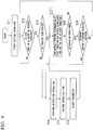
- FIG. 6 is a flowchart showing an example of the control method in an embodiment of the present invention.
- the operation executing unit 43 performs the defrosting operation of the DfR will be described as an example; however, the same control can also be applied to a case of performing the defrosting operation of the DfP.
- the control device 201 starts the heating operation (step S11). Specifically, the operation executing unit 43 controls the four way valve 7 such that refrigerant gas discharged from the compressor 2 circulates the heating path (the path connecting the first terminal 7A to the third terminal 7C, connecting the second terminal 7B to the fourth terminal 7D, and allowing the refrigerant gas to flow from the compressor 2 to the indoor heat exchanger 3), and closes the two way valve 6.
- the operation executing unit 43 determines whether the outside air temperature ThoA and the outdoor heat exchanger temperature ThoR satisfy the defrosting start condition M (for example, outside air temperature ThoA-outdoor heat exchanger temperature ThoR> ⁇ ) (step S12). In addition, at the start of the heating operation, the operation executing unit 43 may continue the heating operation without performing this determination during a predetermined prohibition period (for example, 35 minutes).
- step S12 When the temperature difference (ThoA-ThoR) does not exceed the predetermined constant ⁇ (step S12: No), the operation executing unit 43 continues the process of step S11 and continuously performs the heating operation.
- step S12 determines that the outdoor heat exchanger 5 is frosted.
- step S13 determines whether the present time is the prohibition period of the defrosting operation.
- step S14 the operation executing unit 43 performs the defrosting operation. Specifically, the operation executing unit 43 switches the four way valve 7 to the connection relation of the cooling path while keeping the two way valve 6 closed, and performs an operation. In this way, the discharged refrigerant gas is sent to the outdoor heat exchanger 5, so that defrosting is performed.
- the timer 46 measures an elapsed time after the start of the defrosting operation.
- the operation executing unit 43 records the start time of the defrosting operation in the storage unit 45 by using the timer 46.
- the operation executing unit 43 determines whether defrosting of the outdoor heat exchanger 5 has been achieved, and stops the defrosting operation when it is determined that the defrosting has been achieved. In relation to the determination regarding whether the defrosting has been achieved, for example, it may be determined that the defrosting has been achieved when the temperature difference (ThoA-ThoR) is within a predetermined threshold value. When a predetermined upper limit value has passed from the start of the defrosting operation, the operation executing unit 43 stops the defrosting operation.
- the operation executing unit 43 performs determination of time-up with the updated value.
- the operation executing unit 43 switches the four way valve 7 to the connection relation of the heating path and resumes the heating operation.
- the operation executing unit 43 records the end time of the defrosting operation in the storage unit 45 by using the timer 46.
- the timer 46 measures an elapsed time since entering the prohibition period.
- the operation executing unit 43 calculates the operation time of the defrosting operation by subtracting the start time of the defrosting operation from the end time of the defrosting operation, and records the calculated operation time in the storage unit 45 in correlation with the start time or the end time of a defrosting operation of this time (step S15).
- the parameter setting unit 44 adjusts the parameters related to the operational maintenance of the defrosting operation (step S16). For example, when the operation time of the defrosting operation recorded in the storage unit 45 has become short a predetermined number of consecutive times, the parameter setting unit 44 adds h3 (for example, 5 minutes) to a current prohibition period (for example, 35 minutes) and updates the prohibition period with the added value (for example, 40 minutes). Furthermore, when the operation time of the defrosting operation has become long a predetermined number of consecutive times, the parameter setting unit 44 subtracts h5 (for example, 5 minutes) from the current prohibition period (for example, 35 minutes) and updates the prohibition period with the subtracted value (for example, 30 minutes).
- h3 for example, 5 minutes
- a current prohibition period for example, 35 minutes
- the prohibition period with the added value for example, 40 minutes
- the parameter setting unit 44 subtracts h5 (for example, 5 minutes) from the current prohibition period (for example, 35 minutes) and updates the prohibition period with the subtracted value (for example, 30
- the parameter setting unit 44 adds h7 (for example, 5 minutes) to an upper limit value (for example, 15 minutes) of a current operation time and updates the upper limit value of the operation time with the added value (for example, 20 minutes).
- step S13 when the present time is the prohibition period of the defrosting operation (step S13: Yes) or when the defrosting operation ends and the prohibition period is reached, the operation executing unit 43 continuously performs the same determination as that of step S12. Then, when the start condition M is established, the operation executing unit 43 records the established time in the storage unit 45, and when the start condition M is not established, the operation executing unit 43 records the unestablished time in the storage unit 45 (step S17). Furthermore, the operation executing unit 43 determines whether the prohibition period has ended (step S18). For example, when the elapsed time from the start of the prohibition period measured by the timer 46 reaches a predetermined setting value (for example, 35 minutes), the operation executing unit 43 determines that the prohibition period has ended. When the length of the prohibition period has been updated in the process of step S16, the operation executing unit 43 performs determination with the updated value.
- a predetermined setting value for example, 35 minutes
- step S18 When the prohibition period has not ended (step S18; No), the operation executing unit 43 continuously performs the process of step S17.
- the operation executing unit 43 determines whether to perform the defrosting operation on the basis of the establishment state of the start condition M during the prohibition period (step S19). For example, on the basis of the established time and the unestablished time of the start condition M recorded in the storage unit 45, the operation executing unit 43 calculates the sum of the times during which the start condition M is established during the prohibition period. When the total time exceeds h1 (for example, 20 minutes), the operation executing unit 43 determines to perform the defrosting operation. Furthermore, when the start condition M has been established even once between the time before h2 after the end of the prohibition period and the end time, the operation executing unit 43 determines to perform the defrosting operation.
- step S19; Yes When it is determined to perform the defrosting operation (step S19; Yes), the operation executing unit 43 starts the defrosting operation immediately after the end of the prohibition period. That is, after the end of the prohibition period, the operation executing unit 43 performs the process of step S14 within a predetermined time (for example, within 30 seconds). When it is determined to perform no defrosting operation (step S19; No), the operation executing unit 43 continues the heating operation.
- the start condition M of the defrosting operation is established during the prohibition period of the defrosting operation, even when the start condition M is not established at the end of the prohibition period due to a subsequent sudden change in outside air temperature, it is possible to avoid non-execution of the defrosting operation, to perform the defrosting operation after the end of the prohibition period, and to perform defrosting. Furthermore, on the basis of the trend of the operation times of the past defrosting operations, when defrosting is not sufficient, it is possible to promote defrosting by shortening the prohibition period or extending the upper limit value of the defrosting operation time. When defrosting is performed more than necessary, it is possible to limit an opportunity of performing the defrosting operation by extending the prohibition period. By these functions, it is possible to realize the operational maintenance of the defrosting operation according to the design intention of the air conditioner 1.
- All functions or some functions of the control device 201 may be realized by hardware composed of a large scale integration (LSI), an application specific integrated circuit (ASIC), a programmable logic device (PLD), a field-programmable gate array (FPGA), an integrated circuit and the like.
- all functions or some functions of the control device 201 may be configured by a computer including a processor such as a CPU.
- the process of each processing in the control device 201 can be realized when the CPU and the like of the control device 201 execute a program.
- the program executed by the control device 201 may be recorded on a computer-readable recording medium, and the process of each processing may be realized when the program recorded on the recording medium is read and executed.
- control device 201 is assumed to include an OS and hardware such as a peripheral device.
- the computer-readable recording medium for example, is a portable medium such as a flexible disk, a magneto-optical disc, a ROM, and a CD-ROM, and a storage device such as a hard disk embedded in the control device 201.
- the computer-readable recording medium may also include a medium for dynamically holding a program for a short time period such as a communication line in the case where the program is transmitted via a network such as the Internet or a communication line such as a telephone line, and a medium for holding the program for a constant time period such as a volatile memory in a computer system serving as a server or a client in that case.
- the aforementioned program may also be a program for realizing some of the aforementioned functions, or a program capable of realizing the aforementioned functions in combination with a program in which the aforementioned functions have been previously recorded in the computer system.
Landscapes
- Engineering & Computer Science (AREA)
- Physics & Mathematics (AREA)
- Mechanical Engineering (AREA)
- Thermal Sciences (AREA)
- General Engineering & Computer Science (AREA)
- Air Conditioning Control Device (AREA)
Abstract
Description
- The present invention relates to a control device, an air conditioner, a control method, and a program.
- Priority is claimed on Japanese Patent Application No.
2018-61733, filed March 28, 2018 - When a heating operation of an air conditioner is performed in an environment in which outdoor air temperature is low, an outdoor unit may be frosted. In order to prevent the reduction of heating capacity due to frosting, a defrosting operation is performed to remove the frost of the outdoor unit. In general, conditions of an elapsed time from the end of a previous defrosting operation or outdoor air temperature and the temperature of an outdoor unit heat exchanger are set, and when the conditions are established, a defrosting operation is started in many cases.
- In contrast,
Patent Document 1 discloses a technology for deciding the start of a de-icing operation (a defrosting operation) with two conditional expressions including a linear equation employing the temperature of an outdoor unit heat exchanger and outdoor air temperature as variables. In the technology disclosed inPatent Document 1, values of parameters of the two conditional expressions are adjusted on the basis of an operation time of a previous de-icing operation. In this way, it is possible to start the de-icing operation at an appropriate timing according to a frosted state of the outdoor unit heat exchanger. - [Patent Document 1] Japanese Unexamined Patent Application, First Publication No.
2008-14593 - However, even though a start condition of the defrosting operation is established during a prohibition period of the defrosting operation, the start condition may not be established at the end of the prohibition period due to a sudden decrease and the like in the outdoor air temperature due to a change and the like in weather. In such a case, the defrosting operation may not be performed or the start of the defrosting operation may be delayed. Therefore, since the outdoor unit heat exchanger is frosted, there is a possibility that the performance of a heating operation is reduced or it is not possible to remove frost in a next defrosting operation.
- Therefore, an object of the present invention is to provide a control device, an air conditioner, a control method, and a program, by which it is possible to solve the above problems.
- According to an aspect of the present invention, the control device includes an operation executing unit that performs a defrosting operation after a prohibition period of the defrosting operation ends on the basis of an establishment state of a start condition of the defrosting operation during the prohibition period regardless of whether the start condition is established at an end time point of the prohibition period.
- According to an aspect of the present invention, when a total time, for which the start condition is established during the prohibition period, is equal to or more than a predetermined threshold value, the operation executing unit is configured to start the defrosting operation even though the start condition is not established at the end time point of the prohibition period.
- According to an aspect of the present invention, when the start condition is established with a predetermined time before the prohibition period ends, the operation executing unit is configured to start the defrosting operation even though the start condition is not established at the end time point of the prohibition period.
- According to an aspect of the present invention, the control device further includes a parameter setting unit that is configured to set a parameter related to an operational maintenance of the defrosting operation on the basis of a trend of operation times of defrosting operations performed in the past.
- According to an aspect of the present invention, when the operation times become shorter than an operation time of an immediately previous defrosting operation more than a predetermined number of consecutive times, the parameter setting unit is configured to increase the length of the prohibition period.
- According to an aspect of the present invention, when the operation times become longer than an operation time of an immediately previous defrosting operation more than a predetermined number of consecutive times, the parameter setting unit is configured to decrease the length of the prohibition period.
- According to an aspect of the present invention, when the operation times reach a predetermined upper limit value, which has been set for the defrosting operation, more than a predetermined number of consecutive times, the parameter setting unit is configured to increase the upper limit value.
- According to an aspect of the present invention, an air conditioner includes the control device according to any one of the above.
- According to an aspect of the present invention, a control method includes a step of calculating an establishment state of a start condition of a defrosting operation during a prohibition period of the defrosting operation, and a step of determining whether to perform the defrosting operation after the prohibition period ends on the basis of the establishment state regardless of whether the start condition is established at an end time point of the prohibition period.
- According to an aspect of the present invention, a program causes a computer to serve as a means that is configured to calculate an establishment state of a start condition of a defrosting operation during a prohibition period of the defrosting operation, and a means that is configured to determine whether to perform the defrosting operation after the prohibition period ends on the basis of the establishment state regardless of whether the start condition is established at an end time point of the prohibition period.
- According to the aforementioned control device, air conditioner, control method, and program, it is possible to prevent non-execution of a defrosting operation.
-
-
FIG. 1 is an overall view showing an example of an air conditioner in an embodiment of the present invention. -
FIG. 2 is a diagram showing a start condition of a defrosting operation in an embodiment of the present invention. -
FIG. 3 is a functional block diagram showing an example of a control device of an air conditioner in an embodiment of the present invention. -
FIG. 4 is a diagram showing a control method of a defrosting operation in an embodiment of the present invention. -
FIG. 5 is a diagram showing an adjustment method of parameters related to operational maintenance of a defrosting operation in an embodiment of the present invention. -
FIG. 6 is a flowchart showing an example of a control method in an embodiment of the present invention. - Hereinafter, defrost control in an air conditioner according to an embodiment of the present invention will be described with reference to
FIG. 1 to FIG. 6 . -
FIG. 1 is an overall view showing an example of an air conditioner in an embodiment of the present invention. - An
air conditioner 1 according to a first embodiment includes arefrigerant circuit 10. Therefrigerant circuit 10 includes acompressor 2, anindoor heat exchanger 3, anexpansion valve 4, an outdoor heat exchanger 5, a twoway valve 6, and a fourway valve 7. Thecompressor 2, theindoor heat exchanger 3, theexpansion valve 4, the outdoor heat exchanger 5, the twoway valve 6, and the fourway valve 7 are connected to arefrigerant pipe 20 capable of circulating a refrigerant. - The
refrigerant circuit 10 includes amain circuit 100 used in a heating operation, a positive cycle defrosting operation, and a reverse cycle defrosting operation, and abypass pipe 200 used only in the positive cycle defrosting operation. - The
main circuit 100 includes a heat exchanger-sidemain circuit 110 connected to afirst terminal 7A and asecond terminal 7B of terminals of the fourway valve 7, and a compressor-sidemain circuit 120 connected to athird terminal 7C and afourth terminal 7D of the terminals of the fourway valve 7 when starting from the fourway valve 7. In other words, the heat exchanger-sidemain circuit 110 and the compressor-sidemain circuit 120 are connected to each other via the fourway valve 7. - The heat exchanger-side
main circuit 110 is provided with theindoor heat exchanger 3, theexpansion valve 4, the outdoor heat exchanger 5. The compressor-sidemain circuit 120 is provided with thecompressor 2. - In the four
way valve 7, four pipelines connected to the terminals can be connected by two pairs or these pairs can be switched. Specifically, the fourway valve 7 can connect a pair of thefirst terminal 7A and thefourth terminal 7D and a pair of thesecond terminal 7B and thethird terminal 7C. Furthermore, the fourway valve 7 can connect a pair of thefirst terminal 7A and thethird terminal 7C and a pair of thesecond terminal 7B and thefourth terminal 7D. - In this way, it is possible to switch a connection relation between the heat exchanger-side
main circuit 110 and the compressor-sidemain circuit 120. When thesecond terminal 7B and thethird terminal 7C of the fourway valve 7 are connected to each other, a high temperature and high pressure refrigerant discharged from thecompressor 2 flows through a path (a cooling path) from thesecond terminal 7B to the outdoor heat exchanger 5. When thefirst terminal 7A and thethird terminal 7C of the fourway valve 7 are connected to each other, the high temperature and high pressure refrigerant discharged from thecompressor 2 flows through a path (a heating path) from thefirst terminal 7A to theindoor heat exchanger 3. - The
refrigerant circuit 10 of theair conditioner 1 is provided with thebypass pipe 200 as described above. Thebypass pipe 200 is a refrigerant pipe that connects between thecompressor 2 and the four way valve 7 (between abypass start point 20A and abypass end point 20B provided between theexpansion valve 4 and the outdoor heat exchanger 5 of the heat exchanger-side main circuit 110) at a discharge side of thecompressor 2 of the compressor-sidemain circuit 120. Thebypass pipe 200 is provided with the twoway valve 6, so that it is possible to open and close thebypass pipe 200. In the normal heating operation, the cooling operation, and the reverse cycle defrosting operation, the twoway valve 6 is closed. - Circulation of a refrigerant in a heating operation will be described. In the heating operation, the four
way valve 7 is in the connection relation of the heating path. The refrigerant is compressed by thecompressor 2 to reach high temperature and high pressure, enters thethird terminal 7C of the fourway valve 7, and then flows from thefirst terminal 7A to theindoor heat exchanger 3. In theindoor heat exchanger 3, the refrigerant is cooled and condensed by heat exchange, and instead, heat is given to indoor air outside theindoor heat exchanger 3. The indoor air is blown by an indoor-side blower 13. The condensed refrigerant flows into theexpansion valve 4 and reaches low temperature and low pressure. The refrigerant exiting theexpansion valve 4 flows into the outdoor heat exchanger 5, is heated by outdoor air, and is evaporated and vaporized in the outdoor heat exchanger 5. The vaporized refrigerant returns to thecompressor 2 through thesecond terminal 7B and thefourth terminal 7D of the fourway valve 7. By continuously repeating the above cycle, theair conditioner 1 performs the heating operation. - During the heating operation, since the temperature of the air outside the outdoor heat exchanger 5 is deprived of heat by the refrigerant and becomes lower as described above, the temperature of the surface of the outdoor heat exchanger 5 is lowered to a subzero temperature range, and therefore frost may occur and may form layers. Therefore, heat conduction of the heat exchanger may be disturbed and thus heat exchange efficiency may be reduced.
- In order to remove the frost, two types of defrosting operations are known. That is, there are a positive cycle defrosting operation (a bypass cycle defrosting operation, hereinafter, referred to as DfP) and a reverse cycle defrosting operation (hereinafter, referred to as DfR).
- The DfP indicates a defrosting operation for defrosting the outdoor heat exchanger 5 by circulating the refrigerant via the
bypass pipe 200 that sends some of refrigerant gas discharged from thecompressor 2 to the outdoor heat exchanger 5 during the heating operation. By opening the twoway valve 6, the DfP is performed. - The circulation of the refrigerant during the DfP will be described. During the DfP, the connection relation of the heating path is maintained in the four
way valve 7, so that the refrigerant circulation during the aforementioned heating operation is maintained. In addition, the twoway valve 6 is opened and the refrigerant also flows through thebypass pipe 200, so that some of the high temperature and high pressure refrigerant discharged from thecompressor 2 is sent to the outdoor heat exchanger 5 without passing through theindoor heat exchanger 3. In this way, heat is applied to the outdoor heat exchanger 5 to perform defrosting. - In addition, in the DfP, since some of the high temperature and high pressure refrigerant to be originally sent to the
indoor heat exchanger 3 is sent to the outdoor heat exchanger 5, it is possible to continue the heating operation while performing the defrosting, but the heating capability is reduced to about 1/3 as compared with the normal heating operation. Furthermore, since the amount of the refrigerant sent to the outdoor heat exchanger 5 is a part of the total refrigerant, the defrosting capability becomes lower as compared with the DfR to be described later. - On the other hand, the DfR indicates a defrosting operation in which defrosting is performed by circulating the refrigerant in the heat exchanger-side
main circuit 1 10 in a direction opposite to that of the heating operation. The refrigerant is circulated in the direction opposite to that of the heating operation, so that all of the refrigerant gas discharged from thecompressor 2 is sent to the outdoor heat exchanger 5. In this way, in the DfR, it is possible to strongly melt frost as compared with the DfP. However, since the DfR is performed by switching the fourway valve 7 to the connection relation of the cooling path, substantially the same refrigerant circulation as that in the cooling operation is performed except that air is not blown to theindoor heat exchanger 3. Therefore, during the DfR, since the heating operation is stopped and indoor heat deprived, the room temperature drops. - The circulation of the refrigerant during the DfR will be described. The refrigerant is compressed by the
compressor 2 to reach high temperature and high pressure, enters thethird terminal 7C of the fourway valve 7, and then flows from thesecond terminal 7B to the outdoor heat exchanger 5. In the outdoor heat exchanger 5, the refrigerant is cooled and condensed by heat exchange, and instead, heat is given to outdoor air outside the outdoor heat exchanger 5. Therefore, the condensed refrigerant flows into theexpansion valve 4 and reaches low temperature and low pressure. The refrigerant exiting theexpansion valve 4 flows into theindoor heat exchanger 3, is heated by indoor air, and is evaporated and vaporized in theindoor heat exchanger 3. At this time, heat is taken away from indoor air outside theindoor heat exchanger 3. In the cooling operation, the indoor air that has reached low temperature is blown by the indoor-side blower 13 and is used for indoor cooling, but in the DfR, no air is blown. The vaporized refrigerant enters thefirst terminal 7A of the fourway valve 7, and returns to thecompressor 2 through the fourth terminal 7D. - The aforementioned cycle is continuously repeated.
- In the present embodiment, the
air conditioner 1 is further provided with an outsideair temperature sensor 25 and a heatexchanger temperature sensor 35, and further includes acontrol device 201 for switching the three operation modes of the aforementioned heating operation, DfP and DfR. A start condition M of the defrosting operation (DfP or DfR) will be described usingFIG. 2 . -
FIG. 2 is a diagram showing the start condition of the defrosting operation in an embodiment of the present invention. A line L1 shown inFIG. 2 denotes the start condition M of the defrosting operation when an outdoor heat exchanger temperature ThoR is set as a vertical axis and an outside air temperature ThoA is set as a horizontal axis. This relation, for example, can be expressed by α (=outside air temperature ThoA-outdoor heat exchanger temperature ThoR) (α is a predetermined constant). The outdoor heat exchanger temperature ThoR is a temperature measured by the heatexchanger temperature sensor 35. The outside air temperature ThoA is a temperature measured by the outsideair temperature sensor 25. - When the relation between the outdoor heat exchanger temperature ThoR and the outside air temperature ThoA is in a region below the line L1 (outside air temperature ThoA-outdoor heat exchanger temperature ThoR≥α), for example, when the outside air temperature ThoA and the outdoor heat exchanger temperature ThoR are in a relation indicated by a point P1, the start condition M of the defrosting operation is established.
- When the relation between the outdoor heat exchanger temperature ThoR and the outside air temperature ThoA is in a region above the line L1 (outside air temperature ThoA-outdoor heat exchanger temperature ThoR<α), for example, when they are in a relation indicated by a point P2, the start condition M of the defrosting operation is not established.
- During the heating operation, when the relation between the outdoor heat exchanger temperature ThoR and the outside air temperature ThoA satisfies the start condition M of the defrosting operation, the
control device 201 stops the heating operation and starts the defrosting operation of the DfP or the DfR. When the defrosting operation is started and a predetermined stop condition of the defrosting operation is established, thecontrol device 201 stops the defrosting operation and resumes the heating operation. The stop condition of the defrosting operation, for example, is that the temperature difference (ThoA-ThoR) is within a predetermined threshold value. Furthermore, an upper limit value is set for the operation time of the defrosting operation. When the upper limit value passes from the start of the defrosting operation, thecontrol device 201 ends the defrosting operation. Furthermore, as described above, since the defrosting operation reduces the capability of the original heating operation, when the defrosting operation is performed once, execution is prohibited for a while (a predetermined prohibition period). That is, even though the start condition M of the defrosting operation is established during this prohibition period, thecontrol device 201 performs no defrosting operation during the prohibition period. - For example, it is assumed that the relation between the outdoor heat exchanger temperature ThoR and the outside air temperature ThoA is the relation indicated by the point P1 during the prohibition period of the defrosting operation. When the same relation is maintained after the prohibition period passes, the
control device 201 starts the defrosting operation after the end of the prohibition period. However, it is assumed that when the outside air temperature suddenly decreases before the end of the prohibition period, the relation between the outdoor heat exchanger temperature ThoR and the outside air temperature ThoA is changed to a relation indicated by a point P3 and is maintained. Then, even though the prohibition period passes, since the start condition M of the defrosting operation is not established, thecontrol device 201 performs no defrosting operation. In such a case, while the start condition M of the defrosting operation is established during the prohibition period, there is a possibility that the outdoor heat exchanger 5 is frosted. However, in the related control, until the outdoor heat exchanger temperature ThoR decreases due to the outside air temperature ThoA, for example, they are in a relation as indicated by a point P4, since thecontrol device 201 performs no defrosting operation, the heating operation is in an operation state with low efficiency during that time period. In contrast, thecontrol device 201 of the present embodiment has a function of starting the defrosting operation according to the establishment state of a frost formation condition during the prohibition period after the end of the prohibition period of the defrosting operation. - Next, the function of the
control device 201 will be described usingFIG. 3 . -
FIG. 3 is a functional block diagram showing an example of the control device of the air conditioner in an embodiment of the present invention. - As shown in
FIG. 3 , an outdoor unit 1A includes thecontrol device 201. Thecontrol device 201, for example, is a computer including a central processing unit (CPU) and the like. Thecontrol device 201 includes an outside airtemperature acquiring unit 41, an outdoor heat exchangertemperature acquiring unit 42, anoperation executing unit 43, aparameter setting unit 44, astorage unit 45, and atimer 46. - The outside air
temperature acquiring unit 41 acquires the outside air temperature (outside air temperature ThoA) of the outdoor unit 1A through the outsideair temperature sensor 25. - The outdoor heat exchanger
temperature acquiring unit 42 acquires the temperature (outdoor heat exchanger temperature ThoR) of the outdoor heat exchanger 5 of the outdoor unit 1A through the heatexchanger temperature sensor 35. - The
operation executing unit 43 performs the heating operation and the defrosting operation. Theoperation executing unit 43 switches the heating operation and the defrosting operation by mainly controlling the twoway valve 6 and the fourway valve 7. For example, when the start condition M of the defrosting operation is established, theoperation executing unit 43 switches the heating operation to the defrosting operation. Furthermore, for example, when the end condition of the defrosting operation is established, theoperation executing unit 43 switches the defrosting operation to the heating operation. As described above, theoperation executing unit 43 can perform the defrosting operation of the DfP or the DfR. Theoperation executing unit 43, for example, may select the DfP or the DfR in accordance with the temperature difference between the outdoor heat exchanger temperature ThoR and the outside air temperature ThoA, and perform the selected type of defrosting operation. In addition, since a control method for preventing the non-execution of the defrosting operation according to the present embodiment can be applied without distinction between the DfP and the DfR, the defrosting operation will be described without particular distinction in the following description. On the basis of the establishment state of the start condition M of the defrosting operation during the prohibition period of the defrosting operation, theoperation executing unit 43 performs the defrosting operation regardless of whether the start condition M is established at the end time point of the prohibition period. - The
parameter setting unit 44 sets parameters related to the operational maintenance of the defrosting operation. The parameters related to the operational maintenance, for example, include a length of the prohibition period, the upper limit value of the operation time of the defrosting operation, and the like. On the basis of the trend of operation times of defrosting operations performed in the past, theparameter setting unit 44 appropriately adjusts the parameters related to the operational maintenance of the defrosting operation. - The
storage unit 45 stores various types of information of the outside air temperature ThoA, the outdoor heat exchanger temperature ThoR, the parameters such as the length of the prohibition period and the upper limit value of the operation time of the defrosting operation, and the like. - The
timer 46 measures time. - Next, start control of the defrosting operation based on the establishment state of the defrosting operation start condition during the prohibition period according to the present embodiment will be described.
-
FIG. 4 is a diagram showing the control method of the defrosting operation in an embodiment of the present invention.FIG. 4 (a) shows related defrost control. The time T1 to the time T2 is the prohibition period of the defrosting operation. It is assumed that at the time T4 to the time T4' of the prohibition period, the start condition M is established and then the prohibition period ends due to the non-establishment of the start condition M. At the end of the prohibition period, the start condition M is not established. In such a case, in the related control, the defrosting operation is not performed immediately after the end of the prohibition period. Thereafter, when the start condition M is established at the time T3, the defrosting operation is started. In the case of such control, frost formation may occur from the time T1 to the time T2, and in the heating operation from the time T2 to the time T3, heating capacity may be reduced. -
FIG. 4 (b) to FIG. 4 (d) show the defrost control of the present embodiment.FIG. 4 (b) shows a control method of the defrosting operation when thecontrol device 201 of the present embodiment has operated theair conditioner 1 in the same operation state as that ofFIG. 4 (a) . That is, at the time T4 to the time T4' of the prohibition period, the start condition M of the defrosting operation is established, and then the prohibition period ends due to the non-establishment of the start condition M. Theoperation executing unit 43 calculates the period of time between the time T4 and the time T4', in which the start condition M of the defrosting operation is established, by using thetimer 46. When the calculated period of time is equal to or more than a predetermined period of time "h1", theoperation executing unit 43 starts the defrosting operation after the end of the prohibition period of the defrosting operation (the time T2). In such a case, it is irrelevant whether the start condition M is established at the time T2. -
FIG. 4 (c) shows a case where the start condition M of the defrosting operation has been established at each of the times T5 to T5', the times T6 to T6', and the times T7 to T7' of the prohibition period and the prohibition period has ended with the start condition M not being established. In such a case, theoperation executing unit 43 calculates each period of time between the times T5 to T5', the times T6 to T6', and the times T7 to T7', in which the start condition M of the defrosting operation has been established, by using thetimer 46, and calculates the sum of the three time zones in which the start condition M has been established. When the calculated total time is equal to or more than the predetermined period of time "h1", theoperation executing unit 43 starts the defrosting operation at the time T2 even though the start condition M has not been established at the time T2 at which the prohibition period ends. -
FIG. 4 (d) shows a case where the start condition M of the defrosting operation has been established once within a predetermined period of time "h2" immediately before the prohibition period ends and the prohibition period has ended with the start condition M not being established. In such a case, by using thetimer 46, theoperation executing unit 43 confirms whether the start condition M has been established after the time T8 before "h2" with reference to the time T2 at which the prohibition period ends. When the start condition M has been established even once in this time zone, theoperation executing unit 43 starts the defrosting operation even though the start condition M is not established at the time T2. - According to the control method of the defrosting operation shown in
FIG. 4 (b) to FIG. 4 (d) , (A) when the total time in which the start condition M is established during the prohibition period is equal to or more than the predetermined period of time "h1" or (B) when the start condition M is established even once within the predetermined period of time "h2" before the end of the prohibition, the defrosting operation is started immediately after the prohibition period ends regardless of whether the start condition M is established at the end time point of the prohibition period. In this way, even in a state in which frost formation is proceeding during the prohibition period, it is possible to quickly perform defrosting after the end of the prohibition period and to prevent the reduction of heating capability. In addition, the length of the prohibition period, for example, is 35 minutes, the predetermined period of time "h1", for example, is 20 minutes, and the predetermined period of time "h2", for example, is 3 minutes. - Next, a method for adjusting the parameters related to the operational maintenance of the defrosting operation according to the present embodiment will be described.
-
FIG. 5 is a diagram showing an adjustment method of the parameters related to the operational maintenance of the defrosting operation in an embodiment of the present invention. -
FIG. 5 (a) shows a case where an execution time Dx (x: 1 to n) of the defrosting operation has been continuously shortened n times. That is, D1>D2>···>Dn. Such a case is considered to be an operational environment (the outside air temperature ThoA, the outdoor heat exchanger temperature ThoR and the like) in which frost hardly occurs. Accordingly, since the necessity to perform the defrosting operation is relatively low, it is preferable that a long time is allocated to the heating operation as much as possible. Accordingly, theparameter setting unit 44 sets the length of the prohibition period longer by a predetermined period of time "h3". In this way, it is possible to decrease the number of opportunities of performing the defrosting operation and to prevent the heating operation from being disturbed more than necessary. In addition, after the prohibition period is adjusted, when the execution time of the defrosting operation is continuously shortened n times, the predetermined period of time "h3" may be further added with a predetermined period of time "h4" for an initial value (for example, 35 minutes) of the prohibition period as an upper limit value of an increment. In addition, the value "h3" to be added at a time, for example, is 5 minutes and the upper limit value "h4", for example, is 10 minutes. -
FIG. 5 (b) shows a case where the execution time Dx (x: 1 to n) of the defrosting operation has been continuously increased n times. That is, D1<D2<···<Dn. Such a case is considered to be an operational environment in which frost easily occurs or a state in which defrosting is not possible in a one-time defrosting operation and unmelted frost easily occurs. Accordingly, it is preferable to increase the number of executions of the defrosting operation and to operate the defrosting operation such that defrosting can be reliably performed. Accordingly, theparameter setting unit 44 sets the length of the prohibition period shorter by a predetermined period of time "h5". In this way, it is possible to increase the number of opportunities of performing the defrosting operation and to prevent frost formation and unmelted frost. In addition, after the prohibition period is adjusted, when the execution time of the defrosting operation is continuously increased n times, the predetermined period of time "h5" may be further subtracted with a predetermined period of time "h6" for the initial value (for example, 35 minutes) of the prohibition period as an upper limit value of a decrement. In addition, the value "h5" to be subtracted at a time, for example, is 5 minutes, and the upper limit value "h6", for example, is 10 minutes. -
FIG. 5 (c) shows a case where the execution time Dx (x: 1 to n) of the defrosting operation has continuously expired n times. That is, D1=D2=···=Dn=upper limit value (for example, is 15 minutes) of the execution time of the defrosting operation. Such a case is considered to be an operational environment in which frost easily occurs or a state in which defrosting is not possible in a one-time defrosting operation and unmelted frost easily occurs. Accordingly, it is preferable to increase the execution time of the defrosting operation and to operate the defrosting operation such that defrosting can be performed without unmelted frost. Accordingly, theparameter setting unit 44 sets the upper limit value of the operation time longer by a predetermined period of time "h7". In this way, it is possible to increase the execution time of the defrosting operation and to prevent frost formation and unmelted frost. In addition, after the operation time is adjusted, when the defrosting operation has continuously expired n times, the predetermined period of time "h7" may be further added with a predetermined period of time "h8" for the initial value (for example, 15 minutes) of the operation time as an upper limit value. In addition, the value "h7" to be added at a time, for example, is 5 minutes and the upper limit value "h8", for example, is 10 minutes. - In addition, even though the execution time of the defrosting operation has continuously expired n times, the length of the prohibition period may be set shorter by "h5" in the same manner as the adjustment described in
FIG. 5 (b) . - According to the adjustment method of the operational parameters shown in
FIG. 5 (a) to FIG. 5 (c) , on the basis of the trend of the operation times of the defrosting operation, (a) when the operation time of the defrosting operation of each time has been shorter than an operation time at the time of immediately previous execution more than a predetermined number of consecutive times up to a defrosting operation performed previous time, the length of the prohibition period is increased. Furthermore, (b) when the operation time of the defrosting operation of each time has been longer than an operation time at the time of immediately previous execution more than a predetermined number of consecutive times up to a defrosting operation performed previous time, the length of the prohibition period is decreased. Furthermore, (c) when the operation time of each time has reached an upper limit value of the operation time more than a predetermined number of consecutive times up to a defrosting operation performed previous time, the upper limit value of the operation time is increased. In this way, it is possible to appropriately adjust the operational maintenance of the defrosting operation in accordance with a frosting state, and it is possible to prevent the reduction of heating capacity by preventing the progression of frost formation and unmelted frost. - Next, the process flow of the execution control of the defrosting operation will be described using
FIG. 6 . -
FIG. 6 is a flowchart showing an example of the control method in an embodiment of the present invention. In addition, in the following description, a case where theoperation executing unit 43 performs the defrosting operation of the DfR will be described as an example; however, the same control can also be applied to a case of performing the defrosting operation of the DfP. - Firstly, when a user starts to use heating. Then, the
control device 201 starts the heating operation (step S11). Specifically, theoperation executing unit 43 controls the fourway valve 7 such that refrigerant gas discharged from thecompressor 2 circulates the heating path (the path connecting thefirst terminal 7A to thethird terminal 7C, connecting thesecond terminal 7B to the fourth terminal 7D, and allowing the refrigerant gas to flow from thecompressor 2 to the indoor heat exchanger 3), and closes the twoway valve 6. Next, theoperation executing unit 43 determines whether the outside air temperature ThoA and the outdoor heat exchanger temperature ThoR satisfy the defrosting start condition M (for example, outside air temperature ThoA-outdoor heat exchanger temperature ThoR>α) (step S12). In addition, at the start of the heating operation, theoperation executing unit 43 may continue the heating operation without performing this determination during a predetermined prohibition period (for example, 35 minutes). - When the temperature difference (ThoA-ThoR) does not exceed the predetermined constant α (step S12: No), the
operation executing unit 43 continues the process of step S11 and continuously performs the heating operation. - When the temperature difference (ThoA-ThoR) exceeds α (step S12: Yes), the
operation executing unit 43 determines that the outdoor heat exchanger 5 is frosted. Next, theoperation executing unit 43 determines whether the present time is the prohibition period of the defrosting operation (step S13). When the present time is not the prohibition period of the defrosting operation (step S13: No), theoperation executing unit 43 performs the defrosting operation (step S14). Specifically, theoperation executing unit 43 switches the fourway valve 7 to the connection relation of the cooling path while keeping the twoway valve 6 closed, and performs an operation. In this way, the discharged refrigerant gas is sent to the outdoor heat exchanger 5, so that defrosting is performed. Thetimer 46 measures an elapsed time after the start of the defrosting operation. Theoperation executing unit 43 records the start time of the defrosting operation in thestorage unit 45 by using thetimer 46. Next, theoperation executing unit 43 determines whether defrosting of the outdoor heat exchanger 5 has been achieved, and stops the defrosting operation when it is determined that the defrosting has been achieved. In relation to the determination regarding whether the defrosting has been achieved, for example, it may be determined that the defrosting has been achieved when the temperature difference (ThoA-ThoR) is within a predetermined threshold value. When a predetermined upper limit value has passed from the start of the defrosting operation, theoperation executing unit 43 stops the defrosting operation. In addition, when the upper limit value of the operation time of the defrosting operation is updated in step S16 to be described later, theoperation executing unit 43 performs determination of time-up with the updated value. When the defrosting operation ends, theoperation executing unit 43 switches the fourway valve 7 to the connection relation of the heating path and resumes the heating operation. Furthermore, theoperation executing unit 43 records the end time of the defrosting operation in thestorage unit 45 by using thetimer 46. When the defrosting operation ends, the prohibition period of the defrosting operation is reached. Thetimer 46 measures an elapsed time since entering the prohibition period. - Next, the
operation executing unit 43 calculates the operation time of the defrosting operation by subtracting the start time of the defrosting operation from the end time of the defrosting operation, and records the calculated operation time in thestorage unit 45 in correlation with the start time or the end time of a defrosting operation of this time (step S15). - Next, the
parameter setting unit 44 adjusts the parameters related to the operational maintenance of the defrosting operation (step S16). For example, when the operation time of the defrosting operation recorded in thestorage unit 45 has become short a predetermined number of consecutive times, theparameter setting unit 44 adds h3 (for example, 5 minutes) to a current prohibition period (for example, 35 minutes) and updates the prohibition period with the added value (for example, 40 minutes). Furthermore, when the operation time of the defrosting operation has become long a predetermined number of consecutive times, theparameter setting unit 44 subtracts h5 (for example, 5 minutes) from the current prohibition period (for example, 35 minutes) and updates the prohibition period with the subtracted value (for example, 30 minutes). Furthermore, when the operation time of the defrosting operation has expired a predetermined number of consecutive times, theparameter setting unit 44 adds h7 (for example, 5 minutes) to an upper limit value (for example, 15 minutes) of a current operation time and updates the upper limit value of the operation time with the added value (for example, 20 minutes). - On the other hand, when the present time is the prohibition period of the defrosting operation (step S13: Yes) or when the defrosting operation ends and the prohibition period is reached, the
operation executing unit 43 continuously performs the same determination as that of step S12. Then, when the start condition M is established, theoperation executing unit 43 records the established time in thestorage unit 45, and when the start condition M is not established, theoperation executing unit 43 records the unestablished time in the storage unit 45 (step S17). Furthermore, theoperation executing unit 43 determines whether the prohibition period has ended (step S18). For example, when the elapsed time from the start of the prohibition period measured by thetimer 46 reaches a predetermined setting value (for example, 35 minutes), theoperation executing unit 43 determines that the prohibition period has ended. When the length of the prohibition period has been updated in the process of step S16, theoperation executing unit 43 performs determination with the updated value. - When the prohibition period has not ended (step S18; No), the
operation executing unit 43 continuously performs the process of step S17. - When the prohibition period has ended (step S18; Yes), the
operation executing unit 43 determines whether to perform the defrosting operation on the basis of the establishment state of the start condition M during the prohibition period (step S19). For example, on the basis of the established time and the unestablished time of the start condition M recorded in thestorage unit 45, theoperation executing unit 43 calculates the sum of the times during which the start condition M is established during the prohibition period. When the total time exceeds h1 (for example, 20 minutes), theoperation executing unit 43 determines to perform the defrosting operation. Furthermore, when the start condition M has been established even once between the time before h2 after the end of the prohibition period and the end time, theoperation executing unit 43 determines to perform the defrosting operation. When it is determined to perform the defrosting operation (step S19; Yes), theoperation executing unit 43 starts the defrosting operation immediately after the end of the prohibition period. That is, after the end of the prohibition period, theoperation executing unit 43 performs the process of step S14 within a predetermined time (for example, within 30 seconds). When it is determined to perform no defrosting operation (step S19; No), theoperation executing unit 43 continues the heating operation. - According to the present embodiment, even though the start condition M of the defrosting operation is established during the prohibition period of the defrosting operation, even when the start condition M is not established at the end of the prohibition period due to a subsequent sudden change in outside air temperature, it is possible to avoid non-execution of the defrosting operation, to perform the defrosting operation after the end of the prohibition period, and to perform defrosting. Furthermore, on the basis of the trend of the operation times of the past defrosting operations, when defrosting is not sufficient, it is possible to promote defrosting by shortening the prohibition period or extending the upper limit value of the defrosting operation time. When defrosting is performed more than necessary, it is possible to limit an opportunity of performing the defrosting operation by extending the prohibition period. By these functions, it is possible to realize the operational maintenance of the defrosting operation according to the design intention of the
air conditioner 1. - All functions or some functions of the
control device 201, for example, may be realized by hardware composed of a large scale integration (LSI), an application specific integrated circuit (ASIC), a programmable logic device (PLD), a field-programmable gate array (FPGA), an integrated circuit and the like. Furthermore, all functions or some functions of thecontrol device 201, for example, may be configured by a computer including a processor such as a CPU. In such a case, the process of each processing in thecontrol device 201, for example, can be realized when the CPU and the like of thecontrol device 201 execute a program. The program executed by thecontrol device 201 may be recorded on a computer-readable recording medium, and the process of each processing may be realized when the program recorded on the recording medium is read and executed. In addition, thecontrol device 201 is assumed to include an OS and hardware such as a peripheral device. Furthermore, the computer-readable recording medium, for example, is a portable medium such as a flexible disk, a magneto-optical disc, a ROM, and a CD-ROM, and a storage device such as a hard disk embedded in thecontrol device 201. Furthermore, the computer-readable recording medium may also include a medium for dynamically holding a program for a short time period such as a communication line in the case where the program is transmitted via a network such as the Internet or a communication line such as a telephone line, and a medium for holding the program for a constant time period such as a volatile memory in a computer system serving as a server or a client in that case. Furthermore, the aforementioned program may also be a program for realizing some of the aforementioned functions, or a program capable of realizing the aforementioned functions in combination with a program in which the aforementioned functions have been previously recorded in the computer system. - Besides, the elements in the aforementioned embodiment can be appropriately replaced with well-known elements without departing from the scope of the present invention. Furthermore, the technical range of the present invention is not limited to the aforementioned embodiment and various modifications can be made within the scope of the present invention.
-
- 1 Air conditioner
- 1A Outdoor unit
- 201 Control device
- 2 Compressor
- 3 Indoor heat exchanger
- 4 Expansion valve
- 5 Outdoor heat exchanger
- 6 Two way valve
- 7 Four way valve
- 7A First terminal
- 7B Second terminal
- 7C Third terminal
- 7D Fourth terminal
- 10 Refrigerant circuit
- 20 Refrigerant pipe
- 20A Bypass start point
- 20B Bypass end point
- 200 Bypass pipe
- 100 Main circuit
- 110 Heat exchanger-side main circuit
- 120 Compressor-side main circuit
- 201 Control device
- 41 Outside air temperature acquiring unit
- 42 Outdoor heat exchanger temperature acquiring unit
- 43 Operation executing unit
- 44 Parameter setting unit
- 45 Storage unit
- 46 Timer
Claims (10)
- A control device comprising:
an operation executing unit configured to perform a defrosting operation after a prohibition period of the defrosting operation ends on the basis of an establishment state of a start condition of the defrosting operation during the prohibition period regardless of whether the start condition is established at an end time point of the prohibition period. - The control device according to claim 1, wherein, when a total time, for which the start condition is established during the prohibition period, is equal to or more than a predetermined threshold value, the operation executing unit is configured to start the defrosting operation even though the start condition is not established at the end time point of the prohibition period.
- The control device according to claim 1 or 2, wherein, when the start condition is established with a predetermined time before the prohibition period ends, the operation executing unit is configured to start the defrosting operation even though the start condition is not established at the end time point of the prohibition period.
- The control device according to any one of claims 1 to 3, further comprising:
a parameter setting unit configured to set a parameter related to an operational maintenance of the defrosting operation on the basis of a trend of operation times of defrosting operations performed in the past. - The control device according to claim 4, wherein, when the operation times become shorter than an operation time of an immediately previous defrosting operation more than a predetermined number of consecutive times, the parameter setting unit is configured to increase a length of the prohibition period.
- The control device according to claim 4 or 5, wherein, when the operation times become longer than an operation time of an immediately previous defrosting operation more than a predetermined number of consecutive times, the parameter setting unit is configured to decrease the length of the prohibition period.
- The control device according to any one of claims 4 to 6, wherein, when the operation times reach a predetermined upper limit value, which has been set for the defrosting operation, more than a predetermined number of consecutive times, the parameter setting unit is configured to increase the upper limit value.
- An air conditioner comprising the control device according to any one of claims 1 to 7.
- A control method comprising:a step of calculating an establishment state of a start condition of a defrosting operation during a prohibition period of the defrosting operation; anda step of determining whether to perform the defrosting operation after the prohibition period ends on the basis of the establishment state regardless of whether the start condition is established at an end time point of the prohibition period.
- A program causing a computer to serve as:a means that is configured to calculate an establishment state of a start condition of a defrosting operation during a prohibition period of the defrosting operation; anda means that is configured to determine whether to perform the defrosting operation after the prohibition period ends on the basis of the establishment state regardless of whether the start condition is established at an end time point of the prohibition period.
Applications Claiming Priority (1)
| Application Number | Priority Date | Filing Date | Title |
|---|---|---|---|
| JP2018061733A JP7049148B2 (en) | 2018-03-28 | 2018-03-28 | Controls, air conditioners, control methods and programs |
Publications (1)
| Publication Number | Publication Date |
|---|---|
| EP3546853A1 true EP3546853A1 (en) | 2019-10-02 |
Family
ID=65904295
Family Applications (1)
| Application Number | Title | Priority Date | Filing Date |
|---|---|---|---|
| EP19164543.1A Withdrawn EP3546853A1 (en) | 2018-03-28 | 2019-03-22 | Control device, air conditioner, control method, and program |
Country Status (3)
| Country | Link |
|---|---|
| EP (1) | EP3546853A1 (en) |
| JP (1) | JP7049148B2 (en) |
| AU (1) | AU2019201790B2 (en) |
Cited By (1)
| Publication number | Priority date | Publication date | Assignee | Title |
|---|---|---|---|---|
| CN116465064A (en) * | 2023-03-14 | 2023-07-21 | 宁波奥克斯电气股份有限公司 | Air conditioner control method and air conditioner |
Citations (5)
| Publication number | Priority date | Publication date | Assignee | Title |
|---|---|---|---|---|
| JP2008014593A (en) | 2006-07-07 | 2008-01-24 | Matsushita Electric Ind Co Ltd | Air conditioner |
| US20090266093A1 (en) * | 2005-07-26 | 2009-10-29 | Mitsubishi Electric Corporation | Refrigerating air conditioning system |
| DE112013002239T5 (en) * | 2012-04-27 | 2015-01-15 | Denso Corporation | heat pump device |
| US9897349B2 (en) * | 2013-05-24 | 2018-02-20 | Mitsubishi Electric Corporation | Refrigeration cycle device |
| JP2018061733A (en) | 2016-10-14 | 2018-04-19 | 株式会社平和 | Game machine |
Family Cites Families (3)
| Publication number | Priority date | Publication date | Assignee | Title |
|---|---|---|---|---|
| JP2002130876A (en) | 2000-10-18 | 2002-05-09 | Saginomiya Seisakusho Inc | Control device for air conditioner |
| JP4920316B2 (en) | 2006-06-16 | 2012-04-18 | 株式会社コロナ | Heat pump water heater |
| JP5939764B2 (en) | 2011-11-02 | 2016-06-22 | 三菱電機株式会社 | Heat pump device and heat pump water heater |
-
2018
- 2018-03-28 JP JP2018061733A patent/JP7049148B2/en active Active
-
2019
- 2019-03-15 AU AU2019201790A patent/AU2019201790B2/en active Active
- 2019-03-22 EP EP19164543.1A patent/EP3546853A1/en not_active Withdrawn
Patent Citations (5)
| Publication number | Priority date | Publication date | Assignee | Title |
|---|---|---|---|---|
| US20090266093A1 (en) * | 2005-07-26 | 2009-10-29 | Mitsubishi Electric Corporation | Refrigerating air conditioning system |
| JP2008014593A (en) | 2006-07-07 | 2008-01-24 | Matsushita Electric Ind Co Ltd | Air conditioner |
| DE112013002239T5 (en) * | 2012-04-27 | 2015-01-15 | Denso Corporation | heat pump device |
| US9897349B2 (en) * | 2013-05-24 | 2018-02-20 | Mitsubishi Electric Corporation | Refrigeration cycle device |
| JP2018061733A (en) | 2016-10-14 | 2018-04-19 | 株式会社平和 | Game machine |
Cited By (2)
| Publication number | Priority date | Publication date | Assignee | Title |
|---|---|---|---|---|
| CN116465064A (en) * | 2023-03-14 | 2023-07-21 | 宁波奥克斯电气股份有限公司 | Air conditioner control method and air conditioner |
| CN116465064B (en) * | 2023-03-14 | 2026-02-03 | 宁波奥克斯电气有限公司 | Air conditioner control method and air conditioner |
Also Published As
| Publication number | Publication date |
|---|---|
| JP7049148B2 (en) | 2022-04-06 |
| JP2019174041A (en) | 2019-10-10 |
| AU2019201790B2 (en) | 2020-07-02 |
| AU2019201790A1 (en) | 2019-10-17 |
Similar Documents
| Publication | Publication Date | Title |
|---|---|---|
| CN113091215B (en) | Heating control method of air conditioner | |
| JP3888403B2 (en) | Method and apparatus for controlling air conditioner | |
| US10345022B2 (en) | Air-conditioning apparatus | |
| EP3492837B1 (en) | Refrigeration cycle device | |
| JP2018128194A (en) | Air conditioner | |
| JP2003240391A (en) | Air conditioner | |
| US12188678B2 (en) | Air conditioner and control method | |
| JPWO2019003306A1 (en) | Air conditioner | |
| AU2019201790B2 (en) | Control device, air conditioner, control method, and program | |
| CN110873435B (en) | Anti-frosting control method for indoor unit of air conditioner | |
| JPH10246525A (en) | Air conditioner | |
| JPH11257719A (en) | Method and apparatus for controlling air conditioner | |
| CN120604090A (en) | Refrigeration cycle device and control method of refrigeration cycle device | |
| JP7331021B2 (en) | refrigeration cycle equipment | |
| JP4694457B2 (en) | Air conditioner | |
| JP6989755B2 (en) | Air conditioning system | |
| JP2002081714A (en) | Air conditioner | |
| JP7074992B2 (en) | Air conditioning system | |
| KR100696121B1 (en) | Defrosting method that can be executed in HVAC | |
| WO2019012628A1 (en) | Air conditioner and air conditioner control method | |
| JP2000035265A (en) | Control method of air conditioner | |
| CN117818285A (en) | Vehicle, thermal management system for vehicle and control method thereof | |
| CN104697121B (en) | The control method and multiple on-line system of indoor set in multiple on-line system | |
| JP2022149719A (en) | air conditioner | |
| JPH1183117A (en) | Air conditioner |
Legal Events
| Date | Code | Title | Description |
|---|---|---|---|
| PUAI | Public reference made under article 153(3) epc to a published international application that has entered the european phase |
Free format text: ORIGINAL CODE: 0009012 |
|
| AK | Designated contracting states |
Kind code of ref document: A1 Designated state(s): AL AT BE BG CH CY CZ DE DK EE ES FI FR GB GR HR HU IE IS IT LI LT LU LV MC MK MT NL NO PL PT RO RS SE SI SK SM TR |
|
| AX | Request for extension of the european patent |
Extension state: BA ME |
|
| 17P | Request for examination filed |
Effective date: 20200402 |
|
| RBV | Designated contracting states (corrected) |
Designated state(s): AL AT BE BG CH CY CZ DE DK EE ES FI FR GB GR HR HU IE IS IT LI LT LU LV MC MK MT NL NO PL PT RO RS SE SI SK SM TR |
|
| GRAP | Despatch of communication of intention to grant a patent |
Free format text: ORIGINAL CODE: EPIDOSNIGR1 |
|
| STAA | Information on the status of an ep patent application or granted ep patent |
Free format text: STATUS: GRANT OF PATENT IS INTENDED |
|
| INTG | Intention to grant announced |
Effective date: 20200617 |
|
| 18D | Application deemed to be withdrawn |
Effective date: 20201028 |