EP3546844A1 - Control device, air conditioning system, control method, and program - Google Patents
Control device, air conditioning system, control method, and program Download PDFInfo
- Publication number
- EP3546844A1 EP3546844A1 EP19159481.1A EP19159481A EP3546844A1 EP 3546844 A1 EP3546844 A1 EP 3546844A1 EP 19159481 A EP19159481 A EP 19159481A EP 3546844 A1 EP3546844 A1 EP 3546844A1
- Authority
- EP
- European Patent Office
- Prior art keywords
- transmitter
- air conditioning
- environment
- indoor unit
- unit
- Prior art date
- Legal status (The legal status is an assumption and is not a legal conclusion. Google has not performed a legal analysis and makes no representation as to the accuracy of the status listed.)
- Withdrawn
Links
- 238000004378 air conditioning Methods 0.000 title claims abstract description 141
- 238000000034 method Methods 0.000 title claims description 17
- 238000001514 detection method Methods 0.000 claims abstract description 28
- 238000010586 diagram Methods 0.000 description 10
- 230000005540 biological transmission Effects 0.000 description 9
- 238000004891 communication Methods 0.000 description 7
- 230000006870 function Effects 0.000 description 5
- 238000005516 engineering process Methods 0.000 description 3
- 230000001133 acceleration Effects 0.000 description 2
- 230000000694 effects Effects 0.000 description 2
- 230000007613 environmental effect Effects 0.000 description 2
- 239000004973 liquid crystal related substance Substances 0.000 description 1
- 238000005259 measurement Methods 0.000 description 1
- 239000004065 semiconductor Substances 0.000 description 1
Images



Classifications
-
- F—MECHANICAL ENGINEERING; LIGHTING; HEATING; WEAPONS; BLASTING
- F24—HEATING; RANGES; VENTILATING
- F24F—AIR-CONDITIONING; AIR-HUMIDIFICATION; VENTILATION; USE OF AIR CURRENTS FOR SCREENING
- F24F11/00—Control or safety arrangements
- F24F11/50—Control or safety arrangements characterised by user interfaces or communication
- F24F11/56—Remote control
-
- F—MECHANICAL ENGINEERING; LIGHTING; HEATING; WEAPONS; BLASTING
- F24—HEATING; RANGES; VENTILATING
- F24F—AIR-CONDITIONING; AIR-HUMIDIFICATION; VENTILATION; USE OF AIR CURRENTS FOR SCREENING
- F24F11/00—Control or safety arrangements
- F24F11/50—Control or safety arrangements characterised by user interfaces or communication
- F24F11/56—Remote control
- F24F11/59—Remote control for presetting
-
- F—MECHANICAL ENGINEERING; LIGHTING; HEATING; WEAPONS; BLASTING
- F24—HEATING; RANGES; VENTILATING
- F24F—AIR-CONDITIONING; AIR-HUMIDIFICATION; VENTILATION; USE OF AIR CURRENTS FOR SCREENING
- F24F11/00—Control or safety arrangements
- F24F11/62—Control or safety arrangements characterised by the type of control or by internal processing, e.g. using fuzzy logic, adaptive control or estimation of values
- F24F11/63—Electronic processing
- F24F11/64—Electronic processing using pre-stored data
-
- F—MECHANICAL ENGINEERING; LIGHTING; HEATING; WEAPONS; BLASTING
- F24—HEATING; RANGES; VENTILATING
- F24F—AIR-CONDITIONING; AIR-HUMIDIFICATION; VENTILATION; USE OF AIR CURRENTS FOR SCREENING
- F24F11/00—Control or safety arrangements
- F24F11/62—Control or safety arrangements characterised by the type of control or by internal processing, e.g. using fuzzy logic, adaptive control or estimation of values
- F24F11/63—Electronic processing
- F24F11/65—Electronic processing for selecting an operating mode
-
- F—MECHANICAL ENGINEERING; LIGHTING; HEATING; WEAPONS; BLASTING
- F24—HEATING; RANGES; VENTILATING
- F24F—AIR-CONDITIONING; AIR-HUMIDIFICATION; VENTILATION; USE OF AIR CURRENTS FOR SCREENING
- F24F2120/00—Control inputs relating to users or occupants
- F24F2120/10—Occupancy
- F24F2120/12—Position of occupants
Definitions
- the present invention relates to a control device, an air conditioning system, a control method, and a program.
- An air conditioning system of the related art which controls a temperature, a humidity, an airflow direction, and the like of a room according to characteristics of a user in order to improve comfort, is known (refer to, for example, Japanese Unexamined Patent Application, First Publication No. 2003-50040 ).
- an air conditioning system that detects a position of the user in a room and utilizes the position of the user for output control of an indoor unit and airflow direction control is conceivable.
- the position of the user is detected by using a sensor (human sensor, temperature sensor, and the like) built into the indoor unit.
- a sensor human sensor, temperature sensor, and the like
- the position of the user may not be able to be correctly recognized, and it may be difficult to control the air conditioning system such that there is an air conditioning environment intended by the user.
- the present invention provides a control device, an air conditioning system, a control method, and a program capable of allowing adjustment of an air conditioning environment in a specific place to that intended by a user even in a case where an obstacle is present.
- a control device that controls an air conditioning indoor unit includes a radio wave detection unit configured to detect radio waves radiated from a transmitter through at least two reception units provided in the air conditioning indoor unit, a direction estimation unit configured to estimate a transmitter direction indicating a direction in which the transmitter is disposed on the basis of the radio waves received by each of the reception units, an environment information acquisition unit configured to acquire environment information indicating an air conditioning environment in the transmitter direction, which is included in the radio waves, a required environment acquisition unit configured to acquire a required environment setting requested by a user, and a driving control unit configured to control the air conditioning indoor unit so that the air conditioning environment in the transmitter direction satisfies the required environment setting.
- the control device is capable of adjusting the air conditioning environment in the direction in which the transmitter is disposed according to an intention of the user by disposing the transmitter in a place where the user preferentially wishes to adjust the air conditioning environment, it is possible to greatly improve comfort of the user.
- the reception units are disposed at different positions in a horizontal direction, and the direction estimation unit estimates the transmitter direction on the basis of intensities of the radio waves received by each of the reception units from the transmitter.
- the direction estimation unit is capable of accurately estimating the direction in which the transmitter is disposed.
- the air conditioning indoor unit is provided with three or more reception units, and the direction estimation unit further estimates a transmitter position indicating a position of the transmitter on the basis of intensities of the radio waves received by each of the three or more reception units from the transmitter.
- the control device is capable of estimating the position where the transmitter is disposed and adjust the air conditioning environment in the vicinity of the transmitter position according to the intention of the user.
- the control device is capable of further improving the comfort of the user.
- the direction estimation unit estimates the transmitter direction indicating a direction in which each of a plurality of transmitters is disposed
- the required environment acquisition unit acquires different required environment settings for each of the transmitters
- the driving control unit controls the air conditioning indoor unit so that the air conditioning environment in the transmitter direction of each of the plurality of transmitters satisfies the required environment settings for each of the transmitters.
- the control device is capable of appropriately adjusting a range where the airflow blows, for example, the airflow blows in a certain direction and the airflow does not blow in another direction, etc., according to a preference of each of a plurality of users. Accordingly, the control device is capable of improving the comfort of each of the plurality of users.
- control device of any one of the first to fourth aspects further includes an error detection unit configured to detect the occurrence of an error in the transmitter in a case where the radio wave from the transmitter is not received even after a predetermined waiting time has elapsed.
- control device is capable of detecting that the radio wave is not capable of being radiated due to, for example, a failure of the transmitter or battery exhaustion.
- an air conditioning system includes a transmitter configured to radiate a radio wave, an air conditioning indoor unit having at least two reception units that receive the radio waves radiated from the transmitter, and a control device of any one of the first to fifth aspects.
- a control method for controlling an air conditioning indoor unit includes a radio wave detection step of detecting radio waves radiated from a transmitter through at least two reception units provided in the air conditioning indoor unit, a direction estimation step of estimating a transmitter direction indicating a direction in which the transmitter is disposed on the basis of the radio waves received by each of the reception units, an environment information acquisition step of acquiring environment information indicating an air conditioning environment in the transmitter direction, which is included in the radio waves, a required environment acquisition step of acquiring a required environment setting requested by a user, and an operation control step of controlling the air conditioning indoor unit so that the air conditioning environment in the transmitter direction satisfies the required environment setting.
- a program causes a computer of a control device that controls an air conditioning indoor unit to function and execute a radio wave detection step of detecting radio waves radiated from a transmitter through at least two reception units provided in the air conditioning indoor unit, a direction estimation step of estimating a transmitter direction indicating a direction in which the transmitter is disposed on the basis of the radio waves received by each of the reception units, an environment information acquisition step of acquiring environment information indicating an air conditioning environment in the transmitter direction, which is included in the radio waves, a required environment acquisition step of acquiring a required environment setting requested by a user, and an operation control step of controlling the air conditioning indoor unit so that the air conditioning environment in the transmitter direction satisfies the required environment setting.
- control device the air conditioning system, the control method, and the program as described above, it is possible to adjust a specific place to the air conditioning environment intended by the user even in a case where an obstacle is present.
- FIGS. 1 to 7 an air conditioning system 1 according to a first embodiment of the present invention will be described with reference to FIGS. 1 to 7 .
- the air conditioning system 1 is a home room air conditioner
- the air conditioning system 1 may be a system provided in a space such as a large store, a factory, or the like where a large number of users are present.
- FIG. 1 is a schematic diagram showing an overall configuration of an air conditioning system according to an embodiment of the present invention.
- the air conditioning system 1 includes a control device 2, an air conditioning indoor unit 3, a transmitter 4, and a remote controller 5.
- the control device 2 receives a request for an air conditioning environment (temperature, humidity, air volume, airflow direction, and the like) (hereinafter also referred to as "required environment setting") from the user and controls the air conditioning indoor unit 3 such that the request is satisfied.
- an air conditioning environment temperature, humidity, air volume, airflow direction, and the like
- the air conditioning indoor unit 3 is installed on a wall surface, a ceiling, or the like of a space (room) in which the user is present, and performs various operations for adjusting the air conditioning environment in the space according to a control command by the control device 2.
- FIG. 1 shows an example in which the air conditioning system 1 includes one air conditioning indoor unit 3, the present invention is not limited thereto.
- the air conditioning system 1 may include a plurality of air conditioning indoor units 3, and one control unit 2 may control the plurality of air conditioning indoor units 3. As shown in FIG.
- the air conditioning indoor unit 3 includes a fan 31 capable of adjusting the air volume, a louver 32 capable of adjusting the airflow direction, at least two reception units 33 capable of receiving radio waves from the transmitter 4, and a notification unit 34 that notifies the user of the occurrence of an error.
- the reception units 33 are each disposed at different positions in a horizontal direction.
- two reception units 33 are each disposed at opposite ends in the horizontal direction of the air conditioning indoor unit 3.
- FIG. 1 shows an example in which the air conditioning indoor unit 3 includes two of the reception units 33, the present invention is not limited thereto. In alternative embodiments, the air conditioning indoor unit 3 may include three or more reception units 33.
- the notification unit 34 is a display device such as a liquid crystal display or an LED.
- the notification unit 34 detects an error such that the reception unit 33 is not capable of receiving the radio wave from the transmitter 4, the notification unit 34 notifies the user of the detection of the error.
- the notification unit 34 may be an output device that notifies detection of the error by voice.
- the notification unit 34 may be provided in the remote controller 5.
- the transmitter 4 is a terminal device disposed at a place where the user prefers to adjust the air conditioning environment.
- the user may request an air conditioning environment in which the baby is able to remain in comfort.
- the user is able to preferentially adjust the air conditioning environment in the vicinity of a baby bed by disposing the transmitter 4 in the baby bed where the baby is present.
- the transmitter 4 radiates radio waves including the air conditioning environment (temperature, humidity, and the like) at the position where the transmitter 4 is disposed at every predetermined transmission time.
- the transmitter 4 radiates a radio wave having a frequency band of at least 300 GHz or less such that the radio wave transmits through an obstacle disposed between the receiver 33 provided in the air conditioning indoor unit 3 and the transmitter 4. More preferably, the transmitter 4 radiates a radio wave of a frequency band of 300 MHz to 300 GHz (so-called microwave). In the present embodiment, an aspect in which the transmitter 4 radiates a radio wave of a frequency band of 2.4 GHz using Bluetooth (registered trademark) technology, particularly Bluetooth Low Energy will be described as an example.
- Bluetooth registered trademark
- FIG. 1 shows an example in which only one transmitter 4 is disposed in the space, the present invention is not limited thereto. In another embodiment, a plurality of transmitters 4 may be disposed.
- the remote controller 5 receives an input operation of the "required environment setting" from the user and transmits the input operation to the control device 2.
- the "required environment setting” is a setting value of the air conditioning environment requested by the user, and includes, for example, a temperature, humidity, air volume, airflow direction, and the like.
- the remote controller 5 may receive different "required environment settings" for each of the transmitters 4.
- the remote controller 5 transmits the "required environment setting" to the control device 2 through a light reception unit (not shown) provided in the air conditioning indoor unit 3 by infrared communication similarly to the air conditioning system of the related art.
- the remote controller 5 may be wired to the air conditioning indoor unit 3.
- FIG. 2 is a diagram showing a functional configuration of the air conditioning system according to an embodiment of the present invention.
- control device 2 of the air conditioning system 1 has a CPU 21 and a storage medium 22.
- the CPU 21 is a processor that is responsible for the overall operation of the control device 2 and operates according to a predetermined program, to function as a radio wave detection unit 211, a direction estimation unit 212, an environment information acquisition unit 213, a required environment acquisition unit 214, a driving control unit 215, and an error detection unit 216.
- the radio wave detection unit 211 detects the radio wave radiated from the transmitter 4 through the reception unit 33 provided in the air conditioning indoor unit 3.
- the radio wave radiated from the transmitter 4 includes a "transmitter ID” capable of specifying the transmitter 4 and "environment information” indicating the air conditioning environment (temperature, humidity, and the like) at the position of the transmitter 4.
- the direction estimation unit 212 estimates a "transmitter direction” indicating a direction in which the transmitter 4 is disposed (a two-dimensional position in the horizontal direction) or "transmitter position” indicating a three-dimensional position, on the basis of the radio waves received by each of the reception units 33 provided in the air conditioning indoor unit 3.
- the direction estimation unit 212 specifies the transmitter 4 associated with the radio wave by the "transmitter ID” included in the radio wave, and estimates the "transmitter direction” or the “transmitter position” of each of the transmitters 4.
- the environmental information acquisition unit 213 acquires "environment information" included in the radio wave radiated from the transmitter 4. Therefore, the environment information acquisition unit 213 acquires the environmental information indicating the air conditioning environment (temperature, humidity, and the like) in the "transmitter direction (two-dimensional position)” or the “transmitter position (three-dimensional position)" of the transmitter 4.
- the required environment acquisition unit 214 acquires the "required environment setting" requested by the user.
- the driving control unit 215 controls the air conditioning indoor unit 3 so that the air conditioning environment in the "transmitter direction" or the “transmitter position" of the transmitter 4 satisfies the "required environment setting".
- the driving control unit 215 controls the air conditioning indoor unit 3 so that the air conditioning environment in the "transmitter direction" or the “transmitter position" of each of the plurality of transmitters 4 satisfies the "required environment setting" for each of the transmitters 4.
- the error detection unit 216 detects the occurrence of an error in the transmitter 4 in a case where a period during which the radio wave is not received from the transmitter 4 continues for a predetermined waiting time (for example, three minutes) or more.
- the error detection unit 216 notifies the user of the occurrence of the error through the notification unit 34 of the air conditioning indoor unit 3. Therefore, for example, it is possible to notify the user that the radio wave is not able to be radiated by detecting that the radio wave is not able to be radiated due to failure of the transmitter 4, battery exhaustion, or the like.
- the "required environment setting" acquired by the required environment acquisition unit 214 is stored in the storage medium 22.
- the "transmitter direction” or the “transmitter position” of the transmitter 4 estimated by the direction estimation unit 212 and the “environment information" acquired by the environment information acquisition unit 213 may be stored in the storage medium 22.
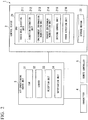
- FIG. 3 is a diagram showing a functional configuration of the transmitter according to an embodiment of the present invention.
- the transmitter 4 includes a sensor 41, a wireless communication unit 42, and a CPU 43.
- the sensor 41 is a sensor group for measuring the air conditioning environment (temperature, humidity, and the like) in the vicinity of the transmitter 4 and includes, for example, a temperature sensor, a humidity sensor, and the like.
- the wireless communication unit 42 is a dedicated IC chip mounted for performing wireless communication using a radio wave of a predetermined frequency band.
- the wireless communication unit 42 is an IC chip for transmitting and receiving the radio wave using Bluetooth (registered trademark) technology.
- the CPU 43 is a processor that is responsible for the overall operation of the transmitter 4, and is operated according to a predetermined program to function as a sensor information acquisition unit 431 and a radio wave transmission-processing unit 432.
- the sensor information acquisition unit 431 acquires the "environment information" indicating the air conditioning environment (temperature, humidity) in the vicinity of the transmitter 4 from the sensor 41 at every predetermined measurement time (for example, one minute).
- the radio wave transmission-processing unit 432 radiates the radio wave in which the "transmitter ID" that is set in the transmitter 4 in advance and the "environment information" acquired by the sensor information acquisition unit 431 are superimposed at every predetermined transmission time (for example, one minute).
- FIG. 4 is a flowchart showing an example of a process of the control device according to an embodiment of the present invention.
- the radio wave detection unit 211 of the control device 2 determines whether or not the reception unit 33 provided in the air conditioning indoor unit 3 has received the radio wave radiated from the transmitter 4 (step S10)
- the direction estimation unit 212 estimates the "transmitter direction” or the "transmitter position" of the transmitter 4 that is a transmission source of the radio wave (step S11).
- the direction estimation unit 212 calculates distances between each of the reception units 33 and the transmitter 4, on the basis of intensities of the radio waves received by each of the two reception units 33. In addition, the direction estimation unit 212 estimates the two-dimensional position (horizontal direction position) that satisfies the two distances in space, that is, the "transmitter direction" indicating the direction in which the transmitter 4 is disposed.
- the direction estimation unit 212 is able to further estimate the position in a height direction of the transmitter 4 on the basis of the intensities of the radio waves received by each of the reception units 33. That is, the direction estimation unit 212 further estimates the "transmitter position" that is the three-dimensional position of the transmitter 4 in the space, on the basis of the intensities of the radio waves received by each of the three or more reception units 33.
- the radio wave detection unit 211 sequentially detects the radio wave radiated from the transmitter 4 at every predetermined transmission time, but the present invention is not limited thereto. In alternative embodiments, when the radio wave detection unit 211 detects that the position of the transmitter 4 is changed, the radio wave detection unit 211 may detect the radio wave.
- a time when detecting that the position of the transmitter 4 is changed means, for example, a time when the radio wave intensity of the received radio wave is changed.
- the environment information acquisition unit 213 acquires the "transmitter ID” and the "environment information” included in the radio wave detected by the radio wave detection unit 211 (step S12).
- the environment information acquisition unit 213 stores the acquired "transmitter ID” and "environment information” in the storage medium 22 as “transmitter information D10 ( FIG. 5 )".
- FIG. 5 is a diagram showing an example of the transmitter information according to an embodiment of the present invention.
- the transmitter information D10 is information in which the "transmitter ID” capable of specifying the transmitter 4 that is the transmission source of the radio wave, the "environment information” indicating the air conditioning environment (temperature, humidity, and the like) in the vicinity of the transmitter 4, and the "transmitter direction” or the “transmitter position” of the transmitter 4 estimated by the direction estimation unit 212 are associated with each other.
- the transmitter information D10 is stored in the storage medium 22 for each of the transmitters.
- the required environment acquisition unit 214 acquires the "required environment setting" indicating the air conditioning environment requested by the user.
- the required environment acquisition unit 214 stores the "required environment setting" that is input by the user in advance through the remote controller 5 in the storage medium 22, and reads and acquires the latest "required environment setting" from the storage medium 22.
- the driving control unit 215 performs driving control of the air conditioning indoor unit 3 so that the air conditioning environment ("environment information") in the "transmitter direction” or the “transmitter position” of the transmitter 4 satisfies the "required environment setting" (step S14).
- the user has disposed the transmitter 4 in a baby bed where a baby is present as in the example of FIG. 1 .
- the user inputs the "required environment setting" that specifies temperature, humidity, and the like, which allow the baby to comfortably stay through the remote controller 5.
- the driving control unit 215 transmits a control command for changing a control amount of the fan 31 to the air conditioning indoor unit 3 so that the temperature, the humidity, and the like in the vicinity of the baby bed where the transmitter 4 is disposed is close to the "required environment setting" as much as possible.
- the user may think that the user does not want an airflow to directly blow towards the baby.
- the user may dispose different transmitters 4 to each of a position where the baby is present (baby bed) and a position where the adult is present and may input the "required environment setting" in which the airflow direction is designated so that the airflow only directly blows towards the adult.
- the driving control unit 215 transmits a control command for controlling the louver 32 to the air conditioning indoor unit 3 so that the airflow is not transmitted toward the transmitter 4 disposed at the baby bed and the airflow is transmitted toward the transmitter 4 disposed at the position where the adult is present.
- the driving control unit 215 is able to allow the air conditioning environment in the "transmitter direction" or the “transmitter position" of the transmitter 4 to be close to the environment according to the "required environment setting" requested by the user.
- the radio wave detection unit 211 determines whether or not a predetermined waiting time (for example, three minutes) has elapsed (step S15).
- the radio wave detection unit 211 determines that the error in which the radio wave is not able to be radiated has occurred in the transmitter 4, and transmits a control command for notifying the air conditioning indoor unit 3 of the error (step S16). Then, the air conditioning indoor unit 3 notifies the user through the notification unit 34 that the error has occurred in the transmitter 4.
- step S15 NO
- the radio wave detection unit 211 returns to step S10.
- FIG. 6 is a flowchart showing an example of a process of the transmitter according to an embodiment of the present invention. As shown in FIG. 6 , the transmitter 4 determines whether or not a predetermined transmission time (for example, one minute) has passed (step S20).
- a predetermined transmission time for example, one minute
- the transmitter 4 acquires the "environment information" indicating the air conditioning environment (temperature, humidity, and the like) in the vicinity of the transmitter 4 from the sensor 41 (step S21).
- the transmitter 4 radiates the radio wave in which the "transmitter ID” that is set in the transmitter 4 in advance and the "environment information” acquired in step S21 are superimposed (step S22).
- step S20 NO
- the transmitter 4 returns to step S20.
- the transmitter 4 periodically radiates the radio wave capable of estimating the "transmitter direction” or the “transmitter position” of the transmitter 4 and capable of acquiring the "environment information" in the vicinity of the transmitter 4, by repeatedly executing the above-described processes during operation.
- FIG. 6 shows an example in which the transmitter 4 radiates the radio wave every time the predetermined transmission time elapses, but the present invention is not limited thereto.
- the transmitter 4 may radiate the radio wave when the position of the transmitter 4 changes.
- the sensor 41 of the transmitter 4 may have an acceleration sensor, and the radio wave transmission-processing unit 432 may radiate the radio wave when the acceleration sensor detects a movement of the transmitter 4.
- FIG. 7 is a diagram showing an example of a hardware configuration of the control device and the transmitter according to an embodiment of the present invention.
- a computer 900 includes a CPU 901, a main storage device 902, an auxiliary storage device 903, and an interface 904.
- the control device 2 and the transmitter 4 described above are mounted on the computer 900.
- the operations of each of the processing units described above are stored in the auxiliary storage device 903 in a form of a program.
- the CPU 901 reads the program from the auxiliary storage device 903, develops the program in the main storage device 902, and executes the above-described process according to the program.
- the CPU 901 secures a storage region used by the control device 2 and the transmitter 4 for various processes in the main storage device 902.
- the CPU 901 secures a storage region for storing data under a process in the auxiliary storage device 903.
- auxiliary storage device 903 may include a hard disk drive (HDD), a solid-state drive (SSD), a magnetic disk, a magneto-optical disk, a compact disc read-only memory (CD-ROM), a digital versatile disc read-only memory (DVD-ROM), a semiconductor memory, and the like.
- the auxiliary storage device 903 may be an internal medium directly connected to a bus of the computer 900 or may be an external medium connected to the computer 900 through an interface 904 or a communication line.
- the computer 900 receiving the delivery may develop the program in the main storage device 902 and execute the process described above.
- the auxiliary storage device 903 is a non-transitory tangible storage medium.
- the program may be for realizing a part of the above-described function.
- the program may be a so-called difference file (difference program) that realizes the above-described function by a combination with another program that is stored in the auxiliary storage device 903 in advance.
- the control device 2 of the air conditioning system 1 of the present embodiment is the control device 2 that controls the air conditioning indoor unit 3.
- the control device 2 includes the radio wave detection unit 211 configured to detect the radio waves radiated from the transmitter 4 through at least two reception units 33 provided in the air conditioning indoor unit 3, the direction estimation unit 212 configured to estimate the "transmitter direction" indicating the direction in which the transmitter 4 is disposed on the basis of the radio waves received by each of the reception units 33, the environment information acquisition unit 213 configured to acquire the "environment information” indicating the air conditioning environment in the "transmitter direction", which is included in the radio waves, the required environment acquisition unit 214 configured to acquire the "required environment setting" requested by the user, and the driving control unit 215 configured to control the air conditioning indoor unit 3 so that the air conditioning environment in the "transmitter direction" satisfies the "required environment setting".
- the control device 2 is capable of adjusting the air conditioning environment in the direction in which the transmitter 4 is disposed according to an intention of the user by disposing the transmitter 4 in a place where the user preferentially wishes to adjust the air conditioning environment, it is possible to greatly improve comfort of the user.
- the reception units 33 are disposed at different positions in the horizontal direction, and the direction estimation unit 212 estimates the "transmitter direction" on the basis of the intensities of the radio waves received by each of the reception units 33 from the transmitter 4.
- the direction estimation unit 212 is capable of accurately estimating the direction in which the transmitter 4 is disposed (two-dimensional position).
- the air conditioning indoor unit 3 is provided with three or more reception units 33, and the direction estimation unit 212 further estimates the "transmitter position" indicating the position of the transmitter 4 on the basis of the intensities of the radio waves received by each of the three or more reception units 33 from the transmitter 4.
- the control device 2 is capable of estimating the "transmitter position" indicating the three-dimensional position where the transmitter 4 is disposed and adjust the air conditioning environment in the vicinity of the "transmitter position” according to the intention of the user.
- the control device 2 is capable of further improve the comfort of the user.
- the direction estimation unit 212 estimates the "transmitter direction” or the “transmitter position” of each of the plurality of transmitter 4, the required environment acquisition unit 214 acquires the different “required environment settings" for each of the transmitters, and the driving control unit 215 controls the air conditioning indoor unit 3 so that the air conditioning environment in "transmitter direction” or the “transmitter position” of each of the plurality of transmitter 4 satisfies the "required environment settings" for each of the transmitters.
- the control device 2 is capable of appropriately adjusting a range where the airflow blows, for example, the airflow blows in a certain direction (position) and the airflow does not blow in another direction (position), etc., according to a preference of each of a plurality of users. Accordingly, the control device 2 is capable of improving the comfort of each of the plurality of users.
- control device 2 further includes the error detection unit 216 configured to detect the occurrence of the error in the transmitter 4 in a case where the radio wave from the transmitter 4 is not received even after a predetermined waiting time has elapsed.
- control device 2 is capable of detecting that the radio wave is not able to be radiated due to, for example, a failure of the transmitter 4 or battery exhaustion.
- control device 2 is able to quickly allow the user to recognize the failure of the transmitter 4 or the battery exhaustion by notifying the user of the detected error through the notification unit 34 of the air conditioning indoor unit 3.
- the driving control unit 215 is capable of performing the driving control of the air conditioning indoor unit 3 while sequentially checking whether the air conditioning environment in the vicinity of the transmitter 4 is close to the "required environment setting". According to the above configuration, the driving control unit 215 is capable of adjusting the air conditioning environment in the vicinity of the transmitter 4 with high precision so that the air conditioning environment satisfies the "required environment setting" as much as possible. Thus, the control device 2 is capable of providing a more comfortable air conditioning environment closer to the request of the user.
- the remote controller 5 may include each functional part of the transmitter 4.
- the remote controller 5 radiates the radio wave in which the "required environment setting" received from the user is superimposed to the reception unit 33 of the air conditioning indoor unit 3, by using the technology such as Bluetooth (registered trademark).
Landscapes
- Engineering & Computer Science (AREA)
- Chemical & Material Sciences (AREA)
- Combustion & Propulsion (AREA)
- Mechanical Engineering (AREA)
- General Engineering & Computer Science (AREA)
- Signal Processing (AREA)
- Human Computer Interaction (AREA)
- Physics & Mathematics (AREA)
- Fuzzy Systems (AREA)
- Mathematical Physics (AREA)
- Air Conditioning Control Device (AREA)
Abstract
A control device (2) includes a radio wave detection unit (211) configured to detect radio waves radiated from a transmitter (4) through at least two reception units (33) provided in the air conditioning indoor unit (3), a direction estimation unit (212) configured to estimate a transmitter direction indicating a direction in which the transmitter (4) is disposed on the basis of the radio waves received by each of the reception units (33), an environment information acquisition unit (213) configured to acquire environment information indicating an air conditioning environment in the transmitter direction, which is included in the radio waves, a required environment acquisition unit (214) configured to acquire a required environment setting requested by a user, and a driving control unit (215) configured to control the air conditioning indoor unit (3) so that the air conditioning environment in the transmitter direction satisfies the required environment setting.
Description
- The present invention relates to a control device, an air conditioning system, a control method, and a program.
- An air conditioning system of the related art, which controls a temperature, a humidity, an airflow direction, and the like of a room according to characteristics of a user in order to improve comfort, is known (refer to, for example, Japanese Unexamined Patent Application, First Publication No.
2003-50040 - In addition, for the purpose of further improving comfort, an air conditioning system that detects a position of the user in a room and utilizes the position of the user for output control of an indoor unit and airflow direction control is conceivable.
- In the air conditioning system of the related art, the position of the user is detected by using a sensor (human sensor, temperature sensor, and the like) built into the indoor unit. However, according to the related art, in a case where an obstacle is present between the indoor unit and the user, or in a case where it is recognized that a plurality of users overlap, the position of the user may not be able to be correctly recognized, and it may be difficult to control the air conditioning system such that there is an air conditioning environment intended by the user.
- The present invention provides a control device, an air conditioning system, a control method, and a program capable of allowing adjustment of an air conditioning environment in a specific place to that intended by a user even in a case where an obstacle is present.
- According to a first aspect of the present invention, a control device that controls an air conditioning indoor unit includes a radio wave detection unit configured to detect radio waves radiated from a transmitter through at least two reception units provided in the air conditioning indoor unit, a direction estimation unit configured to estimate a transmitter direction indicating a direction in which the transmitter is disposed on the basis of the radio waves received by each of the reception units, an environment information acquisition unit configured to acquire environment information indicating an air conditioning environment in the transmitter direction, which is included in the radio waves, a required environment acquisition unit configured to acquire a required environment setting requested by a user, and a driving control unit configured to control the air conditioning indoor unit so that the air conditioning environment in the transmitter direction satisfies the required environment setting.
- According to the above configuration, for example, even in a case where an obstacle is present between the air conditioning indoor unit and the transmitter, it is possible to estimate the transmitter direction in which the transmitter is disposed. Thus, since the control device is capable of adjusting the air conditioning environment in the direction in which the transmitter is disposed according to an intention of the user by disposing the transmitter in a place where the user preferentially wishes to adjust the air conditioning environment, it is possible to greatly improve comfort of the user.
- According to a second aspect of the present invention, in the control device of the first aspect, the reception units are disposed at different positions in a horizontal direction, and the direction estimation unit estimates the transmitter direction on the basis of intensities of the radio waves received by each of the reception units from the transmitter.
- According to the above configuration, the direction estimation unit is capable of accurately estimating the direction in which the transmitter is disposed.
- According to a third aspect of the present invention, in the control device of the first or second aspect, the air conditioning indoor unit is provided with three or more reception units, and the direction estimation unit further estimates a transmitter position indicating a position of the transmitter on the basis of intensities of the radio waves received by each of the three or more reception units from the transmitter.
- According to the above configuration, the control device is capable of estimating the position where the transmitter is disposed and adjust the air conditioning environment in the vicinity of the transmitter position according to the intention of the user. Thus, the control device is capable of further improving the comfort of the user.
- According to a fourth aspect of the present invention, in the control device of the first to third aspects, the direction estimation unit estimates the transmitter direction indicating a direction in which each of a plurality of transmitters is disposed, the required environment acquisition unit acquires different required environment settings for each of the transmitters, and the driving control unit controls the air conditioning indoor unit so that the air conditioning environment in the transmitter direction of each of the plurality of transmitters satisfies the required environment settings for each of the transmitters.
- According to the above configuration, by disposing the transmitter in each of a plurality of places where the user wishes to adjust the air conditioning environment, the control device is capable of appropriately adjusting a range where the airflow blows, for example, the airflow blows in a certain direction and the airflow does not blow in another direction, etc., according to a preference of each of a plurality of users. Accordingly, the control device is capable of improving the comfort of each of the plurality of users.
- According to a fifth aspect of the present invention, the control device of any one of the first to fourth aspects further includes an error detection unit configured to detect the occurrence of an error in the transmitter in a case where the radio wave from the transmitter is not received even after a predetermined waiting time has elapsed.
- According to the above configuration, the control device is capable of detecting that the radio wave is not capable of being radiated due to, for example, a failure of the transmitter or battery exhaustion.
- According to a sixth aspect of the present invention, an air conditioning system includes a transmitter configured to radiate a radio wave, an air conditioning indoor unit having at least two reception units that receive the radio waves radiated from the transmitter, and a control device of any one of the first to fifth aspects.
- According to a seventh aspect of the present invention, a control method for controlling an air conditioning indoor unit includes a radio wave detection step of detecting radio waves radiated from a transmitter through at least two reception units provided in the air conditioning indoor unit, a direction estimation step of estimating a transmitter direction indicating a direction in which the transmitter is disposed on the basis of the radio waves received by each of the reception units, an environment information acquisition step of acquiring environment information indicating an air conditioning environment in the transmitter direction, which is included in the radio waves, a required environment acquisition step of acquiring a required environment setting requested by a user, and an operation control step of controlling the air conditioning indoor unit so that the air conditioning environment in the transmitter direction satisfies the required environment setting.
- According to an eighth aspect of the present invention, a program causes a computer of a control device that controls an air conditioning indoor unit to function and execute a radio wave detection step of detecting radio waves radiated from a transmitter through at least two reception units provided in the air conditioning indoor unit, a direction estimation step of estimating a transmitter direction indicating a direction in which the transmitter is disposed on the basis of the radio waves received by each of the reception units, an environment information acquisition step of acquiring environment information indicating an air conditioning environment in the transmitter direction, which is included in the radio waves, a required environment acquisition step of acquiring a required environment setting requested by a user, and an operation control step of controlling the air conditioning indoor unit so that the air conditioning environment in the transmitter direction satisfies the required environment setting.
- According to the control device, the air conditioning system, the control method, and the program as described above, it is possible to adjust a specific place to the air conditioning environment intended by the user even in a case where an obstacle is present.
-
-
FIG. 1 is a schematic diagram showing an overall configuration of an air conditioning system according to an embodiment of the present invention. -
FIG. 2 is a diagram showing a functional configuration of the air conditioning system according to the embodiment of the present invention. -
FIG. 3 is a diagram showing a functional configuration of a transmitter according to the embodiment of the present invention. -
FIG. 4 is a flowchart showing an example of a process of a control device according to the embodiment of the present invention. -
FIG. 5 is a diagram showing an example of transmitter information according to the embodiment of the present invention. -
FIG. 6 is a flowchart showing an example of a process of the transmitter according to the embodiment of the present invention. -
FIG. 7 is a diagram showing an example of a hardware configuration of the control device and the transmitter according to the embodiment of the present invention. - Hereinafter, an
air conditioning system 1 according to a first embodiment of the present invention will be described with reference toFIGS. 1 to 7 . - In the present embodiment, an aspect in which the
air conditioning system 1 is a home room air conditioner will be described as an example, but the present invention is not limited thereto. In alternative embodiment, theair conditioning system 1 may be a system provided in a space such as a large store, a factory, or the like where a large number of users are present. -
FIG. 1 is a schematic diagram showing an overall configuration of an air conditioning system according to an embodiment of the present invention. - As shown in
FIG. 1 , theair conditioning system 1 includes acontrol device 2, an air conditioningindoor unit 3, atransmitter 4, and aremote controller 5. - The
control device 2 receives a request for an air conditioning environment (temperature, humidity, air volume, airflow direction, and the like) (hereinafter also referred to as "required environment setting") from the user and controls the air conditioningindoor unit 3 such that the request is satisfied. - The air conditioning
indoor unit 3 is installed on a wall surface, a ceiling, or the like of a space (room) in which the user is present, and performs various operations for adjusting the air conditioning environment in the space according to a control command by thecontrol device 2. AlthoughFIG. 1 shows an example in which theair conditioning system 1 includes one air conditioningindoor unit 3, the present invention is not limited thereto. In alternative embodiments, theair conditioning system 1 may include a plurality of air conditioningindoor units 3, and onecontrol unit 2 may control the plurality of air conditioningindoor units 3. As shown inFIG. 1 , the air conditioningindoor unit 3 includes afan 31 capable of adjusting the air volume, alouver 32 capable of adjusting the airflow direction, at least tworeception units 33 capable of receiving radio waves from thetransmitter 4, and anotification unit 34 that notifies the user of the occurrence of an error. - The
reception units 33 are each disposed at different positions in a horizontal direction. For example, as shown inFIG. 1 , tworeception units 33 are each disposed at opposite ends in the horizontal direction of the air conditioningindoor unit 3. AlthoughFIG. 1 shows an example in which the air conditioningindoor unit 3 includes two of thereception units 33, the present invention is not limited thereto. In alternative embodiments, the air conditioningindoor unit 3 may include three ormore reception units 33. - The
notification unit 34 is a display device such as a liquid crystal display or an LED. When thenotification unit 34 detects an error such that thereception unit 33 is not capable of receiving the radio wave from thetransmitter 4, thenotification unit 34 notifies the user of the detection of the error. In addition, thenotification unit 34 may be an output device that notifies detection of the error by voice. In addition, in the present embodiment, an aspect in which thenotification unit 34 is provided in the air conditioningindoor unit 3 is described as an example, but the present invention is not limited thereto. In alternative embodiments, thenotification unit 34 may be provided in theremote controller 5. - The
transmitter 4 is a terminal device disposed at a place where the user prefers to adjust the air conditioning environment. For example, as shown inFIG. 1 , in a case where a plurality of users (adult and baby) are present in one space, it is conceivable that the user may request an air conditioning environment in which the baby is able to remain in comfort. In this case, the user is able to preferentially adjust the air conditioning environment in the vicinity of a baby bed by disposing thetransmitter 4 in the baby bed where the baby is present. - In addition, the
transmitter 4 radiates radio waves including the air conditioning environment (temperature, humidity, and the like) at the position where thetransmitter 4 is disposed at every predetermined transmission time. - The
transmitter 4 radiates a radio wave having a frequency band of at least 300 GHz or less such that the radio wave transmits through an obstacle disposed between thereceiver 33 provided in the air conditioningindoor unit 3 and thetransmitter 4. More preferably, thetransmitter 4 radiates a radio wave of a frequency band of 300 MHz to 300 GHz (so-called microwave). In the present embodiment, an aspect in which thetransmitter 4 radiates a radio wave of a frequency band of 2.4 GHz using Bluetooth (registered trademark) technology, particularly Bluetooth Low Energy will be described as an example. - Although
FIG. 1 shows an example in which only onetransmitter 4 is disposed in the space, the present invention is not limited thereto. In another embodiment, a plurality oftransmitters 4 may be disposed. - The
remote controller 5 receives an input operation of the "required environment setting" from the user and transmits the input operation to thecontrol device 2. The "required environment setting" is a setting value of the air conditioning environment requested by the user, and includes, for example, a temperature, humidity, air volume, airflow direction, and the like. In addition, in a case where a plurality oftransmitters 4 are disposed, theremote controller 5 may receive different "required environment settings" for each of thetransmitters 4. - For example, the
remote controller 5 transmits the "required environment setting" to thecontrol device 2 through a light reception unit (not shown) provided in the air conditioningindoor unit 3 by infrared communication similarly to the air conditioning system of the related art. In addition, in alternative embodiments, theremote controller 5 may be wired to the air conditioningindoor unit 3. -
FIG. 2 is a diagram showing a functional configuration of the air conditioning system according to an embodiment of the present invention. - As shown in
FIG. 2 , thecontrol device 2 of theair conditioning system 1 has aCPU 21 and astorage medium 22. - The
CPU 21 is a processor that is responsible for the overall operation of thecontrol device 2 and operates according to a predetermined program, to function as a radiowave detection unit 211, adirection estimation unit 212, an environmentinformation acquisition unit 213, a requiredenvironment acquisition unit 214, a drivingcontrol unit 215, and anerror detection unit 216. - The radio
wave detection unit 211 detects the radio wave radiated from thetransmitter 4 through thereception unit 33 provided in the air conditioningindoor unit 3. - Note that the radio wave radiated from the
transmitter 4 includes a "transmitter ID" capable of specifying thetransmitter 4 and "environment information" indicating the air conditioning environment (temperature, humidity, and the like) at the position of thetransmitter 4. - The
direction estimation unit 212 estimates a "transmitter direction" indicating a direction in which thetransmitter 4 is disposed (a two-dimensional position in the horizontal direction) or "transmitter position" indicating a three-dimensional position, on the basis of the radio waves received by each of thereception units 33 provided in the air conditioningindoor unit 3. - In a case where a plurality of
transmitters 4 are disposed in the space, thedirection estimation unit 212 specifies thetransmitter 4 associated with the radio wave by the "transmitter ID" included in the radio wave, and estimates the "transmitter direction" or the "transmitter position" of each of thetransmitters 4. - The environmental
information acquisition unit 213 acquires "environment information" included in the radio wave radiated from thetransmitter 4. Therefore, the environmentinformation acquisition unit 213 acquires the environmental information indicating the air conditioning environment (temperature, humidity, and the like) in the "transmitter direction (two-dimensional position)" or the "transmitter position (three-dimensional position)" of thetransmitter 4. - The required
environment acquisition unit 214 acquires the "required environment setting" requested by the user. - The driving
control unit 215 controls the air conditioningindoor unit 3 so that the air conditioning environment in the "transmitter direction" or the "transmitter position" of thetransmitter 4 satisfies the "required environment setting". - In addition, in a case where a plurality of
transmitters 4 are disposed, the drivingcontrol unit 215 controls the air conditioningindoor unit 3 so that the air conditioning environment in the "transmitter direction" or the "transmitter position" of each of the plurality oftransmitters 4 satisfies the "required environment setting" for each of thetransmitters 4. - The
error detection unit 216 detects the occurrence of an error in thetransmitter 4 in a case where a period during which the radio wave is not received from thetransmitter 4 continues for a predetermined waiting time (for example, three minutes) or more. - In addition, the
error detection unit 216 notifies the user of the occurrence of the error through thenotification unit 34 of the air conditioningindoor unit 3. Therefore, for example, it is possible to notify the user that the radio wave is not able to be radiated by detecting that the radio wave is not able to be radiated due to failure of thetransmitter 4, battery exhaustion, or the like. - The "required environment setting" acquired by the required
environment acquisition unit 214 is stored in thestorage medium 22. In addition, the "transmitter direction" or the "transmitter position" of thetransmitter 4 estimated by thedirection estimation unit 212 and the "environment information" acquired by the environmentinformation acquisition unit 213 may be stored in thestorage medium 22. -
FIG. 3 is a diagram showing a functional configuration of the transmitter according to an embodiment of the present invention. - As shown in
FIG. 3 , thetransmitter 4 includes asensor 41, awireless communication unit 42, and aCPU 43. - The
sensor 41 is a sensor group for measuring the air conditioning environment (temperature, humidity, and the like) in the vicinity of thetransmitter 4 and includes, for example, a temperature sensor, a humidity sensor, and the like. - The
wireless communication unit 42 is a dedicated IC chip mounted for performing wireless communication using a radio wave of a predetermined frequency band. In the present embodiment, as described above, thewireless communication unit 42 is an IC chip for transmitting and receiving the radio wave using Bluetooth (registered trademark) technology. - The
CPU 43 is a processor that is responsible for the overall operation of thetransmitter 4, and is operated according to a predetermined program to function as a sensorinformation acquisition unit 431 and a radio wave transmission-processing unit 432. - The sensor
information acquisition unit 431 acquires the "environment information" indicating the air conditioning environment (temperature, humidity) in the vicinity of thetransmitter 4 from thesensor 41 at every predetermined measurement time (for example, one minute). - The radio wave transmission-
processing unit 432 radiates the radio wave in which the "transmitter ID" that is set in thetransmitter 4 in advance and the "environment information" acquired by the sensorinformation acquisition unit 431 are superimposed at every predetermined transmission time (for example, one minute). -
FIG. 4 is a flowchart showing an example of a process of the control device according to an embodiment of the present invention. - As shown in
FIG. 4 , the radiowave detection unit 211 of thecontrol device 2 determines whether or not thereception unit 33 provided in the air conditioningindoor unit 3 has received the radio wave radiated from the transmitter 4 (step S10) - In a case where the radio
wave detection unit 211 detects that the radio wave from thetransmitter 4 is received (step S10: YES), thedirection estimation unit 212 estimates the "transmitter direction" or the "transmitter position" of thetransmitter 4 that is a transmission source of the radio wave (step S11). - As shown in
FIG. 1 , in a case where the tworeception units 33 are provided in the air conditioningindoor unit 3, thedirection estimation unit 212 calculates distances between each of thereception units 33 and thetransmitter 4, on the basis of intensities of the radio waves received by each of the tworeception units 33. In addition, thedirection estimation unit 212 estimates the two-dimensional position (horizontal direction position) that satisfies the two distances in space, that is, the "transmitter direction" indicating the direction in which thetransmitter 4 is disposed. - In addition, in a case where three or
more reception units 33 are provided in the air conditioning indoor unit, thedirection estimation unit 212 is able to further estimate the position in a height direction of thetransmitter 4 on the basis of the intensities of the radio waves received by each of thereception units 33. That is, thedirection estimation unit 212 further estimates the "transmitter position" that is the three-dimensional position of thetransmitter 4 in the space, on the basis of the intensities of the radio waves received by each of the three ormore reception units 33. - In the present embodiment, the radio
wave detection unit 211 sequentially detects the radio wave radiated from thetransmitter 4 at every predetermined transmission time, but the present invention is not limited thereto. In alternative embodiments, when the radiowave detection unit 211 detects that the position of thetransmitter 4 is changed, the radiowave detection unit 211 may detect the radio wave. A time when detecting that the position of thetransmitter 4 is changed means, for example, a time when the radio wave intensity of the received radio wave is changed. - Next, the environment
information acquisition unit 213 acquires the "transmitter ID" and the "environment information" included in the radio wave detected by the radio wave detection unit 211 (step S12). - At this time, the environment
information acquisition unit 213 stores the acquired "transmitter ID" and "environment information" in thestorage medium 22 as "transmitter information D10 (FIG. 5 )". -
FIG. 5 is a diagram showing an example of the transmitter information according to an embodiment of the present invention. - As shown in
FIG. 5 , the transmitter information D10 is information in which the "transmitter ID" capable of specifying thetransmitter 4 that is the transmission source of the radio wave, the "environment information" indicating the air conditioning environment (temperature, humidity, and the like) in the vicinity of thetransmitter 4, and the "transmitter direction" or the "transmitter position" of thetransmitter 4 estimated by thedirection estimation unit 212 are associated with each other. - In a case where a plurality of
transmitters 4 are disposed, the transmitter information D10 is stored in thestorage medium 22 for each of the transmitters. - Next, the required
environment acquisition unit 214 acquires the "required environment setting" indicating the air conditioning environment requested by the user. - At this time, the required
environment acquisition unit 214 stores the "required environment setting" that is input by the user in advance through theremote controller 5 in thestorage medium 22, and reads and acquires the latest "required environment setting" from thestorage medium 22. - Next, the driving
control unit 215 performs driving control of the air conditioningindoor unit 3 so that the air conditioning environment ("environment information") in the "transmitter direction" or the "transmitter position" of thetransmitter 4 satisfies the "required environment setting" (step S14). - For example, it is assumed that the user has disposed the
transmitter 4 in a baby bed where a baby is present as in the example ofFIG. 1 . At this time, the user inputs the "required environment setting" that specifies temperature, humidity, and the like, which allow the baby to comfortably stay through theremote controller 5. Then, the drivingcontrol unit 215 transmits a control command for changing a control amount of thefan 31 to the air conditioningindoor unit 3 so that the temperature, the humidity, and the like in the vicinity of the baby bed where thetransmitter 4 is disposed is close to the "required environment setting" as much as possible. In addition, there is a possibility that the user may think that the user does not want an airflow to directly blow towards the baby. In this case, the user may disposedifferent transmitters 4 to each of a position where the baby is present (baby bed) and a position where the adult is present and may input the "required environment setting" in which the airflow direction is designated so that the airflow only directly blows towards the adult. In this case, the drivingcontrol unit 215 transmits a control command for controlling thelouver 32 to the air conditioningindoor unit 3 so that the airflow is not transmitted toward thetransmitter 4 disposed at the baby bed and the airflow is transmitted toward thetransmitter 4 disposed at the position where the adult is present. - Therefore, the driving
control unit 215 is able to allow the air conditioning environment in the "transmitter direction" or the "transmitter position" of thetransmitter 4 to be close to the environment according to the "required environment setting" requested by the user. - In addition, in a case where the
reception unit 33 has not detected the reception of the radio wave from the transmitter 4 (step S10: NO), the radiowave detection unit 211 determines whether or not a predetermined waiting time (for example, three minutes) has elapsed (step S15). - In a case where the radio
wave detection unit 211 has not detected the reception of the radio wave even after the predetermined waiting time has elapsed since a reception of a previous radio wave (step S15: YES), the radiowave detection unit 211 determines that the error in which the radio wave is not able to be radiated has occurred in thetransmitter 4, and transmits a control command for notifying the air conditioningindoor unit 3 of the error (step S16). Then, the air conditioningindoor unit 3 notifies the user through thenotification unit 34 that the error has occurred in thetransmitter 4. - On the other hand, in a case where the predetermined waiting time has not elapsed (step S15: NO), the radio
wave detection unit 211 returns to step S10. -
FIG. 6 is a flowchart showing an example of a process of the transmitter according to an embodiment of the present invention. As shown inFIG. 6 , thetransmitter 4 determines whether or not a predetermined transmission time (for example, one minute) has passed (step S20). - In a case where the predetermined transmission time has elapsed (step S20: YES), the
transmitter 4 acquires the "environment information" indicating the air conditioning environment (temperature, humidity, and the like) in the vicinity of thetransmitter 4 from the sensor 41 (step S21). - Next, the
transmitter 4 radiates the radio wave in which the "transmitter ID" that is set in thetransmitter 4 in advance and the "environment information" acquired in step S21 are superimposed (step S22). - In addition, in a case where the predetermined transmission time has elapsed (step S20: NO), the
transmitter 4 returns to step S20. - The
transmitter 4 periodically radiates the radio wave capable of estimating the "transmitter direction" or the "transmitter position" of thetransmitter 4 and capable of acquiring the "environment information" in the vicinity of thetransmitter 4, by repeatedly executing the above-described processes during operation. -
FIG. 6 shows an example in which thetransmitter 4 radiates the radio wave every time the predetermined transmission time elapses, but the present invention is not limited thereto. In another embodiment, thetransmitter 4 may radiate the radio wave when the position of thetransmitter 4 changes. In this case, for example, thesensor 41 of thetransmitter 4 may have an acceleration sensor, and the radio wave transmission-processing unit 432 may radiate the radio wave when the acceleration sensor detects a movement of thetransmitter 4. -
FIG. 7 is a diagram showing an example of a hardware configuration of the control device and the transmitter according to an embodiment of the present invention. - Hereinafter, an example of the hardware configuration of the
control device 2 and thetransmitter 4 will be described with reference toFIG. 7 . - As shown in
FIG. 7 , acomputer 900 includes aCPU 901, amain storage device 902, anauxiliary storage device 903, and aninterface 904. - The
control device 2 and thetransmitter 4 described above are mounted on thecomputer 900. In addition, the operations of each of the processing units described above are stored in theauxiliary storage device 903 in a form of a program. TheCPU 901 reads the program from theauxiliary storage device 903, develops the program in themain storage device 902, and executes the above-described process according to the program. In addition, in accordance with the program, theCPU 901 secures a storage region used by thecontrol device 2 and thetransmitter 4 for various processes in themain storage device 902. In addition, in accordance with the program, theCPU 901 secures a storage region for storing data under a process in theauxiliary storage device 903. - Examples of the
auxiliary storage device 903 may include a hard disk drive (HDD), a solid-state drive (SSD), a magnetic disk, a magneto-optical disk, a compact disc read-only memory (CD-ROM), a digital versatile disc read-only memory (DVD-ROM), a semiconductor memory, and the like. Theauxiliary storage device 903 may be an internal medium directly connected to a bus of thecomputer 900 or may be an external medium connected to thecomputer 900 through aninterface 904 or a communication line. In addition, in a case where the program is delivered to thecomputer 900 through the communication line, thecomputer 900 receiving the delivery may develop the program in themain storage device 902 and execute the process described above. In at least one embodiment, theauxiliary storage device 903 is a non-transitory tangible storage medium. - In addition, the program may be for realizing a part of the above-described function. Furthermore, the program may be a so-called difference file (difference program) that realizes the above-described function by a combination with another program that is stored in the
auxiliary storage device 903 in advance. - As described above, the
control device 2 of theair conditioning system 1 of the present embodiment is thecontrol device 2 that controls the air conditioningindoor unit 3. Thecontrol device 2 includes the radiowave detection unit 211 configured to detect the radio waves radiated from thetransmitter 4 through at least tworeception units 33 provided in the air conditioningindoor unit 3, thedirection estimation unit 212 configured to estimate the "transmitter direction" indicating the direction in which thetransmitter 4 is disposed on the basis of the radio waves received by each of thereception units 33, the environmentinformation acquisition unit 213 configured to acquire the "environment information" indicating the air conditioning environment in the "transmitter direction", which is included in the radio waves, the requiredenvironment acquisition unit 214 configured to acquire the "required environment setting" requested by the user, and the drivingcontrol unit 215 configured to control the air conditioningindoor unit 3 so that the air conditioning environment in the "transmitter direction" satisfies the "required environment setting". According to the above configuration, for example, even in a case where an obstacle is present between the air conditioningindoor unit 3 and thetransmitter 4, it is possible to estimate the "transmitter direction" in which thetransmitter 4 is disposed. Thus, since thecontrol device 2 is capable of adjusting the air conditioning environment in the direction in which thetransmitter 4 is disposed according to an intention of the user by disposing thetransmitter 4 in a place where the user preferentially wishes to adjust the air conditioning environment, it is possible to greatly improve comfort of the user. - In addition, the
reception units 33 are disposed at different positions in the horizontal direction, and thedirection estimation unit 212 estimates the "transmitter direction" on the basis of the intensities of the radio waves received by each of thereception units 33 from thetransmitter 4. - Therefore, the
direction estimation unit 212 is capable of accurately estimating the direction in which thetransmitter 4 is disposed (two-dimensional position). - In addition, the air conditioning
indoor unit 3 is provided with three ormore reception units 33, and thedirection estimation unit 212 further estimates the "transmitter position" indicating the position of thetransmitter 4 on the basis of the intensities of the radio waves received by each of the three ormore reception units 33 from thetransmitter 4. - According to the above configuration, the
control device 2 is capable of estimating the "transmitter position" indicating the three-dimensional position where thetransmitter 4 is disposed and adjust the air conditioning environment in the vicinity of the "transmitter position" according to the intention of the user. Thus, thecontrol device 2 is capable of further improve the comfort of the user. - In addition, the
direction estimation unit 212 estimates the "transmitter direction" or the "transmitter position" of each of the plurality oftransmitter 4, the requiredenvironment acquisition unit 214 acquires the different "required environment settings" for each of the transmitters, and the drivingcontrol unit 215 controls the air conditioningindoor unit 3 so that the air conditioning environment in "transmitter direction" or the "transmitter position" of each of the plurality oftransmitter 4 satisfies the "required environment settings" for each of the transmitters. - According to the above configuration, by disposing the
transmitter 4 in each of a plurality of places where the user wishes to adjust the air conditioning environment, thecontrol device 2 is capable of appropriately adjusting a range where the airflow blows, for example, the airflow blows in a certain direction (position) and the airflow does not blow in another direction (position), etc., according to a preference of each of a plurality of users. Accordingly, thecontrol device 2 is capable of improving the comfort of each of the plurality of users. - In addition, the
control device 2 further includes theerror detection unit 216 configured to detect the occurrence of the error in thetransmitter 4 in a case where the radio wave from thetransmitter 4 is not received even after a predetermined waiting time has elapsed. - According to the above configuration, the
control device 2 is capable of detecting that the radio wave is not able to be radiated due to, for example, a failure of thetransmitter 4 or battery exhaustion. - In addition, in a case where the failure of the
transmitter 4 or the battery exhaustion has occurred, thecontrol device 2 is able to quickly allow the user to recognize the failure of thetransmitter 4 or the battery exhaustion by notifying the user of the detected error through thenotification unit 34 of the air conditioningindoor unit 3. - In addition, since the environment
information acquisition unit 213 periodically acquires the "environment information" in the vicinity of thetransmitter 4, the drivingcontrol unit 215 is capable of performing the driving control of the air conditioningindoor unit 3 while sequentially checking whether the air conditioning environment in the vicinity of thetransmitter 4 is close to the "required environment setting". According to the above configuration, the drivingcontrol unit 215 is capable of adjusting the air conditioning environment in the vicinity of thetransmitter 4 with high precision so that the air conditioning environment satisfies the "required environment setting" as much as possible. Thus, thecontrol device 2 is capable of providing a more comfortable air conditioning environment closer to the request of the user. - In the embodiments, an example in which the
transmitter 4 and theremote controller 5 are different devices has been described, but the present invention is not limited thereto. In alternative embodiments, theremote controller 5 may include each functional part of thetransmitter 4. - In this case, similarly to the
transmitter 4, theremote controller 5 radiates the radio wave in which the "required environment setting" received from the user is superimposed to thereception unit 33 of the air conditioningindoor unit 3, by using the technology such as Bluetooth (registered trademark). - Even with such an aspect, it is possible to obtain the same advantageous effects as the above-described embodiment.
Claims (8)
- A control device that controls an air conditioning indoor unit, the control device comprising:a radio wave detection unit configured to detect radio waves radiated from a transmitter through at least two reception units provided in the air conditioning indoor unit;a direction estimation unit configured to estimate a transmitter direction indicating a direction in which the transmitter is disposed on the basis of the radio waves received by each of the reception units;an environment information acquisition unit configured to acquire environment information indicating an air conditioning environment in the transmitter direction, which is included in the radio waves;a required environment acquisition unit configured to acquire a required environment setting requested by a user; anda driving control unit configured to control the air conditioning indoor unit so that the air conditioning environment in the transmitter direction satisfies the required environment setting.
- The control device according to Claim 1,wherein the reception units are disposed at different positions in a horizontal direction, respectively, andthe direction estimation unit estimates the transmitter direction on the basis of intensities of the radio waves received by each of the reception units from the transmitter.
- The control device according to claim 1 or 2,wherein the air conditioning indoor unit is provided with three or more reception units, andthe direction estimation unit further estimates a transmitter position indicating a position of the transmitter on the basis of intensities of the radio waves received by each of the three or more reception units from the transmitter.
- The control device according to any one of claims 1 to 3,wherein the direction estimation unit estimates the transmitter direction indicating a direction in which each of a plurality of transmitters is disposed,the required environment acquisition unit acquires different required environment settings for each of the transmitters, andthe driving control unit controls the air conditioning indoor unit so that the air conditioning environment in the transmitter direction of each of the plurality of transmitters satisfies the required environment settings for each of the transmitters.
- The control device according to any one of claims 1 to 4, further comprising:
an error detection unit configured to detect the occurrence of an error in the transmitter in a case where the radio wave from the transmitter is not received even after a predetermined waiting time has elapsed. - An air conditioning system comprising:a transmitter configured to radiate a radio wave;an air conditioning indoor unit having at least two reception units that receive the radio waves radiated from the transmitter; anda control device according to any one of claims 1 to 5.
- A control method for controlling an air conditioning indoor unit, the control method comprising:a radio wave detection step of detecting radio waves radiated from a transmitter through at least two reception units provided in the air conditioning indoor unit;a direction estimation step of estimating a transmitter direction indicating a direction in which the transmitter is disposed on the basis of the radio waves received by each of the reception units;an environment information acquisition step of acquiring environment information indicating an air conditioning environment in the transmitter direction, which is included in the radio waves;a required environment acquisition step of acquiring a required environment setting requested by a user; andan operation control step of controlling the air conditioning indoor unit so that the air conditioning environment in the transmitter direction satisfies the required environment setting.
- A program for causing a computer of a control device that controls an air conditioning indoor unit to function and execute:a radio wave detection step of detecting radio waves radiated from a transmitter through at least two reception units provided in the air conditioning indoor unit;a direction estimation step of estimating a transmitter direction indicating a direction in which the transmitter is disposed on the basis of the radio waves received by each of the reception units;an environment information acquisition step of acquiring environment information indicating an air conditioning environment in the transmitter direction, which is included in the radio waves;a required environment acquisition step of acquiring a required environment setting requested by a user; andan operation control step of controlling the air conditioning indoor unit so that the air conditioning environment in the transmitter direction satisfies the required environment setting.
Applications Claiming Priority (1)
| Application Number | Priority Date | Filing Date | Title |
|---|---|---|---|
| JP2018067835A JP7136575B2 (en) | 2018-03-30 | 2018-03-30 | Air conditioning system and control method |
Publications (1)
| Publication Number | Publication Date |
|---|---|
| EP3546844A1 true EP3546844A1 (en) | 2019-10-02 |
Family
ID=65598568
Family Applications (1)
| Application Number | Title | Priority Date | Filing Date |
|---|---|---|---|
| EP19159481.1A Withdrawn EP3546844A1 (en) | 2018-03-30 | 2019-02-26 | Control device, air conditioning system, control method, and program |
Country Status (3)
| Country | Link |
|---|---|
| EP (1) | EP3546844A1 (en) |
| JP (1) | JP7136575B2 (en) |
| AU (1) | AU2019201282A1 (en) |
Cited By (1)
| Publication number | Priority date | Publication date | Assignee | Title |
|---|---|---|---|---|
| WO2022262281A1 (en) * | 2021-06-15 | 2022-12-22 | 青岛海尔空调器有限总公司 | Control method and apparatus for air conditioner, and air conditioner |
Citations (7)
| Publication number | Priority date | Publication date | Assignee | Title |
|---|---|---|---|---|
| JP2003050040A (en) | 2001-07-25 | 2003-02-21 | Lg Electronics Inc | Operation control device and method for air conditioner |
| EP2607802A2 (en) * | 2011-12-21 | 2013-06-26 | Lennox Industries Inc. | Method for detecting physical presence of a specific individual to control HVAC settings |
| US20140107846A1 (en) * | 2012-10-12 | 2014-04-17 | Telefonaktiebolaget L M Ericsson (Publ) | Method for synergistic occupancy sensing in commercial real estates |
| US20140277763A1 (en) * | 2013-03-14 | 2014-09-18 | Sundeep Ramachandran | System for Controlling Building Services Based on Occupant |
| CN104819549A (en) * | 2015-05-18 | 2015-08-05 | 广东美的暖通设备有限公司 | Air conditioner and control method thereof |
| US20160056629A1 (en) * | 2014-08-22 | 2016-02-25 | Lutron Electronics Co., Inc. | Load control system responsive to location of an occupant and mobile devices |
| US20180004178A1 (en) * | 2014-12-22 | 2018-01-04 | Trane International Inc. | Occupancy sensing and building control using mobile devices |
Family Cites Families (3)
| Publication number | Priority date | Publication date | Assignee | Title |
|---|---|---|---|---|
| JP5139256B2 (en) | 2008-12-22 | 2013-02-06 | 株式会社エヌ・ティ・ティ・ドコモ | Position acquisition system |
| CN106032928B (en) * | 2015-03-18 | 2020-02-14 | 青岛海尔智能技术研发有限公司 | Air conditioner positioning air supply method |
| CN105020867B (en) * | 2015-08-10 | 2019-05-21 | 珠海格力电器股份有限公司 | Air conditioner control method, air conditioner and human body detection device |
-
2018
- 2018-03-30 JP JP2018067835A patent/JP7136575B2/en active Active
-
2019
- 2019-02-25 AU AU2019201282A patent/AU2019201282A1/en not_active Abandoned
- 2019-02-26 EP EP19159481.1A patent/EP3546844A1/en not_active Withdrawn
Patent Citations (7)
| Publication number | Priority date | Publication date | Assignee | Title |
|---|---|---|---|---|
| JP2003050040A (en) | 2001-07-25 | 2003-02-21 | Lg Electronics Inc | Operation control device and method for air conditioner |
| EP2607802A2 (en) * | 2011-12-21 | 2013-06-26 | Lennox Industries Inc. | Method for detecting physical presence of a specific individual to control HVAC settings |
| US20140107846A1 (en) * | 2012-10-12 | 2014-04-17 | Telefonaktiebolaget L M Ericsson (Publ) | Method for synergistic occupancy sensing in commercial real estates |
| US20140277763A1 (en) * | 2013-03-14 | 2014-09-18 | Sundeep Ramachandran | System for Controlling Building Services Based on Occupant |
| US20160056629A1 (en) * | 2014-08-22 | 2016-02-25 | Lutron Electronics Co., Inc. | Load control system responsive to location of an occupant and mobile devices |
| US20180004178A1 (en) * | 2014-12-22 | 2018-01-04 | Trane International Inc. | Occupancy sensing and building control using mobile devices |
| CN104819549A (en) * | 2015-05-18 | 2015-08-05 | 广东美的暖通设备有限公司 | Air conditioner and control method thereof |
Cited By (1)
| Publication number | Priority date | Publication date | Assignee | Title |
|---|---|---|---|---|
| WO2022262281A1 (en) * | 2021-06-15 | 2022-12-22 | 青岛海尔空调器有限总公司 | Control method and apparatus for air conditioner, and air conditioner |
Also Published As
| Publication number | Publication date |
|---|---|
| AU2019201282A1 (en) | 2019-10-17 |
| JP2019178809A (en) | 2019-10-17 |
| JP7136575B2 (en) | 2022-09-13 |
Similar Documents
| Publication | Publication Date | Title |
|---|---|---|
| CN107906695B (en) | Air conditioner air supply control method, air conditioner and readable storage medium | |
| JP6775908B2 (en) | Person position detection device, person position detection system, person position detection method and program | |
| JP5669902B1 (en) | Air conditioner control system, sensor device control method and program | |
| EP3203339B1 (en) | Operation control system | |
| EP3237811B1 (en) | Occupancy sensing and building control using mobile devices | |
| US11368328B2 (en) | Method for controlling terminal apparatus that remotely controls air conditioner, non-transitory recording medium storing program executed by terminal apparatus, recommend method executed by terminal apparatus, and terminal apparatus | |
| EP2669591B1 (en) | Air-conditioning system and air-conditioning method | |
| CN112237007B (en) | Remote control and control method | |
| US20150345814A1 (en) | Method for controlling terminal apparatus that remotely controls air conditioner, non-transitory recording medium storing program executed by terminal apparatus, recommend method executed by terminal apparatus, and terminal apparatus | |
| CN111094863A (en) | Air conditioning control device, environment setting terminal, air conditioning control method, and program | |
| CN110057039B (en) | Air conditioner and control method thereof, terminal and computer-readable storage medium | |
| JP2014161580A (en) | Communication device, control method of the same, controlled device, communication system, control program, and recording medium | |
| CN203744466U (en) | Energy-saving air conditioner with comfort degree capable of being adjusted automatically | |
| JP2019015414A (en) | Air conditioning control device, environment setting terminal, air conditioning control method and program | |
| AU2019201282A1 (en) | Control device, air conditioning system, control method, and program | |
| JP6972371B2 (en) | Air conditioning system | |
| WO2017208344A1 (en) | Air conditioning system | |
| CN110360731A (en) | Method, device and computer-readable storage medium for air-conditioning system control | |
| US20230164466A1 (en) | FACILITY DEVICE CONTROL SYSTEM, USER TERMINAL, FACILITY DEVICE CONTROL METHOD, AND RECORDING MEDIUM [as amended] | |
| JP2019090548A (en) | Air conditioning control system, remote control device and air conditioning control method | |
| JPWO2017130291A1 (en) | Sensor unit, sensor control device, sensor data processing device, sensor control program, sensor data processing program | |
| CN113391264B (en) | Control method, storage medium, controlled device, terminal device, positioning device | |
| KR102282593B1 (en) | Method and apparatus for controlling air conditioner, and air conditioner | |
| EP3792564B1 (en) | Air-conditioning control device, air-conditioning control system, air-conditioning control method, and program | |
| US9842079B2 (en) | Communication apparatus, communication method, and computer readable medium |
Legal Events
| Date | Code | Title | Description |
|---|---|---|---|
| PUAI | Public reference made under article 153(3) epc to a published international application that has entered the european phase |
Free format text: ORIGINAL CODE: 0009012 |
|
| AK | Designated contracting states |
Kind code of ref document: A1 Designated state(s): AL AT BE BG CH CY CZ DE DK EE ES FI FR GB GR HR HU IE IS IT LI LT LU LV MC MK MT NL NO PL PT RO RS SE SI SK SM TR |
|
| AX | Request for extension of the european patent |
Extension state: BA ME |
|
| STAA | Information on the status of an ep patent application or granted ep patent |
Free format text: STATUS: THE APPLICATION HAS BEEN WITHDRAWN |
|
| 18W | Application withdrawn |
Effective date: 20191010 |