EP3546785A2 - Brake assembly - Google Patents
Brake assembly Download PDFInfo
- Publication number
- EP3546785A2 EP3546785A2 EP19162529.2A EP19162529A EP3546785A2 EP 3546785 A2 EP3546785 A2 EP 3546785A2 EP 19162529 A EP19162529 A EP 19162529A EP 3546785 A2 EP3546785 A2 EP 3546785A2
- Authority
- EP
- European Patent Office
- Prior art keywords
- actuator
- brake
- operated brake
- air operated
- hydraulically operated
- Prior art date
- Legal status (The legal status is an assumption and is not a legal conclusion. Google has not performed a legal analysis and makes no representation as to the accuracy of the status listed.)
- Granted
Links
Images


Classifications
-
- F—MECHANICAL ENGINEERING; LIGHTING; HEATING; WEAPONS; BLASTING
- F16—ENGINEERING ELEMENTS AND UNITS; GENERAL MEASURES FOR PRODUCING AND MAINTAINING EFFECTIVE FUNCTIONING OF MACHINES OR INSTALLATIONS; THERMAL INSULATION IN GENERAL
- F16D—COUPLINGS FOR TRANSMITTING ROTATION; CLUTCHES; BRAKES
- F16D55/00—Brakes with substantially-radial braking surfaces pressed together in axial direction, e.g. disc brakes
- F16D55/24—Brakes with substantially-radial braking surfaces pressed together in axial direction, e.g. disc brakes with a plurality of axially-movable discs, lamellae, or pads, pressed from one side towards an axially-located member
- F16D55/26—Brakes with substantially-radial braking surfaces pressed together in axial direction, e.g. disc brakes with a plurality of axially-movable discs, lamellae, or pads, pressed from one side towards an axially-located member without self-tightening action
- F16D55/36—Brakes with a plurality of rotating discs all lying side by side
- F16D55/40—Brakes with a plurality of rotating discs all lying side by side actuated by a fluid-pressure device arranged in or one the brake
-
- F—MECHANICAL ENGINEERING; LIGHTING; HEATING; WEAPONS; BLASTING
- F16—ENGINEERING ELEMENTS AND UNITS; GENERAL MEASURES FOR PRODUCING AND MAINTAINING EFFECTIVE FUNCTIONING OF MACHINES OR INSTALLATIONS; THERMAL INSULATION IN GENERAL
- F16D—COUPLINGS FOR TRANSMITTING ROTATION; CLUTCHES; BRAKES
- F16D65/00—Parts or details
- F16D65/0043—Brake maintenance and assembly, tools therefor
-
- B—PERFORMING OPERATIONS; TRANSPORTING
- B23—MACHINE TOOLS; METAL-WORKING NOT OTHERWISE PROVIDED FOR
- B23P—METAL-WORKING NOT OTHERWISE PROVIDED FOR; COMBINED OPERATIONS; UNIVERSAL MACHINE TOOLS
- B23P15/00—Making specific metal objects by operations not covered by a single other subclass or a group in this subclass
-
- F—MECHANICAL ENGINEERING; LIGHTING; HEATING; WEAPONS; BLASTING
- F16—ENGINEERING ELEMENTS AND UNITS; GENERAL MEASURES FOR PRODUCING AND MAINTAINING EFFECTIVE FUNCTIONING OF MACHINES OR INSTALLATIONS; THERMAL INSULATION IN GENERAL
- F16D—COUPLINGS FOR TRANSMITTING ROTATION; CLUTCHES; BRAKES
- F16D65/00—Parts or details
- F16D65/14—Actuating mechanisms for brakes; Means for initiating operation at a predetermined position
-
- B—PERFORMING OPERATIONS; TRANSPORTING
- B60—VEHICLES IN GENERAL
- B60T—VEHICLE BRAKE CONTROL SYSTEMS OR PARTS THEREOF; BRAKE CONTROL SYSTEMS OR PARTS THEREOF, IN GENERAL; ARRANGEMENT OF BRAKING ELEMENTS ON VEHICLES IN GENERAL; PORTABLE DEVICES FOR PREVENTING UNWANTED MOVEMENT OF VEHICLES; VEHICLE MODIFICATIONS TO FACILITATE COOLING OF BRAKES
- B60T13/00—Transmitting braking action from initiating means to ultimate brake actuator with power assistance or drive; Brake systems incorporating such transmitting means, e.g. air-pressure brake systems
- B60T13/10—Transmitting braking action from initiating means to ultimate brake actuator with power assistance or drive; Brake systems incorporating such transmitting means, e.g. air-pressure brake systems with fluid assistance, drive, or release
- B60T13/58—Combined or convertible systems
- B60T13/581—Combined or convertible systems both hydraulic and pneumatic
-
- F—MECHANICAL ENGINEERING; LIGHTING; HEATING; WEAPONS; BLASTING
- F16—ENGINEERING ELEMENTS AND UNITS; GENERAL MEASURES FOR PRODUCING AND MAINTAINING EFFECTIVE FUNCTIONING OF MACHINES OR INSTALLATIONS; THERMAL INSULATION IN GENERAL
- F16D—COUPLINGS FOR TRANSMITTING ROTATION; CLUTCHES; BRAKES
- F16D55/00—Brakes with substantially-radial braking surfaces pressed together in axial direction, e.g. disc brakes
- F16D2055/0075—Constructional features of axially engaged brakes
- F16D2055/0091—Plural actuators arranged side by side on the same side of the rotor
-
- F—MECHANICAL ENGINEERING; LIGHTING; HEATING; WEAPONS; BLASTING
- F16—ENGINEERING ELEMENTS AND UNITS; GENERAL MEASURES FOR PRODUCING AND MAINTAINING EFFECTIVE FUNCTIONING OF MACHINES OR INSTALLATIONS; THERMAL INSULATION IN GENERAL
- F16D—COUPLINGS FOR TRANSMITTING ROTATION; CLUTCHES; BRAKES
- F16D2121/00—Type of actuator operation force
- F16D2121/02—Fluid pressure
-
- F—MECHANICAL ENGINEERING; LIGHTING; HEATING; WEAPONS; BLASTING
- F16—ENGINEERING ELEMENTS AND UNITS; GENERAL MEASURES FOR PRODUCING AND MAINTAINING EFFECTIVE FUNCTIONING OF MACHINES OR INSTALLATIONS; THERMAL INSULATION IN GENERAL
- F16D—COUPLINGS FOR TRANSMITTING ROTATION; CLUTCHES; BRAKES
- F16D2121/00—Type of actuator operation force
- F16D2121/02—Fluid pressure
- F16D2121/04—Fluid pressure acting on a piston-type actuator, e.g. for liquid pressure
-
- F—MECHANICAL ENGINEERING; LIGHTING; HEATING; WEAPONS; BLASTING
- F16—ENGINEERING ELEMENTS AND UNITS; GENERAL MEASURES FOR PRODUCING AND MAINTAINING EFFECTIVE FUNCTIONING OF MACHINES OR INSTALLATIONS; THERMAL INSULATION IN GENERAL
- F16D—COUPLINGS FOR TRANSMITTING ROTATION; CLUTCHES; BRAKES
- F16D2121/00—Type of actuator operation force
- F16D2121/02—Fluid pressure
- F16D2121/08—Fluid pressure acting on a membrane-type actuator, e.g. for gas pressure
-
- F—MECHANICAL ENGINEERING; LIGHTING; HEATING; WEAPONS; BLASTING
- F16—ENGINEERING ELEMENTS AND UNITS; GENERAL MEASURES FOR PRODUCING AND MAINTAINING EFFECTIVE FUNCTIONING OF MACHINES OR INSTALLATIONS; THERMAL INSULATION IN GENERAL
- F16D—COUPLINGS FOR TRANSMITTING ROTATION; CLUTCHES; BRAKES
- F16D2250/00—Manufacturing; Assembly
- F16D2250/0084—Assembly or disassembly
-
- F—MECHANICAL ENGINEERING; LIGHTING; HEATING; WEAPONS; BLASTING
- F16—ENGINEERING ELEMENTS AND UNITS; GENERAL MEASURES FOR PRODUCING AND MAINTAINING EFFECTIVE FUNCTIONING OF MACHINES OR INSTALLATIONS; THERMAL INSULATION IN GENERAL
- F16D—COUPLINGS FOR TRANSMITTING ROTATION; CLUTCHES; BRAKES
- F16D61/00—Brakes with means for making the energy absorbed available for use
Definitions
- the present invention relates to a method of making a brake assembly, in particular a method of making a service brake assembly which service brake assembly may be used on a vehicle such as a lorry, truck or bus.
- Vehicles include park brakes which are used to hold the vehicle stationary when parked, and also include service brakes which are used to slow or stop the vehicle whilst it is being driven.
- Heavy vehicles such as lorries, trucks, and buses have traditionally used air operated service brake assemblies, such as shown in US6354407 .
- a method of making a service brake assembly including the steps of:-
- a method of making a first service brake assembly and second service brake assembly including the steps of:-
- a method of reworking an air operated brake actuator assembly including an air operated brake actuator attached to a brake pad carrier, the re-working step including replacing the air operated brake actuator with a hydraulically operated brake actuator by removing the air operated brake actuator from the brake pad carrier and attaching a hydraulically operated brake actuator to the brake pad carrier to provide a solely hydraulically operated service brake.
- an air operated brake assembly 10 in particular an air operated service brake assembly.
- the air operated service brake assembly 10 is solely air operated.
- the air operated service brake assembly is not hydraulically operated.
- a hydraulically operated brake assembly 12 in particular a hydraulically operated service brake assembly.
- the hydraulically operated service brake assembly 12 is solely hydraulically operated.
- the hydraulically operated service brake assembly is not air operated.
- the main components of the air operated brake assembly are an air operated actuator 20, a brake carrier 30, a bridge 40 and slide pins 61 and 62.
- the air operated actuator 20 is solely air operated.
- the air operated actuator 20 is not hydraulically operated.
- the major components of the hydraulically operated brake assembly are a hydraulically operated actuator 50, a brake carrier 30', a bridge 40' and slide pins 61' and 62'.
- Brake carrier 30 is the same as brake carrier 30'
- bridge 40 is the same as bridge 40'
- slide pin 61 is the same as slide pin 61'
- slide pin 62 is the same as slide pin 62'.
- the hydraulically operated actuator 50 is solely hydraulically operated.
- the hydraulically operated actuator 50 is not air operated.
- Brake carrier 30 includes attachment holes 31, inboard pad abutments 32, arms 33 and outboard pad abutments 34.
- the brake carrier 30 also includes slide pin holes (not shown, but which will be further described below).
- the bridge 40 includes a body 43, a first arm 41 extends from a first end of the body and a second arm 42 extends from a second end of the body.
- the first arm includes attachment holes 44 and the second arm 42 includes attachment holes 45.
- the air operated actuator 20 (shown schematically in figure 8 ) is housed within housing 23.
- the housing includes first attachment holes 21 and second attachment holes 22.
- the housing also includes slide pin holes 25.
- the housing includes a recess 26 in which is housed the air operated actuator 20.
- the air operated actuator is a set of mechanical components well known in the art, for example see US6354407 .
- an air actuator chamber (not shown) is attached to flange 28 of the housing and operates by selective introduction of pressurised air into/out of the chamber to cause a piston of the air operated actuator to selectively move in the direction of arrow A when it is required to apply the brake and in the direction of arrow B when it is required to release the brake.
- the hydraulically operated actuator 50 includes a body 53.
- the body has first attachment holes 51 and second attachment holes 52.
- the body also includes slide pin holes 55.
- the body 53 includes a recess 56.
- the recess is at least defined by a first piston bore 56A and a second piston bore 56B.
- the first piston bore and second piston bore are both hydraulically linked to hydraulic port 58.
- a first piston 59A is slideably received in the first piston bore 56A and a second piston 59B is slideably received in the second piston bore 56B.
- Assembly of the air operated brake assembly 10 is as follows:- The air operated actuator 20 is assembled into the recess 26 and secured to the housing 23 via any suitable method (not shown) e.g. bolts.
- the slide pins 61, 62 are positioned adjacent their respective slide pin holes and bolts 36 are threaded in to the slide pin holes to secure the pins to the carrier 30.
- the housing 23 is attached to the brake carrier 30 by inserting the slide pins 61 and 62 into the slide pin holes 25 of housing 23.
- the housing is therefore slideably received on the slide pin 61 and 62 which in turn are securely attached to the brake carrier 30.
- the pistons 59A and 59B are assembled into the appropriate first and second piston bores 56A and 56B together with any necessary piston seals and dust seals.
- the slide pins 61', 62' are attached at the slide pin holes of carrier 30' via bolts 36' in a manner as described above with respect to slide pins 61, 62 and carrier 30.
- the body 53 is attached to the brake carrier 30' by inserting the slide pins 61' and 62' into the slide pin holes 25' of body 53.
- the body 53 is therefore slideably received on the slide pins 61' and 62' which in turn are securely attached to the brake carrier 30'.
- the invention enables the manufacture of an air actuated brake (which is only air operated) and a hydraulically actuated brake (which is only hydraulically operated) using major components which are the same. This allows for economies of scale. Firstly in respect of the brake components themselves, and secondly in respect of the axles the brakes are fitted to.
- the brake carrier, bridge, and both slide pins are the same on the air operated brake assembly 10, and the hydraulically operated brake assembly 12.
- a further component which may be the same are bolts 63 and 63', bolts 64 and 64', bolts 36 and 36', brake pad straps 70 and 70', the brake pads used with the air operated brake assembly 10 and the hydraulically operated brake assembly 12, and also the disc used with the air operated brake assembly 10 and the hydraulically operated brake assembly 12.
- the brake carrier 30 is the same as the brake carrier 30'.
- Brake carrier 30 and 30' may be made from a casting.
- the casting used to make brake carrier 30 and brake carrier 30' may be a common casting.
- the brake carrier 30 when made from a common casting, may require minor machining differences to a brake carrier 30' made from the common casting.
- a further aspect of the present invention provides for economies of scale in respect of manufacturing a common casting that can be machined in a first manner to provide an air operated brake assembly and may be machined in a second manner to provide a hydraulically operated brake assembly.
- the bridge 40 and 40' may be made from a casting. Under certain circumstances, for example for particular installations, it may be necessary to machine the bridge 40 in a slightly different manner to machining of the bridge 40'. Nevertheless, the bridge 40 and 40' may be made from a common casting with the bridge 40 being machined in the first manner to provide the air operated brake assembly and with the bridge 40' being operated in a second manner to provide the hydraulically operated brake assembly.
- Air operated brake assemblies (which are only operated by air and not hydraulically operated) are typically used on heavy vehicles such as lorries, trucks, buses etc.
- Hydraulically operated brakes (which are only hydraulically operated and not air operated) are typically used on lighter vehicles such as passenger cars. This is because the ability to absorb heat energy of a hydraulically operated system is typically less than the ability to absorb heat on an air operated system. It is for this reason that air operated braking systems have been fitted to heavy vehicles such as lorries, trucks and buses etc since braking systems of such heavy vehicles need to dissipate significant amounts of heat.
- regenerative braking systems i.e. braking systems which convert the kinetic energy of the moving vehicle into a re-usable form of energy (such as electrical energy within a battery of the vehicle or kinetic energy within a flywheel of the vehicle)
- regenerative braking systems i.e. braking systems which convert the kinetic energy of the moving vehicle into a re-usable form of energy (such as electrical energy within a battery of the vehicle or kinetic energy within a flywheel of the vehicle)
- hydraulically operated brakes on vehicle which have traditionally used air operated brakes.
- the present invention allows brake manufacturers to supply both air operated brakes and hydraulically operated brakes to manufacturers of heavy vehicles in a cost efficient manner.
- the person supplying a repaired (refurbished) brake assembly (the brake repairer) will receive the old (used) brake assembly in exchange. This can then be repaired and subsequently exchanged for another old (used) brake assembly when another vehicle requires a repaired (refurbished) brake assembly. As such a particular brake assembly may be removed from one vehicle, subsequently repaired, and then subsequently fitted to a second vehicle.
- a particular brake assembly may be removed from one vehicle, subsequently repaired, and then subsequently fitted to a second vehicle.
- progressively more vehicles in the "vehicle park" i.e. vehicles which are in use
- progressively fewer vehicles might have air operated brake assemblies.
- a brake repairer can easily rework one type of brake assembly e.g. an air operated brake assembly to provide a different type of brake assembly e.g. a hydraulically operated brake assembly which hydraulically operated brake assembly may be used with a heavy vehicle having a regenerative braking system.
- the solely air operated actuator 20 is housed within housing 23.
- the solely hydraulically operated actuator 50 is used in place of the air operated actuator 20 and housing 23.
- the housing 23 may include a hydraulically operated actuator instead of an air operated actuator.
- the housing 23 may be suitable for receiving the air operated brake actuator 20 and may also be suitable for receiving a hydraulically operated brake actuator (not shown). If it is decided to make an air operated brake assembly then an air operated brake actuator will be assembled into the housing 23, and if it is desired to make a hydraulically operated brake assembly, then a hydraulically operated brake actuator will be assembled into the housing 23.
Landscapes
- Engineering & Computer Science (AREA)
- General Engineering & Computer Science (AREA)
- Mechanical Engineering (AREA)
- Braking Arrangements (AREA)
Abstract
a) providing a brake pad carrier,
b) providing an air operated brake actuator suitable for attaching to the brake pad carrier,
c) providing a hydraulically operated brake actuator suitable for attaching to the brake pad carrier,
d) attaching one of the air operated brake actuator and hydraulically operated brake actuator to the brake pad carrier to provide a brake assembly.
Description
- The present invention relates to a method of making a brake assembly, in particular a method of making a service brake assembly which service brake assembly may be used on a vehicle such as a lorry, truck or bus.
- Vehicles include park brakes which are used to hold the vehicle stationary when parked, and also include service brakes which are used to slow or stop the vehicle whilst it is being driven.
- Heavy vehicles such as lorries, trucks, and buses have traditionally used air operated service brake assemblies, such as shown in
US6354407 . - According to one aspect of the present invention, there is provided a method of making a service brake assembly including the steps of:-
- a) providing a brake pad carrier,
- b) providing an air operated brake actuator suitable for attaching to the brake pad carrier,
- c) providing a hydraulically operated brake actuator suitable for attaching to the brake pad carrier,
- d) attaching one of the air operated brake actuator and hydraulically operated brake actuator to the brake pad carrier to provide a service brake assembly.
- According to a further aspect of the present invention, there is provided a method of making a first service brake assembly and second service brake assembly including the steps of:-
- a) providing a first bare casting,
- b) providing a second bare casting the same as the first bare casting,
- c) machining the first bare casting in a first manner to provide a first brake pad carrier,
- d) attaching an air operated brake actuator to the first brake pad carrier to provide the first service brake assembly
- e) machining the second bare casting in a second manner to provide a second brake pad carrier and
- f) attaching a hydraulically operated brake actuator to the second brake pad carrier to provide the second service brake assembly.
- According to a further aspect of the present invention, there is provided a method of reworking an air operated brake actuator assembly, the air operated brake assembly including an air operated brake actuator attached to a brake pad carrier,
the re-working step including replacing the air operated brake actuator with a hydraulically operated brake actuator by removing the air operated brake actuator from the brake pad carrier and attaching a hydraulically operated brake actuator to the brake pad carrier to provide a solely hydraulically operated service brake. - The invention will now be described, by way of example only, with reference to the accompanying drawings in which:-
-
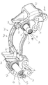
Figure 1 is an isometric view of a brake pad carrier according to the present invention, -
Figure 2 is an isometric view of a brake bridge according to the present invention, -
Figure 3 is an isometric view of an air operated brake actuator and housing according to the present invention, -
Figure 4 is an isometric view of an air operated brake assembly according to the present invention, -
Figure 5 is an isometric view of part of a hydraulically operated actuator according to the present invention, -
Figure 6 is a view similar tofigure 5 further including further components, -
Figure 7 is an isometric view of a hydraulically operated brake assembly according to the present invention, and -
Figure 8 is a cross section view offigure 4 . - With reference to
figures 1 to 8 there is shown an air operatedbrake assembly 10 in particular an air operated service brake assembly. The air operatedservice brake assembly 10 is solely air operated. The air operated service brake assembly is not hydraulically operated. With reference tofigures 1 to 8 there is also shown a hydraulically operated brake assembly 12, in particular a hydraulically operated service brake assembly. The hydraulically operated service brake assembly 12 is solely hydraulically operated. The hydraulically operated service brake assembly is not air operated. - The main components of the air operated brake assembly are an air operated
actuator 20, abrake carrier 30, abridge 40 andslide pins 61 and 62. The air operatedactuator 20 is solely air operated. The air operatedactuator 20 is not hydraulically operated. - The major components of the hydraulically operated brake assembly are a hydraulically operated actuator 50, a brake carrier 30', a bridge 40' and slide pins 61' and 62'.
Brake carrier 30 is the same as brake carrier 30',bridge 40 is the same as bridge 40', slide pin 61 is the same as slide pin 61' andslide pin 62 is the same as slide pin 62'. As suchfigures 1 and2 have been labelled accordingly. The hydraulically operated actuator 50 is solely hydraulically operated. The hydraulically operated actuator 50 is not air operated. -
Brake carrier 30 includesattachment holes 31,inboard pad abutments 32,arms 33 andoutboard pad abutments 34. Thebrake carrier 30 also includes slide pin holes (not shown, but which will be further described below). - The
bridge 40 includes abody 43, afirst arm 41 extends from a first end of the body and asecond arm 42 extends from a second end of the body. The first arm includes attachment holes 44 and thesecond arm 42 includesattachment holes 45. - The air operated actuator 20 (shown schematically in
figure 8 ) is housed withinhousing 23. The housing includesfirst attachment holes 21 andsecond attachment holes 22. The housing also includesslide pin holes 25. The housing includes arecess 26 in which is housed the air operatedactuator 20. The air operated actuator is a set of mechanical components well known in the art, for example seeUS6354407 . - However, in summary an air actuator chamber (not shown) is attached to
flange 28 of the housing and operates by selective introduction of pressurised air into/out of the chamber to cause a piston of the air operated actuator to selectively move in the direction of arrow A when it is required to apply the brake and in the direction of arrow B when it is required to release the brake. - The hydraulically operated actuator 50 includes a
body 53. The body hasfirst attachment holes 51 andsecond attachment holes 52. The body also includesslide pin holes 55. Thebody 53 includes arecess 56. The recess is at least defined by a first piston bore 56A and a second piston bore 56B. The first piston bore and second piston bore are both hydraulically linked tohydraulic port 58. Afirst piston 59A is slideably received in the first piston bore 56A and a second piston 59B is slideably received in the second piston bore 56B. - Assembly of the air operated
brake assembly 10 is as follows:-
The air operatedactuator 20 is assembled into therecess 26 and secured to thehousing 23 via any suitable method (not shown) e.g. bolts. - The
slide pins 61, 62 are positioned adjacent their respective slide pin holes andbolts 36 are threaded in to the slide pin holes to secure the pins to thecarrier 30. - The
housing 23 is attached to thebrake carrier 30 by inserting theslide pins 61 and 62 into theslide pin holes 25 ofhousing 23. The housing is therefore slideably received on theslide pin 61 and 62 which in turn are securely attached to thebrake carrier 30. - The
bridge 40 is then attached viabolts 63 passing through thefirst attachment holes 21 and being screwed into the threaded attachment holes 44 on thebridge 40. In asimilar manner bolts 64 are passed through thesecond attachment holes 22 of thehousing 23 and are threaded into threadedattachment holes 45 of thebridge 40. As will be appreciated, such an arrangement provides for an air operated brake assembly wherein the air operatedactuator 20 andbridge 40 are slideably attached to thebrake carrier 30. - Assembly of the hydraulically operated brake assembly is as follows.
- The
pistons 59A and 59B are assembled into the appropriate first and second piston bores 56A and 56B together with any necessary piston seals and dust seals. - The slide pins 61', 62' are attached at the slide pin holes of carrier 30' via bolts 36' in a manner as described above with respect to slide
pins 61, 62 andcarrier 30. - The
body 53 is attached to the brake carrier 30' by inserting the slide pins 61' and 62' into the slide pin holes 25' ofbody 53. Thebody 53 is therefore slideably received on the slide pins 61' and 62' which in turn are securely attached to the brake carrier 30'. - The bridge 40' is then attached via bolts 63' passing through the first attachment holes 51 and being screwed into the threaded attachment holes 44' on the bridge 40'. In a similar manner bolt 64' are passed through the second attachment holes 52 of the
housing 23 and are threaded into threaded attachment holes 45' of the bridge 40'. As will be appreciated, such an arrangement provides for a hydraulically operated brake assembly wherein the hydraulically operated actuator 50 and bridge 40' are slideably attached to the brake carrier 30'. - Operation of a hydraulically operated brake is well known in the art, but in summary in order to apply the brake pressurised hydraulic fluid is supplied to port 58 which causes the
pistons 59A and 59B to advance towards the brake disc thereby applying brake. When it is required to release the brake, hydraulic pressure is released atport 58 thereby allowing the seals and the like to retract thepistons 59A and 59B which in turn releases the brake. - As will be appreciated, the invention enables the manufacture of an air actuated brake (which is only air operated) and a hydraulically actuated brake (which is only hydraulically operated) using major components which are the same. This allows for economies of scale. Firstly in respect of the brake components themselves, and secondly in respect of the axles the brakes are fitted to.
- As described above, the brake carrier, bridge, and both slide pins are the same on the air operated
brake assembly 10, and the hydraulically operated brake assembly 12. A further component which may be the same arebolts 63 and 63',bolts 64 and 64',bolts 36 and 36', brake pad straps 70 and 70', the brake pads used with the air operatedbrake assembly 10 and the hydraulically operated brake assembly 12, and also the disc used with the air operatedbrake assembly 10 and the hydraulically operated brake assembly 12. As such, significant economies of scale can be used when manufacturing air operated brake assemblies and hydraulically operated brake assemblies according to the present invention. - As described above, the
brake carrier 30 is the same as the brake carrier 30'.Brake carrier 30 and 30' may be made from a casting. The casting used to makebrake carrier 30 and brake carrier 30' may be a common casting. Thus, under certain situations, for example different installations, it may be necessary to make thebrake carrier 30 of the air operated brake assembly slightly different from the brake carrier 30' of the hydraulically operated bake assembly. Thus, thebrake carrier 30, when made from a common casting, may require minor machining differences to a brake carrier 30' made from the common casting. As such, a further aspect of the present invention provides for economies of scale in respect of manufacturing a common casting that can be machined in a first manner to provide an air operated brake assembly and may be machined in a second manner to provide a hydraulically operated brake assembly. - Similarly, the
bridge 40 and 40' may be made from a casting. Under certain circumstances, for example for particular installations, it may be necessary to machine thebridge 40 in a slightly different manner to machining of the bridge 40'. Nevertheless, thebridge 40 and 40' may be made from a common casting with thebridge 40 being machined in the first manner to provide the air operated brake assembly and with the bridge 40' being operated in a second manner to provide the hydraulically operated brake assembly. - Air operated brake assemblies (which are only operated by air and not hydraulically operated) are typically used on heavy vehicles such as lorries, trucks, buses etc. Hydraulically operated brakes (which are only hydraulically operated and not air operated) are typically used on lighter vehicles such as passenger cars. This is because the ability to absorb heat energy of a hydraulically operated system is typically less than the ability to absorb heat on an air operated system. It is for this reason that air operated braking systems have been fitted to heavy vehicles such as lorries, trucks and buses etc since braking systems of such heavy vehicles need to dissipate significant amounts of heat.
- With the advent of regenerative braking systems (i.e. braking systems which convert the kinetic energy of the moving vehicle into a re-usable form of energy (such as electrical energy within a battery of the vehicle or kinetic energy within a flywheel of the vehicle), then because the brakes of such vehicles no longer are required to dissipate such large amounts of energy as heat, it becomes possible to use hydraulically operated brakes on vehicle which have traditionally used air operated brakes. The present invention allows brake manufacturers to supply both air operated brakes and hydraulically operated brakes to manufacturers of heavy vehicles in a cost efficient manner.
- When vehicles are serviced and it is necessary to repair a brake assembly, the person servicing the vehicle will often exchange the old (used) brake assembly for a previously repaired (refurbished) brake assembly. In this way the person repairing the vehicle is able to quickly repair the vehicle and hence return the vehicle to service quickly.
- Similarly, the person supplying a repaired (refurbished) brake assembly (the brake repairer) will receive the old (used) brake assembly in exchange. This can then be repaired and subsequently exchanged for another old (used) brake assembly when another vehicle requires a repaired (refurbished) brake assembly. As such a particular brake assembly may be removed from one vehicle, subsequently repaired, and then subsequently fitted to a second vehicle. With the advent of heavy vehicles using regenerative braking, then it can be expected that progressively more vehicles in the "vehicle park" (i.e. vehicles which are in use) might have hydraulically operated brakes, and progressively fewer vehicles might have air operated brake assemblies. As such, because the present invention uses components on an air operated brake assembly and on a hydraulically operated brake assembly that are common to both, then a brake repairer can easily rework one type of brake assembly e.g. an air operated brake assembly to provide a different type of brake assembly e.g. a hydraulically operated brake assembly which hydraulically operated brake assembly may be used with a heavy vehicle having a regenerative braking system.
- As shown in
figures 4 and8 the solely air operatedactuator 20 is housed withinhousing 23. As shown infigure 7 the solely hydraulically operated actuator 50 is used in place of the air operatedactuator 20 andhousing 23. In further embodiments thehousing 23 may include a hydraulically operated actuator instead of an air operated actuator. Such an arrangement would provide for further economies of scale since the hydraulically operated actuator contained withinhousing 23 would not require slide pin holes 55, the first attachment holes 51, or the second attachment holes 52, since these features would already be provided on thehousing 23 as the slide pin holes 25, first attachment holes 21 and second attachment holes 22 respectively. Thus, thehousing 23 may be suitable for receiving the air operatedbrake actuator 20 and may also be suitable for receiving a hydraulically operated brake actuator (not shown). If it is decided to make an air operated brake assembly then an air operated brake actuator will be assembled into thehousing 23, and if it is desired to make a hydraulically operated brake assembly, then a hydraulically operated brake actuator will be assembled into thehousing 23.
Claims (13)
- A method of making a brake assembly including the steps of:-a) providing a brake pad carrier,b) providing an air operated brake actuator suitable for attaching to the brake pad carrier,c) providing a hydraulically operated brake actuator suitable for attaching to the brake pad carrier,d) attaching only one of the air operated brake actuator and hydraulically operated brake actuator to the brake pad carrier to provide a brake assembly.
- The method as defined in claim 1 including the step of providing a bridge having a body for engaging a brake pad, a first arm extending from a first end of the body and a second arm extending from the second end of the body, wherein the air operated brake actuator is suitable for attaching to the bridge and the hydraulically operated brake actuator is suitable for attaching to the bridge,
wherein step d) includes attaching said one of the air operated brake actuator and hydraulically operated brake actuator to the bridge to provide the brake assembly. - A method as defined in claim 1 or 2 further including the step of providing an actuator housing suitable for receiving the air operated brake actuator, the actuator housing also being suitable for receiving the hydraulically operated brake actuator,
wherein step d) includes receiving said one of the air operated brake actuator and hydraulically operated brake actuator in the actuator housing and securing said one of the air operated brake actuator and hydraulically operated brake actuator to the actuator housing wherein said one of the air operated brake actuator and hydraulically operated brake actuator is attached to the brake pad carrier via the actuator housing. - A method as defined in claim 3 when dependent upon claim 2 wherein said one of the air operated brake actuator and hydraulically operated brake actuator is attached to the bridge via the actuator housing.
- A method of making a first brake assembly and second brake assembly including the steps of:-a) providing a first bare casting,b) providing a second bare casting the same as the first bare casting,c) machining the first bare casting in a first manner to provide a first brake pad carrier,d) attaching an air operated brake actuator to the first brake pad carrier to provide the first brake assemblye) machining the second bare casting in a second manner to provide a second brake pad carrier andf) attaching a hydraulically operated brake actuator to the second brake pad carrier to provide the second brake assembly.
- A method as defined in claim 5 further including the step of providing a first bridge having a body for engaging a brake pad, a first arm extending from a first end of the body and a second arm extending from a second end of the body,
providing a second bridge the same as the first brake bridge, attaching said first bridge to the air operated brake actuator to provide the first brake assembly and attaching the second bridge to the hydraulically operated brake actuator to provide the second assembly. - A method as defined in claim 5 or 6 further including providing a first actuator housing and providing a second actuator housing the same as the first actuator housing,
receiving the air operated brake actuator in the first actuator housing and securing the air operated brake actuator to the first actuator housing such that the air operated actuator is attached to the brake pad carrier via the first actuator housing to provide the first brake assembly,
receiving the hydraulically operated actuator in the second actuator housing and securing the hydraulically operated actuator to the second actuator housing wherein the hydraulically operated actuator is attached to the second brake pad carrier via the second actuator housing to provide the second brake assembly. - A method as defined in claim 7 when dependent upon claim 6 wherein the air operated brake actuator is attached to the first bridge via the first actuator housing and the hydraulically operated brake actuator is attached to the second bridge via the second actuator housing.
- A method of reworking an air operated brake actuator assembly, the air operated brake assembly including an air operated brake actuator attached to a brake pad carrier,
the re-working step including replacing the air operated brake actuator with a hydraulically operated brake actuator by removing the air operated brake actuator from the brake pad carrier and attaching a hydraulically operated brake actuator to the brake pad carrier. - A method as defined in claim 9 when the air operated brake assembly includes a bridge having a body for engaging a brake pad, a first arm extending from the first end of the body and the second arm extending from the second end of the brake body, the bridge being attached to the air operated brake actuator,
the re-working step including detaching the bridge from the air operated brake actuator and attaching the bridge to the hydraulically operated brake actuator. - A method as defined in claim 9 or 10 wherein the air operated brake assembly includes an actuator housing, the air operated brake actuator being received in the actuator housing,
the re-working step including removing the air operated brake actuator from the actuator housing, receiving the hydraulically operated brake actuator in the actuator housing, securing the hydraulically operated brake actuator to the actuator housing such that the hydraulically operated brake actuator is attached to the brake pad carrier via the actuator housing. - A method as defined in claim 12 when dependent upon claim 11 wherein the hydraulically operated brake actuator is attached to the bridge via the actuator housing.
- A lorry, truck, bus or other heavy vehicle having a regenerative braking system and including a hydraulically operated brake assembly manufactured by the method of any of any of claims 1 to 12.
Applications Claiming Priority (1)
| Application Number | Priority Date | Filing Date | Title |
|---|---|---|---|
| EP18164497.2A EP3546784A1 (en) | 2018-03-28 | 2018-03-28 | Brake assembly |
Publications (3)
| Publication Number | Publication Date |
|---|---|
| EP3546785A2 true EP3546785A2 (en) | 2019-10-02 |
| EP3546785A3 EP3546785A3 (en) | 2019-11-13 |
| EP3546785B1 EP3546785B1 (en) | 2023-08-09 |
Family
ID=61832361
Family Applications (2)
| Application Number | Title | Priority Date | Filing Date |
|---|---|---|---|
| EP18164497.2A Withdrawn EP3546784A1 (en) | 2018-03-28 | 2018-03-28 | Brake assembly |
| EP19162529.2A Active EP3546785B1 (en) | 2018-03-28 | 2019-03-13 | Brake assembly |
Family Applications Before (1)
| Application Number | Title | Priority Date | Filing Date |
|---|---|---|---|
| EP18164497.2A Withdrawn EP3546784A1 (en) | 2018-03-28 | 2018-03-28 | Brake assembly |
Country Status (3)
| Country | Link |
|---|---|
| US (1) | US11480225B2 (en) |
| EP (2) | EP3546784A1 (en) |
| CN (1) | CN110319130B (en) |
Families Citing this family (1)
| Publication number | Priority date | Publication date | Assignee | Title |
|---|---|---|---|---|
| CN113734114B (en) * | 2021-11-03 | 2022-09-02 | 杭州夏树科技有限公司 | Auxiliary emergency braking device for electric vehicle |
Citations (1)
| Publication number | Priority date | Publication date | Assignee | Title |
|---|---|---|---|---|
| US6354407B1 (en) | 1997-08-02 | 2002-03-12 | Meritor Automotive Inc. | Relating to disc brakes |
Family Cites Families (23)
| Publication number | Priority date | Publication date | Assignee | Title |
|---|---|---|---|---|
| US2888101A (en) * | 1956-04-02 | 1959-05-26 | Bendix Aviat Corp | Applying system for disk brake |
| GB818689A (en) * | 1956-04-02 | 1959-08-19 | Bendix Aviat Corp | Applying system for disk brake |
| DE1780438A1 (en) * | 1968-09-16 | 1972-02-10 | Westinghouse Bremsen Und Appba | Pressure medium two-circuit brake, especially for motor vehicles |
| US3312313A (en) * | 1965-06-23 | 1967-04-04 | Bendix Corp | Independently operable dual brake actuating apparatus |
| US4207968A (en) * | 1978-02-21 | 1980-06-17 | Caterpillar Tractor Co. | Double disc type brake system |
| SE510583C2 (en) * | 1994-10-24 | 1999-06-07 | Sab Wabco Ab | Safety brake arrangement in a brake actuator |
| US6196359B1 (en) * | 1998-04-10 | 2001-03-06 | Hayes Lemmerz International, Inc. | Vehicle braking system and braking method using a plurality of two-state actuators |
| DE60005921T2 (en) * | 2000-02-04 | 2004-05-19 | Vigel S.P.A., Borgaro Torinese | Device for processing brake calipers and carriers for motor vehicle disc brakes |
| US6305521B1 (en) * | 2000-04-24 | 2001-10-23 | General Motors Corporation | Hydraulically actuated piston with an air bleed |
| GB0618416D0 (en) * | 2006-09-19 | 2006-11-01 | Spa | A brake carrier |
| JP2009269465A (en) * | 2008-05-07 | 2009-11-19 | Toyota Motor Corp | Control device of braking device |
| US8380418B2 (en) * | 2009-08-26 | 2013-02-19 | GM Global Technology Operations LLC | Method for maintaining a brake rotor |
| GB201009030D0 (en) * | 2010-06-01 | 2010-07-14 | Meritor Heavy Vehicle Braking | Disc brake |
| IT1401115B1 (en) * | 2010-07-05 | 2013-07-12 | Freni Brembo Spa | BODY CALIPER OF A DISC BRAKE |
| WO2012041321A1 (en) * | 2010-09-29 | 2012-04-05 | Aalborg Universitet | Energy-recovering brake pad |
| ITPD20110154A1 (en) * | 2011-05-13 | 2012-11-14 | Freni Brembo Spa | FLOATING CALIPER FOR DISC BRAKE |
| US20120312642A1 (en) * | 2011-06-13 | 2012-12-13 | Bosco Jr Robert | Friction pad spreader, assembly including same and method of mounting thereof |
| EP2835553B1 (en) * | 2013-08-07 | 2018-04-25 | Meritor Heavy Vehicle Braking Systems (UK) Limited | Disc brake assembly |
| EP3051163B1 (en) * | 2015-01-28 | 2019-07-24 | Meritor Heavy Vehicle Braking Systems (UK) Limited | A disc brake |
| EP3121477B1 (en) * | 2015-07-21 | 2022-10-05 | Meritor Heavy Vehicle Braking Systems (UK) Limited | A disc brake assembly |
| CN105020301B (en) * | 2015-08-05 | 2017-11-10 | 万向钱潮(上海)汽车系统有限公司 | Floating type clipper disk brake |
| US9920800B2 (en) * | 2015-09-21 | 2018-03-20 | Arvinmeritor Technology, Llc | Brake assembly having a bridge |
| CN106402205B (en) * | 2016-10-28 | 2018-11-09 | 江苏理工学院 | Automobile electro-mechanical brake system wheel side self-powered brake actuator |
-
2018
- 2018-03-28 EP EP18164497.2A patent/EP3546784A1/en not_active Withdrawn
-
2019
- 2019-03-13 EP EP19162529.2A patent/EP3546785B1/en active Active
- 2019-03-26 US US16/365,049 patent/US11480225B2/en active Active
- 2019-03-27 CN CN201910235552.3A patent/CN110319130B/en active Active
Patent Citations (1)
| Publication number | Priority date | Publication date | Assignee | Title |
|---|---|---|---|---|
| US6354407B1 (en) | 1997-08-02 | 2002-03-12 | Meritor Automotive Inc. | Relating to disc brakes |
Also Published As
| Publication number | Publication date |
|---|---|
| EP3546784A1 (en) | 2019-10-02 |
| US11480225B2 (en) | 2022-10-25 |
| EP3546785B1 (en) | 2023-08-09 |
| US20190301549A1 (en) | 2019-10-03 |
| EP3546785A3 (en) | 2019-11-13 |
| CN110319130A (en) | 2019-10-11 |
| CN110319130B (en) | 2021-08-17 |
Similar Documents
| Publication | Publication Date | Title |
|---|---|---|
| CN1789750B (en) | Spring brake actuator with mid-located spring | |
| EP3546785B1 (en) | Brake assembly | |
| USRE32885E (en) | Air brake with collet locked push rod and air supply system | |
| CN102792046B (en) | Integral light spring braking execution device and axle assembly | |
| US10626939B2 (en) | Adhesive attachment of the disc brake pushrod plate to the diaphragm | |
| US4589704A (en) | Air brake with collet locked push rod and air supply system | |
| EP1892433A2 (en) | Disc brake actuator mounting arrangement | |
| EP3267066B1 (en) | Spring applied, hydraulically released wheel-mount brake having improved stationary disc support | |
| EP0062403B1 (en) | Disc brake caliper | |
| US6305509B1 (en) | Method and apparatus for enhancing vehicle braking efficiency | |
| Erjavec | Automotive brakes | |
| AU2015263336B2 (en) | Brake system | |
| DE4204139A1 (en) | Fully lined disc brake for lorries and vans - has friction heat from both brake parts dissipated by convection to outside via divided brake housing. | |
| Limberg et al. | Introduction to Foundation Brake Design | |
| EP1596091A1 (en) | A manual brake application assembly | |
| US12338864B1 (en) | Direct fit automotive brakes | |
| RU217947U1 (en) | Friction brake pad for vehicle brake pad repair kit | |
| EP2188162B1 (en) | Composite adapter plate | |
| EP3408150B1 (en) | An internal ventilated diaphragm-piston spring brake actuator | |
| Birge et al. | Disc Brakes Take on the Heavies | |
| Aubakirov | Uneven wear of Volvo caliper break pads | |
| DE19929059C1 (en) | Brake device for vehicles | |
| EP3251907A1 (en) | A spring brake actuator with a disc spring made of composite plastic | |
| CN114458707A (en) | Automobile disc brake caliper body and design method thereof | |
| Jones | Road-test. |
Legal Events
| Date | Code | Title | Description |
|---|---|---|---|
| PUAI | Public reference made under article 153(3) epc to a published international application that has entered the european phase |
Free format text: ORIGINAL CODE: 0009012 |
|
| STAA | Information on the status of an ep patent application or granted ep patent |
Free format text: STATUS: THE APPLICATION HAS BEEN PUBLISHED |
|
| AK | Designated contracting states |
Kind code of ref document: A2 Designated state(s): AL AT BE BG CH CY CZ DE DK EE ES FI FR GB GR HR HU IE IS IT LI LT LU LV MC MK MT NL NO PL PT RO RS SE SI SK SM TR |
|
| AX | Request for extension of the european patent |
Extension state: BA ME |
|
| PUAL | Search report despatched |
Free format text: ORIGINAL CODE: 0009013 |
|
| AK | Designated contracting states |
Kind code of ref document: A3 Designated state(s): AL AT BE BG CH CY CZ DE DK EE ES FI FR GB GR HR HU IE IS IT LI LT LU LV MC MK MT NL NO PL PT RO RS SE SI SK SM TR |
|
| AX | Request for extension of the european patent |
Extension state: BA ME |
|
| RIC1 | Information provided on ipc code assigned before grant |
Ipc: F16D 55/40 20060101AFI20191004BHEP |
|
| STAA | Information on the status of an ep patent application or granted ep patent |
Free format text: STATUS: REQUEST FOR EXAMINATION WAS MADE |
|
| 17P | Request for examination filed |
Effective date: 20200116 |
|
| RBV | Designated contracting states (corrected) |
Designated state(s): AL AT BE BG CH CY CZ DE DK EE ES FI FR GB GR HR HU IE IS IT LI LT LU LV MC MK MT NL NO PL PT RO RS SE SI SK SM TR |
|
| STAA | Information on the status of an ep patent application or granted ep patent |
Free format text: STATUS: EXAMINATION IS IN PROGRESS |
|
| 17Q | First examination report despatched |
Effective date: 20200702 |
|
| GRAP | Despatch of communication of intention to grant a patent |
Free format text: ORIGINAL CODE: EPIDOSNIGR1 |
|
| STAA | Information on the status of an ep patent application or granted ep patent |
Free format text: STATUS: GRANT OF PATENT IS INTENDED |
|
| INTG | Intention to grant announced |
Effective date: 20230315 |
|
| GRAS | Grant fee paid |
Free format text: ORIGINAL CODE: EPIDOSNIGR3 |
|
| GRAA | (expected) grant |
Free format text: ORIGINAL CODE: 0009210 |
|
| STAA | Information on the status of an ep patent application or granted ep patent |
Free format text: STATUS: THE PATENT HAS BEEN GRANTED |
|
| P01 | Opt-out of the competence of the unified patent court (upc) registered |
Effective date: 20230531 |
|
| AK | Designated contracting states |
Kind code of ref document: B1 Designated state(s): AL AT BE BG CH CY CZ DE DK EE ES FI FR GB GR HR HU IE IS IT LI LT LU LV MC MK MT NL NO PL PT RO RS SE SI SK SM TR |
|
| REG | Reference to a national code |
Ref country code: GB Ref legal event code: FG4D |
|
| REG | Reference to a national code |
Ref country code: CH Ref legal event code: EP |
|
| REG | Reference to a national code |
Ref country code: IE Ref legal event code: FG4D |
|
| REG | Reference to a national code |
Ref country code: DE Ref legal event code: R096 Ref document number: 602019034383 Country of ref document: DE |
|
| REG | Reference to a national code |
Ref country code: SE Ref legal event code: TRGR |
|
| REG | Reference to a national code |
Ref country code: LT Ref legal event code: MG9D |
|
| REG | Reference to a national code |
Ref country code: NL Ref legal event code: MP Effective date: 20230809 |
|
| REG | Reference to a national code |
Ref country code: AT Ref legal event code: MK05 Ref document number: 1597842 Country of ref document: AT Kind code of ref document: T Effective date: 20230809 |
|
| PG25 | Lapsed in a contracting state [announced via postgrant information from national office to epo] |
Ref country code: GR Free format text: LAPSE BECAUSE OF FAILURE TO SUBMIT A TRANSLATION OF THE DESCRIPTION OR TO PAY THE FEE WITHIN THE PRESCRIBED TIME-LIMIT Effective date: 20231110 |
|
| PG25 | Lapsed in a contracting state [announced via postgrant information from national office to epo] |
Ref country code: IS Free format text: LAPSE BECAUSE OF FAILURE TO SUBMIT A TRANSLATION OF THE DESCRIPTION OR TO PAY THE FEE WITHIN THE PRESCRIBED TIME-LIMIT Effective date: 20231209 |
|
| PG25 | Lapsed in a contracting state [announced via postgrant information from national office to epo] |
Ref country code: RS Free format text: LAPSE BECAUSE OF FAILURE TO SUBMIT A TRANSLATION OF THE DESCRIPTION OR TO PAY THE FEE WITHIN THE PRESCRIBED TIME-LIMIT Effective date: 20230809 Ref country code: PT Free format text: LAPSE BECAUSE OF FAILURE TO SUBMIT A TRANSLATION OF THE DESCRIPTION OR TO PAY THE FEE WITHIN THE PRESCRIBED TIME-LIMIT Effective date: 20231211 Ref country code: NO Free format text: LAPSE BECAUSE OF FAILURE TO SUBMIT A TRANSLATION OF THE DESCRIPTION OR TO PAY THE FEE WITHIN THE PRESCRIBED TIME-LIMIT Effective date: 20231109 Ref country code: NL Free format text: LAPSE BECAUSE OF FAILURE TO SUBMIT A TRANSLATION OF THE DESCRIPTION OR TO PAY THE FEE WITHIN THE PRESCRIBED TIME-LIMIT Effective date: 20230809 Ref country code: LV Free format text: LAPSE BECAUSE OF FAILURE TO SUBMIT A TRANSLATION OF THE DESCRIPTION OR TO PAY THE FEE WITHIN THE PRESCRIBED TIME-LIMIT Effective date: 20230809 Ref country code: LT Free format text: LAPSE BECAUSE OF FAILURE TO SUBMIT A TRANSLATION OF THE DESCRIPTION OR TO PAY THE FEE WITHIN THE PRESCRIBED TIME-LIMIT Effective date: 20230809 Ref country code: IS Free format text: LAPSE BECAUSE OF FAILURE TO SUBMIT A TRANSLATION OF THE DESCRIPTION OR TO PAY THE FEE WITHIN THE PRESCRIBED TIME-LIMIT Effective date: 20231209 Ref country code: HR Free format text: LAPSE BECAUSE OF FAILURE TO SUBMIT A TRANSLATION OF THE DESCRIPTION OR TO PAY THE FEE WITHIN THE PRESCRIBED TIME-LIMIT Effective date: 20230809 Ref country code: GR Free format text: LAPSE BECAUSE OF FAILURE TO SUBMIT A TRANSLATION OF THE DESCRIPTION OR TO PAY THE FEE WITHIN THE PRESCRIBED TIME-LIMIT Effective date: 20231110 Ref country code: FI Free format text: LAPSE BECAUSE OF FAILURE TO SUBMIT A TRANSLATION OF THE DESCRIPTION OR TO PAY THE FEE WITHIN THE PRESCRIBED TIME-LIMIT Effective date: 20230809 Ref country code: AT Free format text: LAPSE BECAUSE OF FAILURE TO SUBMIT A TRANSLATION OF THE DESCRIPTION OR TO PAY THE FEE WITHIN THE PRESCRIBED TIME-LIMIT Effective date: 20230809 |
|
| PG25 | Lapsed in a contracting state [announced via postgrant information from national office to epo] |
Ref country code: PL Free format text: LAPSE BECAUSE OF FAILURE TO SUBMIT A TRANSLATION OF THE DESCRIPTION OR TO PAY THE FEE WITHIN THE PRESCRIBED TIME-LIMIT Effective date: 20230809 |
|
| PG25 | Lapsed in a contracting state [announced via postgrant information from national office to epo] |
Ref country code: ES Free format text: LAPSE BECAUSE OF FAILURE TO SUBMIT A TRANSLATION OF THE DESCRIPTION OR TO PAY THE FEE WITHIN THE PRESCRIBED TIME-LIMIT Effective date: 20230809 |
|
| PG25 | Lapsed in a contracting state [announced via postgrant information from national office to epo] |
Ref country code: SM Free format text: LAPSE BECAUSE OF FAILURE TO SUBMIT A TRANSLATION OF THE DESCRIPTION OR TO PAY THE FEE WITHIN THE PRESCRIBED TIME-LIMIT Effective date: 20230809 Ref country code: RO Free format text: LAPSE BECAUSE OF FAILURE TO SUBMIT A TRANSLATION OF THE DESCRIPTION OR TO PAY THE FEE WITHIN THE PRESCRIBED TIME-LIMIT Effective date: 20230809 Ref country code: ES Free format text: LAPSE BECAUSE OF FAILURE TO SUBMIT A TRANSLATION OF THE DESCRIPTION OR TO PAY THE FEE WITHIN THE PRESCRIBED TIME-LIMIT Effective date: 20230809 Ref country code: EE Free format text: LAPSE BECAUSE OF FAILURE TO SUBMIT A TRANSLATION OF THE DESCRIPTION OR TO PAY THE FEE WITHIN THE PRESCRIBED TIME-LIMIT Effective date: 20230809 Ref country code: DK Free format text: LAPSE BECAUSE OF FAILURE TO SUBMIT A TRANSLATION OF THE DESCRIPTION OR TO PAY THE FEE WITHIN THE PRESCRIBED TIME-LIMIT Effective date: 20230809 Ref country code: CZ Free format text: LAPSE BECAUSE OF FAILURE TO SUBMIT A TRANSLATION OF THE DESCRIPTION OR TO PAY THE FEE WITHIN THE PRESCRIBED TIME-LIMIT Effective date: 20230809 Ref country code: SK Free format text: LAPSE BECAUSE OF FAILURE TO SUBMIT A TRANSLATION OF THE DESCRIPTION OR TO PAY THE FEE WITHIN THE PRESCRIBED TIME-LIMIT Effective date: 20230809 |
|
| REG | Reference to a national code |
Ref country code: DE Ref legal event code: R097 Ref document number: 602019034383 Country of ref document: DE |
|
| PG25 | Lapsed in a contracting state [announced via postgrant information from national office to epo] |
Ref country code: IT Free format text: LAPSE BECAUSE OF FAILURE TO SUBMIT A TRANSLATION OF THE DESCRIPTION OR TO PAY THE FEE WITHIN THE PRESCRIBED TIME-LIMIT Effective date: 20230809 |
|
| PLBE | No opposition filed within time limit |
Free format text: ORIGINAL CODE: 0009261 |
|
| STAA | Information on the status of an ep patent application or granted ep patent |
Free format text: STATUS: NO OPPOSITION FILED WITHIN TIME LIMIT |
|
| 26N | No opposition filed |
Effective date: 20240513 |
|
| PG25 | Lapsed in a contracting state [announced via postgrant information from national office to epo] |
Ref country code: SI Free format text: LAPSE BECAUSE OF FAILURE TO SUBMIT A TRANSLATION OF THE DESCRIPTION OR TO PAY THE FEE WITHIN THE PRESCRIBED TIME-LIMIT Effective date: 20230809 |
|
| REG | Reference to a national code |
Ref country code: CH Ref legal event code: PL |
|
| PG25 | Lapsed in a contracting state [announced via postgrant information from national office to epo] |
Ref country code: BG Free format text: LAPSE BECAUSE OF FAILURE TO SUBMIT A TRANSLATION OF THE DESCRIPTION OR TO PAY THE FEE WITHIN THE PRESCRIBED TIME-LIMIT Effective date: 20230809 |
|
| PG25 | Lapsed in a contracting state [announced via postgrant information from national office to epo] |
Ref country code: LU Free format text: LAPSE BECAUSE OF NON-PAYMENT OF DUE FEES Effective date: 20240313 |
|
| PG25 | Lapsed in a contracting state [announced via postgrant information from national office to epo] |
Ref country code: MC Free format text: LAPSE BECAUSE OF FAILURE TO SUBMIT A TRANSLATION OF THE DESCRIPTION OR TO PAY THE FEE WITHIN THE PRESCRIBED TIME-LIMIT Effective date: 20230809 |
|
| GBPC | Gb: european patent ceased through non-payment of renewal fee |
Effective date: 20240313 |
|
| PG25 | Lapsed in a contracting state [announced via postgrant information from national office to epo] |
Ref country code: MC Free format text: LAPSE BECAUSE OF FAILURE TO SUBMIT A TRANSLATION OF THE DESCRIPTION OR TO PAY THE FEE WITHIN THE PRESCRIBED TIME-LIMIT Effective date: 20230809 Ref country code: LU Free format text: LAPSE BECAUSE OF NON-PAYMENT OF DUE FEES Effective date: 20240313 Ref country code: BG Free format text: LAPSE BECAUSE OF FAILURE TO SUBMIT A TRANSLATION OF THE DESCRIPTION OR TO PAY THE FEE WITHIN THE PRESCRIBED TIME-LIMIT Effective date: 20230809 |
|
| REG | Reference to a national code |
Ref country code: BE Ref legal event code: MM Effective date: 20240331 |
|
| PG25 | Lapsed in a contracting state [announced via postgrant information from national office to epo] |
Ref country code: BE Free format text: LAPSE BECAUSE OF NON-PAYMENT OF DUE FEES Effective date: 20240331 |
|
| PG25 | Lapsed in a contracting state [announced via postgrant information from national office to epo] |
Ref country code: GB Free format text: LAPSE BECAUSE OF NON-PAYMENT OF DUE FEES Effective date: 20240313 |
|
| PG25 | Lapsed in a contracting state [announced via postgrant information from national office to epo] |
Ref country code: IE Free format text: LAPSE BECAUSE OF NON-PAYMENT OF DUE FEES Effective date: 20240313 |
|
| PG25 | Lapsed in a contracting state [announced via postgrant information from national office to epo] |
Ref country code: IE Free format text: LAPSE BECAUSE OF NON-PAYMENT OF DUE FEES Effective date: 20240313 Ref country code: GB Free format text: LAPSE BECAUSE OF NON-PAYMENT OF DUE FEES Effective date: 20240313 Ref country code: BE Free format text: LAPSE BECAUSE OF NON-PAYMENT OF DUE FEES Effective date: 20240331 Ref country code: CH Free format text: LAPSE BECAUSE OF NON-PAYMENT OF DUE FEES Effective date: 20240331 |
|
| PG25 | Lapsed in a contracting state [announced via postgrant information from national office to epo] |
Ref country code: CY Free format text: LAPSE BECAUSE OF FAILURE TO SUBMIT A TRANSLATION OF THE DESCRIPTION OR TO PAY THE FEE WITHIN THE PRESCRIBED TIME-LIMIT; INVALID AB INITIO Effective date: 20190313 |
|
| PG25 | Lapsed in a contracting state [announced via postgrant information from national office to epo] |
Ref country code: HU Free format text: LAPSE BECAUSE OF FAILURE TO SUBMIT A TRANSLATION OF THE DESCRIPTION OR TO PAY THE FEE WITHIN THE PRESCRIBED TIME-LIMIT; INVALID AB INITIO Effective date: 20190313 |
|
| PG25 | Lapsed in a contracting state [announced via postgrant information from national office to epo] |
Ref country code: TR Free format text: LAPSE BECAUSE OF FAILURE TO SUBMIT A TRANSLATION OF THE DESCRIPTION OR TO PAY THE FEE WITHIN THE PRESCRIBED TIME-LIMIT Effective date: 20230809 |
|
| PGFP | Annual fee paid to national office [announced via postgrant information from national office to epo] |
Ref country code: SE Payment date: 20260327 Year of fee payment: 8 |
|
| PGFP | Annual fee paid to national office [announced via postgrant information from national office to epo] |
Ref country code: DE Payment date: 20260327 Year of fee payment: 8 |
|
| PGFP | Annual fee paid to national office [announced via postgrant information from national office to epo] |
Ref country code: FR Payment date: 20260325 Year of fee payment: 8 |