EP3546745A1 - Packing stack carrier for paint and other fluid pumps - Google Patents
Packing stack carrier for paint and other fluid pumps Download PDFInfo
- Publication number
- EP3546745A1 EP3546745A1 EP19165912.7A EP19165912A EP3546745A1 EP 3546745 A1 EP3546745 A1 EP 3546745A1 EP 19165912 A EP19165912 A EP 19165912A EP 3546745 A1 EP3546745 A1 EP 3546745A1
- Authority
- EP
- European Patent Office
- Prior art keywords
- clip
- stack
- bracket
- packing
- piston
- Prior art date
- Legal status (The legal status is an assumption and is not a legal conclusion. Google has not performed a legal analysis and makes no representation as to the accuracy of the status listed.)
- Granted
Links
Images





Classifications
-
- F—MECHANICAL ENGINEERING; LIGHTING; HEATING; WEAPONS; BLASTING
- F16—ENGINEERING ELEMENTS AND UNITS; GENERAL MEASURES FOR PRODUCING AND MAINTAINING EFFECTIVE FUNCTIONING OF MACHINES OR INSTALLATIONS; THERMAL INSULATION IN GENERAL
- F16B—DEVICES FOR FASTENING OR SECURING CONSTRUCTIONAL ELEMENTS OR MACHINE PARTS TOGETHER, e.g. NAILS, BOLTS, CIRCLIPS, CLAMPS, CLIPS OR WEDGES; JOINTS OR JOINTING
- F16B2/00—Friction-grip releasable fastenings
- F16B2/20—Clips, i.e. with gripping action effected solely by the inherent resistance to deformation of the material of the fastening
- F16B2/22—Clips, i.e. with gripping action effected solely by the inherent resistance to deformation of the material of the fastening of resilient material, e.g. rubbery material
-
- F—MECHANICAL ENGINEERING; LIGHTING; HEATING; WEAPONS; BLASTING
- F04—POSITIVE - DISPLACEMENT MACHINES FOR LIQUIDS; PUMPS FOR LIQUIDS OR ELASTIC FLUIDS
- F04B—POSITIVE-DISPLACEMENT MACHINES FOR LIQUIDS; PUMPS
- F04B53/00—Component parts, details or accessories not provided for in, or of interest apart from, groups F04B1/00 - F04B23/00 or F04B39/00 - F04B47/00
- F04B53/16—Casings; Cylinders; Cylinder liners or heads; Fluid connections
- F04B53/162—Adaptations of cylinders
- F04B53/164—Stoffing boxes
-
- F—MECHANICAL ENGINEERING; LIGHTING; HEATING; WEAPONS; BLASTING
- F16—ENGINEERING ELEMENTS AND UNITS; GENERAL MEASURES FOR PRODUCING AND MAINTAINING EFFECTIVE FUNCTIONING OF MACHINES OR INSTALLATIONS; THERMAL INSULATION IN GENERAL
- F16J—PISTONS; CYLINDERS; SEALINGS
- F16J15/00—Sealings
- F16J15/16—Sealings between relatively-moving surfaces
- F16J15/32—Sealings between relatively-moving surfaces with elastic sealings, e.g. O-rings
- F16J15/3248—Sealings between relatively-moving surfaces with elastic sealings, e.g. O-rings provided with casings or supports
- F16J15/3252—Sealings between relatively-moving surfaces with elastic sealings, e.g. O-rings provided with casings or supports with rigid casings or supports
-
- B—PERFORMING OPERATIONS; TRANSPORTING
- B05—SPRAYING OR ATOMISING IN GENERAL; APPLYING FLUENT MATERIALS TO SURFACES, IN GENERAL
- B05B—SPRAYING APPARATUS; ATOMISING APPARATUS; NOZZLES
- B05B9/00—Spraying apparatus for discharge of liquids or other fluent material, without essentially mixing with gas or vapour
- B05B9/007—At least a part of the apparatus, e.g. a container, being provided with means, e.g. wheels, for allowing its displacement relative to the ground
-
- F—MECHANICAL ENGINEERING; LIGHTING; HEATING; WEAPONS; BLASTING
- F04—POSITIVE - DISPLACEMENT MACHINES FOR LIQUIDS; PUMPS FOR LIQUIDS OR ELASTIC FLUIDS
- F04B—POSITIVE-DISPLACEMENT MACHINES FOR LIQUIDS; PUMPS
- F04B1/00—Multi-cylinder machines or pumps characterised by number or arrangement of cylinders
- F04B1/04—Multi-cylinder machines or pumps characterised by number or arrangement of cylinders having cylinders in star- or fan-arrangement
- F04B1/0404—Details or component parts
- F04B1/0408—Pistons
-
- F—MECHANICAL ENGINEERING; LIGHTING; HEATING; WEAPONS; BLASTING
- F04—POSITIVE - DISPLACEMENT MACHINES FOR LIQUIDS; PUMPS FOR LIQUIDS OR ELASTIC FLUIDS
- F04B—POSITIVE-DISPLACEMENT MACHINES FOR LIQUIDS; PUMPS
- F04B15/00—Pumps adapted to handle specific fluids, e.g. by selection of specific materials for pumps or pump parts
- F04B15/02—Pumps adapted to handle specific fluids, e.g. by selection of specific materials for pumps or pump parts the fluids being viscous or non-homogeneous
-
- F—MECHANICAL ENGINEERING; LIGHTING; HEATING; WEAPONS; BLASTING
- F04—POSITIVE - DISPLACEMENT MACHINES FOR LIQUIDS; PUMPS FOR LIQUIDS OR ELASTIC FLUIDS
- F04B—POSITIVE-DISPLACEMENT MACHINES FOR LIQUIDS; PUMPS
- F04B15/00—Pumps adapted to handle specific fluids, e.g. by selection of specific materials for pumps or pump parts
- F04B15/04—Pumps adapted to handle specific fluids, e.g. by selection of specific materials for pumps or pump parts the fluids being hot or corrosive
-
- F—MECHANICAL ENGINEERING; LIGHTING; HEATING; WEAPONS; BLASTING
- F04—POSITIVE - DISPLACEMENT MACHINES FOR LIQUIDS; PUMPS FOR LIQUIDS OR ELASTIC FLUIDS
- F04B—POSITIVE-DISPLACEMENT MACHINES FOR LIQUIDS; PUMPS
- F04B53/00—Component parts, details or accessories not provided for in, or of interest apart from, groups F04B1/00 - F04B23/00 or F04B39/00 - F04B47/00
-
- F—MECHANICAL ENGINEERING; LIGHTING; HEATING; WEAPONS; BLASTING
- F04—POSITIVE - DISPLACEMENT MACHINES FOR LIQUIDS; PUMPS FOR LIQUIDS OR ELASTIC FLUIDS
- F04B—POSITIVE-DISPLACEMENT MACHINES FOR LIQUIDS; PUMPS
- F04B53/00—Component parts, details or accessories not provided for in, or of interest apart from, groups F04B1/00 - F04B23/00 or F04B39/00 - F04B47/00
- F04B53/14—Pistons, piston-rods or piston-rod connections
- F04B53/143—Sealing provided on the piston
-
- F—MECHANICAL ENGINEERING; LIGHTING; HEATING; WEAPONS; BLASTING
- F04—POSITIVE - DISPLACEMENT MACHINES FOR LIQUIDS; PUMPS FOR LIQUIDS OR ELASTIC FLUIDS
- F04B—POSITIVE-DISPLACEMENT MACHINES FOR LIQUIDS; PUMPS
- F04B53/00—Component parts, details or accessories not provided for in, or of interest apart from, groups F04B1/00 - F04B23/00 or F04B39/00 - F04B47/00
- F04B53/14—Pistons, piston-rods or piston-rod connections
- F04B53/144—Adaptation of piston-rods
-
- F—MECHANICAL ENGINEERING; LIGHTING; HEATING; WEAPONS; BLASTING
- F04—POSITIVE - DISPLACEMENT MACHINES FOR LIQUIDS; PUMPS FOR LIQUIDS OR ELASTIC FLUIDS
- F04B—POSITIVE-DISPLACEMENT MACHINES FOR LIQUIDS; PUMPS
- F04B53/00—Component parts, details or accessories not provided for in, or of interest apart from, groups F04B1/00 - F04B23/00 or F04B39/00 - F04B47/00
- F04B53/14—Pistons, piston-rods or piston-rod connections
- F04B53/144—Adaptation of piston-rods
- F04B53/147—Mounting or detaching of piston rod
-
- F—MECHANICAL ENGINEERING; LIGHTING; HEATING; WEAPONS; BLASTING
- F04—POSITIVE - DISPLACEMENT MACHINES FOR LIQUIDS; PUMPS FOR LIQUIDS OR ELASTIC FLUIDS
- F04B—POSITIVE-DISPLACEMENT MACHINES FOR LIQUIDS; PUMPS
- F04B19/00—Machines or pumps having pertinent characteristics not provided for in, or of interest apart from, groups F04B1/00 - F04B17/00
- F04B19/20—Other positive-displacement pumps
- F04B19/22—Other positive-displacement pumps of reciprocating-piston type
Definitions
- the present disclosure relates to piston pumps, and in particular sealing elements within the pumps.
- Piston pumps are used to pump fluids, typically at high pressures.
- the pump elements disclosed herein are particularly well suited for pumping paint, finishes, and other coatings which are typically abrasive, viscous, and/or otherwise difficult to pump. Packings are used to facilitate forming a dynamic seal in such difficult to handle fluid applications.
- Packings are rings of sealing material.
- a packing can be formed from leather, rubber, polymer (e.g., ultra high molecular weight polyethylene or UHMWPE), and/or synthetic material.
- Packings commonly have complementary cross sections, such as having U or V cross section shapes, to mate and stack upon one another. Packings are typically arranged in a stack, such as six or more packing rings mounted atop one another. Packings of different types can be arranged in an alternating arrangement, such as leather-synthetic-leather-synthetic-leather-synthetic or other combination.
- Glands are rings (typically metal) which having complementally cross sectional profiles, such as having U or V projecting and recessed cross sectional shapes to mate and stack with the packings.
- a set of two glands are typically placed at both ends (top and bottom) of the stack of packings, bracketing the stack of packings. The glands can then be fixed to a component of the pump. The glands can retain the stack of packings within the pump.
- Packings are used as dynamic sealing surfaces in which the packings either move with the piston or the piston moves relative to the packings.
- a stack of packings can be mounted on a piston rod such that the packings move with the piston rod and slide along the inner surface of the bore of the cylinder.
- a stack of packings can be mounted on the inside bore of a cylinder and are held static relative to the cylinder while the piston slides along the packings.
- the packings seal between the cylinder and the piston to prevent leakage of fluid past the packings between the cylinder and the piston.
- a first set of packings seal along the pump rod of the piston, commonly known as throat packings.
- a second set of packings seal along the piston head of the piston, commonly known as piston packings.
- Packings can be difficult to handle and install, particularly when in a stacked arrangement.
- the packings are arranged coaxial and contacting one another, but can fall out of coaxial, contacting alignment when not secured in place. If one packing in a stack is not coaxially aligned with the rest of the packings in a stack, then the stack cannot be properly aligned within the cylinder and/or on the piston.
- a clip for holding a stack of packing rings having a first stack end, a second stack end, and a central bore through both the first stack end and the second stack end, on a longitudinal axis.
- the clip includes a spine having a first end and a second end; a first bracket extending from the first end of the spine partially around the axis, the first bracket configured to hold the first stack end; and a second bracket extending from the second end of the spine partially around the axis, the second bracket configured to hold the second stack end.
- the first bracket and the second bracket define a side opening oriented to allow the packing stack to slide laterally relative to the axis and out from between the first bracket and the second bracket.
- a method includes sliding a packing assembly in a first axial direction and onto an end of a piston for a reciprocating fluid pump.
- the packing assembly includes a clip having at least one bracket defining a side opening; and a packing stack retained on the clip and held in axial alignment on a longitudinal axis by the at least one bracket of the clip.
- the method further includes shifting the clip laterally relative to the piston to disengage the packing stack from the clip through the side opening leaving the packing stack disposed on the piston.
- an assembly includes a packing stack formed from a plurality of packing rings dispose on a stack axis, and a clip configured to hold the packing stack.
- the packing stack includes a first stack end; a second stack end disposed opposite the first stack end; and a central bore extending through the plurality of packing rings between the first stack end and the second stack end.
- the clip includes a spine having a first end and a second end; a top portion extending partially around the axis from the first end of the spine; and a bottom portion extending partially around the axis from the second end of the spine.
- the top portion and the bottom portion define an axially extending side opening oriented to allow the packing stack to slide laterally relative to the axis into and out of an area defined between the top portion, the bottom portion, and the spine.
- a clip for holding a stack of packing rings having a first stack end, a second stack end, and a central bore through both the first stack end and the second stack end, on a longitudinal axis comprising: a spine having a first end and a second end; a first bracket extending from the first end of the spine partially around the axis, the first bracket configured to hold the first stack end; and a second bracket extending from the second end of the spine partially around the axis, the second bracket configured to hold the second stack end; wherein the first bracket and the second bracket define a side opening oriented to allow the packing stack to slide laterally relative to the axis and out from between the first bracket and the second bracket.
- the first bracket comprises a plurality of upper arms extending from opposite lateral sides of the spine, such that the plurality of upper arms at least partially define the side opening.
- the plurality of upper arms include a first upper arm extending from a first lateral side of the spine and a second upper arm extending from a second lateral side of the spine, wherein the first upper arm and the second upper arm are configured to elastically deform to increase and decrease a width of the side opening, to thereby permit the stack of packing rings to slide laterally through the side opening.
- the second bracket comprises a plurality of lower arms extending from opposite lateral sides of the spine, such that the plurality of lower arms at least partially define the side opening.
- the plurality of lower arms include a first lower arm extending from a first lateral side of the spine and a second lower arm extending from a second lateral side of the spine, wherein the first lower arm and the second lower arm are configured to elastically deform to increase and decrease a width of the side opening, to thereby permit the stack of packing rings to slide laterally through the side opening.
- the side opening is disposed opposite the spine.
- the spine is the only portion of the clip that connects the first bracket and the second bracket.
- the first bracket defines a first end opening extending axially through the first bracket, such that the central opening of the stack of packing rings is exposed through the first end opening.
- the second bracket defines a second end opening extending axially through the second bracket, such that the central opening of the stack of packing rings is exposed through the second end opening.
- the first bracket further comprises at least one block projecting radially inward from the first bracket and into the first axial opening, the at least one block configured to extend over and cover at least part of the central bore of the stack of packing rings; and the second bracket does not include a projection extending over and covering at least part of the central bore, such the central bore is fully exposed through the second end opening.
- the first bracket comprises: a plurality of arcuate upper arms extending from opposite lateral sides of the spine, such that distal ends of the plurality of arcuate upper arms at least partially define the side opening;
- the second bracket comprises: a plurality of arcuate lower arms extending from opposite lateral sides of the spine, such that distal ends of the plurality of arcuate lower arms at least partially define the side opening; and a first lower tab projecting radially from a first one of the plurality of arcuate lower arms, the first lower tab configured to engage the second stack end of the stack of packing rings to axially retain the stack of packing rings within the clip; the block extends from a first one of the plurality of arcuate upper arms.
- the clip further comprises: a first guide plate disposed at a distal end of the first one of the plurality of arcuate upper arms, the first guide plate extending over the side opening; a first flat disposed below the first guide plate at the distal end of the first one of the plurality of arcuate upper arms; a second guide plate disposed at a distal end of a second one of the plurality of arcuate upper arms, the second guide plate extending over the side opening; and a second flat disposed below the second guide plate at the distal end of the second one of the plurality of arcuate upper arms; wherein the first flat is disposed across from and oriented towards the second flat such that the side opening is at least partially defined between the first flat and the second flat.
- an assembly comprising: a clip as set out above; and the packing stack mounted within the clip and retained within the clip by the first bracket and the second bracket.
- a method of loading a piston with the assembly set out above comprising: axially aligning the stack of packing rings with an end of the piston; shifting the clip axially over the end of the piston such that the piston extends into the central bore of the stack of packing rings; and pulling the clip laterally relative to the piston and the stack of packing rings such that the stack of packing rings are released from the clip through the side opening of the clip while the stack of packing rings remain on the end of the piston.
- the method comprises pulling the clip laterally relative to the piston comprises pulling the clip in a direction orthogonal to the axis.
- the first bracket comprises a plurality of upper arms extending from opposite lateral sides of the spine, such that the plurality of upper arms at least partially define the side opening;
- the second bracket comprises a plurality of lower arms extending from opposite lateral sides of the spine, such that the plurality of lower arms at least partially define the side opening; and the plurality of upper arms and the plurality of lower arms flex to widen the side opening as the clip is pulled laterally relative to the piston.
- the method comprises forming the stack of packing rings by: arranging a plurality of packings in a desired configuration; placing a first gland at a first end of the packings; and placing a second gland at a second end of the packings; aligning the packing stack with the side opening; and shifting the packing stack laterally through the side opening and into the clip.
- the method comprises blocking a first end opening defined through the first bracket with at least one tab extending laterally towards the axis from the first bracket to prevent an object having a diameter approximately equal to a dimeter of the first end opening from passing through the first end opening.
- a method comprising: sliding a packing assembly in a first axial direction and onto an end of a piston for a reciprocating fluid pump, wherein the packing assembly comprises: a clip having at least one bracket defining a side opening; and a packing stack retained on the clip and held in axial alignment on a longitudinal axis by the at least one bracket of the clip; and shifting the clip laterally relative to the piston to disengage the packing stack from the clip through the side opening leaving the packing stack disposed on the piston.
- an assembly comprising: a packing stack formed from a plurality of packing rings dispose on a stack axis, the packing stack comprising: a first stack end; a second stack end disposed opposite the first stack end; and a central bore extending through the plurality of packing rings between the first stack end and the second stack end; and a clip configured to hold the packing stack, the clip comprising: a spine having a first end and a second end; a top portion extending partially around the axis from the first end of the spine; and a bottom portion extending partially around the axis from the second end of the spine; wherein the top portion and the bottom portion define an axially extending side opening oriented to allow the packing stack to slide laterally relative to the axis into and out of an area defined between the top portion, the bottom portion, and the spine.
- FIG. 1 is a cross-sectional view of pump 10.
- Pump 10 includes piston 12, cylinder 14, check valves 16a, 16b, retaining nut 18, packing stack 20a, and packing stack 20b.
- Piston 12 includes piston rod 22 and piston head 24.
- Piston rod 22 includes first end 26 and second end 28.
- First end 26 includes rod head 30.
- Intake housing 32 is disposed at a bottom of cylinder 14.
- Packing stack 20a includes glands 34a, 34b and packings 36a, 36b.
- Packing stack 20b also includes glands 34a, 34b and packings 36a, 36b.
- Pump 10 reciprocates piston 12 within cylinder 14 to pump various fluids, examples of which include paint, water, oil, stains, finishes, aggregate, coatings, and solvents, amongst other options.
- Pump 10 can generate high fluid pumping pressures, such as 3,000-5,000 pounds per square inch (psi) or even higher. High fluid pumping pressure is useful for atomizing the fluid into a spray for applying the fluid to a surface.
- Piston 12 is disposed within cylinder 14 and configured to reciprocate within cylinder 14.
- First end 26 extends out of cylinder 14 through throat packings 20b.
- Rod head 30 is disposed outside of cylinder 14 and is configured to connect to a drive system that drives reciprocation of piston 12.
- Piston head 24 is connected to second end 28 of piston rod 22.
- Piston head 24 can be connected to piston rod 22 in any desired manner, such as by interfaced threading or welding.
- piston head 24 is integrally formed with piston rod 22, such that piston rod 22 and piston head 24 form a unitary assembly.
- Check valve 16b is disposed within piston rod 22. In the example shown, piston head 24 retains check valve 16b within piston rod 22.
- Intake housing 32 is connected to the bottom of cylinder 14. In some examples, intake housing 32 is threadedly connected to cylinder 14.
- Check valve 16a is disposed within intake housing 32 and forms a one-way check valve to allow fluid to flow downstream into intake housing 32 while preventing the fluid from flowing upstream out of intake housing 32.
- Retaining nut 18 is located at an opposite end of pump 10 from intake housing 32. Retaining nut 18 is secured to cylinder 14 and is configured to retain packing stack 20b within cylinder 14. Retaining nut 18 can be secured to cylinder 14 in any desired manner, such as by interfaced threading. Packing stack 20b is disposed within cylinder 14. Piston rod 22 extends through packing stack 20b and can reciprocate relative to packing stack 20b.
- Packing stack 20b is configured to seal between piston rod 22 and the inner wall of cylinder 14.
- Packing stack 20a is disposed within cylinder 14 between piston 12 and cylinder 14.
- Packing stack 20a is configured to seal between piston 12 and the inner wall of cylinder 14.
- Piston 12 reciprocates within cylinder 14 to increase and decrease the volumes of both upstream chamber 15 and downstream chamber 17. Increasing and decreasing the volumes of upstream chamber 15 and downstream chamber 17 draws fluid into cylinder 14 and pumps the fluid downstream out of cylinder 14.
- upstream chamber 15 expands creating suction and causing check valve 16a to open, while downstream chamber 17 shrinks, thereby causing check valve 16b to close and driving the fluid out of downstream chamber 17.
- upstream chamber 15 shrinks, thereby causing check valve 16a to close, while downstream chamber 17 expands, opening check valve 16b and causing the fluid to flow from upstream chamber 15 to downstream chamber 17 through check valve 16b and piston rod 22.
- the fluid enters downstream chamber 17 through outlet 19 formed though piston rod 22.
- Pump 10 can be a double displacement pump such that piston 12 drives fluid downstream out of cylinder 14 during both the upstroke and the downstroke.
- packings 36a, 36b are arrayed between glands 34a, 34b.
- Packings 36a, 36b and glands 34a, 34b can be of any desired size and in any desired arrangement for suitably sealing around piston 12 during reciprocation of piston 12.
- Packings 36a, 36b are rings of sealing material and can be formed from leather, rubber, polymer (e.g., ultra high molecular weight polyethylene or UHMWPE), and/or synthetic material.
- Packings 36a, 36b commonly have complementary cross sections, such as having U or V cross section shapes, to mate and stack upon one another. Packings 36a, 36b are typically arranged in a stack, such as six or more packing rings mounted atop one another.
- Packings 36a, 36b of different types can be arranged in an alternating arrangement, such as leather-synthetic-leather-synthetic-leather-synthetic or other combinations.
- Glands 34a, 34b are typically formed from a metal.
- Each of packing stack 20b and packing stack 20a typically include one male gland, such as gland 34a, and one female gland, such as gland 34b, to complement the cross-sections of packings 36a, 36b. Packings 36a, 36b are sandwiched between glands 34a, 34b.
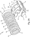
- FIG. 2A is an exploded view of assembly 38.
- FIG. 2B is a partially exploded view of assembly 38.
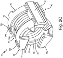
- FIG. 2C is an isometric view of assembly 38.
- Assembly 38 includes packing stack 20 and clip 40.
- Packing stack 20 includes glands 34a, 34b; packings 36a, 36b; first stack end 42; second stack end 44; and central bore 46.
- Clip 40 includes top side 41, bottom side 43, top portion 48, bottom portion 50, spine 52, and side opening 54.
- Top portion 48 includes upper arms 56a, 56b.
- Bottom portion 50 includes lower arms 58a, 58b.
- Packings 36a, 36b are arrayed in a coaxial stack about longitudinal axis A-A prior to installation. Glands 34a, 34b are disposed on opposite sides of packings 36a, 36b.
- Top portion 48 extends around top side 41 of clip 40. Top portion 48 can also be referred to as a bracket. Bottom portion 50 extends around bottom side 43 of clip 40. Bottom portion 50 can also be referred to as a bracket. As shown, top portion 48 extends from a first axial end of spine 52 and bottom portion 50 extends form a second axial end of spine 52. In some examples, spine 52 is the only portion of clip 40 that extends between and connects top portion 48 and bottom portion 50.
- top portion 48 and bottom portion 50 can be arcuate, though it is understood that each of top portion 48 and bottom portion 50 can be of any desired configuration for receiving and retaining packing stack 20.
- Upper arms 56a, 56b extend from opposite lateral sides of spine 52.
- Lower arms 58a, 58b similarly extend from opposite lateral sides of spine 52.
- Side opening 54 is defined between upper arm 56a and upper arm 56b, and between lower arm 58a and lower arm 58b.
- packings 36a, 36b and glands 34a, 34b are shown in an exploded configuration, such that packings 36a, 36b are not in contact in a coaxially aligned stack.
- packings 36a, 36b and glands 34a, 34b Prior to installation on clip 40, packings 36a, 36b and glands 34a, 34b are placed in the arrangement shown in FIG. 2B , such that packings 36a, 36b and glands 34a, 34b are in contact and in coaxial alignment for installation on piston 12 ( FIGS. 1 and 3A-3C ).
- the assembled packing stack 20 formed by packings 36a, 36b and glands 34a, 34b is installed on clip 40 to form the arrangement shown in FIG. 2C .
- Packing stack 20 is shifted laterally into clip 40 through side opening 54.
- Upper arms 56a, 56b and lower arms 58a, 58b are configured to elastically expand as packing stack 20 passes onto clip 40 through side opening 54.
- Upper arms 56a, 56b and lower arms 58a, 58b are further configured to elastically contract to retain packing stack 20 on clip 40 once inserted.
- Upper arms 56a, 56b and lower arms 58a, 58b thereby retain packing stack 20 on clip 40 in the desired contacting and coaxial arrangement.
- Spine 52 can also flex in response to packing stack 20 passing through side opening 54 and into clip 40.
- Upper arms 56a, 56b engage first stack end 42 to prevent packing stack 20 from shifting laterally. As discussed in more detail below, upper arms 56a, 56b can further prevent axial movement of packing stack 20 relative to clip 40. Lower arms 58a, 58b engage second stack end 44 to prevent packing stack 20 from shifting laterally. As discussed in more detail below, lower arms 58a, 58b can further prevent axial movement of packing stack 20 relative to clip 40. Clip 40 prevents packings 36a, 36b and glands 34a, 34b from separating prior to and during installation, thereby maintaining packings 36a, 36b and glands 34a, 34b in the desired co-axial stack for proper alignment during placement on piston 12.
- Central bore 46 is exposed on both the top and bottom sides of clip 40 to allow for insertion of piston 12 into packing stack 20 through central bore 46 of packing stack 20.
- a first end opening extends axially through top portion 48 such that central bore 46 is exposed through the first end opening
- a second end opening extends axially through bottom portion 50 such that central bore 46 is exposed through the second end opening.
- FIG. 3A is a first isometric view of piston 12 and assembly 38.
- FIG. 3B is a second isometric view of piston rod 22 and assembly 38.
- FIG. 3C is a third isometric view of piston 12 and assembly 38.
- Piston rod 22 of piston 12 is shown.
- Piston rod 22 includes first end 26 and second end 28.
- Second end 28 includes shoulder 60.
- Assembly 38 includes packing stack 20 and clip 40.
- FIGS. 3A-3C illustrate the installation of packing stack 20 on piston 12
- Assembly 38 is aligned with piston rod 22 such that second end 28 of piston rod 22 is coaxially aligned with central bore 46 through packing stack 20.
- assembly 38 is moved in direction A (e.g., axially) from the position shown in FIG. 3A to the position shown in FIG. 3B such that second end 28 is received within central bore 46.
- Gland 34a can contact shoulder 60 with packing stack 20 fully inserted onto piston rod 22. Shoulder 60 can thereby provide a visual indication to the user that packing stack 20 is properly positioned, and can provide a physical stop ensuring that packing stack 20 is properly positioned.
- piston head 24 ( FIG. 1 ) can then be attached (e.g., by threading) to piston rod 22 to capture packing stack 20 on piston rod 22.
- clip 40 is configured such that a piston head 24 can be inserted between upper arms 56a, 56b and into central bore 46 and then into the bore in second end 28 of piston rod 22 with clip 40 still disposed on packing stack 20.
- piston head 24 can connect to piston rod 22 with assembly 38 mounted on piston rod 22, such that piston head 24 retains packing stack 20 on piston rod 22 during removal of clip 40.
- clip 40 With packing stack 20 positioned on piston rod 22, clip 40 can be pulled laterally relative to piston rod 22 to remove clip 40 from packing stack 20, while leaving packing stack 20 on piston rod 22.
- Clip 40 can be pulled off of packing stack 20 in direction B (e.g., sideways) such that packing stack 20 is pulled through side opening 54.
- direction B is orthogonal to lateral axis A-A. In this way, clip 40 is not slid off of packing stack 20 in an axial direction along lateral axis A-A (i.e. parallel with lateral axis A-A).
- top portion 48 and bottom portion 50 and specifically upper arms 56a, 56b and lower arms 58a, 58b, to elastically flex as upper arms 56a, 56b and lower arms 58a, 58b first slide around and off of packing stack 20 and then completely disengage from packing stack 20.
- Clip 40 thereby leaves packings 36a, 36b and glands 34a, 34b coaxially aligned and mounted on piston rod 22 (with or without piston head 24 attached to piston rod 22).
- clip 40 can be moved axially (e.g., up and down parallel with axis A-A of piston 12) to place packing stack 20 on piston 12, and then moved sideways (e.g., laterally, orthogonal to the axial direction) to remove clip 40 from over packing stack 20 while leaving packing stack 20 mounted on piston 12.
- Clip 40 can be formed from plastic (e.g., UHMWPE, polyethylene) or metal (e.g., aluminum). Packing stack 20 can be snapped into place in clip 40 and can be unsnapped upon removal of clip 40 from packing stack 20. Elastic strain within the body of clip 40, such as between upper arms 56a, 56b and lower arms 58a, 58b, can pinch and hold the elements of packing stack 20 in place and in coaxial alignment within clip 40.
- plastic e.g., UHMWPE, polyethylene
- metal e.g., aluminum
- Assembly 38 provides significant advantages.
- One benefit of clip 40 is that packings 36a, 36b and glands 34a, 34b can be placed and held in packing stack 20 in a proper order prior to installation.
- packing stack 20 can be packaged in clip 40 (e.g., in a box, sack, blister pack, clamshell, or other package) with packings 36a, 36b and glands 34a, 34b in the correct order at the factory.
- packing stack 20 can be pre-oiled prior to assembly on clip 40 and packaging for shipment. The user, upon opening the package, does not need to order and assemble packings 36a, 36b and glands 34a, 34b. Also, the user does not need to individually place the elements of packing stack 20 on the piston 12.
- clip 40 facilitates installation by allowing the user to slide the fully assembled packing stack 20 onto piston 12 in a first direction (e.g, axially) and then remove clip 40 in a second direction (e.g., laterally) while maintaining packing stack 20 on piston 12 in the desired position and configuration.
- FIG. 4A is an isometric view of clip 40.
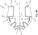
- FIG. 4B is a bottom plan view of clip 40.
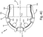
- FIG. 4C is a top plan view of clip 40.
- FIG. 4D is a side elevation view of clip 40.
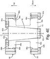
- FIG. 4E is a rear elevation view of clip 40.
- FIGS. 4A-4E will be discussed together. Relative up-down directions are indicated in FIG. 4A .
- Clip 40 includes top side 41, bottom side 43, top portion 48, bottom portion 50, spine 52, side opening 54, tabs 62a-62e, and plates 64a, 64b.
- Top portion 48 includes upper arms 56a, 56b.
- Upper arms 56a, 56b include guide surfaces 66a, 66b, respectively.
- Bottom portion 50 includes lower arms 58a, 58b.
- Lower arms 58a, 58b include guide surfaces 66c, 66d, respectively.
- Top portion 48 and bottom portion 50 are disposed at opposite axial ends of spine 52.
- Upper arms 56a, 56b and lower arms 58a, 58b extend from spine 23 and wrap partially, but not completely, around (e.g., circumferentially) a packing stack, such as packing stack 20 ( FIGS. 1-3C ).
- Each of top portion 48 and bottom portion 50 can be arcuate.
- each of upper arms 56a, 56b and lower arms 58a, 58b can also be arcuate.
- Each upper arm 56a, 56b extends from spine 52 such that each upper arm 56a, 56b is independent of any other arm extending from spine 52. As such, each upper arms 56a, 56b can be cantilevered from spine 52.
- each lower arm 58a, 58b extends from spine 52 such that each lower arm 58a, 58b is independent of any other arm extending from spine 52. As such, each lower arms 58a, 58b can be cantilevered from spine 52.
- each of upper arms 56a, 56b and each of lower arms 58a, 58b are free from the other arms and are not connected to the other arms, except by spine 52.
- Each of upper arms 56a, 56b and each of lower arms 58a, 58b independently extends from spine 52.
- Guide surfaces 66a-66d are flat surfaces that guide insertion of packings 36a, 36b ( FIGS. 1-3C ) and/or glands 34a, 34b ( FIGS. 1-3C ) into clip 20.
- guide surfaces 66a, 66b are formed by flat surfaces disposed at the distal ends 68a, 68b of curved upper arms 56a, 56b
- guide surfaces 66c, 66d are formed by flat surfaces disposed at the distal ends 68c, 68d of curved lower arms 58a, 58b.
- Side opening 54 extends between and is defined between guide surface 66a and guide surface 66b and between guide surface 66c and guide surface 66d.
- Tabs 62a-62e extend radially inward towards axis A-A ( FIGS. 3A-3C ) from top side 41 of clip 40 and bottom side 43 of clip 40. Tabs 62a-62e prevent axial or up and down movement of the elements of packing stack 20 relative to the clip 40. Tabs 62a-62c extend radially inward from the bottom side of clip 40. Tabs 62a, 62b extend from lower arms 58a, 58b, respectively. Tab 62c extends from spine 52. Tabs 62d, 62e extend from upper arms 56a, 56b, respectively.
- spine 52 is shown as including tab 62c on bottom side 43, it is understood that spine 52 can include a tab 62 on top side 41 or tabs 62 on both top side 41 and bottom side 43.
- lower arms 58a, 58b and upper arms 56a, 56b are each shown as including a single tab 62, it is understood that each of lower arms 58a, 58b and upper arms 56a, 56b can include more than one tab 62.
- some of lower arms 58a, 58b and upper arms 56a, 56b include no tabs 62 while others include one or more tabs 62.
- Tabs 62a-62e prevent axial movement of packing stack 20 relative to clip 40.
- Upper arms 56a, 56b and lower arms 58a, 58b prevent undesired sideways or lateral movement of the elements of packing stack 20 relative to clip 40.
- Plates 64a, 64b are disposed at distal ends 68a, 68b of upper arms 56a, 56b, respectively. Plates 64a, 64b extend radially inward from upper arms 56a, 56b. Plates 64a, 64b can function as tabs, similar to tabs 62a-62e, preventing axial (up and down) movement of the elements of packing stack 20 relative to clip 40. Plates 64a, 64b also guide insertion of packings 36a, 36b and/or glands 34a, 34b into clip 40.
- Side opening 54 provides a passageway through which the elements of packing stack 20 can be inserted into clip 40 to be securely captured within clip 40.
- side opening 54 is the only opening or space through which the elements of packing stack 20 can be inserted and/or removed from clip 40.
- side opening 54 is the only opening or space through which the whole assembled packing stack 20 can be inserted and/or removed from clip 40.
- side opening 54 is the only opening or space through which the individual packings 36a, 36b and/or glands 34a, 34b of packing stack 20 can be inserted and/or removed from clip 40.
- Side opening 54 has width W, shown in FIG. 4C , which widens and narrows on insertion and withdrawal of the elements of packing stack 20 through side opening 54.
- Upper arms 56a, 56b and lower arms 58a, 58b are configured to elastically flex as packing stack 20 passes into and out of clip 40.
- Width W of side opening 54 elastically widens during insertion of the elements of packing stack 20 into the center of clip 40.
- Width W of side opening 54 elastically narrows after the elements of packing stack 20 pass through side opening 54 and the elements are contained within clip 40 (e.g., coaxial with axis A-A). Such elastic narrowing due to spring force helps retain packing stack 20 within clip 40.
- Width W of side opening 54 elastically widens during passage of the elements of packing stack 20 through side opening 54 during removal of packing stack 20 from clip 40. Width W of side opening 54 elastically narrows after passage of the elements of packing stack 20 through side opening 54 during removal of packing stack 20 from clip 40.
- Tabs 62d, 62e and plates 64a, 64b engage the first stack end 42 ( FIGS. 2A-2C ) and tabs 62a-62c engage second stack end 44 ( FIGS. 2A-2C ) of packing stack 20 to prevent the elements of packing stack 20 from disengaging from clip 20 in either the up or down axial directions.
- tabs 62d, 62e and plates 64a, 64b are peripherally arrayed around a top side of clip 40 and extend radially inward toward axis A-A.
- Tabs 62d, 62e and plates 64a, 64b engage the top peripheral surface of packing stack 20 to contain packing stack 20 within clip 40.
- tabs 62a-62c are peripherally arrayed around a bottom side of clip 40 and extend radially inward toward axis A-A. Tabs 62a-62c engage the bottom peripheral surface of packing stack 20 to contain packing stack within clip 40.
- Tabs 62d, 62e and plates 64a, 64b on top portion 48 have a greater length than tabs 62a-62c on bottom portion 50, such that tabs 62d, 62d and plates 64a, 64b extend further toward axis A-A at the center of clip 40 than tabs 62a-62c.
- tabs 62a-62c do not overlap, cover, and/or block the bottom opening of central bore 46 (best seen in FIGS. 2B-3A ) through packing stack 20.
- central bore 46 of packing stack 20 is fully exposed through bottom portion 50 of clip 40 to allow insertion of piston rod 22 (best seen in FIGS.
- each of tabs 62d, 62e and plates 64a, 64b can also be referred to at a block that extends over and covers at least part of central bore 46. While top portion 48 includes one or more blocks, bottom portion 50 does not include a projection extending over and covering at least part of central bore 46, such that central bore 46 can be fully exposed through the opening through bottom portion 50.
- Packing stack 20 can be directionally oriented, with packings 36a, 36b and/or glands 34a, 34b having up and down orientations, such that packing stack 20 does not provide the desired sealing when installed in the incorrect, upside-down orientation.
- Clip 40 blocking one of the top or bottom openings of central bore 46, while exposing the other of the top or bottom openings, helps prevent packing stack 20 from being mounted on piston 12 in the incorrect orientation. For example, if the user attempts to install packing stack 20 from the incorrect orientation, tabs 62d, 62e and plates 64a, 64b interfere with and prevent piston 12 from entering into central bore 46 of packing stack 20.
- Clip 40 provides significant advantages. Tabs 62a-62e and plates 64a, 64b retain packing stack 20 on clip and prevent packing stack 20 from moving axially relative to clip 40.
- upper arms 56a, 56b and lower arms 58a, 58b extend around packing stack 20 and retain packing stack 20 on clip 40.
- Upper arms 56a, 56b and lower arms 58a, 58b are configured to elastically deform to allow packing stack 20 to slide in and out of side opening 54 while installing packing stack 20 in clip 40 or on piston rod 22, while otherwise retaining packing stack 20 within clip 40.
- assembly 38 is a standalone component that coaxially aligns the elements of packing stack 20 in the desired order for installation and maintains the elements in that desired order until installation.
- Clip 40 holds the elements of packing stack 20 in order and alignment prior to installation. Clip 40 further facilities installation by sliding packing stack 20 onto piston 12 and pulling away from packing stack 20 while maintaining packing stack 20 on piston 12. No additional tools besides assembly 38 are required to install packing stack 20 on piston 12.
Landscapes
- Engineering & Computer Science (AREA)
- General Engineering & Computer Science (AREA)
- Mechanical Engineering (AREA)
- Sealing Devices (AREA)
- Packages (AREA)
- Jigs For Machine Tools (AREA)
- Reciprocating Pumps (AREA)
Abstract
Description
- This application claims priority to
U.S. Provisional Application No. 62/649,003 filed on March 28, 2018 - The present disclosure relates to piston pumps, and in particular sealing elements within the pumps.
- Piston pumps are used to pump fluids, typically at high pressures. The pump elements disclosed herein are particularly well suited for pumping paint, finishes, and other coatings which are typically abrasive, viscous, and/or otherwise difficult to pump. Packings are used to facilitate forming a dynamic seal in such difficult to handle fluid applications.
- Packings are rings of sealing material. A packing can be formed from leather, rubber, polymer (e.g., ultra high molecular weight polyethylene or UHMWPE), and/or synthetic material. Packings commonly have complementary cross sections, such as having U or V cross section shapes, to mate and stack upon one another. Packings are typically arranged in a stack, such as six or more packing rings mounted atop one another. Packings of different types can be arranged in an alternating arrangement, such as leather-synthetic-leather-synthetic-leather-synthetic or other combination.
- Glands are rings (typically metal) which having complementally cross sectional profiles, such as having U or V projecting and recessed cross sectional shapes to mate and stack with the packings. A set of two glands are typically placed at both ends (top and bottom) of the stack of packings, bracketing the stack of packings. The glands can then be fixed to a component of the pump. The glands can retain the stack of packings within the pump.
- Packings are used as dynamic sealing surfaces in which the packings either move with the piston or the piston moves relative to the packings. For example, a stack of packings can be mounted on a piston rod such that the packings move with the piston rod and slide along the inner surface of the bore of the cylinder. In other examples, a stack of packings can be mounted on the inside bore of a cylinder and are held static relative to the cylinder while the piston slides along the packings. In both examples, the packings seal between the cylinder and the piston to prevent leakage of fluid past the packings between the cylinder and the piston. When packings are used with double displacement pumps, two stacks of packings are commonly used. A first set of packings seal along the pump rod of the piston, commonly known as throat packings. A second set of packings seal along the piston head of the piston, commonly known as piston packings.
- Packings can be difficult to handle and install, particularly when in a stacked arrangement. Within the pump, the packings are arranged coaxial and contacting one another, but can fall out of coaxial, contacting alignment when not secured in place. If one packing in a stack is not coaxially aligned with the rest of the packings in a stack, then the stack cannot be properly aligned within the cylinder and/or on the piston.
- According to one aspect of the disclosure, a clip for holding a stack of packing rings having a first stack end, a second stack end, and a central bore through both the first stack end and the second stack end, on a longitudinal axis. The clip includes a spine having a first end and a second end; a first bracket extending from the first end of the spine partially around the axis, the first bracket configured to hold the first stack end; and a second bracket extending from the second end of the spine partially around the axis, the second bracket configured to hold the second stack end. The first bracket and the second bracket define a side opening oriented to allow the packing stack to slide laterally relative to the axis and out from between the first bracket and the second bracket.
- According to another aspect of the disclosure, a method includes sliding a packing assembly in a first axial direction and onto an end of a piston for a reciprocating fluid pump. The packing assembly includes a clip having at least one bracket defining a side opening; and a packing stack retained on the clip and held in axial alignment on a longitudinal axis by the at least one bracket of the clip. The method further includes shifting the clip laterally relative to the piston to disengage the packing stack from the clip through the side opening leaving the packing stack disposed on the piston.
- According to yet another aspect of the disclosure, an assembly includes a packing stack formed from a plurality of packing rings dispose on a stack axis, and a clip configured to hold the packing stack. The packing stack includes a first stack end; a second stack end disposed opposite the first stack end; and a central bore extending through the plurality of packing rings between the first stack end and the second stack end. The clip includes a spine having a first end and a second end; a top portion extending partially around the axis from the first end of the spine; and a bottom portion extending partially around the axis from the second end of the spine. The top portion and the bottom portion define an axially extending side opening oriented to allow the packing stack to slide laterally relative to the axis into and out of an area defined between the top portion, the bottom portion, and the spine.
- According to an aspect of the present invention, there is provided 1. A clip for holding a stack of packing rings having a first stack end, a second stack end, and a central bore through both the first stack end and the second stack end, on a longitudinal axis, the clip comprising: a spine having a first end and a second end; a first bracket extending from the first end of the spine partially around the axis, the first bracket configured to hold the first stack end; and a second bracket extending from the second end of the spine partially around the axis, the second bracket configured to hold the second stack end; wherein the first bracket and the second bracket define a side opening oriented to allow the packing stack to slide laterally relative to the axis and out from between the first bracket and the second bracket.
- Preferably, the first bracket comprises a plurality of upper arms extending from opposite lateral sides of the spine, such that the plurality of upper arms at least partially define the side opening.
- Preferably, the plurality of upper arms include a first upper arm extending from a first lateral side of the spine and a second upper arm extending from a second lateral side of the spine, wherein the first upper arm and the second upper arm are configured to elastically deform to increase and decrease a width of the side opening, to thereby permit the stack of packing rings to slide laterally through the side opening.
- Preferably, wherein the second bracket comprises a plurality of lower arms extending from opposite lateral sides of the spine, such that the plurality of lower arms at least partially define the side opening.
- Preferably, the plurality of lower arms include a first lower arm extending from a first lateral side of the spine and a second lower arm extending from a second lateral side of the spine, wherein the first lower arm and the second lower arm are configured to elastically deform to increase and decrease a width of the side opening, to thereby permit the stack of packing rings to slide laterally through the side opening.
- Preferably, the side opening is disposed opposite the spine.
- Preferably, the spine is the only portion of the clip that connects the first bracket and the second bracket.
- Preferably, the first bracket defines a first end opening extending axially through the first bracket, such that the central opening of the stack of packing rings is exposed through the first end opening.
- Preferably, the second bracket defines a second end opening extending axially through the second bracket, such that the central opening of the stack of packing rings is exposed through the second end opening.
- Preferably, the first bracket further comprises at least one block projecting radially inward from the first bracket and into the first axial opening, the at least one block configured to extend over and cover at least part of the central bore of the stack of packing rings; and the second bracket does not include a projection extending over and covering at least part of the central bore, such the central bore is fully exposed through the second end opening.
- Preferably, the first bracket comprises: a plurality of arcuate upper arms extending from opposite lateral sides of the spine, such that distal ends of the plurality of arcuate upper arms at least partially define the side opening; the second bracket comprises: a plurality of arcuate lower arms extending from opposite lateral sides of the spine, such that distal ends of the plurality of arcuate lower arms at least partially define the side opening; and a first lower tab projecting radially from a first one of the plurality of arcuate lower arms, the first lower tab configured to engage the second stack end of the stack of packing rings to axially retain the stack of packing rings within the clip; the block extends from a first one of the plurality of arcuate upper arms.
- Preferably, the clip further comprises: a first guide plate disposed at a distal end of the first one of the plurality of arcuate upper arms, the first guide plate extending over the side opening; a first flat disposed below the first guide plate at the distal end of the first one of the plurality of arcuate upper arms; a second guide plate disposed at a distal end of a second one of the plurality of arcuate upper arms, the second guide plate extending over the side opening; and a second flat disposed below the second guide plate at the distal end of the second one of the plurality of arcuate upper arms; wherein the first flat is disposed across from and oriented towards the second flat such that the side opening is at least partially defined between the first flat and the second flat.
- According to another aspect of the present invention, there is provided an assembly comprising: a clip as set out above; and the packing stack mounted within the clip and retained within the clip by the first bracket and the second bracket.
- According to another aspect of the present invention, there is provided a method of loading a piston with the assembly set out above, the method comprising: axially aligning the stack of packing rings with an end of the piston; shifting the clip axially over the end of the piston such that the piston extends into the central bore of the stack of packing rings; and pulling the clip laterally relative to the piston and the stack of packing rings such that the stack of packing rings are released from the clip through the side opening of the clip while the stack of packing rings remain on the end of the piston.
- Preferably, the method comprises pulling the clip laterally relative to the piston comprises pulling the clip in a direction orthogonal to the axis.
- Preferably, the first bracket comprises a plurality of upper arms extending from opposite lateral sides of the spine, such that the plurality of upper arms at least partially define the side opening; the second bracket comprises a plurality of lower arms extending from opposite lateral sides of the spine, such that the plurality of lower arms at least partially define the side opening; and the plurality of upper arms and the plurality of lower arms flex to widen the side opening as the clip is pulled laterally relative to the piston.
- Preferably, the method comprises forming the stack of packing rings by: arranging a plurality of packings in a desired configuration; placing a first gland at a first end of the packings; and placing a second gland at a second end of the packings; aligning the packing stack with the side opening; and shifting the packing stack laterally through the side opening and into the clip.
- Preferably, the method comprises blocking a first end opening defined through the first bracket with at least one tab extending laterally towards the axis from the first bracket to prevent an object having a diameter approximately equal to a dimeter of the first end opening from passing through the first end opening.
- According to another aspect of the present invention, there is provided a method comprising: sliding a packing assembly in a first axial direction and onto an end of a piston for a reciprocating fluid pump, wherein the packing assembly comprises: a clip having at least one bracket defining a side opening; and a packing stack retained on the clip and held in axial alignment on a longitudinal axis by the at least one bracket of the clip; and shifting the clip laterally relative to the piston to disengage the packing stack from the clip through the side opening leaving the packing stack disposed on the piston.
- According to another aspect of the present invention, there is provided an assembly comprising: a packing stack formed from a plurality of packing rings dispose on a stack axis, the packing stack comprising: a first stack end; a second stack end disposed opposite the first stack end; and a central bore extending through the plurality of packing rings between the first stack end and the second stack end; and a clip configured to hold the packing stack, the clip comprising: a spine having a first end and a second end; a top portion extending partially around the axis from the first end of the spine; and a bottom portion extending partially around the axis from the second end of the spine; wherein the top portion and the bottom portion define an axially extending side opening oriented to allow the packing stack to slide laterally relative to the axis into and out of an area defined between the top portion, the bottom portion, and the spine.
- Embodiments of the present invention will now be described by way of further example only and with reference to the accompanying drawings, in which:
-
FIG. 1 is a cross-sectional view of a pump. -
FIG. 2A is an exploded view of a clip and packings assembly. -
FIG. 2B is a partially exploded view of the clip and packings assembly shown inFIG. 2A . -
FIG. 2C is an isometric view of the clip and packings assembly shown inFIG. 2B . -
FIG. 3A is a first isometric view of a piston rod and clip and packings assembly. -
FIG. 3B is a second isometric view of a piston rod and clip and packings assembly. -
FIG. 3C is a third isometric view of a piston rod and clip and packings assembly. -
FIG. 4A is an isometric view of a clip. -
FIG. 4B is a bottom plan view of the clip shown inFIG. 4A . -
FIG. 4C is a top plan view of the clip shown inFIG. 4A . -
FIG. 4D is a side elevation view of the clip shown inFIG. 4A . -
FIG. 4E is a front elevation view of the clip shown inFIG. 4A . -
FIG. 1 is a cross-sectional view ofpump 10.Pump 10 includespiston 12,cylinder 14,check valves nut 18, packingstack 20a, and packingstack 20b.Piston 12 includespiston rod 22 andpiston head 24.Piston rod 22 includesfirst end 26 andsecond end 28.First end 26 includesrod head 30.Intake housing 32 is disposed at a bottom ofcylinder 14.Packing stack 20a includesglands packings Packing stack 20b also includesglands packings -
Pump 10 reciprocatespiston 12 withincylinder 14 to pump various fluids, examples of which include paint, water, oil, stains, finishes, aggregate, coatings, and solvents, amongst other options.Pump 10 can generate high fluid pumping pressures, such as 3,000-5,000 pounds per square inch (psi) or even higher. High fluid pumping pressure is useful for atomizing the fluid into a spray for applying the fluid to a surface. -
Piston 12 is disposed withincylinder 14 and configured to reciprocate withincylinder 14.First end 26 extends out ofcylinder 14 throughthroat packings 20b.Rod head 30 is disposed outside ofcylinder 14 and is configured to connect to a drive system that drives reciprocation ofpiston 12.Piston head 24 is connected tosecond end 28 ofpiston rod 22.Piston head 24 can be connected topiston rod 22 in any desired manner, such as by interfaced threading or welding. In other examples,piston head 24 is integrally formed withpiston rod 22, such thatpiston rod 22 andpiston head 24 form a unitary assembly.Check valve 16b is disposed withinpiston rod 22. In the example shown,piston head 24 retainscheck valve 16b withinpiston rod 22. -
Intake housing 32 is connected to the bottom ofcylinder 14. In some examples,intake housing 32 is threadedly connected tocylinder 14. Checkvalve 16a is disposed withinintake housing 32 and forms a one-way check valve to allow fluid to flow downstream intointake housing 32 while preventing the fluid from flowing upstream out ofintake housing 32. - Retaining
nut 18 is located at an opposite end ofpump 10 fromintake housing 32. Retainingnut 18 is secured tocylinder 14 and is configured to retain packingstack 20b withincylinder 14. Retainingnut 18 can be secured tocylinder 14 in any desired manner, such as by interfaced threading.Packing stack 20b is disposed withincylinder 14.Piston rod 22 extends through packingstack 20b and can reciprocate relative to packingstack 20b. -
Packing stack 20b is configured to seal betweenpiston rod 22 and the inner wall ofcylinder 14.Packing stack 20a is disposed withincylinder 14 betweenpiston 12 andcylinder 14.Packing stack 20a is configured to seal betweenpiston 12 and the inner wall ofcylinder 14. -
Piston 12 reciprocates withincylinder 14 to increase and decrease the volumes of bothupstream chamber 15 anddownstream chamber 17. Increasing and decreasing the volumes ofupstream chamber 15 anddownstream chamber 17 draws fluid intocylinder 14 and pumps the fluid downstream out ofcylinder 14. During an upstroke,upstream chamber 15 expands creating suction and causingcheck valve 16a to open, whiledownstream chamber 17 shrinks, thereby causingcheck valve 16b to close and driving the fluid out ofdownstream chamber 17. During a downstroke,upstream chamber 15 shrinks, thereby causingcheck valve 16a to close, whiledownstream chamber 17 expands, openingcheck valve 16b and causing the fluid to flow fromupstream chamber 15 todownstream chamber 17 throughcheck valve 16b andpiston rod 22. The fluid entersdownstream chamber 17 throughoutlet 19 formed thoughpiston rod 22.Pump 10 can be a double displacement pump such thatpiston 12 drives fluid downstream out ofcylinder 14 during both the upstroke and the downstroke. - For each of packing
stack 20b and packingstack 20a,packings glands Packings glands piston 12 during reciprocation ofpiston 12.Packings Packings Packings Packings Glands stack 20b and packingstack 20a typically include one male gland, such asgland 34a, and one female gland, such asgland 34b, to complement the cross-sections ofpackings Packings glands -
FIG. 2A is an exploded view ofassembly 38.FIG. 2B is a partially exploded view ofassembly 38.FIG. 2C is an isometric view ofassembly 38.Assembly 38 includes packingstack 20 andclip 40.Packing stack 20 includesglands packings first stack end 42;second stack end 44; andcentral bore 46.Clip 40 includestop side 41,bottom side 43,top portion 48,bottom portion 50,spine 52, andside opening 54.Top portion 48 includesupper arms Bottom portion 50 includeslower arms -
Packings Glands packings Top portion 48 extends aroundtop side 41 ofclip 40.Top portion 48 can also be referred to as a bracket.Bottom portion 50 extends aroundbottom side 43 ofclip 40.Bottom portion 50 can also be referred to as a bracket. As shown,top portion 48 extends from a first axial end ofspine 52 andbottom portion 50 extends form a second axial end ofspine 52. In some examples,spine 52 is the only portion ofclip 40 that extends between and connectstop portion 48 andbottom portion 50. Each oftop portion 48 andbottom portion 50 can be arcuate, though it is understood that each oftop portion 48 andbottom portion 50 can be of any desired configuration for receiving and retaining packingstack 20.Upper arms spine 52.Lower arms spine 52.Side opening 54 is defined betweenupper arm 56a andupper arm 56b, and betweenlower arm 58a andlower arm 58b. - In
FIG. 2A ,packings glands packings clip 40,packings glands FIG. 2B , such thatpackings glands FIGS. 1 and3A-3C ). - From the arrangement shown in
FIG. 2B , the assembled packingstack 20 formed bypackings glands clip 40 to form the arrangement shown inFIG. 2C .Packing stack 20 is shifted laterally intoclip 40 throughside opening 54.Upper arms lower arms stack 20 passes ontoclip 40 throughside opening 54.Upper arms lower arms stack 20 onclip 40 once inserted.Upper arms lower arms stack 20 onclip 40 in the desired contacting and coaxial arrangement.Spine 52 can also flex in response to packingstack 20 passing throughside opening 54 and intoclip 40. -
Upper arms first stack end 42 to prevent packingstack 20 from shifting laterally. As discussed in more detail below,upper arms stack 20 relative to clip 40.Lower arms second stack end 44 to prevent packingstack 20 from shifting laterally. As discussed in more detail below,lower arms stack 20 relative to clip 40.Clip 40 preventspackings glands packings glands piston 12. Central bore 46 is exposed on both the top and bottom sides ofclip 40 to allow for insertion ofpiston 12 into packingstack 20 throughcentral bore 46 of packingstack 20. As such, a first end opening extends axially throughtop portion 48 such thatcentral bore 46 is exposed through the first end opening, and a second end opening extends axially throughbottom portion 50 such thatcentral bore 46 is exposed through the second end opening. -
FIG. 3A is a first isometric view ofpiston 12 andassembly 38.FIG. 3B is a second isometric view ofpiston rod 22 andassembly 38.FIG. 3C is a third isometric view ofpiston 12 andassembly 38.Piston rod 22 ofpiston 12 is shown.Piston rod 22 includesfirst end 26 andsecond end 28.Second end 28 includesshoulder 60.Assembly 38 includes packingstack 20 andclip 40. -
FIGS. 3A-3C illustrate the installation of packingstack 20 onpiston 12Assembly 38 is aligned withpiston rod 22 such thatsecond end 28 ofpiston rod 22 is coaxially aligned withcentral bore 46 through packingstack 20. Withpiston rod 22 andcentral bore 46 coaxially aligned,assembly 38 is moved in direction A (e.g., axially) from the position shown inFIG. 3A to the position shown inFIG. 3B such thatsecond end 28 is received withincentral bore 46.Gland 34a can contactshoulder 60 with packingstack 20 fully inserted ontopiston rod 22.Shoulder 60 can thereby provide a visual indication to the user that packingstack 20 is properly positioned, and can provide a physical stop ensuring that packingstack 20 is properly positioned. - With
assembly 38 disposed onpiston rod 22, piston head 24 (FIG. 1 ) can then be attached (e.g., by threading) topiston rod 22 to capture packingstack 20 onpiston rod 22. In some examples,clip 40 is configured such that apiston head 24 can be inserted betweenupper arms central bore 46 and then into the bore insecond end 28 ofpiston rod 22 withclip 40 still disposed on packingstack 20. As such,piston head 24 can connect topiston rod 22 withassembly 38 mounted onpiston rod 22, such thatpiston head 24 retains packingstack 20 onpiston rod 22 during removal ofclip 40. - With packing
stack 20 positioned onpiston rod 22,clip 40 can be pulled laterally relative topiston rod 22 to removeclip 40 from packingstack 20, while leaving packingstack 20 onpiston rod 22.Clip 40 can be pulled off of packingstack 20 in direction B (e.g., sideways) such that packingstack 20 is pulled throughside opening 54. In some examples, direction B is orthogonal to lateral axis A-A. In this way,clip 40 is not slid off of packingstack 20 in an axial direction along lateral axis A-A (i.e. parallel with lateral axis A-A). Rather, removal ofclip 40 from packingstack 20 causestop portion 48 andbottom portion 50, and specificallyupper arms lower arms upper arms lower arms stack 20 and then completely disengage from packingstack 20.Clip 40 thereby leavespackings glands piston head 24 attached to piston rod 22). As such,clip 40 can be moved axially (e.g., up and down parallel with axis A-A of piston 12) to place packingstack 20 onpiston 12, and then moved sideways (e.g., laterally, orthogonal to the axial direction) to removeclip 40 from over packingstack 20 while leaving packingstack 20 mounted onpiston 12. -
Clip 40 can be formed from plastic (e.g., UHMWPE, polyethylene) or metal (e.g., aluminum).Packing stack 20 can be snapped into place inclip 40 and can be unsnapped upon removal ofclip 40 from packingstack 20. Elastic strain within the body ofclip 40, such as betweenupper arms lower arms stack 20 in place and in coaxial alignment withinclip 40. -
Assembly 38 provides significant advantages. One benefit ofclip 40 is thatpackings glands stack 20 in a proper order prior to installation. For example, packingstack 20 can be packaged in clip 40 (e.g., in a box, sack, blister pack, clamshell, or other package) withpackings glands stack 20 can be pre-oiled prior to assembly onclip 40 and packaging for shipment. The user, upon opening the package, does not need to order and assemblepackings glands stack 20 on thepiston 12. Instead, clip 40 facilitates installation by allowing the user to slide the fully assembled packingstack 20 ontopiston 12 in a first direction (e.g, axially) and then removeclip 40 in a second direction (e.g., laterally) while maintaining packingstack 20 onpiston 12 in the desired position and configuration. -
FIG. 4A is an isometric view ofclip 40.FIG. 4B is a bottom plan view ofclip 40.FIG. 4C is a top plan view ofclip 40.FIG. 4D is a side elevation view ofclip 40.FIG. 4E is a rear elevation view ofclip 40.FIGS. 4A-4E will be discussed together. Relative up-down directions are indicated inFIG. 4A .Clip 40 includestop side 41,bottom side 43,top portion 48,bottom portion 50,spine 52,side opening 54,tabs 62a-62e, andplates Top portion 48 includesupper arms Upper arms guide surfaces Bottom portion 50 includeslower arms Lower arms guide surfaces clip 20 is symmetric left-to-right, so a left view indicates what would be equivalent in a right view. -
Top portion 48 andbottom portion 50 are disposed at opposite axial ends ofspine 52.Upper arms lower arms FIGS. 1-3C ). Each oftop portion 48 andbottom portion 50 can be arcuate. As such, each ofupper arms lower arms - Each
upper arm spine 52 such that eachupper arm spine 52. As such, eachupper arms spine 52. Similarly, eachlower arm spine 52 such that eachlower arm spine 52. As such, eachlower arms spine 52. As such, each ofupper arms lower arms spine 52. Each ofupper arms lower arms spine 52. - Guide surfaces 66a-66d are flat surfaces that guide insertion of
packings FIGS. 1-3C ) and/orglands FIGS. 1-3C ) intoclip 20. As shown,guide surfaces distal ends upper arms surfaces lower arms Side opening 54 extends between and is defined betweenguide surface 66a and guidesurface 66b and betweenguide surface 66c and guidesurface 66d. -
Tabs 62a-62e extend radially inward towards axis A-A (FIGS. 3A-3C ) fromtop side 41 ofclip 40 andbottom side 43 ofclip 40.Tabs 62a-62e prevent axial or up and down movement of the elements of packingstack 20 relative to theclip 40.Tabs 62a-62c extend radially inward from the bottom side ofclip 40.Tabs lower arms Tab 62c extends fromspine 52.Tabs upper arms spine 52 is shown as includingtab 62c onbottom side 43, it is understood thatspine 52 can include a tab 62 ontop side 41 or tabs 62 on bothtop side 41 andbottom side 43. Whilelower arms upper arms lower arms upper arms lower arms upper arms Tabs 62a-62e prevent axial movement of packingstack 20 relative to clip 40.Upper arms lower arms stack 20 relative to clip 40. -
Plates distal ends upper arms Plates upper arms Plates tabs 62a-62e, preventing axial (up and down) movement of the elements of packingstack 20 relative to clip 40.Plates packings glands clip 40. -
Side opening 54 provides a passageway through which the elements of packingstack 20 can be inserted intoclip 40 to be securely captured withinclip 40. In some examples,side opening 54 is the only opening or space through which the elements of packingstack 20 can be inserted and/or removed fromclip 40. In some cases,side opening 54 is the only opening or space through which the whole assembled packingstack 20 can be inserted and/or removed fromclip 40. In some cases,side opening 54 is the only opening or space through which theindividual packings glands stack 20 can be inserted and/or removed fromclip 40. -
Side opening 54 has width W, shown inFIG. 4C , which widens and narrows on insertion and withdrawal of the elements of packingstack 20 throughside opening 54.Upper arms lower arms stack 20 passes into and out ofclip 40. Width W ofside opening 54 elastically widens during insertion of the elements of packingstack 20 into the center ofclip 40. Width W ofside opening 54 elastically narrows after the elements of packingstack 20 pass throughside opening 54 and the elements are contained within clip 40 (e.g., coaxial with axis A-A). Such elastic narrowing due to spring force helps retain packingstack 20 withinclip 40. Width W ofside opening 54 elastically widens during passage of the elements of packingstack 20 through side opening 54 during removal of packingstack 20 fromclip 40. Width W ofside opening 54 elastically narrows after passage of the elements of packingstack 20 through side opening 54 during removal of packingstack 20 fromclip 40. -
Tabs plates FIGS. 2A-2C ) andtabs 62a-62c engage second stack end 44 (FIGS. 2A-2C ) of packingstack 20 to prevent the elements of packingstack 20 from disengaging fromclip 20 in either the up or down axial directions. Specifically,tabs plates clip 40 and extend radially inward toward axis A-A.Tabs plates stack 20 to contain packingstack 20 withinclip 40. Likewise,tabs 62a-62c are peripherally arrayed around a bottom side ofclip 40 and extend radially inward toward axis A-A.Tabs 62a-62c engage the bottom peripheral surface of packingstack 20 to contain packing stack withinclip 40. -
Tabs plates top portion 48 have a greater length thantabs 62a-62c onbottom portion 50, such thattabs plates clip 40 thantabs 62a-62c. When packingstack 12 is contained withinclip 40 and axially aligned with axis A-A,tabs 62a-62c do not overlap, cover, and/or block the bottom opening of central bore 46 (best seen inFIGS. 2B-3A ) through packingstack 20. As such,central bore 46 of packingstack 20 is fully exposed throughbottom portion 50 ofclip 40 to allow insertion of piston rod 22 (best seen inFIGS. 3A-3C ) intocentral bore 46 of packingstack 20 frombottom portion 50 ofclip 40, thereby facilitating mounting of packingstack 20 on piston 12 (FIG. 1 ). With packingstack 20 mounted withinclip 40 and axially aligned with axis A-A,tabs plates central bore 46 in packingstack 20.Tabs plates central bore 46 to prevent insertion ofpiston 12 through the top opening ofcentral bore 46 of packingstack 20. As such, each oftabs plates central bore 46. Whiletop portion 48 includes one or more blocks,bottom portion 50 does not include a projection extending over and covering at least part ofcentral bore 46, such thatcentral bore 46 can be fully exposed through the opening throughbottom portion 50. -
Packing stack 20 can be directionally oriented, withpackings glands stack 20 does not provide the desired sealing when installed in the incorrect, upside-down orientation.Clip 40 blocking one of the top or bottom openings ofcentral bore 46, while exposing the other of the top or bottom openings, helps prevent packingstack 20 from being mounted onpiston 12 in the incorrect orientation. For example, if the user attempts to install packingstack 20 from the incorrect orientation,tabs plates piston 12 from entering intocentral bore 46 of packingstack 20. -
Clip 40 provides significant advantages.Tabs 62a-62e andplates stack 20 on clip and prevent packingstack 20 from moving axially relative to clip 40. In addition,upper arms lower arms stack 20 and retain packingstack 20 onclip 40.Upper arms lower arms stack 20 to slide in and out ofside opening 54 while installing packingstack 20 inclip 40 or onpiston rod 22, while otherwise retaining packingstack 20 withinclip 40. As such,assembly 38 is a standalone component that coaxially aligns the elements of packingstack 20 in the desired order for installation and maintains the elements in that desired order until installation.Clip 40 holds the elements of packingstack 20 in order and alignment prior to installation.Clip 40 further facilities installation by sliding packingstack 20 ontopiston 12 and pulling away from packingstack 20 while maintaining packingstack 20 onpiston 12. No additional tools besidesassembly 38 are required to install packingstack 20 onpiston 12. - While the invention has been described with reference to an exemplary embodiment(s), it will be understood by those skilled in the art that various changes may be made and equivalents may be substituted for elements thereof without departing from the scope of the invention. In addition, many modifications may be made to adapt a particular situation or material to the teachings of the invention without departing from the essential scope thereof. Therefore, it is intended that the invention not be limited to the particular embodiment(s) disclosed, but that the invention will include all embodiments falling within the scope of the appended claims.
Claims (15)
- A clip for holding a stack of packing rings having a first stack end, a second stack end, and a central bore through both the first stack end and the second stack end, on a longitudinal axis, the clip comprising:a spine having a first end and a second end;a first bracket extending from the first end of the spine partially around the axis, the first bracket configured to hold the first stack end; anda second bracket extending from the second end of the spine partially around the axis, the second bracket configured to hold the second stack end;wherein the first bracket and the second bracket define a side opening oriented to allow the packing stack to slide laterally relative to the axis and out from between the first bracket and the second bracket.
- The clip of claim 1, wherein the first bracket comprises a plurality of upper arms extending from opposite lateral sides of the spine, such that the plurality of upper arms at least partially define the side opening.
- The clip of any one of claim 2, wherein the second bracket comprises a plurality of lower arms extending from opposite lateral sides of the spine, such that the plurality of lower arms at least partially define the side opening.
- The clip of claim 3, wherein:the plurality of upper arms include a first upper arm extending from a first lateral side of the spine and a second upper arm extending from a second lateral side of the spine, wherein the first upper arm and the second upper arm are configured to elastically deform to increase and decrease a width of the side opening, to thereby permit the stack of packing rings to slide laterally through the side opening; andthe plurality of lower arms include a first lower arm extending from a first lateral side of the spine and a second lower arm extending from a second lateral side of the spine, wherein the first lower arm and the second lower arm are configured to elastically deform to increase and decrease a width of the side opening, to thereby permit the stack of packing rings to slide laterally through the side opening.
- The clip of any preceding claim, wherein the side opening is disposed opposite the spine.
- The clip of any preceding claim, wherein the spine is the only portion of the clip that connects the first bracket and the second bracket.
- The clip of any preceding claim, wherein the first bracket defines a first end opening extending axially through the first bracket, such that the central opening of the stack of packing rings is exposed through the first end opening.
- The clip of claim 7, wherein:the first bracket further comprises at least one block projecting radially inward from the first bracket and into the first axial opening, the at least one block configured to extend over and cover at least part of the central bore of the stack of packing rings; andthe second bracket defines a second end opening extending axially through the second bracket and the second bracket does not include a projection extending over and covering at least part of the central bore, such the central bore is fully exposed through the second end opening.
- The clip of claim 8, wherein:the first bracket comprises:
a plurality of arcuate upper arms extending from opposite lateral sides of the spine, such that distal ends of the plurality of arcuate upper arms at least partially define the side opening;the second bracket comprises:a plurality of arcuate lower arms extending from opposite lateral sides of the spine, such that distal ends of the plurality of arcuate lower arms at least partially define the side opening; anda first lower tab projecting radially from a first one of the plurality of arcuate lower arms, the first lower tab configured to engage the second stack end of the stack of packing rings to axially retain the stack of packing rings within the clip;the block extends from a first one of the plurality of arcuate upper arms. - An assembly comprising:the clip of any preceding claim; andthe packing stack mounted within the clip and retained within the clip by the first bracket and the second bracket.
- A method of loading a piston with the assembly of claim 10, the method comprising:axially aligning the stack of packing rings with an end of the piston;shifting the clip axially over the end of the piston such that the piston extends into the central bore of the stack of packing rings; andpulling the clip laterally relative to the piston and the stack of packing rings such that the stack of packing rings are released from the clip through the side opening of the clip while the stack of packing rings remain on the end of the piston.
- The method of claim 11, wherein pulling the clip laterally relative to the piston comprises pulling the clip in a direction orthogonal to the axis.
- The method of any one of claims 11 or 12, wherein:the first bracket comprises a plurality of upper arms extending from opposite lateral sides of the spine, such that the plurality of upper arms at least partially define the side opening;the second bracket comprises a plurality of lower arms extending from opposite lateral sides of the spine, such that the plurality of lower arms at least partially define the side opening; andthe plurality of upper arms and the plurality of lower arms flex to widen the side opening as the clip is pulled laterally relative to the piston.
- The method of claim 11, further comprising:
blocking a first end opening defined through the first bracket with at least one tab extending laterally towards the axis from the first bracket to prevent an object having a diameter approximately equal to a dimeter of the first end opening from passing through the first end opening. - A method comprising:sliding a packing assembly in a first axial direction and onto an end of a piston for a reciprocating fluid pump, wherein the packing assembly comprises:a clip having at least one bracket defining a side opening; anda packing stack retained on the clip and held in axial alignment on a longitudinal axis by the at least one bracket of the clip; andshifting the clip laterally relative to the piston to disengage the packing stack from the clip through the side opening leaving the packing stack disposed on the piston.
Applications Claiming Priority (2)
| Application Number | Priority Date | Filing Date | Title |
|---|---|---|---|
| US201862649003P | 2018-03-28 | 2018-03-28 | |
| US16/352,561 US10989306B2 (en) | 2018-03-28 | 2019-03-13 | Packing stack carrier for paint and other fluid pumps |
Publications (2)
| Publication Number | Publication Date |
|---|---|
| EP3546745A1 true EP3546745A1 (en) | 2019-10-02 |
| EP3546745B1 EP3546745B1 (en) | 2021-08-18 |
Family
ID=66001055
Family Applications (1)
| Application Number | Title | Priority Date | Filing Date |
|---|---|---|---|
| EP19165912.7A Active EP3546745B1 (en) | 2018-03-28 | 2019-03-28 | Packing stack carrier for paint and other fluid pumps |
Country Status (7)
| Country | Link |
|---|---|
| US (1) | US10989306B2 (en) |
| EP (1) | EP3546745B1 (en) |
| KR (1) | KR20190113667A (en) |
| CN (2) | CN110318995B (en) |
| AU (1) | AU2019202113A1 (en) |
| RU (1) | RU2019108922A (en) |
| TW (1) | TW201942473A (en) |
Families Citing this family (3)
| Publication number | Priority date | Publication date | Assignee | Title |
|---|---|---|---|---|
| US10989306B2 (en) | 2018-03-28 | 2021-04-27 | Graco Minnesota Inc. | Packing stack carrier for paint and other fluid pumps |
| US11458605B2 (en) | 2018-03-28 | 2022-10-04 | Graco Minnesota Inc. | Packing insertion tool for paint and other fluid pumps |
| USD896280S1 (en) * | 2019-01-16 | 2020-09-15 | Graco Minnesota Inc. | Piston rod |
Citations (4)
| Publication number | Priority date | Publication date | Assignee | Title |
|---|---|---|---|---|
| EP0185753B1 (en) * | 1984-06-14 | 1992-08-26 | Pumptech N.V. | Packing assembly for use in a plunger bore |
| WO1998016742A1 (en) * | 1996-10-17 | 1998-04-23 | Binks Sames Corporation | Modular piston rod assembly with integrated high-wear components |
| EP0927825B1 (en) * | 1998-01-02 | 2004-09-22 | Graco Inc. | Torque clip and packing for a piston |
| WO2017034996A1 (en) * | 2015-08-21 | 2017-03-02 | Graco Minnesota Inc. | Packing stacks for piston pumps |
Family Cites Families (41)
| Publication number | Priority date | Publication date | Assignee | Title |
|---|---|---|---|---|
| US1956843A (en) | 1930-07-30 | 1934-05-01 | Elizabeth Wheeler | Means for installing packing in stuffing-boxes |
| US2037046A (en) | 1933-03-29 | 1936-04-14 | Ralph N Robertson | Cartridge packing |
| US2860535A (en) | 1956-02-20 | 1958-11-18 | Chicago Rawhide Mfg Co | Seal installation tool |
| US3030702A (en) | 1959-03-02 | 1962-04-24 | Chicago Rawhide Mfg Co | Seal installation tool |
| US3069178A (en) | 1959-09-22 | 1962-12-18 | Rosen Sidney | Sealing arrangement for a pump |
| DE1203548B (en) | 1960-12-01 | 1965-10-21 | Kugelfischer G Schaefer & Co | Cover sleeve made of elastic material for a unit provided with roller bearing parts |
| US3266347A (en) | 1964-07-16 | 1966-08-16 | Allen Products Inc | Seal installation and setting tool |
| US3357283A (en) | 1966-07-01 | 1967-12-12 | Gen Electric | Apparatus for replacement of seals |
| US3639972A (en) | 1968-11-27 | 1972-02-08 | Woodward Governor Co | Method of forming a valve structure with o-ring seals |
| US3588126A (en) | 1969-05-16 | 1971-06-28 | Crane Packing Co | Unit-type packing seal for shaft |
| GB1367733A (en) | 1972-04-04 | 1974-09-25 | Dental Mfg Eng Ltd | High speed turbines |
| US3946873A (en) | 1972-07-19 | 1976-03-30 | Unity Railway Supply Co., Inc. | Ab-type piston assembly shipping cover |
| US3861020A (en) | 1973-04-26 | 1975-01-21 | Caterpillar Tractor Co | Seal installing tool |
| US3942234A (en) | 1974-07-08 | 1976-03-09 | Kepler Larry A | Seal and bearing installation tool |
| US4141129A (en) | 1976-09-27 | 1979-02-27 | Martini Leonard J | O-ring insertion tool |
| US4615440A (en) | 1985-05-01 | 1986-10-07 | Stanadyne, Inc. | Tappet cartridge assembly container and applicator |
| US4610834A (en) | 1985-09-26 | 1986-09-09 | Hydril Company | Apparatus and method for installing internal annular rings in tubular box members |
| US4719684A (en) | 1986-09-30 | 1988-01-19 | The Boeing Company | Apparatus for inserting seals into internal grooves of valve bores |
| DE4100045C1 (en) | 1991-01-03 | 1992-07-16 | Firma Kunstoffroehren-Sendenhorst, 4415 Sendenhorst, De | Sealing ring inserting mechanism into tube inner grooves - has hollow cylindrical slider with slits from front side adjacent to sealing ring |
| ES2083172T3 (en) | 1991-05-30 | 1996-04-01 | Crocodile Packaging Ltd | FOLDABLE PACKAGING CONTAINER. |
| US5228842A (en) | 1991-07-30 | 1993-07-20 | Wagner Spray Tech Corporation | Quick-change fluid section for piston-type paint pumps |
| JP2970671B2 (en) | 1997-11-07 | 1999-11-02 | 東海ゴム工業株式会社 | Protective cap for banjo member used in banjo-type joint and hose with banjo-type joint fitted with protect cap |
| US6212998B1 (en) | 1998-01-02 | 2001-04-10 | Graco Minnesota Inc. | Packings on pump rod |
| US6318551B1 (en) | 1999-11-10 | 2001-11-20 | Caterpillar Inc. | Method and apparatus for installing a prepackaged piston assembly in an engine |
| US20030084556A1 (en) | 2001-11-06 | 2003-05-08 | Dunlop Roy J | Pump plunger installation tool |
| DE102005001225B4 (en) | 2005-01-10 | 2012-10-25 | Sim Automation Gmbh & Co. Kg | Method and device for mounting internal O-rings |
| US7690505B2 (en) | 2006-05-30 | 2010-04-06 | Gunite Corporation | Wheel hub shipping retainer system |
| US20080301924A1 (en) | 2007-06-05 | 2008-12-11 | Jeff Jarrett | Combined tamping tool and packing follower |
| US8001995B2 (en) | 2008-06-23 | 2011-08-23 | Gregory Molloy | End cap for a hydraulic fitting |
| US8616555B2 (en) | 2008-10-13 | 2013-12-31 | Schlumberger Technology Corporation | Packing assembly for reciprocating pumps |
| US8079413B2 (en) | 2008-12-23 | 2011-12-20 | W. Lynn Frazier | Bottom set downhole plug |
| WO2010151676A1 (en) | 2009-06-24 | 2010-12-29 | Zest Ip Holdings Llc | O-ring insertion tool and method |
| US8640314B2 (en) | 2010-08-03 | 2014-02-04 | Federal-Mogul Corporation | Piston assembly transportation and installation apparatus and methods of transporting and installing a piston assembly therewith |
| CN202607576U (en) | 2012-05-23 | 2012-12-19 | 广西玉柴机器股份有限公司 | Tool for assembling sealing ring of exhaust pipe of engine |
| WO2014189792A1 (en) | 2013-05-20 | 2014-11-27 | Teadit N.A., Inc. | Compressible packing live loading apparatus |
| US9511486B2 (en) | 2014-03-19 | 2016-12-06 | Deere & Company | Seal installation guide sleeve |
| CN103991055B (en) | 2014-05-16 | 2015-10-28 | 安徽江淮汽车股份有限公司 | A kind of cylinder holes inner seal ring erecting device |
| CH709894A1 (en) | 2014-07-25 | 2016-01-29 | Fives Cryomec Ag | Reciprocating piston pump for cryogenic fluids. |
| CN107598830A (en) | 2017-10-31 | 2018-01-19 | 广西玉柴机器股份有限公司 | The method and device of O-ring seal in a kind of mounting hole |
| CN107806440A (en) | 2017-12-16 | 2018-03-16 | 山东双轮股份有限公司 | It is convenient for changing the axle sleeve structure of filler |
| US10989306B2 (en) | 2018-03-28 | 2021-04-27 | Graco Minnesota Inc. | Packing stack carrier for paint and other fluid pumps |
-
2019
- 2019-03-13 US US16/352,561 patent/US10989306B2/en active Active
- 2019-03-26 CN CN201910232875.7A patent/CN110318995B/en active Active
- 2019-03-26 CN CN201920396277.9U patent/CN210164624U/en not_active Withdrawn - After Issue
- 2019-03-27 TW TW108110690A patent/TW201942473A/en unknown
- 2019-03-27 AU AU2019202113A patent/AU2019202113A1/en not_active Abandoned
- 2019-03-27 RU RU2019108922A patent/RU2019108922A/en unknown
- 2019-03-28 KR KR1020190035746A patent/KR20190113667A/en not_active Withdrawn
- 2019-03-28 EP EP19165912.7A patent/EP3546745B1/en active Active
Patent Citations (4)
| Publication number | Priority date | Publication date | Assignee | Title |
|---|---|---|---|---|
| EP0185753B1 (en) * | 1984-06-14 | 1992-08-26 | Pumptech N.V. | Packing assembly for use in a plunger bore |
| WO1998016742A1 (en) * | 1996-10-17 | 1998-04-23 | Binks Sames Corporation | Modular piston rod assembly with integrated high-wear components |
| EP0927825B1 (en) * | 1998-01-02 | 2004-09-22 | Graco Inc. | Torque clip and packing for a piston |
| WO2017034996A1 (en) * | 2015-08-21 | 2017-03-02 | Graco Minnesota Inc. | Packing stacks for piston pumps |
Also Published As
| Publication number | Publication date |
|---|---|
| CN110318995A (en) | 2019-10-11 |
| EP3546745B1 (en) | 2021-08-18 |
| AU2019202113A1 (en) | 2019-10-17 |
| KR20190113667A (en) | 2019-10-08 |
| CN110318995B (en) | 2021-06-08 |
| US10989306B2 (en) | 2021-04-27 |
| RU2019108922A (en) | 2020-09-28 |
| US20190301615A1 (en) | 2019-10-03 |
| TW201942473A (en) | 2019-11-01 |
| CN210164624U (en) | 2020-03-20 |
Similar Documents
| Publication | Publication Date | Title |
|---|---|---|
| TWI795544B (en) | Packing holder, packing kit, packing insertion tool, method of installing a packing stack within a cylinder of a pump, and packing insertion kit | |
| EP3546745B1 (en) | Packing stack carrier for paint and other fluid pumps | |
| US8333386B2 (en) | Seal structure for connection sections and seal member used for the same | |
| CN1582254A (en) | Valve units for filling machines | |
| EP1218658A2 (en) | Tube fitting | |
| JP2008511794A (en) | Low friction reciprocating pump | |
| CN104896174A (en) | Apparatus to interface with a corrugated diaphragm | |
| EP3707418B1 (en) | Methods and apparatus to install valve packing components | |
| US11149728B2 (en) | Pump plunger protective packaging | |
| JP2018519468A (en) | Membrane pump | |
| CN105526391B (en) | Control valve for fluids | |
| JP6807931B2 (en) | Active surge chamber | |
| EP2390541A1 (en) | Ball valve device and method for forming a ball retainer in a check valve | |
| CN213808291U (en) | Multistage speed regulation hydraulic cylinder | |
| US20200318739A1 (en) | Bulk unloader follower seal | |
| CN223215791U (en) | Gate valve, gas distribution device and substrate processing device | |
| KR20190037564A (en) | Piston pump for break |
Legal Events
| Date | Code | Title | Description |
|---|---|---|---|
| PUAI | Public reference made under article 153(3) epc to a published international application that has entered the european phase |
Free format text: ORIGINAL CODE: 0009012 |
|
| STAA | Information on the status of an ep patent application or granted ep patent |
Free format text: STATUS: THE APPLICATION HAS BEEN PUBLISHED |
|
| AK | Designated contracting states |
Kind code of ref document: A1 Designated state(s): AL AT BE BG CH CY CZ DE DK EE ES FI FR GB GR HR HU IE IS IT LI LT LU LV MC MK MT NL NO PL PT RO RS SE SI SK SM TR |
|
| AX | Request for extension of the european patent |
Extension state: BA ME |
|
| STAA | Information on the status of an ep patent application or granted ep patent |
Free format text: STATUS: REQUEST FOR EXAMINATION WAS MADE |
|
| 17P | Request for examination filed |
Effective date: 20200327 |
|
| RBV | Designated contracting states (corrected) |
Designated state(s): AL AT BE BG CH CY CZ DE DK EE ES FI FR GB GR HR HU IE IS IT LI LT LU LV MC MK MT NL NO PL PT RO RS SE SI SK SM TR |
|
| GRAP | Despatch of communication of intention to grant a patent |
Free format text: ORIGINAL CODE: EPIDOSNIGR1 |
|
| STAA | Information on the status of an ep patent application or granted ep patent |
Free format text: STATUS: GRANT OF PATENT IS INTENDED |
|
| RIC1 | Information provided on ipc code assigned before grant |
Ipc: F04B 53/14 20060101ALI20210223BHEP Ipc: F04B 15/02 20060101ALI20210223BHEP Ipc: F04B 1/0408 20200101ALI20210223BHEP Ipc: F04B 53/16 20060101ALI20210223BHEP Ipc: F04B 1/04 20200101AFI20210223BHEP |
|
| INTG | Intention to grant announced |
Effective date: 20210318 |
|
| RIN1 | Information on inventor provided before grant (corrected) |
Inventor name: LEGATT, AUGUST F Inventor name: HORNING, JEROMY D |
|
| GRAS | Grant fee paid |
Free format text: ORIGINAL CODE: EPIDOSNIGR3 |
|
| GRAA | (expected) grant |
Free format text: ORIGINAL CODE: 0009210 |
|
| STAA | Information on the status of an ep patent application or granted ep patent |
Free format text: STATUS: THE PATENT HAS BEEN GRANTED |
|
| AK | Designated contracting states |
Kind code of ref document: B1 Designated state(s): AL AT BE BG CH CY CZ DE DK EE ES FI FR GB GR HR HU IE IS IT LI LT LU LV MC MK MT NL NO PL PT RO RS SE SI SK SM TR |
|
| REG | Reference to a national code |
Ref country code: GB Ref legal event code: FG4D |
|
| REG | Reference to a national code |
Ref country code: CH Ref legal event code: EP |
|
| REG | Reference to a national code |
Ref country code: DE Ref legal event code: R096 Ref document number: 602019006894 Country of ref document: DE |
|
| REG | Reference to a national code |
Ref country code: IE Ref legal event code: FG4D Ref country code: AT Ref legal event code: REF Ref document number: 1421873 Country of ref document: AT Kind code of ref document: T Effective date: 20210915 |
|
| REG | Reference to a national code |
Ref country code: LT Ref legal event code: MG9D |
|
| REG | Reference to a national code |
Ref country code: NL Ref legal event code: MP Effective date: 20210818 |
|
| REG | Reference to a national code |
Ref country code: AT Ref legal event code: MK05 Ref document number: 1421873 Country of ref document: AT Kind code of ref document: T Effective date: 20210818 |
|
| PG25 | Lapsed in a contracting state [announced via postgrant information from national office to epo] |
Ref country code: LT Free format text: LAPSE BECAUSE OF FAILURE TO SUBMIT A TRANSLATION OF THE DESCRIPTION OR TO PAY THE FEE WITHIN THE PRESCRIBED TIME-LIMIT Effective date: 20210818 Ref country code: BG Free format text: LAPSE BECAUSE OF FAILURE TO SUBMIT A TRANSLATION OF THE DESCRIPTION OR TO PAY THE FEE WITHIN THE PRESCRIBED TIME-LIMIT Effective date: 20211118 Ref country code: AT Free format text: LAPSE BECAUSE OF FAILURE TO SUBMIT A TRANSLATION OF THE DESCRIPTION OR TO PAY THE FEE WITHIN THE PRESCRIBED TIME-LIMIT Effective date: 20210818 Ref country code: HR Free format text: LAPSE BECAUSE OF FAILURE TO SUBMIT A TRANSLATION OF THE DESCRIPTION OR TO PAY THE FEE WITHIN THE PRESCRIBED TIME-LIMIT Effective date: 20210818 Ref country code: PT Free format text: LAPSE BECAUSE OF FAILURE TO SUBMIT A TRANSLATION OF THE DESCRIPTION OR TO PAY THE FEE WITHIN THE PRESCRIBED TIME-LIMIT Effective date: 20211220 Ref country code: NO Free format text: LAPSE BECAUSE OF FAILURE TO SUBMIT A TRANSLATION OF THE DESCRIPTION OR TO PAY THE FEE WITHIN THE PRESCRIBED TIME-LIMIT Effective date: 20211118 Ref country code: ES Free format text: LAPSE BECAUSE OF FAILURE TO SUBMIT A TRANSLATION OF THE DESCRIPTION OR TO PAY THE FEE WITHIN THE PRESCRIBED TIME-LIMIT Effective date: 20210818 Ref country code: FI Free format text: LAPSE BECAUSE OF FAILURE TO SUBMIT A TRANSLATION OF THE DESCRIPTION OR TO PAY THE FEE WITHIN THE PRESCRIBED TIME-LIMIT Effective date: 20210818 Ref country code: SE Free format text: LAPSE BECAUSE OF FAILURE TO SUBMIT A TRANSLATION OF THE DESCRIPTION OR TO PAY THE FEE WITHIN THE PRESCRIBED TIME-LIMIT Effective date: 20210818 Ref country code: RS Free format text: LAPSE BECAUSE OF FAILURE TO SUBMIT A TRANSLATION OF THE DESCRIPTION OR TO PAY THE FEE WITHIN THE PRESCRIBED TIME-LIMIT Effective date: 20210818 |
|
| PG25 | Lapsed in a contracting state [announced via postgrant information from national office to epo] |
Ref country code: PL Free format text: LAPSE BECAUSE OF FAILURE TO SUBMIT A TRANSLATION OF THE DESCRIPTION OR TO PAY THE FEE WITHIN THE PRESCRIBED TIME-LIMIT Effective date: 20210818 Ref country code: LV Free format text: LAPSE BECAUSE OF FAILURE TO SUBMIT A TRANSLATION OF THE DESCRIPTION OR TO PAY THE FEE WITHIN THE PRESCRIBED TIME-LIMIT Effective date: 20210818 Ref country code: GR Free format text: LAPSE BECAUSE OF FAILURE TO SUBMIT A TRANSLATION OF THE DESCRIPTION OR TO PAY THE FEE WITHIN THE PRESCRIBED TIME-LIMIT Effective date: 20211119 |
|
| PG25 | Lapsed in a contracting state [announced via postgrant information from national office to epo] |
Ref country code: NL Free format text: LAPSE BECAUSE OF FAILURE TO SUBMIT A TRANSLATION OF THE DESCRIPTION OR TO PAY THE FEE WITHIN THE PRESCRIBED TIME-LIMIT Effective date: 20210818 |
|
| PG25 | Lapsed in a contracting state [announced via postgrant information from national office to epo] |
Ref country code: DK Free format text: LAPSE BECAUSE OF FAILURE TO SUBMIT A TRANSLATION OF THE DESCRIPTION OR TO PAY THE FEE WITHIN THE PRESCRIBED TIME-LIMIT Effective date: 20210818 |
|
| REG | Reference to a national code |
Ref country code: DE Ref legal event code: R097 Ref document number: 602019006894 Country of ref document: DE |
|
| PG25 | Lapsed in a contracting state [announced via postgrant information from national office to epo] |
Ref country code: SM Free format text: LAPSE BECAUSE OF FAILURE TO SUBMIT A TRANSLATION OF THE DESCRIPTION OR TO PAY THE FEE WITHIN THE PRESCRIBED TIME-LIMIT Effective date: 20210818 Ref country code: SK Free format text: LAPSE BECAUSE OF FAILURE TO SUBMIT A TRANSLATION OF THE DESCRIPTION OR TO PAY THE FEE WITHIN THE PRESCRIBED TIME-LIMIT Effective date: 20210818 Ref country code: RO Free format text: LAPSE BECAUSE OF FAILURE TO SUBMIT A TRANSLATION OF THE DESCRIPTION OR TO PAY THE FEE WITHIN THE PRESCRIBED TIME-LIMIT Effective date: 20210818 Ref country code: EE Free format text: LAPSE BECAUSE OF FAILURE TO SUBMIT A TRANSLATION OF THE DESCRIPTION OR TO PAY THE FEE WITHIN THE PRESCRIBED TIME-LIMIT Effective date: 20210818 Ref country code: CZ Free format text: LAPSE BECAUSE OF FAILURE TO SUBMIT A TRANSLATION OF THE DESCRIPTION OR TO PAY THE FEE WITHIN THE PRESCRIBED TIME-LIMIT Effective date: 20210818 Ref country code: AL Free format text: LAPSE BECAUSE OF FAILURE TO SUBMIT A TRANSLATION OF THE DESCRIPTION OR TO PAY THE FEE WITHIN THE PRESCRIBED TIME-LIMIT Effective date: 20210818 |
|
| PGFP | Annual fee paid to national office [announced via postgrant information from national office to epo] |
Ref country code: FR Payment date: 20220325 Year of fee payment: 4 |
|
| PLBE | No opposition filed within time limit |
Free format text: ORIGINAL CODE: 0009261 |
|
| STAA | Information on the status of an ep patent application or granted ep patent |
Free format text: STATUS: NO OPPOSITION FILED WITHIN TIME LIMIT |
|
| 26N | No opposition filed |
Effective date: 20220519 |
|
| PG25 | Lapsed in a contracting state [announced via postgrant information from national office to epo] |
Ref country code: IT Free format text: LAPSE BECAUSE OF FAILURE TO SUBMIT A TRANSLATION OF THE DESCRIPTION OR TO PAY THE FEE WITHIN THE PRESCRIBED TIME-LIMIT Effective date: 20210818 |
|
| PG25 | Lapsed in a contracting state [announced via postgrant information from national office to epo] |
Ref country code: SI Free format text: LAPSE BECAUSE OF FAILURE TO SUBMIT A TRANSLATION OF THE DESCRIPTION OR TO PAY THE FEE WITHIN THE PRESCRIBED TIME-LIMIT Effective date: 20210818 |
|
| PG25 | Lapsed in a contracting state [announced via postgrant information from national office to epo] |
Ref country code: MC Free format text: LAPSE BECAUSE OF FAILURE TO SUBMIT A TRANSLATION OF THE DESCRIPTION OR TO PAY THE FEE WITHIN THE PRESCRIBED TIME-LIMIT Effective date: 20210818 |
|
| REG | Reference to a national code |
Ref country code: CH Ref legal event code: PL |
|
| REG | Reference to a national code |
Ref country code: BE Ref legal event code: MM Effective date: 20220331 |
|
| PG25 | Lapsed in a contracting state [announced via postgrant information from national office to epo] |
Ref country code: LU Free format text: LAPSE BECAUSE OF NON-PAYMENT OF DUE FEES Effective date: 20220328 Ref country code: LI Free format text: LAPSE BECAUSE OF NON-PAYMENT OF DUE FEES Effective date: 20220331 Ref country code: IE Free format text: LAPSE BECAUSE OF NON-PAYMENT OF DUE FEES Effective date: 20220328 Ref country code: CH Free format text: LAPSE BECAUSE OF NON-PAYMENT OF DUE FEES Effective date: 20220331 |
|
| PG25 | Lapsed in a contracting state [announced via postgrant information from national office to epo] |
Ref country code: BE Free format text: LAPSE BECAUSE OF NON-PAYMENT OF DUE FEES Effective date: 20220331 |
|
| P01 | Opt-out of the competence of the unified patent court (upc) registered |
Effective date: 20230531 |
|
| PG25 | Lapsed in a contracting state [announced via postgrant information from national office to epo] |
Ref country code: FR Free format text: LAPSE BECAUSE OF NON-PAYMENT OF DUE FEES Effective date: 20230331 |
|
| PG25 | Lapsed in a contracting state [announced via postgrant information from national office to epo] |
Ref country code: MK Free format text: LAPSE BECAUSE OF FAILURE TO SUBMIT A TRANSLATION OF THE DESCRIPTION OR TO PAY THE FEE WITHIN THE PRESCRIBED TIME-LIMIT Effective date: 20210818 Ref country code: CY Free format text: LAPSE BECAUSE OF FAILURE TO SUBMIT A TRANSLATION OF THE DESCRIPTION OR TO PAY THE FEE WITHIN THE PRESCRIBED TIME-LIMIT Effective date: 20210818 |
|
| PG25 | Lapsed in a contracting state [announced via postgrant information from national office to epo] |
Ref country code: HU Free format text: LAPSE BECAUSE OF FAILURE TO SUBMIT A TRANSLATION OF THE DESCRIPTION OR TO PAY THE FEE WITHIN THE PRESCRIBED TIME-LIMIT; INVALID AB INITIO Effective date: 20190328 |
|
| PG25 | Lapsed in a contracting state [announced via postgrant information from national office to epo] |
Ref country code: MT Free format text: LAPSE BECAUSE OF FAILURE TO SUBMIT A TRANSLATION OF THE DESCRIPTION OR TO PAY THE FEE WITHIN THE PRESCRIBED TIME-LIMIT Effective date: 20210818 |
|
| PG25 | Lapsed in a contracting state [announced via postgrant information from national office to epo] |
Ref country code: TR Free format text: LAPSE BECAUSE OF FAILURE TO SUBMIT A TRANSLATION OF THE DESCRIPTION OR TO PAY THE FEE WITHIN THE PRESCRIBED TIME-LIMIT Effective date: 20210818 |
|
| PGFP | Annual fee paid to national office [announced via postgrant information from national office to epo] |
Ref country code: GB Payment date: 20260327 Year of fee payment: 8 |
|
| PGFP | Annual fee paid to national office [announced via postgrant information from national office to epo] |
Ref country code: DE Payment date: 20260327 Year of fee payment: 8 |