EP3546651A1 - Roadway boundary block and road structure - Google Patents
Roadway boundary block and road structure Download PDFInfo
- Publication number
- EP3546651A1 EP3546651A1 EP17874386.0A EP17874386A EP3546651A1 EP 3546651 A1 EP3546651 A1 EP 3546651A1 EP 17874386 A EP17874386 A EP 17874386A EP 3546651 A1 EP3546651 A1 EP 3546651A1
- Authority
- EP
- European Patent Office
- Prior art keywords
- roadway
- region
- boundary block
- curbstone
- road
- Prior art date
- Legal status (The legal status is an assumption and is not a legal conclusion. Google has not performed a legal analysis and makes no representation as to the accuracy of the status listed.)
- Granted
Links
Images




Classifications
-
- E—FIXED CONSTRUCTIONS
- E01—CONSTRUCTION OF ROADS, RAILWAYS, OR BRIDGES
- E01C—CONSTRUCTION OF, OR SURFACES FOR, ROADS, SPORTS GROUNDS, OR THE LIKE; MACHINES OR AUXILIARY TOOLS FOR CONSTRUCTION OR REPAIR
- E01C11/00—Details of pavings
- E01C11/22—Gutters; Kerbs ; Surface drainage of streets, roads or like traffic areas
- E01C11/221—Kerbs or like edging members, e.g. flush kerbs, shoulder retaining means ; Joint members, connecting or load-transfer means specially for kerbs
- E01C11/222—Raised kerbs, e.g. for sidewalks ; Integrated or portable means for facilitating ascent or descent
-
- E—FIXED CONSTRUCTIONS
- E01—CONSTRUCTION OF ROADS, RAILWAYS, OR BRIDGES
- E01C—CONSTRUCTION OF, OR SURFACES FOR, ROADS, SPORTS GROUNDS, OR THE LIKE; MACHINES OR AUXILIARY TOOLS FOR CONSTRUCTION OR REPAIR
- E01C11/00—Details of pavings
- E01C11/22—Gutters; Kerbs ; Surface drainage of streets, roads or like traffic areas
- E01C11/221—Kerbs or like edging members, e.g. flush kerbs, shoulder retaining means ; Joint members, connecting or load-transfer means specially for kerbs
- E01C11/223—Kerb-and-gutter structures; Kerbs with drainage openings channel or conduits, e.g. with out- or inlets, with integral gutter or with channel formed into the kerb ; Kerbs adapted to house cables or pipes, or to form conduits
-
- Y—GENERAL TAGGING OF NEW TECHNOLOGICAL DEVELOPMENTS; GENERAL TAGGING OF CROSS-SECTIONAL TECHNOLOGIES SPANNING OVER SEVERAL SECTIONS OF THE IPC; TECHNICAL SUBJECTS COVERED BY FORMER USPC CROSS-REFERENCE ART COLLECTIONS [XRACs] AND DIGESTS
- Y02—TECHNOLOGIES OR APPLICATIONS FOR MITIGATION OR ADAPTATION AGAINST CLIMATE CHANGE
- Y02A—TECHNOLOGIES FOR ADAPTATION TO CLIMATE CHANGE
- Y02A30/00—Adapting or protecting infrastructure or their operation
- Y02A30/60—Planning or developing urban green infrastructure
Definitions
- the present invention relates to a roadway boundary block and arranged at a boundary of a roadway and relates to a road structure.
- a curbstone having a special configuration is provided.
- Patent Literature 1 two curved inclined portions are formed in a height direction of a curbstone. With this, an interference with a side wall of a tire is suppressed by a lower inclined portion and contact with a vehicle (body) is avoided by an upper inclined portion.
- an object of the present invention is, in consideration of the problem described above, to provide a roadway boundary block and a road structure capable of improving precision docking to a stop easily without depending on high driving ability of a driver.
- a roadway boundary block (for example, roadway boundary block 100) according to one aspect of the present invention includes a base portion (base portion 110) having an upper portion (upper portion 120) arranged to be continued to a roadway (roadway 10), and a curbstone portion (curbstone portion 150) raised from one end side of the base portion.
- An incline of the upper portion against a horizontal direction is larger than an incline of the roadway against the horizontal direction in a road width direction.
- a width (L1) of the upper portion along the road width direction is larger than a tire ground contact width of a vehicle (bus 50) travelling on the roadway and smaller than a tread of the vehicle.
- a road structure includes a roadway (roadway 10) on which a vehicle travels, and a curbstone (for example, curbstone 150A) arranged at a boundary of the roadway to form a level difference against the roadway.
- a road side portion (road side portion 12) continued to the roadway is arranged between the roadway and the curbstone.
- An incline of the road side portion against a horizontal direction is larger an incline of the roadway against the horizontal direction in a road width direction.
- a width of the road side portion along the road width direction is larger than a tire ground contact width of the vehicle travelling on the roadway and smaller than a tread of the vehicle.
- Fig. 1 shows one example of a road structure. Specifically, Fig. 1 is a plane view of the road structure including a roadway 10 and a sidewalk 20.
- the roadway 10 is a road for vehicles travelling thereon.
- the sidewalk 20 is a road for pedestrians.
- the sidewalk 20 is higher in level (15 cm to 30 cm) than the roadway 10.
- a stop 30 where a passenger gets on/off a bus 50 is arranged on a part of the sidewalk 20.
- the bus 50 is one of vehicles travelling on the roadway 10.
- the bus 50 is provided with a left front tire 51L, a right front tire 51R, a left rear tire 52L and a right rear tire 52R.
- a so-called double tire in which two tires are assembled in parallel is adopted in each of the left rear tire 52L and the right rear tire 52R.
- a type of the bus 50 is not especially limited, and therefore examples of the bus 50 include the following types of buses.
- a length is approximately 10 m to 11 m and a width is approximately 2.5 m
- a front wheel tread is approximately 2.0 m
- a rear wheel (double tires) tread is approximately 1.8 m.
- a size of the tires (front tire and rear tire) to be mounted is, for example, 275/70R22.5.
- a tread (ground contact width) of the tire is approximately 208 mm to 258 mm, which depends on a kind of tire.
- a length is approximately 10 m and a width is approximately 2.3 m, and a front wheel tread is approximately 1.9 m and a rear wheel (double tires) tread is approximately 1.7 m.
- a size of the tires (front tire and rear tire) to be mounted is, for example, 245/70R19.5.
- a tread (ground contact width) of the tire is approximately 203 mm to 223 mm, which depends on a kind of tire.
- a length is approximately 6.3 m to 7.0 m and a width is approximately 2.0 m
- a front wheel tread is approximately 1.7 m
- a rear wheel (double tires) tread is approximately 1.6 m.
- a size of the tires (front tire and rear tire) to be mounted is, for example, 205/80R17.5.
- a tread (ground contact width) of the tire is approximately 148 mm to 165 mm, which depends on a kind of tire.
- bus 50 is not limited to such types of buses, and therefore a vehicle used as a bus rapid transit system (BRT: Bus Rapid Transit) or a connected bus in which two or more vehicles are connected may be adopted.
- BRT Bus Rapid Transit
- the bus 50 stops at the stop 30.
- a getting on/off spot 31 and a getting on/off spot 32 corresponding to doorways 53 of the bus 50 are set in the stop 30.
- the bus 50 travels in a direction of an arrow shown in Fig. 1 and stops at a position where the doorways 53 face the getting on/off spot 31 and the getting on/off spot 32.
- a passenger gets on or off through two doorways 53 at a front side and a rear side.
- a distance between the doorway 53 and the stop 30 specifically a distance to the getting on/off spot 31 (and the getting on/off spot 32) and to minimize a level difference between the doorway 53 and the getting on/off spot 31 (and the getting on/off spot 32) when the bus 50 stops at the stop 30, from a viewpoint of getting on/off performance.
- a distance between the doorway 53 and the stop 30 specifically a distance to the getting on/off spot 31 (and the getting on/off spot 32) and to minimize a level difference between the doorway 53 and the getting on/off spot 31 (and the getting on/off spot 32) when the bus 50 stops at the stop 30, from a viewpoint
- a roadway boundary block 100 having a special shape is used at a boundary between the roadway 10 and the sidewalk 20.
- the roadway boundary blocks 100 are arranged along an extension direction of the roadway 10 so as to define the roadway 10 and the sidewalk 20.
- Fig. 2 shows an enlarged view of a part of the road structure shown in Fig. 1 .
- Fig. 2 is a cross-sectional view taken along line F2-F2 shown in Fig. 1 . That is, Fig. 2 is a cross-sectional view of a part of the roadway 10 and the sidewalk 20 along a road width direction of the roadway 10.
- the roadway boundary block 100 is provided with a base portion 110 and a curbstone portion 150.
- the base portion 110 has an upper portion 120.
- the curbstone portion 150 has a side portion 160.
- the upper portion 120 is arranged to be continued to the roadway 10. Specifically, the upper portion 120 is arranged to be continued to the roadway 10 such that a large level difference is not generated with the roadway 10. In this way, since the upper portion 120 is arranged to be continued to the roadway 10, the tires (in particular, the left front tire 51L and the left rear tire 52L in the present embodiment) of the bus 50 roll on the upper portion 120.
- An incline of the upper portion 120 against a horizontal direction is larger than an incline of the roadway 10 against the horizontal direction in the road width direction (D1 direction in the figure). Specifically, in the road width direction (D1 direction), an angle ⁇ between the upper portion 120 and the horizontal direction is larger than an angle ⁇ between the roadway 10 and the horizontal direction ( ⁇ > ⁇ ).
- a constant incline in the road width direction namely a transverse gradient, is normally set on the roadway 10 in order to drain rain water.
- the angle ⁇ is preferably set to be slightly larger than such a transverse gradient (a).
- the angle ⁇ is preferably set in a range between 3 degrees and 9 degrees.
- an incline direction of the roadway 10 is opposite to an incline direction of the upper portion 120. That is, in a case in which the roadway 10 is inclined downward to a center side in the width direction of the roadway 10, the transverse gradient ⁇ toward the center side in the width direction of the roadway 10 is deemed as a negative value (for example, -2.5 degrees), and accordingly, it is preferable that the angle ⁇ is set to a positive value, namely the upper portion 120 is inclined downward to a side of the sidewalk 20, and is set in the range between 3 degrees and 9 degrees as described above.
- a width (specifically, a width L shown in Fig. 3A ) of the upper portion 120 along the road width direction (D1 direction) is larger than a tire ground contact width of the bus 50 (a tread width of the tire) and smaller than the tread of the bus 50.
- the tread of the bus 50 denotes a so-called tread defined by a distance between a center of the tire ground contact width of the left front tire 51L and a center of the tire ground contact width of the right front tire 51R.
- the curbstone portion 150 is raised from one end side of the base portion 110. Specifically, the curbstone portion 150 is raised from a side of the sidewalk 20 of the base portion 110 in the road width direction (D1 direction) to the same level as the sidewalk 20.
- the side portion 160 is a side portion of the curbstone portion 150 at a side of the roadway 10.
- the side portion 160 is inclined without being raised in a vertical direction. Specifically, the side portion 160 is inclined to be far away from the roadway 10 in a direction from a lower end toward an upper end of the curbstone portion 150.
- Fig. 3A is a side view of the roadway boundary block 100.
- Fig. 3B is a front view of the roadway boundary block 100.
- the roadway boundary block 100 is provided with the base portion 110 and the curbstone portion 150.
- the base portion 110 has a side surface 105 contacted with the roadway 10.
- the curbstone portion 150 has a top portion 170 located at the same level as the sidewalk 20.
- the side portion 160 is inclined to be far away from the roadway 10 in the direction from the lower end toward the upper end of the curbstone portion 150. Specifically, the side portion 160 is inclined to be far away from an end portion of the roadway 10 in the road width direction.
- An angle ⁇ between the side portion 160 and the vertical direction is preferably set to avoid excessive contact between the tire of the bus 50, in the present embodiment a side wall and a rim wheel of a tire forming the left front tire 51L (and the left rear tire 52L), and a side portion 160, and to relax impact force when the left front tire 51L (and the left rear tire 52L) is contacted with the curbstone portion 150.
- the angle ⁇ is preferably set in a range between 5 degrees and 30 degrees.
- the vertical direction is defined based on a state in which the roadway boundary block 100 is arranged between the roadway 10 and the sidewalk 20.
- the upper portion 120 is curved in a downward concave manner.
- a communication portion between the upper portion 120 and the side portion 160 is curved with a predetermined curvature.
- the communication portion between the upper portion 120 and the side portion 160 is curved with a curvature radius R.
- the curvature radius R is preferably set in a range between 75 mm and 150 mm.
- the communication portion may not have a single curvature (curvature radius R) but have a plurality of curvatures. Further, the shape of the upper portion 120 may also have a plurality of curvatures. Or alternatively, the upper portion 120 may be formed in a linear shape (namely a flat shape) without being curved.
- the width L of the upper portion 120 is preferably set to more than 300 mm.
- the width L denotes a distance between the side surface 105 and the boundary position between the upper portion 120 and the side portion 160 along the upper portion 120 (surface).
- the boundary position is defined by an apex of the curved portion.
- the roadway boundary block 100 is generally formed of concrete similar to a normal curbstone, however considering the contact of the side portion 160 with the left front tire 51L or the like, the roadway boundary block 100 may be formed of rubber or reinforced plastic.
- Fig. 4 to Fig. 6 are views (No. 1 to No. 3) for describing the functions according to the roadway boundary block 100.
- Fig. 4 shows a state in which the bus 50 stops at the stop 30.
- Fig. 5 shows a state in which lateral force F is generated when the left front tire 51L is located on the roadway boundary block 100.
- Fig. 6 shows a change of a position of the left front tire 51L in accordance with travelling of the bus 50.
- the side portion 160 is inclined to be far away from the roadway 10 in the direction from the lower end toward the upper end, and therefore the side portion 160 is not contacted with a body of the bus 50 when a part of the side wall is contacted with the side portion 160 of the roadway boundary block 100.
- the left rear tire 52L can be also located on the upper portion 120, however since the left rear tire 52L is formed as a double tire, a part of a tire at an inner side (a side proximal to the center of the vehicle) may not be located on the upper portion 120.
- the right front tire 51R and the right rear tire 52R are located on the roadway 10.
- the approach of the bus 50 to the stop 30 is facilitated by using the roadway boundary block 100 having the configuration described above. Specifically, as shown in Fig. 5 , when the left front tire 51L is located on the upper portion 120, the lateral force F toward the side portion 160 is generated in the left front tire 51L.
- the lateral force F toward the side portion 160 and lateral force F' (not shown) toward an opposite side, namely the lateral force F' toward a center side of the roadway 10, are generated in the left front tire 51L on the upper portion 120.
- the lateral force F is generated based on a principle as below. Since the upper portion 120 is inclined, compression force (CF1 in the figure) that compresses the rubber of the left front tire 51L (tire) at an inner side of the vehicle with respect to the left front tire 51L is larger than compression force (CF2 in the figure) that compresses the rubber of the right front tire 51L (tire) at an outer side of the vehicle with respect to the left front tire 51L.
- compression force (CF1 in the figure) that compresses the rubber of the left front tire 51L (tire) at an inner side of the vehicle with respect to the left front tire 51L is larger than compression force (CF2 in the figure) that compresses the rubber of the right front tire 51L (tire) at an outer side of the vehicle with respect to the left front tire 51L.
- a rubber block having a rib shape due to a circumferential direction groove 51g extended in a tire circumferential direction is formed in the left front tire 51L (and other tires), and therefore the rubber block is deformed to be
- the restoring force of the deformed rubber block to return to an original shape is based on each of the compression forces CF1 and CF2, and therefore the restoring force at the inner side of the vehicle is larger than the restoring force at the outer side of the vehicle.
- the lateral force F toward the side portion 160 namely the lateral force F downward along the upper portion 120, is generated by the restoring forces.
- the left front tire 51L is generally provided with a plurality of belt layers (not shown) having high rigidity.
- the belt layer is formed by tire cords intersected with each other.
- the incline of the upper portion 120 against the horizontal direction is larger than the incline of the roadway 10 against the horizontal direction in the road width direction (D1 direction, see Fig. 2 ).
- the width L of the upper portion 120 along the road width direction is larger than the tire ground contact width (tread width) of the bus 50 and smaller than the tread (tread) of the bus 50.
- the lateral force F as described above is generated, and therefore by driving the bus 50 in a state in which the left front tire 51L (and the left rear tire 52L) is located on the upper portion 120, the bus 50 can be automatically close to the stop 30. That is, a driver of the bus 50 may only hold a steering wheel with light force for making the bus 50 automatically close to the stop 30 without special operation to the steering wheel. Consequently, the precision docking to the getting on/off spot 31 and the getting on/off spot 32 is improved.
- a cost can be reduced and similar effects can be obtained compared to a method for improving the precision docking by means of automatic driving that recognizes a white line or the like on the roadway 10 because it is only necessary to modify the curbstone, which is a part of the road structure, namely the roadway boundary block in the present embodiment.
- the width L of the upper portion 120 is set to more than 300 mm. In a case in which the width L is 300 mm or less, considering the size of the tire to be mounted to the bus 50, the whole ground contact width of the left front tire 51L might not be located on the upper portion 120, and therefore the lateral force F might not be generated sufficiently.
- the width L of the upper portion 120 is set to less than the tread of the bus 50. Actually, it is enough that the tire mounted to the bus 50 at a side of the sidewalk 20 is sufficiently located on the upper portion 120, and therefore the width L is set to up to a half of the tread of the bus 50. In a case in which the width L of the upper portion 120 is larger than the tread of the bus 50, both of the left front tire 51L and the right front tire 51R are located on the inclined upper portion 120, and thereby the compression force CF1 at the inner side of the vehicle with respect to the left front tire 51L is made small. Such a configuration is not preferable because the lateral force F is not generated sufficiently.
- the side portion 160 is inclined to be far away from the roadway 10 in the direction from the lower end toward the upper end of the curbstone portion 150.
- the excessive contact between the side wall and the rim wheel of the tire forming the left front tire 51L (and the left rear tire 52L), and the side portion 160 can be avoided, and the impact force when the left front tire 51L (and the left rear tire 52L) is contacted with the curbstone portion 150 can be relaxed.
- Fig. 7 shows other embodiment of the road structure. Specifically, Fig. 7 corresponds to Fig. 2 and is a cross-sectional view illustrating a part of the roadway 10 and the sidewalk 20 along the road width direction.
- the road structure shown in Fig. 7 includes the roadway 10 on which a vehicle such as a bus 50 (not shown) travels, and a curbstone 150A arranged at a boundary of the roadway 10 to form a level difference against the roadway 10.
- the roadway 10 includes a road portion 11 and a road side portion 12.
- the road side portion 12 is arranged between the roadway 10, specifically the road portion 11 forming the roadway 10, and the curbstone 150A.
- the road side portion 12 corresponds to the base portion 110 of the roadway boundary block 100 described above.
- the curbstone 150A is formed as a curbstone not having the base portion 110, contrary to the roadway boundary block 100.
- An incline of the road side portion 12 against the horizontal direction is larger than an incline of the roadway 10 against the horizontal direction in the road width direction (D1 direction).
- a width of the road side portion 12 along the road width direction is larger than the tire ground contact width of the bus 50 travelling on the roadway 10 and smaller than the tread of the bus 50.
- an angle ⁇ between the road side portion 12 and the horizontal direction is larger than an angle ⁇ between the road portion 11 and the horizontal direction ( ⁇ > ⁇ ).
- Fig. 8A is a side view of a roadway boundary block 100A
- Fig. 8B is a side view of a curbstone 150B.
- a side portion 160A of the roadway boundary block 100A is provided with a first region 151 and a second region 152.
- the first region 151 is located to be close to an upper portion 120.
- the second region 152 is located above the first region 151.
- the second region 152 is inclined more than the first region 151. That is, the second region 152 is further inclined to be far away from the roadway 10 in a direction from a lower end toward an upper end of the second region 152, compared to the first region 151.
- each of the first region 151 and the second region 152 of the side portion 160A is curved in a concave manner.
- either one of the first region 151 and the second region 152, in particular the second region 152 not being contacted with a tire directly, may not be curved, and therefore the second region 152 may be formed in a linear shape (flat shape) inclined more than the first region 151.
- the curbstone 150B is provided with a first region 151 and a second region 152 having the same shape as the roadway boundary block 100A.
- the second region 152 is further formed, contact with the body of the bus 50 can be avoided easily.
- an overhang portion of a front can be prevented from being contacted with the roadway boundary block or the curbstone when the bus 50 approaches the stop 30.
- Fig. 9 is a schematic perspective view of a roadway boundary block 100B.
- a second region 152 of the roadway boundary block 100B is inclined more than a first region 151, similar to the configuration described above, and the second region 152 is reduced in an extension direction (D2 direction) along the roadway 10 (not shown) from one end toward another end of the roadway boundary block 100B.
- the roadway boundary block 100B shown in Fig. 9 is formed by two blocks and the second region 152 disappears at a side of another end, however a degree of reduction of the second region 152 may be different in accordance with a shape of the roadway 10, or an approach process of the bus 50 to the stop 30 (the approach while straight travelling or the approach while turning).
- an influence of an overhang portion of a front of the bus 50 is generally large, and therefore it is preferable to arrange the second region 152 to be long. Further, it is preferable that the second region 152 disappears at a side before the getting on/off spot 32 shown in Fig. 1 in a travelling direction of the bus 50, from a viewpoint of improving the precision docking. It is because the second region 152 disappears at a position corresponding to the doorway 53 of the bus 50 and thereby a distance (gap) between the curbstone portion 150 and the doorway 53 can be made further small.
- a curbstone having a shape similar to the curbstone portion 150 of the roadway boundary block 100B described above may be adopted instead of the curbstone 150B shown in Fig. 8B .
- Fig. 10 is a side view of a roadway boundary block 100C.
- the roadway boundary block 100C is provided with a first region 151A and a second region 152A, similar to the roadway boundary block 100A.
- the first region 151A has a shape similar to that of the first region 151 of the roadway boundary block 100A.
- the first region 151A in inclined to be far away from the roadway 10 in a direction from a lower end toward an upper end of the first region 151A.
- the second region 152A has a shape different from that of the second region 152 of the roadway boundary block 100A. Specifically, the second region 152A is gouged in a height direction of the roadway boundary block 100C and a road width direction of the roadway 10, namely in a vertical direction and a horizontal direction. Specifically, the second region 152A is formed by a vertical portion 153 extended in the vertical direction and a horizontal portion 154 extended in the horizontal direction.
- Fig. 11 is a schematic perspective view of a roadway boundary block 100D.
- a second region 152A of the roadway boundary block 100D is reduced in an extension direction (D2 direction) along the roadway 10 (not shown) from one end toward another end of the roadway boundary block 100D.
- the roadway boundary block 100D shown in Fig. 11 is formed by two blocks and the second region 152A disappears at a side of another end, similar to the roadway boundary block 100B (see Fig. 9 ), however a degree of reduction of the second region 152A may be different in accordance with a shape of the roadway 10, or an approach process of the bus 50 to the stop 30 (the approach while straight travelling or the approach while turning).
- a curbstone having a shape similar to the curbstone portion 150 of any one of the roadway boundary blocks 100C and 100D described above may be adopted instead of the curbstone 150B shown in Fig. 8B .
- the first region 151A of the roadway boundary block 100C may not be necessarily inclined to be far away from the roadway 10 in the direction from the lower end toward the upper end of the first region 151A.
- the roadway 10 includes not only a road for vehicles but also a vehicle passage in a bus terminal or the like.
- the precision docking to the stop can be easily improved without depending on high driving ability of a driver.
Landscapes
- Engineering & Computer Science (AREA)
- Architecture (AREA)
- Civil Engineering (AREA)
- Structural Engineering (AREA)
- Road Paving Structures (AREA)
- Refuge Islands, Traffic Blockers, Or Guard Fence (AREA)
Abstract
Description
- The present invention relates to a roadway boundary block and arranged at a boundary of a roadway and relates to a road structure.
- Conventionally, in order to improve so-called precision docking to the curbstone, which minimizes a distance between a sidewalk and a doorway of a vehicle and minimizes a level difference between the sidewalk and the doorway when the vehicle such as a bus and a tram (streetcar) stops at a stop, a curbstone having a special configuration is provided.
- For example, as disclosed in Patent Literature 1, two curved inclined portions are formed in a height direction of a curbstone. With this, an interference with a side wall of a tire is suppressed by a lower inclined portion and contact with a vehicle (body) is avoided by an upper inclined portion.
- [PTL 1]
U.S. Patent No. 8,562,245 - Even in a case in which the curbstone described above is used, there is still a room for improving the precision docking. Specifically, even in a case in which the curbstone is used, high driving ability of a driver is required to stop a vehicle to be close to the curbstone.
- Further, even in a case in which the driving ability of the driver is high, there are things to be focused on such as movement of passengers when approaching a stop, and therefore concentration of the driver is deteriorated, and the precision docking is impeded.
- Accordingly, an object of the present invention is, in consideration of the problem described above, to provide a roadway boundary block and a road structure capable of improving precision docking to a stop easily without depending on high driving ability of a driver.
- A roadway boundary block (for example, roadway boundary block 100) according to one aspect of the present invention includes a base portion (base portion 110) having an upper portion (upper portion 120) arranged to be continued to a roadway (roadway 10), and a curbstone portion (curbstone portion 150) raised from one end side of the base portion. An incline of the upper portion against a horizontal direction is larger than an incline of the roadway against the horizontal direction in a road width direction. A width (L1) of the upper portion along the road width direction is larger than a tire ground contact width of a vehicle (bus 50) travelling on the roadway and smaller than a tread of the vehicle.
- A road structure according to another aspect of the present invention includes a roadway (roadway 10) on which a vehicle travels, and a curbstone (for example,
curbstone 150A) arranged at a boundary of the roadway to form a level difference against the roadway. A road side portion (road side portion 12) continued to the roadway is arranged between the roadway and the curbstone. An incline of the road side portion against a horizontal direction is larger an incline of the roadway against the horizontal direction in a road width direction. A width of the road side portion along the road width direction is larger than a tire ground contact width of the vehicle travelling on the roadway and smaller than a tread of the vehicle. -
-
Fig. 1 is a plane view of a road structure including aroadway 10 and asidewalk 20. -
Fig. 2 is a cross-sectional view taken along line F2-F2 shown inFig. 1 . -
Fig. 3A is a side view of aroadway boundary block 100. -
Fig. 3B is a front view of theroadway boundary block 100. -
Fig. 4 is a view illustrating a state in which abus 50 stops at astop 30. -
Fig. 5 is a view illustrating a state in which lateral force F is generated when aleft front tire 51L is located on theroadway boundary block 100. -
Fig. 6 is a view illustrating a change of a position of theleft front tire 51L in accordance with travelling of thebus 50. -
Fig. 7 is a view illustrating other embodiment of the road structure. -
Fig. 8A is a side view of aroadway boundary block 100A. -
Fig. 8B is a side view of acurbstone 150B. -
Fig. 9 is a schematic perspective view of aroadway boundary block 100B. -
Fig. 10 is a side view of aroadway boundary block 100C. -
Fig. 11 is a schematic perspective view of aroadway boundary block 100D. - Hereinafter, embodiments will be described with reference to the drawings. Further, the same or similar reference numerals are assigned to parts having the same function or the same configuration, and therefore the description thereof is accordingly omitted.
-
Fig. 1 shows one example of a road structure. Specifically,Fig. 1 is a plane view of the road structure including aroadway 10 and asidewalk 20. - As shown in
Fig. 1 , theroadway 10 is a road for vehicles travelling thereon. Thesidewalk 20 is a road for pedestrians. Thesidewalk 20 is higher in level (15 cm to 30 cm) than theroadway 10. Astop 30 where a passenger gets on/off abus 50 is arranged on a part of thesidewalk 20. - The
bus 50 is one of vehicles travelling on theroadway 10. Thebus 50 is provided with a leftfront tire 51L, a rightfront tire 51R, a leftrear tire 52L and a rightrear tire 52R. In the present embodiment, a so-called double tire in which two tires are assembled in parallel is adopted in each of the leftrear tire 52L and the rightrear tire 52R. - A type of the
bus 50 is not especially limited, and therefore examples of thebus 50 include the following types of buses. - In a case of a so-called large-size bus, a length is approximately 10 m to 11 m and a width is approximately 2.5 m, and a front wheel tread is approximately 2.0 m and a rear wheel (double tires) tread is approximately 1.8 m. Further, in a case of the large-size bus, a size of the tires (front tire and rear tire) to be mounted is, for example, 275/70R22.5. A tread (ground contact width) of the tire is approximately 208 mm to 258 mm, which depends on a kind of tire.
- In a case of a middle-size bus, a length is approximately 10 m and a width is approximately 2.3 m, and a front wheel tread is approximately 1.9 m and a rear wheel (double tires) tread is approximately 1.7 m. Further, in a case of the middle-size bus, a size of the tires (front tire and rear tire) to be mounted is, for example, 245/70R19.5. A tread (ground contact width) of the tire is approximately 203 mm to 223 mm, which depends on a kind of tire.
- In a case of a small-size bus, a length is approximately 6.3 m to 7.0 m and a width is approximately 2.0 m, and a front wheel tread is approximately 1.7 m and a rear wheel (double tires) tread is approximately 1.6 m. Further, in a case of the small-size bus, a size of the tires (front tire and rear tire) to be mounted is, for example, 205/80R17.5. A tread (ground contact width) of the tire is approximately 148 mm to 165 mm, which depends on a kind of tire.
- Further, the
bus 50 is not limited to such types of buses, and therefore a vehicle used as a bus rapid transit system (BRT: Bus Rapid Transit) or a connected bus in which two or more vehicles are connected may be adopted. - The
bus 50 stops at thestop 30. A getting on/offspot 31 and a getting on/offspot 32 corresponding todoorways 53 of thebus 50 are set in thestop 30. Thebus 50 travels in a direction of an arrow shown inFig. 1 and stops at a position where thedoorways 53 face the getting on/offspot 31 and the getting on/offspot 32. A passenger gets on or off through twodoorways 53 at a front side and a rear side. - It is preferable to minimize a distance between the
doorway 53 and thestop 30, specifically a distance to the getting on/off spot 31 (and the getting on/off spot 32) and to minimize a level difference between thedoorway 53 and the getting on/off spot 31 (and the getting on/off spot 32) when thebus 50 stops at thestop 30, from a viewpoint of getting on/off performance. In particular, for a passenger using a wheel chair, a buggy or a cart, it is desired to improve a so-called precision docking by minimizing the distance and the level difference. - In order to improve the precision docking of the
bus 50, in the present embodiment, aroadway boundary block 100 having a special shape is used at a boundary between theroadway 10 and thesidewalk 20. The roadway boundary blocks 100 are arranged along an extension direction of theroadway 10 so as to define theroadway 10 and thesidewalk 20. -
Fig. 2 shows an enlarged view of a part of the road structure shown inFig. 1 . Specifically,Fig. 2 is a cross-sectional view taken along line F2-F2 shown inFig. 1 . That is,Fig. 2 is a cross-sectional view of a part of theroadway 10 and thesidewalk 20 along a road width direction of theroadway 10. - As shown in
Fig. 2 , theroadway boundary block 100 is provided with abase portion 110 and acurbstone portion 150. Thebase portion 110 has anupper portion 120. Thecurbstone portion 150 has aside portion 160. - The
upper portion 120 is arranged to be continued to theroadway 10. Specifically, theupper portion 120 is arranged to be continued to theroadway 10 such that a large level difference is not generated with theroadway 10. In this way, since theupper portion 120 is arranged to be continued to theroadway 10, the tires (in particular, the leftfront tire 51L and the leftrear tire 52L in the present embodiment) of thebus 50 roll on theupper portion 120. - An incline of the
upper portion 120 against a horizontal direction is larger than an incline of theroadway 10 against the horizontal direction in the road width direction (D1 direction in the figure). Specifically, in the road width direction (D1 direction), an angle β between theupper portion 120 and the horizontal direction is larger than an angle α between theroadway 10 and the horizontal direction (β > α). - A constant incline in the road width direction, namely a transverse gradient, is normally set on the
roadway 10 in order to drain rain water. Accordingly, the angle β is preferably set to be slightly larger than such a transverse gradient (a). For example, the angle β is preferably set in a range between 3 degrees and 9 degrees. - Further, an incline direction of the
roadway 10 is opposite to an incline direction of theupper portion 120. That is, in a case in which theroadway 10 is inclined downward to a center side in the width direction of theroadway 10, the transverse gradient α toward the center side in the width direction of theroadway 10 is deemed as a negative value (for example, -2.5 degrees), and accordingly, it is preferable that the angle β is set to a positive value, namely theupper portion 120 is inclined downward to a side of thesidewalk 20, and is set in the range between 3 degrees and 9 degrees as described above. - A width (specifically, a width L shown in
Fig. 3A ) of theupper portion 120 along the road width direction (D1 direction) is larger than a tire ground contact width of the bus 50 (a tread width of the tire) and smaller than the tread of thebus 50. Here, the tread of thebus 50 denotes a so-called tread defined by a distance between a center of the tire ground contact width of the leftfront tire 51L and a center of the tire ground contact width of the rightfront tire 51R. - The
curbstone portion 150 is raised from one end side of thebase portion 110. Specifically, thecurbstone portion 150 is raised from a side of thesidewalk 20 of thebase portion 110 in the road width direction (D1 direction) to the same level as thesidewalk 20. - The
side portion 160 is a side portion of thecurbstone portion 150 at a side of theroadway 10. Theside portion 160 is inclined without being raised in a vertical direction. Specifically, theside portion 160 is inclined to be far away from theroadway 10 in a direction from a lower end toward an upper end of thecurbstone portion 150. - Next, a shape of the
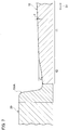
roadway boundary block 100 is further described.Fig. 3A is a side view of theroadway boundary block 100.Fig. 3B is a front view of theroadway boundary block 100. - As described above, the
roadway boundary block 100 is provided with thebase portion 110 and thecurbstone portion 150. As shown inFig. 3A and Fig. 3B , thebase portion 110 has aside surface 105 contacted with theroadway 10. Thecurbstone portion 150 has atop portion 170 located at the same level as thesidewalk 20. - As described above, the
side portion 160 is inclined to be far away from theroadway 10 in the direction from the lower end toward the upper end of thecurbstone portion 150. Specifically, theside portion 160 is inclined to be far away from an end portion of theroadway 10 in the road width direction. - An angle γ between the
side portion 160 and the vertical direction is preferably set to avoid excessive contact between the tire of thebus 50, in the present embodiment a side wall and a rim wheel of a tire forming the leftfront tire 51L (and the leftrear tire 52L), and aside portion 160, and to relax impact force when the leftfront tire 51L (and the leftrear tire 52L) is contacted with thecurbstone portion 150. For example, the angle γ is preferably set in a range between 5 degrees and 30 degrees. Here, the vertical direction is defined based on a state in which theroadway boundary block 100 is arranged between theroadway 10 and thesidewalk 20. - As shown in
Fig. 3A , in the present embodiment, theupper portion 120 is curved in a downward concave manner. A communication portion between theupper portion 120 and theside portion 160 is curved with a predetermined curvature. Specifically, the communication portion between theupper portion 120 and theside portion 160 is curved with a curvature radius R. For example, the curvature radius R is preferably set in a range between 75 mm and 150 mm. - The communication portion may not have a single curvature (curvature radius R) but have a plurality of curvatures. Further, the shape of the
upper portion 120 may also have a plurality of curvatures. Or alternatively, theupper portion 120 may be formed in a linear shape (namely a flat shape) without being curved. - Considering the tire side (tread width) of the tire to be mounted to the
bus 50, the width L of theupper portion 120 is preferably set to more than 300 mm. Here, the width L denotes a distance between theside surface 105 and the boundary position between theupper portion 120 and theside portion 160 along the upper portion 120 (surface). - In a case in which the boundary (communication portion) between the
upper portion 120 and theside portion 160 is curved, the boundary position is defined by an apex of the curved portion. - The
roadway boundary block 100 is generally formed of concrete similar to a normal curbstone, however considering the contact of theside portion 160 with the leftfront tire 51L or the like, theroadway boundary block 100 may be formed of rubber or reinforced plastic. - Next, functions and effects according to the road structure described above, namely the
roadway boundary block 100, are described. -
Fig. 4 to Fig. 6 are views (No. 1 to No. 3) for describing the functions according to theroadway boundary block 100. Specifically,Fig. 4 shows a state in which thebus 50 stops at thestop 30.Fig. 5 shows a state in which lateral force F is generated when the leftfront tire 51L is located on theroadway boundary block 100.Fig. 6 shows a change of a position of the leftfront tire 51L in accordance with travelling of thebus 50. - As shown in
Fig. 4 , when thebus 50 stops at thestop 30, thebus 50 approaches thestop 30 such that at least the leftfront tire 51L is located on theupper portion 120 of theroadway boundary block 100. As a result, in the timing when thebus 50 stops at thestop 30, a side portion of the leftfront tire 51L, namely a part of the side wall of the tire forming the leftfront tire 51L, is contacted with theside portion 160 of theroadway boundary block 100. - As described above, the
side portion 160 is inclined to be far away from theroadway 10 in the direction from the lower end toward the upper end, and therefore theside portion 160 is not contacted with a body of thebus 50 when a part of the side wall is contacted with theside portion 160 of theroadway boundary block 100. - Further, the left
rear tire 52L can be also located on theupper portion 120, however since the leftrear tire 52L is formed as a double tire, a part of a tire at an inner side (a side proximal to the center of the vehicle) may not be located on theupper portion 120. On the other hand, the rightfront tire 51R and the rightrear tire 52R are located on theroadway 10. - In the present embodiment, the approach of the
bus 50 to thestop 30 is facilitated by using theroadway boundary block 100 having the configuration described above. Specifically, as shown inFig. 5 , when the leftfront tire 51L is located on theupper portion 120, the lateral force F toward theside portion 160 is generated in the leftfront tire 51L. - More specifically, the lateral force F toward the
side portion 160 and lateral force F' (not shown) toward an opposite side, namely the lateral force F' toward a center side of theroadway 10, are generated in the leftfront tire 51L on theupper portion 120. - The lateral force F is generated based on a principle as below. Since the
upper portion 120 is inclined, compression force (CF1 in the figure) that compresses the rubber of the leftfront tire 51L (tire) at an inner side of the vehicle with respect to the leftfront tire 51L is larger than compression force (CF2 in the figure) that compresses the rubber of the rightfront tire 51L (tire) at an outer side of the vehicle with respect to the leftfront tire 51L. Generally, a rubber block having a rib shape due to acircumferential direction groove 51g extended in a tire circumferential direction is formed in the leftfront tire 51L (and other tires), and therefore the rubber block is deformed to be protruded in a tire width direction by the compression forces CF1 and CF2. The restoring force of the deformed rubber block to return to an original shape is based on each of the compression forces CF1 and CF2, and therefore the restoring force at the inner side of the vehicle is larger than the restoring force at the outer side of the vehicle. Thus, the lateral force F toward theside portion 160, namely the lateral force F downward along theupper portion 120, is generated by the restoring forces. - Further, the left
front tire 51L is generally provided with a plurality of belt layers (not shown) having high rigidity. The belt layer is formed by tire cords intersected with each other. Thus, when the rubber block, which is deformed between the belt layer and the ground contact surface, returns to the original shape, the lateral force F' (not shown) toward the center side of theroadway 10 is also generated. - However, since a size of a pneumatic radial tire for trucks or buses is larger than that of a pneumatic radial tire for passenger vehicles, the tread contacted with the road surface and the belt layer are separated in a pneumatic radial tire for trucks or buses, and therefore the lateral force F' is small. Accordingly, when the left
front tire 51L, which is a pneumatic tire for trucks or buses, is located on theupper portion 120, the lateral force F is generated and the leftfront tire 51L is pushed toward theside portion 160. - Further, as shown in
Fig. 6 , when the leftfront tire 51L is positioned at a position P1, the lateral force F described above is generated, and therefore the leftfront tire 51L is moved toward a position P2 while rolling. When the leftfront tire 51L is positioned at the position P2, further movement of the leftfront tire 51L toward thestop 30 is prevented by theside portion 160. - In this way, according to the present embodiment, the incline of the
upper portion 120 against the horizontal direction is larger than the incline of theroadway 10 against the horizontal direction in the road width direction (D1 direction, seeFig. 2 ). Further, the width L of theupper portion 120 along the road width direction is larger than the tire ground contact width (tread width) of thebus 50 and smaller than the tread (tread) of thebus 50. - Thus, the lateral force F as described above is generated, and therefore by driving the
bus 50 in a state in which the leftfront tire 51L (and the leftrear tire 52L) is located on theupper portion 120, thebus 50 can be automatically close to thestop 30. That is, a driver of thebus 50 may only hold a steering wheel with light force for making thebus 50 automatically close to thestop 30 without special operation to the steering wheel. Consequently, the precision docking to the getting on/offspot 31 and the getting on/offspot 32 is improved. - In a case of a conventional curbstone, the control of the
bus 50 to suppress impact when making the leftfront tire 51L or the like contact with the curbstone in order to minimize the distance between thedoorways 53 of thebus 50 and the getting on/offspot 31 and the getting on/offspot 32 is extremely difficult and has a high degree of difficulty. - Further, there are things to be focused on such as movement of passengers when approaching a stop, and therefore concentration of the driver might be deteriorated. However, according to the present embodiment, high driving ability is not necessary for improving the precision docking, and therefore the driver can focus on things other than the precision docking.
- Further, according to the present embodiment, a cost can be reduced and similar effects can be obtained compared to a method for improving the precision docking by means of automatic driving that recognizes a white line or the like on the
roadway 10 because it is only necessary to modify the curbstone, which is a part of the road structure, namely the roadway boundary block in the present embodiment. - As described above, it is preferable that the width L of the
upper portion 120 is set to more than 300 mm. In a case in which the width L is 300 mm or less, considering the size of the tire to be mounted to thebus 50, the whole ground contact width of the leftfront tire 51L might not be located on theupper portion 120, and therefore the lateral force F might not be generated sufficiently. - On the other hand, it is preferable that the width L of the
upper portion 120 is set to less than the tread of thebus 50. Actually, it is enough that the tire mounted to thebus 50 at a side of thesidewalk 20 is sufficiently located on theupper portion 120, and therefore the width L is set to up to a half of the tread of thebus 50. In a case in which the width L of theupper portion 120 is larger than the tread of thebus 50, both of the leftfront tire 51L and the rightfront tire 51R are located on the inclinedupper portion 120, and thereby the compression force CF1 at the inner side of the vehicle with respect to the leftfront tire 51L is made small. Such a configuration is not preferable because the lateral force F is not generated sufficiently. - Further, in the present embodiment, the
side portion 160 is inclined to be far away from theroadway 10 in the direction from the lower end toward the upper end of thecurbstone portion 150. Thus, the excessive contact between the side wall and the rim wheel of the tire forming the leftfront tire 51L (and the leftrear tire 52L), and theside portion 160 can be avoided, and the impact force when the leftfront tire 51L (and the leftrear tire 52L) is contacted with thecurbstone portion 150 can be relaxed. - As described above, although the content of the present invention was described through the embodiments, the present invention is not limited to those descriptions. It is obvious for a person skilled in the art that various modifications and improvements can be adopted.
-
Fig. 7 shows other embodiment of the road structure. Specifically,Fig. 7 corresponds toFig. 2 and is a cross-sectional view illustrating a part of theroadway 10 and thesidewalk 20 along the road width direction. The road structure shown inFig. 7 includes theroadway 10 on which a vehicle such as a bus 50 (not shown) travels, and acurbstone 150A arranged at a boundary of theroadway 10 to form a level difference against theroadway 10. - The
roadway 10 includes aroad portion 11 and aroad side portion 12. Theroad side portion 12 is arranged between theroadway 10, specifically theroad portion 11 forming theroadway 10, and thecurbstone 150A. - The
road side portion 12 corresponds to thebase portion 110 of theroadway boundary block 100 described above. Thecurbstone 150A is formed as a curbstone not having thebase portion 110, contrary to theroadway boundary block 100. - An incline of the
road side portion 12 against the horizontal direction is larger than an incline of theroadway 10 against the horizontal direction in the road width direction (D1 direction). A width of theroad side portion 12 along the road width direction is larger than the tire ground contact width of thebus 50 travelling on theroadway 10 and smaller than the tread of thebus 50. - Specifically, in the road width direction (D1 direction), an angle β between the
road side portion 12 and the horizontal direction is larger than an angle α between theroad portion 11 and the horizontal direction (β > α). - In this way, similar functions and effects to those of the
roadway boundary block 100 described above may be obtained by inclining theroad side portion 12 which is a part of theroadway 10. - The roadway boundary block 100 (see
Fig. 3A and Fig. 3B ) and thecurbstone 150A (seeFig. 7 ) described above may be modified in the following manner.Fig. 8A is a side view of aroadway boundary block 100A, andFig. 8B is a side view of acurbstone 150B. - As shown in
Fig. 8A , aside portion 160A of theroadway boundary block 100A is provided with afirst region 151 and asecond region 152. Thefirst region 151 is located to be close to anupper portion 120. Thesecond region 152 is located above thefirst region 151. - The
second region 152 is inclined more than thefirst region 151. That is, thesecond region 152 is further inclined to be far away from theroadway 10 in a direction from a lower end toward an upper end of thesecond region 152, compared to thefirst region 151. - In the present embodiment, each of the
first region 151 and thesecond region 152 of theside portion 160A is curved in a concave manner. Here, either one of thefirst region 151 and thesecond region 152, in particular thesecond region 152 not being contacted with a tire directly, may not be curved, and therefore thesecond region 152 may be formed in a linear shape (flat shape) inclined more than thefirst region 151. - Further, as shown in
Fig. 8B , thecurbstone 150B is provided with afirst region 151 and asecond region 152 having the same shape as theroadway boundary block 100A. - According to the
roadway boundary block 100A and thecurbstone 150B, since thesecond region 152 is further formed, contact with the body of thebus 50 can be avoided easily. In particular, an overhang portion of a front can be prevented from being contacted with the roadway boundary block or the curbstone when thebus 50 approaches thestop 30. - Further, the
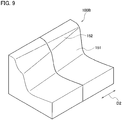
roadway boundary block 100A may be modified in the following manner.Fig. 9 is a schematic perspective view of aroadway boundary block 100B. - As shown in
Fig. 9 , asecond region 152 of theroadway boundary block 100B is inclined more than afirst region 151, similar to the configuration described above, and thesecond region 152 is reduced in an extension direction (D2 direction) along the roadway 10 (not shown) from one end toward another end of theroadway boundary block 100B. - Here, the
roadway boundary block 100B shown inFig. 9 is formed by two blocks and thesecond region 152 disappears at a side of another end, however a degree of reduction of thesecond region 152 may be different in accordance with a shape of theroadway 10, or an approach process of thebus 50 to the stop 30 (the approach while straight travelling or the approach while turning). - For example, in a case of the approach while turning (including a case in which the
bus 50 is shifted to be close to the stop 30 from a center side in the width direction of the roadway 10), an influence of an overhang portion of a front of thebus 50 is generally large, and therefore it is preferable to arrange thesecond region 152 to be long. Further, it is preferable that thesecond region 152 disappears at a side before the getting on/offspot 32 shown inFig. 1 in a travelling direction of thebus 50, from a viewpoint of improving the precision docking. It is because thesecond region 152 disappears at a position corresponding to thedoorway 53 of thebus 50 and thereby a distance (gap) between thecurbstone portion 150 and thedoorway 53 can be made further small. - Further, a curbstone having a shape similar to the
curbstone portion 150 of theroadway boundary block 100B described above may be adopted instead of thecurbstone 150B shown inFig. 8B . - The
roadway boundary block 100A (seeFig. 8A ) described above may be modified in the following manner.Fig. 10 is a side view of aroadway boundary block 100C. - As shown in
Fig. 10 , theroadway boundary block 100C is provided with afirst region 151A and asecond region 152A, similar to theroadway boundary block 100A. Thefirst region 151A has a shape similar to that of thefirst region 151 of theroadway boundary block 100A. Thefirst region 151A in inclined to be far away from theroadway 10 in a direction from a lower end toward an upper end of thefirst region 151A. - The
second region 152A has a shape different from that of thesecond region 152 of theroadway boundary block 100A. Specifically, thesecond region 152A is gouged in a height direction of theroadway boundary block 100C and a road width direction of theroadway 10, namely in a vertical direction and a horizontal direction. Specifically, thesecond region 152A is formed by avertical portion 153 extended in the vertical direction and ahorizontal portion 154 extended in the horizontal direction. - Further, the
roadway boundary block 100C may be modified in the following manner.Fig. 11 is a schematic perspective view of aroadway boundary block 100D. - As shown in
Fig. 11 , asecond region 152A of theroadway boundary block 100D is reduced in an extension direction (D2 direction) along the roadway 10 (not shown) from one end toward another end of theroadway boundary block 100D. - Here, the
roadway boundary block 100D shown inFig. 11 is formed by two blocks and thesecond region 152A disappears at a side of another end, similar to theroadway boundary block 100B (seeFig. 9 ), however a degree of reduction of thesecond region 152A may be different in accordance with a shape of theroadway 10, or an approach process of thebus 50 to the stop 30 (the approach while straight travelling or the approach while turning). - Further, a curbstone having a shape similar to the
curbstone portion 150 of any one of the roadway boundary blocks 100C and 100D described above may be adopted instead of thecurbstone 150B shown inFig. 8B . Further, thefirst region 151A of theroadway boundary block 100C may not be necessarily inclined to be far away from theroadway 10 in the direction from the lower end toward the upper end of thefirst region 151A. - In the embodiments described above, the
roadway 10 is described. Theroadway 10 includes not only a road for vehicles but also a vehicle passage in a bus terminal or the like. - As described above, although the embodiments of the present invention were described, the descriptions and drawings that form a part of this disclosure are not to be considered as limitation to the present invention. From this disclosure, a variety of alternate embodiments, examples, and applicable techniques will become apparent to one skilled in the art.
- The entire contents of Japanese Patent Application No.
2016-230298 (filed on November 28, 2016 - According to the roadway boundary block and the road structure according to the present invention, the precision docking to the stop can be easily improved without depending on high driving ability of a driver.
-
- 10: roadway
- 11: road portion
- 12: road side portion
- 20: sidewalk
- 30: stop
- 31: getting on/off spot
- 32: getting on/off spot
- 50: bus
- 51g: circumferential direction groove
- 51L: left front tire
- 51R: right front tire
- 52L: left rear tire
- 52R: right rear tire
- 53: doorway
- 100, 100A to 100D: roadway boundary block
- 105: side surface
- 110: base portion
- 120: upper portion
- 150: curbstone portion
- 150A, 150B: curbstone
- 151, 151A: first region
- 152, 152A: second region
- 153: vertical portion
- 154: horizontal portion
- 160, 160A: side portion
- 170: top portion
Claims (9)
- A roadway boundary block comprising:a base portion having an upper portion arranged to be continued to a roadway; anda curbstone portion raised from one end side of the base portion,wherein:an incline of the upper portion against a horizontal direction is larger than an incline of the roadway against the horizontal direction in a road width direction; anda width of the upper portion along the road width direction is larger than a tire ground contact width of a vehicle travelling on the roadway and smaller than a tread of the vehicle.
- The roadway boundary block according to claim 1, wherein a side portion of the curbstone portion at a side of the roadway is inclined to be far away from the roadway in a direction from a lower end toward an upper end of the curbstone portion.
- The roadway boundary block according to claim 2,
wherein:the side portion comprises a first region located to be close to the upper portion, and a second region located above the first region; andthe second region is inclined more than the first region. - The roadway boundary block according to claim 3, wherein either one of the first region and the second region is curved in a concave manner.
- The roadway boundary block according to claim 1,
wherein:a side portion of the curbstone portion at a side of the roadway comprises a first region located to be close to the upper portion, and a second region located above the first region; andthe second region is gouged in a vertical direction and a horizontal direction and is formed by a vertical portion extended in the vertical direction and a horizontal portion extended in the horizontal direction. - The roadway boundary block according to claim 5, wherein the first region is inclined to be far away from the roadway in a direction from a lower end toward an upper end of the first region.
- The roadway boundary block according to any one of claims 3 to 6, wherein the second region is reduced in an extension direction along the roadway from one end toward another end of the roadway boundary block.
- The roadway boundary block according to any one of claims 1 to 7, wherein the upper portion is curved in a downward concave manner.
- A road structure comprising:a roadway on which a vehicle travels; anda curbstone arranged at a boundary of the roadway to form a level difference against the roadway,wherein:a road side portion continued to the roadway is arranged between the roadway and the curbstone;an incline of the road side portion against a horizontal direction is larger an incline of the roadway against the horizontal direction in a road width direction; anda width of the road side portion along the road width direction is larger than a tire ground contact width of the vehicle travelling on the roadway and smaller than a tread of the vehicle.
Applications Claiming Priority (2)
| Application Number | Priority Date | Filing Date | Title |
|---|---|---|---|
| JP2016230298A JP6812218B2 (en) | 2016-11-28 | 2016-11-28 | Road boundary block and road structure |
| PCT/JP2017/035497 WO2018096788A1 (en) | 2016-11-28 | 2017-09-29 | Roadway boundary block and road structure |
Publications (3)
| Publication Number | Publication Date |
|---|---|
| EP3546651A1 true EP3546651A1 (en) | 2019-10-02 |
| EP3546651A4 EP3546651A4 (en) | 2020-10-07 |
| EP3546651B1 EP3546651B1 (en) | 2022-03-23 |
Family
ID=62196198
Family Applications (1)
| Application Number | Title | Priority Date | Filing Date |
|---|---|---|---|
| EP17874386.0A Active EP3546651B1 (en) | 2016-11-28 | 2017-09-29 | Roadway boundary block and road structure |
Country Status (5)
| Country | Link |
|---|---|
| US (1) | US20190376240A1 (en) |
| EP (1) | EP3546651B1 (en) |
| JP (1) | JP6812218B2 (en) |
| CN (1) | CN110023568A (en) |
| WO (1) | WO2018096788A1 (en) |
Families Citing this family (2)
| Publication number | Priority date | Publication date | Assignee | Title |
|---|---|---|---|---|
| JP7438069B2 (en) * | 2020-09-09 | 2024-02-26 | 株式会社ブリヂストン | remote distance measuring device |
| GB2604621B (en) * | 2021-03-10 | 2023-04-05 | Dromos Tech Ag | Platform wheel dent |
Family Cites Families (8)
| Publication number | Priority date | Publication date | Assignee | Title |
|---|---|---|---|---|
| BE565075A (en) * | ||||
| US775791A (en) * | 1904-07-23 | 1904-11-22 | Amos Austin | Curb, gutter, and drain block. |
| DE29810628U1 (en) * | 1998-06-17 | 1998-10-08 | Dresdner Verkehrsbetriebe AG, 01129 Dresden | Limitation of a carriageway for buses, especially at stops |
| JP2004332331A (en) * | 2003-05-06 | 2004-11-25 | Ito Yogyo Co Ltd | L-type culvert block and drainage structure of paved road using it |
| AU2010291874B2 (en) * | 2009-09-03 | 2015-02-19 | Vilenna Investments Pty Ltd | An arrangement and method for facilitating water usage |
| JP5534503B2 (en) * | 2009-10-23 | 2014-07-02 | 三谷セキサン株式会社 | L-shaped side groove block |
| DE202010005173U1 (en) | 2010-04-12 | 2011-08-30 | Profilbeton Gmbh | Curb and stop for bus transport |
| CN204825562U (en) * | 2015-08-18 | 2015-12-02 | 黑龙江省中信路桥材料有限公司 | Border structure of road |
-
2016
- 2016-11-28 JP JP2016230298A patent/JP6812218B2/en not_active Expired - Fee Related
-
2017
- 2017-09-29 US US16/463,513 patent/US20190376240A1/en not_active Abandoned
- 2017-09-29 WO PCT/JP2017/035497 patent/WO2018096788A1/en not_active Ceased
- 2017-09-29 EP EP17874386.0A patent/EP3546651B1/en active Active
- 2017-09-29 CN CN201780073616.3A patent/CN110023568A/en active Pending
Also Published As
| Publication number | Publication date |
|---|---|
| WO2018096788A1 (en) | 2018-05-31 |
| EP3546651B1 (en) | 2022-03-23 |
| US20190376240A1 (en) | 2019-12-12 |
| JP2018087420A (en) | 2018-06-07 |
| EP3546651A4 (en) | 2020-10-07 |
| JP6812218B2 (en) | 2021-01-13 |
| CN110023568A (en) | 2019-07-16 |
Similar Documents
| Publication | Publication Date | Title |
|---|---|---|
| JP5070171B2 (en) | Vehicle control device | |
| CN103180512B (en) | Branch device and rail transit system | |
| CN110956810B (en) | RSU and V2X-based complex road forward early warning method | |
| JP2002029216A (en) | Pneumatic tire and mounting method for it | |
| EP3546651B1 (en) | Roadway boundary block and road structure | |
| CN108437987A (en) | A kind of method and system preventing deviation | |
| JP5785010B2 (en) | tire | |
| BR112012026306B1 (en) | curb stone and stop for bus traffic | |
| JP2004358988A (en) | Vehicle with vehicle height adjustment function | |
| JP2001301425A (en) | Pneumatic tire | |
| CN112092562B (en) | Controlled pitch and tilt of the vehicle | |
| JP4634620B2 (en) | How to install a pneumatic tire | |
| CN1618635A (en) | Tread pattern structure of snow tires | |
| EP3603993A1 (en) | Tire | |
| CN219903947U (en) | Tire tread structure and tire with same | |
| WO2006038431A1 (en) | Front structure of vehicle | |
| AU2005254064A2 (en) | Portable speed bump | |
| GB2443546A (en) | Water spray reduction | |
| JP3993250B2 (en) | Pneumatic radial tire | |
| JP2021084591A (en) | tire | |
| KR102785932B1 (en) | Pneumatic tire | |
| JPS61139502A (en) | Pneumatic tyre | |
| EP1787885B1 (en) | Transport vehicle having wheels with tyres | |
| JP2004291775A (en) | Pneumatic tire | |
| JP3078900U (en) | Road shading plate |
Legal Events
| Date | Code | Title | Description |
|---|---|---|---|
| STAA | Information on the status of an ep patent application or granted ep patent |
Free format text: STATUS: THE INTERNATIONAL PUBLICATION HAS BEEN MADE |
|
| PUAI | Public reference made under article 153(3) epc to a published international application that has entered the european phase |
Free format text: ORIGINAL CODE: 0009012 |
|
| STAA | Information on the status of an ep patent application or granted ep patent |
Free format text: STATUS: REQUEST FOR EXAMINATION WAS MADE |
|
| 17P | Request for examination filed |
Effective date: 20190607 |
|
| AK | Designated contracting states |
Kind code of ref document: A1 Designated state(s): AL AT BE BG CH CY CZ DE DK EE ES FI FR GB GR HR HU IE IS IT LI LT LU LV MC MK MT NL NO PL PT RO RS SE SI SK SM TR |
|
| AX | Request for extension of the european patent |
Extension state: BA ME |
|
| DAV | Request for validation of the european patent (deleted) | ||
| DAX | Request for extension of the european patent (deleted) | ||
| A4 | Supplementary search report drawn up and despatched |
Effective date: 20200903 |
|
| RIC1 | Information provided on ipc code assigned before grant |
Ipc: E01C 11/22 20060101AFI20200828BHEP |
|
| GRAP | Despatch of communication of intention to grant a patent |
Free format text: ORIGINAL CODE: EPIDOSNIGR1 |
|
| STAA | Information on the status of an ep patent application or granted ep patent |
Free format text: STATUS: GRANT OF PATENT IS INTENDED |
|
| INTG | Intention to grant announced |
Effective date: 20211103 |
|
| GRAS | Grant fee paid |
Free format text: ORIGINAL CODE: EPIDOSNIGR3 |
|
| GRAA | (expected) grant |
Free format text: ORIGINAL CODE: 0009210 |
|
| STAA | Information on the status of an ep patent application or granted ep patent |
Free format text: STATUS: THE PATENT HAS BEEN GRANTED |
|
| AK | Designated contracting states |
Kind code of ref document: B1 Designated state(s): AL AT BE BG CH CY CZ DE DK EE ES FI FR GB GR HR HU IE IS IT LI LT LU LV MC MK MT NL NO PL PT RO RS SE SI SK SM TR |
|
| REG | Reference to a national code |
Ref country code: GB Ref legal event code: FG4D |
|
| REG | Reference to a national code |
Ref country code: CH Ref legal event code: EP |
|
| REG | Reference to a national code |
Ref country code: IE Ref legal event code: FG4D |
|
| REG | Reference to a national code |
Ref country code: DE Ref legal event code: R096 Ref document number: 602017055055 Country of ref document: DE |
|
| REG | Reference to a national code |
Ref country code: AT Ref legal event code: REF Ref document number: 1477506 Country of ref document: AT Kind code of ref document: T Effective date: 20220415 |
|
| REG | Reference to a national code |
Ref country code: LT Ref legal event code: MG9D |
|
| REG | Reference to a national code |
Ref country code: NL Ref legal event code: MP Effective date: 20220323 |
|
| PG25 | Lapsed in a contracting state [announced via postgrant information from national office to epo] |
Ref country code: SE Free format text: LAPSE BECAUSE OF FAILURE TO SUBMIT A TRANSLATION OF THE DESCRIPTION OR TO PAY THE FEE WITHIN THE PRESCRIBED TIME-LIMIT Effective date: 20220323 Ref country code: RS Free format text: LAPSE BECAUSE OF FAILURE TO SUBMIT A TRANSLATION OF THE DESCRIPTION OR TO PAY THE FEE WITHIN THE PRESCRIBED TIME-LIMIT Effective date: 20220323 Ref country code: NO Free format text: LAPSE BECAUSE OF FAILURE TO SUBMIT A TRANSLATION OF THE DESCRIPTION OR TO PAY THE FEE WITHIN THE PRESCRIBED TIME-LIMIT Effective date: 20220623 Ref country code: LT Free format text: LAPSE BECAUSE OF FAILURE TO SUBMIT A TRANSLATION OF THE DESCRIPTION OR TO PAY THE FEE WITHIN THE PRESCRIBED TIME-LIMIT Effective date: 20220323 Ref country code: HR Free format text: LAPSE BECAUSE OF FAILURE TO SUBMIT A TRANSLATION OF THE DESCRIPTION OR TO PAY THE FEE WITHIN THE PRESCRIBED TIME-LIMIT Effective date: 20220323 Ref country code: BG Free format text: LAPSE BECAUSE OF FAILURE TO SUBMIT A TRANSLATION OF THE DESCRIPTION OR TO PAY THE FEE WITHIN THE PRESCRIBED TIME-LIMIT Effective date: 20220623 |
|
| REG | Reference to a national code |
Ref country code: AT Ref legal event code: MK05 Ref document number: 1477506 Country of ref document: AT Kind code of ref document: T Effective date: 20220323 |
|
| PG25 | Lapsed in a contracting state [announced via postgrant information from national office to epo] |
Ref country code: LV Free format text: LAPSE BECAUSE OF FAILURE TO SUBMIT A TRANSLATION OF THE DESCRIPTION OR TO PAY THE FEE WITHIN THE PRESCRIBED TIME-LIMIT Effective date: 20220323 Ref country code: GR Free format text: LAPSE BECAUSE OF FAILURE TO SUBMIT A TRANSLATION OF THE DESCRIPTION OR TO PAY THE FEE WITHIN THE PRESCRIBED TIME-LIMIT Effective date: 20220624 Ref country code: FI Free format text: LAPSE BECAUSE OF FAILURE TO SUBMIT A TRANSLATION OF THE DESCRIPTION OR TO PAY THE FEE WITHIN THE PRESCRIBED TIME-LIMIT Effective date: 20220323 |
|
| PG25 | Lapsed in a contracting state [announced via postgrant information from national office to epo] |
Ref country code: NL Free format text: LAPSE BECAUSE OF FAILURE TO SUBMIT A TRANSLATION OF THE DESCRIPTION OR TO PAY THE FEE WITHIN THE PRESCRIBED TIME-LIMIT Effective date: 20220323 |
|
| PG25 | Lapsed in a contracting state [announced via postgrant information from national office to epo] |
Ref country code: SM Free format text: LAPSE BECAUSE OF FAILURE TO SUBMIT A TRANSLATION OF THE DESCRIPTION OR TO PAY THE FEE WITHIN THE PRESCRIBED TIME-LIMIT Effective date: 20220323 Ref country code: SK Free format text: LAPSE BECAUSE OF FAILURE TO SUBMIT A TRANSLATION OF THE DESCRIPTION OR TO PAY THE FEE WITHIN THE PRESCRIBED TIME-LIMIT Effective date: 20220323 Ref country code: RO Free format text: LAPSE BECAUSE OF FAILURE TO SUBMIT A TRANSLATION OF THE DESCRIPTION OR TO PAY THE FEE WITHIN THE PRESCRIBED TIME-LIMIT Effective date: 20220323 Ref country code: PT Free format text: LAPSE BECAUSE OF FAILURE TO SUBMIT A TRANSLATION OF THE DESCRIPTION OR TO PAY THE FEE WITHIN THE PRESCRIBED TIME-LIMIT Effective date: 20220725 Ref country code: ES Free format text: LAPSE BECAUSE OF FAILURE TO SUBMIT A TRANSLATION OF THE DESCRIPTION OR TO PAY THE FEE WITHIN THE PRESCRIBED TIME-LIMIT Effective date: 20220323 Ref country code: EE Free format text: LAPSE BECAUSE OF FAILURE TO SUBMIT A TRANSLATION OF THE DESCRIPTION OR TO PAY THE FEE WITHIN THE PRESCRIBED TIME-LIMIT Effective date: 20220323 Ref country code: CZ Free format text: LAPSE BECAUSE OF FAILURE TO SUBMIT A TRANSLATION OF THE DESCRIPTION OR TO PAY THE FEE WITHIN THE PRESCRIBED TIME-LIMIT Effective date: 20220323 Ref country code: AT Free format text: LAPSE BECAUSE OF FAILURE TO SUBMIT A TRANSLATION OF THE DESCRIPTION OR TO PAY THE FEE WITHIN THE PRESCRIBED TIME-LIMIT Effective date: 20220323 |
|
| PG25 | Lapsed in a contracting state [announced via postgrant information from national office to epo] |
Ref country code: PL Free format text: LAPSE BECAUSE OF FAILURE TO SUBMIT A TRANSLATION OF THE DESCRIPTION OR TO PAY THE FEE WITHIN THE PRESCRIBED TIME-LIMIT Effective date: 20220323 Ref country code: IS Free format text: LAPSE BECAUSE OF FAILURE TO SUBMIT A TRANSLATION OF THE DESCRIPTION OR TO PAY THE FEE WITHIN THE PRESCRIBED TIME-LIMIT Effective date: 20220723 Ref country code: AL Free format text: LAPSE BECAUSE OF FAILURE TO SUBMIT A TRANSLATION OF THE DESCRIPTION OR TO PAY THE FEE WITHIN THE PRESCRIBED TIME-LIMIT Effective date: 20220323 |
|
| REG | Reference to a national code |
Ref country code: DE Ref legal event code: R097 Ref document number: 602017055055 Country of ref document: DE |
|
| PLBE | No opposition filed within time limit |
Free format text: ORIGINAL CODE: 0009261 |
|
| STAA | Information on the status of an ep patent application or granted ep patent |
Free format text: STATUS: NO OPPOSITION FILED WITHIN TIME LIMIT |
|
| PG25 | Lapsed in a contracting state [announced via postgrant information from national office to epo] |
Ref country code: DK Free format text: LAPSE BECAUSE OF FAILURE TO SUBMIT A TRANSLATION OF THE DESCRIPTION OR TO PAY THE FEE WITHIN THE PRESCRIBED TIME-LIMIT Effective date: 20220323 |
|
| 26N | No opposition filed |
Effective date: 20230102 |
|
| PG25 | Lapsed in a contracting state [announced via postgrant information from national office to epo] |
Ref country code: MC Free format text: LAPSE BECAUSE OF FAILURE TO SUBMIT A TRANSLATION OF THE DESCRIPTION OR TO PAY THE FEE WITHIN THE PRESCRIBED TIME-LIMIT Effective date: 20220323 |
|
| REG | Reference to a national code |
Ref country code: CH Ref legal event code: PL |
|
| GBPC | Gb: european patent ceased through non-payment of renewal fee |
Effective date: 20220929 |
|
| REG | Reference to a national code |
Ref country code: BE Ref legal event code: MM Effective date: 20220930 |
|
| PG25 | Lapsed in a contracting state [announced via postgrant information from national office to epo] |
Ref country code: SI Free format text: LAPSE BECAUSE OF FAILURE TO SUBMIT A TRANSLATION OF THE DESCRIPTION OR TO PAY THE FEE WITHIN THE PRESCRIBED TIME-LIMIT Effective date: 20220323 |
|
| PG25 | Lapsed in a contracting state [announced via postgrant information from national office to epo] |
Ref country code: LU Free format text: LAPSE BECAUSE OF NON-PAYMENT OF DUE FEES Effective date: 20220929 |
|
| P01 | Opt-out of the competence of the unified patent court (upc) registered |
Effective date: 20230531 |
|
| PG25 | Lapsed in a contracting state [announced via postgrant information from national office to epo] |
Ref country code: LI Free format text: LAPSE BECAUSE OF NON-PAYMENT OF DUE FEES Effective date: 20220930 Ref country code: IT Free format text: LAPSE BECAUSE OF FAILURE TO SUBMIT A TRANSLATION OF THE DESCRIPTION OR TO PAY THE FEE WITHIN THE PRESCRIBED TIME-LIMIT Effective date: 20220323 Ref country code: IE Free format text: LAPSE BECAUSE OF NON-PAYMENT OF DUE FEES Effective date: 20220929 Ref country code: CH Free format text: LAPSE BECAUSE OF NON-PAYMENT OF DUE FEES Effective date: 20220930 |
|
| PG25 | Lapsed in a contracting state [announced via postgrant information from national office to epo] |
Ref country code: BE Free format text: LAPSE BECAUSE OF NON-PAYMENT OF DUE FEES Effective date: 20220930 |
|
| PG25 | Lapsed in a contracting state [announced via postgrant information from national office to epo] |
Ref country code: GB Free format text: LAPSE BECAUSE OF NON-PAYMENT OF DUE FEES Effective date: 20220929 |
|
| PG25 | Lapsed in a contracting state [announced via postgrant information from national office to epo] |
Ref country code: HU Free format text: LAPSE BECAUSE OF FAILURE TO SUBMIT A TRANSLATION OF THE DESCRIPTION OR TO PAY THE FEE WITHIN THE PRESCRIBED TIME-LIMIT; INVALID AB INITIO Effective date: 20170929 |
|
| PG25 | Lapsed in a contracting state [announced via postgrant information from national office to epo] |
Ref country code: CY Free format text: LAPSE BECAUSE OF FAILURE TO SUBMIT A TRANSLATION OF THE DESCRIPTION OR TO PAY THE FEE WITHIN THE PRESCRIBED TIME-LIMIT Effective date: 20220323 |
|
| PG25 | Lapsed in a contracting state [announced via postgrant information from national office to epo] |
Ref country code: MK Free format text: LAPSE BECAUSE OF FAILURE TO SUBMIT A TRANSLATION OF THE DESCRIPTION OR TO PAY THE FEE WITHIN THE PRESCRIBED TIME-LIMIT Effective date: 20220323 |
|
| PG25 | Lapsed in a contracting state [announced via postgrant information from national office to epo] |
Ref country code: MT Free format text: LAPSE BECAUSE OF FAILURE TO SUBMIT A TRANSLATION OF THE DESCRIPTION OR TO PAY THE FEE WITHIN THE PRESCRIBED TIME-LIMIT Effective date: 20220323 |
|
| PGFP | Annual fee paid to national office [announced via postgrant information from national office to epo] |
Ref country code: DE Payment date: 20250919 Year of fee payment: 9 |
|
| PGFP | Annual fee paid to national office [announced via postgrant information from national office to epo] |
Ref country code: FR Payment date: 20250922 Year of fee payment: 9 |
|
| PG25 | Lapsed in a contracting state [announced via postgrant information from national office to epo] |
Ref country code: TR Free format text: LAPSE BECAUSE OF FAILURE TO SUBMIT A TRANSLATION OF THE DESCRIPTION OR TO PAY THE FEE WITHIN THE PRESCRIBED TIME-LIMIT Effective date: 20220323 |