EP3546610A1 - As-rolled type electric-resistance-welded steel pipe for line pipes - Google Patents
As-rolled type electric-resistance-welded steel pipe for line pipes Download PDFInfo
- Publication number
- EP3546610A1 EP3546610A1 EP17904175.1A EP17904175A EP3546610A1 EP 3546610 A1 EP3546610 A1 EP 3546610A1 EP 17904175 A EP17904175 A EP 17904175A EP 3546610 A1 EP3546610 A1 EP 3546610A1
- Authority
- EP
- European Patent Office
- Prior art keywords
- less
- electric resistance
- base metal
- metal portion
- steel pipe
- Prior art date
- Legal status (The legal status is an assumption and is not a legal conclusion. Google has not performed a legal analysis and makes no representation as to the accuracy of the status listed.)
- Granted
Links
Images


Classifications
-
- C—CHEMISTRY; METALLURGY
- C22—METALLURGY; FERROUS OR NON-FERROUS ALLOYS; TREATMENT OF ALLOYS OR NON-FERROUS METALS
- C22C—ALLOYS
- C22C38/00—Ferrous alloys, e.g. steel alloys
- C22C38/001—Ferrous alloys, e.g. steel alloys containing N
-
- C—CHEMISTRY; METALLURGY
- C21—METALLURGY OF IRON
- C21D—MODIFYING THE PHYSICAL STRUCTURE OF FERROUS METALS; GENERAL DEVICES FOR HEAT TREATMENT OF FERROUS OR NON-FERROUS METALS OR ALLOYS; MAKING METAL MALLEABLE, e.g. BY DECARBURISATION OR TEMPERING
- C21D8/00—Modifying the physical properties of ferrous metals or ferrous alloys by deformation combined with, or followed by, heat treatment
- C21D8/10—Modifying the physical properties of ferrous metals or ferrous alloys by deformation combined with, or followed by, heat treatment during manufacturing of tubular bodies
-
- C—CHEMISTRY; METALLURGY
- C21—METALLURGY OF IRON
- C21D—MODIFYING THE PHYSICAL STRUCTURE OF FERROUS METALS; GENERAL DEVICES FOR HEAT TREATMENT OF FERROUS OR NON-FERROUS METALS OR ALLOYS; MAKING METAL MALLEABLE, e.g. BY DECARBURISATION OR TEMPERING
- C21D9/00—Heat treatment, e.g. annealing, hardening, quenching or tempering, adapted for particular articles; Furnaces therefor
- C21D9/08—Heat treatment, e.g. annealing, hardening, quenching or tempering, adapted for particular articles; Furnaces therefor for tubular bodies or pipes
-
- C—CHEMISTRY; METALLURGY
- C21—METALLURGY OF IRON
- C21D—MODIFYING THE PHYSICAL STRUCTURE OF FERROUS METALS; GENERAL DEVICES FOR HEAT TREATMENT OF FERROUS OR NON-FERROUS METALS OR ALLOYS; MAKING METAL MALLEABLE, e.g. BY DECARBURISATION OR TEMPERING
- C21D9/00—Heat treatment, e.g. annealing, hardening, quenching or tempering, adapted for particular articles; Furnaces therefor
- C21D9/50—Heat treatment, e.g. annealing, hardening, quenching or tempering, adapted for particular articles; Furnaces therefor for welded joints
-
- C—CHEMISTRY; METALLURGY
- C22—METALLURGY; FERROUS OR NON-FERROUS ALLOYS; TREATMENT OF ALLOYS OR NON-FERROUS METALS
- C22C—ALLOYS
- C22C38/00—Ferrous alloys, e.g. steel alloys
-
- C—CHEMISTRY; METALLURGY
- C22—METALLURGY; FERROUS OR NON-FERROUS ALLOYS; TREATMENT OF ALLOYS OR NON-FERROUS METALS
- C22C—ALLOYS
- C22C38/00—Ferrous alloys, e.g. steel alloys
- C22C38/04—Ferrous alloys, e.g. steel alloys containing manganese
-
- C—CHEMISTRY; METALLURGY
- C22—METALLURGY; FERROUS OR NON-FERROUS ALLOYS; TREATMENT OF ALLOYS OR NON-FERROUS METALS
- C22C—ALLOYS
- C22C38/00—Ferrous alloys, e.g. steel alloys
- C22C38/12—Ferrous alloys, e.g. steel alloys containing tungsten, tantalum, molybdenum, vanadium, or niobium
-
- C—CHEMISTRY; METALLURGY
- C22—METALLURGY; FERROUS OR NON-FERROUS ALLOYS; TREATMENT OF ALLOYS OR NON-FERROUS METALS
- C22C—ALLOYS
- C22C38/00—Ferrous alloys, e.g. steel alloys
- C22C38/14—Ferrous alloys, e.g. steel alloys containing titanium or zirconium
-
- C—CHEMISTRY; METALLURGY
- C22—METALLURGY; FERROUS OR NON-FERROUS ALLOYS; TREATMENT OF ALLOYS OR NON-FERROUS METALS
- C22C—ALLOYS
- C22C38/00—Ferrous alloys, e.g. steel alloys
- C22C38/18—Ferrous alloys, e.g. steel alloys containing chromium
- C22C38/40—Ferrous alloys, e.g. steel alloys containing chromium with nickel
- C22C38/58—Ferrous alloys, e.g. steel alloys containing chromium with nickel with more than 1.5% by weight of manganese
-
- C—CHEMISTRY; METALLURGY
- C21—METALLURGY OF IRON
- C21D—MODIFYING THE PHYSICAL STRUCTURE OF FERROUS METALS; GENERAL DEVICES FOR HEAT TREATMENT OF FERROUS OR NON-FERROUS METALS OR ALLOYS; MAKING METAL MALLEABLE, e.g. BY DECARBURISATION OR TEMPERING
- C21D2211/00—Microstructure comprising significant phases
- C21D2211/005—Ferrite
Definitions
- the present disclosure relates to an as-rolled electric resistance welded steel pipe for a line pipe.
- Crude oil or natural gas produced in recent years includes wet hydrogen sulfide (H 2 S).
- An environment including hydrogen sulfide is referred to as a sour environment.
- a pipeline for transporting drilled crude oil or natural gas is exposed to such a sour environment.
- sour resistance resistance to a sour environment
- Patent Document 1 discloses, as a thick-walled high-strength hot-rolled steel sheet for a line pipe, which has excellent sour resistance, a thick-walled high-strength hot-rolled steel sheet for a line pipe, which has a composition including, in terms of % by mass, from 0.01 to 0.07% of C, 0.40% or less of Si, from 0.5 to 1.4% of Mn, 0.015% or less of P, 0.003% or less of S, 0.1% or less of Al, from 0.01 to 0.15% of Nb, 0.1% or less of V, 0.03% or less of Ti, and 0.008% or less of N, such that Nb, V, and Ti satisfy Nb + V + Ti ⁇ 0.15, and further Cm satisfies 0.12 or less, and the balance of the composition consists of Fe and inevitable impurities, and has a structure including a bainite phase or a bain
- Patent Document 1 JP-A No. 2013-11005
- sour resistance includes resistance to hydrogen induced cracking (hereinafter also referred to as “HIC”) generated mainly in the central portion of the wall thickness of the steel pipe (hereinafter also referred to as “HIC resistance”) and resistance to sulfide stress cracking (hereinafter also referred to as "SSC”) generated mainly from the inner peripheral surface of the steel pipe as the initiating point (hereinafter also referred to as "SSC resistance”).
- HIC hydrogen induced cracking
- SSC sulfide stress cracking
- Patent Document 1 only the HIC resistance is evaluated, and the SSC resistance is not evaluated as the sour resistance.
- the high-strength hot-rolled steel sheet for a welded steel pipe for a line pipe of Patent Document 1 may have low SSC resistance.
- a certain amount of high strength for example, a yield strength in a pipe axis direction of 415 MPa or more, and a tensile strength in the pipe axis direction of 461 MPa or more) is required.
- not-too-high strength for example, the yield strength in the pipe axis direction of 550 MPa or less, and the tensile strength in the pipe axis direction of 625 MPa or less.
- an object of the disclosure is to provide an as-rolled electric resistance welded steel pipe for a line pipe, which has a yield strength in a pipe axis direction of from 415 to 550 MPa, which has a tensile strength in the pipe axis direction of from 461 to 625 MPa, and which has excellent SSC resistance.
- Means of solving the problem described above includes the following aspects.
- an as-rolled electric resistance welded steel pipe for a line pipe which has a yield strength in a pipe axis direction of from 415 to 550 MPa, which has a tensile strength in the pipe axis direction of from 461 to 625 MPa, and which has excellent SSC resistance, is provided.
- a numerical range expressed by "from x to y" herein includes the values of x and y in the range as the minimum and maximum values, respectively.
- the content of a component (element) expressed by “%” herein means “% by mass”.
- the content of C (carbon) in a base metal portion may be herein occasionally expressed as "C content”.
- the content of another element in the base metal portion may be expressed similarly.
- step herein encompasses not only an independent step but also a step of which the desired object is achieved even in a case in which the step is incapable of being definitely distinguished from another step.
- an "as-rolled electric resistance welded steel pipe for a line pipe” may be simply referred to as an “electric resistance welded steel pipe” or an “as-rolled electric resistance welded steel pipe”.
- the as-rolled electric resistance welded steel pipe refers to an electric resistance welded steel pipe which is not subjected to heat treatment other than seam heat treatment after pipe-making.
- the "pipe-making” refers to a process of making an open pipe by roll-forming of a hot-rolled steel sheet and forming an electric resistance welded portion by electric resistance welding of abutting portions of the obtained open pipe.
- roll-forming refers to forming of a hot-rolled steel sheet into an open pipe shape by bending work.
- An electric resistance welded steel pipe (i.e., an as-rolled electric resistance welded steel pipe for a line pipe) of the disclosure includes a base metal portion and an electric resistance welded portion, wherein a chemical composition of the base metal portion consists of, in terms of% by mass: from 0.01 to 0.10% of C, from 0.01 to 0.40% of Si, from 0.50 to 2.00% of Mn, from 0 to 0.030% of P, from 0 to 0.0015% of S, from 0.010 to 0.050% of Al, from 0.0030 to 0.0080% of N, from 0.010 to 0.050% of Nb, from 0.005 to 0.020% of Ti, from 0 to 0.20% of Ni, from 0 to 0.20% of Mo, from 0 to 0.0050% of Ca, from 0 to 1.00% of Cr, from 0 to 0.100% of V, from 0 to 1.00% of Cu, from 0 to 0.0050% of Mg, from 0 to 0.0100% of REM, and the balance being Fe
- the base metal portion refers to a portion other than the electric resistance welded portion and a heat affected zone in the electric resistance welded steel pipe.
- the heat affected zone (hereinafter also referred to as "HAZ”) refers to a portion affected by heat caused by electric resistance welding (affected by heat caused by the electric resistance welding and seam heat treatment in a case in which the seam heat treatment is performed after the electric resistance welding).
- the maximum Vickers hardness of the inner surface layer of the base metal portion means a value measured as follows.
- the maximum value among the obtained nine measurement results is regarded as the maximum Vickers hardness of the inner surface layer of the base metal portion.
- the maximum Vickers hardness of the inner surface layer of the base metal portion is, approximately speaking, a maximum Vickers hardness in the vicinity of the inner peripheral surface of the base metal portion.
- the maximum Vickers hardness of the outer surface layer of the base metal portion means a value measured in the same way as the maximum Vickers hardness of the inner surface of the base metal portion described above except that the "inner peripheral surface” is read as the "outer peripheral surface”.
- the maximum Vickers hardness of the outer surface layer of the base metal portion is, approximately speaking, a maximum Vickers hardness in the vicinity of the outer peripheral surface of the base metal portion.
- the electric resistance welded steel pipe of the disclosure has a certain amount of strength (i.e., YS and TS in the ranges described above) and has excellent SSC resistance.
- HIC hydrogen induced cracking
- SSC sulfuride stress cracking
- the electric resistance welded steel pipe may have poor SSC resistance.
- the maximum Vickers hardness of the inner surface layer of the base metal portion is 248 HV or less, and the maximum Vickers hardness of the inner surface layer of the base metal portion is smaller than the maximum Vickers hardness of the outer surface layer of the base metal portion by 5 HV or more.
- SSC tends to be easily generated as the strength of the electric resistance welded steel pipe becomes higher.
- the YS is limited to 550 MPa or less, and the TS is limited to 625 MPa or less, respectively. As a result, the SSC resistance is improved.
- the maximum Vickers hardness of the inner surface layer of the base metal portion is smaller than the maximum Vickers hardness of the outer surface layer of the base metal portion by 5 HV or more, so that the maximum Vickers hardness of the outer surface layer of the base metal portion is relatively secured to a certain degree.
- a certain amount of high strength (specifically, YS of 415 MPa or more, and TS of 461 MPa or more) is secured as the entire electric resistance welded steel pipe.
- the maximum Vickers hardness of the inner surface layer of the base metal portion was almost the same as the maximum Vickers hardness of the outer surface layer of the base metal portion, and the condition that "the maximum Vickers hardness of the inner surface layer of the base metal portion is smaller than the maximum Vickers hardness of the outer surface layer of the base metal portion by 5 HV or more" was not satisfied owing to the following circumstances.
- the electric resistance welded steel pipe is produced by using a hot coil consisting of a hot-rolled steel sheet as a raw material and subjecting the hot-rolled steel sheet, uncoiled from the hot coil, to pipe-making (i.e., roll-forming and electric resistance welding).
- a hot coil consisting of a hot-rolled steel sheet as a raw material and subjecting the hot-rolled steel sheet, uncoiled from the hot coil, to pipe-making (i.e., roll-forming and electric resistance welding).
- first surface One of two surfaces of the hot-rolled steel sheet uncoiled from the hot coil
- second surface becomes an inner surface of the electric resistance welded steel pipe.
- a production process of the hot coil includes respective stages of hot-rolling, cooling, and coiling in this order.
- this cooling was conventionally performed by water-cooling the two surfaces of the hot-rolled steel sheet obtained by hot-rolling at cooling rates which are almost the same.
- the maximum Vickers hardness of the inner surface layer of the base metal portion was almost the same as the maximum Vickers hardness of the outer surface layer of the base metal portion (i.e., the condition that "the maximum Vickers hardness of the inner surface layer of the base metal portion is smaller than the maximum Vickers hardness of the outer surface layer of the base metal portion by 5 HV or more" was not satisfied).
- the present inventors succeeded in making the maximum Vickers hardness of the inner surface layer of the base metal portion smaller than the maximum Vickers hardness of the outer surface layer of the base metal portion by 5 HV or more by providing a difference between the cooling rates for the two surfaces when the two surfaces of the hot-rolled steel sheet obtained by hot-rolling are cooled (specifically, by making the cooling rate of the second surface corresponding to the inner peripheral surface slower than the cooling rate of the first surface corresponding to the outer peripheral surface). Furthermore, the present inventors found that, virtually, the warpage of the hot-rolled steel sheet after cooling is not matter too much because the cooled hot-rolled steel sheet is subsequently coiled.
- the chemical composition of the base metal portion, the metallographic microstructure of the base metal portion, and being the as-rolled electric resistance welded steel pipe also contribute to the achievement of the YS in the range described above and the TS in the range described above.
- the C content is 0.01% or more.
- the C content is preferably 0.03% or more, and more preferably 0.04% or more.
- the C content is 0.10% or less.
- the C content is preferably 0.09%, and still more preferably 0.08% or less.
- Si from 0.01 to 0.40%
- the Si deoxidizes steel. In a case in which a Si content is too low, the effect cannot be obtained. Accordingly, the Si content is 0.01% or more.
- the Si content is preferably 0.02% or more, and still more preferably 0.10% or more.
- the Si content is 0.40% or less.
- the Si content is preferably 0.38% or less, and more preferably 0.35% or less.
- Mn from 0.50 to 2.00%
- Mn enhances the hardenability of steel and enhances the strength of steel. In a case in which a Mn content is too low, the effect cannot be obtained. Accordingly, the Mn content is 0.50% or more.
- the Mn content is preferably 0.60% or more, and more preferably 0.80% or more.
- the Mn content is 2.00% or less.
- the Mn content is preferably 1.80% or less, and more preferably 1.50% or less.
- a P content is preferably small. Specifically, the P content is 0.030% or less. The P content is preferably 0.021% or less, more preferably 0.015% or less, and still more preferably 0.010% or less.
- the P content may be 0%. From the viewpoint of reducing a dephosphorization cost, the P content may be more than 0%, and may be 0.001% or more.
- S is an impurity.
- S binds to Mn to form a Mn-based sulfide.
- the Mn-based sulfide is diffluent.
- the toughness and SSC resistance of steel are decreased.
- a S content is preferably as low as possible. Specifically, the S content is 0.0015% or less.
- the S content is preferably 0.0010% or less, and more preferably 0.0008% or less.
- the S content may be 0%.
- the S content may be more than 0%, may be 0.0001% or more, and may be 0.0003% or more.
- Al deoxidizes steel. In a case in which an Al content is too low, the effect cannot be obtained. Accordingly, the Al content is 0.010% or more.
- the Al content is preferably 0.012% or more, and more preferably 0.013% or more.
- the Al content is 0.050% or less.
- the Al content is preferably 0.040% or less, more preferably 0.035% or less, and still more preferably 0.030% or less.
- the Al content herein means the content of total Al in the steel.
- N enhances the strength of steel by solid-solution strengthening. In a case in which a N content is too low, the effect cannot be obtained. Accordingly, the N content is 0.0030% or more.
- the N content is 0.0080% or less.
- the N content is preferably 0.0070% or less, more preferably 0.0060% or less, and still more preferably 0.0040% or less.
- Nb from 0.010 to 0.050%
- Nb binds to C and N in the steel to form a fine Nb carbonitride.
- the fine Nb carbonitride enhances the strength of steel by dispersion strengthening. In a case in which a Nb content is too low, the effect cannot be obtained. Accordingly, the Nb content is 0.010% or more.
- the Nb content is preferably 0.020% or more, and more preferably 0.030% or more.
- the Nb content is 0.050% or less.
- the Nb content is preferably 0.045% or less, and more preferably 0.040% or less.
- Ti binds to N in the steel to form a Ti nitride and/or Ti carbonitride.
- the Ti nitride and/or Ti carbonitride refines crystal grains of the steel. In a case in which a Ti content is too low, the effect cannot be obtained. Accordingly, the Ti content is 0.005% or more.
- the Ti content is preferably 0.007% or more, and more preferably 0.010% or more.
- the Ti content is 0.020% or less.
- the Ti content is preferably 0.018% or less, and more preferably 0.016% or less.
- Ni from 0 to 0.20%
- Ni is an optional element and may not be contained. In other words, a Ni content may be 0%.
- Ni enhances the strength of steel by solid-solution strengthening. Ni further enhances the toughness of steel. From the viewpoint of the effect, the Ni content is preferably more than 0%, more preferably 0.001% or more, more preferably 0.005% or more, still more preferably 0.01% or more, and still more preferably 0.05% or more.
- the Ni content is 0.20% or less.
- the Ni content is preferably 0.18% or less, and still more preferably 0.15% or less.
- Mo is an optional element and may not be contained. In other words, a Mo content may be 0%.
- Mo In a case in which Mo is contained, Mo enhances the hardenability of steel and enhances the strength of steel. Furthermore, since micro segregation of Mo is difficult to be generated, generation of HIC caused by center segregation is suppressed. From the viewpoint of the effect, the Mo content is preferably more than 0%, more preferably 0.10% or more, and still more preferably 0.12% or more.
- the Mo content is 0.20% or less.
- the Mo content is preferably 0.18% or less, and more preferably 0.15% or less.
- Ca is an optional element and may not be contained. In other words, a Ca content may be 0%.
- Ca makes the form of MnS that becomes a initiating point of generation of SSC into a spherical shape and suppresses the generation of SSC.
- Ca further forms CaS and suppresses generation of MnS.
- the Ca content is preferably more than 0%, more preferably 0.0005% or more, still more preferably 0.0010% or more, and still more preferably 0.0020% or more.
- the Ca content is 0.0050% or less.
- the Ca content is preferably 0.0045% or less.
- Cr is an optional element and may not be contained. In other words, a Cr content may be 0%.
- the Cr content is preferably more than 0%, and more preferably 0.01% or more.
- the Cr content is 1.00% or less.
- the Cr content is preferably 0.50% or less, more preferably 0.30% or less, and still more preferably 0.20% or less.
- V from 0 to 0.100%
- V is an optional element and may not be contained. In other words, a V content may be 0%.
- V contributes to improvement in toughness.
- the V content is preferably more than 0%, more preferably 0.001% or more, and still more preferably 0.005% or more.
- the V content is 0.100% or less.
- the V content is preferably 0.070% or less, more preferably 0.050% or less, and still more preferably 0.030% or less.
- Cu is an optional element and may not be contained. In other words, a Cu content may be 0%.
- Cu contributes to improvement in the strength of the base metal portion.
- the Cu content is preferably more than 0%, more preferably 0.01% or more, and still more preferably 0.05% or more.
- the Cu content is 1.00% or less.
- the Cu content is preferably 0.70% or less, more preferably 0.50% or less, and still more preferably 0.30% or less.
- Mg is an optional element and may not be contained. In other words, a Mg content may be 0%.
- Mg functions as a deoxidizer and a desulfurizer. Moreover, Mg forms a fine oxide and also contributes to improvement in the toughness of an HAZ. From the viewpoint of the effect, the Mg content is preferably more than 0%, more preferably 0.0001% or more, and still more preferably 0.0010% or more.
- the Mg content is 0.0050% or less.
- the Mg content is preferably 0.0030% or less.
- REM is an optional element and may not be contained. In other words, an REM content may be 0%.
- REM refers to a rare earth element, i.e., at least one element selected from the group consisting of Sc, Y, La, Ce, Pr, Nd, Pm, Sm, Eu, Gd, Tb, Dy, Ho, Er, Tm, Yb, and Lu.
- REM functions as a deoxidizer and a desulfurizer.
- the REM content is preferably more than 0%, more preferably 0.0001% or more, and still more preferably 0.0010% or more.
- the REM content is 0.0100% or less.
- the REM content is preferably 0.0070% or less, and more preferably 0.0050% or less.
- the chemical composition of the base metal portion may contain one or more selected from the group consisting of: more than 0% but equal to or less than 0.20% of Ni, more than 0% but equal to or less than 0.20% of Mo, more than 0% but equal to or less than 0.0050% of Ca, more than 0% but equal to or less than 1.00% of Cr, more than 0% but equal to or less than 0.100% of V, more than 0% but equal to or less than 1.00% of Cu, more than 0% but equal to or less than 0.0050% of Mg, and more than 0% but equal to or less than 0.0100% of REM.
- the balance excluding each element described above is Fe and impurities.
- the impurities refer to components which are contained in a raw material (for example, ore, scrap, and the like) or mixed into in a production step, and which are not intentionally incorporated into a steel.
- impurities examples include any elements other than the elements described above. Elements as the impurities may be only one kind, or may be two or more kinds.
- impurities examples include O, B, Sb, Sn, W, Co, As, Pb, Bi, and H.
- O is preferably controlled to have a content of 0.006% or less.
- Sb, Sn, W, Co, or As may be included in a content of 0.1 % or less
- Pb or Bi may be included in a content of 0.005% or less
- B may be included in a content of 0.0003% or less
- H may be included in a content of 0.0004% or less
- the contents of the other elements need not particularly be controlled as long as being in a usual range.
- an areal ratio of polygonal ferrite (hereinafter also referred to as "ferrite fraction") is from 80 to 98%, and the balance is composed of at least one of bainite or pearlite.
- a YS of 550 MPa or less and a TS of 625 MPa or less can be achieved by allowing a ferrite fraction to be 80% or more.
- the ferrite fraction is preferably 81% or more, and more preferably 82% or more.
- a YS of 415 MPa or more and a TS of 461 MPa or more can be achieved by allowing a ferrite fraction to be 98% or less.
- the ferrite fraction is preferably 97% or less, and more preferably 95% or less.
- the balance in the metallographic microstructure of the base metal portion is composed of at least one of bainite or pearlite.
- the SSC resistance is improved compared to a case in which the balance contains, for example, martensite.
- pearlite herein includes pseudo-pearlite.
- the above-described metallographic microstructure of the base metal portion relates to the electric resistance welded steel pipe of the disclosure being an as-rolled electric resistance welded steel pipe (i.e., not subjected to heat treatment other than seam heat treatment after pipe-making).
- martensite may be formed as the metallographic microstructure of the base metal portion.
- the electric resistance welded steel pipe in this case has poor SSC resistance.
- the measurement of the ferrite fraction and the identification of the balance in the metallographic microstructure of the base metal portion are performed as follows.
- a metallographic microstructure of the central portion of the wall thickness in an L cross-section at a base metal 180° position is nital-etched, and micrographs of the nital-etched metallographic microstructure (hereinafter also referred to as "metallographic micrographs") are observed with a scanning electron microscope (SEM) at a magnification of 500 times.
- SEM scanning electron microscope
- Metallographic micrographs corresponding to ten 500-times visual fields (corresponding to actual cross-sectional area of 0.48 mm 2 ) are taken.
- the measurement of the ferrite fraction and the identification of the balance are performed by performing image processing of the metallographic micrographs that were taken.
- the image processing is performed using, for example, a small-sized general-purpose image analysis apparatus LUZEX AP manufactured by NIRECO CORPORATION.
- Fig. 1 is a scanning electron micrograph (SEM micrograph; a magnification of 500 times) showing an example of a metallographic microstructure of a base metal portion in the disclosure
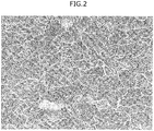
- Fig. 2 is a SEM micrograph (a magnification of 2,000 times) obtained by enlarging a region of Fig. 1 .
- the SEM micrograph (500 times) in Fig. 1 is one (one visual field) of SEM micrographs used in the measurement of the ferrite fraction and the identification of the balance in Test Number 22 described later.
- the metallographic microstructure according to this example is a metallographic microstructure which is mainly composed of polygonal ferrite and in which the balance is pearlite.
- the metallographic microstructure is revealed to be a metallographic microstructure which is not subjected to heat treatment after pipe-making (i.e., a metallographic microstructure of an as-rolled electric resistance welded steel pipe).
- a maximum Vickers hardness of an inner surface layer of the base metal portion is 248 HV or less, and the Vickers hardness of the inner surface layer of the base metal portion is smaller than a maximum Vickers hardness of an outer surface layer of the base metal portion by 5 HV or more.
- a difference obtained by subtracting the Vickers hardness of the inner surface layer of the base metal portion from the maximum Vickers hardness of the outer surface layer of the base metal portion is hereinafter also referred to as an "outer-inner hardness difference".
- the Vickers hardness of the inner surface layer of the base metal portion is smaller than the maximum Vickers hardness of the outer surface layer of the base metal portion by 5 HV or more
- the outer-inner hardness difference is 5 HV or more
- the maximum Vickers hardness of the inner surface layer of the base metal portion exceeds 248 HV, the toughness of steel is decreased, and the SSC resistance of the electric resistance welded steel pipe is decreased. Accordingly, the maximum Vickers hardness of the inner surface layer is 248 HV or less.
- the maximum Vickers hardness of the inner surface layer is preferably 245 HV or less, and more preferably 220 HV or less.
- the lower limit of the maximum Vickers hardness of the inner surface layer is not particularly limited. From the viewpoint of more improving the strength of the electric resistance welded steel pipe (i.e., YS and TS), the maximum Vickers hardness of the inner surface layer is preferably 175 HV or more, more preferably 180 HV or more, and still more preferably 185 HV or more.
- the outer-inner hardness difference is less than 5 HV, depending on the value of the maximum Vickers hardness of the inner surface layer of the base metal portion, at least one of the deterioration of the SSC resistance, the deficiency of the YS, or the deficiency of the TS occurs. Accordingly, the outer-inner hardness difference is 5 HV or more, and preferably 6 HV or more.
- the upper limit of the outer-inner hardness difference is not particularly restricted. From the viewpoint of the production suitability of the electric resistance welded steel pipe, the outer-inner hardness difference is preferably 20 HV or less, more preferably 15 HV or less, and still more preferably 10 HV or less.
- the maximum Vickers hardness of the outer surface layer of the base metal portion may satisfy the maximum Vickers hardness of the inner surface layer of the base metal portion and the outer-inner hardness difference described above, and others are not particularly restricted.
- the maximum Vickers hardness of the outer surface layer of the base metal portion is preferably from 180 MPa to 250 MPa, and more preferably from 210 MPa to 230 MPa.
- the Vickers hardness of the inner surface layer of the base metal portion is smaller than the maximum Vickers hardness of the outer surface layer of the base metal portion by 5 HV or more.
- the maximum Vickers hardness of the inner surface layer may be lower than the maximum Vickers hardness of the outer surface layer by 5 HV or more in not only the base metal portion but also the electric resistance welded portion.
- the maximum Vickers hardness of the inner surface layer may be lower than the maximum Vickers hardness of the outer surface layer by 5 HV or more also in the electric resistance welded portion.
- the electric resistance welded steel pipe of the disclosure has a yield strength in a pipe axis direction (YS) of from 415 to 550 MPa.
- a YS of 415 MPa or more secures the strength as the electric resistance welded steel pipe for a line pipe.
- the YS is preferably 430 MPa or more.
- a YS of 550 MPa or less is advantageous in view of the improvement in the SSC resistance or a bending deformation property and the suppression of buckling in the case of laying a pipeline formed using the electric resistance welded steel pipe for a line pipe.
- the YS is preferably 530 MPa or less.
- the electric resistance welded steel pipe of the disclosure has a tensile strength in a pipe axis direction (TS) of from 461 to 625 MPa.
- a TS of 461 MPa or more secures the strength as the electric resistance welded steel pipe for a line pipe.
- the TS is preferably 500 MPa or more, and more preferably 510 MPa or more.
- a TS of 625 MPa or less is advantageous in view of the improvement in the SSC resistance or a bending deformation property and the suppression of buckling in the case of laying a pipeline formed using the electric resistance welded steel pipe for a line pipe.
- the TS is preferably 620 MPa or less.
- the YS and the TS are measured by the following method.
- a full thickness tensile test specimen is sampled from the base metal 90° position of the electric resistance welded steel pipe. Specifically, the tensile test specimen is sampled such that a longitudinal direction of the tensile test specimen is parallel to the pipe axis direction of the electric resistance welded steel pipe and the shape of a cross-section of the tensile test specimen (i.e., a cross-section parallel to a width direction and a thickness direction of the tensile test specimen) is an arcuate shape.
- Fig. 3 is a schematic front view of a tensile test specimen used for a tensile test.
- a unit of numerical values in Fig. 3 is mm.
- the length of a parallel part of the tensile test specimen is set to be 50.8 mm, and the width of the parallel part is set to be 38.1 mm.
- the tensile test is conducted using the tensile test specimen in conformity with standard API, specification 5CT at ordinary temperature.
- the YS and the TS are determined based on the test result.
- a YR of 95% or less is advantageous in view of the suppression of buckling in the case of laying a pipeline formed using the electric resistance welded steel pipe for a line pipe.
- the wall thickness of the electric resistance welded steel pipe of the disclosure is preferably from 10 to 25 mm.
- the wall thickness is more preferably 12 mm or more.
- a wall thickness of 25 mm or less is advantageous in view of the production suitability of the electric resistance welded steel pipe (specifically, formability in formation of a hot-rolled steel sheet into a pipe shape).
- the wall thickness is more preferably 20 mm or less.
- the outer diameter of the electric resistance welded steel pipe of the disclosure is preferably from 114.3 to 660.4 mm (i.e., 4.5 to 26 inches).
- the outer diameter is preferably 152.4 mm (i.e., 6 inches) or more, and more preferably 254 mm (i.e., 10 inches) or more.
- the outer diameter is preferably 609.6 mm (i.e., 24 inches) or less, and more preferably 508 mm (i.e., 20 inches) or less.
- One example of a method of producing the electric resistance welded steel pipe of the disclosure is the following production method A.
- the production method A includes:
- the electric resistance welded steel pipe in which the hardness of the inner peripheral surface is lower than the hardness of the outer peripheral surface is easily produced, and therefore, the electric resistance welded steel pipe of the disclosure having an outer-inner hardness difference of 5 HV or more is easily produced.
- the step of preparing a slab is a step of preparing a slab having the chemical composition described above.
- the step of preparing a slab may be a step of producing a slab or a step of simply preparing a slab produced in advance.
- molten steel having the chemical composition described above is produced, and a slab is produced using the produced molten steel.
- the slab may be produced by continuous casting, or the slab may be produced by producing an ingot using molten steel and breaking down the ingot.
- the hot-rolling step is a step of heating the prepared slab described above and hot-rolling the heated slab, thereby obtaining a hot-rolled steel sheet.
- the heating temperature in heating the slab is preferably from 1,100 to 1,250°C.
- the heating temperature is 1,100°C or more
- refining of crystal grains during hot-rolling and precipitation strengthening after hot-rolling easily proceed, and therefore, the strength of steel is easily improved.
- the heating temperature is 1,250°C or less, since coarsening of austenite grains can be more suppressed, crystal grains are easily refined, and therefore, the strength of steel is easily improved.
- the heating of the slab is performed by, for example, a heating furnace.
- a hot-rolled steel sheet is obtained by hot-rolling the heated slab described above.
- finish rolling temperature (hereinafter also referred to as “finish rolling temperature”) is from 780 to 830°C.
- the hot-rolling is generally performed using a rough rolling mill and a finish rolling mill.
- Both the rough rolling mill and the finish rolling mill generally include multiple rolling stands in a row, and each of the rolling stands includes a pair of rolls.
- the finish rolling temperature i.e., finish rolling finishing temperature
- the finish rolling temperature is a surface temperature of the hot-rolled steel sheet at the exit side of a final stand of the finish rolling mill.
- the finish rolling temperature is 780°C or more, since the rolling resistance of the steel sheet can be reduced, the productivity is improved.
- the finish rolling temperature is 780°C or more
- a phenomenon in which rolling is performed in a two-phase region of ferrite and austenite is suppressed, and the formation of a banded structure and the decrease in mechanical properties associated with the phenomenon can be suppressed.
- the rolling reduction in an austenite non-recrystallization temperature region is preferably from 70 to 80%. In this case, a non-recrystallization structure is refined.
- the cooling step is a step of cooling a first surface of the hot-rolled steel sheet at a cooling rate V1 and cooling a second surface which is the opposite side of the first surface of the hot-rolled steel sheet at a cooling rate V2 which is slower than the cooling rate V1.
- the first surface may be an upper surface (a surface on the opposite side with respect to the gravity direction, the same shall apply hereinafter) and the second surface may be a lower surface (a surface oriented in the gravity direction, the same shall apply hereinafter), or the first surface may be the lower surface and the second surface may be the upper surface.
- Both the cooling of the first surface and the cooling of the second surface preferably include water-cooling.
- the hot-rolled steel sheet may be water-cooled immediately after the hot-rolling, or the hot-rolled steel sheet immediately after the hot-rolling may be first air-cooled and then water-cooled.
- the cooling rate V1 and the cooling rate V2 preferably satisfy the following Formula (1).
- the hot-rolled steel sheet in which the hardness of the second surface is lower than the hardness of the first surface is more easily produced, and therefore, the electric resistance welded steel pipe of the disclosure having an outer-inner hardness difference of 5 HV or more is more easily produced.
- V1 represents the cooling rate V1 (°C/s)
- V2 represents the cooling rate V2 (°C/s).
- the cooling rate V1 is preferably from 5 to 25°C/s.
- the cooling rate V2 is not particularly limited. From the viewpoint of more increasing the strength of the electric resistance welded steel pipe (YS and TS), the cooling rate V2 is preferably 0.5°C/s or more, and more preferably 0.8°C/s or more.
- the cooling rate V1 and the cooling rate V2 can be adjusted by, for example, adjusting a water flow density in a water-cooling apparatus for performing water-cooling. For example, on the presupposition that the water flow density on the second surface side is made smaller than the water flow density on the first surface side (i.e., V2 ⁇ V1), in order to satisfy the above Formula (1), the water flow density on the second surface side and the water flow density on the first surface side are respectively independently adjusted.
- the coiling step is a step of coiling the hot-rolled steel sheet cooled in the cooling step, thereby obtaining a hot coil consisting of the hot-rolled steel sheet.
- the surface temperature of the hot-rolled steel sheet at the start of coiling (hereinafter also referred to as "coiling temperature”) is preferably 620°C or less, and more preferably 600°C or less.
- the strength of steel can be more improved.
- the lower limit of the coiling temperature is not particularly limited.
- the coiling temperature is preferably 500°C or more, and more preferably 530°C or more.
- the pipe-making step is a step of uncoiling the hot-rolled steel sheet from the hot coil, roll-forming the uncoiled hot-rolled steel sheet in a direction such that the first surface is an outer peripheral surface and the second surface is an inner surface to thereby make an open pipe, and subjecting abutting portions of the obtained open pipe to electric resistance welding to form an electric resistance welded portion, thereby obtaining an electric resistance welded steel pipe.
- the pipe-making step can be performed in accordance with a known method except the roll-forming in the direction such that the first surface is an outer peripheral surface and the second surface is an inner surface.
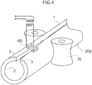
- Fig. 4 is a schematic perspective view showing an example of a pipe-making step.
- a hot-rolled steel sheet uncoiled from a hot coil is roll-formed using a forming roll (not shown in the drawing) in a direction such that a first surface is an outer peripheral surface 1 and a second surface is an inner peripheral surface 2, thereby making an open pipe. Abutting portions 3 of the open pipe are subjected to electric resistance welding using a power feed terminal 60 and a welding roll 70, thereby obtaining an electric resistance welded steel pipe 200.
- the production method A may include other steps, if necessary.
- Examples of the other steps include a step of subjecting the electric resistance welded portion of the electric resistance welded steel pipe to seam heat treatment after the pipe-making step, and a step of adjusting the shape of the electric resistance welded steel pipe by a sizing roll after the pipe-making step.
- Slabs were produced by continuous casting of molten steel having chemical compositions of Steel A to Steel O set forth in Table 1.
- REM in Steel L is specifically Ce.
- Each of the slabs described above was heated in a heating furnace, the heated slab was hot-rolled using multiple hot rolling mills to obtain a hot-rolled steel sheet, the obtained hot-rolled steel sheet was air-cooled and then water-cooled, and the water-cooled hot-rolled steel sheet was coiled, whereby a hot coil consisting of the hot-rolled steel sheet was obtained.
- the heating temperature in heating the slab, the finish rolling temperature in the hot-rolling, the cooling rates in water-cooling the hot-rolled steel sheet (V1 and V2), and the coiling temperature in coiling the water-cooled hot-rolled steel sheet are respectively set forth in Table 2.
- the upper surface of the hot-rolled steel sheet was set as a first surface
- the cooling rate of the first surface was set as V1
- the lower surface of the hot-rolled steel sheet was set as a second surface
- the cooling rate of the second surface was set as V2.
- the water-cooling of the hot-rolled steel sheet was performed by spraying the upper surface (i.e., first surface) and the lower surface (i.e., second surface) of the hot-rolled steel sheet, respectively, with a water-cooling shower.
- the water flow density of the water-cooling shower for the upper surface and the water flow density of the water-cooling shower for the lower surface were respectively adjusted, so that V1 and V2 were adjusted to be values set forth in Table 2.
- a conventional standard condition of water-cooling is a condition of Test Number 12 (Comparative Example).
- the hot-rolled steel sheet was uncoiled from the hot coil described above, the uncoiled hot-rolled steel sheet was roll-formed in a direction such that the first surface is an outer peripheral surface and the second surface is an inner peripheral surface of a pipe to thereby make an open pipe, and abutting portions of the obtained open pipe was subjected to electric resistance welding to form an electric resistance welded portion, thereby obtaining an electric resistance welded steel pipe (hereinafter also referred to as "electric resistance welded steel pipe before shape adjustment").
- an electric resistance welded steel pipe i.e., as-rolled electric resistance welded steel pipe having an outer diameter of 406.4 mm and a wall thickness of 15.9 mm.
- the above production step does not affect the chemical composition of a steel. Accordingly, the chemical composition of the base metal portion of the obtained electric resistance welded steel pipe can be considered to be the same as the chemical composition of the molten steel which is a raw material.
- the ferrite fraction (hereinafter also referred to as "F fraction") was measured, and the kind of the balance was confirmed.
- the maximum Vickers hardness of the inner surface layer of the base metal portion (HV) and the maximum Vickers hardness of the outer surface layer of the base metal portion (HV) were respectively measured based on the measurement method described above.
- the outer-inner hardness difference was calculated based on the measurement result by the following Formula.
- HV Outer-inner Hardness Difference
- the YS (MPa) and the TS (MPa) in the pipe axis direction of the electric resistance welded steel pipe were respectively measured based on the measurement method described above.
- a full thickness specimen having a size of 120 mm (pipe circumferential direction) ⁇ 25 mm (pipe axis direction) was sampled from the base metal 180° position of the electric resistance welded steel pipe.
- the electric resistance welded steel pipe of each Example which satisfies the chemical composition and the metallographic microstructure of the base metal portion in the disclosure, satisfies the YS (i.e., from 415 to 550 MPa) and the TS (i.e., from 461 to 625 MPa) in the disclosure, has the maximum Vickers hardness of the inner surface layer of the base metal portion of 248 HV or less, and has the outer-inner hardness difference of 5 HV or more, had excellent SSC resistance.
- Test Number 12 Comparative Example
- the SSC resistance was deteriorated.
- the reason thereof is considered that the maximum Vickers hardness of the inner surface layer exceeded the upper limit, both the TS and the YS exceeded the upper limit, and the outer-inner hardness difference was less than 5 HV.
- Test Numbers 9, 10, and 15 are all Comparative Examples in which the TS and the YS exceeded the upper limit, and Test Numbers 25 and 26 are Comparative Examples in which the TS and the YS were lower than the lower limit.
Landscapes
- Chemical & Material Sciences (AREA)
- Engineering & Computer Science (AREA)
- Materials Engineering (AREA)
- Mechanical Engineering (AREA)
- Metallurgy (AREA)
- Organic Chemistry (AREA)
- Physics & Mathematics (AREA)
- Thermal Sciences (AREA)
- Crystallography & Structural Chemistry (AREA)
- Manufacturing & Machinery (AREA)
- Heat Treatment Of Steel (AREA)
Abstract
Description
- The present disclosure relates to an as-rolled electric resistance welded steel pipe for a line pipe.
- Crude oil or natural gas produced in recent years includes wet hydrogen sulfide (H2S). An environment including hydrogen sulfide is referred to as a sour environment.
- A pipeline for transporting drilled crude oil or natural gas is exposed to such a sour environment. Thus, for a steel pipe for a line pipe, which is used in the production of a pipeline, resistance to a sour environment (sour resistance) is required.
- For example, Japanese Patent Application Laid-Open (
JP-A) No. 2013-11005 - Patent Document 1:
JP-A No. 2013-11005 - The concept of "sour resistance" includes resistance to hydrogen induced cracking (hereinafter also referred to as "HIC") generated mainly in the central portion of the wall thickness of the steel pipe (hereinafter also referred to as "HIC resistance") and resistance to sulfide stress cracking (hereinafter also referred to as "SSC") generated mainly from the inner peripheral surface of the steel pipe as the initiating point (hereinafter also referred to as "SSC resistance").
- Regarding this point, in
Patent Document 1, only the HIC resistance is evaluated, and the SSC resistance is not evaluated as the sour resistance. Thus, the high-strength hot-rolled steel sheet for a welded steel pipe for a line pipe ofPatent Document 1 may have low SSC resistance. - From the viewpoint of the improvement in transport efficiency and the improvement in operation efficiency, for an electric resistance welded steel pipe for a line pipe, a certain amount of high strength (for example, a yield strength in a pipe axis direction of 415 MPa or more, and a tensile strength in the pipe axis direction of 461 MPa or more) is required.
- In contrast, from the viewpoint of a bending deformation property and the suppression of buckling in the case of laying a pipeline formed using the electric resistance welded steel pipe for a line pipe, for the electric resistance welded steel pipe for a line pipe, not-too-high strength (for example, the yield strength in the pipe axis direction of 550 MPa or less, and the tensile strength in the pipe axis direction of 625 MPa or less) is also required.
- Therefore, an object of the disclosure is to provide an as-rolled electric resistance welded steel pipe for a line pipe, which has a yield strength in a pipe axis direction of from 415 to 550 MPa, which has a tensile strength in the pipe axis direction of from 461 to 625 MPa, and which has excellent SSC resistance.
- Means of solving the problem described above includes the following aspects.
- <1> An as-rolled electric resistance welded steel pipe for a line pipe, the steel pipe comprising a base metal portion and an electric resistance welded portion,
wherein a chemical composition of the base metal portion consists of, in terms of % by mass:- from 0.01 to 0.10% of C,
- from 0.01 to 0.40% of Si,
- from 0.50 to 2.00% of Mn,
- from 0 to 0.030% of P,
- from 0 to 0.0015% of S,
- from 0.010 to 0.050% of Al,
- from 0.0030 to 0.0080% of N,
- from 0.010 to 0.050% of Nb,
- from 0.005 to 0.020% of Ti,
- from 0 to 0.20% of Ni,
- from 0 to 0.20% of Mo,
- from 0 to 0.0050% of Ca,
- from 0 to 1.00% of Cr,
- from 0 to 0.100% of V,
- from 0 to 1.00% of Cu,
- from 0 to 0.0050% of Mg,
- from 0 to 0.0100% of REM, and
- the balance being Fe and impurities, wherein:
- in a metallographic microstructure of the base metal portion, an areal ratio of polygonal ferrite is from 80% to 98%, the balance is composed of at least one of bainite or pearlite,
- a yield strength in a pipe axis direction is from 415 to 550 MPa, a tensile strength in the pipe axis direction is from 461 to 625 MPa, and
- a maximum Vickers hardness of an inner surface layer of the base metal portion is 248 HV or less and is smaller than a maximum Vickers hardness of an outer surface layer of the base metal portion by 5 HV or more.
- <2> The as-rolled electric resistance welded steel pipe for a line pipe according to <1>, wherein the chemical composition of the base metal portion contains, in terms of % by mass, one or more selected from the group consisting of:
- more than 0% but equal to or less than 0.20% of Ni,
- more than 0% but equal to or less than 0.20% of Mo,
- more than 0% but equal to or less than 0.0050% of Ca,
- more than 0% but equal to or less than 1.00% of Cr,
- more than 0% but equal to or less than 0.10% of V,
- more than 0% but equal to or less than 1.00% of Cu,
- more than 0% but equal to or less than 0.0050% of Mg, and
- more than 0% but equal to or less than 0.0100% of REM.
- <3> The as-rolled electric resistance welded steel pipe for a line pipe according to <1> or <2>, wherein the chemical composition of the base metal portion contains, in terms of % by mass, one or more selected from the group consisting of:
- from 0.001 to 0.20% of Ni, and
- from 0.1 to 0.20% of Mo.
- <4> The as-rolled electric resistance welded steel pipe for a line pipe according to any one of <1> to <3>, wherein the chemical composition of the base metal portion contains, in terms of % by mass, from 0.0005 to 0.0050% of Ca.
- <5> The as-rolled electric resistance welded steel pipe for a line pipe according to any one of <1> to <4>, wherein a wall thickness is from 10 to 25 mm, and an outer diameter is from 114.3 mm to 660.4 mm.
- According to the disclosure, an as-rolled electric resistance welded steel pipe for a line pipe, which has a yield strength in a pipe axis direction of from 415 to 550 MPa, which has a tensile strength in the pipe axis direction of from 461 to 625 MPa, and which has excellent SSC resistance, is provided.
-
-
Fig. 1 is a scanning electron micrograph (a magnification of 500 times) showing an example of a metallographic microstructure of a base metal portion in the disclosure. -
Fig. 2 is a scanning electron micrograph (a magnification of 2,000 times) obtained by enlarging a part ofFig. 1 . -
Fig. 3 is a schematic front view of a tensile test specimen used for a tensile test in the disclosure. -
Fig. 4 is a schematic perspective view showing an example of a pipe-making step for producing an electric resistance welded steel pipe of the disclosure. - A numerical range expressed by "from x to y" herein includes the values of x and y in the range as the minimum and maximum values, respectively.
- The content of a component (element) expressed by "%" herein means "% by mass".
- The content of C (carbon) in a base metal portion may be herein occasionally expressed as "C content". The content of another element in the base metal portion may be expressed similarly.
- The term "step" herein encompasses not only an independent step but also a step of which the desired object is achieved even in a case in which the step is incapable of being definitely distinguished from another step.
- Herein, an "as-rolled electric resistance welded steel pipe for a line pipe" may be simply referred to as an "electric resistance welded steel pipe" or an "as-rolled electric resistance welded steel pipe".
- Herein, the as-rolled electric resistance welded steel pipe refers to an electric resistance welded steel pipe which is not subjected to heat treatment other than seam heat treatment after pipe-making.
- Herein, the "pipe-making" refers to a process of making an open pipe by roll-forming of a hot-rolled steel sheet and forming an electric resistance welded portion by electric resistance welding of abutting portions of the obtained open pipe.
- Herein, the "roll-forming" refers to forming of a hot-rolled steel sheet into an open pipe shape by bending work.
- An electric resistance welded steel pipe (i.e., an as-rolled electric resistance welded steel pipe for a line pipe) of the disclosure includes a base metal portion and an electric resistance welded portion, wherein a chemical composition of the base metal portion consists of, in terms of% by mass: from 0.01 to 0.10% of C, from 0.01 to 0.40% of Si, from 0.50 to 2.00% of Mn, from 0 to 0.030% of P, from 0 to 0.0015% of S, from 0.010 to 0.050% of Al, from 0.0030 to 0.0080% of N, from 0.010 to 0.050% of Nb, from 0.005 to 0.020% of Ti, from 0 to 0.20% of Ni, from 0 to 0.20% of Mo, from 0 to 0.0050% of Ca, from 0 to 1.00% of Cr, from 0 to 0.100% of V, from 0 to 1.00% of Cu, from 0 to 0.0050% of Mg, from 0 to 0.0100% of REM, and the balance being Fe and impurities, wherein: in a metallographic microstructure of the base metal portion, an areal ratio of polygonal ferrite is from 80% to 98%, the balance is composed of at least one of bainite or pearlite, a yield strength in a pipe axis direction (hereinafter also referred to as "YS") is from 415 to 550 MPa, a tensile strength in the pipe axis direction (hereinafter also referred to as "TS") is from 461 to 625 MPa, and a maximum Vickers hardness of an inner surface layer of the base metal portion is 248 HV or less and is smaller than a maximum Vickers hardness of an outer surface layer of the base metal portion by 5 HV or more.
- In the electric resistance welded steel pipe of the disclosure, the base metal portion refers to a portion other than the electric resistance welded portion and a heat affected zone in the electric resistance welded steel pipe.
- The heat affected zone (hereinafter also referred to as "HAZ") refers to a portion affected by heat caused by electric resistance welding (affected by heat caused by the electric resistance welding and seam heat treatment in a case in which the seam heat treatment is performed after the electric resistance welding).
- In the electric resistance welded steel pipe of the disclosure, the maximum Vickers hardness of the inner surface layer of the base metal portion means a value measured as follows.
- First, as measurement points of the Vickers hardness, in a C cross-section of the electric resistance welded steel pipe (i.e., a cross-section perpendicular to the pipe axis direction), nine points at 1 mm pitch, which are arranged on the circumference at a depth of 0.1 mm from an inner peripheral surface of the electric resistance welded steel pipe and centered at a base metal 180° position (i.e., a position shifted from the electric resistance welded portion by 180° in a pipe circumferential direction), are selected. A specimen including the above-described selected nine measurement points is sampled from the electric resistance welded steel pipe. In each of the nine measurement points in the specimen, the Vickers hardness is measured in conformity with JIS Z2244 (2009) under the condition of a test force of 100 gf (= 0.98 N) with the pipe axis direction as a test direction. The maximum value among the obtained nine measurement results is regarded as the maximum Vickers hardness of the inner surface layer of the base metal portion.
- In other words, the maximum Vickers hardness of the inner surface layer of the base metal portion is, approximately speaking, a maximum Vickers hardness in the vicinity of the inner peripheral surface of the base metal portion.
- In the electric resistance welded steel pipe of the disclosure, the maximum Vickers hardness of the outer surface layer of the base metal portion means a value measured in the same way as the maximum Vickers hardness of the inner surface of the base metal portion described above except that the "inner peripheral surface" is read as the "outer peripheral surface".
- In other words, the maximum Vickers hardness of the outer surface layer of the base metal portion is, approximately speaking, a maximum Vickers hardness in the vicinity of the outer peripheral surface of the base metal portion.
- The electric resistance welded steel pipe of the disclosure has a certain amount of strength (i.e., YS and TS in the ranges described above) and has excellent SSC resistance.
- In contrast to the electric resistance welded steel pipe of the disclosure, in a conventional electric resistance welded steel pipe for a line pipe (for example, the electric resistance welded steel pipe for a line pipe described in the above-described Patent Document 1), the HIC resistance as the sour resistance was considered, but the SSC resistance as the sour resistance was not considered.
- However, locations of generation of cracking are different in HIC (hydrogen induced cracking) and SSC (sulfide stress cracking). Specifically, HIC is generated mainly in the central portion of the wall thickness of the electric resistance welded steel pipe, whereas SSC is generated mainly from the inner peripheral surface of the electric resistance welded steel pipe as the initiating point. More specifically, in a state where a fluid containing wet hydrogen sulfide (specifically, crude oil or natural gas; hereinafter also referred to as "sour fluid") is in contact with the inner peripheral surface of the electric resistance welded steel pipe for a line pipe, SSC is generated from the inner peripheral surface as the initiating point.
- Therefore, even if an electric resistance welded steel pipe has excellent HIC resistance, the electric resistance welded steel pipe may have poor SSC resistance.
- In the electric resistance welded steel pipe of the disclosure, the maximum Vickers hardness of the inner surface layer of the base metal portion is 248 HV or less, and the maximum Vickers hardness of the inner surface layer of the base metal portion is smaller than the maximum Vickers hardness of the outer surface layer of the base metal portion by 5 HV or more. As a result, under a state where a sour fluid is in contact with the inner peripheral surface of the electric resistance welded steel pipe, SSC which is cracking generated from the inner peripheral surface as the initiating point is suppressed (i.e., the SSC resistance is improved).
- Moreover, SSC tends to be easily generated as the strength of the electric resistance welded steel pipe becomes higher.
- Regarding this point, in the electric resistance welded steel pipe of the disclosure, the YS is limited to 550 MPa or less, and the TS is limited to 625 MPa or less, respectively. As a result, the SSC resistance is improved.
- In contrast, in the electric resistance welded steel pipe of the disclosure, the maximum Vickers hardness of the inner surface layer of the base metal portion is smaller than the maximum Vickers hardness of the outer surface layer of the base metal portion by 5 HV or more, so that the maximum Vickers hardness of the outer surface layer of the base metal portion is relatively secured to a certain degree.
- As a result, a certain amount of high strength (specifically, YS of 415 MPa or more, and TS of 461 MPa or more) is secured as the entire electric resistance welded steel pipe.
- In contrast to the electric resistance welded steel pipe of the disclosure, in the conventional electric resistance welded steel pipe, the maximum Vickers hardness of the inner surface layer of the base metal portion was almost the same as the maximum Vickers hardness of the outer surface layer of the base metal portion, and the condition that "the maximum Vickers hardness of the inner surface layer of the base metal portion is smaller than the maximum Vickers hardness of the outer surface layer of the base metal portion by 5 HV or more" was not satisfied owing to the following circumstances.
- The electric resistance welded steel pipe is produced by using a hot coil consisting of a hot-rolled steel sheet as a raw material and subjecting the hot-rolled steel sheet, uncoiled from the hot coil, to pipe-making (i.e., roll-forming and electric resistance welding). One of two surfaces of the hot-rolled steel sheet uncoiled from the hot coil (hereinafter also referred to as "first surface") becomes an outer surface of the electric resistance welded steel pipe, and the other of the two surfaces (hereinafter also referred to as "second surface") becomes an inner surface of the electric resistance welded steel pipe. A production process of the hot coil includes respective stages of hot-rolling, cooling, and coiling in this order. From the viewpoint of suppressing warpage of the hot-rolled steel sheet after cooling or from the viewpoint of the productivity, this cooling was conventionally performed by water-cooling the two surfaces of the hot-rolled steel sheet obtained by hot-rolling at cooling rates which are almost the same. Under such a circumstance, in the conventional electric resistance welded steel pipe, the maximum Vickers hardness of the inner surface layer of the base metal portion was almost the same as the maximum Vickers hardness of the outer surface layer of the base metal portion (i.e., the condition that "the maximum Vickers hardness of the inner surface layer of the base metal portion is smaller than the maximum Vickers hardness of the outer surface layer of the base metal portion by 5 HV or more" was not satisfied).
- For the above-described conventional electric resistance welded steel pipe, the present inventors succeeded in making the maximum Vickers hardness of the inner surface layer of the base metal portion smaller than the maximum Vickers hardness of the outer surface layer of the base metal portion by 5 HV or more by providing a difference between the cooling rates for the two surfaces when the two surfaces of the hot-rolled steel sheet obtained by hot-rolling are cooled (specifically, by making the cooling rate of the second surface corresponding to the inner peripheral surface slower than the cooling rate of the first surface corresponding to the outer peripheral surface). Furthermore, the present inventors found that, virtually, the warpage of the hot-rolled steel sheet after cooling is not matter too much because the cooled hot-rolled steel sheet is subsequently coiled.
- The electric resistance welded steel pipe of the disclosure was completed based on the above-described knowledge of the present inventors.
- Not only the maximum Vickers hardness of the inner surface layer of the base metal portion but also the chemical composition of the base metal portion, the metallographic microstructure of the base metal portion, and being the as-rolled electric resistance welded steel pipe contribute to the SSC resistance.
- Moreover, the chemical composition of the base metal portion, the metallographic microstructure of the base metal portion, and being the as-rolled electric resistance welded steel pipe also contribute to the achievement of the YS in the range described above and the TS in the range described above.
- The chemical composition of the base metal portion and the metallographic microstructure of the base metal portion will be described below.
- The chemical composition of the base metal portion will be described below.
- C enhances the strength of steel. In a case in which a C content is too low, the effect cannot be obtained. Accordingly, the C content is 0.01% or more. The C content is preferably 0.03% or more, and more preferably 0.04% or more.
- In contrast, in a case in which the C content is too high, a carbide is generated, and the toughness and ductility of steel are decreased. Accordingly, the C content is 0.10% or less. The C content is preferably 0.09%, and still more preferably 0.08% or less.
- Si deoxidizes steel. In a case in which a Si content is too low, the effect cannot be obtained. Accordingly, the Si content is 0.01% or more. The Si content is preferably 0.02% or more, and still more preferably 0.10% or more.
- In contrast, in a case in which the Si content is too high, the toughness of steel is decreased. Accordingly, the Si content is 0.40% or less. The Si content is preferably 0.38% or less, and more preferably 0.35% or less.
- Mn enhances the hardenability of steel and enhances the strength of steel. In a case in which a Mn content is too low, the effect cannot be obtained. Accordingly, the Mn content is 0.50% or more. The Mn content is preferably 0.60% or more, and more preferably 0.80% or more.
- In contrast, in a case in which the Mn content is too high, the toughness and SSC resistance of steel are decreased. Accordingly, the Mn content is 2.00% or less. The Mn content is preferably 1.80% or less, and more preferably 1.50% or less.
- P is an impurity. P segregates in a grain boundary and embrittles the grain boundary. Thus, P decreases the toughness and SSC resistance of steel. Accordingly, a P content is preferably small. Specifically, the P content is 0.030% or less. The P content is preferably 0.021% or less, more preferably 0.015% or less, and still more preferably 0.010% or less.
- In contrast, the P content may be 0%. From the viewpoint of reducing a dephosphorization cost, the P content may be more than 0%, and may be 0.001% or more.
- S is an impurity. S binds to Mn to form a Mn-based sulfide. The Mn-based sulfide is diffluent. Thus, the toughness and SSC resistance of steel are decreased. Accordingly, a S content is preferably as low as possible. Specifically, the S content is 0.0015% or less. The S content is preferably 0.0010% or less, and more preferably 0.0008% or less.
- In contrast, the S content may be 0%. From the viewpoint of reducing a desulfurization cost, the S content may be more than 0%, may be 0.0001% or more, and may be 0.0003% or more.
- Al deoxidizes steel. In a case in which an Al content is too low, the effect cannot be obtained. Accordingly, the Al content is 0.010% or more. The Al content is preferably 0.012% or more, and more preferably 0.013% or more.
- In contrast, in a case in which the Al content is too high, an Al nitride is coarsened, and the toughness of steel is decreased. Accordingly, the Al content is 0.050% or less. The Al content is preferably 0.040% or less, more preferably 0.035% or less, and still more preferably 0.030% or less.
- The Al content herein means the content of total Al in the steel.
- N enhances the strength of steel by solid-solution strengthening. In a case in which a N content is too low, the effect cannot be obtained. Accordingly, the N content is 0.0030% or more.
- In contrast, in a case in which the N content is too high, a carbonitride is coarsened, and the SSC resistance is decreased. Accordingly, the N content is 0.0080% or less. The N content is preferably 0.0070% or less, more preferably 0.0060% or less, and still more preferably 0.0040% or less.
- Nb binds to C and N in the steel to form a fine Nb carbonitride. The fine Nb carbonitride enhances the strength of steel by dispersion strengthening. In a case in which a Nb content is too low, the effect cannot be obtained. Accordingly, the Nb content is 0.010% or more. The Nb content is preferably 0.020% or more, and more preferably 0.030% or more.
- In contrast, in a case in which the Nb content is too high, the Nb carbonitride is coarsened, and the SSC resistance of steel is decreased. Furthermore, in a case in which the Nb content is too high, the toughness of the electric resistance welded portion is decreased. Accordingly, the Nb content is 0.050% or less. The Nb content is preferably 0.045% or less, and more preferably 0.040% or less.
- Ti binds to N in the steel to form a Ti nitride and/or Ti carbonitride. The Ti nitride and/or Ti carbonitride refines crystal grains of the steel. In a case in which a Ti content is too low, the effect cannot be obtained. Accordingly, the Ti content is 0.005% or more. The Ti content is preferably 0.007% or more, and more preferably 0.010% or more.
- In contrast, in a case in which the Ti content is too high, a coarse Ti nitride and/or Ti carbonitride is formed. Thus, the SSC resistance of steel is decreased. Accordingly, the Ti content is 0.020% or less. The Ti content is preferably 0.018% or less, and more preferably 0.016% or less.
- Ni is an optional element and may not be contained. In other words, a Ni content may be 0%.
- In a case in which Ni is contained, Ni enhances the strength of steel by solid-solution strengthening. Ni further enhances the toughness of steel. From the viewpoint of the effect, the Ni content is preferably more than 0%, more preferably 0.001% or more, more preferably 0.005% or more, still more preferably 0.01% or more, and still more preferably 0.05% or more.
- In contrast, in a case in which the Ni content is too high, the weldability of steel is decreased. Accordingly, the Ni content is 0.20% or less. The Ni content is preferably 0.18% or less, and still more preferably 0.15% or less.
- Mo is an optional element and may not be contained. In other words, a Mo content may be 0%.
- In a case in which Mo is contained, Mo enhances the hardenability of steel and enhances the strength of steel. Furthermore, since micro segregation of Mo is difficult to be generated, generation of HIC caused by center segregation is suppressed. From the viewpoint of the effect, the Mo content is preferably more than 0%, more preferably 0.10% or more, and still more preferably 0.12% or more.
- In contrast, since Mo is expensive, in a case in which Mo is excessively included, the production cost increases. Accordingly, the Mo content is 0.20% or less. The Mo content is preferably 0.18% or less, and more preferably 0.15% or less.
- Ca is an optional element and may not be contained. In other words, a Ca content may be 0%.
- In a case in which Ca is contained, Ca makes the form of MnS that becomes a initiating point of generation of SSC into a spherical shape and suppresses the generation of SSC. Ca further forms CaS and suppresses generation of MnS. From the viewpoint of the effect, the Ca content is preferably more than 0%, more preferably 0.0005% or more, still more preferably 0.0010% or more, and still more preferably 0.0020% or more.
- In contrast, in a case in which the Ca content is too high, the effect is saturated, and the production cost increases. Accordingly, the Ca content is 0.0050% or less. The Ca content is preferably 0.0045% or less.
- Cr is an optional element and may not be contained. In other words, a Cr content may be 0%.
- In a case in which Cr is contained, Cr contributes to improvement in hardenability. From the viewpoint of such an effect, the Cr content is preferably more than 0%, and more preferably 0.01% or more.
- In contrast, in a case in which the Cr content is too high, the toughness of the electric resistance welded portion may be deteriorated by Cr-based inclusions generated in the electric resistance welded portion. Accordingly, the Cr content is 1.00% or less. The Cr content is preferably 0.50% or less, more preferably 0.30% or less, and still more preferably 0.20% or less.
- V is an optional element and may not be contained. In other words, a V content may be 0%.
- In a case in which V is contained, V contributes to improvement in toughness. From the viewpoint of such an effect, the V content is preferably more than 0%, more preferably 0.001% or more, and still more preferably 0.005% or more.
- In contrast, in a case in which the V content is too high, the toughness may be deteriorated by a V carbonitride. Accordingly, the V content is 0.100% or less. The V content is preferably 0.070% or less, more preferably 0.050% or less, and still more preferably 0.030% or less.
- Cu is an optional element and may not be contained. In other words, a Cu content may be 0%.
- In a case in which Cu is contained, Cu contributes to improvement in the strength of the base metal portion. From the viewpoint of such an effect, the Cu content is preferably more than 0%, more preferably 0.01% or more, and still more preferably 0.05% or more.
- In contrast, in a case in which the Cu content is too high, fine Cu particles are generated, and the toughness may be significantly deteriorated. Accordingly, the Cu content is 1.00% or less. The Cu content is preferably 0.70% or less, more preferably 0.50% or less, and still more preferably 0.30% or less.
- Mg is an optional element and may not be contained. In other words, a Mg content may be 0%.
- In a case in which Mg is contained, Mg functions as a deoxidizer and a desulfurizer. Moreover, Mg forms a fine oxide and also contributes to improvement in the toughness of an HAZ. From the viewpoint of the effect, the Mg content is preferably more than 0%, more preferably 0.0001% or more, and still more preferably 0.0010% or more.
- In contrast, in a case in which the Mg content is too high, the oxide becomes easy to be aggregated or coarsened, and therefore, the decrease in HIC resistance or the decrease in the toughness of the base metal portion or the HAZ may be caused. Accordingly, the Mg content is 0.0050% or less. The Mg content is preferably 0.0030% or less.
- REM is an optional element and may not be contained. In other words, an REM content may be 0%.
- "REM" refers to a rare earth element, i.e., at least one element selected from the group consisting of Sc, Y, La, Ce, Pr, Nd, Pm, Sm, Eu, Gd, Tb, Dy, Ho, Er, Tm, Yb, and Lu.
- In a case in which REM is contained, REM functions as a deoxidizer and a desulfurizer. From the viewpoint of such an effect, the REM content is preferably more than 0%, more preferably 0.0001% or more, and still more preferably 0.0010% or more.
- In contrast, in a case in which REM is too high, a coarse oxide is generated, and therefore, the decrease in the HIC resistance or the decrease in the toughness of the base metal portion or the HAZ may be caused. Accordingly, the REM content is 0.0100% or less. The REM content is preferably 0.0070% or less, and more preferably 0.0050% or less.
- The chemical composition of the base metal portion may contain one or more selected from the group consisting of: more than 0% but equal to or less than 0.20% of Ni, more than 0% but equal to or less than 0.20% of Mo, more than 0% but equal to or less than 0.0050% of Ca, more than 0% but equal to or less than 1.00% of Cr, more than 0% but equal to or less than 0.100% of V, more than 0% but equal to or less than 1.00% of Cu, more than 0% but equal to or less than 0.0050% of Mg, and more than 0% but equal to or less than 0.0100% of REM.
- The more preferred content of each optional element has been described above.
- In the chemical composition of the base metal portion, the balance excluding each element described above is Fe and impurities.
- The impurities refer to components which are contained in a raw material (for example, ore, scrap, and the like) or mixed into in a production step, and which are not intentionally incorporated into a steel.
- Examples of the impurities include any elements other than the elements described above. Elements as the impurities may be only one kind, or may be two or more kinds.
- Examples of the impurities include O, B, Sb, Sn, W, Co, As, Pb, Bi, and H.
- Among the elements described above, O is preferably controlled to have a content of 0.006% or less.
- For the other elements, typically, Sb, Sn, W, Co, or As may be included in a content of 0.1 % or less, Pb or Bi may be included in a content of 0.005% or less, B may be included in a content of 0.0003% or less, H may be included in a content of 0.0004% or less, and the contents of the other elements need not particularly be controlled as long as being in a usual range.
- In the electric resistance welded steel pipe of the disclosure, in the metallographic microstructure of the base metal portion, an areal ratio of polygonal ferrite (hereinafter also referred to as "ferrite fraction") is from 80 to 98%, and the balance is composed of at least one of bainite or pearlite.
- A YS of 550 MPa or less and a TS of 625 MPa or less can be achieved by allowing a ferrite fraction to be 80% or more. The ferrite fraction is preferably 81% or more, and more preferably 82% or more.
- In contrast, a YS of 415 MPa or more and a TS of 461 MPa or more can be achieved by allowing a ferrite fraction to be 98% or less. The ferrite fraction is preferably 97% or less, and more preferably 95% or less.
- The balance in the metallographic microstructure of the base metal portion is composed of at least one of bainite or pearlite. As a result, the SSC resistance is improved compared to a case in which the balance contains, for example, martensite.
- The concept of "bainite" herein includes bainitic ferrite, upper bainite, and lower bainite.
- The concept of "pearlite" herein includes pseudo-pearlite.
- The above-described metallographic microstructure of the base metal portion relates to the electric resistance welded steel pipe of the disclosure being an as-rolled electric resistance welded steel pipe (i.e., not subjected to heat treatment other than seam heat treatment after pipe-making).
- In an electric resistance welded steel pipe formed by being subjected to heat treatment other than seam heat treatment after pipe-making unlike the electric resistance welded steel pipe of the disclosure (as-rolled electric resistance welded steel pipe), martensite may be formed as the metallographic microstructure of the base metal portion. The electric resistance welded steel pipe in this case has poor SSC resistance.
- The measurement of the ferrite fraction and the identification of the balance in the metallographic microstructure of the base metal portion are performed as follows.
- A metallographic microstructure of the central portion of the wall thickness in an L cross-section at a base metal 180° position is nital-etched, and micrographs of the nital-etched metallographic microstructure (hereinafter also referred to as "metallographic micrographs") are observed with a scanning electron microscope (SEM) at a magnification of 500 times. Metallographic micrographs corresponding to ten 500-times visual fields (corresponding to actual cross-sectional area of 0.48 mm2) are taken. The measurement of the ferrite fraction and the identification of the balance are performed by performing image processing of the metallographic micrographs that were taken. The image processing is performed using, for example, a small-sized general-purpose image analysis apparatus LUZEX AP manufactured by NIRECO CORPORATION.
-
Fig. 1 is a scanning electron micrograph (SEM micrograph; a magnification of 500 times) showing an example of a metallographic microstructure of a base metal portion in the disclosure, andFig. 2 is a SEM micrograph (a magnification of 2,000 times) obtained by enlarging a region ofFig. 1 . - The SEM micrograph (500 times) in
Fig. 1 is one (one visual field) of SEM micrographs used in the measurement of the ferrite fraction and the identification of the balance in Test Number 22 described later. - As shown in
Fig. 1 andFig. 2 , the metallographic microstructure according to this example is a metallographic microstructure which is mainly composed of polygonal ferrite and in which the balance is pearlite. - More specifically, because cementite is not precipitated in a grain boundary of polygonal ferrite and lamellar cementite in pearlite in the balance is not divided, the metallographic microstructure is revealed to be a metallographic microstructure which is not subjected to heat treatment after pipe-making (i.e., a metallographic microstructure of an as-rolled electric resistance welded steel pipe).
- Being an as-rolled electric resistance welded steel pipe can also be confirmed by not observing yield elongation in a case in which a pipe axis direction tensile test is performed.
- In an as-rolled electric resistance welded steel pipe, yield elongation is not observed in a case in which a pipe axis direction tensile test is performed.
- In contrast, in an electric resistance welded steel pipe which is subjected to heat treatment after pipe-making, yield elongation is observed in a case in which a pipe axis direction tensile test is performed.
- In the electric resistance welded steel pipe of the disclosure, a maximum Vickers hardness of an inner surface layer of the base metal portion is 248 HV or less, and the Vickers hardness of the inner surface layer of the base metal portion is smaller than a maximum Vickers hardness of an outer surface layer of the base metal portion by 5 HV or more.
- Each of the maximum Vickers hardness of the inner surface layer of the base metal portion and the maximum Vickers hardness of the outer surface layer of the base metal portion has been described above.
- A difference obtained by subtracting the Vickers hardness of the inner surface layer of the base metal portion from the maximum Vickers hardness of the outer surface layer of the base metal portion (i.e., the maximum Vickers hardness of the outer surface layer of the base metal portion - the Vickers hardness of the inner surface layer of the base metal portion) is hereinafter also referred to as an "outer-inner hardness difference".
- For example, "the Vickers hardness of the inner surface layer of the base metal portion is smaller than the maximum Vickers hardness of the outer surface layer of the base metal portion by 5 HV or more" is hereinafter also referred to as "the outer-inner hardness difference is 5 HV or more".
- In a case in which the maximum Vickers hardness of the inner surface layer of the base metal portion exceeds 248 HV, the toughness of steel is decreased, and the SSC resistance of the electric resistance welded steel pipe is decreased. Accordingly, the maximum Vickers hardness of the inner surface layer is 248 HV or less. The maximum Vickers hardness of the inner surface layer is preferably 245 HV or less, and more preferably 220 HV or less.
- The lower limit of the maximum Vickers hardness of the inner surface layer is not particularly limited. From the viewpoint of more improving the strength of the electric resistance welded steel pipe (i.e., YS and TS), the maximum Vickers hardness of the inner surface layer is preferably 175 HV or more, more preferably 180 HV or more, and still more preferably 185 HV or more.
- In a case in which the outer-inner hardness difference is less than 5 HV, depending on the value of the maximum Vickers hardness of the inner surface layer of the base metal portion, at least one of the deterioration of the SSC resistance, the deficiency of the YS, or the deficiency of the TS occurs. Accordingly, the outer-inner hardness difference is 5 HV or more, and preferably 6 HV or more.
- The upper limit of the outer-inner hardness difference is not particularly restricted. From the viewpoint of the production suitability of the electric resistance welded steel pipe, the outer-inner hardness difference is preferably 20 HV or less, more preferably 15 HV or less, and still more preferably 10 HV or less.
- The maximum Vickers hardness of the outer surface layer of the base metal portion may satisfy the maximum Vickers hardness of the inner surface layer of the base metal portion and the outer-inner hardness difference described above, and others are not particularly restricted.
- The maximum Vickers hardness of the outer surface layer of the base metal portion is preferably from 180 MPa to 250 MPa, and more preferably from 210 MPa to 230 MPa.
- As described above, in the electric resistance welded steel pipe of the disclosure, the Vickers hardness of the inner surface layer of the base metal portion is smaller than the maximum Vickers hardness of the outer surface layer of the base metal portion by 5 HV or more.
- In the electric resistance welded steel pipe of the disclosure, the maximum Vickers hardness of the inner surface layer may be lower than the maximum Vickers hardness of the outer surface layer by 5 HV or more in not only the base metal portion but also the electric resistance welded portion.
- For example, in the case of producing the electric resistance welded steel pipe by production method A described later, the maximum Vickers hardness of the inner surface layer may be lower than the maximum Vickers hardness of the outer surface layer by 5 HV or more also in the electric resistance welded portion.
- The electric resistance welded steel pipe of the disclosure has a yield strength in a pipe axis direction (YS) of from 415 to 550 MPa.
- A YS of 415 MPa or more secures the strength as the electric resistance welded steel pipe for a line pipe. The YS is preferably 430 MPa or more.
- In contrast, a YS of 550 MPa or less (i.e., not-too-high YS) is advantageous in view of the improvement in the SSC resistance or a bending deformation property and the suppression of buckling in the case of laying a pipeline formed using the electric resistance welded steel pipe for a line pipe. The YS is preferably 530 MPa or less.
- The electric resistance welded steel pipe of the disclosure has a tensile strength in a pipe axis direction (TS) of from 461 to 625 MPa.
- A TS of 461 MPa or more secures the strength as the electric resistance welded steel pipe for a line pipe. The TS is preferably 500 MPa or more, and more preferably 510 MPa or more.
- In contrast, a TS of 625 MPa or less (i.e., not-too-high TS) is advantageous in view of the improvement in the SSC resistance or a bending deformation property and the suppression of buckling in the case of laying a pipeline formed using the electric resistance welded steel pipe for a line pipe. The TS is preferably 620 MPa or less.
- The YS and the TS are measured by the following method.
- A full thickness tensile test specimen is sampled from the base metal 90° position of the electric resistance welded steel pipe. Specifically, the tensile test specimen is sampled such that a longitudinal direction of the tensile test specimen is parallel to the pipe axis direction of the electric resistance welded steel pipe and the shape of a cross-section of the tensile test specimen (i.e., a cross-section parallel to a width direction and a thickness direction of the tensile test specimen) is an arcuate shape.
-
Fig. 3 is a schematic front view of a tensile test specimen used for a tensile test. - A unit of numerical values in
Fig. 3 is mm. - As shown in
Fig. 3 , the length of a parallel part of the tensile test specimen is set to be 50.8 mm, and the width of the parallel part is set to be 38.1 mm. - The tensile test is conducted using the tensile test specimen in conformity with standard API, specification 5CT at ordinary temperature. The YS and the TS are determined based on the test result.
- The electric resistance welded steel pipe of the disclosure has preferably a yield ratio in a pipe axis direction (YR = (YS/TS) × 100) of 95% or less.
- A YR of 95% or less is advantageous in view of the suppression of buckling in the case of laying a pipeline formed using the electric resistance welded steel pipe for a line pipe.
- The wall thickness of the electric resistance welded steel pipe of the disclosure is preferably from 10 to 25 mm.
- The wall thickness is more preferably 12 mm or more.
- A wall thickness of 25 mm or less is advantageous in view of the production suitability of the electric resistance welded steel pipe (specifically, formability in formation of a hot-rolled steel sheet into a pipe shape). The wall thickness is more preferably 20 mm or less.
- The outer diameter of the electric resistance welded steel pipe of the disclosure is preferably from 114.3 to 660.4 mm (i.e., 4.5 to 26 inches).
- The outer diameter is preferably 152.4 mm (i.e., 6 inches) or more, and more preferably 254 mm (i.e., 10 inches) or more.
- The outer diameter is preferably 609.6 mm (i.e., 24 inches) or less, and more preferably 508 mm (i.e., 20 inches) or less.
- One example of a method of producing the electric resistance welded steel pipe of the disclosure is the following production method A.
- The production method A includes:
- a preparation step of preparing a slab having the chemical composition described above,
- a hot-rolling step of heating the prepared slab and hot-rolling the heated slab, thereby obtaining a hot-rolled steel sheet,
- a cooling step of cooling a first surface of the hot-rolled steel sheet at a cooling rate V1 and cooling a second surface which is the opposite side of the first surface of the hot-rolled steel sheet at a cooling rate V2 which is slower than the cooling rate V1,
- a coiling step of coiling the cooled hot-rolled steel sheet, thereby obtaining a hot coil consisting of the hot-rolled steel sheet, and
- a pipe-making step of uncoiling the hot-rolled steel sheet from the hot coil, roll-forming the uncoiled hot-rolled steel sheet in a direction such that the first surface is an outer peripheral surface and the second surface is an inner surface to thereby make an open pipe, and subjecting abutting portions of the obtained open pipe to electric resistance welding to form an electric resistance welded portion, thereby obtaining an electric resistance welded steel pipe.
- According to the production method A, since the hot-rolled steel sheet in which the hardness of the second surface is lower than the hardness of the first surface is easily produced, the electric resistance welded steel pipe in which the hardness of the inner peripheral surface is lower than the hardness of the outer peripheral surface is easily produced, and therefore, the electric resistance welded steel pipe of the disclosure having an outer-inner hardness difference of 5 HV or more is easily produced.
- In the production method A, the step of preparing a slab is a step of preparing a slab having the chemical composition described above.
- The step of preparing a slab may be a step of producing a slab or a step of simply preparing a slab produced in advance.
- In the case of producing a slab, for example, molten steel having the chemical composition described above is produced, and a slab is produced using the produced molten steel. In this case, the slab may be produced by continuous casting, or the slab may be produced by producing an ingot using molten steel and breaking down the ingot.
- In the production method A, the hot-rolling step is a step of heating the prepared slab described above and hot-rolling the heated slab, thereby obtaining a hot-rolled steel sheet.
- The heating temperature in heating the slab is preferably from 1,100 to 1,250°C.
- In a case in which the heating temperature is 1,100°C or more, refining of crystal grains during hot-rolling and precipitation strengthening after hot-rolling easily proceed, and therefore, the strength of steel is easily improved.
- In a case in which the heating temperature is 1,250°C or less, since coarsening of austenite grains can be more suppressed, crystal grains are easily refined, and therefore, the strength of steel is easily improved.
- The heating of the slab is performed by, for example, a heating furnace.
- In the hot-rolling step, a hot-rolled steel sheet is obtained by hot-rolling the heated slab described above.
- The hot-rolling is preferably performed under the condition that a finish rolling finishing temperature (hereinafter also referred to as "finish rolling temperature") is from 780 to 830°C.
- The hot-rolling is generally performed using a rough rolling mill and a finish rolling mill. Both the rough rolling mill and the finish rolling mill generally include multiple rolling stands in a row, and each of the rolling stands includes a pair of rolls. In this case, the finish rolling temperature (i.e., finish rolling finishing temperature) is a surface temperature of the hot-rolled steel sheet at the exit side of a final stand of the finish rolling mill.
- In a case in which the finish rolling temperature is 780°C or more, since the rolling resistance of the steel sheet can be reduced, the productivity is improved.
- Moreover, in a case in which the finish rolling temperature is 780°C or more, a phenomenon in which rolling is performed in a two-phase region of ferrite and austenite is suppressed, and the formation of a banded structure and the decrease in mechanical properties associated with the phenomenon can be suppressed.
- In contrast, in a case in which the finish rolling temperature is 830°C or less, since a phenomenon in which the steel becomes too hard is suppressed, a phenomenon in which the YS and/or TS of the electric resistance welded steel pipe to be obtained becomes too high is suppressed.
- In the hot-rolling, the rolling reduction in an austenite non-recrystallization temperature region is preferably from 70 to 80%. In this case, a non-recrystallization structure is refined.
- The cooling step is a step of cooling a first surface of the hot-rolled steel sheet at a cooling rate V1 and cooling a second surface which is the opposite side of the first surface of the hot-rolled steel sheet at a cooling rate V2 which is slower than the cooling rate V1.
- In the cooling step, the first surface may be an upper surface (a surface on the opposite side with respect to the gravity direction, the same shall apply hereinafter) and the second surface may be a lower surface (a surface oriented in the gravity direction, the same shall apply hereinafter), or the first surface may be the lower surface and the second surface may be the upper surface.
- Both the cooling of the first surface and the cooling of the second surface preferably include water-cooling.
- In this case, the hot-rolled steel sheet may be water-cooled immediately after the hot-rolling, or the hot-rolled steel sheet immediately after the hot-rolling may be first air-cooled and then water-cooled.
- The cooling rate V1 and the cooling rate V2 preferably satisfy the following Formula (1). As a result, the hot-rolled steel sheet in which the hardness of the second surface is lower than the hardness of the first surface is more easily produced, and therefore, the electric resistance welded steel pipe of the disclosure having an outer-inner hardness difference of 5 HV or more is more easily produced.

- (In Formula (1), V1 represents the cooling rate V1 (°C/s), and V2 represents the cooling rate V2 (°C/s).)
- The cooling rate V1 is preferably from 5 to 25°C/s.
- The cooling rate V2 is not particularly limited. From the viewpoint of more increasing the strength of the electric resistance welded steel pipe (YS and TS), the cooling rate V2 is preferably 0.5°C/s or more, and more preferably 0.8°C/s or more.
- The cooling rate V1 and the cooling rate V2 can be adjusted by, for example, adjusting a water flow density in a water-cooling apparatus for performing water-cooling. For example, on the presupposition that the water flow density on the second surface side is made smaller than the water flow density on the first surface side (i.e., V2 < V1), in order to satisfy the above Formula (1), the water flow density on the second surface side and the water flow density on the first surface side are respectively independently adjusted.
- The coiling step is a step of coiling the hot-rolled steel sheet cooled in the cooling step, thereby obtaining a hot coil consisting of the hot-rolled steel sheet.
- The surface temperature of the hot-rolled steel sheet at the start of coiling (hereinafter also referred to as "coiling temperature") is preferably 620°C or less, and more preferably 600°C or less.
- In a case in which the coiling temperature is 620°C or less, since coarsening of crystal grains can be more suppressed, the strength of steel can be more improved.
- The lower limit of the coiling temperature is not particularly limited.
- From the viewpoint of the productivity, the coiling temperature is preferably 500°C or more, and more preferably 530°C or more.
- The pipe-making step is a step of uncoiling the hot-rolled steel sheet from the hot coil, roll-forming the uncoiled hot-rolled steel sheet in a direction such that the first surface is an outer peripheral surface and the second surface is an inner surface to thereby make an open pipe, and subjecting abutting portions of the obtained open pipe to electric resistance welding to form an electric resistance welded portion, thereby obtaining an electric resistance welded steel pipe.
- The pipe-making step can be performed in accordance with a known method except the roll-forming in the direction such that the first surface is an outer peripheral surface and the second surface is an inner surface.
-
Fig. 4 is a schematic perspective view showing an example of a pipe-making step. - As shown in
Fig. 4 , a hot-rolled steel sheet uncoiled from a hot coil is roll-formed using a forming roll (not shown in the drawing) in a direction such that a first surface is an outerperipheral surface 1 and a second surface is an innerperipheral surface 2, thereby making an open pipe. Abuttingportions 3 of the open pipe are subjected to electric resistance welding using apower feed terminal 60 and awelding roll 70, thereby obtaining an electric resistance weldedsteel pipe 200. - The production method A may include other steps, if necessary.
- Examples of the other steps include a step of subjecting the electric resistance welded portion of the electric resistance welded steel pipe to seam heat treatment after the pipe-making step, and a step of adjusting the shape of the electric resistance welded steel pipe by a sizing roll after the pipe-making step.
- Examples of the disclosure will be described below. However, the disclosure is not limited to the following Examples.
- An electric resistance welded steel pipe of each Test Number was produced in accordance with the production method A described above.
- The details will be described below.
- Slabs were produced by continuous casting of molten steel having chemical compositions of Steel A to Steel O set forth in Table 1. REM in Steel L is specifically Ce.
- Each of the slabs described above was heated in a heating furnace, the heated slab was hot-rolled using multiple hot rolling mills to obtain a hot-rolled steel sheet, the obtained hot-rolled steel sheet was air-cooled and then water-cooled, and the water-cooled hot-rolled steel sheet was coiled, whereby a hot coil consisting of the hot-rolled steel sheet was obtained.
- The heating temperature in heating the slab, the finish rolling temperature in the hot-rolling, the cooling rates in water-cooling the hot-rolled steel sheet (V1 and V2), and the coiling temperature in coiling the water-cooled hot-rolled steel sheet are respectively set forth in Table 2.
- In the water-cooling of the hot-rolled steel sheet, the upper surface of the hot-rolled steel sheet was set as a first surface, the cooling rate of the first surface was set as V1, the lower surface of the hot-rolled steel sheet was set as a second surface, and the cooling rate of the second surface was set as V2.
- The water-cooling of the hot-rolled steel sheet was performed by spraying the upper surface (i.e., first surface) and the lower surface (i.e., second surface) of the hot-rolled steel sheet, respectively, with a water-cooling shower. In this case, the water flow density of the water-cooling shower for the upper surface and the water flow density of the water-cooling shower for the lower surface were respectively adjusted, so that V1 and V2 were adjusted to be values set forth in Table 2.
- A conventional standard condition of water-cooling is a condition of Test Number 12 (Comparative Example).
- The hot-rolled steel sheet was uncoiled from the hot coil described above, the uncoiled hot-rolled steel sheet was roll-formed in a direction such that the first surface is an outer peripheral surface and the second surface is an inner peripheral surface of a pipe to thereby make an open pipe, and abutting portions of the obtained open pipe was subjected to electric resistance welding to form an electric resistance welded portion, thereby obtaining an electric resistance welded steel pipe (hereinafter also referred to as "electric resistance welded steel pipe before shape adjustment"). Then, the electric resistance welded portion of the electric resistance welded steel pipe before shape adjustment was subjected to seam heat treatment, and the shape was then adjusted by a sizing roll, thereby obtaining an electric resistance welded steel pipe (i.e., as-rolled electric resistance welded steel pipe) having an outer diameter of 406.4 mm and a wall thickness of 15.9 mm.
- Only in Test Number 16 (Comparative Example), the electric resistance welded steel pipe after the seam heat treatment (i.e., as-rolled electric resistance welded steel pipe) was further subjected to heat treatment at a heating temperature of 760°C for 30 minutes, and then water-cooled.
- The above production step does not affect the chemical composition of a steel. Accordingly, the chemical composition of the base metal portion of the obtained electric resistance welded steel pipe can be considered to be the same as the chemical composition of the molten steel which is a raw material.
- The following measurement and evaluation were performed for the electric resistance welded steel pipe after the shape adjustment by a sizing roll in each Test Number.
- The results are set forth in Table 2.
- By the method described above, the ferrite fraction (hereinafter also referred to as "F fraction") was measured, and the kind of the balance was confirmed.
- In Table 2, "B" means bainite, "P" means pearlite, and "M" means martensite.
- The maximum Vickers hardness of the inner surface layer of the base metal portion (HV) and the maximum Vickers hardness of the outer surface layer of the base metal portion (HV) were respectively measured based on the measurement method described above.
- The outer-inner hardness difference was calculated based on the measurement result by the following Formula.
- Outer-inner Hardness Difference (HV) = Maximum Vickers Hardness of Outer Surface Layer of Base Metal Portion (HV) - Maximum Vickers Hardness of Inner Surface Layer of Base Metal Portion (HV)
- The YS (MPa) and the TS (MPa) in the pipe axis direction of the electric resistance welded steel pipe were respectively measured based on the measurement method described above.
- In the tensile test in the pipe axis direction in the measurement of the YS and the TS, yield elongation was observed in Test Number 16 (Comparative Example), but yield elongation was not observed in all the other Test Numbers.
- A full thickness specimen having a size of 120 mm (pipe circumferential direction) × 25 mm (pipe axis direction) was sampled from the base metal 180° position of the electric resistance welded steel pipe.
- In a state where a load corresponding to 90% of the YS is applied to the sampled specimen in accordance with EFC (European Federation of Corrosion Publications) No. 16 Method B (four-point bend test), the specimen was immersed for 720 hours in the following test bath. As the test bath, a liquid obtained by saturating hydrogen sulfide gas in an aqueous solution including 5% by mass of sodium chloride and 0.4% by mass of sodium acetate was used. The temperature of the test bath during the immersion was ordinary temperature (23°C).
- Whether the specimen was fractured or not was confirmed after a lapse of 720 hours since the start of the immersion. As a result of the confirmation, a case in which a fracture was not observed in the specimen was determined to be "A" (i.e., the SSC resistance of the steel is high), and a case in which a fracture was observed in the specimen was determined to be "B" (i.e., the SSC resistance of the steel is low).
[Table 1] Steel Chemical Composition (Unit is % by Mass, Balance is Fe and Impurities) C Si Mn P S Al N Nb Ti Ni Mo Ca Cr V Cu Mg REM A 0.06 0.19 1.14 0.009 0.0008 0.027 0.0035 0.034 0.014 - - - - - - - - B 0.10 0.38 1.00 0.010 0.0005 0.030 0.0030 0.050 0.015 - - - - - - - - C 0.04 0.30 1.20 0.009 0.0003 0.035 0.0040 0.025 0.010 - - - - - - - - D 0.03 0.20 1.25 0.010 0.0008 0.030 0.0035 0.025 0.015 0.09 - - - - - - - E 0.08 0.25 1.30 0.010 0.0006 0.035 0.0032 0.040 0.013 - 0.18 - - - - - - F 0.07 0.18 1.22 0.010 0.0004 0.032 0.0034 0.028 0.015 - - 0.0038 - - - - - G 0.06 0.19 1.25 0.010 0.0005 0.035 0.0035 0.030 0.015 0.08 - 0.0035 - - - - - H 0.04 0.14 1.25 0.010 0.0004 0.027 0.0038 0.020 0.012 - - - 0.04 - - - - I 0.05 0.17 1.24 0.015 0.0007 0.022 0.0034 0.034 0.017 - - - - 0.020 - - - J 0.09 0.18 1.30 0.020 0.0008 0.027 0.0032 0.030 0.014 - - - - - 0.20 - - K 0.07 0.19 1.10 0.011 0.0005 0.024 0.0034 0.032 0.015 - - - - - - 0.0020 - L 0.06 0.21 1.14 0.021 0.0003 0.027 0.0035 0.021 0.016 - - - - - - - 0.0020 M 0.05 0.19 1.15 0.010 0.0008 0.027 0.0035 0.036 0.014 0.10 0.18 0.0026 - - - - - N 0.06 0.18 1.21 0.010 0.0007 0.025 0.0035 0.030 0.014 - - 0.0032 - - - - - O 0.07 0.14 1.31 0.010 0.0004 0.027 0.0038 0.028 0.014 - - 0.0042 - - - - - [Table 2] Test Number Steel Heating Temperature (°C) Finish Rolling Temperature (°C) Cooling Rate (°C/s) Coiling Temperature (°C) Heat Treatment after Pipe-making F Fraction (%) Kind of Balance Maximum Vickers Hardness (HV) Outer-inner Hardness Difference (HV) YS (MPa) TS (MPa) SSC Resistance Remarks Upper Surface (VI) Lower Surface (V2) Outer Surface Layer Inner Surface Layer 1 A 1200 790 10 5 550 Absence 81 P, B 224 210 14 525 580 A Example 2 B 1230 780 23 1 540 Absence 82 P, B 210 200 10 550 585 A Example 3 C 1150 820 24 15 560 Absence 85 P, B 230 220 10 530 570 A Example 4 D 1120 790 20 10 580 Absence 90 P, B 225 215 10 520 580 A Example 5 E 1170 795 8 3 570 Absence 82 P, B 212 206 6 540 585 A Example 6 F 1100 790 17 10 530 Absence 88 P, B 230 220 10 550 585 A Example 7 G 1120 780 21 12 585 Absence 84 P, B 223 213 10 545 605 A Example 8 A 1270 790 10 5 550 Absence 83 P, B 224 210 14 530 585 A Example 9 A 1200 840 18 10 540 Absence 95 P, B 254 240 14 560 630 A Comparative Example 10 A 1180 780 30 20 560 Absence 95 P, B 250 230 20 562 632 A Comparative Example 11 A 1170 790 2 1 550 Absence 82 P, B 180 175 5 530 590 A Example 12 A 1180 790 25 24 540 Absence 76 P, B 253 250 3 560 630 B Comparative Example 13 A 1150 785 15 8 620 Absence 84 P, B 226 210 16 530 580 A Example 14 A 1080 792 10 5 550 Absence 87 P, B 210 205 5 545 585 A Example 15 A 1100 775 17 10 530 Absence 90 P. B 253 240 13 552 628 A Comparative Example 16 A 1120 790 21 10 550 Presence (760°C) 60 B, M 276 256 20 560 630 B Comparative Example 17 H 1130 790 11 6.2 560 Absence 87 P, B 217 210 7 545 590 A Example 18 I 1140 780 13 8.1 570 Absence 89 P, B 230 220 10 545 580 A Example 19 J 1150 820 20 10.1 550 Absence 91 P, B 220 214 6 538 575 A Example 20 K 1160 810 21 12.1 560 Absence 92 P, B 222 214 8 540 580 A Example 21 L 1140 800 14 8.1 580 Absence 93 P, B 214 206 8 545 585 A Example 22 M 1130 810 15 8.6 590 Absence 95 P, B 217 207 10 535 580 A Example 23 N 1120 800 17 6.3 540 Absence 94 P, B 218 210 8 539 578 A Example 24 O 1140 810 19 5.4 560 Absence 97 P, B 217 208 9 540 580 A Example 25 A 1150 800 27 0.3 560 Absence 93 P, B 267 170 97 400 430 A Comparative Example 26 B 1150 810 12 11 550 Absence 92 P, B 233 230 3 406 438 A Comparative Example - As set forth in Table 1 and Table 2, the electric resistance welded steel pipe of each Example, which satisfies the chemical composition and the metallographic microstructure of the base metal portion in the disclosure, satisfies the YS (i.e., from 415 to 550 MPa) and the TS (i.e., from 461 to 625 MPa) in the disclosure, has the maximum Vickers hardness of the inner surface layer of the base metal portion of 248 HV or less, and has the outer-inner hardness difference of 5 HV or more, had excellent SSC resistance.
- In contrast, in Test Number 12 (Comparative Example), the SSC resistance was deteriorated. The reason thereof is considered that the maximum Vickers hardness of the inner surface layer exceeded the upper limit, both the TS and the YS exceeded the upper limit, and the outer-inner hardness difference was less than 5 HV.
- Moreover, also in Test Number 16 (Comparative Example), the SSC resistance was deteriorated. The reason thereof is considered that martensite was contained in the metallographic microstructure of the base metal portion because tempering was performed after pipe-making.
- Test Numbers 9, 10, and 15 are all Comparative Examples in which the TS and the YS exceeded the upper limit, and Test Numbers 25 and 26 are Comparative Examples in which the TS and the YS were lower than the lower limit.
- In Test Number 26 (Comparative Example), since the outer-inner hardness difference was less than 5 HV although the maximum Vickers hardness of the inner surface layer of the base metal portion was 248 HV or less, the SSC resistance was excellent, but the TS and the YS were lower than the lower limit.
- The entire disclosure of Japanese Patent Application No.
2016-068749 - All documents, patent applications, and technical standards described in this specification are herein incorporated by reference to the same extent as if each individual document, patent application, or technical standard was specifically and individually indicated to be incorporated by reference.
Claims (5)
- An as-rolled electric resistance welded steel pipe for a line pipe, the steel pipe comprising a base metal portion and an electric resistance welded portion,
wherein a chemical composition of the base metal portion consists of, in terms of % by mass:from 0.01 to 0.10% of C,from 0.01 to 0.40% of Si,from 0.50 to 2.00% of Mn,from 0 to 0.030% of P,from 0 to 0.0015% of S,from 0.010 to 0.050% of Al,from 0.0030 to 0.0080% of N,from 0.010 to 0.050% of Nb,from 0.005 to 0.020% of Ti,from 0 to 0.20% of Ni,from 0 to 0.20% of Mo,from 0 to 0.0050% of Ca,from 0 to 1.00% of Cr,from 0 to 0.100% of V,from 0 to 1.00% of Cu,from 0 to 0.0050% of Mg,from 0 to 0.0100% of REM, andthe balance being Fe and impurities, wherein:in a metallographic microstructure of the base metal portion, an areal ratio of polygonal ferrite is from 80% to 98%, the balance is composed of at least one of bainite or pearl ite,a yield strength in a pipe axis direction is from 415 to 550 MPa, a tensile strength in the pipe axis direction is from 461 to 625 MPa, anda maximum Vickers hardness of an inner surface layer of the base metal portion is 248 HV or less and is smaller than a maximum Vickers hardness of an outer surface layer of the base metal portion by 5 HV or more. - The as-rolled electric resistance welded steel pipe for a line pipe according to claim 1, wherein the chemical composition of the base metal portion contains, in terms of % by mass, one or more selected from the group consisting of:more than 0% but equal to or less than 0.20% of Ni,more than 0% but equal to or less than 0.20% of Mo,more than 0% but equal to or less than 0.0050% of Ca,more than 0% but equal to or less than 1.00% of Cr,more than 0% but equal to or less than 0.10% of V,more than 0% but equal to or less than 1.00% of Cu,more than 0% but equal to or less than 0.0050% of Mg, andmore than 0% but equal to or less than 0.0100% of REM.
- The as-rolled electric resistance welded steel pipe for a line pipe according to claim 1 or 2, wherein the chemical composition of the base metal portion contains, in terms of % by mass, one or more selected from the group consisting of:from 0.001 to 0.20% of Ni, andfrom 0.1 to 0.20% of Mo.
- The as-rolled electric resistance welded steel pipe for a line pipe according to any one of claims 1 to 3, wherein the chemical composition of the base metal portion contains, in terms of % by mass, from 0.0005 to 0.0050% of Ca.
- The as-rolled electric resistance welded steel pipe for a line pipe according to any one of claims 1 to 4, wherein a wall thickness is from 10 to 25 mm, and an outer diameter is from 114.3 mm to 660.4 mm.
Applications Claiming Priority (1)
| Application Number | Priority Date | Filing Date | Title |
|---|---|---|---|
| PCT/JP2017/013013 WO2018179169A1 (en) | 2017-03-29 | 2017-03-29 | As-rolled type electric-resistance-welded steel pipe for line pipes |
Publications (3)
| Publication Number | Publication Date |
|---|---|
| EP3546610A1 true EP3546610A1 (en) | 2019-10-02 |
| EP3546610A4 EP3546610A4 (en) | 2020-04-29 |
| EP3546610B1 EP3546610B1 (en) | 2021-06-16 |
Family
ID=61557932
Family Applications (1)
| Application Number | Title | Priority Date | Filing Date |
|---|---|---|---|
| EP17904175.1A Active EP3546610B1 (en) | 2017-03-29 | 2017-03-29 | As-rolled electric resistance welded steel pipe for line pipe |
Country Status (5)
| Country | Link |
|---|---|
| EP (1) | EP3546610B1 (en) |
| JP (1) | JP6288390B1 (en) |
| KR (1) | KR20190084092A (en) |
| CN (1) | CN110088317A (en) |
| WO (1) | WO2018179169A1 (en) |
Cited By (5)
| Publication number | Priority date | Publication date | Assignee | Title |
|---|---|---|---|---|
| EP4066954A4 (en) * | 2020-02-10 | 2023-07-05 | Nippon Steel Corporation | ELECTRICAL RESISTANCE WELDED STEEL PIPE FOR LINE PIPE USE |
| US11739866B2 (en) | 2018-10-12 | 2023-08-29 | Nippon Steel Corporation | Electric resistance welded steel pipe for torsion beam |
| US12037667B2 (en) | 2018-10-26 | 2024-07-16 | Posco Co., Ltd | High-strength steel having excellent resistance to sulfide stress cracking, and method for manufacturing same |
| RU2836368C1 (en) * | 2024-03-19 | 2025-03-13 | Рустем Фаилович Шарифуллин | Corrosion-resistant steel and electrically-welded pipes made from it |
| EP4488400A4 (en) * | 2022-06-03 | 2026-03-18 | Jfe Steel Corp | HIGH-STRENGTH STEEL SHEET FOR ACID GAS EQUIPMENT AND HIGH-STRENGTH STEEL PIPE WITH IT |
Families Citing this family (15)
| Publication number | Priority date | Publication date | Assignee | Title |
|---|---|---|---|---|
| EP3608434B1 (en) * | 2017-06-22 | 2021-06-02 | Nippon Steel Corporation | As-rolled electric resistance-welded steel pipe for line pipe, and hot-rolled steel sheet |
| CN108866432A (en) * | 2018-06-20 | 2018-11-23 | 南京钢铁股份有限公司 | A kind of acid-resistant pipeline steel and smelting process |
| CN108546884A (en) * | 2018-06-20 | 2018-09-18 | 南京钢铁股份有限公司 | A kind of acid-resistant pipeline steel and pipe-making method |
| CN108893677A (en) * | 2018-06-20 | 2018-11-27 | 南京钢铁股份有限公司 | A kind of acid-resistant pipeline steel and production method |
| JP7091947B2 (en) * | 2018-08-30 | 2022-06-28 | 日本製鉄株式会社 | Seamless steel pipe |
| KR102236852B1 (en) * | 2018-11-30 | 2021-04-06 | 주식회사 포스코 | Steel plate for structure having excellent low yield ratio property and low temperature toughness and manufacturing method thereof |
| JP7323797B2 (en) * | 2019-09-10 | 2023-08-09 | 日本製鉄株式会社 | Electric resistance welded steel pipes for line pipes and hot-rolled steel plates for line pipes |
| CN115210396A (en) * | 2020-03-04 | 2022-10-18 | 日本制铁株式会社 | Steel pipe and steel plate |
| WO2021182525A1 (en) * | 2020-03-13 | 2021-09-16 | 日鉄ステンレス株式会社 | Clad steel sheet, method for manufacturing same, and welded structure |
| WO2022030641A1 (en) * | 2020-08-07 | 2022-02-10 | 日本製鉄株式会社 | Steel plate |
| KR102508749B1 (en) * | 2020-12-18 | 2023-03-10 | 주식회사 포스코 | Hot-rolled steel sheeet for line pipe with low yield strength anisotropy and its manufcaturing method |
| CN113249660B (en) * | 2021-04-15 | 2022-04-19 | 首钢集团有限公司 | Ultrathin wide hydrogen sulfide corrosion resistant hot rolled steel plate and preparation method thereof |
| JP7626933B2 (en) * | 2021-04-22 | 2025-02-05 | 日本製鉄株式会社 | Electric resistance welded steel pipes and steel plates that are the raw material for electric resistance welded steel pipes |
| CN114622140A (en) * | 2022-03-17 | 2022-06-14 | 陕西西咸新区沣西新城能源发展有限公司 | Low-alloy corrosion-resistant sleeve material for middle-deep geothermal buried pipe and preparation method thereof |
| WO2026053950A1 (en) * | 2024-09-05 | 2026-03-12 | 日本製鉄株式会社 | Steel sheet, component including same, and method for manufacturing steel sheet |
Family Cites Families (14)
| Publication number | Priority date | Publication date | Assignee | Title |
|---|---|---|---|---|
| JP2008261046A (en) * | 2007-03-19 | 2008-10-30 | Kobe Steel Ltd | High-tensile steel excellent in weldability and plastic deformability, and cold-formed steel pipe formed therefrom |
| CA2808119C (en) * | 2011-04-19 | 2014-07-08 | Nippon Steel & Sumitomo Metal Corporation | Electric resistance welded oil country tubular goods and manufacturing method of electric resistance welded oil country tubular goods |
| JP5751012B2 (en) * | 2011-05-24 | 2015-07-22 | Jfeスチール株式会社 | Manufacturing method of high-strength line pipe with excellent crush resistance and sour resistance |
| JP5776377B2 (en) | 2011-06-30 | 2015-09-09 | Jfeスチール株式会社 | High-strength hot-rolled steel sheet for welded steel pipes for line pipes with excellent sour resistance and method for producing the same |
| JP6047947B2 (en) * | 2011-06-30 | 2016-12-21 | Jfeスチール株式会社 | Thick high-strength seamless steel pipe for line pipes with excellent sour resistance and method for producing the same |
| JP5853456B2 (en) * | 2011-07-19 | 2016-02-09 | Jfeスチール株式会社 | Low yield ratio resistant HIC welded steel pipe with excellent weld toughness after SR and method for producing the same |
| CA2832021C (en) * | 2011-08-23 | 2014-11-18 | Nippon Steel & Sumitomo Metal Corporation | Thick wall electric resistance welded steel pipe and method of production of same |
| JP2013129879A (en) * | 2011-12-22 | 2013-07-04 | Jfe Steel Corp | High-strength seamless steel tube for oil well with superior sulfide stress cracking resistance, and method for producing the same |
| JP5565420B2 (en) * | 2012-02-02 | 2014-08-06 | 新日鐵住金株式会社 | UOE steel pipe for line pipe |
| RU2613824C2 (en) * | 2012-04-13 | 2017-03-21 | ДжФЕ СТИЛ КОРПОРЕЙШН | High-strength thin-walled steel pipes welded by electric resistance welding with high impact strength and method of their production |
| JP6305892B2 (en) | 2014-09-30 | 2018-04-04 | 本田技研工業株式会社 | Seat belt mounting structure for rough terrain vehicles |
| EP3246427B1 (en) * | 2015-03-06 | 2018-12-12 | JFE Steel Corporation | High strength electric resistance welded steel pipe and manufacturing method therefor |
| JP6596971B2 (en) * | 2015-06-24 | 2019-10-30 | 日本製鉄株式会社 | Bending ERW steel pipe with excellent corrosion resistance |
| CN105986173A (en) * | 2016-06-16 | 2016-10-05 | 山东钢铁股份有限公司 | Large-strain X80HD2 pipeline steel pipe and steel plate used for pipeline steel pipe |
-
2017
- 2017-03-29 EP EP17904175.1A patent/EP3546610B1/en active Active
- 2017-03-29 CN CN201780077913.5A patent/CN110088317A/en active Pending
- 2017-03-29 WO PCT/JP2017/013013 patent/WO2018179169A1/en not_active Ceased
- 2017-03-29 KR KR1020197016507A patent/KR20190084092A/en not_active Abandoned
- 2017-03-29 JP JP2017549548A patent/JP6288390B1/en active Active
Cited By (5)
| Publication number | Priority date | Publication date | Assignee | Title |
|---|---|---|---|---|
| US11739866B2 (en) | 2018-10-12 | 2023-08-29 | Nippon Steel Corporation | Electric resistance welded steel pipe for torsion beam |
| US12037667B2 (en) | 2018-10-26 | 2024-07-16 | Posco Co., Ltd | High-strength steel having excellent resistance to sulfide stress cracking, and method for manufacturing same |
| EP4066954A4 (en) * | 2020-02-10 | 2023-07-05 | Nippon Steel Corporation | ELECTRICAL RESISTANCE WELDED STEEL PIPE FOR LINE PIPE USE |
| EP4488400A4 (en) * | 2022-06-03 | 2026-03-18 | Jfe Steel Corp | HIGH-STRENGTH STEEL SHEET FOR ACID GAS EQUIPMENT AND HIGH-STRENGTH STEEL PIPE WITH IT |
| RU2836368C1 (en) * | 2024-03-19 | 2025-03-13 | Рустем Фаилович Шарифуллин | Corrosion-resistant steel and electrically-welded pipes made from it |
Also Published As
| Publication number | Publication date |
|---|---|
| CN110088317A (en) | 2019-08-02 |
| JPWO2018179169A1 (en) | 2019-04-04 |
| JP6288390B1 (en) | 2018-03-07 |
| KR20190084092A (en) | 2019-07-15 |
| EP3546610A4 (en) | 2020-04-29 |
| EP3546610B1 (en) | 2021-06-16 |
| WO2018179169A1 (en) | 2018-10-04 |
Similar Documents
| Publication | Publication Date | Title |
|---|---|---|
| EP3546610B1 (en) | As-rolled electric resistance welded steel pipe for line pipe | |
| EP3831972B1 (en) | High-strength hot-rolled steel sheet and method for manufacturing same | |
| EP3608434B1 (en) | As-rolled electric resistance-welded steel pipe for line pipe, and hot-rolled steel sheet | |
| EP2420586B1 (en) | High strength steel plate and method for manufacturing the same | |
| EP2949772B1 (en) | Hot-rolled steel sheet and method for manufacturing same | |
| EP2799578B1 (en) | High-strength hot-rolled steel sheet and manufacturing method therefor | |
| EP2090671B1 (en) | High-strength wire rod excelling in wire drawability and process for producing the same | |
| EP2735622B1 (en) | Low-yield-ratio high-strength hot-rolled steel plate with excellent low-temperature toughness and process for producing same | |
| EP3085800B1 (en) | Electric resistance welded steel pipe | |
| EP3279353A1 (en) | Hot-rolled steel sheet and method for producing same | |
| EP3282029B1 (en) | Steel sheet for heat treatment | |
| EP3872205A1 (en) | Electric-resistance-welded steel pipe for line pipe | |
| EP2530179A1 (en) | High-strength cold-rolled steel sheet, and process for production thereof | |
| EP3375900A1 (en) | Electric resistance welded steel tube for line pipe | |
| EP2083094A1 (en) | High-strength steel wire excelling in ductility and process for producing the same | |
| EP2133441A1 (en) | High-strength hot-rolled steel plate excellent in low-temperature toughness for spiral pipe and process for producing the same | |
| EP3085805A1 (en) | Steel sheet hot-dip-coated with zn-al-mg-based system having excellent workability and method for manufacturing same | |
| EP3757242A1 (en) | High-strength steel sheet and manufacturing method therefor | |
| EP3428299B1 (en) | Electroseamed steel pipe for line pipe | |
| EP3034643B1 (en) | Electric-resistance-welded steel pipe with excellent weld quality and method for producing same | |
| EP4043595B1 (en) | Cold-rolled steel sheet and method for producing same | |
| EP2071044A1 (en) | A method for producing high-carbon steel rails excellent in wear resistance and ductility | |
| US11028456B2 (en) | Electric resistance welded steel pipe for torsion beam | |
| EP4206345A1 (en) | Electric resistance welded steel pipe and method for manufacturing same | |
| EP2843075A1 (en) | High-strength hot-rolled steel plate with good ductility, stretch flangeability and material quality uniformity, and process for manufacturing same |
Legal Events
| Date | Code | Title | Description |
|---|---|---|---|
| STAA | Information on the status of an ep patent application or granted ep patent |
Free format text: STATUS: THE INTERNATIONAL PUBLICATION HAS BEEN MADE |
|
| PUAI | Public reference made under article 153(3) epc to a published international application that has entered the european phase |
Free format text: ORIGINAL CODE: 0009012 |
|
| STAA | Information on the status of an ep patent application or granted ep patent |
Free format text: STATUS: REQUEST FOR EXAMINATION WAS MADE |
|
| 17P | Request for examination filed |
Effective date: 20190628 |
|
| AK | Designated contracting states |
Kind code of ref document: A1 Designated state(s): AL AT BE BG CH CY CZ DE DK EE ES FI FR GB GR HR HU IE IS IT LI LT LU LV MC MK MT NL NO PL PT RO RS SE SI SK SM TR |
|
| AX | Request for extension of the european patent |
Extension state: BA ME |
|
| A4 | Supplementary search report drawn up and despatched |
Effective date: 20200330 |
|
| RIC1 | Information provided on ipc code assigned before grant |
Ipc: C22C 38/00 20060101AFI20200324BHEP Ipc: C21D 9/50 20060101ALI20200324BHEP Ipc: C21D 8/10 20060101ALI20200324BHEP Ipc: C21D 9/08 20060101ALI20200324BHEP Ipc: C22C 38/58 20060101ALI20200324BHEP |
|
| DAV | Request for validation of the european patent (deleted) | ||
| DAX | Request for extension of the european patent (deleted) | ||
| GRAP | Despatch of communication of intention to grant a patent |
Free format text: ORIGINAL CODE: EPIDOSNIGR1 |
|
| STAA | Information on the status of an ep patent application or granted ep patent |
Free format text: STATUS: GRANT OF PATENT IS INTENDED |
|
| RIC1 | Information provided on ipc code assigned before grant |
Ipc: C22C 38/00 20060101AFI20201209BHEP Ipc: C22C 38/58 20060101ALI20201209BHEP Ipc: C21D 9/08 20060101ALI20201209BHEP Ipc: C21D 9/50 20060101ALI20201209BHEP Ipc: C21D 8/10 20060101ALI20201209BHEP |
|
| RIC1 | Information provided on ipc code assigned before grant |
Ipc: C22C 38/02 20060101ALI20201214BHEP Ipc: C22C 38/12 20060101ALI20201214BHEP Ipc: C21D 8/10 20060101ALI20201214BHEP Ipc: C22C 38/00 20060101AFI20201214BHEP Ipc: C22C 38/04 20060101ALI20201214BHEP Ipc: C22C 38/14 20060101ALI20201214BHEP Ipc: C21D 9/08 20060101ALI20201214BHEP Ipc: C21D 9/50 20060101ALI20201214BHEP |
|
| INTG | Intention to grant announced |
Effective date: 20210113 |
|
| GRAS | Grant fee paid |
Free format text: ORIGINAL CODE: EPIDOSNIGR3 |
|
| GRAA | (expected) grant |
Free format text: ORIGINAL CODE: 0009210 |
|
| STAA | Information on the status of an ep patent application or granted ep patent |
Free format text: STATUS: THE PATENT HAS BEEN GRANTED |
|
| AK | Designated contracting states |
Kind code of ref document: B1 Designated state(s): AL AT BE BG CH CY CZ DE DK EE ES FI FR GB GR HR HU IE IS IT LI LT LU LV MC MK MT NL NO PL PT RO RS SE SI SK SM TR |
|
| REG | Reference to a national code |
Ref country code: GB Ref legal event code: FG4D |
|
| REG | Reference to a national code |
Ref country code: CH Ref legal event code: EP |
|
| REG | Reference to a national code |
Ref country code: DE Ref legal event code: R096 Ref document number: 602017040605 Country of ref document: DE |
|
| REG | Reference to a national code |
Ref country code: AT Ref legal event code: REF Ref document number: 1402397 Country of ref document: AT Kind code of ref document: T Effective date: 20210715 |
|
| REG | Reference to a national code |
Ref country code: IE Ref legal event code: FG4D |
|
| REG | Reference to a national code |
Ref country code: GR Ref legal event code: EP Ref document number: 20210402023 Country of ref document: GR Effective date: 20210915 |
|
| REG | Reference to a national code |
Ref country code: LT Ref legal event code: MG9D |
|
| PG25 | Lapsed in a contracting state [announced via postgrant information from national office to epo] |
Ref country code: FI Free format text: LAPSE BECAUSE OF FAILURE TO SUBMIT A TRANSLATION OF THE DESCRIPTION OR TO PAY THE FEE WITHIN THE PRESCRIBED TIME-LIMIT Effective date: 20210616 Ref country code: LT Free format text: LAPSE BECAUSE OF FAILURE TO SUBMIT A TRANSLATION OF THE DESCRIPTION OR TO PAY THE FEE WITHIN THE PRESCRIBED TIME-LIMIT Effective date: 20210616 Ref country code: BG Free format text: LAPSE BECAUSE OF FAILURE TO SUBMIT A TRANSLATION OF THE DESCRIPTION OR TO PAY THE FEE WITHIN THE PRESCRIBED TIME-LIMIT Effective date: 20210916 Ref country code: HR Free format text: LAPSE BECAUSE OF FAILURE TO SUBMIT A TRANSLATION OF THE DESCRIPTION OR TO PAY THE FEE WITHIN THE PRESCRIBED TIME-LIMIT Effective date: 20210616 |
|
| REG | Reference to a national code |
Ref country code: AT Ref legal event code: MK05 Ref document number: 1402397 Country of ref document: AT Kind code of ref document: T Effective date: 20210616 |
|
| REG | Reference to a national code |
Ref country code: NL Ref legal event code: MP Effective date: 20210616 |
|
| PG25 | Lapsed in a contracting state [announced via postgrant information from national office to epo] |
Ref country code: NO Free format text: LAPSE BECAUSE OF FAILURE TO SUBMIT A TRANSLATION OF THE DESCRIPTION OR TO PAY THE FEE WITHIN THE PRESCRIBED TIME-LIMIT Effective date: 20210916 Ref country code: LV Free format text: LAPSE BECAUSE OF FAILURE TO SUBMIT A TRANSLATION OF THE DESCRIPTION OR TO PAY THE FEE WITHIN THE PRESCRIBED TIME-LIMIT Effective date: 20210616 Ref country code: SE Free format text: LAPSE BECAUSE OF FAILURE TO SUBMIT A TRANSLATION OF THE DESCRIPTION OR TO PAY THE FEE WITHIN THE PRESCRIBED TIME-LIMIT Effective date: 20210616 Ref country code: RS Free format text: LAPSE BECAUSE OF FAILURE TO SUBMIT A TRANSLATION OF THE DESCRIPTION OR TO PAY THE FEE WITHIN THE PRESCRIBED TIME-LIMIT Effective date: 20210616 |
|
| PG25 | Lapsed in a contracting state [announced via postgrant information from national office to epo] |
Ref country code: PT Free format text: LAPSE BECAUSE OF FAILURE TO SUBMIT A TRANSLATION OF THE DESCRIPTION OR TO PAY THE FEE WITHIN THE PRESCRIBED TIME-LIMIT Effective date: 20211018 Ref country code: NL Free format text: LAPSE BECAUSE OF FAILURE TO SUBMIT A TRANSLATION OF THE DESCRIPTION OR TO PAY THE FEE WITHIN THE PRESCRIBED TIME-LIMIT Effective date: 20210616 Ref country code: RO Free format text: LAPSE BECAUSE OF FAILURE TO SUBMIT A TRANSLATION OF THE DESCRIPTION OR TO PAY THE FEE WITHIN THE PRESCRIBED TIME-LIMIT Effective date: 20210616 Ref country code: CZ Free format text: LAPSE BECAUSE OF FAILURE TO SUBMIT A TRANSLATION OF THE DESCRIPTION OR TO PAY THE FEE WITHIN THE PRESCRIBED TIME-LIMIT Effective date: 20210616 Ref country code: AT Free format text: LAPSE BECAUSE OF FAILURE TO SUBMIT A TRANSLATION OF THE DESCRIPTION OR TO PAY THE FEE WITHIN THE PRESCRIBED TIME-LIMIT Effective date: 20210616 Ref country code: SK Free format text: LAPSE BECAUSE OF FAILURE TO SUBMIT A TRANSLATION OF THE DESCRIPTION OR TO PAY THE FEE WITHIN THE PRESCRIBED TIME-LIMIT Effective date: 20210616 Ref country code: SM Free format text: LAPSE BECAUSE OF FAILURE TO SUBMIT A TRANSLATION OF THE DESCRIPTION OR TO PAY THE FEE WITHIN THE PRESCRIBED TIME-LIMIT Effective date: 20210616 Ref country code: ES Free format text: LAPSE BECAUSE OF FAILURE TO SUBMIT A TRANSLATION OF THE DESCRIPTION OR TO PAY THE FEE WITHIN THE PRESCRIBED TIME-LIMIT Effective date: 20210616 Ref country code: EE Free format text: LAPSE BECAUSE OF FAILURE TO SUBMIT A TRANSLATION OF THE DESCRIPTION OR TO PAY THE FEE WITHIN THE PRESCRIBED TIME-LIMIT Effective date: 20210616 |
|
| PG25 | Lapsed in a contracting state [announced via postgrant information from national office to epo] |
Ref country code: PL Free format text: LAPSE BECAUSE OF FAILURE TO SUBMIT A TRANSLATION OF THE DESCRIPTION OR TO PAY THE FEE WITHIN THE PRESCRIBED TIME-LIMIT Effective date: 20210616 |
|
| REG | Reference to a national code |
Ref country code: DE Ref legal event code: R097 Ref document number: 602017040605 Country of ref document: DE |
|
| PLBE | No opposition filed within time limit |
Free format text: ORIGINAL CODE: 0009261 |
|
| STAA | Information on the status of an ep patent application or granted ep patent |
Free format text: STATUS: NO OPPOSITION FILED WITHIN TIME LIMIT |
|
| PG25 | Lapsed in a contracting state [announced via postgrant information from national office to epo] |
Ref country code: DK Free format text: LAPSE BECAUSE OF FAILURE TO SUBMIT A TRANSLATION OF THE DESCRIPTION OR TO PAY THE FEE WITHIN THE PRESCRIBED TIME-LIMIT Effective date: 20210616 |
|
| 26N | No opposition filed |
Effective date: 20220317 |
|
| PG25 | Lapsed in a contracting state [announced via postgrant information from national office to epo] |
Ref country code: AL Free format text: LAPSE BECAUSE OF FAILURE TO SUBMIT A TRANSLATION OF THE DESCRIPTION OR TO PAY THE FEE WITHIN THE PRESCRIBED TIME-LIMIT Effective date: 20210616 |
|
| PG25 | Lapsed in a contracting state [announced via postgrant information from national office to epo] |
Ref country code: IT Free format text: LAPSE BECAUSE OF FAILURE TO SUBMIT A TRANSLATION OF THE DESCRIPTION OR TO PAY THE FEE WITHIN THE PRESCRIBED TIME-LIMIT Effective date: 20210616 |
|
| PG25 | Lapsed in a contracting state [announced via postgrant information from national office to epo] |
Ref country code: MC Free format text: LAPSE BECAUSE OF FAILURE TO SUBMIT A TRANSLATION OF THE DESCRIPTION OR TO PAY THE FEE WITHIN THE PRESCRIBED TIME-LIMIT Effective date: 20210616 |
|
| REG | Reference to a national code |
Ref country code: CH Ref legal event code: PL |
|
| REG | Reference to a national code |
Ref country code: BE Ref legal event code: MM Effective date: 20220331 |
|
| PG25 | Lapsed in a contracting state [announced via postgrant information from national office to epo] |
Ref country code: LU Free format text: LAPSE BECAUSE OF NON-PAYMENT OF DUE FEES Effective date: 20220329 Ref country code: LI Free format text: LAPSE BECAUSE OF NON-PAYMENT OF DUE FEES Effective date: 20220331 Ref country code: IE Free format text: LAPSE BECAUSE OF NON-PAYMENT OF DUE FEES Effective date: 20220329 Ref country code: FR Free format text: LAPSE BECAUSE OF NON-PAYMENT OF DUE FEES Effective date: 20220331 Ref country code: CH Free format text: LAPSE BECAUSE OF NON-PAYMENT OF DUE FEES Effective date: 20220331 |
|
| PG25 | Lapsed in a contracting state [announced via postgrant information from national office to epo] |
Ref country code: BE Free format text: LAPSE BECAUSE OF NON-PAYMENT OF DUE FEES Effective date: 20220331 |
|
| PG25 | Lapsed in a contracting state [announced via postgrant information from national office to epo] |
Ref country code: MK Free format text: LAPSE BECAUSE OF FAILURE TO SUBMIT A TRANSLATION OF THE DESCRIPTION OR TO PAY THE FEE WITHIN THE PRESCRIBED TIME-LIMIT Effective date: 20210616 Ref country code: CY Free format text: LAPSE BECAUSE OF FAILURE TO SUBMIT A TRANSLATION OF THE DESCRIPTION OR TO PAY THE FEE WITHIN THE PRESCRIBED TIME-LIMIT Effective date: 20210616 |
|
| PG25 | Lapsed in a contracting state [announced via postgrant information from national office to epo] |
Ref country code: HU Free format text: LAPSE BECAUSE OF FAILURE TO SUBMIT A TRANSLATION OF THE DESCRIPTION OR TO PAY THE FEE WITHIN THE PRESCRIBED TIME-LIMIT; INVALID AB INITIO Effective date: 20170329 |
|
| PG25 | Lapsed in a contracting state [announced via postgrant information from national office to epo] |
Ref country code: MT Free format text: LAPSE BECAUSE OF FAILURE TO SUBMIT A TRANSLATION OF THE DESCRIPTION OR TO PAY THE FEE WITHIN THE PRESCRIBED TIME-LIMIT Effective date: 20210616 |
|
| PG25 | Lapsed in a contracting state [announced via postgrant information from national office to epo] |
Ref country code: TR Free format text: LAPSE BECAUSE OF FAILURE TO SUBMIT A TRANSLATION OF THE DESCRIPTION OR TO PAY THE FEE WITHIN THE PRESCRIBED TIME-LIMIT Effective date: 20210616 |
|
| PGFP | Annual fee paid to national office [announced via postgrant information from national office to epo] |
Ref country code: GB Payment date: 20260209 Year of fee payment: 10 |
|
| PGFP | Annual fee paid to national office [announced via postgrant information from national office to epo] |
Ref country code: DE Payment date: 20260204 Year of fee payment: 10 |
|
| PGFP | Annual fee paid to national office [announced via postgrant information from national office to epo] |
Ref country code: GR Payment date: 20260211 Year of fee payment: 10 |