EP3546298B1 - A vehicle and a method of arranging a knee-airbag-device - Google Patents
A vehicle and a method of arranging a knee-airbag-device Download PDFInfo
- Publication number
- EP3546298B1 EP3546298B1 EP19158977.9A EP19158977A EP3546298B1 EP 3546298 B1 EP3546298 B1 EP 3546298B1 EP 19158977 A EP19158977 A EP 19158977A EP 3546298 B1 EP3546298 B1 EP 3546298B1
- Authority
- EP
- European Patent Office
- Prior art keywords
- knee
- vehicle
- airbag
- bracket
- instrument panel
- Prior art date
- Legal status (The legal status is an assumption and is not a legal conclusion. Google has not performed a legal analysis and makes no representation as to the accuracy of the status listed.)
- Active
Links
Images

Classifications
-
- B—PERFORMING OPERATIONS; TRANSPORTING
- B60—VEHICLES IN GENERAL
- B60R—VEHICLES, VEHICLE FITTINGS, OR VEHICLE PARTS, NOT OTHERWISE PROVIDED FOR
- B60R21/00—Arrangements or fittings on vehicles for protecting or preventing injuries to occupants or pedestrians in case of accidents or other traffic risks
- B60R21/02—Occupant safety arrangements or fittings, e.g. crash pads
- B60R21/16—Inflatable occupant restraints or confinements designed to inflate upon impact or impending impact, e.g. air bags
- B60R21/20—Arrangements for storing inflatable members in their non-use or deflated condition; Arrangement or mounting of air bag modules or components
- B60R21/205—Arrangements for storing inflatable members in their non-use or deflated condition; Arrangement or mounting of air bag modules or components in dashboards
- B60R21/206—Arrangements for storing inflatable members in their non-use or deflated condition; Arrangement or mounting of air bag modules or components in dashboards in the lower part of dashboards, e.g. for protecting the knees
-
- B—PERFORMING OPERATIONS; TRANSPORTING
- B62—LAND VEHICLES FOR TRAVELLING OTHERWISE THAN ON RAILS
- B62D—MOTOR VEHICLES; TRAILERS
- B62D1/00—Steering controls, i.e. means for initiating a change of direction of the vehicle
- B62D1/02—Steering controls, i.e. means for initiating a change of direction of the vehicle vehicle-mounted
- B62D1/16—Steering columns
-
- B—PERFORMING OPERATIONS; TRANSPORTING
- B62—LAND VEHICLES FOR TRAVELLING OTHERWISE THAN ON RAILS
- B62D—MOTOR VEHICLES; TRAILERS
- B62D25/00—Superstructure or monocoque structure sub-units; Parts or details thereof not otherwise provided for
- B62D25/08—Front or rear portions
- B62D25/14—Dashboards as superstructure sub-units
- B62D25/145—Dashboards as superstructure sub-units having a crossbeam incorporated therein
-
- B—PERFORMING OPERATIONS; TRANSPORTING
- B60—VEHICLES IN GENERAL
- B60R—VEHICLES, VEHICLE FITTINGS, OR VEHICLE PARTS, NOT OTHERWISE PROVIDED FOR
- B60R21/00—Arrangements or fittings on vehicles for protecting or preventing injuries to occupants or pedestrians in case of accidents or other traffic risks
- B60R2021/003—Arrangements or fittings on vehicles for protecting or preventing injuries to occupants or pedestrians in case of accidents or other traffic risks characterised by occupant or pedestian
- B60R2021/0039—Body parts of the occupant or pedestrian affected by the accident
- B60R2021/0051—Knees
Definitions
- the present invention relates to a vehicle and a method of arranging a knee-airbag-device for a vehicle.
- a knee-airbag device to protect a knee (knees) of an occupant when an accident occurs in a vehicle collision or the like has been used for a vehicle, such as an automotive vehicle.
- the knee-airbag device is arranged in front of a seat where an occupant is seated so that an airbag is inflatable toward the knee(s) of the occupant when the accident occurs.
- Japanese Patent Laid-Open Publication No. 2014-210548 discloses this kind of knee-airbag-device attachment structure in which a knee-airbag device is attached, via respective brackets, to an instrument panel reinforcement (instrument panel member) and a floor brace (instrument-panel-member supporting post) which is provided to extend from the instrument panel reinforcement to a tunnel portion of a floor panel.
- Japanese Patent Laid-Open Publication No. 2012-76531 discloses a structure in which a knee-airbag device is attached to an instrument panel reinforcement via a bracket.
- the knee-airbag device is required to inflate the airbag instantaneously (promptly) when the accident occurs, thereby protecting the occupant properly. Accordingly, since an attachment structure to support the knee-airbag device receives large impact during airbag inflation, it is needed that this attachment structure has the sufficiently large rigidity.
- a support member of the attachment structure is configured to have a large plate thickness or a high-rigidity member is used as the support member of the attachment structure in order to increase the rigidity of the attachment structure, a vehicle weight so increases that the fuel economy (gas millage) of the vehicle or the like may deteriorate.
- the present invention has been devised in view of the above-described matter, and an object of the present invention is to secure the high support rigidity in the knee-airbag inflation, without increasing the weight.
- the present invention is a vehicle as defined in claim 1 and a method as defined in claim 8.
- the support rigidity can be properly increased compared to a case where the knee-airbag device is connected to the instrument panel member only. Further, since the branch bracket is provided only as an additional member, a weight increase of the attachment structure can be properly suppressed.
- the above-described knee-airbag-device attachment structure further comprises a vehicle-body side bracket connecting the vehicle body and the knee-airbag device.
- the vehicle-body side bracket is the one for attaching the knee-airbag device to the vehicle body which is positioned relatively closely to the knee-airbag devices (a hinge pillar of the vehicle, example), a length of the vehicle-body side bracket can be made properly short. Accordingly, even if the plate thickness of the vehicle-body side bracket is made large or the rigidity of the vehicle-body side bracket is made high by using the high-rigidity member, the weight increase can be properly suppressed because of the properly-short length of the vehicle-body side bracket. Thereby, securing of the high support rigidity and the weight saving can be compatibly attained for the attachment structure.
- the knee-airbag device is supported at the vehicle body via the vehicle-body side bracket, part of a load which is caused by inflation of a knee airbag is dispersed to the vehicle body having the high rigidity by way of the vehicle-body side bracket. Thereby, the load of the knee-airbag inflation can be properly supported at the vehicle body.
- the branch bracket is configured to extend in a direction of inflation of a knee airbag of the knee-airbag device.
- the inflation direction of the knee airbag of the knee-airbag device is set to be rearwardly-and-downwardly inclined.
- the knee airbag can be inflated along a surface of a glove box which is provided in front of a seat (assistant driver's seat), the inflated knee airbag can be positioned properly between the glove box and the knee(s) of the occupant.
- the vehicle-body side bracket is configured to have a plate-shaped portion partially at least, wherein the plate-shaped portion is configured such that a plate face thereof is positioned substantially perpendicularly to a vehicle longitudinal direction.
- the support rigidity of the vehicle-body side bracket along the direction of the knee-airbag inflation (an obliquely downward direction) can be increased properly.
- the knee-airbag-device attachment structure further comprises a heater-unit side bracket connecting the knee-airbag device and a lower panel of a heater unit.
- the support rigidity can be further increased.
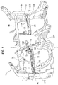
- FIG. 1 particularly shows a front structure of a cabin of a vehicle.
- FIG. 1 particularly shows a front structure of a cabin of a vehicle.
- only members related to the attachment structure of the knee-airbag device of the present invention in the cabin front structure are shown and illustration of the other members is omitted.
- an instrument panel member 2 is particularly arranged between right-and-left hinge pillars 1A, 1B which constitute a part of a vehicle body 1.
- the instrument panel member 2 is particularly made of a metal-made long member and arranged inside an instrument panel 4 (see FIGS. 2 and 3 ).
- the instrument panel member 2 is particularly attached to the left hinge pillar 1A at an end portion of its driver's-seat side portion 2A (its left-side portion in FIG. 1 ), and is attached to the right hinge pillar 1B at an end portion of its assistant-driver's-seat side portion 2B (its right-side portion in FIG. 1 ), whereby the instrument panel member 2 is provided to extend in a vehicle width direction between the both-side portions 1A, 1B of the vehicle body 1.
- the instrument panel member 2 is particularly configured such that the driver's-seat side portion 2A which requires the higher mechanical strength has a larger diameter than the assistant-driver's-seat side portion 2B.
- the driver's-seat side portion 2A is particularly configured such that a steering column, not illustrated, is attached to a central portion thereof.
- the instrument panel member 2 may be in any structure that is arranged between the hinge pillars 1A, 1B to support the instrument panel 4.
- the shape of the instrument panel member 2 is not limited to the elongated pile with a round-shaped cross-section as shown in the embodiment, but may have a rectangular cross-section or open cross-section.
- a floor panel 3 is particularly provided at a lower portion of the cabin and a tunnel portion 3A is particularly formed at a central portion, in the vehicle width direction, of the floor panel 3.
- a driver's seat and an assistant driver's seat, which are not illustrated, are particularly arranged on the floor panel 3 at positions located on right-and-left sides of the tunnel portion 3A.
- the knee-airbag devices 10, 20 are respectively arranged in front of the driver's seat and the assistant driver's seat at respective positions which correspond to knees of occupants seated in those seats.
- Each of the knee-airbag devices 10, 20 particularly includes an airbag inside thereof. This airbag is particularly configured to be inflated by an inflator when the accident occurs and expand accordingly, breaking an outer frame (case) of each of the knee-airbag devices 10, 20, for the protection of the occupant's knees.
- the driver's-seat side (left-side) knee-airbag device 10 is particularly attached to the left hinge pillar 1A of the vehicle body 1 via a vehicle-body side bracket 11 at its left-side end, and this driver's-seat side (left-side) knee-airbag device 10 is also attached particularly to an instrument-panel-member supporting post 13 via an instrument-panel-member supporting-post side bracket 12 at its right-side end.
- the assistant-driver's-seat side (right-side) knee-airbag device 20 is particularly attached to the right hinge pillar 1B of the vehicle body 1 via a vehicle-body side bracket 21 at its right-side end, and this assistant-driver's-seat side (right-side) knee-airbag device 20 is also attached particularly to the instrument panel member 2 via an instrument-panel-member side bracket 22 at its left-side end.
- Each of the knee-airbag devices 10, 20 is of a roughly rectangular solid shape and particularly provided to extend roughly horizontally in the vehicle width direction (in a lateral direction).
- the vehicle-body side brackets 11, 21 are particularly made of metal, for example, and these brackets 11, 21 respectively comprise knee-airbag side connection portions 11A, 21A which are connected to the knee-airbag devices 10, 20, vehicle-body side connection portions 11B, 21B which are connected to the hinge pillars 1A, 1B, and intermediate portions 11C, 21C which are particularly provided at respective middle positions between the knee-airbag side connection portions 11A, 21A and the vehicle-body side connection portions 11B, 21B.
- the intermediate portions 11C, 21C of the vehicle-body side brackets 11, 12 are particularly configured to extend roughly horizontally in the vehicle width direction from the knee-airbag devices 10, 20 toward the hinge pillars 1A, 1B.
- each length of these brackets 11, 21 can be properly short. That is, since the knee-airbag devices 10, 20 are particularly provided to extend in the vehicle width direction, each distance between the knee-airbag devices 10, 20 and the hinge pillars 1A, 1B is shorter than each distance between the knee-airbag devices 10, 20 and the instrument panel member 2, so that each length of these brackets 11, 21 can be properly short, compared to a case where the knee-airbag devices 10, 20 are connected to and supported at the instrument panel member 2.
- the intermediate portions 11C, 21C of the vehicle-body side brackets 11, 21 extend in the vehicle width direction and are particularly attached to respective portions of the hinge pillars 1A, 1B which are particularly positioned adjacently (the most closely), in the vehicle width direction, to the knee-airbag devices 11, 21, each length of the vehicle-body side brackets 11, 21 can be properly minimized.
- the weight increase can be properly suppressed because of the properly-short length of each of the vehicle-body side brackets 11, 21, so that securing of the high support rigidity and the weight saving can be compatibly attained for the attachment structure.
- the knee-airbag devices 10, 20 are respectively supported at the vehicle body 1 via the vehicle-body side brackets 11, 21, part of the inflation load of the knee airbags is dispersed to the vehicle body 1 having the large rigidity (the hinge pillars 1A, 1B ) by way of the vehicle-body side brackets 11, 21. Accordingly, the inflation load of the airbags can be properly supported at the vehicle body 1. Moreover, load dispersion to the instrument panel member 2 which supports various members (the instrument panel, the steering column, and the like) and need to bear excessive loads accordingly can be made properly small.
- Each of the intermediate portions 11C, 21C of the vehicle-body side brackets 11, 21 is particularly of a plate shape, and this plate-shaped plate face is particularly positioned substantially perpendicularly to the vehicle longitudinal direction (i.e., this plate-shaped plate face extends substantially in a vertical direction).
- this plate-shaped plate face extends substantially in a vertical direction.
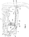
- FIGS. 2 through 5 particularly show the attachment structure of the assistant-driver's-seat side knee-airbag device 20.
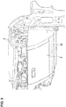
- a glove box 5 which constitutes a dashboard together with the instrument panel 4 is particularly arranged in front of the assistant driver's seat as shown in FIG. 3 , which is not illustrated in FIG. 1 .
- This glove box 5 is particularly positioned below the instrument panel 4.
- the knee-airbag device 20 is particularly arranged below the glove box 5.
- the instrument-panel-member side bracket 22 comprises a bracket body 22A and a branch bracket 22B which is configured to branch off from the bracket body 22A.
- the bracket body 22A is particularly fixed to a left end portion of the knee-airbag device 20 at its lower end, and connected to the assistant-driver's-seat side portion 2B of the instrument panel member 2 at its upper end.
- the branch bracket 22B is particularly configured to branch off from an intermittent part of the bracket body 22A and particularly extend obliquely rearwardly and downwardly, substantially in parallel to the bracket body 22A.
- the branch bracket 22B is particularly provided as a separate member from the bracket body 22A, and is particularly joined to the bracket body 22A via bolts 22C.
- the present invention is not limited to this structure, but the bracket body 22A and the branch bracket 22B may be formed as a single member.
- a lower end of the branch bracket 22B is fixed to an extension portion of an instrument panel core 4A which extends downwardly (which extends to a position beside the knee-airbag device 20 ).
- this instrument panel core 4A is a core part which forms a surface of the instrument panel 4 (which is another part than various devices/components), which is particularly made of resin having the high rigidity, for example.
- the knee-airbag device 20 is connected to and supported at both of the instrument panel member 2 and the instrument panel core 4A via the instrument-panel-member side bracket 22. Accordingly, the support rigidity can be increased compared to a case where the knee-airbag device is connected to the instrument panel member 2 only. Further, since only the branch bracket 22B is provided as an additional member, the weight increase of the attachment structure can be properly suppressed.
- the knee-airbag device 20 is supported by the vehicle-body side bracket 21 and the instrument-panel-member side bracket 22 such that the inflation direction of the knee airbag is particularly rearwardly-and-downwardly inclined.
- the knee airbag is particularly inflated such that it goes around an assistant-driver's-seat side surface of the glove box 5, and then extends along the surface of the glove box 5, so that the knee airbag is properly positioned between the glove box 5 and knee(s) of an occupant seated in the assistant driver's seat.
- the branch bracket 22B is configured to extend in the inflation direction of the knee airbag of the knee-airbag device 20 (in a rearwardly-and-downwardly oblique direction). Thereby, since supporting by means of the branch bracket 22B is attained along an input direction of the load during the knee-airbag inflation, the load of the knee-airbag inflation can be supported efficiently.
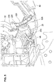
- one or more brackets are particularly provided at an upper face of the knee-airbag device 20.
- the heater-unit side bracket 23A which is arranged on the side of the instrument-panel-member side bracket 22 is particularly fixed to the upper face of the knee-airbag device 20, and the heater-unit side bracket 23B which is arranged on the side of the vehicle-body side bracket 21 is particularly provided integrally with the knee-airbag side connection portion 21A of the vehicle-body side bracket 21.
- the heater-unit side brackets 23A, 23B particularly extend vertically along a front side face of the knee-airbag device 20, then protrude forwardly, and are particularly connected to a lower panel 6A of the heater unit 6 which is arranged in front of the instrument panel 4. Thereby, since the knee-airbag device 20 is also fixed particularly to the heater unit 6 via the heater-unit side brackets 23A, 23B, the support rigidity can be further increased.
- the instrument-panel-member side bracket comprising the branch bracket
- the support structure positioned on an opposite side to the instrument-panel-member side bracket may be configured such that it is supported by the instrument panel member, not the vehicle-body side bracket, for example.
Landscapes
- Engineering & Computer Science (AREA)
- Mechanical Engineering (AREA)
- Chemical & Material Sciences (AREA)
- Combustion & Propulsion (AREA)
- Transportation (AREA)
- Air Bags (AREA)
- Body Structure For Vehicles (AREA)
Description
- The present invention relates to a vehicle and a method of arranging a knee-airbag-device for a vehicle.
- A knee-airbag device to protect a knee (knees) of an occupant when an accident occurs in a vehicle collision or the like has been used for a vehicle, such as an automotive vehicle. The knee-airbag device is arranged in front of a seat where an occupant is seated so that an airbag is inflatable toward the knee(s) of the occupant when the accident occurs.
- Japanese Patent Laid-Open Publication No.
2014-210548 2012-76531 - Herein, the knee-airbag device is required to inflate the airbag instantaneously (promptly) when the accident occurs, thereby protecting the occupant properly. Accordingly, since an attachment structure to support the knee-airbag device receives large impact during airbag inflation, it is needed that this attachment structure has the sufficiently large rigidity. However, if a support member of the attachment structure is configured to have a large plate thickness or a high-rigidity member is used as the support member of the attachment structure in order to increase the rigidity of the attachment structure, a vehicle weight so increases that the fuel economy (gas millage) of the vehicle or the like may deteriorate.
- The present invention has been devised in view of the above-described matter, and an object of the present invention is to secure the high support rigidity in the knee-airbag inflation, without increasing the weight.
- The present invention is a vehicle as defined in claim 1 and a method as defined in claim 8.
- According to the present invention, since the knee-airbag device is connected to and supported at both of the instrument panel member and the core part of the instrument panel (hereafter, referred to as an "instrument panel core"), the support rigidity can be properly increased compared to a case where the knee-airbag device is connected to the instrument panel member only. Further, since the branch bracket is provided only as an additional member, a weight increase of the attachment structure can be properly suppressed.
- In an embodiment of the present invention, the above-described knee-airbag-device attachment structure further comprises a vehicle-body side bracket connecting the vehicle body and the knee-airbag device.
- According to this structure, since the vehicle-body side bracket is the one for attaching the knee-airbag device to the vehicle body which is positioned relatively closely to the knee-airbag devices (a hinge pillar of the vehicle, example), a length of the vehicle-body side bracket can be made properly short. Accordingly, even if the plate thickness of the vehicle-body side bracket is made large or the rigidity of the vehicle-body side bracket is made high by using the high-rigidity member, the weight increase can be properly suppressed because of the properly-short length of the vehicle-body side bracket. Thereby, securing of the high support rigidity and the weight saving can be compatibly attained for the attachment structure. Further, since the knee-airbag device is supported at the vehicle body via the vehicle-body side bracket, part of a load which is caused by inflation of a knee airbag is dispersed to the vehicle body having the high rigidity by way of the vehicle-body side bracket. Thereby, the load of the knee-airbag inflation can be properly supported at the vehicle body.
- In the present invention, the branch bracket is configured to extend in a direction of inflation of a knee airbag of the knee-airbag device.
- According to this structure, since supporting by means of the branch bracket is attained along an input direction of the load during the knee-airbag inflation, the load of the knee-airbag inflation can be supported efficiently.
- In another embodiment of the present invention, the inflation direction of the knee airbag of the knee-airbag device is set to be rearwardly-and-downwardly inclined.
- According to this structure, since the knee airbag can be inflated along a surface of a glove box which is provided in front of a seat (assistant driver's seat), the inflated knee airbag can be positioned properly between the glove box and the knee(s) of the occupant.
- In another embodiment of the present invention, the vehicle-body side bracket is configured to have a plate-shaped portion partially at least, wherein the plate-shaped portion is configured such that a plate face thereof is positioned substantially perpendicularly to a vehicle longitudinal direction.
- According to this structure, the support rigidity of the vehicle-body side bracket along the direction of the knee-airbag inflation (an obliquely downward direction) can be increased properly.
- In another embodiment of the present invention, the knee-airbag-device attachment structure further comprises a heater-unit side bracket connecting the knee-airbag device and a lower panel of a heater unit.
- According to this structure, since the knee-airbag device is supported at the heater unit via the heater-unit side bracket, the support rigidity can be further increased.
- Other features, aspects, and advantages of the present invention will become apparent from the following description which refers to the accompanying drawings.
-
FIG. 1 is a perspective view showing a cabin front structure of a vehicle. -
FIG. 2 is a perspective view showing an attachment structure of a knee-airbag device of an embodiment of the present invention. -
FIG. 3 is a perspective view showing a structure which is positioned in front of an assistant driver's seat. -
FIG. 4 is a plan view showing the attachment structure of the knee-airbag device of the embodiment of the present invention. -
FIG. 5 is a perspective view showing the attachment structure of the knee-airbag device of the embodiment of the present invention. - Hereafter, an embodiment of the present invention will be described referring to the attached drawings.
-
FIG. 1 particularly shows a front structure of a cabin of a vehicle. In the drawings, only members related to the attachment structure of the knee-airbag device of the present invention in the cabin front structure are shown and illustration of the other members is omitted. - As shown in the figures, an instrument panel member 2 is particularly arranged between right-and-
left hinge pillars FIGS. 2 and3 ). The instrument panel member 2 is particularly attached to theleft hinge pillar 1A at an end portion of its driver's-seat side portion 2A (its left-side portion inFIG. 1 ), and is attached to theright hinge pillar 1B at an end portion of its assistant-driver's-seat side portion 2B (its right-side portion inFIG. 1 ), whereby the instrument panel member 2 is provided to extend in a vehicle width direction between the both-side portions - Herein, the instrument panel member 2 is particularly configured such that the driver's-
seat side portion 2A which requires the higher mechanical strength has a larger diameter than the assistant-driver's-seat side portion 2B. The driver's-seat side portion 2A is particularly configured such that a steering column, not illustrated, is attached to a central portion thereof. - The instrument panel member 2 may be in any structure that is arranged between the
hinge pillars instrument panel 4. For example, the shape of the instrument panel member 2 is not limited to the elongated pile with a round-shaped cross-section as shown in the embodiment, but may have a rectangular cross-section or open cross-section. - A
floor panel 3 is particularly provided at a lower portion of the cabin and atunnel portion 3A is particularly formed at a central portion, in the vehicle width direction, of thefloor panel 3. A driver's seat and an assistant driver's seat, which are not illustrated, are particularly arranged on thefloor panel 3 at positions located on right-and-left sides of thetunnel portion 3A. - The knee-
airbag devices airbag devices airbag devices - The driver's-seat side (left-side) knee-
airbag device 10 is particularly attached to theleft hinge pillar 1A of the vehicle body 1 via a vehicle-body side bracket 11 at its left-side end, and this driver's-seat side (left-side) knee-airbag device 10 is also attached particularly to an instrument-panel-member supporting post 13 via an instrument-panel-member supporting-post side bracket 12 at its right-side end. Meanwhile, the assistant-driver's-seat side (right-side) knee-airbag device 20 is particularly attached to theright hinge pillar 1B of the vehicle body 1 via a vehicle-body side bracket 21 at its right-side end, and this assistant-driver's-seat side (right-side) knee-airbag device 20 is also attached particularly to the instrument panel member 2 via an instrument-panel-member side bracket 22 at its left-side end. - Each of the knee-
airbag devices body side brackets brackets side connection portions airbag devices side connection portions hinge pillars intermediate portions 11C, 21C which are particularly provided at respective middle positions between the knee-airbagside connection portions side connection portions intermediate portions 11C, 21C of the vehicle-body side brackets airbag devices hinge pillars - Since the vehicle-
body side brackets hinge pillars brackets airbag devices airbag devices hinge pillars airbag devices brackets airbag devices intermediate portions 11C, 21C of the vehicle-body side brackets hinge pillars airbag devices body side brackets body side brackets body side brackets body side brackets - Further, since the knee-
airbag devices body side brackets hinge pillars body side brackets - Each of the
intermediate portions 11C, 21C of the vehicle-body side brackets body side brackets -
FIGS. 2 through 5 particularly show the attachment structure of the assistant-driver's-seat side knee-airbag device 20. Herein, aglove box 5 which constitutes a dashboard together with theinstrument panel 4 is particularly arranged in front of the assistant driver's seat as shown inFIG. 3 , which is not illustrated inFIG. 1 . Thisglove box 5 is particularly positioned below theinstrument panel 4. The knee-airbag device 20 is particularly arranged below theglove box 5. - As illustrated, the instrument-panel-
member side bracket 22 comprises abracket body 22A and abranch bracket 22B which is configured to branch off from thebracket body 22A. Thebracket body 22A is particularly fixed to a left end portion of the knee-airbag device 20 at its lower end, and connected to the assistant-driver's-seat side portion 2B of the instrument panel member 2 at its upper end. - The
branch bracket 22B is particularly configured to branch off from an intermittent part of thebracket body 22A and particularly extend obliquely rearwardly and downwardly, substantially in parallel to thebracket body 22A. In the present embodiment, thebranch bracket 22B is particularly provided as a separate member from thebracket body 22A, and is particularly joined to thebracket body 22A viabolts 22C. However, the present invention is not limited to this structure, but thebracket body 22A and thebranch bracket 22B may be formed as a single member. - A lower end of the
branch bracket 22B is fixed to an extension portion of aninstrument panel core 4A which extends downwardly (which extends to a position beside the knee-airbag device 20). Herein, thisinstrument panel core 4A is a core part which forms a surface of the instrument panel 4 (which is another part than various devices/components), which is particularly made of resin having the high rigidity, for example. - Thus, the knee-
airbag device 20 is connected to and supported at both of the instrument panel member 2 and theinstrument panel core 4A via the instrument-panel-member side bracket 22. Accordingly, the support rigidity can be increased compared to a case where the knee-airbag device is connected to the instrument panel member 2 only. Further, since only thebranch bracket 22B is provided as an additional member, the weight increase of the attachment structure can be properly suppressed. - The knee-
airbag device 20 is supported by the vehicle-body side bracket 21 and the instrument-panel-member side bracket 22 such that the inflation direction of the knee airbag is particularly rearwardly-and-downwardly inclined. Thereby, the knee airbag is particularly inflated such that it goes around an assistant-driver's-seat side surface of theglove box 5, and then extends along the surface of theglove box 5, so that the knee airbag is properly positioned between theglove box 5 and knee(s) of an occupant seated in the assistant driver's seat. - Further, the
branch bracket 22B is configured to extend in the inflation direction of the knee airbag of the knee-airbag device 20 (in a rearwardly-and-downwardly oblique direction). Thereby, since supporting by means of thebranch bracket 22B is attained along an input direction of the load during the knee-airbag inflation, the load of the knee-airbag inflation can be supported efficiently. - As shown in
FIGS. 4 and5 , one or more brackets, particularly a pair of right-and-left heater-unit side brackets airbag device 20. In the present embodiment, the heater-unit side bracket 23A which is arranged on the side of the instrument-panel-member side bracket 22 is particularly fixed to the upper face of the knee-airbag device 20, and the heater-unit side bracket 23B which is arranged on the side of the vehicle-body side bracket 21 is particularly provided integrally with the knee-airbagside connection portion 21A of the vehicle-body side bracket 21. - The heater-
unit side brackets airbag device 20, then protrude forwardly, and are particularly connected to alower panel 6A of theheater unit 6 which is arranged in front of theinstrument panel 4. Thereby, since the knee-airbag device 20 is also fixed particularly to theheater unit 6 via the heater-unit side brackets - For example, while the present invention (the instrument-panel-member side bracket comprising the branch bracket) is applied to an assistant-driver's-seat side structure in the above-described embodiment, it is applicable to a driver's-seat side structure. Further, the support structure positioned on an opposite side to the instrument-panel-member side bracket may be configured such that it is supported by the instrument panel member, not the vehicle-body side bracket, for example.
Claims (8)
- A vehicle comprising:an instrument panel (4);a knee-airbag device (20) configured to protect a knee of an occupant;an instrument panel member (2) extending in a vehicle width direction, attached to side faces of both sides of a vehicle body (1), and configured to support the instrument panel (4); andan instrument-panel-member side bracket (22) configured to connect the instrument panel member (2) and the knee-airbag device (20),characterized in thatsaid instrument-panel-member side bracket (22) comprises a bracket body (22A) and a branch bracket (22B) which is configured to branch off from the bracket body (22A) and connected to a core part (4A) of an instrument panel (4) of the vehicle,the core part (4A) is configured to form a surface of the instrument panel (4), andsaid branch bracket (22B) is configured to extend in a direction of inflation of a knee airbag of said knee-airbag device (20).
- The vehicle of claim 1, further comprising a vehicle-body side bracket (21) configured to connect the vehicle body (1) and said knee-airbag device (20).
- The vehicle of claim 1 or 2, wherein said inflation direction of the knee airbag of the knee-airbag device (20) is to be set to be rearwardly-and-downwardly inclined.
- The vehicle of any of the preceding claims, wherein said vehicle-body side bracket (21) is configured to have a plate-shaped portion (21C) at least partially.
- The vehicle of any of the preceding claims, wherein the plate-shaped portion (21C) is configured such that a plate face of the plate-shaped portion (21C) is positioned substantially perpendicularly to a vehicle longitudinal direction.
- The vehicle of any of the preceding claims, further comprising a heater-unit side bracket (23A, 23B) configured to connect said knee-airbag device (20) and a heater unit (6).
- The vehicle of any of the preceding claims, wherein the heater-unit side bracket (23A, 23B) configured to connect said knee-airbag device (20) and a lower panel (6A) of the heater unit (6).
- A method of arranging a knee-airbag-device for a vehicle, comprising
attaching an instrument panel member (2) extending in a vehicle width direction, to side faces of both sides of a vehicle body (1), wherein the instrument panel member (2) is configured to support an instrument panel (4) of a vehicle,
characterized by
connecting, by an instrument-panel-member side bracket (22), the instrument panel member (2) and a knee-airbag device (20) configured to protect a knee of an occupant,
wherein said instrument-panel-member side bracket (22) comprises a bracket body (22A) and a branch bracket (22B) which is configured to branch off from the bracket body (22A) and connected to a core part (4A) of the instrument panel (4) of the vehicle,
the core part (4A) is configured to form a surface of the instrument panel (4), and
said branch bracket (22B) is configured to extend in a direction of inflation of a knee airbag of said knee-airbag device (20).
Applications Claiming Priority (1)
| Application Number | Priority Date | Filing Date | Title |
|---|---|---|---|
| JP2018063735A JP7104892B2 (en) | 2018-03-29 | 2018-03-29 | Mounting structure for vehicle knee airbag device |
Publications (2)
| Publication Number | Publication Date |
|---|---|
| EP3546298A1 EP3546298A1 (en) | 2019-10-02 |
| EP3546298B1 true EP3546298B1 (en) | 2021-02-17 |
Family
ID=65576153
Family Applications (1)
| Application Number | Title | Priority Date | Filing Date |
|---|---|---|---|
| EP19158977.9A Active EP3546298B1 (en) | 2018-03-29 | 2019-02-25 | A vehicle and a method of arranging a knee-airbag-device |
Country Status (4)
| Country | Link |
|---|---|
| US (1) | US10829075B2 (en) |
| EP (1) | EP3546298B1 (en) |
| JP (1) | JP7104892B2 (en) |
| CN (1) | CN110316137B (en) |
Families Citing this family (3)
| Publication number | Priority date | Publication date | Assignee | Title |
|---|---|---|---|---|
| US11318993B1 (en) | 2020-10-13 | 2022-05-03 | Polestar Performance Ab | Modular cross car beam assembly |
| US11345402B2 (en) | 2020-10-13 | 2022-05-31 | Polestar Performance Ab | Cross car beam assembly with tapered joint |
| US11572105B2 (en) * | 2020-10-13 | 2023-02-07 | Polestar Performance Ab | Cross car beam assembly with integral safety unit |
Family Cites Families (34)
| Publication number | Priority date | Publication date | Assignee | Title |
|---|---|---|---|---|
| US5482319A (en) * | 1992-12-15 | 1996-01-09 | Mazda Motor Corporation | Passenger protection device for an automotive vehicle |
| US5934733A (en) * | 1997-12-19 | 1999-08-10 | General Motors Corporation | Extruded instrument panel structure |
| CA2355516C (en) * | 2001-08-17 | 2009-05-05 | Louis A. Nagy | Cross car support structure |
| DE10313730B4 (en) | 2003-03-27 | 2010-06-02 | GM Global Technology Operations, Inc., Detroit | Knee airbag module of a motor vehicle |
| EP1731410B1 (en) * | 2004-04-01 | 2009-10-21 | Calsonic Kansei Corporation | Steering support member structure |
| FR2871123B1 (en) * | 2004-06-02 | 2007-09-28 | Renault Sas | ARRANGEMENT FOR PROTECTING THE KNEES OF AN OCCUPANT OF A MOTOR VEHICLE AND DASHBOARD |
| US7832764B2 (en) * | 2005-05-10 | 2010-11-16 | Calsonic Kansei Corporation | Knee protector structure for vehicle |
| DE102006025384A1 (en) * | 2006-05-31 | 2007-12-06 | Siemens Ag | Motor vehicle e.g. car, cockpit, has sub-modules e.g. front-seat passenger sub module, self-supported to freely manage premounted components and to transfer dead weight of sub module and outer loads to cross bar in integrated condition |
| DE102007031406A1 (en) * | 2007-07-05 | 2009-01-08 | Dr. Ing. H.C. F. Porsche Aktiengesellschaft | Support for an airbag housing of a motor vehicle |
| US8100463B2 (en) * | 2008-01-09 | 2012-01-24 | Toyota Motor Engineering & Manufacturing North America, Inc. | Integrated brackets for vehicle instrument panels |
| JP2011207419A (en) | 2010-03-30 | 2011-10-20 | Toyota Motor Corp | Knee air bag device for vehicle |
| JP5494215B2 (en) | 2010-05-15 | 2014-05-14 | スズキ株式会社 | The lower structure of the instrument panel |
| JP5310689B2 (en) | 2010-09-30 | 2013-10-09 | トヨタ自動車株式会社 | Vehicle occupant knee protection device |
| DE102011051699B4 (en) * | 2011-07-08 | 2026-05-07 | Dr. Ing. H.C. F. Porsche Aktiengesellschaft | motor vehicle |
| CA2866630C (en) * | 2012-03-30 | 2019-04-16 | Magna International Inc. | Plastic overmolding of aluminum extrusions |
| KR101637207B1 (en) * | 2012-11-29 | 2016-07-08 | 아우토리브 디벨롭먼트 아베 | Safety apparaus for vehicle |
| KR101614496B1 (en) * | 2013-04-08 | 2016-05-02 | 아우토리브 디벨롭먼트 아베 | Airbag for knee airbag apparatus |
| JP5786886B2 (en) | 2013-04-19 | 2015-09-30 | トヨタ自動車株式会社 | Car cabin front structure |
| DE102013016133B4 (en) * | 2013-09-27 | 2015-08-06 | Audi Ag | Instrument panel cross member for a vehicle and vehicle with such an instrument panel cross member |
| US9446800B2 (en) * | 2014-05-30 | 2016-09-20 | Van-Rob Inc. | Vehicle cross-support member with hybrid metal joint |
| JP2016060323A (en) * | 2014-09-17 | 2016-04-25 | 日産自動車株式会社 | Passenger protection apparatus |
| US9669788B2 (en) * | 2014-10-03 | 2017-06-06 | GM Global Technology Operations LLC | Knee airbag for motor vehicle |
| SE540950C2 (en) * | 2015-04-17 | 2019-01-08 | Ningbo Geely Automobile Res & Development Co Ltd | Energy-absorbing knee bolster frame for a vehicle |
| DE102015119229B4 (en) * | 2015-11-09 | 2020-04-23 | Benteler Automobiltechnik Gmbh | Instrument holder for holding an attachment in a motor vehicle |
| JP2017144895A (en) * | 2016-02-17 | 2017-08-24 | カルソニックカンセイ株式会社 | Steering member and method for manufacturing the same |
| US9580107B1 (en) * | 2016-04-26 | 2017-02-28 | Dura Operating, Llc | Modular hybrid cross car beam assembly |
| EP3494030A1 (en) * | 2016-08-03 | 2019-06-12 | SABIC Global Technologies B.V. | Vehicle cross members and related methods |
| US10457240B2 (en) * | 2016-11-04 | 2019-10-29 | Magnesium Products Of America | Glove box rail with integrated airbag support |
| FR3059971B1 (en) * | 2016-12-09 | 2020-01-03 | Renault S.A.S | DIRECT SIMPLIFIED ATTACHMENT OF A VEHICLE DRIVER CROSSBODY BRAKE. |
| JP6852669B2 (en) * | 2017-12-28 | 2021-03-31 | 豊田合成株式会社 | Knee protection airbag device |
| JP7245444B2 (en) * | 2018-03-29 | 2023-03-24 | マツダ株式会社 | Mounting structure for vehicle knee airbag device |
| KR102533288B1 (en) * | 2018-06-20 | 2023-05-17 | 현대모비스 주식회사 | Mounting structure of knee airbag apparatus for vehicle |
| WO2020096692A2 (en) * | 2018-09-05 | 2020-05-14 | Magnesium Products of America, Inc. | Cross-car beam structure with pencil brace for cowl attachment |
| KR102552168B1 (en) * | 2018-12-13 | 2023-07-05 | 현대자동차주식회사 | Light Weight Cowl cross bar for vehicle |
-
2018
- 2018-03-29 JP JP2018063735A patent/JP7104892B2/en active Active
-
2019
- 2019-02-19 CN CN201910124501.3A patent/CN110316137B/en active Active
- 2019-02-25 EP EP19158977.9A patent/EP3546298B1/en active Active
- 2019-03-06 US US16/294,532 patent/US10829075B2/en active Active
Non-Patent Citations (1)
| Title |
|---|
| None * |
Also Published As
| Publication number | Publication date |
|---|---|
| US10829075B2 (en) | 2020-11-10 |
| CN110316137B (en) | 2021-10-22 |
| JP7104892B2 (en) | 2022-07-22 |
| CN110316137A (en) | 2019-10-11 |
| US20190299900A1 (en) | 2019-10-03 |
| EP3546298A1 (en) | 2019-10-02 |
| JP2019172116A (en) | 2019-10-10 |
Similar Documents
| Publication | Publication Date | Title |
|---|---|---|
| KR101730998B1 (en) | Cabin front structure of automobile | |
| EP3446931B1 (en) | Passenger protection device for front passenger seat | |
| KR20090108700A (en) | Airbags, Airbag Modules and Vehicles | |
| KR101637207B1 (en) | Safety apparaus for vehicle | |
| EP3546298B1 (en) | A vehicle and a method of arranging a knee-airbag-device | |
| JP2011207419A (en) | Knee air bag device for vehicle | |
| EP3546299B1 (en) | Knee-airbag-device attachment structure for a vehicle, a protection system, a vehicle, and a method of arranging a knee-airbag-device | |
| US20130186230A1 (en) | Rearward pedal movement restraint assembly for vehicle | |
| CN101190676B (en) | Instrument board supporting framework | |
| JP2015016718A (en) | Car cabin front structure | |
| JP7096996B2 (en) | Mounting structure of vehicle knee airbag device | |
| KR20090019261A (en) | Mounting structure of the airbag module | |
| JP2019031132A (en) | Vehicle seat | |
| JP5229260B2 (en) | Knee airbag device for vehicle | |
| JP4628813B2 (en) | Vehicle front structure | |
| JP2019031133A (en) | Vehicle seat | |
| EP3375671B1 (en) | Airbag system for a vehicle | |
| JP2022155951A (en) | Instrument panel mounting structure | |
| JP2021020530A (en) | Vehicular knee airbag device | |
| KR19990010907A (en) | Front floor panel structure of vehicle with reinforcement structure | |
| KR19980032905U (en) | Side collision reinforcement structure of automobile |
Legal Events
| Date | Code | Title | Description |
|---|---|---|---|
| PUAI | Public reference made under article 153(3) epc to a published international application that has entered the european phase |
Free format text: ORIGINAL CODE: 0009012 |
|
| STAA | Information on the status of an ep patent application or granted ep patent |
Free format text: STATUS: THE APPLICATION HAS BEEN PUBLISHED |
|
| AK | Designated contracting states |
Kind code of ref document: A1 Designated state(s): AL AT BE BG CH CY CZ DE DK EE ES FI FR GB GR HR HU IE IS IT LI LT LU LV MC MK MT NL NO PL PT RO RS SE SI SK SM TR |
|
| AX | Request for extension of the european patent |
Extension state: BA ME |
|
| STAA | Information on the status of an ep patent application or granted ep patent |
Free format text: STATUS: REQUEST FOR EXAMINATION WAS MADE |
|
| 17P | Request for examination filed |
Effective date: 20200331 |
|
| RBV | Designated contracting states (corrected) |
Designated state(s): AL AT BE BG CH CY CZ DE DK EE ES FI FR GB GR HR HU IE IS IT LI LT LU LV MC MK MT NL NO PL PT RO RS SE SI SK SM TR |
|
| GRAP | Despatch of communication of intention to grant a patent |
Free format text: ORIGINAL CODE: EPIDOSNIGR1 |
|
| RIC1 | Information provided on ipc code assigned before grant |
Ipc: B62D 25/14 20060101ALI20200827BHEP Ipc: B62D 1/16 20060101ALI20200827BHEP Ipc: B60R 21/206 20110101AFI20200827BHEP |
|
| STAA | Information on the status of an ep patent application or granted ep patent |
Free format text: STATUS: GRANT OF PATENT IS INTENDED |
|
| INTG | Intention to grant announced |
Effective date: 20201001 |
|
| GRAS | Grant fee paid |
Free format text: ORIGINAL CODE: EPIDOSNIGR3 |
|
| GRAA | (expected) grant |
Free format text: ORIGINAL CODE: 0009210 |
|
| STAA | Information on the status of an ep patent application or granted ep patent |
Free format text: STATUS: THE PATENT HAS BEEN GRANTED |
|
| AK | Designated contracting states |
Kind code of ref document: B1 Designated state(s): AL AT BE BG CH CY CZ DE DK EE ES FI FR GB GR HR HU IE IS IT LI LT LU LV MC MK MT NL NO PL PT RO RS SE SI SK SM TR |
|
| REG | Reference to a national code |
Ref country code: GB Ref legal event code: FG4D |
|
| REG | Reference to a national code |
Ref country code: CH Ref legal event code: EP |
|
| REG | Reference to a national code |
Ref country code: DE Ref legal event code: R096 Ref document number: 602019002437 Country of ref document: DE |
|
| REG | Reference to a national code |
Ref country code: AT Ref legal event code: REF Ref document number: 1361076 Country of ref document: AT Kind code of ref document: T Effective date: 20210315 |
|
| REG | Reference to a national code |
Ref country code: IE Ref legal event code: FG4D |
|
| REG | Reference to a national code |
Ref country code: LT Ref legal event code: MG9D |
|
| REG | Reference to a national code |
Ref country code: NL Ref legal event code: MP Effective date: 20210217 |
|
| PG25 | Lapsed in a contracting state [announced via postgrant information from national office to epo] |
Ref country code: GR Free format text: LAPSE BECAUSE OF FAILURE TO SUBMIT A TRANSLATION OF THE DESCRIPTION OR TO PAY THE FEE WITHIN THE PRESCRIBED TIME-LIMIT Effective date: 20210518 Ref country code: FI Free format text: LAPSE BECAUSE OF FAILURE TO SUBMIT A TRANSLATION OF THE DESCRIPTION OR TO PAY THE FEE WITHIN THE PRESCRIBED TIME-LIMIT Effective date: 20210217 Ref country code: HR Free format text: LAPSE BECAUSE OF FAILURE TO SUBMIT A TRANSLATION OF THE DESCRIPTION OR TO PAY THE FEE WITHIN THE PRESCRIBED TIME-LIMIT Effective date: 20210217 Ref country code: BG Free format text: LAPSE BECAUSE OF FAILURE TO SUBMIT A TRANSLATION OF THE DESCRIPTION OR TO PAY THE FEE WITHIN THE PRESCRIBED TIME-LIMIT Effective date: 20210517 Ref country code: LT Free format text: LAPSE BECAUSE OF FAILURE TO SUBMIT A TRANSLATION OF THE DESCRIPTION OR TO PAY THE FEE WITHIN THE PRESCRIBED TIME-LIMIT Effective date: 20210217 Ref country code: PT Free format text: LAPSE BECAUSE OF FAILURE TO SUBMIT A TRANSLATION OF THE DESCRIPTION OR TO PAY THE FEE WITHIN THE PRESCRIBED TIME-LIMIT Effective date: 20210617 Ref country code: NO Free format text: LAPSE BECAUSE OF FAILURE TO SUBMIT A TRANSLATION OF THE DESCRIPTION OR TO PAY THE FEE WITHIN THE PRESCRIBED TIME-LIMIT Effective date: 20210517 |
|
| REG | Reference to a national code |
Ref country code: AT Ref legal event code: MK05 Ref document number: 1361076 Country of ref document: AT Kind code of ref document: T Effective date: 20210217 |
|
| PG25 | Lapsed in a contracting state [announced via postgrant information from national office to epo] |
Ref country code: SE Free format text: LAPSE BECAUSE OF FAILURE TO SUBMIT A TRANSLATION OF THE DESCRIPTION OR TO PAY THE FEE WITHIN THE PRESCRIBED TIME-LIMIT Effective date: 20210217 Ref country code: RS Free format text: LAPSE BECAUSE OF FAILURE TO SUBMIT A TRANSLATION OF THE DESCRIPTION OR TO PAY THE FEE WITHIN THE PRESCRIBED TIME-LIMIT Effective date: 20210217 Ref country code: LV Free format text: LAPSE BECAUSE OF FAILURE TO SUBMIT A TRANSLATION OF THE DESCRIPTION OR TO PAY THE FEE WITHIN THE PRESCRIBED TIME-LIMIT Effective date: 20210217 Ref country code: PL Free format text: LAPSE BECAUSE OF FAILURE TO SUBMIT A TRANSLATION OF THE DESCRIPTION OR TO PAY THE FEE WITHIN THE PRESCRIBED TIME-LIMIT Effective date: 20210217 Ref country code: NL Free format text: LAPSE BECAUSE OF FAILURE TO SUBMIT A TRANSLATION OF THE DESCRIPTION OR TO PAY THE FEE WITHIN THE PRESCRIBED TIME-LIMIT Effective date: 20210217 |
|
| PG25 | Lapsed in a contracting state [announced via postgrant information from national office to epo] |
Ref country code: IS Free format text: LAPSE BECAUSE OF FAILURE TO SUBMIT A TRANSLATION OF THE DESCRIPTION OR TO PAY THE FEE WITHIN THE PRESCRIBED TIME-LIMIT Effective date: 20210617 |
|
| REG | Reference to a national code |
Ref country code: BE Ref legal event code: MM Effective date: 20210228 |
|
| PG25 | Lapsed in a contracting state [announced via postgrant information from national office to epo] |
Ref country code: SM Free format text: LAPSE BECAUSE OF FAILURE TO SUBMIT A TRANSLATION OF THE DESCRIPTION OR TO PAY THE FEE WITHIN THE PRESCRIBED TIME-LIMIT Effective date: 20210217 Ref country code: AT Free format text: LAPSE BECAUSE OF FAILURE TO SUBMIT A TRANSLATION OF THE DESCRIPTION OR TO PAY THE FEE WITHIN THE PRESCRIBED TIME-LIMIT Effective date: 20210217 Ref country code: LU Free format text: LAPSE BECAUSE OF NON-PAYMENT OF DUE FEES Effective date: 20210225 Ref country code: EE Free format text: LAPSE BECAUSE OF FAILURE TO SUBMIT A TRANSLATION OF THE DESCRIPTION OR TO PAY THE FEE WITHIN THE PRESCRIBED TIME-LIMIT Effective date: 20210217 Ref country code: CZ Free format text: LAPSE BECAUSE OF FAILURE TO SUBMIT A TRANSLATION OF THE DESCRIPTION OR TO PAY THE FEE WITHIN THE PRESCRIBED TIME-LIMIT Effective date: 20210217 |
|
| REG | Reference to a national code |
Ref country code: DE Ref legal event code: R097 Ref document number: 602019002437 Country of ref document: DE |
|
| PG25 | Lapsed in a contracting state [announced via postgrant information from national office to epo] |
Ref country code: DK Free format text: LAPSE BECAUSE OF FAILURE TO SUBMIT A TRANSLATION OF THE DESCRIPTION OR TO PAY THE FEE WITHIN THE PRESCRIBED TIME-LIMIT Effective date: 20210217 Ref country code: SK Free format text: LAPSE BECAUSE OF FAILURE TO SUBMIT A TRANSLATION OF THE DESCRIPTION OR TO PAY THE FEE WITHIN THE PRESCRIBED TIME-LIMIT Effective date: 20210217 Ref country code: RO Free format text: LAPSE BECAUSE OF FAILURE TO SUBMIT A TRANSLATION OF THE DESCRIPTION OR TO PAY THE FEE WITHIN THE PRESCRIBED TIME-LIMIT Effective date: 20210217 Ref country code: MC Free format text: LAPSE BECAUSE OF FAILURE TO SUBMIT A TRANSLATION OF THE DESCRIPTION OR TO PAY THE FEE WITHIN THE PRESCRIBED TIME-LIMIT Effective date: 20210217 |
|
| PLBE | No opposition filed within time limit |
Free format text: ORIGINAL CODE: 0009261 |
|
| STAA | Information on the status of an ep patent application or granted ep patent |
Free format text: STATUS: NO OPPOSITION FILED WITHIN TIME LIMIT |
|
| 26N | No opposition filed |
Effective date: 20211118 |
|
| PG25 | Lapsed in a contracting state [announced via postgrant information from national office to epo] |
Ref country code: ES Free format text: LAPSE BECAUSE OF FAILURE TO SUBMIT A TRANSLATION OF THE DESCRIPTION OR TO PAY THE FEE WITHIN THE PRESCRIBED TIME-LIMIT Effective date: 20210217 Ref country code: FR Free format text: LAPSE BECAUSE OF NON-PAYMENT OF DUE FEES Effective date: 20210417 Ref country code: IE Free format text: LAPSE BECAUSE OF NON-PAYMENT OF DUE FEES Effective date: 20210225 Ref country code: AL Free format text: LAPSE BECAUSE OF FAILURE TO SUBMIT A TRANSLATION OF THE DESCRIPTION OR TO PAY THE FEE WITHIN THE PRESCRIBED TIME-LIMIT Effective date: 20210217 |
|
| PG25 | Lapsed in a contracting state [announced via postgrant information from national office to epo] |
Ref country code: SI Free format text: LAPSE BECAUSE OF FAILURE TO SUBMIT A TRANSLATION OF THE DESCRIPTION OR TO PAY THE FEE WITHIN THE PRESCRIBED TIME-LIMIT Effective date: 20210217 |
|
| PG25 | Lapsed in a contracting state [announced via postgrant information from national office to epo] |
Ref country code: IT Free format text: LAPSE BECAUSE OF FAILURE TO SUBMIT A TRANSLATION OF THE DESCRIPTION OR TO PAY THE FEE WITHIN THE PRESCRIBED TIME-LIMIT Effective date: 20210217 |
|
| PG25 | Lapsed in a contracting state [announced via postgrant information from national office to epo] |
Ref country code: IS Free format text: LAPSE BECAUSE OF FAILURE TO SUBMIT A TRANSLATION OF THE DESCRIPTION OR TO PAY THE FEE WITHIN THE PRESCRIBED TIME-LIMIT Effective date: 20210617 |
|
| PG25 | Lapsed in a contracting state [announced via postgrant information from national office to epo] |
Ref country code: BE Free format text: LAPSE BECAUSE OF NON-PAYMENT OF DUE FEES Effective date: 20210228 |
|
| REG | Reference to a national code |
Ref country code: CH Ref legal event code: PL |
|
| PG25 | Lapsed in a contracting state [announced via postgrant information from national office to epo] |
Ref country code: LI Free format text: LAPSE BECAUSE OF NON-PAYMENT OF DUE FEES Effective date: 20220228 Ref country code: CH Free format text: LAPSE BECAUSE OF NON-PAYMENT OF DUE FEES Effective date: 20220228 |
|
| PG25 | Lapsed in a contracting state [announced via postgrant information from national office to epo] |
Ref country code: CY Free format text: LAPSE BECAUSE OF FAILURE TO SUBMIT A TRANSLATION OF THE DESCRIPTION OR TO PAY THE FEE WITHIN THE PRESCRIBED TIME-LIMIT Effective date: 20210217 |
|
| PG25 | Lapsed in a contracting state [announced via postgrant information from national office to epo] |
Ref country code: HU Free format text: LAPSE BECAUSE OF FAILURE TO SUBMIT A TRANSLATION OF THE DESCRIPTION OR TO PAY THE FEE WITHIN THE PRESCRIBED TIME-LIMIT; INVALID AB INITIO Effective date: 20190225 |
|
| GBPC | Gb: european patent ceased through non-payment of renewal fee |
Effective date: 20230225 |
|
| PG25 | Lapsed in a contracting state [announced via postgrant information from national office to epo] |
Ref country code: GB Free format text: LAPSE BECAUSE OF NON-PAYMENT OF DUE FEES Effective date: 20230225 |
|
| PG25 | Lapsed in a contracting state [announced via postgrant information from national office to epo] |
Ref country code: GB Free format text: LAPSE BECAUSE OF NON-PAYMENT OF DUE FEES Effective date: 20230225 |
|
| PG25 | Lapsed in a contracting state [announced via postgrant information from national office to epo] |
Ref country code: MK Free format text: LAPSE BECAUSE OF FAILURE TO SUBMIT A TRANSLATION OF THE DESCRIPTION OR TO PAY THE FEE WITHIN THE PRESCRIBED TIME-LIMIT Effective date: 20210217 |
|
| PG25 | Lapsed in a contracting state [announced via postgrant information from national office to epo] |
Ref country code: MT Free format text: LAPSE BECAUSE OF FAILURE TO SUBMIT A TRANSLATION OF THE DESCRIPTION OR TO PAY THE FEE WITHIN THE PRESCRIBED TIME-LIMIT Effective date: 20210217 |
|
| PG25 | Lapsed in a contracting state [announced via postgrant information from national office to epo] |
Ref country code: TR Free format text: LAPSE BECAUSE OF FAILURE TO SUBMIT A TRANSLATION OF THE DESCRIPTION OR TO PAY THE FEE WITHIN THE PRESCRIBED TIME-LIMIT Effective date: 20210217 |
|
| PGFP | Annual fee paid to national office [announced via postgrant information from national office to epo] |
Ref country code: DE Payment date: 20260102 Year of fee payment: 8 |