EP3546137A1 - Robot system and method for controlling robot - Google Patents
Robot system and method for controlling robot Download PDFInfo
- Publication number
- EP3546137A1 EP3546137A1 EP19163085.4A EP19163085A EP3546137A1 EP 3546137 A1 EP3546137 A1 EP 3546137A1 EP 19163085 A EP19163085 A EP 19163085A EP 3546137 A1 EP3546137 A1 EP 3546137A1
- Authority
- EP
- European Patent Office
- Prior art keywords
- leading end
- controller
- posture
- control
- robot
- Prior art date
- Legal status (The legal status is an assumption and is not a legal conclusion. Google has not performed a legal analysis and makes no representation as to the accuracy of the status listed.)
- Granted
Links
Images






Classifications
-
- B—PERFORMING OPERATIONS; TRANSPORTING
- B25—HAND TOOLS; PORTABLE POWER-DRIVEN TOOLS; MANIPULATORS
- B25J—MANIPULATORS; CHAMBERS PROVIDED WITH MANIPULATION DEVICES
- B25J9/00—Program-controlled manipulators
- B25J9/10—Program-controlled manipulators characterised by positioning means for manipulator elements
- B25J9/1005—Program-controlled manipulators characterised by positioning means for manipulator elements comprising adjusting means
-
- B—PERFORMING OPERATIONS; TRANSPORTING
- B25—HAND TOOLS; PORTABLE POWER-DRIVEN TOOLS; MANIPULATORS
- B25J—MANIPULATORS; CHAMBERS PROVIDED WITH MANIPULATION DEVICES
- B25J9/00—Program-controlled manipulators
- B25J9/16—Program controls
- B25J9/1628—Program controls characterised by the control loop
- B25J9/1633—Program controls characterised by the control loop compliant, force, torque control, e.g. combined with position control
-
- B—PERFORMING OPERATIONS; TRANSPORTING
- B25—HAND TOOLS; PORTABLE POWER-DRIVEN TOOLS; MANIPULATORS
- B25J—MANIPULATORS; CHAMBERS PROVIDED WITH MANIPULATION DEVICES
- B25J13/00—Controls for manipulators
- B25J13/003—Controls for manipulators by means of an audio-responsive input
-
- B—PERFORMING OPERATIONS; TRANSPORTING
- B25—HAND TOOLS; PORTABLE POWER-DRIVEN TOOLS; MANIPULATORS
- B25J—MANIPULATORS; CHAMBERS PROVIDED WITH MANIPULATION DEVICES
- B25J9/00—Program-controlled manipulators
- B25J9/06—Program-controlled manipulators characterised by multi-articulated arms
-
- B—PERFORMING OPERATIONS; TRANSPORTING
- B25—HAND TOOLS; PORTABLE POWER-DRIVEN TOOLS; MANIPULATORS
- B25J—MANIPULATORS; CHAMBERS PROVIDED WITH MANIPULATION DEVICES
- B25J9/00—Program-controlled manipulators
- B25J9/16—Program controls
- B25J9/1612—Program controls characterised by the hand, wrist, grip control
-
- B—PERFORMING OPERATIONS; TRANSPORTING
- B25—HAND TOOLS; PORTABLE POWER-DRIVEN TOOLS; MANIPULATORS
- B25J—MANIPULATORS; CHAMBERS PROVIDED WITH MANIPULATION DEVICES
- B25J9/00—Program-controlled manipulators
- B25J9/16—Program controls
- B25J9/1656—Program controls characterised by programming, planning systems for manipulators
-
- G—PHYSICS
- G05—CONTROLLING; REGULATING
- G05B—CONTROL OR REGULATING SYSTEMS IN GENERAL; FUNCTIONAL ELEMENTS OF SUCH SYSTEMS; MONITORING OR TESTING ARRANGEMENTS FOR SUCH SYSTEMS OR ELEMENTS
- G05B19/00—Program-control systems
- G05B19/02—Program-control systems electric
- G05B19/42—Recording and playback systems, i.e. in which the program is recorded from a cycle of operations, e.g. the cycle of operations being manually controlled, after which this record is played back on the same machine
- G05B19/423—Teaching successive positions by walk-through, i.e. the tool head or end effector being grasped and guided directly, with or without servo-assistance, to follow a path
-
- G—PHYSICS
- G05—CONTROLLING; REGULATING
- G05B—CONTROL OR REGULATING SYSTEMS IN GENERAL; FUNCTIONAL ELEMENTS OF SUCH SYSTEMS; MONITORING OR TESTING ARRANGEMENTS FOR SUCH SYSTEMS OR ELEMENTS
- G05B2219/00—Program-control systems
- G05B2219/30—Nc systems
- G05B2219/37—Measurements
- G05B2219/37411—Measure contact from force and velocity detection
-
- G—PHYSICS
- G05—CONTROLLING; REGULATING
- G05B—CONTROL OR REGULATING SYSTEMS IN GENERAL; FUNCTIONAL ELEMENTS OF SUCH SYSTEMS; MONITORING OR TESTING ARRANGEMENTS FOR SUCH SYSTEMS OR ELEMENTS
- G05B2219/00—Program-control systems
- G05B2219/30—Nc systems
- G05B2219/39—Robotics, robotics to robotics hand
- G05B2219/39295—Learn position correction values to be added to reference values
-
- G—PHYSICS
- G05—CONTROLLING; REGULATING
- G05B—CONTROL OR REGULATING SYSTEMS IN GENERAL; FUNCTIONAL ELEMENTS OF SUCH SYSTEMS; MONITORING OR TESTING ARRANGEMENTS FOR SUCH SYSTEMS OR ELEMENTS
- G05B2219/00—Program-control systems
- G05B2219/30—Nc systems
- G05B2219/39—Robotics, robotics to robotics hand
- G05B2219/39319—Force control, force as reference, active compliance
-
- G—PHYSICS
- G05—CONTROLLING; REGULATING
- G05B—CONTROL OR REGULATING SYSTEMS IN GENERAL; FUNCTIONAL ELEMENTS OF SUCH SYSTEMS; MONITORING OR TESTING ARRANGEMENTS FOR SUCH SYSTEMS OR ELEMENTS
- G05B2219/00—Program-control systems
- G05B2219/30—Nc systems
- G05B2219/39—Robotics, robotics to robotics hand
- G05B2219/39343—Force based impedance control
-
- G—PHYSICS
- G05—CONTROLLING; REGULATING
- G05B—CONTROL OR REGULATING SYSTEMS IN GENERAL; FUNCTIONAL ELEMENTS OF SUCH SYSTEMS; MONITORING OR TESTING ARRANGEMENTS FOR SUCH SYSTEMS OR ELEMENTS
- G05B2219/00—Program-control systems
- G05B2219/30—Nc systems
- G05B2219/40—Robotics, robotics mapping to robotics vision
- G05B2219/40201—Detect contact, collision with human
-
- G—PHYSICS
- G05—CONTROLLING; REGULATING
- G05B—CONTROL OR REGULATING SYSTEMS IN GENERAL; FUNCTIONAL ELEMENTS OF SUCH SYSTEMS; MONITORING OR TESTING ARRANGEMENTS FOR SUCH SYSTEMS OR ELEMENTS
- G05B2219/00—Program-control systems
- G05B2219/30—Nc systems
- G05B2219/40—Robotics, robotics mapping to robotics vision
- G05B2219/40202—Human robot coexistence
-
- G—PHYSICS
- G05—CONTROLLING; REGULATING
- G05B—CONTROL OR REGULATING SYSTEMS IN GENERAL; FUNCTIONAL ELEMENTS OF SUCH SYSTEMS; MONITORING OR TESTING ARRANGEMENTS FOR SUCH SYSTEMS OR ELEMENTS
- G05B2219/00—Program-control systems
- G05B2219/30—Nc systems
- G05B2219/40—Robotics, robotics mapping to robotics vision
- G05B2219/40385—Compare offline teached point with online teached point, modify rest as function of error
Definitions
- the present invention relates to a robot system and a method for controlling a robot.
- JP 2006-82185A discloses a method for guiding a robot.
- the method includes: a first step in which the robot stops during a reproduction motion that is based on a work program registered in advance; a second step of permitting direct manipulation of the robot; a third step of directly manipulating the robot to make a guided motion; a fourth step of prohibiting the direct manipulation of the robot; and a fifth step in which the robot continues the reproduction motion based on the work program. If, at the third step, any teaching point is modified in position, the motion of the robot at the fifth step is a motion equivalent to linear interpolation between the modified teaching point and the next, unmodified teaching point.
- JP 2006-82185A The contents of JP 2006-82185A are incorporated herein by reference in their entirety.
- a robot system includes a robot, a normal controller, a force guide controller, a relative information obtainer, and a correction controller.
- the robot includes a leading end, a base, and a multi-articular arm.
- the multi-articular arm is configured to adjust a position and a posture of the leading end relative to the base.
- the normal controller is configured to control the multi-articular arm to move the leading end based on a motion program that specifies a transition over time of a target position and a target posture of the leading end relative to the base.
- the transition includes a correction target section that starts and ends in the transition.
- the force guide controller is configured to control the multi-articular arm to move the leading end in response to a guide manipulation of applying an external force to the robot while the normal controller is controlling the multi-articular arm.
- the relative information obtainer is configured to obtain relative command information that is based on the target position and the target posture of the leading end at a start point of the correction target section and that specifies the target position and the target posture of the leading end at points of the correction target section including the start point and an end point of the correction target section.
- the correction controller is configured to control the multi-articular arm to, based on the relative command information, move the leading end from the position and the posture of the leading end as of a point of time when movement of the multi-articular arm controlled by the force guide controller ended.
- a method is for controlling a robot.
- the robot includes a leading end, a base, and a multi-articular arm.
- the multi-articular arm is configured to adjust a position and a posture of the leading end relative to the base.
- the method includes performing normal control that includes controlling the multi-articular arm to move the leading end based on a motion program that specifies a transition over time of a target position and a target posture of the leading end relative to the base.
- the transition includes a correction target section that starts and ends in the transition.
- Force guide control is performed that includes controlling the multi-articular arm to move the leading end in response to a guide manipulation of applying an external force to the robot during the normal control.
- Relative command information is obtained that specifies the target position and the target posture of the leading end at a start point through to an end point of the correction target section.
- Correction control is performed that includes controlling the multi-articular arm to, based on the relative command information, move the leading end from the position and the posture of the leading end as of a point of time when movement of the multi-articular arm controlled by the force guide controller ended.
- the present invention provides a robot system that is effective for saving labor of a human being in cooperative work performed by the human being and a robot.
- a robot system 1 is a human cooperative system, in which a robot 2 and a worker cooperate with each other.
- the robot system 1 includes the robot 2 and a controller 100.
- the robot 2 is a six-axis vertical multi-articular robot, and includes a base 3, a leading end 4, a multi-articular arm 10, a tool 5, and an input switch 6.
- the base 3 is disposed on the floor of a workspace of the robot 2.
- the multi-articular arm 10 connects the base 3 and the leading end 4 to each other.
- the multi-articular arm 10 includes a plurality of joints, and adjusts the position and the posture of the leading end 4 relative to the base 3 by changing the angles of the plurality of joints.
- the multi-articular arm 10 includes a turnable part 11, a lower arm 12, an upper arm 13, a wrist 16, actuators 21, 22, 23, 24, 25, and 26, and force sensors 31, 32, 33, 34, 35, and 36.
- the turnable part 11 is located at an upper part of the base 3 turnably about vertical axis Ax1.
- the multi-articular arm 10 includes a joint 41.
- the joint 41 makes the turnable part 11 turnable about the vertical axis Ax1.
- the lower arm 12 is connected to the lower arm 12 swingably about axis Ax2, which crosses (for example, is orthogonal to) the vertical axis Ax1.
- the multi-articular arm 10 includes a joint 42.
- the joint 42 makes the lower arm 12 swingable about the axis Ax2.
- the upper arm 13 is connected to an end of the lower arm 12 swingably about axis Ax3, which crosses the vertical axis Ax1.
- the multi-articular arm 10 includes a joint 43.
- the joint 43 makes the upper arm 13 swingable the axis Ax3.
- the axis Ax3 may be parallel to the axis Ax2.
- the leading end, 15, of the upper arm 13 is turnable about axis Ax4, which extends along the axial center of the upper arm 13.
- the leading end 15 of the upper arm 13 is turnable relative to the base end, 14, of the upper arm 13.
- the multi-articular arm 10 includes a joint 44.
- the joint 44 makes the leading end 15 of the upper arm 13 turnable about the axis Ax4.
- the wrist 16 is connected to the leading end 15 of the upper arm 13 swingably about axis Ax5, which crosses (for example, is orthogonal to) the axis Ax4.
- the multi-articular arm 10 includes a joint 45.
- the joint 45 makes the wrist 16 swingable about the axis Ax5.
- the leading end 4 is connected to the leading end of the wrist 16 turnably about axis Ax6, which extends along the axial center of the wrist 16.
- the multi-articular arm 10 includes a joint 46.
- the joint 46 makes the leading end 4 turnable about the axis Ax6.
- the actuators 21, 22, 23, 24, 25, and 26 include electric motors as power sources to drive the respective movable parts of the multi-articular arm 10.
- the actuator 21 makes the turnable part 11 turn about the vertical axis Ax1;
- the actuator 22 makes the lower arm 12 swing about the axis Ax2;
- the actuator 23 makes the upper arm 13 swing about the axis Ax3;
- the actuator 24 makes the leading end 15 of the upper arm 13 turn about the axis Ax4;
- the actuator 25 makes the wrist 16 swing about the axis Ax5;
- the actuator 26 makes the leading end 4 turn about the axis Ax6.
- the actuators 21 to 26 respectively drive the joints 41 to 46.
- the force sensors 31 to 36 are strain gauge torque sensors and detect torque acting on the respective joints 41 to 46.
- the tool 5 is mounted on the leading end 4 and used in work performed by the robot 2.
- the tool 5 varies in detailed configuration depending on the type of work performed by the robot 2. Examples of the tool 5 include, but are not limited to: a hand to hold workpieces; a driver for screwing purposes; and a welding torch. In FIG. 1 and other drawings, the tool 5 is a hand to hold workpieces.
- the input switch 6 is a switch through which the worker who cooperates with the robot 2 inputs various signals into the robot 2. Examples of the signals that can be input through the input switch 6 include, but are not limited to: a guide-on signal, described later; a stop command signal, described later; and a resumption command signal, described later.
- the above-described configuration of the robot 2 is presented for example purposes only, and that the robot 2 may have any other configuration insofar as the robot 2 is capable of adjusting the position and the posture of the leading end 4 relative to the base 3.
- the robot 2 may be a seven-axis robot equivalent to the above-described six-axis vertical multi-articular robot plus a redundant axis.
- the robot 2 may be a SCARA (Selective Compliance Assembly Robot Arm) robot.
- the controller 100 performs: normal control that includes controlling the multi-articular arm 10 to move the leading end 4 based on a motion program that specifies a transition over time of a target position and a target posture of the leading end 4 relative to the base 3; force guide control that includes controlling the multi-articular arm 10 to move the leading end 4 in response to a guide manipulation of applying an external force to the robot 2 during the normal control; obtaining relative command information that is based on the target position and the target posture of the leading end 4 at a start point of a correction target section and that specifies the target position and the target posture of the leading end 4 at points of the correction target section including the start point and an end point of the correction target section (the correction target section is a section that is included in the transition and that starts and ends in the transition); performing correction control that includes controlling the multi-articular arm 10 to, based on the relative command information, move the leading end 4 from the position and the posture of the leading end 4 as of the point of time when movement of the multi-articular arm 10 under the force guide control ended
- the controller 100 includes functional configurations (hereinafter referred to as "functional modules”), namely, a motion program storage 111, a normal controller 112, a force guide controller 114, a relative information obtainer 115, a correction controller 116, a recovery controller 117, and an emergency controller 113.
- functional modules namely, a motion program storage 111, a normal controller 112, a force guide controller 114, a relative information obtainer 115, a correction controller 116, a recovery controller 117, and an emergency controller 113.
- the motion program storage 111 stores the above-described motion program.
- the motion program includes a plurality of motion commands aligned in time order.
- the plurality of motion commands include a motion command for the multi-articular arm 10 and a motion command for the tool 5.
- the motion command for the multi-articular arm 10 includes a movement command that specifies a target position and a target posture of the leading end 4 relative to the base 3. It is to be noted that at least some movement commands may be described to specify a relative change of the position and the posture of the leading end 4. When a command is described in this manner, this command will be referred to as "relative command”.
- a command is described to specify a target position and a target posture of the leading end 4 relative to the base 3, this command will be referred to as "absolute command". It is difficult or impossible to specify a target position and a target posture of the leading end 4 relative to the base 3 by relying solely on a relative command.
- at least one absolute command is included in the motion program, a target position and a target posture of the leading end 4 relative to the base 3 can be specified using a relative command based on the target position and the target posture specified by the absolute command.
- the motion command for the tool 5 includes a workpiece holding command and a workpiece releasing command.
- the motion program may include section specifying information, which specifies the correction target section.
- FIG. 2 is a schematic illustrating an example motion of the robot 2.
- a part 92 is located in an area WA1
- parts 93 are located in an area WA2.
- the example motion illustrated in FIG. 2 includes transferring a part 93 from the area WA2 to the area WA1 and inserting the transferred part 93 into a hole 92a of the part 92.
- Point P1 indicates the position of the tool 5 at the time of holding the part 93.
- Point P9 indicates the position of the tool 5 at the start of insertion of the part 93 into the hole 92a.
- Point P10 indicates the position of the tool 5 at the time of completion of insertion of the part 93 into the hole 92a.
- Points P2 to P8 indicate the positions that the tool 5 passes between the points P1 to P9.
- FIG. 3 is a table illustrating an example motion program for causing the robot 2 to make the motion illustrated in FIG. 2 .
- Command 001 is a command for moving the tool 5 to the point P1. This movement command includes the target position and the target posture of the leading end 4 at the time of positioning the tool 5 at the point P1.
- Command 002 is a command for causing the tool 5 to hold the part 93.
- CommandS003 to 011 are commands for moving the tool 5 respectively to the points P2 to P10. Each of the commandS003 to 011 includes the target position and the target posture of the leading end 4 at the time of positioning the tool 5 at the corresponding destination point.
- Command 012 is a command for causing the tool 5 to release the part 93.
- Command 013 is a command for moving the tool 5 to the point P9 after the tool 5 has released the part 93.
- the command 013 includes the target position and the target posture of the leading end 4 at the time of positioning the tool 5 at the point P9.
- Command 014 and the commands that follow the command 14 are commands for returning the tool 5 to the area WA2.
- "Correction target flag" in the table of FIG. 3 corresponds to the above-described section specifying information.
- the correction target flag is set on an individual command basis, and indicates whether the movement section of the corresponding command is a correction target section. Specifically, "0" indicates that the movement section is not a correction target section, and "1" indicates that the movement section is a correction target section. Specific examples of the above description will be provided below by referring to FIGs. 2 and 3 as necessary.
- the normal controller 112 controls the multi-articular arm 10 to move the leading end 4 based on a motion program that specifies a transition over time of the target position and the target posture of the leading end 4 relative to the base 3. This control will be hereinafter referred to as "normal control". For example, in order to move the position and the posture of the leading end 4 relative to the base 3 to a target position and a target posture specified in the motion program, the normal controller 112 derives target motion angles of the joints 41 to 46, and controls the multi-articular arm 10 to follow the motion angles of the joints 41 to 46. The normal controller 112 may control the multi-articular arm 10 to temporarily stop the movement of the leading end 4 while the motion program is being executed.
- Timing specifying information specifies a timing at which to temporarily stop the movement of the leading end 4.
- the normal controller 112 may control the multi-articular arm 10 to temporarily stop the movement of the leading end 4 at the timing specified in the timing specifying information.
- the normal controller 112 obtains the above-described section specifying information as the timing specifying information, and controls the multi-articular arm 10 to temporarily stop the movement of the leading end 4 immediately before the start of the correction target section. More specifically, the normal controller 112 controls the multi-articular arm 10 to temporarily stop the movement of the leading end 4 immediately before the correction target flag in the table of FIG. 3 changes from 0 to 1 (between the commands 010 and 011).
- the force guide controller 114 controls the multi-articular arm 10 to move the leading end 4 in response to a guide manipulation of applying an external force to the robot 2 while the normal controller 112 is controlling the multi-articular arm 10.
- This control will be hereinafter referred to as "force guide control”.
- an external force of guide manipulation is applied to the robot 2 by the worker contacting the robot 2.
- the term “external force” encompasses force and moment, and the terms “move”, “movement”, and “moving” refer to a change of at least one of position and posture.
- the force guide controller 114 derives a target position and a target posture of the leading end 4; derives target motion angles of the joints 41 to 46 to move the leading end 4 to the target position and target posture that have been derived; and controls the multi-articular arm 10 to follow the motion angles of the joints 41 to 46.
- the force guide controller 114 may start the force guide control with the movement of the leading end 4 temporarily stopping while the motion program is being executed, and prohibit the force guide control until the movement of the leading end 4 comes to a temporary stop.
- the force guide controller 114 may control the multi-articular arm 10 to restrict the movable range of the leading end 4.
- the force guide controller 114 may restrict the movable range of the position and/or the posture of the leading end 4, or may restrict the movable ranges of the joints 41 to 46.
- the force guide controller 114 may restrict the time for which to move the leading end 4 in response to the guide manipulation, thereby restricting the movable range of the position and/or the posture of the leading end 4.
- the force guide controller 114 may control the multi-articular arm 10 to restrict the degree of movement freedom of the leading end 4.
- Examples of how to restrict the degree of movement freedom of the leading end 4 include, but are not limited to: to prevent the posture of the leading end 4 from changing about a predetermined axis; to prevent the leading end 4 from moving along a predetermined axis; and to prevent the posture of the leading end 4 from changing while permitting the position of the leading end 4 to change.
- the force guide controller 114 may start the force guide control in response to a guide-on command signal from the worker, and prohibit the force guide control until the guide-on command signal is input. For example, the force guide controller 114 may obtain the guide-on command signal in the form of the state of the input switch 6 as of the period of time for which the movement of the leading end 4 is temporarily stopping. Then, the force guide controller 114 may start the force guide control at the time when the input switch 6 is turned on. It is to be noted that the guide-on command signal will not be limited to the state of the input switch 6.
- the force guide controller 114 may detect the worker's manipulation of applying a predetermined external force to the robot 2 (for example, tapping on the robot 2). Upon detection of the manipulation, the force guide controller 114 may start the force guide control.
- the force guide controller 114 may perform the force guide control based on information concerning a torque(s) acting on the plurality of joints 41 to 46. Specifically, the force guide controller 114 may derive the above-described external force based on the torque(s) acting on the joints 41 to 46. Then, based on the external force, the force guide controller 114 may control the multi-articular arm 10 to move the leading end 4. The force guide controller 114 may check a detection result(s) obtained by the force sensors 31 to 36 as the information concerning the torque(s) acting on the joints 41 to 46.
- the force guide controller 114 may check a detection result(s) of deflection angles of the axes of the joints 41 to 46 as the information concerning the torque(s) acting on the joints 41 to 46.
- the deflection angles are torsion angles calculated based on the rotational angles of the actuators 21 to 26, the reduction ratio of the axis of each joint, and/or the rotational angles of the joints 41 to 46. Although this necessitates two angle sensors per joint axis, it is not necessary to provide the force sensors 31 to 36.
- the force guide controller 114 may check a torque(s) output from the actuators 21 to 26 as the information concerning the torque(s) acting on the joints 41 to 46.
- the torque output from the actuators 21 to 26 can be derived based on a current(s) supplied to the actuators 21 to 26.
- the relative information obtainer 115 obtains relative command information from the motion program.
- the relative command information specifies the target position and the target posture of the leading end 4 at the start point through to the end point of the correction target section.
- the relative information obtainer 115 obtains the relative command information based on the section specifying information included in the motion program.
- the relative information obtainer 115 obtains the relative command information such that the target position and the target posture at the start point correspond to the target position and the target posture as of the time immediately before the correction target flag changes from 0 to 1 (for example, the target position and the target posture corresponding to the command 010 in the table of FIG. 3 ).
- the relative information obtainer 115 obtains, as the relative command information, information obtained by subtracting the target position and the target posture at the start point from the target position and the target posture specified by the motion command.
- the relative information obtainer 115 obtains the motion command itself as the relative command information.
- the correction controller 116 controls the multi-articular arm 10 to move the leading end 4 from the position and the posture of the leading end 4 as of the point of time when the movement of the multi-articular arm 10 under the force guide control ended (this position and this posture may occasionally be referred to as “the position and the posture after the force guide control”). This control will be hereinafter referred to as "correction control”.
- the correction controller 116 may start the correction control in response to a resumption command signal from the worker.
- the resumption command signal may be input from the worker by contacting the robot 2, so that the correction controller 116 may start the correction control in response to the resumption command signal.
- the correction controller 116 may obtain the resumption command signal in the form of the state of the input switch 6 as of the time after the force guide control, and may start the correction control at the time when the input switch 6 is turned on. It is to be noted that the resumption command signal will not be limited to the state of the input switch 6.
- the correction controller 116 may detect the worker's manipulation of applying a predetermined external force to the robot 2 (for example, tapping on the robot 2). Upon detection of the manipulation, the correction controller 116 may start the correction control.
- the recovery controller 117 controls the multi-articular arm 10 so that the position and the posture of the leading end 4 as of the point of time when the movement of the multi-articular arm 10 controlled by the correction controller 116 ended change to a position and a posture that are specified in the motion program.
- This control will be hereinafter referred to as "recovery control”.
- a resistant force may occur against the motions that the robot 2 makes under the control of the normal controller 112, the correction controller 116, and the recovery controller 117.
- the emergency controller 113 controls the multi-articular arm 10 to stop a motion against the resistant force.
- the resistant force can increase when the worker contacts the robot 2.
- the resistant force can increase when an arm or another part of the body of the worker has become caught between the components of the robot 2 (for example, between the lower arm 12 and the upper arm 13).
- An increase of the resistant force is detectable based on a detection result(s) obtained by the force sensors 31 to 36.
- stop a motion against the resistant force not only refers to stopping a motion of the robot 2 but also encompasses moving the robot 2 in the direction in which the resistant force is acting (direction in which the resistant force is alleviated).
- the motion to "stop a motion against the resistant force” will be hereinafter referred to as "withdrawal motion”.
- FIG. 4 is a block diagram illustrating a hardware configuration of the controller 100.
- the controller 100 includes a circuit 120.
- the circuit 120 includes at least one processor 121, a memory 122, a storage 123, a driver 124, and an input/output port 125.
- the storage 123 is a computer-readable non-volatile storage medium (for example, a hard disc or a flash memory).
- the storage 123 includes a storage area in which programs for implementing the functional modules of the controller 100 are stored; and a storage area assigned to the motion program storage 111.
- the memory 122 is a temporary storage for programs loaded from the storage 123 and for results of operations performed by the processor 121.
- the processor 121 cooperates with the memory 122 to execute the programs, thereby implementing the functional modules of the controller 100.
- the driver 124 at a command from the processor 121, outputs drive power to the motors of the actuators 21 to 26.
- the input/output port 125 at a command from the processor 121, inputs and outputs electric signals from and to the force sensors 31 to 36.
- circuit 120 may not necessarily implement the functions using programs.
- the circuit 120 may implement at least some of the functions using dedicated logic circuits or an application specific integrated circuit (ASIC) in which the dedicated logic circuits are integrated.
- ASIC application specific integrated circuit
- the example method is performed by the controller 100, and a procedure for control performed by the controller 100 will be described below.
- This procedure includes performing: normal control that includes controlling the multi-articular arm 10 to move the leading end 4 based on a motion program that specifies a transition over time of a target position and a target posture of the leading end 4 relative to the base 3; force guide control that includes controlling the multi-articular arm 10 to move the leading end 4 in response to a guide manipulation of applying an external force to the robot 2 during the normal control; obtaining relative command information that is based on the target position and the target posture of the leading end 4 at a start point of a correction target section and that specifies the target position and the target posture of the leading end 4 at points of the correction target section including the start point and an end point of the correction target section (the correction target section is a section that is included in the transition and that starts and ends in the transition); performing correction control that includes controlling the multi-articular arm 10 to, based on the relative command information, move the
- the controller 100 performs steps S01, S02, S03, and S04.
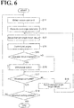
- the normal controller 112 performs the normal control until the time immediately before the start of the correction target section. Specifically, the normal controller 112 controls the multi-articular arm 10 to temporarily stop the movement of the leading end 4.
- FIG. 12A illustrates an example in which the movement of the leading end 4 is temporarily stopping with the tool 5 positioned at the point P9.
- the force guide controller 114 performs the force guide control.
- FIG. 12B illustrates an example in which the leading end 4 has moved from the point P9 to the point P21 in response to a guide manipulation of applying external force TF1 to the robot 2.
- the relative information obtainer 115 obtains the relative command information, and the correction controller 116 performs the correction control.
- the relative information obtainer 115 obtains information concerning a relative command IM1.
- the relative command IM1 is for moving the tool 5 from the point P9 to the point P10 and then from the point P10 to the point P9.
- the relative information obtainer 115 obtains, as the information concerning the relative command IM1, information obtained by subtracting the target position and the target posture at the point P9 from the target position and the target posture specified by the command 011.
- the relative information obtainer 115 obtains the command 011 itself as the information concerning the relative command IM1.
- the recovery controller 117 performs the recovery control. As illustrated in FIG. 12C , the recovery controller 117 controls the multi-articular arm 10 to change the position and the posture at the point P21 respectively to the position and the posture at the point P8.
- step S05 the normal controller 112 checks whether there is an end command for ending the control of the robot 2. Upon determining at step S05 that there is no end command, the controller 100 returns the processing to step S01 to perform the normal control, the force guide control, and the correction control again. Upon determining at step S05 that there is an end command, the controller 100 completes the processing.
- the controller 100 first performs steps S11, S12, and S13.
- the normal controller 112 obtains a motion command from the motion program.
- the normal controller 112 obtains a motion command that is smallest in number among un-executed motion commands in the motion program.
- the normal controller 112 performs an inverse kinematics operation to derive joint angle target values (target values of the motion angles of the joints 41 to 46) for moving the leading end 4 to the target position and the target posture specified by the motion command.
- the normal controller 112 When the time over which the motion command is executed is divided into a plurality of control periods, the normal controller 112 performs, for example, linear interpolation to derive joint angle target values on an individual control period basis. At step S13, the normal controller 112 selects the joint angle target values for the first control period.
- the controller 100 performs steps S14 and S15.
- the normal controller 112 controls the multi-articular arm 10 to cause the actuators 21 to 26 to drive the joints 41 to 46 based on the respective joint angle target values that have been selected.
- the emergency controller 113 checks whether the resistant force has increased.
- step S15 Upon determining at step S15 that the resistant force has increased, the controller 100 performs step S16.
- step S16 the emergency controller 113 performs the withdrawal control. Details of the withdrawal control will be described later.
- step S17 the controller 100 performs step S17.
- the controller 100 Upon determining at step S16 that the resistant force has not increased, the controller 100 performs step S17 without performing step S16.
- step S17 the normal controller 112 checks whether the movement of the leading end 4 based on the motion command is complete. For example, the normal controller 112 checks whether the motion command has been executed in all the control periods.
- step S18 the normal controller 112 selects the joint angle target values for the next control period. Then, the controller 100 returns the processing to step S14 to control again the leading end 4 to move based on the motion command while checking whether the resistant force has increased.
- step S19 the normal controller 112 checks whether the leading end 4 has reached a wait position for the guide manipulation.
- the wait position for the guide manipulation is the target position and the target posture of the leading end 4 specified by the motion command immediately before the start of the correction target section (for example, the target position and the target posture specified by the command 010 in the table of FIG. 3 ).
- the controller 100 Upon determining at step S19 that the leading end 4 has not reached the wait position, the controller 100 returns the processing to step S11 to repeat the normal control until the leading end 4 reaches the wait position. Upon determining at step S19 that the leading end 4 has reached the wait position, the controller 100 completes the normal control. This causes the movement of the leading end 4 to temporarily stop.
- the wait position may not necessarily be the target position and the target posture of the leading end 4 specified by the motion command immediately before the start of the correction target section.
- the wait position may be the target position and the target posture of the leading end 4 specified by a motion command that is two or more levels previous to the correction target section.
- the wait position may be set at a position and a posture that include the target position and the target posture of the leading end 4 at the start point of the correction target section in the movable range of the leading end 4.
- the wait position is the target position and the target posture of the leading end 4 specified by the command 008 (position corresponding to the point P7), which is three levels previous to the correction target section.
- the target position and the target posture of the leading end 4 at the start point of the correction target section (position corresponding to the point P9) is included in the movable range MA1 in relation to the wait position.
- the normal controller 112 may also control the multi-articular arm 10 to temporarily stop the movement of the leading end 4 in response to a stop command signal from the worker.
- the normal controller 112 may obtain the state of the input switch 6 as the stop command signal, and control the multi-articular arm 10 to temporarily stop the movement of the leading end 4 at the time when the input switch 6 is turned on.
- the controller 100 first performs steps S21, S22, and S23.
- the emergency controller 113 derives joint angle target values for alleviating the resistant force.
- the posture of the robot 2 corresponding to the derived joint angle target values will be hereinafter referred to as "withdrawal posture".
- the emergency controller 113 derives joint angle target values of the joints 41 to 46 for alleviating the torques detected by the force sensors 31 to 36.
- the emergency controller 113 performs, for example, linear interpolation to derive joint angle target values on an individual control period basis.
- the emergency controller 113 selects the joint angle target values for the first control period.
- the emergency controller 113 controls the multi-articular arm 10 to cause the actuators 21 to 26 to drive the joints 41 to 46 based on the respective joint angle target values that have been selected.
- step S24 the emergency controller 113 checks whether the posture of the robot 2 is the withdrawal posture. Upon determining at step S24 that the posture of the robot 2 is not the withdrawal posture, the controller 100 performs step S25. At step S25, the normal controller 112 selects the joint angle target values for the next control period. Then, the controller 100 returns the processing to step S23 to repeatedly change the posture of the robot 2 until the posture of the robot 2 becomes the withdrawal posture.
- FIG. 13A illustrates an example in which an arm of the worker contacts the robot 2 during the movement of the tool 5 from the point P7 to the point P8.
- the withdrawal posture of the robot 2 is set at such a posture that is farther away from the arm of the worker (see FIG. 13B ).
- step S26 the emergency controller 113 waits for the resumption command to be input. For example, the emergency controller 113 obtains the state of the input switch 6 as the resumption command signal, and waits for the input switch 6 to be turned on.
- the controller 100 performs steps S31, S32, S33, S34, and S35, as illustrated in FIG. 8 .
- the emergency controller 113 sets a recovery target position.
- the emergency controller 113 sets the recovery target position at the position and the posture of the leading end 4 as of the time immediately before the posture of the robot 2 starts changing to the withdrawal posture.
- the emergency controller 113 performs an inverse kinematics operation to derive joint angle target values (target values of the motion angles of the joints 41 to 46) for moving the leading end 4 to the recovery target position.
- the emergency controller 113 When the time over which the recovery to the recovery target position is performed is divided into a plurality of control periods, the emergency controller 113 performs, for example, linear interpolation to derive joint angle target values on an individual control period basis. At step S33, the emergency controller 113 selects the joint angle target values for the first control period. At step S34, the emergency controller 113 controls the multi-articular arm 10 to cause the actuators 21 to 26 to drive the joints 41 to 46 based on the respective joint angle target values that have been selected. At step S35, the emergency controller 113 checks whether the resistant force has increased.
- step S35 Upon determining at step S35 that the resistant force has increased, the controller 100 returns the processing to step S21. Upon determining at step S35 that the resistant force has not increased, the controller 100 performs step S36. At step S36, the emergency controller 113 checks whether the movement of the leading end 4 to the recovery target position is complete.
- step S37 the emergency controller 113 selects the joint angle target values for the next control period. Then, the controller 100 returns the processing to step S34 to repeatedly move the leading end 4 until the leading end 4 moves to the recovery target position.
- step S36 the controller 100 completes the withdrawal control.
- step S41 the force guide controller 114 waits for the guide-on command to be input.
- the force guide controller 114 obtains the guide-on command signal in the form of the state of the input switch 6 as of the period of time for which the movement of the leading end 4 is temporarily stopping.
- the force guide controller 114 waits for the input switch 6 to be turned on.
- the controller 100 performs steps S42, S43, S44, and S45.
- the force guide controller 114 obtains, as the guide manipulation, information concerning the external force that has been input. For example, the force guide controller 114 obtains a detection result(s) obtained by the force sensors 31 to 36.
- the force guide controller 114 derives the target position and the target posture of the leading end 4 that are based on the external force (this target position and this target posture will be hereinafter referred to as "guide target position"). For example, based on the detection result(s) obtained by the force sensors 31 to 36, the force guide controller 114 derives a force and a moment acting on the leading end 4.
- the force guide controller 114 derives a target position and a target posture of the leading end 4.
- the force guide controller 114 performs an inverse kinematics operation to derive joint angle target values (target values of the motion angles of the joints 41 to 46) for moving the leading end 4 to the guide target position.
- the force guide controller 114 controls the multi-articular arm 10 to cause the actuators 21 to 26 to drive the joints 41 to 46 based on the respective joint angle target values.
- step S46 the correction controller 116 checks whether the resumption command signal has been input. Specifically, the correction controller 116 obtains the resumption command signal in the form of the state of the input switch 6 as of the time after the force guide control, and checks whether the input switch 6 is on. Upon determining at step S46 that the resumption command signal has not been input, the controller 100 returns the processing to step S42 to repeat the force guide control until the resumption command signal is input. Upon determining at step S46 that the resumption command signal has been input, the controller 100 completes the force guide control.
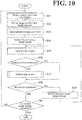
- the controller 100 first performs steps S51 and S52.
- the relative information obtainer 115 obtains the relative command information.
- the relative information obtainer 115 obtains, as the information concerning the relative command IM1, information obtained by subtracting the target position and the target posture at the point P9 from the target position and the target posture specified by the command 011.
- the relative information obtainer 115 obtains the command 011 itself as the information concerning the relative command IM1.
- the correction controller 116 derives, based on the current position and the current posture of the leading end 4, a target position and a target posture that the leading end 4 would take when the relative command information were taken into consideration (this target position and this target posture will be hereinafter referred to as "correction target position").
- this target position and this target posture will be hereinafter referred to as "correction target position"
- the current position and the current posture of the leading end 4 respectively correspond to the position and the posture of the leading end 4 as of the point of time when the movement of the robot 2 under the force guide control ended.
- the controller 100 performs steps S53, S54, and S55.
- the correction controller 116 performs an inverse kinematics operation to derive joint angle target values (target values of the motion angles of the joints 41 to 46) for moving the leading end 4 to the correction target position.
- the correction controller 116 performs, for example, linear interpolation to derive joint angle target values on an individual control period basis.
- the correction controller 116 selects the joint angle target values for the first control period.
- the correction controller 116 controls the multi-articular arm 10 to cause the actuators 21 to 26 to drive the joints 41 to 46 based on the respective joint angle target values that have been selected.
- step S56 the emergency controller 113 checks whether the resistant force has increased. Upon determining that the resistant force has increased, the controller 100 performs step S57. At step S57, the emergency controller 113 performs the withdrawal control, similarly to step S16.
- step S58 the controller 100 performs step S58.
- the controller 100 Upon determining at step S56 that the resistant force has not increased, the controller 100 performs step S58 without performing step S57.
- the correction controller 116 checks whether the movement of the leading end 4 to the correction target position is complete. For example, the correction controller 116 checks whether the motion command has been executed in all the control periods to move the leading end 4 to the correction target position.
- step S59 the correction controller 116 selects the joint angle target values for the next control period. Then, the controller 100 returns the processing to step S55 to repeatedly move the leading end 4 to the correction target position while checking whether the resistant force has increased.
- step S61 the correction controller 116 checks whether the correction control is complete in all the motion commands in the correction target section. Upon determining at step S61 that the correction control is not complete in all the motion commands, the controller 100 returns the processing to step S51 to repeat the correction control until the correction control is complete in all the motion commands in the correction target section. Upon determining at step S61 that the correction control is complete in all the motion commands, the controller 100 completes the correction control. Procedure for Recovery Control
- the controller 100 first performs steps S71, S72, S73, and S74.
- the recovery controller 117 sets a target position and a target posture of the leading end 4 at which to resume the normal control (this target position and this target posture will be hereinafter referred to as "recovery target position").
- the recovery controller 117 sets the recovery target position at the target position and the target posture of the leading end 4 specified by the motion command immediately after the correction target section.
- the recovery controller 117 performs an inverse kinematics operation to derive joint angle target values (target values of the motion angles of the joints 41 to 46) for moving the leading end 4 to the recovery target position.
- the recovery controller 117 performs, for example, linear interpolation to derive joint angle target values on an individual control period basis.
- the recovery controller 117 selects the joint angle target values for the first control period.
- the recovery controller 117 controls the multi-articular arm 10 to cause the actuators 21 to 26 to drive the joints 41 to 46 based on the respective joint angle target values that have been selected.
- step S75 the emergency controller 113 checks whether the resistant force has increased. Upon determining at step S75 that the resistant force has increased, the controller 100 performs step S76. At step S76, the emergency controller 113 performs the withdrawal control, similarly to step S16.
- step S77 the controller 100 performs step S77.
- the controller 100 Upon determining at step S75 that the resistant force has not increased, the controller 100 performs step S77 without performing step S76.
- step S77 the recovery controller 117 checks whether the movement of the leading end 4 to the recovery target position is complete. For example, the recovery controller 117 checks whether the motion command has been executed in all the control periods to move the leading end 4 to the recovery target position.
- step S77 Upon determining at step S77 that the movement of the leading end 4 is not complete, the controller 100 performs step S78.
- step S78 the recovery controller 117 selects the joint angle target values for the next control period. Then, the controller 100 returns the processing to step S74 to repeatedly control the leading end 4 to move to the recovery target position while checking whether the resistant force has increased.
- step S77 the controller 100 completes the recovery control.
- the robot system 1 includes the robot 2, the normal controller 112, the force guide controller 114, the relative information obtainer 115, and the correction controller 116.
- the robot 2 includes the leading end 4, the base 3, and the multi-articular arm 10.
- the multi-articular arm 10 adjusts the position and the posture of the leading end 4 relative to the base 3.
- the normal controller 112 controls the multi-articular arm 10 to move the leading end 4 based on a motion program that specifies a transition over time of a target position and a target posture of the leading end 4 relative to the base 3.
- the force guide controller 114 controls the multi-articular arm 10 to move the leading end 4 in response to a guide manipulation of applying an external force to the robot 2 while the normal controller 112 is controlling the multi-articular arm 10.
- the relative information obtainer 115 obtains relative command information that is based on the target position and the target posture of the leading end 4 at a start point of a correction target section and that specifies the target position and the target posture of the leading end 4 at points of the correction target section including the start point and an end point of the correction target section (the correction target section is a section that is included in the transition and that starts and ends in the transition).
- the correction controller 116 controls the multi-articular arm 10 to, based on the relative command information, move the leading end 4 from the position and the posture of the leading end 4 as of the point of time when movement of the multi-articular arm 10 controlled by the force guide controller 114 ended.
- the robot system 1 includes the force guide controller 114.
- the force guide controller 114 is capable of allowing the worker to perform a guide manipulation of applying an external force to the robot 2 while the robot 2 is working on a workpiece. In this manner, the force guide controller 114 makes the position and the posture of the leading end 4 adapted to the actual environment.
- the robot system 1 includes the correction controller 116.
- the correction controller 116 controls the robot 2 to perform the rest of the work based on the position and the posture of the leading end 4 adapted to the actual environment.
- the robot system 1 is effective for saving labor of human beings in cooperative work of human beings and robots.
- the motion program may include section specifying information that specifies the correction target section.
- the relative information obtainer 115 may obtain the relative command information based on the section specifying information.
- the target section to be controlled by the correction controller is specified in advance in the motion program. This eliminates or minimizes such a situation that relative command information concerning an irrelevant target section is obtained. This, in turn, prevents the robot 2 from performing erroneous work.
- the robot system 1 may further include the recovery controller 117.
- the recovery controller 117 controls the multi-articular arm 10 so that the position and the posture of the leading end 4 as of the point of time when the movement of the multi-articular arm 10 controlled by the correction controller 116 ended change to a position and a posture that are specified in the motion program. This prevents the discrepancy between the motion program and the position and the posture of the leading end 4 from increasing through repeated control of the correction controller 116. This, in turn, eliminates or minimizes degradation of reliability of the work performed by the robot 2.
- the normal controller 112 may control the multi-articular arm 10 to temporarily stop the movement of the leading end 4 while the motion program is being executed. With the movement of the leading end 4 temporarily stopping, the force guide controller 114 may start controlling the multi-articular arm 10 to move the leading end 4 in response to the guide manipulation. Temporarily stopping the motion of the robot 2 facilitates the guide manipulation.
- the motion program may include timing specifying information that specifies a timing to temporarily stop the leading end 4.
- the normal controller 112 may control the multi-articular arm 10 to temporarily stop the movement of the leading end 4 at the timing specified in the timing specifying information.
- a timing at which to temporarily stop the leading end 4 is specified in advance in the motion program. This stabilizes the position to start the guide manipulation. This, in turn, more reliably saves the worker the load associated with the guide manipulation.
- the force guide controller 114 may restrict the movable range of the leading end 4.
- the normal controller 112 may control the multi-articular arm 10 to temporarily stop the leading end 4 with the leading end 4 taking a position and a posture such that the target position and the target posture of the leading end 4 at the start point of the correction target section are included in the movable range.
- the force guide controller 114 may control the multi-articular arm 10 to restrict the movable range of the leading end 4. By restricting the movable range of the leading end 4, an erroneous guide manipulation is eliminated or minimized.
- the force guide controller 114 may control the multi-articular arm 10 to restrict the degree of movement freedom of the leading end 4. By restricting the degree of movement freedom of the leading end 4, an erroneous guide manipulation is eliminated or minimized.
- the correction controller 116 may start controlling the multi-articular arm 10 to move the leading end 4 based on the relative command information. This eliminates or minimizes such a situation that the correction controller 116 controls the multi-articular arm 10 at a timing unexpected for the worker.
- the force guide controller 114 may start controlling the multi-articular arm 10 to move the leading end 4 in response to the guide manipulation. This eliminates or minimizes such a situation that the force guide controller 114 controls the multi-articular arm 10 at a timing unexpected for the worker.
- the normal controller 112 may control the multi-articular arm 10 to temporarily stop the leading end 4 while the motion program is being executed.
- the movement of the leading end 4 can be temporarily stopped at a position desirable for the worker. This provides the worker with improved comfort in performing the guide manipulation.
- the correction controller 116 may start controlling the multi-articular arm 10 to move the leading end 4 based on the relative command information. This ensures that the work performed by the robot 2 is resumed quickly after the guide manipulation made by the worker.
- the robot system 1 may further include the emergency controller 113.
- the emergency controller 113 controls the multi-articular arm 10 to stop the motion, which is against the resistant force.
- the robot 2 may include a plurality of joints 41 to 46. Based on information concerning a torque acting on the plurality of joints 41 to 46, the force guide controller 114 may control the multi-articular arm 10 to move the leading end 4 in response to the guide manipulation. This ensures that the information obtainable at the multi-articular arm 10 can be effectively used in the control performed by the force guide controller 114, resulting in a simplified apparatus configuration.
Landscapes
- Engineering & Computer Science (AREA)
- Robotics (AREA)
- Mechanical Engineering (AREA)
- Physics & Mathematics (AREA)
- General Physics & Mathematics (AREA)
- Automation & Control Theory (AREA)
- Health & Medical Sciences (AREA)
- General Health & Medical Sciences (AREA)
- Orthopedic Medicine & Surgery (AREA)
- Multimedia (AREA)
- Manipulator (AREA)
Abstract
Description
- The present invention relates to a robot system and a method for controlling a robot.
-
JP 2006-82185A - The contents of
JP 2006-82185A - It is an object of the present invention to provide a robot system that is effective for saving labor of a human being in cooperative work performed by the human being and a robot.
- According to one aspect of the present invention, a robot system includes a robot, a normal controller, a force guide controller, a relative information obtainer, and a correction controller. The robot includes a leading end, a base, and a multi-articular arm. The multi-articular arm is configured to adjust a position and a posture of the leading end relative to the base. The normal controller is configured to control the multi-articular arm to move the leading end based on a motion program that specifies a transition over time of a target position and a target posture of the leading end relative to the base. The transition includes a correction target section that starts and ends in the transition. The force guide controller is configured to control the multi-articular arm to move the leading end in response to a guide manipulation of applying an external force to the robot while the normal controller is controlling the multi-articular arm. The relative information obtainer is configured to obtain relative command information that is based on the target position and the target posture of the leading end at a start point of the correction target section and that specifies the target position and the target posture of the leading end at points of the correction target section including the start point and an end point of the correction target section. The correction controller is configured to control the multi-articular arm to, based on the relative command information, move the leading end from the position and the posture of the leading end as of a point of time when movement of the multi-articular arm controlled by the force guide controller ended.
- According to another aspect of the present invention, a method is for controlling a robot. The robot includes a leading end, a base, and a multi-articular arm. The multi-articular arm is configured to adjust a position and a posture of the leading end relative to the base. The method includes performing normal control that includes controlling the multi-articular arm to move the leading end based on a motion program that specifies a transition over time of a target position and a target posture of the leading end relative to the base. The transition includes a correction target section that starts and ends in the transition. Force guide control is performed that includes controlling the multi-articular arm to move the leading end in response to a guide manipulation of applying an external force to the robot during the normal control. Relative command information is obtained that specifies the target position and the target posture of the leading end at a start point through to an end point of the correction target section. Correction control is performed that includes controlling the multi-articular arm to, based on the relative command information, move the leading end from the position and the posture of the leading end as of a point of time when movement of the multi-articular arm controlled by the force guide controller ended.
- The present invention provides a robot system that is effective for saving labor of a human being in cooperative work performed by the human being and a robot.
- A more complete appreciation of the present invention and many of the attendant advantages thereof will be readily obtained as the same becomes better understood by reference to the following detailed description when considered in connection with the accompanying drawings, wherein:
-
FIG. 1 is a schematic illustrating a configuration of a robot system as a whole; -
FIG. 2 is a schematic illustrating a robot's motion that is based on a motion program; -
FIG. 3 is a table illustrating an example motion program; -
FIG. 4 is a block diagram illustrating a hardware configuration of a controller; -
FIG. 5 is a flowchart of an example procedure for controlling the robot; -
FIG. 6 is a flowchart of an example procedure for normal control; -
FIG. 7 is a flowchart of an example procedure for withdrawal control; -
FIG. 8 is a flowchart of an example procedure for the withdrawal control; -
FIG. 9 is a flowchart of an example procedure for force guide control; -
FIG. 10 is a flowchart of an example procedure for correction control; -
FIG. 11 is a flowchart of an example procedure for recovery control; -
FIGs. 12A, 12B, and 12C are schematics illustrating the robot's example motions that are based on the normal control, the force guide control, and the correction control; -
FIGs. 13A and 13B are schematics illustrating the robot's example motions that are based on the withdrawal control; and -
FIG. 14 is a schematic illustrating a relationship between a stopping position and a correction target section. - The embodiments will now be described with reference to the accompanying drawings, wherein like reference numerals designate corresponding or identical elements throughout the various drawings.
- As illustrated in
FIG. 1 , arobot system 1 is a human cooperative system, in which arobot 2 and a worker cooperate with each other. Therobot system 1 includes therobot 2 and acontroller 100. - The
robot 2 is a six-axis vertical multi-articular robot, and includes abase 3, a leadingend 4, amulti-articular arm 10, atool 5, and aninput switch 6. Thebase 3 is disposed on the floor of a workspace of therobot 2. - The
multi-articular arm 10 connects thebase 3 and the leadingend 4 to each other. Themulti-articular arm 10 includes a plurality of joints, and adjusts the position and the posture of the leadingend 4 relative to thebase 3 by changing the angles of the plurality of joints. Themulti-articular arm 10 includes aturnable part 11, alower arm 12, anupper arm 13, a wrist 16,actuators force sensors - The
turnable part 11 is located at an upper part of thebase 3 turnably about vertical axis Ax1. Specifically, themulti-articular arm 10 includes ajoint 41. The joint 41 makes theturnable part 11 turnable about the vertical axis Ax1. - The
lower arm 12 is connected to thelower arm 12 swingably about axis Ax2, which crosses (for example, is orthogonal to) the vertical axis Ax1. Specifically, themulti-articular arm 10 includes a joint 42. The joint 42 makes thelower arm 12 swingable about the axis Ax2. It is to be noted that the terms "cross", "crosses", and "crossing" encompass a skew relationship such as "grade separation". The same applies in the following description. - The
upper arm 13 is connected to an end of thelower arm 12 swingably about axis Ax3, which crosses the vertical axis Ax1. Specifically, themulti-articular arm 10 includes a joint 43. The joint 43 makes theupper arm 13 swingable the axis Ax3. The axis Ax3 may be parallel to the axis Ax2. - The leading end, 15, of the
upper arm 13 is turnable about axis Ax4, which extends along the axial center of theupper arm 13. In other words, the leadingend 15 of theupper arm 13 is turnable relative to the base end, 14, of theupper arm 13. Specifically, themulti-articular arm 10 includes a joint 44. The joint 44 makes theleading end 15 of theupper arm 13 turnable about the axis Ax4. - The wrist 16 is connected to the
leading end 15 of theupper arm 13 swingably about axis Ax5, which crosses (for example, is orthogonal to) the axis Ax4. Specifically, themulti-articular arm 10 includes a joint 45. The joint 45 makes the wrist 16 swingable about the axis Ax5. - The
leading end 4 is connected to the leading end of the wrist 16 turnably about axis Ax6, which extends along the axial center of the wrist 16. Specifically, themulti-articular arm 10 includes a joint 46. The joint 46 makes theleading end 4 turnable about the axis Ax6. - The
actuators multi-articular arm 10. Specifically, theactuator 21 makes theturnable part 11 turn about the vertical axis Ax1; theactuator 22 makes thelower arm 12 swing about the axis Ax2; theactuator 23 makes theupper arm 13 swing about the axis Ax3; theactuator 24 makes theleading end 15 of theupper arm 13 turn about the axis Ax4; theactuator 25 makes the wrist 16 swing about the axis Ax5; and theactuator 26 makes theleading end 4 turn about the axis Ax6. More specifically, theactuators 21 to 26 respectively drive thejoints 41 to 46. Theforce sensors 31 to 36 are strain gauge torque sensors and detect torque acting on therespective joints 41 to 46. - The
tool 5 is mounted on theleading end 4 and used in work performed by therobot 2. Thetool 5 varies in detailed configuration depending on the type of work performed by therobot 2. Examples of thetool 5 include, but are not limited to: a hand to hold workpieces; a driver for screwing purposes; and a welding torch. InFIG. 1 and other drawings, thetool 5 is a hand to hold workpieces. - The
input switch 6 is a switch through which the worker who cooperates with therobot 2 inputs various signals into therobot 2. Examples of the signals that can be input through theinput switch 6 include, but are not limited to: a guide-on signal, described later; a stop command signal, described later; and a resumption command signal, described later. - It is to be noted that the above-described configuration of the
robot 2 is presented for example purposes only, and that therobot 2 may have any other configuration insofar as therobot 2 is capable of adjusting the position and the posture of theleading end 4 relative to thebase 3. For example, therobot 2 may be a seven-axis robot equivalent to the above-described six-axis vertical multi-articular robot plus a redundant axis. For further example, therobot 2 may be a SCARA (Selective Compliance Assembly Robot Arm) robot. - The
controller 100 performs: normal control that includes controlling themulti-articular arm 10 to move theleading end 4 based on a motion program that specifies a transition over time of a target position and a target posture of theleading end 4 relative to thebase 3; force guide control that includes controlling themulti-articular arm 10 to move theleading end 4 in response to a guide manipulation of applying an external force to therobot 2 during the normal control; obtaining relative command information that is based on the target position and the target posture of theleading end 4 at a start point of a correction target section and that specifies the target position and the target posture of theleading end 4 at points of the correction target section including the start point and an end point of the correction target section (the correction target section is a section that is included in the transition and that starts and ends in the transition); performing correction control that includes controlling themulti-articular arm 10 to, based on the relative command information, move theleading end 4 from the position and the posture of theleading end 4 as of the point of time when movement of themulti-articular arm 10 under the force guide control ended. - The
controller 100 includes functional configurations (hereinafter referred to as "functional modules"), namely, amotion program storage 111, anormal controller 112, aforce guide controller 114, arelative information obtainer 115, acorrection controller 116, arecovery controller 117, and anemergency controller 113. - The
motion program storage 111 stores the above-described motion program. The motion program includes a plurality of motion commands aligned in time order. The plurality of motion commands include a motion command for themulti-articular arm 10 and a motion command for thetool 5. The motion command for themulti-articular arm 10 includes a movement command that specifies a target position and a target posture of theleading end 4 relative to thebase 3. It is to be noted that at least some movement commands may be described to specify a relative change of the position and the posture of theleading end 4. When a command is described in this manner, this command will be referred to as "relative command". When, in contrast, a command is described to specify a target position and a target posture of theleading end 4 relative to thebase 3, this command will be referred to as "absolute command". It is difficult or impossible to specify a target position and a target posture of theleading end 4 relative to thebase 3 by relying solely on a relative command. When, however, at least one absolute command is included in the motion program, a target position and a target posture of theleading end 4 relative to thebase 3 can be specified using a relative command based on the target position and the target posture specified by the absolute command. When thetool 5 is a hand, the motion command for thetool 5 includes a workpiece holding command and a workpiece releasing command. The motion program may include section specifying information, which specifies the correction target section. -
FIG. 2 is a schematic illustrating an example motion of therobot 2. As illustrated inFIG. 2 , apart 92 is located in an area WA1, andparts 93 are located in an area WA2. The example motion illustrated inFIG. 2 includes transferring apart 93 from the area WA2 to the area WA1 and inserting the transferredpart 93 into ahole 92a of thepart 92. Point P1 indicates the position of thetool 5 at the time of holding thepart 93. Point P9 indicates the position of thetool 5 at the start of insertion of thepart 93 into thehole 92a. Point P10 indicates the position of thetool 5 at the time of completion of insertion of thepart 93 into thehole 92a. Points P2 to P8 indicate the positions that thetool 5 passes between the points P1 to P9. -
FIG. 3 is a table illustrating an example motion program for causing therobot 2 to make the motion illustrated inFIG. 2 .Command 001 is a command for moving thetool 5 to the point P1. This movement command includes the target position and the target posture of theleading end 4 at the time of positioning thetool 5 at the point P1.Command 002 is a command for causing thetool 5 to hold thepart 93. CommandS003 to 011 are commands for moving thetool 5 respectively to the points P2 to P10. Each of the commandS003 to 011 includes the target position and the target posture of theleading end 4 at the time of positioning thetool 5 at the corresponding destination point.Command 012 is a command for causing thetool 5 to release thepart 93.Command 013 is a command for moving thetool 5 to the point P9 after thetool 5 has released thepart 93. Thecommand 013 includes the target position and the target posture of theleading end 4 at the time of positioning thetool 5 at the point P9.Command 014 and the commands that follow thecommand 14 are commands for returning thetool 5 to the area WA2. "Correction target flag" in the table ofFIG. 3 corresponds to the above-described section specifying information. The correction target flag is set on an individual command basis, and indicates whether the movement section of the corresponding command is a correction target section. Specifically, "0" indicates that the movement section is not a correction target section, and "1" indicates that the movement section is a correction target section. Specific examples of the above description will be provided below by referring toFIGs. 2 and3 as necessary. - The
normal controller 112 controls themulti-articular arm 10 to move theleading end 4 based on a motion program that specifies a transition over time of the target position and the target posture of theleading end 4 relative to thebase 3. This control will be hereinafter referred to as "normal control". For example, in order to move the position and the posture of theleading end 4 relative to thebase 3 to a target position and a target posture specified in the motion program, thenormal controller 112 derives target motion angles of thejoints 41 to 46, and controls themulti-articular arm 10 to follow the motion angles of thejoints 41 to 46. Thenormal controller 112 may control themulti-articular arm 10 to temporarily stop the movement of theleading end 4 while the motion program is being executed. - Timing specifying information specifies a timing at which to temporarily stop the movement of the
leading end 4. When the motion program includes the timing specifying information, thenormal controller 112 may control themulti-articular arm 10 to temporarily stop the movement of theleading end 4 at the timing specified in the timing specifying information. For example, thenormal controller 112 obtains the above-described section specifying information as the timing specifying information, and controls themulti-articular arm 10 to temporarily stop the movement of theleading end 4 immediately before the start of the correction target section. More specifically, thenormal controller 112 controls themulti-articular arm 10 to temporarily stop the movement of theleading end 4 immediately before the correction target flag in the table ofFIG. 3 changes from 0 to 1 (between thecommands 010 and 011). - The
force guide controller 114 controls themulti-articular arm 10 to move theleading end 4 in response to a guide manipulation of applying an external force to therobot 2 while thenormal controller 112 is controlling themulti-articular arm 10. This control will be hereinafter referred to as "force guide control". In the human-cooperative robot system 1, an external force of guide manipulation is applied to therobot 2 by the worker contacting therobot 2. As used herein, the term "external force" encompasses force and moment, and the terms "move", "movement", and "moving" refer to a change of at least one of position and posture. - For example, in order to move the
leading end 4 in the direction in which the external force is being applied, theforce guide controller 114 derives a target position and a target posture of theleading end 4; derives target motion angles of thejoints 41 to 46 to move theleading end 4 to the target position and target posture that have been derived; and controls themulti-articular arm 10 to follow the motion angles of thejoints 41 to 46. - The
force guide controller 114 may start the force guide control with the movement of theleading end 4 temporarily stopping while the motion program is being executed, and prohibit the force guide control until the movement of theleading end 4 comes to a temporary stop. In the force guide control, theforce guide controller 114 may control themulti-articular arm 10 to restrict the movable range of theleading end 4. For example, theforce guide controller 114 may restrict the movable range of the position and/or the posture of theleading end 4, or may restrict the movable ranges of thejoints 41 to 46. Also, theforce guide controller 114 may restrict the time for which to move theleading end 4 in response to the guide manipulation, thereby restricting the movable range of the position and/or the posture of theleading end 4. - In the force guide control, the
force guide controller 114 may control themulti-articular arm 10 to restrict the degree of movement freedom of theleading end 4. Examples of how to restrict the degree of movement freedom of theleading end 4 include, but are not limited to: to prevent the posture of theleading end 4 from changing about a predetermined axis; to prevent theleading end 4 from moving along a predetermined axis; and to prevent the posture of theleading end 4 from changing while permitting the position of theleading end 4 to change. - The
force guide controller 114 may start the force guide control in response to a guide-on command signal from the worker, and prohibit the force guide control until the guide-on command signal is input. For example, theforce guide controller 114 may obtain the guide-on command signal in the form of the state of theinput switch 6 as of the period of time for which the movement of theleading end 4 is temporarily stopping. Then, theforce guide controller 114 may start the force guide control at the time when theinput switch 6 is turned on. It is to be noted that the guide-on command signal will not be limited to the state of theinput switch 6. For example, based on a detection result(s) obtained by theforce sensors 31 to 36, theforce guide controller 114 may detect the worker's manipulation of applying a predetermined external force to the robot 2 (for example, tapping on the robot 2). Upon detection of the manipulation, theforce guide controller 114 may start the force guide control. - The
force guide controller 114 may perform the force guide control based on information concerning a torque(s) acting on the plurality ofjoints 41 to 46. Specifically, theforce guide controller 114 may derive the above-described external force based on the torque(s) acting on thejoints 41 to 46. Then, based on the external force, theforce guide controller 114 may control themulti-articular arm 10 to move theleading end 4. Theforce guide controller 114 may check a detection result(s) obtained by theforce sensors 31 to 36 as the information concerning the torque(s) acting on thejoints 41 to 46. In another possible embodiment, theforce guide controller 114 may check a detection result(s) of deflection angles of the axes of thejoints 41 to 46 as the information concerning the torque(s) acting on thejoints 41 to 46. The deflection angles are torsion angles calculated based on the rotational angles of theactuators 21 to 26, the reduction ratio of the axis of each joint, and/or the rotational angles of thejoints 41 to 46. Although this necessitates two angle sensors per joint axis, it is not necessary to provide theforce sensors 31 to 36. In another possible embodiment, theforce guide controller 114 may check a torque(s) output from theactuators 21 to 26 as the information concerning the torque(s) acting on thejoints 41 to 46. The torque output from theactuators 21 to 26 can be derived based on a current(s) supplied to theactuators 21 to 26. - The
relative information obtainer 115 obtains relative command information from the motion program. The relative command information specifies the target position and the target posture of theleading end 4 at the start point through to the end point of the correction target section. For example, therelative information obtainer 115 obtains the relative command information based on the section specifying information included in the motion program. Specifically, therelative information obtainer 115 obtains the relative command information such that the target position and the target posture at the start point correspond to the target position and the target posture as of the time immediately before the correction target flag changes from 0 to 1 (for example, the target position and the target posture corresponding to thecommand 010 in the table ofFIG. 3 ). - When a motion command in a correction target section is an "absolute command", the
relative information obtainer 115 obtains, as the relative command information, information obtained by subtracting the target position and the target posture at the start point from the target position and the target posture specified by the motion command. When a motion command in a correction target section is a "relative command", therelative information obtainer 115 obtains the motion command itself as the relative command information. - Based on the relative command information obtained by the
relative information obtainer 115, thecorrection controller 116 controls themulti-articular arm 10 to move theleading end 4 from the position and the posture of theleading end 4 as of the point of time when the movement of themulti-articular arm 10 under the force guide control ended (this position and this posture may occasionally be referred to as "the position and the posture after the force guide control"). This control will be hereinafter referred to as "correction control". - The
correction controller 116 may start the correction control in response to a resumption command signal from the worker. In this case, the resumption command signal may be input from the worker by contacting therobot 2, so that thecorrection controller 116 may start the correction control in response to the resumption command signal. Specifically, thecorrection controller 116 may obtain the resumption command signal in the form of the state of theinput switch 6 as of the time after the force guide control, and may start the correction control at the time when theinput switch 6 is turned on. It is to be noted that the resumption command signal will not be limited to the state of theinput switch 6. For example, based on a detection result(s) obtained by theforce sensors 31 to 36, thecorrection controller 116 may detect the worker's manipulation of applying a predetermined external force to the robot 2 (for example, tapping on the robot 2). Upon detection of the manipulation, thecorrection controller 116 may start the correction control. - the
recovery controller 117 controls themulti-articular arm 10 so that the position and the posture of theleading end 4 as of the point of time when the movement of themulti-articular arm 10 controlled by thecorrection controller 116 ended change to a position and a posture that are specified in the motion program. This control will be hereinafter referred to as "recovery control". - A resistant force may occur against the motions that the
robot 2 makes under the control of thenormal controller 112, thecorrection controller 116, and therecovery controller 117. In response to an increase of the resistant force, theemergency controller 113 controls themulti-articular arm 10 to stop a motion against the resistant force. For example, the resistant force can increase when the worker contacts therobot 2. For further example, the resistant force can increase when an arm or another part of the body of the worker has become caught between the components of the robot 2 (for example, between thelower arm 12 and the upper arm 13). An increase of the resistant force is detectable based on a detection result(s) obtained by theforce sensors 31 to 36. As used herein, the phrase "stop a motion against the resistant force" not only refers to stopping a motion of therobot 2 but also encompasses moving therobot 2 in the direction in which the resistant force is acting (direction in which the resistant force is alleviated). The motion to "stop a motion against the resistant force" will be hereinafter referred to as "withdrawal motion". -
FIG. 4 is a block diagram illustrating a hardware configuration of thecontroller 100. As illustrated inFIG. 4 , thecontroller 100 includes acircuit 120. Thecircuit 120 includes at least oneprocessor 121, amemory 122, astorage 123, adriver 124, and an input/output port 125. Thestorage 123 is a computer-readable non-volatile storage medium (for example, a hard disc or a flash memory). Thestorage 123 includes a storage area in which programs for implementing the functional modules of thecontroller 100 are stored; and a storage area assigned to themotion program storage 111. Thememory 122 is a temporary storage for programs loaded from thestorage 123 and for results of operations performed by theprocessor 121. Theprocessor 121 cooperates with thememory 122 to execute the programs, thereby implementing the functional modules of thecontroller 100. Thedriver 124, at a command from theprocessor 121, outputs drive power to the motors of theactuators 21 to 26. The input/output port 125, at a command from theprocessor 121, inputs and outputs electric signals from and to theforce sensors 31 to 36. - It is to be noted that the
circuit 120 may not necessarily implement the functions using programs. For example, thecircuit 120 may implement at least some of the functions using dedicated logic circuits or an application specific integrated circuit (ASIC) in which the dedicated logic circuits are integrated. - An example method for controlling the
robot 2 will be described. The example method is performed by thecontroller 100, and a procedure for control performed by thecontroller 100 will be described below. This procedure includes performing: normal control that includes controlling themulti-articular arm 10 to move theleading end 4 based on a motion program that specifies a transition over time of a target position and a target posture of theleading end 4 relative to thebase 3; force guide control that includes controlling themulti-articular arm 10 to move theleading end 4 in response to a guide manipulation of applying an external force to therobot 2 during the normal control; obtaining relative command information that is based on the target position and the target posture of theleading end 4 at a start point of a correction target section and that specifies the target position and the target posture of theleading end 4 at points of the correction target section including the start point and an end point of the correction target section (the correction target section is a section that is included in the transition and that starts and ends in the transition); performing correction control that includes controlling themulti-articular arm 10 to, based on the relative command information, move theleading end 4 from the position and the posture of theleading end 4 as of the point of time when movement of themulti-articular arm 10 under the force guide control ended. - As illustrated in
FIG. 5 , thecontroller 100 performs steps S01, S02, S03, and S04. At step S01, thenormal controller 112 performs the normal control until the time immediately before the start of the correction target section. Specifically, thenormal controller 112 controls themulti-articular arm 10 to temporarily stop the movement of theleading end 4.FIG. 12A illustrates an example in which the movement of theleading end 4 is temporarily stopping with thetool 5 positioned at the point P9. At step S02, theforce guide controller 114 performs the force guide control.FIG. 12B illustrates an example in which theleading end 4 has moved from the point P9 to the point P21 in response to a guide manipulation of applying external force TF1 to therobot 2. At step S03, therelative information obtainer 115 obtains the relative command information, and thecorrection controller 116 performs the correction control. - As illustrated in
FIG. 12C , therelative information obtainer 115 obtains information concerning a relative command IM1. The relative command IM1 is for moving thetool 5 from the point P9 to the point P10 and then from the point P10 to the point P9. When thecommand 011 is described in the absolute command form, therelative information obtainer 115 obtains, as the information concerning the relative command IM1, information obtained by subtracting the target position and the target posture at the point P9 from the target position and the target posture specified by thecommand 011. When thecommand 011 is described in the relative command form, therelative information obtainer 115 obtains thecommand 011 itself as the information concerning the relative command IM1. - At step S04, the
recovery controller 117 performs the recovery control. As illustrated inFIG. 12C , therecovery controller 117 controls themulti-articular arm 10 to change the position and the posture at the point P21 respectively to the position and the posture at the point P8. - Next, the
controller 100 performs step S05. At step S05, thenormal controller 112 checks whether there is an end command for ending the control of therobot 2. Upon determining at step S05 that there is no end command, thecontroller 100 returns the processing to step S01 to perform the normal control, the force guide control, and the correction control again. Upon determining at step S05 that there is an end command, thecontroller 100 completes the processing. - An example procedure for the normal control performed at step S01 will be described. As illustrated in
FIG. 6 , thecontroller 100 first performs steps S11, S12, and S13. At step S11, thenormal controller 112 obtains a motion command from the motion program. For example, thenormal controller 112 obtains a motion command that is smallest in number among un-executed motion commands in the motion program. At step S12, thenormal controller 112 performs an inverse kinematics operation to derive joint angle target values (target values of the motion angles of thejoints 41 to 46) for moving theleading end 4 to the target position and the target posture specified by the motion command. When the time over which the motion command is executed is divided into a plurality of control periods, thenormal controller 112 performs, for example, linear interpolation to derive joint angle target values on an individual control period basis. At step S13, thenormal controller 112 selects the joint angle target values for the first control period. - Next, the
controller 100 performs steps S14 and S15. At step S14, thenormal controller 112 controls themulti-articular arm 10 to cause theactuators 21 to 26 to drive thejoints 41 to 46 based on the respective joint angle target values that have been selected. At step S15, theemergency controller 113 checks whether the resistant force has increased. - Upon determining at step S15 that the resistant force has increased, the
controller 100 performs step S16. At step S16, theemergency controller 113 performs the withdrawal control. Details of the withdrawal control will be described later. - Next, the
controller 100 performs step S17. Upon determining at step S16 that the resistant force has not increased, thecontroller 100 performs step S17 without performing step S16. At step S17, thenormal controller 112 checks whether the movement of theleading end 4 based on the motion command is complete. For example, thenormal controller 112 checks whether the motion command has been executed in all the control periods. - Upon determining at step S17 that the motion command has not been executed in all the control periods, the
controller 100 performs step S18. At step S18, thenormal controller 112 selects the joint angle target values for the next control period. Then, thecontroller 100 returns the processing to step S14 to control again theleading end 4 to move based on the motion command while checking whether the resistant force has increased. - Upon determining at step S17 that the motion command has been executed in all the control periods, the
controller 100 performs step S19. At step S19, thenormal controller 112 checks whether theleading end 4 has reached a wait position for the guide manipulation. The wait position for the guide manipulation is the target position and the target posture of theleading end 4 specified by the motion command immediately before the start of the correction target section (for example, the target position and the target posture specified by thecommand 010 in the table ofFIG. 3 ). - Upon determining at step S19 that the
leading end 4 has not reached the wait position, thecontroller 100 returns the processing to step S11 to repeat the normal control until theleading end 4 reaches the wait position. Upon determining at step S19 that theleading end 4 has reached the wait position, thecontroller 100 completes the normal control. This causes the movement of theleading end 4 to temporarily stop. It is to be noted that the wait position may not necessarily be the target position and the target posture of theleading end 4 specified by the motion command immediately before the start of the correction target section. For example, the wait position may be the target position and the target posture of theleading end 4 specified by a motion command that is two or more levels previous to the correction target section. In this case, the wait position may be set at a position and a posture that include the target position and the target posture of theleading end 4 at the start point of the correction target section in the movable range of theleading end 4. In the example illustrated inFIG. 14 , the wait position is the target position and the target posture of theleading end 4 specified by the command 008 (position corresponding to the point P7), which is three levels previous to the correction target section. In this case, the target position and the target posture of theleading end 4 at the start point of the correction target section (position corresponding to the point P9) is included in the movable range MA1 in relation to the wait position. - The
normal controller 112 may also control themulti-articular arm 10 to temporarily stop the movement of theleading end 4 in response to a stop command signal from the worker. In this case, thenormal controller 112 may obtain the state of theinput switch 6 as the stop command signal, and control themulti-articular arm 10 to temporarily stop the movement of theleading end 4 at the time when theinput switch 6 is turned on. - An example procedure for the withdrawal control performed at step S16 will be described. As illustrated in
FIG. 7 , thecontroller 100 first performs steps S21, S22, and S23. At step S21, theemergency controller 113 derives joint angle target values for alleviating the resistant force. The posture of therobot 2 corresponding to the derived joint angle target values will be hereinafter referred to as "withdrawal posture". For example, theemergency controller 113 derives joint angle target values of thejoints 41 to 46 for alleviating the torques detected by theforce sensors 31 to 36. When the time over which the withdrawal control is performed is divided into a plurality of control periods, theemergency controller 113 performs, for example, linear interpolation to derive joint angle target values on an individual control period basis. At step S22, theemergency controller 113 selects the joint angle target values for the first control period. At step S23, theemergency controller 113 controls themulti-articular arm 10 to cause theactuators 21 to 26 to drive thejoints 41 to 46 based on the respective joint angle target values that have been selected. - Next, the
controller 100 performs step S24. At step S24, theemergency controller 113 checks whether the posture of therobot 2 is the withdrawal posture. Upon determining at step S24 that the posture of therobot 2 is not the withdrawal posture, thecontroller 100 performs step S25. At step S25, thenormal controller 112 selects the joint angle target values for the next control period. Then, thecontroller 100 returns the processing to step S23 to repeatedly change the posture of therobot 2 until the posture of therobot 2 becomes the withdrawal posture. -
FIG. 13A illustrates an example in which an arm of the worker contacts therobot 2 during the movement of thetool 5 from the point P7 to the point P8. In this case, by changing the joint angle target values of thejoints 41 to 46 in a manner that alleviates the torques detected by theforce sensors 31 to 36, the withdrawal posture of therobot 2 is set at such a posture that is farther away from the arm of the worker (seeFIG. 13B ). - Upon determining at step S24 that the posture of the
robot 2 is the withdrawal posture, thecontroller 100 performs step S26. At step S26, theemergency controller 113 waits for the resumption command to be input. For example, theemergency controller 113 obtains the state of theinput switch 6 as the resumption command signal, and waits for theinput switch 6 to be turned on. - Next, the
controller 100 performs steps S31, S32, S33, S34, and S35, as illustrated inFIG. 8 . At step S31, theemergency controller 113 sets a recovery target position. For example, theemergency controller 113 sets the recovery target position at the position and the posture of theleading end 4 as of the time immediately before the posture of therobot 2 starts changing to the withdrawal posture. At step S32, theemergency controller 113 performs an inverse kinematics operation to derive joint angle target values (target values of the motion angles of thejoints 41 to 46) for moving theleading end 4 to the recovery target position. When the time over which the recovery to the recovery target position is performed is divided into a plurality of control periods, theemergency controller 113 performs, for example, linear interpolation to derive joint angle target values on an individual control period basis. At step S33, theemergency controller 113 selects the joint angle target values for the first control period. At step S34, theemergency controller 113 controls themulti-articular arm 10 to cause theactuators 21 to 26 to drive thejoints 41 to 46 based on the respective joint angle target values that have been selected. At step S35, theemergency controller 113 checks whether the resistant force has increased. - Upon determining at step S35 that the resistant force has increased, the
controller 100 returns the processing to step S21. Upon determining at step S35 that the resistant force has not increased, thecontroller 100 performs step S36. At step S36, theemergency controller 113 checks whether the movement of theleading end 4 to the recovery target position is complete. - Upon determining at step S36 that the movement of the
leading end 4 is not complete, thecontroller 100 performs step S37. At step S37, theemergency controller 113 selects the joint angle target values for the next control period. Then, thecontroller 100 returns the processing to step S34 to repeatedly move theleading end 4 until theleading end 4 moves to the recovery target position. Upon determining at step S36 that the movement of theleading end 4 is complete, thecontroller 100 completes the withdrawal control. Procedure for Force Guide Control - An example procedure for the force guide control performed at step S02 will be described. As illustrated in
FIG. 9 , thecontroller 100 first performs step S41. At step S41, theforce guide controller 114 waits for the guide-on command to be input. For example, theforce guide controller 114 obtains the guide-on command signal in the form of the state of theinput switch 6 as of the period of time for which the movement of theleading end 4 is temporarily stopping. Theforce guide controller 114 waits for theinput switch 6 to be turned on. - Next, the
controller 100 performs steps S42, S43, S44, and S45. At step S42, theforce guide controller 114 obtains, as the guide manipulation, information concerning the external force that has been input. For example, theforce guide controller 114 obtains a detection result(s) obtained by theforce sensors 31 to 36. At step S43, theforce guide controller 114 derives the target position and the target posture of theleading end 4 that are based on the external force (this target position and this target posture will be hereinafter referred to as "guide target position"). For example, based on the detection result(s) obtained by theforce sensors 31 to 36, theforce guide controller 114 derives a force and a moment acting on theleading end 4. Then, based on the force and the moment, theforce guide controller 114 derives a target position and a target posture of theleading end 4. At step S44, theforce guide controller 114 performs an inverse kinematics operation to derive joint angle target values (target values of the motion angles of thejoints 41 to 46) for moving theleading end 4 to the guide target position. At step S45, theforce guide controller 114 controls themulti-articular arm 10 to cause theactuators 21 to 26 to drive thejoints 41 to 46 based on the respective joint angle target values. - Next, the
controller 100 performs step S46. At step S46, thecorrection controller 116 checks whether the resumption command signal has been input. Specifically, thecorrection controller 116 obtains the resumption command signal in the form of the state of theinput switch 6 as of the time after the force guide control, and checks whether theinput switch 6 is on. Upon determining at step S46 that the resumption command signal has not been input, thecontroller 100 returns the processing to step S42 to repeat the force guide control until the resumption command signal is input. Upon determining at step S46 that the resumption command signal has been input, thecontroller 100 completes the force guide control. - An example procedure for the correction control performed at step S03 will be described. As illustrated in
FIG. 10 , thecontroller 100 first performs steps S51 and S52. At step S51, therelative information obtainer 115 obtains the relative command information. When thecommand 011 is described in the absolute command form, therelative information obtainer 115 obtains, as the information concerning the relative command IM1, information obtained by subtracting the target position and the target posture at the point P9 from the target position and the target posture specified by thecommand 011. When thecommand 011 is described in the relative command form, therelative information obtainer 115 obtains thecommand 011 itself as the information concerning the relative command IM1. At step S52, thecorrection controller 116 derives, based on the current position and the current posture of theleading end 4, a target position and a target posture that theleading end 4 would take when the relative command information were taken into consideration (this target position and this target posture will be hereinafter referred to as "correction target position"). When a motion command corresponding to the relative command information is the first motion command in the correction target section, the current position and the current posture of theleading end 4 respectively correspond to the position and the posture of theleading end 4 as of the point of time when the movement of therobot 2 under the force guide control ended. - Next, the
controller 100 performs steps S53, S54, and S55. At step S53, thecorrection controller 116 performs an inverse kinematics operation to derive joint angle target values (target values of the motion angles of thejoints 41 to 46) for moving theleading end 4 to the correction target position. When the time over which theleading end 4 is moved to the correction target position is divided into a plurality of control periods, thecorrection controller 116 performs, for example, linear interpolation to derive joint angle target values on an individual control period basis. At step S54, thecorrection controller 116 selects the joint angle target values for the first control period. At step S55, thecorrection controller 116 controls themulti-articular arm 10 to cause theactuators 21 to 26 to drive thejoints 41 to 46 based on the respective joint angle target values that have been selected. - Next, the
controller 100 performs step S56. At step S56, theemergency controller 113 checks whether the resistant force has increased. Upon determining that the resistant force has increased, thecontroller 100 performs step S57. At step S57, theemergency controller 113 performs the withdrawal control, similarly to step S16. - Next, the
controller 100 performs step S58. Upon determining at step S56 that the resistant force has not increased, thecontroller 100 performs step S58 without performing step S57. At step S58, thecorrection controller 116 checks whether the movement of theleading end 4 to the correction target position is complete. For example, thecorrection controller 116 checks whether the motion command has been executed in all the control periods to move theleading end 4 to the correction target position. - Upon determining at step S58 that the motion command has not been executed in all the control periods, the
controller 100 performs step S59. At step S59, thecorrection controller 116 selects the joint angle target values for the next control period. Then, thecontroller 100 returns the processing to step S55 to repeatedly move theleading end 4 to the correction target position while checking whether the resistant force has increased. - Upon determining at step S58 that the movement of the
leading end 4 is complete, thecontroller 100 performs step S61. At step S61, thecorrection controller 116 checks whether the correction control is complete in all the motion commands in the correction target section. Upon determining at step S61 that the correction control is not complete in all the motion commands, thecontroller 100 returns the processing to step S51 to repeat the correction control until the correction control is complete in all the motion commands in the correction target section. Upon determining at step S61 that the correction control is complete in all the motion commands, thecontroller 100 completes the correction control. Procedure for Recovery Control - An example procedure for the recovery control performed at step S04 will be described. As illustrated in
FIG. 11 , thecontroller 100 first performs steps S71, S72, S73, and S74. At step S71, therecovery controller 117 sets a target position and a target posture of theleading end 4 at which to resume the normal control (this target position and this target posture will be hereinafter referred to as "recovery target position"). For example, therecovery controller 117 sets the recovery target position at the target position and the target posture of theleading end 4 specified by the motion command immediately after the correction target section. At step S72, therecovery controller 117 performs an inverse kinematics operation to derive joint angle target values (target values of the motion angles of thejoints 41 to 46) for moving theleading end 4 to the recovery target position. When the time over which theleading end 4 is moved to the recovery target position is divided into a plurality of control periods, therecovery controller 117 performs, for example, linear interpolation to derive joint angle target values on an individual control period basis. At step S73, therecovery controller 117 selects the joint angle target values for the first control period. At step S74, therecovery controller 117 controls themulti-articular arm 10 to cause theactuators 21 to 26 to drive thejoints 41 to 46 based on the respective joint angle target values that have been selected. - Next, the
controller 100 performs step S75. At step S75, theemergency controller 113 checks whether the resistant force has increased. Upon determining at step S75 that the resistant force has increased, thecontroller 100 performs step S76. At step S76, theemergency controller 113 performs the withdrawal control, similarly to step S16. - Next, the
controller 100 performs step S77. Upon determining at step S75 that the resistant force has not increased, thecontroller 100 performs step S77 without performing step S76. At step S77, therecovery controller 117 checks whether the movement of theleading end 4 to the recovery target position is complete. For example, therecovery controller 117 checks whether the motion command has been executed in all the control periods to move theleading end 4 to the recovery target position. - Upon determining at step S77 that the movement of the
leading end 4 is not complete, thecontroller 100 performs step S78. At step S78, therecovery controller 117 selects the joint angle target values for the next control period. Then, thecontroller 100 returns the processing to step S74 to repeatedly control theleading end 4 to move to the recovery target position while checking whether the resistant force has increased. Upon determining at step S77 that the movement of theleading end 4 is complete, thecontroller 100 completes the recovery control. - As has been described hereinbefore, the
robot system 1 includes therobot 2, thenormal controller 112, theforce guide controller 114, therelative information obtainer 115, and thecorrection controller 116. Therobot 2 includes theleading end 4, thebase 3, and themulti-articular arm 10. Themulti-articular arm 10 adjusts the position and the posture of theleading end 4 relative to thebase 3. Thenormal controller 112 controls themulti-articular arm 10 to move theleading end 4 based on a motion program that specifies a transition over time of a target position and a target posture of theleading end 4 relative to thebase 3. Theforce guide controller 114 controls themulti-articular arm 10 to move theleading end 4 in response to a guide manipulation of applying an external force to therobot 2 while thenormal controller 112 is controlling themulti-articular arm 10. Therelative information obtainer 115 obtains relative command information that is based on the target position and the target posture of theleading end 4 at a start point of a correction target section and that specifies the target position and the target posture of theleading end 4 at points of the correction target section including the start point and an end point of the correction target section (the correction target section is a section that is included in the transition and that starts and ends in the transition). Thecorrection controller 116 controls themulti-articular arm 10 to, based on the relative command information, move theleading end 4 from the position and the posture of theleading end 4 as of the point of time when movement of themulti-articular arm 10 controlled by theforce guide controller 114 ended. - For robots to repeat highly accurate work based on motion programs, it is necessary for robots to work in unchanging work environments. In actual situations, however, robots may occasionally work in varied work environments (hereinafter referred to as "actual environment"). For example, workpieces may be arranged at varied positions and/or postures. In light of the circumstances, the
robot system 1 according to this embodiment includes theforce guide controller 114. Theforce guide controller 114 is capable of allowing the worker to perform a guide manipulation of applying an external force to therobot 2 while therobot 2 is working on a workpiece. In this manner, theforce guide controller 114 makes the position and the posture of theleading end 4 adapted to the actual environment. Further, therobot system 1 includes thecorrection controller 116. Thecorrection controller 116 controls therobot 2 to perform the rest of the work based on the position and the posture of theleading end 4 adapted to the actual environment. Thus, therobot system 1 is effective for saving labor of human beings in cooperative work of human beings and robots. - The motion program may include section specifying information that specifies the correction target section. The
relative information obtainer 115 may obtain the relative command information based on the section specifying information. Thus, the target section to be controlled by the correction controller is specified in advance in the motion program. This eliminates or minimizes such a situation that relative command information concerning an irrelevant target section is obtained. This, in turn, prevents therobot 2 from performing erroneous work. - The
robot system 1 may further include therecovery controller 117. Therecovery controller 117 controls themulti-articular arm 10 so that the position and the posture of theleading end 4 as of the point of time when the movement of themulti-articular arm 10 controlled by thecorrection controller 116 ended change to a position and a posture that are specified in the motion program. This prevents the discrepancy between the motion program and the position and the posture of theleading end 4 from increasing through repeated control of thecorrection controller 116. This, in turn, eliminates or minimizes degradation of reliability of the work performed by therobot 2. - The
normal controller 112 may control themulti-articular arm 10 to temporarily stop the movement of theleading end 4 while the motion program is being executed. With the movement of theleading end 4 temporarily stopping, theforce guide controller 114 may start controlling themulti-articular arm 10 to move theleading end 4 in response to the guide manipulation. Temporarily stopping the motion of therobot 2 facilitates the guide manipulation. - The motion program may include timing specifying information that specifies a timing to temporarily stop the
leading end 4. Thenormal controller 112 may control themulti-articular arm 10 to temporarily stop the movement of theleading end 4 at the timing specified in the timing specifying information. Thus, a timing at which to temporarily stop theleading end 4 is specified in advance in the motion program. This stabilizes the position to start the guide manipulation. This, in turn, more reliably saves the worker the load associated with the guide manipulation. - When the
force guide controller 114 controls themulti-articular arm 10 to move theleading end 4 in response to the guide manipulation, theforce guide controller 114 may restrict the movable range of theleading end 4. Thenormal controller 112 may control themulti-articular arm 10 to temporarily stop theleading end 4 with theleading end 4 taking a position and a posture such that the target position and the target posture of theleading end 4 at the start point of the correction target section are included in the movable range. By restricting the movable range of theleading end 4, an erroneous guide manipulation is eliminated or minimized. Also, restricting the movable range of theleading end 4 prevents the movable range from becoming excessively small in correcting the position and the posture on which the relative command information is based. - When the
force guide controller 114 controls themulti-articular arm 10 to move theleading end 4 in response to the guide manipulation, theforce guide controller 114 may control themulti-articular arm 10 to restrict the movable range of theleading end 4. By restricting the movable range of theleading end 4, an erroneous guide manipulation is eliminated or minimized. - When the
force guide controller 114 controls themulti-articular arm 10 to move theleading end 4 in response to the guide manipulation, theforce guide controller 114 may control themulti-articular arm 10 to restrict the degree of movement freedom of theleading end 4. By restricting the degree of movement freedom of theleading end 4, an erroneous guide manipulation is eliminated or minimized. - In response to a resumption command signal from the worker, the
correction controller 116 may start controlling themulti-articular arm 10 to move theleading end 4 based on the relative command information. This eliminates or minimizes such a situation that thecorrection controller 116 controls themulti-articular arm 10 at a timing unexpected for the worker. - In response to a guide-on command signal from the worker, the
force guide controller 114 may start controlling themulti-articular arm 10 to move theleading end 4 in response to the guide manipulation. This eliminates or minimizes such a situation that theforce guide controller 114 controls themulti-articular arm 10 at a timing unexpected for the worker. - In response to a stop command signal from the worker, the
normal controller 112 may control themulti-articular arm 10 to temporarily stop theleading end 4 while the motion program is being executed. Thus, the movement of theleading end 4 can be temporarily stopped at a position desirable for the worker. This provides the worker with improved comfort in performing the guide manipulation. - In response to a resumption command signal from the worker by contacting the robot (2), the
correction controller 116 may start controlling themulti-articular arm 10 to move theleading end 4 based on the relative command information. This ensures that the work performed by therobot 2 is resumed quickly after the guide manipulation made by the worker. - The
robot system 1 may further include theemergency controller 113. in response to an increase of a resistant force against a motion of therobot 2 controlled by thenormal controller 112, theemergency controller 113 controls themulti-articular arm 10 to stop the motion, which is against the resistant force. - The
robot 2 may include a plurality ofjoints 41 to 46. Based on information concerning a torque acting on the plurality ofjoints 41 to 46, theforce guide controller 114 may control themulti-articular arm 10 to move theleading end 4 in response to the guide manipulation. This ensures that the information obtainable at themulti-articular arm 10 can be effectively used in the control performed by theforce guide controller 114, resulting in a simplified apparatus configuration. - Obviously, numerous modifications and variations of the present invention are possible in light of the above teachings. It is therefore to be understood that within the scope of the appended claims, the present invention may be practiced otherwise than as specifically described herein.
- 1 ... Robot system, 2 ... Robot, 3 ... Base, 4 ... Leading end, 10 ... Multi-articular arm, 41 to 46 ... Joint, 112 ... Normal controller, 113 ... Emergency controller, 114 ... Force guide controller, 115 ... Relative information obtainer, 116 ... Correction controller, 117 ... Recovery controller
Claims (15)
- A robot system (1), characterized by:a robot (2) comprising:a leading end (4);a base (3); anda multi-articular arm (10) configured to adjust a position and a posture of the leading end (4) relative to the base (3);a normal controller (112) configured to control the multi-articular arm (10) to move the leading end (4) based on a motion program that specifies a transition over time of a target position and a target posture of the leading end (4) relative to the base (3), the transition comprising a correction target section that starts and ends in the transition;a force guide controller (114) configured to control the multi-articular arm (10) to move the leading end (4) in response to a guide manipulation of applying an external force to the robot (2) while the normal controller (112) is controlling the multi-articular arm (10);a relative information obtainer (115) configured to obtain relative command information that is based on the target position and the target posture of the leading end (4) at a start point of the correction target section and that specifies the target position and the target posture of the leading end (4) at points of the correction target section including the start point and an end point of the correction target section; anda correction controller (116) configured to control the multi-articular arm (10) to, based on the relative command information, move the leading end (4) from the position and the posture of the leading end (4) as of a point of time when movement of the multi-articular arm (10) controlled by the force guide controller (114) ended.
- The robot system (1) according to claim 1,
wherein the motion program comprises section specifying information that specifies the correction target section, and
wherein the relative information obtainer (115) is configured to obtain the relative command information based on the section specifying information. - The robot system (1) according to claim 1 or 2, further comprising a recovery controller (117) configured to control the multi-articular arm (10) so that the position and the posture of the leading end (4) as of a point of time when movement of the multi-articular arm (10) controlled by the correction controller (116) ended change to a position and a posture that are specified in the motion program.
- The robot system (1) according to any one of claims 1 to 3,
wherein the normal controller (112) is configured to control the multi-articular arm (10) to temporarily stop the leading end (4) while the motion program is being executed, and
wherein the force guide controller (114) is configured to start, with the leading end (4) temporarily stopping, controlling the multi-articular arm (10) to move the leading end (4) in response to the guide manipulation. - The robot system (1) according to claim 4,
wherein the motion program comprises timing specifying information that specifies a timing to temporarily stop the leading end (4), and
wherein the normal controller (112) is configured to control the multi-articular arm (10) to temporarily stop the leading end (4) at the timing specified in the timing specifying information. - The robot system (1) according to claim 4 or 5,
wherein when the force guide controller (114) controls the multi-articular arm (10) to move the leading end (4) in response to the guide manipulation, the force guide controller (114) is configured to restrict a movable range of the leading end (4), and
wherein the normal controller (112) is configured to control the multi-articular arm (10) to temporarily stop the leading end (4) with the leading end (4) taking a position and a posture such that the target position and the target posture of the leading end (4) at the start point of the correction target section are included in the movable range. - The robot system (1) according to any one of claims 1 to 5, wherein when the force guide controller (114) controls the multi-articular arm (10) to move the leading end (4) in response to the guide manipulation, the force guide controller (114) is configured to control the multi-articular arm (10) to restrict a movable range of the leading end (4).
- The robot system (1) according to any one of claims 1 to 7, wherein when the force guide controller (114) controls the multi-articular arm (10) to move the leading end (4) in response to the guide manipulation, the force guide controller (114) is configured to control the multi-articular arm (10) to restrict a degree of movement freedom of the leading end (4).
- The robot system (1) according to any one of claims 1 to 8, wherein in response to a resumption command signal from a worker, the correction controller (116) is configured to start controlling the multi-articular arm (10) to move the leading end (4) based on the relative command information.
- The robot system (1) according to any one of claims 1 to 9, wherein in response to a guide-on command signal from a worker, the force guide controller (114) is configured to start controlling the multi-articular arm (10) to move the leading end (4) in response to the guide manipulation.
- The robot system (1) according to any one of claims 1 to 10, wherein in response to a stop command signal from a worker, the normal controller (112) is configured to control the multi-articular arm (10) to temporarily stop the leading end (4) while the motion program is being executed.
- The robot system (1) according to claim 9, wherein in response to a resumption command signal input from the worker by contacting the robot (2), the correction controller (116) is configured to start controlling the multi-articular arm (10) to move the leading end (4) based on the relative command information.
- The robot system (1) according to any one of claims 1 to 12, further comprising an emergency controller (113) configured to, in response to an increase of a resistant force against a motion of the robot (2) controlled by the normal controller (112), control the multi-articular arm (10) to stop the motion, which is against the resistant force.
- The robot system (1) according to any one of claims 1 to 13,
wherein the robot (2) comprises a plurality of joints (41 to 46), and
wherein based on information concerning a torque acting on the plurality of joints (41 to 46), the force guide controller (114) is configured to control the multi-articular arm (10) to move the leading end (4) in response to the guide manipulation. - A method for controlling a robot (2), the robot (2) comprising: a leading end (4); a base (3); and a multi-articular arm (10) configured to adjust a position and a posture of the leading end (4) relative to the base (3), characterized by:performing normal control that comprises controlling the multi-articular arm (10) to move the leading end (4) based on a motion program that specifies a transition over time of a target position and a target posture of the leading end (4) relative to the base (3), the transition comprising a correction target section that starts and ends in the transition;performing force guide control that comprises controlling the multi-articular arm (10) to move the leading end (4) in response to a guide manipulation of applying an external force to the robot (2) during the normal control;obtaining relative command information that is based on the target position and the target posture of the leading end (4) at a start point of the correction target section and that specifies the target position and the target posture of the leading end (4) at points of the correction target section including the start point and an end point of the correction target section; andperforming correction control that comprises controlling the multi-articular arm (10) to, based on the relative command information, move the leading end (4) from the position and the posture of the leading end (4) as of a point of time when movement of the multi-articular arm (10) controlled by the force guide controller (114) ended.
Priority Applications (1)
| Application Number | Priority Date | Filing Date | Title |
|---|---|---|---|
| SI201930552T SI3546137T1 (en) | 2018-03-30 | 2019-03-15 | Robot system and method for controlling robot |
Applications Claiming Priority (1)
| Application Number | Priority Date | Filing Date | Title |
|---|---|---|---|
| JP2018067031A JP7091777B2 (en) | 2018-03-30 | 2018-03-30 | Robot system and control method |
Publications (2)
| Publication Number | Publication Date |
|---|---|
| EP3546137A1 true EP3546137A1 (en) | 2019-10-02 |
| EP3546137B1 EP3546137B1 (en) | 2023-05-03 |
Family
ID=65817882
Family Applications (1)
| Application Number | Title | Priority Date | Filing Date |
|---|---|---|---|
| EP19163085.4A Active EP3546137B1 (en) | 2018-03-30 | 2019-03-15 | Robot system and method for controlling robot |
Country Status (5)
| Country | Link |
|---|---|
| US (1) | US11433531B2 (en) |
| EP (1) | EP3546137B1 (en) |
| JP (1) | JP7091777B2 (en) |
| CN (1) | CN110315517B (en) |
| SI (1) | SI3546137T1 (en) |
Families Citing this family (10)
| Publication number | Priority date | Publication date | Assignee | Title |
|---|---|---|---|---|
| JP7404797B2 (en) * | 2019-11-15 | 2023-12-26 | セイコーエプソン株式会社 | Robot system control method |
| JP7309592B2 (en) * | 2019-12-16 | 2023-07-18 | 川崎重工業株式会社 | Robot curved surface scanning control method |
| WO2021124760A1 (en) * | 2019-12-17 | 2021-06-24 | 株式会社安川電機 | Robot, robot system, and control method |
| US20230219219A1 (en) * | 2020-06-25 | 2023-07-13 | Fanuc Corporation | Robot controller |
| WO2022037385A1 (en) * | 2020-08-19 | 2022-02-24 | 北京术锐技术有限公司 | Robot system and control method |
| EP4074473A1 (en) * | 2021-02-10 | 2022-10-19 | Canon Kabushiki Kaisha | System, manufacturing method, controlling method, program, and recording medium |
| JP7327550B1 (en) | 2022-03-08 | 2023-08-16 | 株式会社安川電機 | Robot controller and control method |
| CN115476338B (en) * | 2022-07-08 | 2024-01-26 | 深圳市越疆科技股份有限公司 | Gesture adjustment method and device, robot mechanism, electronic device and storage medium |
| JP2025078323A (en) | 2023-11-08 | 2025-05-20 | 株式会社安川電機 | Robot system, robot, and method for controlling robot |
| EP4628253A1 (en) | 2024-04-03 | 2025-10-08 | Aseo srl | Machine for machining the friction surface of brake pads of disc brakes for motorised vehicles |
Citations (5)
| Publication number | Priority date | Publication date | Assignee | Title |
|---|---|---|---|---|
| JP2006082185A (en) | 2004-09-16 | 2006-03-30 | Yaskawa Electric Corp | Robot guidance method |
| US20150081099A1 (en) * | 2013-02-25 | 2015-03-19 | Panasonic Intellectual Property Management Co., Ltd. | Robot, robot control apparatus, robot control method, and robot control program |
| US20150290809A1 (en) * | 2014-04-09 | 2015-10-15 | Fanuc Corporation | Human-cooperative industrial robot with lead-through function |
| US20160214261A1 (en) * | 2015-01-22 | 2016-07-28 | GM Global Technology Operations LLC | Collaborative robot system and method |
| US20170285625A1 (en) * | 2016-03-30 | 2017-10-05 | Fanuc Corporation | Human-cooperative robot system |
Family Cites Families (18)
| Publication number | Priority date | Publication date | Assignee | Title |
|---|---|---|---|---|
| US4432063A (en) * | 1981-10-06 | 1984-02-14 | Cincinnati Milacron Inc. | Apparatus for automatically moving a robot arm along a nonprogrammed path |
| US4907169A (en) * | 1987-09-30 | 1990-03-06 | International Technical Associates | Adaptive tracking vision and guidance system |
| JP3923053B2 (en) | 2004-03-31 | 2007-05-30 | ファナック株式会社 | Robot teaching device |
| US20060178775A1 (en) * | 2005-02-04 | 2006-08-10 | George Zhang | Accelerometer to monitor movement of a tool assembly attached to a robot end effector |
| JP4174517B2 (en) | 2006-03-13 | 2008-11-05 | ファナック株式会社 | Teaching position correcting device and teaching position correcting method |
| EP2230054A4 (en) * | 2007-12-07 | 2011-11-09 | Yaskawa Denki Seisakusho Kk | ROBOT MOTION CONTROL METHOD, ROBOT SYSTEM, AND ROBOT MOTION CONTROL DEVICE |
| JP2010082729A (en) | 2008-09-30 | 2010-04-15 | Daihen Corp | Working program correction method and working program correction device in robot |
| WO2010084743A1 (en) | 2009-01-22 | 2010-07-29 | パナソニック株式会社 | Apparatus and method for controlling robot arm, robot, program for controlling robot arm, and integrated electronic circuit |
| WO2010092981A1 (en) * | 2009-02-12 | 2010-08-19 | 三菱電機株式会社 | Industrial robot system |
| WO2011118646A1 (en) * | 2010-03-24 | 2011-09-29 | 株式会社安川電機 | Robot hand and robot device |
| JP5545534B2 (en) | 2010-04-19 | 2014-07-09 | 株式会社安川電機 | Robot teaching reproduction device, teaching reproducing method, and teaching data creation method |
| WO2012101955A1 (en) * | 2011-01-27 | 2012-08-02 | パナソニック株式会社 | Robot-arm control device and control method, robot, robot-arm control program, and integrated electronic circuit |
| US20170028557A1 (en) * | 2015-07-28 | 2017-02-02 | Comprehensive Engineering Solutions, Inc. | Robotic navigation system and method |
| JP2014180720A (en) * | 2013-03-19 | 2014-09-29 | Yaskawa Electric Corp | Robot system and calibration method |
| JP6489991B2 (en) * | 2015-10-02 | 2019-03-27 | ファナック株式会社 | Robot operating device having a handle for operating the robot |
| JP6648469B2 (en) * | 2015-10-07 | 2020-02-14 | セイコーエプソン株式会社 | Robot system and robot controller |
| DE102016009548B3 (en) * | 2016-08-05 | 2017-08-31 | Kuka Roboter Gmbh | Robot system with mobile robot |
| JP6571618B2 (en) | 2016-09-08 | 2019-09-04 | ファナック株式会社 | Human cooperation robot |
-
2018
- 2018-03-30 JP JP2018067031A patent/JP7091777B2/en active Active
-
2019
- 2019-03-11 CN CN201910181930.4A patent/CN110315517B/en active Active
- 2019-03-15 EP EP19163085.4A patent/EP3546137B1/en active Active
- 2019-03-15 SI SI201930552T patent/SI3546137T1/en unknown
- 2019-03-28 US US16/367,518 patent/US11433531B2/en active Active
Patent Citations (5)
| Publication number | Priority date | Publication date | Assignee | Title |
|---|---|---|---|---|
| JP2006082185A (en) | 2004-09-16 | 2006-03-30 | Yaskawa Electric Corp | Robot guidance method |
| US20150081099A1 (en) * | 2013-02-25 | 2015-03-19 | Panasonic Intellectual Property Management Co., Ltd. | Robot, robot control apparatus, robot control method, and robot control program |
| US20150290809A1 (en) * | 2014-04-09 | 2015-10-15 | Fanuc Corporation | Human-cooperative industrial robot with lead-through function |
| US20160214261A1 (en) * | 2015-01-22 | 2016-07-28 | GM Global Technology Operations LLC | Collaborative robot system and method |
| US20170285625A1 (en) * | 2016-03-30 | 2017-10-05 | Fanuc Corporation | Human-cooperative robot system |
Also Published As
| Publication number | Publication date |
|---|---|
| JP7091777B2 (en) | 2022-06-28 |
| CN110315517B (en) | 2024-08-23 |
| US20190299399A1 (en) | 2019-10-03 |
| EP3546137B1 (en) | 2023-05-03 |
| US11433531B2 (en) | 2022-09-06 |
| JP2019177432A (en) | 2019-10-17 |
| SI3546137T1 (en) | 2023-08-31 |
| CN110315517A (en) | 2019-10-11 |
Similar Documents
| Publication | Publication Date | Title |
|---|---|---|
| EP3546137B1 (en) | Robot system and method for controlling robot | |
| JP6960242B2 (en) | Robot system and robot system control method | |
| JP2010069584A (en) | Device and method for controlling manipulator | |
| CN107848114A (en) | Industrial robot and its method of operation | |
| JP2019107704A (en) | Robot system and robot control method | |
| WO2001038048A1 (en) | Robot controller | |
| JP2010142910A5 (en) | ||
| JP7020812B2 (en) | Robot device, control method of robot device, assembly method of articles using robot device, control program and recording medium | |
| JP6696341B2 (en) | Control method | |
| JP6881525B2 (en) | Robot system, controller and control method | |
| CN115582832A (en) | Compliant payload rendering using a robotic system with coordinated series and parallel robots | |
| JP2009012132A (en) | Polyarticular robot and method for handing over work | |
| US11999049B2 (en) | Tactile feedback of an end effector of a robot manipulator over different orientation ranges | |
| JP2016168663A (en) | Robot, control method of the robot, mounting method of workpiece, and conveyance method of the workpiece | |
| JP2017127932A (en) | Robot device, method for controlling robot, method for manufacturing component, program and recording medium | |
| JP2023105694A (en) | Master-servant robot system | |
| US12064885B2 (en) | Robot hand controller | |
| Ibarguren et al. | Control strategies for dual arm co-manipulation of flexible objects in industrial environments | |
| JP5433304B2 (en) | Robot control apparatus and method | |
| JP2018167395A (en) | Robot device, control device, and robot control method | |
| JP7135823B2 (en) | ROBOT SYSTEM AND ROBOT CONTROL METHOD | |
| JPS618236A (en) | Moving body control unit | |
| JP2011224708A (en) | Machining system and machining method | |
| JP2025087071A (en) | ROBOT CONTROL METHOD, ROBOT SYSTEM, AND ROBOT CONTROLLER | |
| JP2024002786A (en) | Robot system control method and robot system |
Legal Events
| Date | Code | Title | Description |
|---|---|---|---|
| PUAI | Public reference made under article 153(3) epc to a published international application that has entered the european phase |
Free format text: ORIGINAL CODE: 0009012 |
|
| STAA | Information on the status of an ep patent application or granted ep patent |
Free format text: STATUS: THE APPLICATION HAS BEEN PUBLISHED |
|
| AK | Designated contracting states |
Kind code of ref document: A1 Designated state(s): AL AT BE BG CH CY CZ DE DK EE ES FI FR GB GR HR HU IE IS IT LI LT LU LV MC MK MT NL NO PL PT RO RS SE SI SK SM TR |
|
| AX | Request for extension of the european patent |
Extension state: BA ME |
|
| STAA | Information on the status of an ep patent application or granted ep patent |
Free format text: STATUS: REQUEST FOR EXAMINATION WAS MADE |
|
| 17P | Request for examination filed |
Effective date: 20200325 |
|
| RBV | Designated contracting states (corrected) |
Designated state(s): AL AT BE BG CH CY CZ DE DK EE ES FI FR GB GR HR HU IE IS IT LI LT LU LV MC MK MT NL NO PL PT RO RS SE SI SK SM TR |
|
| STAA | Information on the status of an ep patent application or granted ep patent |
Free format text: STATUS: EXAMINATION IS IN PROGRESS |
|
| 17Q | First examination report despatched |
Effective date: 20210615 |
|
| GRAP | Despatch of communication of intention to grant a patent |
Free format text: ORIGINAL CODE: EPIDOSNIGR1 |
|
| STAA | Information on the status of an ep patent application or granted ep patent |
Free format text: STATUS: GRANT OF PATENT IS INTENDED |
|
| INTG | Intention to grant announced |
Effective date: 20221007 |
|
| GRAS | Grant fee paid |
Free format text: ORIGINAL CODE: EPIDOSNIGR3 |
|
| GRAA | (expected) grant |
Free format text: ORIGINAL CODE: 0009210 |
|
| STAA | Information on the status of an ep patent application or granted ep patent |
Free format text: STATUS: THE PATENT HAS BEEN GRANTED |
|
| AK | Designated contracting states |
Kind code of ref document: B1 Designated state(s): AL AT BE BG CH CY CZ DE DK EE ES FI FR GB GR HR HU IE IS IT LI LT LU LV MC MK MT NL NO PL PT RO RS SE SI SK SM TR |
|
| REG | Reference to a national code |
Ref country code: GB Ref legal event code: FG4D |
|
| REG | Reference to a national code |
Ref country code: DE Ref legal event code: R096 Ref document number: 602019028245 Country of ref document: DE |
|
| REG | Reference to a national code |
Ref country code: AT Ref legal event code: REF Ref document number: 1564185 Country of ref document: AT Kind code of ref document: T Effective date: 20230515 Ref country code: CH Ref legal event code: EP |
|
| REG | Reference to a national code |
Ref country code: IE Ref legal event code: FG4D |
|
| REG | Reference to a national code |
Ref country code: LT Ref legal event code: MG9D |
|
| REG | Reference to a national code |
Ref country code: NL Ref legal event code: MP Effective date: 20230503 |
|
| REG | Reference to a national code |
Ref country code: AT Ref legal event code: MK05 Ref document number: 1564185 Country of ref document: AT Kind code of ref document: T Effective date: 20230503 |
|
| PG25 | Lapsed in a contracting state [announced via postgrant information from national office to epo] |
Ref country code: SE Free format text: LAPSE BECAUSE OF FAILURE TO SUBMIT A TRANSLATION OF THE DESCRIPTION OR TO PAY THE FEE WITHIN THE PRESCRIBED TIME-LIMIT Effective date: 20230503 Ref country code: PT Free format text: LAPSE BECAUSE OF FAILURE TO SUBMIT A TRANSLATION OF THE DESCRIPTION OR TO PAY THE FEE WITHIN THE PRESCRIBED TIME-LIMIT Effective date: 20230904 Ref country code: NO Free format text: LAPSE BECAUSE OF FAILURE TO SUBMIT A TRANSLATION OF THE DESCRIPTION OR TO PAY THE FEE WITHIN THE PRESCRIBED TIME-LIMIT Effective date: 20230803 Ref country code: NL Free format text: LAPSE BECAUSE OF FAILURE TO SUBMIT A TRANSLATION OF THE DESCRIPTION OR TO PAY THE FEE WITHIN THE PRESCRIBED TIME-LIMIT Effective date: 20230503 Ref country code: ES Free format text: LAPSE BECAUSE OF FAILURE TO SUBMIT A TRANSLATION OF THE DESCRIPTION OR TO PAY THE FEE WITHIN THE PRESCRIBED TIME-LIMIT Effective date: 20230503 Ref country code: AT Free format text: LAPSE BECAUSE OF FAILURE TO SUBMIT A TRANSLATION OF THE DESCRIPTION OR TO PAY THE FEE WITHIN THE PRESCRIBED TIME-LIMIT Effective date: 20230503 |
|
| PG25 | Lapsed in a contracting state [announced via postgrant information from national office to epo] |
Ref country code: RS Free format text: LAPSE BECAUSE OF FAILURE TO SUBMIT A TRANSLATION OF THE DESCRIPTION OR TO PAY THE FEE WITHIN THE PRESCRIBED TIME-LIMIT Effective date: 20230503 Ref country code: PL Free format text: LAPSE BECAUSE OF FAILURE TO SUBMIT A TRANSLATION OF THE DESCRIPTION OR TO PAY THE FEE WITHIN THE PRESCRIBED TIME-LIMIT Effective date: 20230503 Ref country code: LV Free format text: LAPSE BECAUSE OF FAILURE TO SUBMIT A TRANSLATION OF THE DESCRIPTION OR TO PAY THE FEE WITHIN THE PRESCRIBED TIME-LIMIT Effective date: 20230503 Ref country code: LT Free format text: LAPSE BECAUSE OF FAILURE TO SUBMIT A TRANSLATION OF THE DESCRIPTION OR TO PAY THE FEE WITHIN THE PRESCRIBED TIME-LIMIT Effective date: 20230503 Ref country code: IS Free format text: LAPSE BECAUSE OF FAILURE TO SUBMIT A TRANSLATION OF THE DESCRIPTION OR TO PAY THE FEE WITHIN THE PRESCRIBED TIME-LIMIT Effective date: 20230903 Ref country code: HR Free format text: LAPSE BECAUSE OF FAILURE TO SUBMIT A TRANSLATION OF THE DESCRIPTION OR TO PAY THE FEE WITHIN THE PRESCRIBED TIME-LIMIT Effective date: 20230503 Ref country code: GR Free format text: LAPSE BECAUSE OF FAILURE TO SUBMIT A TRANSLATION OF THE DESCRIPTION OR TO PAY THE FEE WITHIN THE PRESCRIBED TIME-LIMIT Effective date: 20230804 |
|
| PG25 | Lapsed in a contracting state [announced via postgrant information from national office to epo] |
Ref country code: FI Free format text: LAPSE BECAUSE OF FAILURE TO SUBMIT A TRANSLATION OF THE DESCRIPTION OR TO PAY THE FEE WITHIN THE PRESCRIBED TIME-LIMIT Effective date: 20230503 |
|
| PG25 | Lapsed in a contracting state [announced via postgrant information from national office to epo] |
Ref country code: SK Free format text: LAPSE BECAUSE OF FAILURE TO SUBMIT A TRANSLATION OF THE DESCRIPTION OR TO PAY THE FEE WITHIN THE PRESCRIBED TIME-LIMIT Effective date: 20230503 |
|
| PG25 | Lapsed in a contracting state [announced via postgrant information from national office to epo] |
Ref country code: SM Free format text: LAPSE BECAUSE OF FAILURE TO SUBMIT A TRANSLATION OF THE DESCRIPTION OR TO PAY THE FEE WITHIN THE PRESCRIBED TIME-LIMIT Effective date: 20230503 Ref country code: SK Free format text: LAPSE BECAUSE OF FAILURE TO SUBMIT A TRANSLATION OF THE DESCRIPTION OR TO PAY THE FEE WITHIN THE PRESCRIBED TIME-LIMIT Effective date: 20230503 Ref country code: RO Free format text: LAPSE BECAUSE OF FAILURE TO SUBMIT A TRANSLATION OF THE DESCRIPTION OR TO PAY THE FEE WITHIN THE PRESCRIBED TIME-LIMIT Effective date: 20230503 Ref country code: EE Free format text: LAPSE BECAUSE OF FAILURE TO SUBMIT A TRANSLATION OF THE DESCRIPTION OR TO PAY THE FEE WITHIN THE PRESCRIBED TIME-LIMIT Effective date: 20230503 Ref country code: DK Free format text: LAPSE BECAUSE OF FAILURE TO SUBMIT A TRANSLATION OF THE DESCRIPTION OR TO PAY THE FEE WITHIN THE PRESCRIBED TIME-LIMIT Effective date: 20230503 Ref country code: CZ Free format text: LAPSE BECAUSE OF FAILURE TO SUBMIT A TRANSLATION OF THE DESCRIPTION OR TO PAY THE FEE WITHIN THE PRESCRIBED TIME-LIMIT Effective date: 20230503 |
|
| REG | Reference to a national code |
Ref country code: DE Ref legal event code: R097 Ref document number: 602019028245 Country of ref document: DE |
|
| PLBE | No opposition filed within time limit |
Free format text: ORIGINAL CODE: 0009261 |
|
| STAA | Information on the status of an ep patent application or granted ep patent |
Free format text: STATUS: NO OPPOSITION FILED WITHIN TIME LIMIT |
|
| 26N | No opposition filed |
Effective date: 20240206 |
|
| PG25 | Lapsed in a contracting state [announced via postgrant information from national office to epo] |
Ref country code: IT Free format text: LAPSE BECAUSE OF FAILURE TO SUBMIT A TRANSLATION OF THE DESCRIPTION OR TO PAY THE FEE WITHIN THE PRESCRIBED TIME-LIMIT Effective date: 20230503 |
|
| REG | Reference to a national code |
Ref country code: CH Ref legal event code: PL |
|
| PG25 | Lapsed in a contracting state [announced via postgrant information from national office to epo] |
Ref country code: BG Free format text: LAPSE BECAUSE OF FAILURE TO SUBMIT A TRANSLATION OF THE DESCRIPTION OR TO PAY THE FEE WITHIN THE PRESCRIBED TIME-LIMIT Effective date: 20230503 |
|
| PG25 | Lapsed in a contracting state [announced via postgrant information from national office to epo] |
Ref country code: LU Free format text: LAPSE BECAUSE OF NON-PAYMENT OF DUE FEES Effective date: 20240315 |
|
| PG25 | Lapsed in a contracting state [announced via postgrant information from national office to epo] |
Ref country code: MC Free format text: LAPSE BECAUSE OF FAILURE TO SUBMIT A TRANSLATION OF THE DESCRIPTION OR TO PAY THE FEE WITHIN THE PRESCRIBED TIME-LIMIT Effective date: 20230503 |
|
| GBPC | Gb: european patent ceased through non-payment of renewal fee |
Effective date: 20240315 |
|
| PG25 | Lapsed in a contracting state [announced via postgrant information from national office to epo] |
Ref country code: MC Free format text: LAPSE BECAUSE OF FAILURE TO SUBMIT A TRANSLATION OF THE DESCRIPTION OR TO PAY THE FEE WITHIN THE PRESCRIBED TIME-LIMIT Effective date: 20230503 Ref country code: LU Free format text: LAPSE BECAUSE OF NON-PAYMENT OF DUE FEES Effective date: 20240315 Ref country code: BG Free format text: LAPSE BECAUSE OF FAILURE TO SUBMIT A TRANSLATION OF THE DESCRIPTION OR TO PAY THE FEE WITHIN THE PRESCRIBED TIME-LIMIT Effective date: 20230503 |
|
| REG | Reference to a national code |
Ref country code: BE Ref legal event code: MM Effective date: 20240331 |
|
| PG25 | Lapsed in a contracting state [announced via postgrant information from national office to epo] |
Ref country code: BE Free format text: LAPSE BECAUSE OF NON-PAYMENT OF DUE FEES Effective date: 20240331 |
|
| PG25 | Lapsed in a contracting state [announced via postgrant information from national office to epo] |
Ref country code: GB Free format text: LAPSE BECAUSE OF NON-PAYMENT OF DUE FEES Effective date: 20240315 |
|
| PG25 | Lapsed in a contracting state [announced via postgrant information from national office to epo] |
Ref country code: FR Free format text: LAPSE BECAUSE OF NON-PAYMENT OF DUE FEES Effective date: 20240331 |
|
| PG25 | Lapsed in a contracting state [announced via postgrant information from national office to epo] |
Ref country code: IE Free format text: LAPSE BECAUSE OF NON-PAYMENT OF DUE FEES Effective date: 20240315 |
|
| PG25 | Lapsed in a contracting state [announced via postgrant information from national office to epo] |
Ref country code: IE Free format text: LAPSE BECAUSE OF NON-PAYMENT OF DUE FEES Effective date: 20240315 Ref country code: GB Free format text: LAPSE BECAUSE OF NON-PAYMENT OF DUE FEES Effective date: 20240315 Ref country code: FR Free format text: LAPSE BECAUSE OF NON-PAYMENT OF DUE FEES Effective date: 20240331 Ref country code: BE Free format text: LAPSE BECAUSE OF NON-PAYMENT OF DUE FEES Effective date: 20240331 Ref country code: CH Free format text: LAPSE BECAUSE OF NON-PAYMENT OF DUE FEES Effective date: 20240331 |
|
| PG25 | Lapsed in a contracting state [announced via postgrant information from national office to epo] |
Ref country code: CY Free format text: LAPSE BECAUSE OF FAILURE TO SUBMIT A TRANSLATION OF THE DESCRIPTION OR TO PAY THE FEE WITHIN THE PRESCRIBED TIME-LIMIT; INVALID AB INITIO Effective date: 20190315 |
|
| PG25 | Lapsed in a contracting state [announced via postgrant information from national office to epo] |
Ref country code: HU Free format text: LAPSE BECAUSE OF FAILURE TO SUBMIT A TRANSLATION OF THE DESCRIPTION OR TO PAY THE FEE WITHIN THE PRESCRIBED TIME-LIMIT; INVALID AB INITIO Effective date: 20190315 |
|
| PG25 | Lapsed in a contracting state [announced via postgrant information from national office to epo] |
Ref country code: TR Free format text: LAPSE BECAUSE OF FAILURE TO SUBMIT A TRANSLATION OF THE DESCRIPTION OR TO PAY THE FEE WITHIN THE PRESCRIBED TIME-LIMIT Effective date: 20230503 |
|
| PGFP | Annual fee paid to national office [announced via postgrant information from national office to epo] |
Ref country code: DE Payment date: 20260128 Year of fee payment: 8 |
|
| PGFP | Annual fee paid to national office [announced via postgrant information from national office to epo] |
Ref country code: SI Payment date: 20260213 Year of fee payment: 8 |