EP3546088A1 - Side seal plate transfer device - Google Patents
Side seal plate transfer device Download PDFInfo
- Publication number
- EP3546088A1 EP3546088A1 EP16925025.5A EP16925025A EP3546088A1 EP 3546088 A1 EP3546088 A1 EP 3546088A1 EP 16925025 A EP16925025 A EP 16925025A EP 3546088 A1 EP3546088 A1 EP 3546088A1
- Authority
- EP
- European Patent Office
- Prior art keywords
- side seal
- seal plate
- apparatuses
- pair
- guide rails
- Prior art date
- Legal status (The legal status is an assumption and is not a legal conclusion. Google has not performed a legal analysis and makes no representation as to the accuracy of the status listed.)
- Granted
Links
Images

Classifications
-
- B—PERFORMING OPERATIONS; TRANSPORTING
- B22—CASTING; POWDER METALLURGY
- B22D—CASTING OF METALS; CASTING OF OTHER SUBSTANCES BY THE SAME PROCESSES OR DEVICES
- B22D11/00—Continuous casting of metals, i.e. casting in indefinite lengths
- B22D11/06—Continuous casting of metals, i.e. casting in indefinite lengths into moulds with travelling walls, e.g. with rolls, plates, belts, caterpillars
- B22D11/0622—Continuous casting of metals, i.e. casting in indefinite lengths into moulds with travelling walls, e.g. with rolls, plates, belts, caterpillars formed by two casting wheels
-
- B—PERFORMING OPERATIONS; TRANSPORTING
- B22—CASTING; POWDER METALLURGY
- B22D—CASTING OF METALS; CASTING OF OTHER SUBSTANCES BY THE SAME PROCESSES OR DEVICES
- B22D11/00—Continuous casting of metals, i.e. casting in indefinite lengths
- B22D11/06—Continuous casting of metals, i.e. casting in indefinite lengths into moulds with travelling walls, e.g. with rolls, plates, belts, caterpillars
-
- B—PERFORMING OPERATIONS; TRANSPORTING
- B22—CASTING; POWDER METALLURGY
- B22D—CASTING OF METALS; CASTING OF OTHER SUBSTANCES BY THE SAME PROCESSES OR DEVICES
- B22D11/00—Continuous casting of metals, i.e. casting in indefinite lengths
- B22D11/06—Continuous casting of metals, i.e. casting in indefinite lengths into moulds with travelling walls, e.g. with rolls, plates, belts, caterpillars
- B22D11/0637—Accessories therefor
- B22D11/0648—Casting surfaces
- B22D11/066—Side dams
-
- B—PERFORMING OPERATIONS; TRANSPORTING
- B22—CASTING; POWDER METALLURGY
- B22D—CASTING OF METALS; CASTING OF OTHER SUBSTANCES BY THE SAME PROCESSES OR DEVICES
- B22D11/00—Continuous casting of metals, i.e. casting in indefinite lengths
- B22D11/06—Continuous casting of metals, i.e. casting in indefinite lengths into moulds with travelling walls, e.g. with rolls, plates, belts, caterpillars
- B22D11/0637—Accessories therefor
- B22D11/0665—Accessories therefor for treating the casting surfaces, e.g. calibrating, cleaning, dressing, preheating
- B22D11/0671—Accessories therefor for treating the casting surfaces, e.g. calibrating, cleaning, dressing, preheating for heating or drying
-
- B—PERFORMING OPERATIONS; TRANSPORTING
- B22—CASTING; POWDER METALLURGY
- B22D—CASTING OF METALS; CASTING OF OTHER SUBSTANCES BY THE SAME PROCESSES OR DEVICES
- B22D11/00—Continuous casting of metals, i.e. casting in indefinite lengths
- B22D11/06—Continuous casting of metals, i.e. casting in indefinite lengths into moulds with travelling walls, e.g. with rolls, plates, belts, caterpillars
- B22D11/0637—Accessories therefor
- B22D11/068—Accessories therefor for cooling the cast product during its passage through the mould surfaces
- B22D11/0691—Accessories therefor for cooling the cast product during its passage through the mould surfaces by cooling the side dams
Definitions
- the present invention relates to a side seal plate transfer device.
- a pair of cooling rollers are oppositely arranged in parallel at the same height, and side seal plates are respectively disposed on the both axial end sides of the cooling rollers, and molten metal is injected into a space (a melting pool) surrounded by the pair of cooling rollers and said side seal plates while rotating the cooling rollers, so that a cast steel strip can be manufactured between the pair of the cooling rollers toward the lower side.
- the side seal plates need to be preheated to be about 900-1300°C before casting is started, therefore, for example, in the following patent document 1, such a side seal plate exchange apparatus is arranged, that is, after being preheated to about 1200°C in a heater, the side seal plates are held and rotated to change the direction through a clamping apparatus, then are driven by a flatbed to travel and move, so as to be arranged on both end sides of the cooling rollers.
- Patent document 1 Japanese Patent Application Laid-Open No. H5-329583
- the side seal plates preheated to a high temperature are held and rotated to change the direction through the clamping apparatus, then are driven by the flatbed to travel and move, so as to move on both end sides of the cooling rollers.
- the support serving as the arm with the rotating body is relatively large in rotation, the moving range is not clear at a glance before the moving, and thus it is difficult for the operator to judge a safe operation range. Also, it is assumed that, in the case of considering a device used for transferring an object by hanging from the top, it is difficult for the operator operating on a floor to judge a safe operation range without knowing the moving range of the object.
- the present invention aims to provide a side seal plate transfer device that allows an operator to easily determine a safe operating area and can fast transfer side seal plates from the preheating apparatuses to the melting pool.
- the side seal plate transfer device in the invention for solving the described problems comprises: a pair of side seal plate preheating apparatuses for receiving and heating side seal plates which are used in connection with end surfaces of a pair of cooling rollers constituting a melting pool of a continuous casting apparatus; a pair of side seal plate pressing and attachment apparatuses disposed opposite to the two end surfaces of the cooling rollers respectively and capable of assembling and disassembling the side seal plates, and enabling the side seal plates to be pressed and attached to the end surfaces of the cooling rollers, the side seal plate transfer device is characterized by further comprising: a base, the melting pool, the cooling rollers, the side seal plate pressing and attachment apparatuses and the side seal plate preheating apparatuses being provided at positions closer to the lower side relative to the base; a pair of guide rails provided on the base, when viewed from above, at the outer side of the two end surfaces of the cooling rollers, extending linearly from the side seal plate pressing and attachment apparatuses to the side seal plate preheating apparatuses respectively; a pair
- the side seal plate transfer device in the present invention is characterized in that, the third openings are arranged between the first opening and the guide rails, and are located in line with the first opening along the axial direction of the cooling rollers.
- the side seal plate transfer device in the present invention is characterized in that, a pair of sliding plates are respectively arranged on the pair of the second openings and the pair of the third openings, and perform opening or closing in a manner that horizontally move at the lower face side of the base.
- the side seal plate transfer device in the present invention is characterized in that, the respective guide rails are composed of two guide rails, the side seal plate transfer device is provided with a rack which is arranged between the two guide rails and extends parallel to the guide rails, the side seal plate transfer apparatus comprises a clamping apparatus, a reciprocating moving apparatus and a lifting moving apparatus, the clamping apparatus comprises a mechanism for temporarily clamping the side seal plate, the reciprocating moving apparatus comprises a pinion and a motor, the pinion is meshed with the rack and can move along the extension direction of the rack, the motor drives the pinion, the lifting moving apparatus comprises a mechanism for enabling the clamping apparatus to move up and down at a position where the preset distance is separated from the guide rail towards the cooling roller side.
- the side seal plate transfer device in the present invention is characterized in that, the clamping apparatus is lifted by the lifting moving apparatus in a manner that can penetrate through the second opening or the third opening.
- the side seal plate transfer device in the present invention due to the fact that a quadrangular area surrounded by the first opening (a certain position of the melting pool) and the pair of linear guide rails exists on the base, and relevant major devices are arranged under the base, the area on the base can be utilized by the operator to perform operation and inspection on the melting pool, the pressing and attachment apparatus and the preheating apparatus. Therefore, the operator naturally walks carefully in the area, taking care not to place extra object, making it easier to ensure a safe space for operation.
- the side seal plate transfer apparatuses are arranged to travel on the linear guide rails at the outer side relative to both end surfaces of the cooling rollers, the operation in the quadrangular area cannot be hindered, so as to form a general target for recognizing the periphery of the area.
- both the second openings and the third openings are located at the same distance from the inner side of the linear guide rails, and when viewed from the linear guide rails, the third openings are arranged at one side close to the cooling rollers, so that the transfer distance of the side seal plates can be shortened, and the side seal plates can be rapidly transferred.
- the third openings are formed between the first opening and the guide rails, and the third openings and the first opening are located in line with the first opening in the axial direction of the cooling rollers, it can be ensured that the operation area surrounded by the first opening, the pair of the second openings and the pair of the third openings are relatively large, and easy to recognize the range of the operation area.
- the second openings and the third openings are openings used only when the side seal plates are transferred, and are not used in other time, a closed state thereof can be realized through the sliding plates when not in use, so as to make it easy to perform the operation safely on the base.
- the moving distance can be shortened, and the side seal plates can be moved more rapidly.
- the side seal plates can be safely and smoothly transferred from the side seal plate preheating apparatuses to the side seal plate pressing and attachment apparatuses.
- 1 molten metal
- 10 is a melting pool
- 11 is a cooling roller
- 12 is a side seal plate
- 13 is a side seal plate pressing and attachment apparatus
- 14 is a tundish
- 15 is a moving guide rail
- 16 is a side seal plate preheating apparatus.
- the cooling rollers 11 are arranged in pairs opposite to and parallel to each other at the same height in a manner that the axial direction is oriented in the horizontal direction.
- the side seal plates 12 are arranged in pairs between the pair of the cooling rollers 11 and on the both axial end sides of the cooling rollers 11 respectively, and the melting pool 10 is formed in a space formed between the side seal plates 12 and the cooling rollers 11.
- the side seal plate pressing and attachment apparatuses 13 are arranged in pairs between the pair of the cooling rollers 11 and on the both axial end sides of the cooling rollers 11 respectively.
- a side seal plate support member 13a that detachably supports the side seal plate 12 deviates away from the end portion of the cooling roller 11, so as to be located at a detachment position P1 at which the side seal plates 12 are detached.
- the side seal plate support member 13a can be located at a pressing and attachment position P2, at which the side seal plates 12 are pressed and attached to the end portion of the cooling rollers 11, so as to form the melting pool 10 between the cooling rollers 11 and the side seal plates 12.
- the tundish 14 is disposed above the melting pool 10 formed by the cooling rollers 11 and the side seal plates 12, and injects molten metal 1 into the melting pool 10.
- the moving guide rails 15 are disposed above the melting pool 10, and the tundish 14 moves along the axial direction of the cooling rollers 11.
- the tundish 14 is configured to be moved along the moving guide rails 15 to-above the melting pool 10 when injecting the molten metal 1 into the melting pool 10, and is moved along the moving guide rails 15 to a standby position away from upper side of the melting pool 10 in the axial direction of the cooling rollers 11 when implementing the exchange of the side seal plates 12, and the like.
- the tundish 14 can be moved on the moving guide rails 15 along the axial direction of the cooling rollers 11 to above the melting pool 10, and then inject the molten metal 1 into the melting pool 10; moreover, the tundish 14 can be moved in the direction perpendicular to the axial direction of the cooling rollers 11 to the standby position when implementing the exchange of the side seal plates 12, and the like.
- the side seal plate preheating apparatuses 16 are disposed at the following positions, that is, the positions away from the side seal plate pressing and attachment apparatuses 13 in the horizontal direction orthogonal to the axial direction of the cooling rollers 11, and the upper part of the side seal plate preheating apparatuses 16 is provided with an inlet/outlet for placing the side seal plates 12 into the inside or taking out the side seal plates 12 from the inside.
- the side seal plate preheating apparatuses 16 are set in such a manner that the height position (see Fig. 2 ) of the side seal plates 12 placed inside and the position in the axial direction of the cooling rollers 11 (see Fig. 1 ) are approximately consistent with the position of the side seal plates 12 held by the side seal plate support member 13a at the detachment position P1 of the side seal plate pressing and attachment apparatus 13.
- guide rails 111 are respectively disposed via a base 110 to connect them linearly.
- moving tables 112 that can slide along the guide rails 111 through a sliding block 112a are respectively disposed across the two guide rails 111.
- columns 113 are vertically arranged respectively in the manner that the guide surface faces the cooling roller 11 side.
- sliding tables 114 capable of sliding along the guide surfaces of the columns 113 in the vertical direction are respectively mounted.
- clamping apparatuses namely a clamping apparatus 115, for clamping and holding the side seal plates 12 in a detachable manner are respectively mounted.
- screw shafts 116 are respectively arranged in a rotatable manner, the screw shafts 116 are screwed to the sliding tables 114 in the vertical direction towards the axial direction through the nut block (figure is omitted).
- Servo motors 117 are respectively mounted on the upper part of the columns 113, and the drive shafts of the servo motors 117 and the upper end of the screw shafts 116 are connected.
- the sliding tables 114 can slide in the vertical direction on the guide surfaces of the columns 113 by means of the nut blocks, and the clamping apparatuses 115 can be linearly moved up and down.
- racks 118 are respectively provided in the length direction along the entire length of the guide rails 111.
- Servo motors 120 are respectively arranged on the moving tables 112, and the servo motor 120 enables the drive shaft 120a to penetrate through the moving table 112 in the vertical direction in a manner that the end of the drive shaft 120a is disposed on the lower portion of the moving table 112.
- pinions 119 meshed with the racks 118 are respectively mounted in the coaxial mode.
- the moving table 112 can be moved along the guide rails 111 through the sliding block 112a, so that the clamping apparatus 115 can be switched between the position P3 above the inlet/outlet of the side seal plate preheating apparatuses 16 and the position P4 above the side seal plate support member 13a, wherein, the side seal plate support member 13a is disposed at the detachment position P1 of the side seal plate pressing and attachment apparatus 13.
- the guide rails 111, the moving table 112, the rack 118, the pinion 119, the servo motor 120 and the like form the reciprocating moving apparatus 122;
- the column 113, the sliding table 114, the screw shaft 116, the servo motor 117 and the like form the lifting moving apparatus 123;
- the reciprocating moving apparatus 122, the lifting moving apparatus 123, and the like form moving apparatus;
- the clamping apparatus 115, the moving apparatuses 122 and 123 and the like form the side seal plate transfer apparatus 121, and the cooling rollers 11, the side seal plates 12, the side seal plate pressing and attachment apparatuses 13, the side seal plate preheating apparatuses 16, the side seal plate transfer apparatuses 121 and the like form the dual-roller continuous casting apparatus.
- the side seal plates 12 are disposed on the both axial end sides of the cooling rollers 11 to form the melting pool 10.
- the hydraulic cylinder 13b is contracted in the manner that the side seal plate support member 13a of the side seal plate pressing and attachment apparatus 13 is arranged at the detachment position P1, and the servo motor 120 is operated so as to position the moving table 112 in the manner that the clamping apparatus 115 is arranged at the position P3 above the side seal plate preheating apparatus 16.
- the side seal plates 12 are placed inside the side seal plate preheating apparatuses 16, and the side seal plate preheating apparatuses 16 are caused to operate, so as to preheat the side seal plates 12.
- the drive shafts of the servo motors 117 are enabled to rotate and drive the screw shafts 116 to rotate, and the sliding tables 114 are driven to move downwards, so that the clamping apparatuses 115 can linearly descend in the vertical direction, and the clamping apparatuses 115 are placed into the side seal plate preheating apparatuses 16, so as to clamp the side seal plates 12 through the clamping apparatuses 115.
- the drive shafts of the servo motors 117 are enabled to rotate reversely and drive the screw shafts 116 to rotate reversely, and the sliding tables 114 are driven to move upwards, so that the clamping apparatuses 115 can linearly ascend in the vertical direction, so as to take the side seal plates 12 out of the side seal plate preheating apparatuses 16.
- the drive shafts 120a of the servo motors 120 are enabled to rotate and drive the pinions 119 to rotate, and the pinions 119 move along the racks 118, so that the moving tables 112 can linearly move in the horizontal direction along the guide rails 111 through the sliding blocks 112a, and the clamping apparatuses 115 are disposed at the position P4 above the side seal plate support members 13a of the side seal plate pressing and attachment apparatuses 13.
- the drive shafts of the servo motors 117 are enabled to rotate and drive the screw shafts 116 to rotate, and the sliding tables 114 are driven to move downwards, so that the clamping apparatuses 115 can linearly descend in the vertical direction, and the side seal plates 12 are placed on the side seal plate support members 13a of the side seal plate pressing and attachment apparatuses 13, and then, the clamping apparatuses 115 release the side seal plates 12.
- the drive shafts of the servo motors 117 are enabled to rotate reversely and drive the screw shafts 116 to rotate reversely, and the sliding tables 114 are driven to move upwards, so that the clamping apparatuses 115 can linearly ascend in the vertical direction.
- the side seal plate support members 13a of the side seal plate pressing and attachment apparatuses 13 are enabled to be located at the pressing and attachment position P2 by extending the hydraulic cylinder 13b, namely: the side seal plates 12 are pressed and attached to the end portions of the cooling rollers 11, so as to form the melting pool 10 between the cooling rollers 11 and the side seal plates 12.
- the side seal plates 12 can be transferred only in a linear moving mode under the condition that the side seal plates 12 are not rotationally moved between the side seal plate preheating apparatuses 16 and the side seal plate pressing and attachment apparatuses 13.
- the side seal plates 12 can be moved in a state of being toward the same direction as the state of pressing the end portion of the cooling rollers 11, and the moving path of the side seal plates 12 can be shortened, the side seal plates 12 can be moved rapidly, and thus the heat release amount of the side seal plates 12 preheated to the high temperature during the moving can be inhibited.
- the heat release amount of the preheated side seal plates 12 disposed at the end portion position of the cooling rollers 11 can be inhibited, so as to reduce the waste of heat.
- the set of guide rails 111 are linearly arranged on the base 110 between the upper side of the side seal plate preheating apparatuses 16 and the upper side of the side seal plate pressing and attachment apparatuses 13.
- the lifting moving apparatuses 123 and the clamping apparatuses 115 are arranged on the moving tables 112 moving on the set of the guide rails 111.
- the side seal plate preheating apparatuses 16 and the side seal plate pressing and attachment apparatuses 13 can be arranged separately from each other by using the set of guide rails 111, the operation space necessary for maintaining the apparatuses can be ensured.
- the lifting moving apparatuses 123 and the clamping apparatuses 115 can also move along with the moving tables 112, therefore, during the maintenance of the side seal plate pressing and attachment apparatuses 13 and the like, the moving tables 112 are used to move the clamping apparatuses 115 and the like to a position at which no obstruction will occur, which can also facilitate performing the maintenance operation safely.
- the side seal plate transfer apparatuses 121 are independently arranged on the axial both end sides of the cooling rollers 11 respectively in pairs, the exchange of the side seal plates 12 at one axial end side of the cooling rollers 11 and of the side seal plates 12 at the other end side can be implemented independently, and the side seal plate transfer apparatuses 121 of the same size can be applied regardless of the axial length of the cooling rollers 11.
- the base 110 is arranged at a fixed height, and is further provided with devices, the base 110 is also the space for the operator to move or operate in order to perform the inspection and the like of the devices.
- the melting pool 10 At a lower position relative to the base 110, the melting pool 10, the cooling rollers 11, the side seal plate pressing and attachment apparatuses 13 and the side seal plate preheating apparatuses 16 are arranged.
- a pair of guide rails 111 are disposed on the base 110, when viewed from above, at the outer side of both end surfaces of the cooling rollers 11, the pair of guide rails 111 extend linearly from the side seal plate pressing and attachment apparatuses 13 to the side seal plate preheating apparatuses 16 respectively.
- the side seal plate transfer apparatuses 121 are in one pair, and travel on the pair of guide rails 111 respectively.
- the side seal plate transfer apparatuses 121 support the side seal plates 12 in a detachable manner, and transfer the side seal plates 12 between the side seal plate preheating apparatuses 16 and the side seal plate pressing and attachment apparatuses 13.
- the first opening 131 is formed on the base 110 above the melting pool 10.
- the tundish 14 is placed on the moving guide rail 15 (left side in Fig. 1 ) arranged on the base 110 and the moving guide rail 15 (right side in Fig. 1 ) arranged on an upper side relative to the base 110 to move, until the position of the first opening 131.
- the tundish 14 moves downwards, and injects the molten metal 1 into the melting pool 10 from the lower portion of the tundish 14 through the first opening 131.
- a pair of the second openings 133 are formed on the base 110.
- the second openings 133 are located at a preset distance from the guide rails 111 towards the cooling rollers 11 side, and are arranged in a manner corresponding to the respective guide rails 111.
- the second openings 133 are the paths for the side seal plate transfer apparatuses 121 to receive the side seal plates 12 from the side seal plate preheating apparatuses 16, or to transfer the side seal plates 12 to the side seal plate preheating apparatuses 16.
- a pair of the third openings 132 are formed on the base 110.
- the third openings 132 are located at a preset distance from the guide rails 111 towards the cooling rollers 11 side, and are arranged in a manner corresponding to the respective guide rails 111.
- the third openings 132 are the paths for the side seal plate transfer apparatuses 121 to receive the side seal plates 12 from the side seal plate pressing and attachment apparatuses 13, or to transfer the side seal plates 12 to the side seal plate pressing and attachment apparatuses 13.
- the area on the base 110 can be utilized by the operator to perform operation and inspection on the melting pool 10, the pressing and attachment apparatus 13 and the preheating apparatus 16.
- the operator naturally walks carefully in the area, taking care not to place extra object, making it easier to ensure a safe space for operation.
- the second openings 133 and the third openings 132 are formed at the outer side of the area enclosed by the pair of guide rails 111, it is difficult to recognize the range of the operation area, and therefore, it is difficult to ensure the safety if no attention is given to the operator.
- the side seal plate transfer apparatuses 121 travel on the linear guide rails 111 arranged at the outer side relative to both end surfaces of the cooling rollers 11, the operation in the quadrangular area cannot be hindered, and it can rather be a general indication for recognizing the periphery of the area.
- the side seal plate transfer apparatuses 121 travel on the linear guide rails 111, and both the second openings 133 and the third openings 132 are located at the same distance on the inner side of the linear guide rails 111, also, when viewed from the linear guide rails 111, the third opening 132 is arranged at one side close to the cooling roller 11, so that the transfer distance of the side seal plates 12 can be shortened, and the side seal plates 12 can be rapidly transferred.
- the third openings 132 are formed between the first opening 131 and the guide rails 111, and are located in line with the first opening 131 in the axial direction of the cooling rollers 11, it can be ensured that the operation area surrounded by the first opening 131, the pair of the second openings 133 and the pair of the third openings 132 are relatively large, and easier to recognize the safe operation area.
- the area enclosed by the openings 131-133 is also an area between the pair of guide rails 111, it is also easy to visibly recognize the area from the pair of guide rails 111.
- the side seal plate transfer apparatuses 121 travel on the guide rails 111, but do not travel in the area between the pair of guide rails 111, there is no possibility of colliding with the operator.
- a pair of sliding plates 140 are respectively disposed on the pair of the second openings 133 and the pair of the third openings 132, and perform opening or closing in a manner that horizontally move at the lower face side of the base 110.
- the opening and closing of the sliding plates 140 will take the hydraulic cylinder 141 connected with the sliding plates 140 as a drive unit respectively.
- an pneumatic cylinder can be used.
- the sliding plates 140 has rigidity, in this case, due to accompanying weight, preferably, the drive unit is used as the hydraulic cylinder 141.
- the second openings 133 and the third openings 132 are openings used only when the side seal plates 12 are transferred, and are not used in other time, a closed state thereof can be realized through the sliding plates 140 when not in use, so that the operation can be easily and safely performed on the base 110 by the operator.
- respective guide rails 111 are composed of two guide rails.
- the rack 118 extending parallel to the guide rails 111 is arranged between the two guide rails 111.
- the side seal plate transfer apparatus 121 comprises the clamping apparatus 115, the reciprocating moving apparatus 122 and the lifting moving apparatus 123.
- the clamping apparatus 115 is provided with a mechanism for temporally clamping the side seal plate 12.
- the reciprocating moving apparatus 122 is provided with a pinion 119 and a motor 120, the pinion 119 are meshed with the rack 118 and can move along the extending direction of the rack 118, and the motor 120 drives the pinion 119.
- the lifting moving apparatus 123 is a mechanism for enabling the clamping apparatus 115 to move up and down at the position separated from the guide rails 111 towards the cooling roller 11 side by a preset distance.
- the structure due to the fact that the formation of the quadrangular area surrounded by the first opening 131 at which the lower part of the tundish 14 reaches and the pair of guide rails 111 is added with the rack extending parallel to the guide rail 111, it is easier to recognize the situation that the quadrangular area appears on the base 110, so as to easily ensure the safe space for operation.
- the moving distance of the side seal plates 12 can be shortened, the side seal plates do not rotate, and the side seal plates 12 can be moved more rapidly.
- the side seal plates 12 can be safely and smoothly transferred from the side seal plate preheating apparatuses 16 to the side seal plate pressing and attachment apparatuses 13.
- the moving tables 112 can be arranged in a manner that move relative to the guide rails 111 through the sliding blocks 112a, however, as an alternative embodiment, for example, the following manner can also be used, that is, instead of the sliding blocks 112a, the moving tables 112 can be arranged in a manner that move relative to the guide rails 111 through wheels.
- the moving tables 112 can be sliding moved along the guide rails 111, however, as an alternative embodiment, for example, the following manner can also be used, that is, by means of an actuator such as a retractable hydraulic cylinder or a rotatable screw shaft and the like, the moving tables 112 can be linearly reciprocated along the guide rails 111.
- an actuator such as a retractable hydraulic cylinder or a rotatable screw shaft and the like
- the moving tables 114 can be sliding moved along the columns 113, however, as an alternative embodiment, for example, the following manner can also be used, that is, by means of the actuator such as a retractable hydraulic cylinder, or the racks and pinions and the like, the moving tables 114 can be moved up and down linearly along the columns 113.
- the actuator such as a retractable hydraulic cylinder, or the racks and pinions and the like
- the tundish 14 is enabled to be moved in a horizontal direction to the standby position deviated from the upper side of the melting pool 10 toward the axial direction of the cooling rollers 11, however, as an alternative embodiment, for example, the following manner can also be used, that is, by means of a lifter, the tundish 14 is enabled to be moved in a vertical direction toward the standby position further deviated upward from the upper side of the melting pool 10.
- the tundish 14 does not interfere with the side seal plate transfer apparatuses 121, when the exchange of the side seal plates 12 is implemented, the content that the tundish 14 moves towards the standby position can also be omitted.
Landscapes
- Engineering & Computer Science (AREA)
- Mechanical Engineering (AREA)
- Continuous Casting (AREA)
Abstract
Description
- The present invention relates to a side seal plate transfer device.
- In a dual-roller continuous casting apparatus, a pair of cooling rollers are oppositely arranged in parallel at the same height, and side seal plates are respectively disposed on the both axial end sides of the cooling rollers, and molten metal is injected into a space (a melting pool) surrounded by the pair of cooling rollers and said side seal plates while rotating the cooling rollers, so that a cast steel strip can be manufactured between the pair of the cooling rollers toward the lower side.
- In such dual-roller continuous casting apparatus, the side seal plates need to be preheated to be about 900-1300°C before casting is started, therefore, for example, in the following patent document 1, such a side seal plate exchange apparatus is arranged, that is, after being preheated to about 1200°C in a heater, the side seal plates are held and rotated to change the direction through a clamping apparatus, then are driven by a flatbed to travel and move, so as to be arranged on both end sides of the cooling rollers.
- Patent document 1: Japanese Patent Application Laid-Open No.
H5-329583 - In the side seal plate exchange apparatus of the dual-roller continuous casting apparatus recorded in the patent document 1, the side seal plates preheated to a high temperature are held and rotated to change the direction through the clamping apparatus, then are driven by the flatbed to travel and move, so as to move on both end sides of the cooling rollers.
- Due to the fact that several operators frequently perform inspection and operation on a certain floor of the cooling roller of the continuous casting apparatus in operation, an operation space is required and safety should be ensured.
- In order to ensure the safety of the operator, it is expected that the operation areas that can be utilized for the maintenance and inspection of major devices, such as the melting pool, side seal plate preheating apparatuses, and side seal plate pressing and attachment apparatuses are clear at a glance. In addition, it is expected that there are no major devices in the operation area and the operation area is a wider area.
- However, in the patent document 1, the support serving as the arm with the rotating body is relatively large in rotation, the moving range is not clear at a glance before the moving, and thus it is difficult for the operator to judge a safe operation range. Also, it is assumed that, in the case of considering a device used for transferring an object by hanging from the top, it is difficult for the operator operating on a floor to judge a safe operation range without knowing the moving range of the object.
- Moreover, as described in the patent document 1, when the side seal plates are moved, compared with a linear movement, changing the direction of the side seal plates not only requires a relatively complex device, but also consumes the moving time. Due to the fact that even the area capable of being utilized by the operation is increased, the consumed time on the transfer of the side seal plates can also cause the cooling of the heated side seal plates, it is expected to have a configuration of a device that does not consume time on the transfer of the side seal plates.
- In view of this situation, the present invention aims to provide a side seal plate transfer device that allows an operator to easily determine a safe operating area and can fast transfer side seal plates from the preheating apparatuses to the melting pool.
- The side seal plate transfer device in the invention for solving the described problems comprises: a pair of side seal plate preheating apparatuses for receiving and heating side seal plates which are used in connection with end surfaces of a pair of cooling rollers constituting a melting pool of a continuous casting apparatus; a pair of side seal plate pressing and attachment apparatuses disposed opposite to the two end surfaces of the cooling rollers respectively and capable of assembling and disassembling the side seal plates, and enabling the side seal plates to be pressed and attached to the end surfaces of the cooling rollers, the side seal plate transfer device is characterized by further comprising: a base, the melting pool, the cooling rollers, the side seal plate pressing and attachment apparatuses and the side seal plate preheating apparatuses being provided at positions closer to the lower side relative to the base; a pair of guide rails provided on the base, when viewed from above, at the outer side of the two end surfaces of the cooling rollers, extending linearly from the side seal plate pressing and attachment apparatuses to the side seal plate preheating apparatuses respectively; a pair of side seal plate transfer apparatuses, travelling on the respective guide rails, supporting the side seal plates in a detachable manner, and transferring the side seal plates between the side seal plate preheating apparatuses and the side seal plate pressing and attachment apparatuses; a first opening formed on the base above the melting pool; a pair of second openings, serving as paths for transferring the side seal plates from the side seal plate preheating apparatuses to the side seal plate transfer apparatuses and formed on the base at a position where a preset distance is separated from the guide rails towards the cooling roller side; a pair of third openings, serving as paths for transferring the side seal plates from the side seal plates transfer apparatuses to the side seal plate pressing and attachment apparatuses and formed on the base at a position where the preset distance is separated from the guide rails towards the cooling roller side.
- Also, the side seal plate transfer device in the present invention is characterized in that, the third openings are arranged between the first opening and the guide rails, and are located in line with the first opening along the axial direction of the cooling rollers.
- In addition, the side seal plate transfer device in the present invention is characterized in that, a pair of sliding plates are respectively arranged on the pair of the second openings and the pair of the third openings, and perform opening or closing in a manner that horizontally move at the lower face side of the base.
- Moreover, the side seal plate transfer device in the present invention is characterized in that, the respective guide rails are composed of two guide rails, the side seal plate transfer device is provided with a rack which is arranged between the two guide rails and extends parallel to the guide rails, the side seal plate transfer apparatus comprises a clamping apparatus, a reciprocating moving apparatus and a lifting moving apparatus, the clamping apparatus comprises a mechanism for temporarily clamping the side seal plate, the reciprocating moving apparatus comprises a pinion and a motor, the pinion is meshed with the rack and can move along the extension direction of the rack, the motor drives the pinion, the lifting moving apparatus comprises a mechanism for enabling the clamping apparatus to move up and down at a position where the preset distance is separated from the guide rail towards the cooling roller side.
- Further, the side seal plate transfer device in the present invention is characterized in that, the clamping apparatus is lifted by the lifting moving apparatus in a manner that can penetrate through the second opening or the third opening.
- According to the side seal plate transfer device in the present invention, due to the fact that a quadrangular area surrounded by the first opening (a certain position of the melting pool) and the pair of linear guide rails exists on the base, and relevant major devices are arranged under the base, the area on the base can be utilized by the operator to perform operation and inspection on the melting pool, the pressing and attachment apparatus and the preheating apparatus. Therefore, the operator naturally walks carefully in the area, taking care not to place extra object, making it easier to ensure a safe space for operation.
- Further, due to the fact that the relevant major devices are arranged under the base, a larger operation area on the base can be ensured.
- Further, due to the fact that the side seal plate transfer apparatuses are arranged to travel on the linear guide rails at the outer side relative to both end surfaces of the cooling rollers, the operation in the quadrangular area cannot be hindered, so as to form a general target for recognizing the periphery of the area.
- Further, due to the fact that the side seal plate transfer apparatuses travel on the linear guide rails, and both the second openings and the third openings are located at the same distance from the inner side of the linear guide rails, and when viewed from the linear guide rails, the third openings are arranged at one side close to the cooling rollers, so that the transfer distance of the side seal plates can be shortened, and the side seal plates can be rapidly transferred.
- Moreover, due to the fact that the third openings (the second openings) are formed between the first opening and the guide rails, and the third openings and the first opening are located in line with the first opening in the axial direction of the cooling rollers, it can be ensured that the operation area surrounded by the first opening, the pair of the second openings and the pair of the third openings are relatively large, and easy to recognize the range of the operation area.
- Moreover, due to the fact that the second openings and the third openings are openings used only when the side seal plates are transferred, and are not used in other time, a closed state thereof can be realized through the sliding plates when not in use, so as to make it easy to perform the operation safely on the base.
- Moreover, due to the fact that the formation of the quadrangular area surrounded by the first opening and the pair of linear guide rails is added with the rack extending parallel to the linear guide rails, it is easier to recognize the situation that the area appears on the base, so as to easily ensure the space for performing the operation safely.
- Moreover, due to the fact that the distance, separated from the guide rails, of the lifting moving apparatus at the position for clamping the side seal plate at the side seal plate preheating apparatus is the same as that at the position for releasing and transferring the side seal plate at the side seal plate pressing and attachment apparatus, the moving distance can be shortened, and the side seal plates can be moved more rapidly.
- Moreover, due to the fact that the clamping apparatuses are lifted by the lifting moving apparatuses by penetrating through the second openings or the third openings, the side seal plates can be safely and smoothly transferred from the side seal plate preheating apparatuses to the side seal plate pressing and attachment apparatuses.
-
-
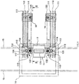
Fig. 1 is a top view showing a schematic structure of main portions in the major embodiment of the dual-roller continuous casting apparatus using the side seal plate transfer device in the present invention. -
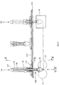
Fig. 2 is a view viewed along the arrow line of a section taken along line II-II inFig. 1 . -
Fig. 3 is a view viewed along the arrow line of a section taken along line III-III inFig. 2 . -
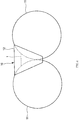
Fig. 4 is an illustration view of the melting pool. - Although the embodiments of the side seal plate transfer device and the dual-roller continuous casting apparatus using the same according to the present invention are described with reference to the drawings, the present invention is not limited to the following embodiments described with reference to the drawings.
- The major embodiment of the side seal plate transfer device and the dual-roller continuous casting apparatus using the same according to the present invention are described with reference to
Figs. 1-4 . - In
Figs. 1-4 , 1 is molten metal, 10 is a melting pool, 11 is a cooling roller, 12 is a side seal plate, 13 is a side seal plate pressing and attachment apparatus, 14 is a tundish, 15 is a moving guide rail, and 16 is a side seal plate preheating apparatus. - The
cooling rollers 11 are arranged in pairs opposite to and parallel to each other at the same height in a manner that the axial direction is oriented in the horizontal direction. Theside seal plates 12 are arranged in pairs between the pair of thecooling rollers 11 and on the both axial end sides of thecooling rollers 11 respectively, and themelting pool 10 is formed in a space formed between theside seal plates 12 and thecooling rollers 11. - The side seal plate pressing and
attachment apparatuses 13 are arranged in pairs between the pair of thecooling rollers 11 and on the both axial end sides of thecooling rollers 11 respectively. For the side seal plate pressing andattachment apparatus 13, by retracting ahydraulic cylinder 13b, a side sealplate support member 13a that detachably supports theside seal plate 12 deviates away from the end portion of thecooling roller 11, so as to be located at a detachment position P1 at which theside seal plates 12 are detached. In addition, for the side seal plate pressing andattachment apparatus 13, by advancing thehydraulic cylinder 13b, the side sealplate support member 13a can be located at a pressing and attachment position P2, at which theside seal plates 12 are pressed and attached to the end portion of thecooling rollers 11, so as to form themelting pool 10 between thecooling rollers 11 and theside seal plates 12. - The tundish 14 is disposed above the
melting pool 10 formed by thecooling rollers 11 and theside seal plates 12, and injects molten metal 1 into themelting pool 10. The movingguide rails 15 are disposed above themelting pool 10, and the tundish 14 moves along the axial direction of thecooling rollers 11. - That is, the tundish 14 is configured to be moved along the
moving guide rails 15 to-above themelting pool 10 when injecting the molten metal 1 into themelting pool 10, and is moved along the movingguide rails 15 to a standby position away from upper side of themelting pool 10 in the axial direction of thecooling rollers 11 when implementing the exchange of theside seal plates 12, and the like. - Therefore, the tundish 14 can be moved on the moving
guide rails 15 along the axial direction of thecooling rollers 11 to above themelting pool 10, and then inject the molten metal 1 into themelting pool 10; moreover, the tundish 14 can be moved in the direction perpendicular to the axial direction of thecooling rollers 11 to the standby position when implementing the exchange of theside seal plates 12, and the like. - The side seal
plate preheating apparatuses 16 are disposed at the following positions, that is, the positions away from the side seal plate pressing andattachment apparatuses 13 in the horizontal direction orthogonal to the axial direction of thecooling rollers 11, and the upper part of the side sealplate preheating apparatuses 16 is provided with an inlet/outlet for placing theside seal plates 12 into the inside or taking out theside seal plates 12 from the inside. In addition, preferably, the side sealplate preheating apparatuses 16 are set in such a manner that the height position (seeFig. 2 ) of theside seal plates 12 placed inside and the position in the axial direction of the cooling rollers 11 (seeFig. 1 ) are approximately consistent with the position of theside seal plates 12 held by the side sealplate support member 13a at the detachment position P1 of the side seal plate pressing andattachment apparatus 13. - Moreover, between the upper side of the side seal
plate preheating apparatuses 16 and the upper side of the side seal plate pressing andattachment apparatuses 13 disposed in a pairwise manner on both sides in the axial direction of thecooling rollers 11 respectively,guide rails 111, two as one set, are respectively disposed via abase 110 to connect them linearly. On the set of theguide rails 111, moving tables 112 that can slide along theguide rails 111 through asliding block 112a are respectively disposed across the twoguide rails 111. - On the moving tables 112,
columns 113 are vertically arranged respectively in the manner that the guide surface faces thecooling roller 11 side. On the guide surfaces of thecolumns 113, sliding tables 114 capable of sliding along the guide surfaces of thecolumns 113 in the vertical direction are respectively mounted. On the surface on thecooling roller 11 side of the sliding table 114, clamping apparatuses, namely aclamping apparatus 115, for clamping and holding theside seal plates 12 in a detachable manner are respectively mounted. - Inside the
columns 113,screw shafts 116 are respectively arranged in a rotatable manner, thescrew shafts 116 are screwed to the sliding tables 114 in the vertical direction towards the axial direction through the nut block (figure is omitted).Servo motors 117 are respectively mounted on the upper part of thecolumns 113, and the drive shafts of theservo motors 117 and the upper end of thescrew shafts 116 are connected. - In other words, when enabling the drive shafts of the
servo motors 117 to rotate so as to drive thescrew shafts 116 to rotate, the sliding tables 114 can slide in the vertical direction on the guide surfaces of thecolumns 113 by means of the nut blocks, and theclamping apparatuses 115 can be linearly moved up and down. - Between the set of the two
guide rails 111,racks 118 are respectively provided in the length direction along the entire length of theguide rails 111.Servo motors 120 are respectively arranged on the moving tables 112, and theservo motor 120 enables thedrive shaft 120a to penetrate through the moving table 112 in the vertical direction in a manner that the end of thedrive shaft 120a is disposed on the lower portion of the moving table 112. At the end of thedrive shafts 120a of theservo motors 120,pinions 119 meshed with theracks 118 are respectively mounted in the coaxial mode. - In other words, when enabling the
drive shaft 120a of theservo motor 120 to rotate and cause thepinion 119 to rotate, via thepinion 119 rotating and moving in the length direction of therack 118, the moving table 112 can be moved along theguide rails 111 through the slidingblock 112a, so that theclamping apparatus 115 can be switched between the position P3 above the inlet/outlet of the side sealplate preheating apparatuses 16 and the position P4 above the side sealplate support member 13a, wherein, the side sealplate support member 13a is disposed at the detachment position P1 of the side seal plate pressing andattachment apparatus 13. - In such an embodiment, the
guide rails 111, the moving table 112, therack 118, thepinion 119, theservo motor 120 and the like form thereciprocating moving apparatus 122; thecolumn 113, the sliding table 114, thescrew shaft 116, theservo motor 117 and the like form thelifting moving apparatus 123; thereciprocating moving apparatus 122, thelifting moving apparatus 123, and the like form moving apparatus; theclamping apparatus 115, the movingapparatuses plate transfer apparatus 121, and thecooling rollers 11, theside seal plates 12, the side seal plate pressing andattachment apparatuses 13, the side sealplate preheating apparatuses 16, the side sealplate transfer apparatuses 121 and the like form the dual-roller continuous casting apparatus. - In the dual-roller continuous casting apparatus using the side seal
plate transfer apparatuses 121 in the present embodiment, theside seal plates 12 are disposed on the both axial end sides of thecooling rollers 11 to form themelting pool 10. - Firstly, the
hydraulic cylinder 13b is contracted in the manner that the side sealplate support member 13a of the side seal plate pressing andattachment apparatus 13 is arranged at the detachment position P1, and theservo motor 120 is operated so as to position the moving table 112 in the manner that theclamping apparatus 115 is arranged at the position P3 above the side sealplate preheating apparatus 16. Then, theside seal plates 12 are placed inside the side sealplate preheating apparatuses 16, and the side sealplate preheating apparatuses 16 are caused to operate, so as to preheat theside seal plates 12. - Then, after the
side seal plates 12 are preheated to a range, for example, of 900-1300°C, the drive shafts of theservo motors 117 are enabled to rotate and drive thescrew shafts 116 to rotate, and the sliding tables 114 are driven to move downwards, so that the clampingapparatuses 115 can linearly descend in the vertical direction, and the clampingapparatuses 115 are placed into the side sealplate preheating apparatuses 16, so as to clamp theside seal plates 12 through the clampingapparatuses 115. Then, the drive shafts of theservo motors 117 are enabled to rotate reversely and drive thescrew shafts 116 to rotate reversely, and the sliding tables 114 are driven to move upwards, so that the clampingapparatuses 115 can linearly ascend in the vertical direction, so as to take theside seal plates 12 out of the side sealplate preheating apparatuses 16. - Next, the
drive shafts 120a of theservo motors 120 are enabled to rotate and drive thepinions 119 to rotate, and thepinions 119 move along theracks 118, so that the moving tables 112 can linearly move in the horizontal direction along theguide rails 111 through the slidingblocks 112a, and the clampingapparatuses 115 are disposed at the position P4 above the side sealplate support members 13a of the side seal plate pressing andattachment apparatuses 13. - Then, the drive shafts of the
servo motors 117 are enabled to rotate and drive thescrew shafts 116 to rotate, and the sliding tables 114 are driven to move downwards, so that the clampingapparatuses 115 can linearly descend in the vertical direction, and theside seal plates 12 are placed on the side sealplate support members 13a of the side seal plate pressing andattachment apparatuses 13, and then, the clampingapparatuses 115 release theside seal plates 12. Then, the drive shafts of theservo motors 117 are enabled to rotate reversely and drive thescrew shafts 116 to rotate reversely, and the sliding tables 114 are driven to move upwards, so that the clampingapparatuses 115 can linearly ascend in the vertical direction. - Next, the side seal
plate support members 13a of the side seal plate pressing andattachment apparatuses 13 are enabled to be located at the pressing and attachment position P2 by extending thehydraulic cylinder 13b, namely: theside seal plates 12 are pressed and attached to the end portions of thecooling rollers 11, so as to form themelting pool 10 between the coolingrollers 11 and theside seal plates 12. - In other words, in the present embodiment, the
side seal plates 12 can be transferred only in a linear moving mode under the condition that theside seal plates 12 are not rotationally moved between the side sealplate preheating apparatuses 16 and the side seal plate pressing andattachment apparatuses 13. - Therefore, in the present embodiment, due to the fact that the
side seal plates 12 can be moved in a state of being toward the same direction as the state of pressing the end portion of thecooling rollers 11, and the moving path of theside seal plates 12 can be shortened, theside seal plates 12 can be moved rapidly, and thus the heat release amount of theside seal plates 12 preheated to the high temperature during the moving can be inhibited. - Therefore, according to the present embodiment, the heat release amount of the preheated
side seal plates 12 disposed at the end portion position of thecooling rollers 11 can be inhibited, so as to reduce the waste of heat. - In addition, due to the fact that the
side seal plates 12 are not rotationally moved between the side sealplate preheating apparatuses 16 and the side seal plate pressing andattachment apparatuses 13, there is no need to ensure the space for rotation, and the space required for exchanging theside seal plates 12 can be reduced. - More concrete description is as follows. The set of
guide rails 111 are linearly arranged on the base 110 between the upper side of the side sealplate preheating apparatuses 16 and the upper side of the side seal plate pressing andattachment apparatuses 13. Thelifting moving apparatuses 123 and the clampingapparatuses 115 are arranged on the moving tables 112 moving on the set of the guide rails 111. - In this state, when the operator walks on the
base 110, the set of theguide rails 111 will enter the field of view of the operator, so that the operator can intuitively recognize the moving range of the moving tables 112. Therefore, due to the fact that the operator will avoid a contact accident with the moving tables 112 and the clampingapparatuses 115, the operator will move in a manner close to an unconscious feeling without entering the inner side and vicinity of the set of guide rails 111. Therefore, the safety of the operator can be ensured easily. - In addition, due to the fact that the side seal
plate preheating apparatuses 16 and the side seal plate pressing andattachment apparatuses 13 can be arranged separately from each other by using the set ofguide rails 111, the operation space necessary for maintaining the apparatuses can be ensured. Also, thelifting moving apparatuses 123 and the clampingapparatuses 115 can also move along with the moving tables 112, therefore, during the maintenance of the side seal plate pressing andattachment apparatuses 13 and the like, the moving tables 112 are used to move the clampingapparatuses 115 and the like to a position at which no obstruction will occur, which can also facilitate performing the maintenance operation safely. - In addition, due to the fact that the side seal
plate transfer apparatuses 121 are independently arranged on the axial both end sides of thecooling rollers 11 respectively in pairs, the exchange of theside seal plates 12 at one axial end side of thecooling rollers 11 and of theside seal plates 12 at the other end side can be implemented independently, and the side sealplate transfer apparatuses 121 of the same size can be applied regardless of the axial length of thecooling rollers 11. - Here, the openings 131-133 formed on the
base 110 and the devices around thebase 110 will be further described. - Although the
base 110 is arranged at a fixed height, and is further provided with devices, thebase 110 is also the space for the operator to move or operate in order to perform the inspection and the like of the devices. At a lower position relative to thebase 110, themelting pool 10, the coolingrollers 11, the side seal plate pressing andattachment apparatuses 13 and the side sealplate preheating apparatuses 16 are arranged. A pair ofguide rails 111 are disposed on thebase 110, when viewed from above, at the outer side of both end surfaces of thecooling rollers 11, the pair ofguide rails 111 extend linearly from the side seal plate pressing andattachment apparatuses 13 to the side sealplate preheating apparatuses 16 respectively. - The side seal
plate transfer apparatuses 121 are in one pair, and travel on the pair ofguide rails 111 respectively. The side sealplate transfer apparatuses 121 support theside seal plates 12 in a detachable manner, and transfer theside seal plates 12 between the side sealplate preheating apparatuses 16 and the side seal plate pressing andattachment apparatuses 13. - The
first opening 131 is formed on thebase 110 above themelting pool 10. Thetundish 14 is placed on the moving guide rail 15 (left side inFig. 1 ) arranged on thebase 110 and the moving guide rail 15 (right side inFig. 1 ) arranged on an upper side relative to the base 110 to move, until the position of thefirst opening 131. During the operation of the continuous casing apparatus, thetundish 14 moves downwards, and injects the molten metal 1 into themelting pool 10 from the lower portion of thetundish 14 through thefirst opening 131. - In addition, a pair of the
second openings 133 are formed on thebase 110. Thesecond openings 133 are located at a preset distance from theguide rails 111 towards the coolingrollers 11 side, and are arranged in a manner corresponding to the respective guide rails 111. Thesecond openings 133 are the paths for the side sealplate transfer apparatuses 121 to receive theside seal plates 12 from the side sealplate preheating apparatuses 16, or to transfer theside seal plates 12 to the side sealplate preheating apparatuses 16. - In addition, a pair of the
third openings 132 are formed on thebase 110. Thethird openings 132 are located at a preset distance from theguide rails 111 towards the coolingrollers 11 side, and are arranged in a manner corresponding to the respective guide rails 111. Thethird openings 132 are the paths for the side sealplate transfer apparatuses 121 to receive theside seal plates 12 from the side seal plate pressing andattachment apparatuses 13, or to transfer theside seal plates 12 to the side seal plate pressing andattachment apparatuses 13. - According to the structure, due to the fact that a quadrangular area surrounded by the first opening 131 (above a certain position of the melting pool 10) and the pair of
linear guide rails 111 exists on thebase 110, and relevant major devices are arranged under thebase 110, the area on the base 110 can be utilized by the operator to perform operation and inspection on themelting pool 10, the pressing andattachment apparatus 13 and the preheatingapparatus 16. - Therefore, the operator naturally walks carefully in the area, taking care not to place extra object, making it easier to ensure a safe space for operation. For example, due to the fact that under the condition of the following configuration, that is, the
second openings 133 and thethird openings 132 are formed at the outer side of the area enclosed by the pair ofguide rails 111, it is difficult to recognize the range of the operation area, and therefore, it is difficult to ensure the safety if no attention is given to the operator. - Further, due to the fact that the relevant major devices are arranged under the
base 110, a larger operation area on the base 110 can be ensured. - Further, due to the fact that the side seal
plate transfer apparatuses 121 travel on thelinear guide rails 111 arranged at the outer side relative to both end surfaces of thecooling rollers 11, the operation in the quadrangular area cannot be hindered, and it can rather be a general indication for recognizing the periphery of the area. - Further, due to the fact that the side seal
plate transfer apparatuses 121 travel on thelinear guide rails 111, and both thesecond openings 133 and thethird openings 132 are located at the same distance on the inner side of thelinear guide rails 111, also, when viewed from thelinear guide rails 111, thethird opening 132 is arranged at one side close to the coolingroller 11, so that the transfer distance of theside seal plates 12 can be shortened, and theside seal plates 12 can be rapidly transferred. - Moreover, due to the fact that the
third openings 132 are formed between thefirst opening 131 and theguide rails 111, and are located in line with thefirst opening 131 in the axial direction of thecooling rollers 11, it can be ensured that the operation area surrounded by thefirst opening 131, the pair of thesecond openings 133 and the pair of thethird openings 132 are relatively large, and easier to recognize the safe operation area. - Also, due to the fact that the area enclosed by the openings 131-133 is also an area between the pair of
guide rails 111, it is also easy to visibly recognize the area from the pair of guide rails 111. In addition, due to the fact that the side sealplate transfer apparatuses 121 travel on theguide rails 111, but do not travel in the area between the pair ofguide rails 111, there is no possibility of colliding with the operator. - A pair of sliding
plates 140 are respectively disposed on the pair of thesecond openings 133 and the pair of thethird openings 132, and perform opening or closing in a manner that horizontally move at the lower face side of thebase 110. The opening and closing of the slidingplates 140 will take thehydraulic cylinder 141 connected with the slidingplates 140 as a drive unit respectively. As long as the slidingplates 140 are light weighted, an pneumatic cylinder can be used. However, preferably, the slidingplates 140 has rigidity, in this case, due to accompanying weight, preferably, the drive unit is used as thehydraulic cylinder 141. - According to the structure, due to the fact that the
second openings 133 and thethird openings 132 are openings used only when theside seal plates 12 are transferred, and are not used in other time, a closed state thereof can be realized through the slidingplates 140 when not in use, so that the operation can be easily and safely performed on thebase 110 by the operator. - In addition,
respective guide rails 111 are composed of two guide rails. Therack 118 extending parallel to the guide rails 111 is arranged between the twoguide rails 111. The side sealplate transfer apparatus 121 comprises theclamping apparatus 115, thereciprocating moving apparatus 122 and thelifting moving apparatus 123. Theclamping apparatus 115 is provided with a mechanism for temporally clamping theside seal plate 12. Thereciprocating moving apparatus 122 is provided with apinion 119 and amotor 120, thepinion 119 are meshed with therack 118 and can move along the extending direction of therack 118, and themotor 120 drives thepinion 119. Thelifting moving apparatus 123 is a mechanism for enabling theclamping apparatus 115 to move up and down at the position separated from theguide rails 111 towards the coolingroller 11 side by a preset distance. - According to the structure, due to the fact that the formation of the quadrangular area surrounded by the
first opening 131 at which the lower part of thetundish 14 reaches and the pair ofguide rails 111 is added with the rack extending parallel to theguide rail 111, it is easier to recognize the situation that the quadrangular area appears on thebase 110, so as to easily ensure the safe space for operation. - In addition, due to the fact that the distance, separated from the
guide rails 111, of thelifting moving apparatus 123 at the position for clamping theside seal plates 12 at the side sealplate preheating apparatuses 16 is substantially the same as that at the position for releasing and transferring theside seal plates 12 at the side seal plate pressing andattachment apparatuses 13, the moving distance of theside seal plates 12 can be shortened, the side seal plates do not rotate, and theside seal plates 12 can be moved more rapidly. - Moreover, due to the fact that the clamping
apparatuses 115 are lifted by thelifting moving apparatuses 123 by penetrating through thesecond openings 133 or thethird openings 132, theside seal plates 12 can be safely and smoothly transferred from the side sealplate preheating apparatuses 16 to the side seal plate pressing andattachment apparatuses 13. - Furthermore, in the embodiments as described above, the moving tables 112 can be arranged in a manner that move relative to the
guide rails 111 through the slidingblocks 112a, however, as an alternative embodiment, for example, the following manner can also be used, that is, instead of the slidingblocks 112a, the moving tables 112 can be arranged in a manner that move relative to theguide rails 111 through wheels. - In addition, in the embodiments as described above, the following manner is used, that is, through the
racks 118, thepinions 119 and the like, the moving tables 112 can be sliding moved along theguide rails 111, however, as an alternative embodiment, for example, the following manner can also be used, that is, by means of an actuator such as a retractable hydraulic cylinder or a rotatable screw shaft and the like, the moving tables 112 can be linearly reciprocated along the guide rails 111. - Further, in the embodiments as described above, the following manner is used, that is, by means of the
screw shaft 116 and the like, the moving tables 114 can be sliding moved along thecolumns 113, however, as an alternative embodiment, for example, the following manner can also be used, that is, by means of the actuator such as a retractable hydraulic cylinder, or the racks and pinions and the like, the moving tables 114 can be moved up and down linearly along thecolumns 113. - Further, in the embodiments as described above, the following manner is used, that is, by means of the moving
guide rails 15, thetundish 14 is enabled to be moved in a horizontal direction to the standby position deviated from the upper side of themelting pool 10 toward the axial direction of thecooling rollers 11, however, as an alternative embodiment, for example, the following manner can also be used, that is, by means of a lifter, thetundish 14 is enabled to be moved in a vertical direction toward the standby position further deviated upward from the upper side of themelting pool 10. - In addition, under the condition that even the
tundish 14 is arranged above themelting pool 10, thetundish 14 does not interfere with the side sealplate transfer apparatuses 121, when the exchange of theside seal plates 12 is implemented, the content that thetundish 14 moves towards the standby position can also be omitted. -
- 1
- Molten metal;
- 10
- Melting pool;
- 11
- Cooling roller;
- 12
- Side seal plate;
- 13
- Side seal plate pressing and attachment apparatus;
- 13a
- Side seal plate support member;
- 13b
- Hydraulic cylinder;
- 14
- Tundish;
- 15
- Moving guide rail;
- 16
- Side seal plate preheating apparatus;
- 110
- Base;
- 111
- Guide rail;
- 112
- Moving table;
- 112a
- Sliding block;
- 113
- Column;
- 114
- Sliding table;
- 115
- Clamping apparatus;
- 116
- Screw shaft;
- 117
- Servo motor;
- 118
- Rack;
- 119
- Pinion;
- 120
- Servo motor;
- 120a
- Drive shaft;
- 121
- Side seal plate transfer device;
- 122
- Reciprocating moving apparatus;
- 123
- Lifting moving apparatus;
- 131
- First opening;
- 132
- Third opening;
- 133
- Second opening;
- 140
- Sliding plate;
- 141
- Hydraulic cylinder.
Claims (5)
- A side seal plate transfer device, comprising:a pair of side seal plate preheating apparatuses for receiving and heating side seal plates which are used in connection with end surfaces of a pair of cooling rollers constituting a melting pool of a continuous casting apparatus;a pair of side seal plate pressing and attachment apparatuses disposed opposite to the two end surfaces of the cooling rollers respectively and capable of assembling and disassembling the side seal plates, and enabling the side seal plates to be pressed and attached to the end surfaces of the cooling rollers,the side seal plate transfer device characterized by further comprising:a base, the melting pool, the cooling rollers, the side seal plate pressing and attachment apparatuses and the side seal plate preheating apparatuses being provided at positions closer to the lower side relative to the base;a pair of guide rails provided on the base, when viewed from above, at the outer side of the two end surfaces of the cooling rollers, extending linearly from the side seal plate pressing and attachment apparatuses to the side seal plate preheating apparatuses respectively;a pair of side seal plate transfer apparatuses, travelling on the respective guide rails, supporting the side seal plates in a detachable manner, and transferring the side seal plates between the side seal plate preheating apparatuses and the side seal plate pressing and attachment apparatuses;a first opening formed on the base above the melting pool;a pair of second openings, serving as paths for transferring the side seal plates from the side seal plate preheating apparatuses to the side seal plate transfer apparatuses, and formed on the base at a position where a preset distance is separated from the guide rails towards the cooling roller side;a pair of third openings, serving as paths for transferring the side seal plates from the side seal plate transfer apparatuses to the side seal plate pressing and attachment apparatuses, and formed on the base at a position where the preset distance is separated from the guide rails towards the cooling roller side.
- The side seal plate transfer device of claim 1, characterized in that,
the third openings are arranged between the first opening and the guide rails, and are located in line with the first opening in the axial direction of the cooling rollers. - The side seal plate transfer device of claim 1 or 2, characterized in that,
a pair of sliding plates are respectively disposed on the pair of the second openings and the pair of the third openings, and perform opening or closing in a manner that horizontally move at the lower face side of the base. - The side seal plate transfer device of any one of claims 1-3, characterized in that,
the respective guide rails are composed of two guide rails,
the side seal plate transfer device is provided with a rack which is arranged between the two guide rails and extends parallel to the guide rails,
the side seal plate transfer apparatus comprises a clamping apparatus, a reciprocating moving apparatus and a lifting moving apparatus,
the clamping apparatus comprises a mechanism for temporarily clamping the side seal plate,
the reciprocating moving apparatus comprises a pinion and a motor, the pinion is meshed with the rack and can move along the extension direction of the rack, the motor drives the pinion, and
the lifting moving apparatus comprises a mechanism for enabling the clamping apparatus to move up and down at a position where the preset distance is separated from the guide rails towards the cooling roller side. - The twin-roller continuous casting device of claim 4, characterized in that,
the clamping apparatus is lifted by the lifting moving apparatus in a manner that can penetrate through the second opening or the third opening.
Applications Claiming Priority (1)
| Application Number | Priority Date | Filing Date | Title |
|---|---|---|---|
| PCT/CN2016/112011 WO2018119553A1 (en) | 2016-12-26 | 2016-12-26 | Side seal plate transfer device |
Publications (3)
| Publication Number | Publication Date |
|---|---|
| EP3546088A1 true EP3546088A1 (en) | 2019-10-02 |
| EP3546088A4 EP3546088A4 (en) | 2019-11-13 |
| EP3546088B1 EP3546088B1 (en) | 2020-11-11 |
Family
ID=62706623
Family Applications (1)
| Application Number | Title | Priority Date | Filing Date |
|---|---|---|---|
| EP16925025.5A Active EP3546088B1 (en) | 2016-12-26 | 2016-12-26 | Side seal plate transfer device |
Country Status (5)
| Country | Link |
|---|---|
| EP (1) | EP3546088B1 (en) |
| JP (1) | JP6710341B2 (en) |
| CN (1) | CN110114169B (en) |
| RU (1) | RU2719240C1 (en) |
| WO (1) | WO2018119553A1 (en) |
Families Citing this family (1)
| Publication number | Priority date | Publication date | Assignee | Title |
|---|---|---|---|---|
| CN118003533B (en) * | 2024-03-15 | 2024-07-12 | 江苏有康健身游乐设备有限公司 | Plastic injection molding equipment and molding method thereof |
Family Cites Families (8)
| Publication number | Priority date | Publication date | Assignee | Title |
|---|---|---|---|---|
| JPH0755357B2 (en) * | 1992-02-12 | 1995-06-14 | 三菱重工業株式会社 | Side weir exchange device of twin-drum type continuous casting machine |
| US7134481B2 (en) * | 2003-11-11 | 2006-11-14 | Ishikawajima-Harima Heavy Industries Co., Ltd. | Preheating member changer of dual roll casting apparatus |
| US7191819B2 (en) * | 2004-12-07 | 2007-03-20 | Nucor Corporation | Continuously casting steel strip |
| US7556084B2 (en) * | 2006-03-24 | 2009-07-07 | Nucor Corporation | Long wear side dams |
| CN201543794U (en) * | 2009-10-27 | 2010-08-11 | 宝山钢铁股份有限公司 | Lifting link type flow distribution device |
| CN102198495B (en) * | 2010-03-26 | 2013-05-29 | 宝山钢铁股份有限公司 | Method for controlling side seal of twin roll thin strip casting and device |
| CN103100674A (en) * | 2012-11-29 | 2013-05-15 | 一重集团大连设计研究院有限公司 | Combination-type side sealing device of horizontal double-roller continuous casting machine |
| CN104972081B (en) * | 2015-07-14 | 2017-03-01 | 燕山大学 | A kind of pre-heating mean overall to thin-belt casting rolling current distribution device and side seal board and device |
-
2016
- 2016-12-26 EP EP16925025.5A patent/EP3546088B1/en active Active
- 2016-12-26 JP JP2019534735A patent/JP6710341B2/en active Active
- 2016-12-26 RU RU2019119340A patent/RU2719240C1/en active
- 2016-12-26 WO PCT/CN2016/112011 patent/WO2018119553A1/en not_active Ceased
- 2016-12-26 CN CN201680091711.1A patent/CN110114169B/en active Active
Also Published As
| Publication number | Publication date |
|---|---|
| RU2719240C1 (en) | 2020-04-17 |
| EP3546088B1 (en) | 2020-11-11 |
| WO2018119553A1 (en) | 2018-07-05 |
| JP2020501915A (en) | 2020-01-23 |
| EP3546088A4 (en) | 2019-11-13 |
| CN110114169A (en) | 2019-08-09 |
| CN110114169B (en) | 2021-03-16 |
| JP6710341B2 (en) | 2020-06-17 |
Similar Documents
| Publication | Publication Date | Title |
|---|---|---|
| JP5331194B2 (en) | Strip casting equipment for quick set-up and replacement of casting rolls | |
| KR100210519B1 (en) | Casting device and casting method of metal strip | |
| EP3546088B1 (en) | Side seal plate transfer device | |
| JP5688600B2 (en) | Winding conductor supply device | |
| CN105415483A (en) | Mobile casting platform with protection function | |
| EP2980229B1 (en) | Apparatus for thermal treatments of metals, particularly for hardening and tempering steel | |
| KR101756457B1 (en) | Skull removal and clamping equipment of tundish | |
| JPH081306A (en) | Precision casting equipment with lock gate | |
| KR200181433Y1 (en) | Roll exchange device for horizontal type anealing furnace | |
| CN103194575B (en) | Steel billet anti-tipping device and control method during tapping and loading process of hot rolling heating furnace | |
| KR20160092619A (en) | Casting equipment of vertical type and method for casting using it | |
| JP6548833B2 (en) | Casting facility and casting method | |
| KR101344320B1 (en) | Extractor for heating furnace | |
| CN110405190B (en) | Ladle transfer device | |
| CN105925772B (en) | A kind of fast transfer device suitable for vacuum water quenching system | |
| DE10156966C2 (en) | Electro-slag remelting plant with a mold, a hood and a motor-driven electrode rod | |
| CN202729979U (en) | Glass liquation transfer car | |
| KR20130063561A (en) | Comprehensive mould turning apparatus for radwaste melting decontamination and mould turning method thereof | |
| KR100815700B1 (en) | Dummy slab take out device of furnace | |
| CN204504204U (en) | Multistation is in length and breadth to covering/uncovering system | |
| CN104141032B (en) | A kind of cylinder part continous heat processing method and transfer device | |
| CN121761623A (en) | Waste copper melting heat preservation recovery device with temperature monitoring function | |
| KR101357556B1 (en) | Extractor for heating furnace | |
| KR19990023046U (en) | Slab taking out device | |
| KR19990054876A (en) | Aluminum Gravity Casting and Extraction Device |
Legal Events
| Date | Code | Title | Description |
|---|---|---|---|
| STAA | Information on the status of an ep patent application or granted ep patent |
Free format text: STATUS: THE INTERNATIONAL PUBLICATION HAS BEEN MADE |
|
| PUAI | Public reference made under article 153(3) epc to a published international application that has entered the european phase |
Free format text: ORIGINAL CODE: 0009012 |
|
| STAA | Information on the status of an ep patent application or granted ep patent |
Free format text: STATUS: REQUEST FOR EXAMINATION WAS MADE |
|
| 17P | Request for examination filed |
Effective date: 20190624 |
|
| AK | Designated contracting states |
Kind code of ref document: A1 Designated state(s): AL AT BE BG CH CY CZ DE DK EE ES FI FR GB GR HR HU IE IS IT LI LT LU LV MC MK MT NL NO PL PT RO RS SE SI SK SM TR |
|
| AX | Request for extension of the european patent |
Extension state: BA ME |
|
| A4 | Supplementary search report drawn up and despatched |
Effective date: 20191010 |
|
| RIC1 | Information provided on ipc code assigned before grant |
Ipc: B22D 11/06 20060101AFI20191004BHEP Ipc: B22D 33/00 20060101ALI20191004BHEP |
|
| DAV | Request for validation of the european patent (deleted) | ||
| DAX | Request for extension of the european patent (deleted) | ||
| STAA | Information on the status of an ep patent application or granted ep patent |
Free format text: STATUS: EXAMINATION IS IN PROGRESS |
|
| 17Q | First examination report despatched |
Effective date: 20200417 |
|
| GRAP | Despatch of communication of intention to grant a patent |
Free format text: ORIGINAL CODE: EPIDOSNIGR1 |
|
| STAA | Information on the status of an ep patent application or granted ep patent |
Free format text: STATUS: GRANT OF PATENT IS INTENDED |
|
| INTG | Intention to grant announced |
Effective date: 20200629 |
|
| GRAS | Grant fee paid |
Free format text: ORIGINAL CODE: EPIDOSNIGR3 |
|
| GRAA | (expected) grant |
Free format text: ORIGINAL CODE: 0009210 |
|
| STAA | Information on the status of an ep patent application or granted ep patent |
Free format text: STATUS: THE PATENT HAS BEEN GRANTED |
|
| AK | Designated contracting states |
Kind code of ref document: B1 Designated state(s): AL AT BE BG CH CY CZ DE DK EE ES FI FR GB GR HR HU IE IS IT LI LT LU LV MC MK MT NL NO PL PT RO RS SE SI SK SM TR |
|
| REG | Reference to a national code |
Ref country code: GB Ref legal event code: FG4D |
|
| REG | Reference to a national code |
Ref country code: CH Ref legal event code: EP |
|
| REG | Reference to a national code |
Ref country code: AT Ref legal event code: REF Ref document number: 1332967 Country of ref document: AT Kind code of ref document: T Effective date: 20201115 |
|
| REG | Reference to a national code |
Ref country code: DE Ref legal event code: R096 Ref document number: 602016047906 Country of ref document: DE |
|
| REG | Reference to a national code |
Ref country code: IE Ref legal event code: FG4D |
|
| REG | Reference to a national code |
Ref country code: NL Ref legal event code: MP Effective date: 20201111 |
|
| REG | Reference to a national code |
Ref country code: AT Ref legal event code: MK05 Ref document number: 1332967 Country of ref document: AT Kind code of ref document: T Effective date: 20201111 |
|
| PG25 | Lapsed in a contracting state [announced via postgrant information from national office to epo] |
Ref country code: NO Free format text: LAPSE BECAUSE OF FAILURE TO SUBMIT A TRANSLATION OF THE DESCRIPTION OR TO PAY THE FEE WITHIN THE PRESCRIBED TIME-LIMIT Effective date: 20210211 Ref country code: PT Free format text: LAPSE BECAUSE OF FAILURE TO SUBMIT A TRANSLATION OF THE DESCRIPTION OR TO PAY THE FEE WITHIN THE PRESCRIBED TIME-LIMIT Effective date: 20210311 Ref country code: RS Free format text: LAPSE BECAUSE OF FAILURE TO SUBMIT A TRANSLATION OF THE DESCRIPTION OR TO PAY THE FEE WITHIN THE PRESCRIBED TIME-LIMIT Effective date: 20201111 Ref country code: GR Free format text: LAPSE BECAUSE OF FAILURE TO SUBMIT A TRANSLATION OF THE DESCRIPTION OR TO PAY THE FEE WITHIN THE PRESCRIBED TIME-LIMIT Effective date: 20210212 Ref country code: FI Free format text: LAPSE BECAUSE OF FAILURE TO SUBMIT A TRANSLATION OF THE DESCRIPTION OR TO PAY THE FEE WITHIN THE PRESCRIBED TIME-LIMIT Effective date: 20201111 |
|
| PG25 | Lapsed in a contracting state [announced via postgrant information from national office to epo] |
Ref country code: SE Free format text: LAPSE BECAUSE OF FAILURE TO SUBMIT A TRANSLATION OF THE DESCRIPTION OR TO PAY THE FEE WITHIN THE PRESCRIBED TIME-LIMIT Effective date: 20201111 Ref country code: BG Free format text: LAPSE BECAUSE OF FAILURE TO SUBMIT A TRANSLATION OF THE DESCRIPTION OR TO PAY THE FEE WITHIN THE PRESCRIBED TIME-LIMIT Effective date: 20210211 Ref country code: PL Free format text: LAPSE BECAUSE OF FAILURE TO SUBMIT A TRANSLATION OF THE DESCRIPTION OR TO PAY THE FEE WITHIN THE PRESCRIBED TIME-LIMIT Effective date: 20201111 Ref country code: LV Free format text: LAPSE BECAUSE OF FAILURE TO SUBMIT A TRANSLATION OF THE DESCRIPTION OR TO PAY THE FEE WITHIN THE PRESCRIBED TIME-LIMIT Effective date: 20201111 Ref country code: IS Free format text: LAPSE BECAUSE OF FAILURE TO SUBMIT A TRANSLATION OF THE DESCRIPTION OR TO PAY THE FEE WITHIN THE PRESCRIBED TIME-LIMIT Effective date: 20210311 Ref country code: AT Free format text: LAPSE BECAUSE OF FAILURE TO SUBMIT A TRANSLATION OF THE DESCRIPTION OR TO PAY THE FEE WITHIN THE PRESCRIBED TIME-LIMIT Effective date: 20201111 |
|
| REG | Reference to a national code |
Ref country code: LT Ref legal event code: MG9D |
|
| PG25 | Lapsed in a contracting state [announced via postgrant information from national office to epo] |
Ref country code: HR Free format text: LAPSE BECAUSE OF FAILURE TO SUBMIT A TRANSLATION OF THE DESCRIPTION OR TO PAY THE FEE WITHIN THE PRESCRIBED TIME-LIMIT Effective date: 20201111 |
|
| PG25 | Lapsed in a contracting state [announced via postgrant information from national office to epo] |
Ref country code: RO Free format text: LAPSE BECAUSE OF FAILURE TO SUBMIT A TRANSLATION OF THE DESCRIPTION OR TO PAY THE FEE WITHIN THE PRESCRIBED TIME-LIMIT Effective date: 20201111 Ref country code: SK Free format text: LAPSE BECAUSE OF FAILURE TO SUBMIT A TRANSLATION OF THE DESCRIPTION OR TO PAY THE FEE WITHIN THE PRESCRIBED TIME-LIMIT Effective date: 20201111 Ref country code: CZ Free format text: LAPSE BECAUSE OF FAILURE TO SUBMIT A TRANSLATION OF THE DESCRIPTION OR TO PAY THE FEE WITHIN THE PRESCRIBED TIME-LIMIT Effective date: 20201111 Ref country code: EE Free format text: LAPSE BECAUSE OF FAILURE TO SUBMIT A TRANSLATION OF THE DESCRIPTION OR TO PAY THE FEE WITHIN THE PRESCRIBED TIME-LIMIT Effective date: 20201111 Ref country code: SM Free format text: LAPSE BECAUSE OF FAILURE TO SUBMIT A TRANSLATION OF THE DESCRIPTION OR TO PAY THE FEE WITHIN THE PRESCRIBED TIME-LIMIT Effective date: 20201111 Ref country code: LT Free format text: LAPSE BECAUSE OF FAILURE TO SUBMIT A TRANSLATION OF THE DESCRIPTION OR TO PAY THE FEE WITHIN THE PRESCRIBED TIME-LIMIT Effective date: 20201111 |
|
| REG | Reference to a national code |
Ref country code: CH Ref legal event code: PL |
|
| REG | Reference to a national code |
Ref country code: DE Ref legal event code: R097 Ref document number: 602016047906 Country of ref document: DE |
|
| PG25 | Lapsed in a contracting state [announced via postgrant information from national office to epo] |
Ref country code: DK Free format text: LAPSE BECAUSE OF FAILURE TO SUBMIT A TRANSLATION OF THE DESCRIPTION OR TO PAY THE FEE WITHIN THE PRESCRIBED TIME-LIMIT Effective date: 20201111 Ref country code: MC Free format text: LAPSE BECAUSE OF FAILURE TO SUBMIT A TRANSLATION OF THE DESCRIPTION OR TO PAY THE FEE WITHIN THE PRESCRIBED TIME-LIMIT Effective date: 20201111 |
|
| REG | Reference to a national code |
Ref country code: BE Ref legal event code: MM Effective date: 20201231 |
|
| PLBE | No opposition filed within time limit |
Free format text: ORIGINAL CODE: 0009261 |
|
| STAA | Information on the status of an ep patent application or granted ep patent |
Free format text: STATUS: NO OPPOSITION FILED WITHIN TIME LIMIT |
|
| 26N | No opposition filed |
Effective date: 20210812 |
|
| GBPC | Gb: european patent ceased through non-payment of renewal fee |
Effective date: 20210211 |
|
| PG25 | Lapsed in a contracting state [announced via postgrant information from national office to epo] |
Ref country code: FR Free format text: LAPSE BECAUSE OF NON-PAYMENT OF DUE FEES Effective date: 20210111 Ref country code: LU Free format text: LAPSE BECAUSE OF NON-PAYMENT OF DUE FEES Effective date: 20201226 Ref country code: NL Free format text: LAPSE BECAUSE OF FAILURE TO SUBMIT A TRANSLATION OF THE DESCRIPTION OR TO PAY THE FEE WITHIN THE PRESCRIBED TIME-LIMIT Effective date: 20201111 Ref country code: AL Free format text: LAPSE BECAUSE OF FAILURE TO SUBMIT A TRANSLATION OF THE DESCRIPTION OR TO PAY THE FEE WITHIN THE PRESCRIBED TIME-LIMIT Effective date: 20201111 Ref country code: IE Free format text: LAPSE BECAUSE OF NON-PAYMENT OF DUE FEES Effective date: 20201226 |
|
| PG25 | Lapsed in a contracting state [announced via postgrant information from national office to epo] |
Ref country code: SI Free format text: LAPSE BECAUSE OF FAILURE TO SUBMIT A TRANSLATION OF THE DESCRIPTION OR TO PAY THE FEE WITHIN THE PRESCRIBED TIME-LIMIT Effective date: 20201111 Ref country code: CH Free format text: LAPSE BECAUSE OF NON-PAYMENT OF DUE FEES Effective date: 20201231 Ref country code: LI Free format text: LAPSE BECAUSE OF NON-PAYMENT OF DUE FEES Effective date: 20201231 |
|
| PG25 | Lapsed in a contracting state [announced via postgrant information from national office to epo] |
Ref country code: GB Free format text: LAPSE BECAUSE OF NON-PAYMENT OF DUE FEES Effective date: 20210211 Ref country code: ES Free format text: LAPSE BECAUSE OF FAILURE TO SUBMIT A TRANSLATION OF THE DESCRIPTION OR TO PAY THE FEE WITHIN THE PRESCRIBED TIME-LIMIT Effective date: 20201111 |
|
| PG25 | Lapsed in a contracting state [announced via postgrant information from national office to epo] |
Ref country code: IS Free format text: LAPSE BECAUSE OF FAILURE TO SUBMIT A TRANSLATION OF THE DESCRIPTION OR TO PAY THE FEE WITHIN THE PRESCRIBED TIME-LIMIT Effective date: 20210311 Ref country code: TR Free format text: LAPSE BECAUSE OF FAILURE TO SUBMIT A TRANSLATION OF THE DESCRIPTION OR TO PAY THE FEE WITHIN THE PRESCRIBED TIME-LIMIT Effective date: 20201111 Ref country code: MT Free format text: LAPSE BECAUSE OF FAILURE TO SUBMIT A TRANSLATION OF THE DESCRIPTION OR TO PAY THE FEE WITHIN THE PRESCRIBED TIME-LIMIT Effective date: 20201111 Ref country code: CY Free format text: LAPSE BECAUSE OF FAILURE TO SUBMIT A TRANSLATION OF THE DESCRIPTION OR TO PAY THE FEE WITHIN THE PRESCRIBED TIME-LIMIT Effective date: 20201111 |
|
| PG25 | Lapsed in a contracting state [announced via postgrant information from national office to epo] |
Ref country code: MK Free format text: LAPSE BECAUSE OF FAILURE TO SUBMIT A TRANSLATION OF THE DESCRIPTION OR TO PAY THE FEE WITHIN THE PRESCRIBED TIME-LIMIT Effective date: 20201111 |
|
| PG25 | Lapsed in a contracting state [announced via postgrant information from national office to epo] |
Ref country code: BE Free format text: LAPSE BECAUSE OF NON-PAYMENT OF DUE FEES Effective date: 20201231 |
|
| PGFP | Annual fee paid to national office [announced via postgrant information from national office to epo] |
Ref country code: IT Payment date: 20251126 Year of fee payment: 10 |
|
| PGFP | Annual fee paid to national office [announced via postgrant information from national office to epo] |
Ref country code: DE Payment date: 20260225 Year of fee payment: 10 |