EP3545890A1 - Segmented balloon catheter - Google Patents
Segmented balloon catheter Download PDFInfo
- Publication number
- EP3545890A1 EP3545890A1 EP18215127.4A EP18215127A EP3545890A1 EP 3545890 A1 EP3545890 A1 EP 3545890A1 EP 18215127 A EP18215127 A EP 18215127A EP 3545890 A1 EP3545890 A1 EP 3545890A1
- Authority
- EP
- European Patent Office
- Prior art keywords
- sectors
- fluid
- catheter
- inflatable
- valves
- Prior art date
- Legal status (The legal status is an assumption and is not a legal conclusion. Google has not performed a legal analysis and makes no representation as to the accuracy of the status listed.)
- Withdrawn
Links
Images


Classifications
-
- A—HUMAN NECESSITIES
- A61—MEDICAL OR VETERINARY SCIENCE; HYGIENE
- A61B—DIAGNOSIS; SURGERY; IDENTIFICATION
- A61B18/00—Surgical instruments, devices or methods for transferring non-mechanical forms of energy to or from the body
- A61B18/04—Surgical instruments, devices or methods for transferring non-mechanical forms of energy to or from the body by heating
- A61B18/12—Surgical instruments, devices or methods for transferring non-mechanical forms of energy to or from the body by heating by passing a current through the tissue to be heated, e.g. high-frequency current
- A61B18/14—Probes or electrodes therefor
- A61B18/1492—Probes or electrodes therefor having a flexible, catheter-like structure, e.g. for heart ablation
-
- A—HUMAN NECESSITIES
- A61—MEDICAL OR VETERINARY SCIENCE; HYGIENE
- A61B—DIAGNOSIS; SURGERY; IDENTIFICATION
- A61B5/00—Measuring for diagnostic purposes; Identification of persons
- A61B5/24—Detecting, measuring or recording bioelectric or biomagnetic signals of the body or parts thereof
- A61B5/25—Bioelectric electrodes therefor
- A61B5/251—Means for maintaining electrode contact with the body
-
- A—HUMAN NECESSITIES
- A61—MEDICAL OR VETERINARY SCIENCE; HYGIENE
- A61B—DIAGNOSIS; SURGERY; IDENTIFICATION
- A61B5/00—Measuring for diagnostic purposes; Identification of persons
- A61B5/24—Detecting, measuring or recording bioelectric or biomagnetic signals of the body or parts thereof
- A61B5/25—Bioelectric electrodes therefor
- A61B5/279—Bioelectric electrodes therefor specially adapted for particular uses
- A61B5/28—Bioelectric electrodes therefor specially adapted for particular uses for electrocardiography [ECG]
-
- A—HUMAN NECESSITIES
- A61—MEDICAL OR VETERINARY SCIENCE; HYGIENE
- A61B—DIAGNOSIS; SURGERY; IDENTIFICATION
- A61B5/00—Measuring for diagnostic purposes; Identification of persons
- A61B5/24—Detecting, measuring or recording bioelectric or biomagnetic signals of the body or parts thereof
- A61B5/25—Bioelectric electrodes therefor
- A61B5/279—Bioelectric electrodes therefor specially adapted for particular uses
- A61B5/28—Bioelectric electrodes therefor specially adapted for particular uses for electrocardiography [ECG]
- A61B5/283—Invasive
- A61B5/287—Holders for multiple electrodes, e.g. electrode catheters for electrophysiological study [EPS]
-
- A—HUMAN NECESSITIES
- A61—MEDICAL OR VETERINARY SCIENCE; HYGIENE
- A61M—DEVICES FOR INTRODUCING MEDIA INTO, OR ONTO, THE BODY; DEVICES FOR TRANSDUCING BODY MEDIA OR FOR TAKING MEDIA FROM THE BODY; DEVICES FOR PRODUCING OR ENDING SLEEP OR STUPOR
- A61M25/00—Catheters; Hollow probes
- A61M25/10—Balloon catheters
- A61M25/1018—Balloon inflating or inflation-control devices
- A61M25/10184—Means for controlling or monitoring inflation or deflation
- A61M25/10185—Valves
-
- A—HUMAN NECESSITIES
- A61—MEDICAL OR VETERINARY SCIENCE; HYGIENE
- A61B—DIAGNOSIS; SURGERY; IDENTIFICATION
- A61B18/00—Surgical instruments, devices or methods for transferring non-mechanical forms of energy to or from the body
- A61B18/04—Surgical instruments, devices or methods for transferring non-mechanical forms of energy to or from the body by heating
- A61B18/12—Surgical instruments, devices or methods for transferring non-mechanical forms of energy to or from the body by heating by passing a current through the tissue to be heated, e.g. high-frequency current
- A61B18/1206—Generators therefor
-
- A—HUMAN NECESSITIES
- A61—MEDICAL OR VETERINARY SCIENCE; HYGIENE
- A61B—DIAGNOSIS; SURGERY; IDENTIFICATION
- A61B18/00—Surgical instruments, devices or methods for transferring non-mechanical forms of energy to or from the body
- A61B2018/00005—Cooling or heating of the probe or tissue immediately surrounding the probe
- A61B2018/00011—Cooling or heating of the probe or tissue immediately surrounding the probe with fluids
- A61B2018/00029—Cooling or heating of the probe or tissue immediately surrounding the probe with fluids open
-
- A—HUMAN NECESSITIES
- A61—MEDICAL OR VETERINARY SCIENCE; HYGIENE
- A61B—DIAGNOSIS; SURGERY; IDENTIFICATION
- A61B18/00—Surgical instruments, devices or methods for transferring non-mechanical forms of energy to or from the body
- A61B2018/00053—Mechanical features of the instrument of device
- A61B2018/00059—Material properties
- A61B2018/00065—Material properties porous
-
- A—HUMAN NECESSITIES
- A61—MEDICAL OR VETERINARY SCIENCE; HYGIENE
- A61B—DIAGNOSIS; SURGERY; IDENTIFICATION
- A61B18/00—Surgical instruments, devices or methods for transferring non-mechanical forms of energy to or from the body
- A61B2018/00053—Mechanical features of the instrument of device
- A61B2018/0016—Energy applicators arranged in a two- or three dimensional array
-
- A—HUMAN NECESSITIES
- A61—MEDICAL OR VETERINARY SCIENCE; HYGIENE
- A61B—DIAGNOSIS; SURGERY; IDENTIFICATION
- A61B18/00—Surgical instruments, devices or methods for transferring non-mechanical forms of energy to or from the body
- A61B2018/00053—Mechanical features of the instrument of device
- A61B2018/00214—Expandable means emitting energy, e.g. by elements carried thereon
- A61B2018/0022—Balloons
-
- A—HUMAN NECESSITIES
- A61—MEDICAL OR VETERINARY SCIENCE; HYGIENE
- A61B—DIAGNOSIS; SURGERY; IDENTIFICATION
- A61B18/00—Surgical instruments, devices or methods for transferring non-mechanical forms of energy to or from the body
- A61B2018/00053—Mechanical features of the instrument of device
- A61B2018/00214—Expandable means emitting energy, e.g. by elements carried thereon
- A61B2018/0022—Balloons
- A61B2018/0025—Multiple balloons
- A61B2018/00261—Multiple balloons arranged in a line
-
- A—HUMAN NECESSITIES
- A61—MEDICAL OR VETERINARY SCIENCE; HYGIENE
- A61B—DIAGNOSIS; SURGERY; IDENTIFICATION
- A61B18/00—Surgical instruments, devices or methods for transferring non-mechanical forms of energy to or from the body
- A61B2018/00053—Mechanical features of the instrument of device
- A61B2018/00214—Expandable means emitting energy, e.g. by elements carried thereon
- A61B2018/00267—Expandable means emitting energy, e.g. by elements carried thereon having a basket shaped structure
-
- A—HUMAN NECESSITIES
- A61—MEDICAL OR VETERINARY SCIENCE; HYGIENE
- A61B—DIAGNOSIS; SURGERY; IDENTIFICATION
- A61B18/00—Surgical instruments, devices or methods for transferring non-mechanical forms of energy to or from the body
- A61B2018/00315—Surgical instruments, devices or methods for transferring non-mechanical forms of energy to or from the body for treatment of particular body parts
- A61B2018/00345—Vascular system
- A61B2018/00351—Heart
-
- A—HUMAN NECESSITIES
- A61—MEDICAL OR VETERINARY SCIENCE; HYGIENE
- A61B—DIAGNOSIS; SURGERY; IDENTIFICATION
- A61B18/00—Surgical instruments, devices or methods for transferring non-mechanical forms of energy to or from the body
- A61B2018/00315—Surgical instruments, devices or methods for transferring non-mechanical forms of energy to or from the body for treatment of particular body parts
- A61B2018/00345—Vascular system
- A61B2018/00351—Heart
- A61B2018/00357—Endocardium
-
- A—HUMAN NECESSITIES
- A61—MEDICAL OR VETERINARY SCIENCE; HYGIENE
- A61B—DIAGNOSIS; SURGERY; IDENTIFICATION
- A61B18/00—Surgical instruments, devices or methods for transferring non-mechanical forms of energy to or from the body
- A61B2018/00571—Surgical instruments, devices or methods for transferring non-mechanical forms of energy to or from the body for achieving a particular surgical effect
- A61B2018/00577—Ablation
Definitions
- This invention relates generally to methods and devices for invasive medical treatment. More particularly, this invention relates to improvements in catheters.
- Cardiac arrhythmias such as atrial fibrillation, occur when regions of cardiac tissue abnormally conduct electric signals to adjacent tissue, thereby disrupting the normal cardiac cycle and causing asynchronous rhythm.
- Procedures for treating arrhythmia include surgically disrupting the origin of the signals causing the arrhythmia, as well as disrupting the conducting pathway for such signals.
- By selectively ablating cardiac tissue by application of energy via a catheter it is sometimes possible to cease or modify the propagation of unwanted electrical signals from one portion of the heart to another.
- the ablation process destroys the unwanted electrical pathways by formation of non-conducting lesions.
- the catheter has a balloon that may be expanded at some portions along its length through inflation.
- the catheter may have one or more differently compliant sections along its length, or may have a generally noncompliant body with one or more separate compliant portions overlying it.
- the compliant portions may be separately inflated to create, in one section of the catheter an expanded disk-like configuration with a circular, somewhat planar surface that is oriented orthogonally to the direction of the guide wire and facing in a distal direction.
- the catheter bears one or more RF electrodes that are capable of conducting RF energy and may be positioned on the surface of the balloon such that they take a circular configuration on the planar surface.
- a medical apparatus including a catheter having an elongated shaft and a distal portion.
- the distal portion includes an inflatable assembly, wherein the inflatable assembly includes a containment chamber, an axial core and a plurality of longitudinally oriented partitions extending from the axial core to the wall of the chamber to divide the containment chamber into at least four inflatable sectors.
- the sectors are externally delimited by respective bounding portions of the outer surface. Hydraulic valves are connected to respective sectors to enable selective inflation of the sectors by a fluid when the valves are connected to a source of the fluid, and at least one surface electrode is mounted on each of the bounding portions.
- the apparatus may include a tip electrode disposed on the catheter distal to the inflatable assembly.
- the outer surface has perforations formed therethrough for egress of the fluid from the containment chamber.
- the apparatus may include a control processor operative to control the valves.
- the at least one surface electrode is deformable when their respective sectors inflate and deflate.
- a method of catheterization which is carried out by introducing a catheter into a heart chamber of a subject.
- the distal portion of the catheter includes an inflatable assembly.
- the inflatable assembly includes a containment chamber, an axial core and a plurality of longitudinally oriented partitions extending from the axial core to the wall of the chamber to divide the containment chamber into at least four inflatable sectors.
- the sectors are externally delimited by respective bounding portions of the outer surface. Hydraulic valves are connected to respective sectors to enable selective inflation of the sectors by a fluid when the valves are connected to a source of the fluid, and at least one surface electrode is mounted on each of the bounding portions.
- the method is further carried out by inflating a selected one of the pairs of the sectors sufficiently to stably press the outer surface of the pairs of the inflated sectors against the walls of the heart chamber while avoiding inflation of others of the sectors, wherein the at least one surface electrode of each sector of the selected pair contacts the walls of the heart chamber.
- Another aspect of the method is performed after inflating the selected pair of sector by measuring electrical potentials from the at least one surface electrode of the sectors of the selected pair.
- the method may include passing an electric current through at least one surface electrode to ablate a portion of the walls of the heart chamber.
- One aspect of the method is performed after inflating the selected pair of sectors by deflating the selected pair of the sectors, and thereafter inflating another one of the pairs.
- the outer surface has perforations formed therethrough, wherein inflating comprises flowing the fluid through the valves into the selected pairs of the sectors.
- the method further includes controlling the valves to admit the fluid into the selected pair and to exclude the fluid from sectors other than the selected pair, and cooling a surface electrode of the selected pair during ablation of the selected pair by egressing the fluid from the containment chamber via the perforations.
- the members of the selected pair of the sectors are inflated concurrently.
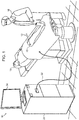
- Fig. 1 is a schematic, pictorial illustration of a vascular catheterization system 10 in accordance with an embodiment of the present invention.
- Use of the system 10 involves inserting a catheter 12 into the body of a subject 14 at an insertion point 30, for example a femoral artery or vein; thence into an internal body cavity, such as a heart chamber.
- the catheter 12 is used for diagnostic or therapeutic treatment performed by a medical practitioner 16, such as mapping electrical potentials in the heart or performing ablation of heart tissue.
- the catheter 12 may alternatively be used for other purposes, by itself or in conjunction with other treatment devices.
- control unit 26 which contains processors for data reported by signals from sensors in the catheter 12, e.g., via a cable 32.
- the control unit 26 may include an ablator power generator, irrigation pump and electrocardiographic circuitry. Events and data reported to the control unit 26 may be displayed on a monitor 34.
- the control unit 26 need not include position-locating circuitry to track the location and orientation of the catheter 12 in the heart and elsewhere in the body of the subject 14.
- the catheter 12 typically contains hydraulic lines to transfer fluid from the irrigation pump via the catheter's handle to the distal portion of the catheter 12 as explained below. The hydraulic connection to the pump is not shown in Fig. 1 in order to preserve clarity of illustration.
- Fig. 2 is a longitudinal schematic view of the distal portion of a catheter 36, which is useful for mapping regions in and around the heart and for tissue ablation in accordance with an embodiment of the invention.
- the catheter 36 comprises an elongated tubular shaft 38.
- An inflatable balloon assembly 40 is provided at the distal end of the catheter body.
- the inflatable balloon assembly 40 comprises a containment chamber, which is internally partitioned into sectors 42, 44, 46, 48 by a plurality of septa.
- the septa extend to an outer surface 50 from an axial core 52 and are oriented longitudinally about the axial core 52.
- the sectors 42, 44, 46, 48 are externally delimited by respective bounding portions of the outer surface 50.
- the inflatable balloon assembly 40 may comprise any number of sectors greater than four. Surface features and functionality of the inflatable balloon assembly 40 are described below.
- the sectors 42, 44, 46, 48 of the inflatable balloon assembly 40 must be flexible enough to maintain mechanical contact between the outer surface 50 and the wall of the heart chamber so that when inflated, they stably press the outer surface of the pairs of the inflated sectors against the wall of the heart chamber, but are not so rigid as to interfere with the movements of heart wall.
- the inflation pressure may be determined empirically by the operator, or may be determined using the teachings of U.S. Patent Application Ser. No. 13/343,024 , entitled “Contact Assessment Based on Phase Measurement", Govari et al., which is herein incorporated by reference.
- the deflated sectors occupy little space and blood readily flows around them through the heart chamber, and thus blood flow through the heart is not substantially obstructed.
- a tip electrode 54 can optionally be used for local measurements and ablation when the inflatable balloon assembly 40 is deflated.
- Fig. 3 is a schematic cross-sectional view of the catheter 36 through line 3-3 of Fig. 2 , in accordance with an embodiment of the invention.
- the inflatable balloon assembly 40 comprises a tubular structure comprising a pre-formed generally circular main region generally transverse and distal to the catheter body and having a circumferential outer surface 50. Septa 56, 58, 60, 62 extending radially from the core 52 to the outer surface 50 and define the sectors 42, 44, 46, 48.
- Each of the sectors 42, 44, 46, 48 is independently connected to a fluid source 64, and is selectively inflatable using control valves 66, which deliver an irrigation fluid, typically saline, to the sectors 42, 44, 46, 48 via respective fluid lines 68.
- control valves 66 which deliver an irrigation fluid, typically saline, to the sectors 42, 44, 46, 48 via respective fluid lines 68.
- sectors 44, 48 which oppose one another diametrically, are inflated concurrently, while the other sectors 42, 46 remain deflated.
- Fluid may be supplied to the sectors 44, 48 by simultaneously opening their respective control valves 66.
- both of the sectors 44, 48 become inflated in an operating position for taking measurements.
- the control unit 26 may comprise a processor to regulate the control valves 66.
- the control valves 66 may be controlled manually by the practitioner 16 or an assistant.
- the portion of the outer surface 50 overlying respective sectors 42, 44, 46, 48 has a flexible array of electrodes 70 mounted thereon, which can be used for mapping and ablation.
- the electrodes 70 and associated connectors are required to deform as the sectors 42, 44, 46, 48 expand and contract.
- Construction of flexible, stretchable electronic elements is known, for example from the documents Controlled Buckling of Semiconductor Nanoribbons for Stretchable Electronics, Yugang Sun et al., Nature Nanotechnology 1, 201 - 207 (2006 ) and U.S. Patent Application Publication No. 2011/0254171 . Devices constructed in such manner are capable of conforming to curved surfaces and withstanding mechanical deformations.
- perforations 72 may be formed through the outer surface 50 near the electrodes 70.
- the fluid selectively delivered to the sectors 42, 44, 46, 48 from the fluid source 64 egresses the inflatable balloon assembly 40 via the perforations 72 and cools the electrodes 70 and the ablation site during ablation.
- Fig. 4 is a flow chart of a method of cardiac catheterization using a segmented balloon catheter, in accordance with an embodiment of the invention. Not all illustrated process steps may be required to implement the process.
- the catheter 36 ( Fig. 2 ) is inserted into the heart in a known manner, and positioned within a chamber of interest.
- the sectors 42, 44, 46, 48 are all deflated.
- a diametrically opposing pair of sectors is selected, for example the sectors 44, 48 ( Fig. 3 ).
- step 78 the pair of sectors selected in step 76 are inflated. All non-selected sectors remain deflated.
- step 80 electrical contact between the wall of the cardiac chamber and those electrodes 70 that are mounted on the selected sectors is verified.
- a measurement or procedure is performed using the electrodes 70 of the two opposing inflated sectors, for example bipolar measurements of electrical potentials during the cardiac cycle.
- step 84 it is determined if more pairs of sectors of the inflatable balloon assembly 40 remain to be processed. If the determination at decision step 84 is affirmative, then control proceeds to step 86. The current pair of inflated sectors is deflated. Control returns to step 76 to iterate the procedure with another pair of sectors.
- step 88 the current pair of inflated sectors is deflated. This could occur if all pairs have been inflated, or if it was decided to evaluate the signals obtained from fewer than all pairs of sectors. Indeed, it may be appropriate to evaluate the signals obtained from one pair of sectors before inflating the next pair.
- step 90 signals thus far collected from the endocardial surfaces via the electrodes of the pairs of inflated sectors are evaluated, either by the physician or automatically.
- selected pairs of sectors may optionally be reflated, and control would then return to step 76.
- the physician typically makes a decision regarding ablation at final step 92.
Landscapes
- Health & Medical Sciences (AREA)
- Life Sciences & Earth Sciences (AREA)
- Engineering & Computer Science (AREA)
- Heart & Thoracic Surgery (AREA)
- Surgery (AREA)
- Public Health (AREA)
- Animal Behavior & Ethology (AREA)
- Veterinary Medicine (AREA)
- Biomedical Technology (AREA)
- General Health & Medical Sciences (AREA)
- Molecular Biology (AREA)
- Physics & Mathematics (AREA)
- Medical Informatics (AREA)
- Biophysics (AREA)
- Cardiology (AREA)
- Pathology (AREA)
- Plasma & Fusion (AREA)
- Nuclear Medicine, Radiotherapy & Molecular Imaging (AREA)
- Otolaryngology (AREA)
- Hematology (AREA)
- Child & Adolescent Psychology (AREA)
- Anesthesiology (AREA)
- Pulmonology (AREA)
- Physiology (AREA)
- Surgical Instruments (AREA)
- Media Introduction/Drainage Providing Device (AREA)
Abstract
Description
- This invention relates generally to methods and devices for invasive medical treatment. More particularly, this invention relates to improvements in catheters.
- Cardiac arrhythmias, such as atrial fibrillation, occur when regions of cardiac tissue abnormally conduct electric signals to adjacent tissue, thereby disrupting the normal cardiac cycle and causing asynchronous rhythm.
- Procedures for treating arrhythmia include surgically disrupting the origin of the signals causing the arrhythmia, as well as disrupting the conducting pathway for such signals. By selectively ablating cardiac tissue by application of energy via a catheter, it is sometimes possible to cease or modify the propagation of unwanted electrical signals from one portion of the heart to another. The ablation process destroys the unwanted electrical pathways by formation of non-conducting lesions.
- One such catheter is proposed in PCT patent document
WO 2012/174375 - There is provided according to embodiments of the invention a medical apparatus, including a catheter having an elongated shaft and a distal portion. The distal portion includes an inflatable assembly, wherein the inflatable assembly includes a containment chamber, an axial core and a plurality of longitudinally oriented partitions extending from the axial core to the wall of the chamber to divide the containment chamber into at least four inflatable sectors. The sectors are externally delimited by respective bounding portions of the outer surface. Hydraulic valves are connected to respective sectors to enable selective inflation of the sectors by a fluid when the valves are connected to a source of the fluid, and at least one surface electrode is mounted on each of the bounding portions.
- The apparatus may include a tip electrode disposed on the catheter distal to the inflatable assembly.
- According to another aspect of the apparatus, the outer surface has perforations formed therethrough for egress of the fluid from the containment chamber.
- The apparatus may include a control processor operative to control the valves.
- According to another aspect of the apparatus, the at least one surface electrode is deformable when their respective sectors inflate and deflate.
- There is further provided according to embodiments of the invention a method of catheterization, which is carried out by introducing a catheter into a heart chamber of a subject. The distal portion of the catheter includes an inflatable assembly. The inflatable assembly includes a containment chamber, an axial core and a plurality of longitudinally oriented partitions extending from the axial core to the wall of the chamber to divide the containment chamber into at least four inflatable sectors. The sectors are externally delimited by respective bounding portions of the outer surface. Hydraulic valves are connected to respective sectors to enable selective inflation of the sectors by a fluid when the valves are connected to a source of the fluid, and at least one surface electrode is mounted on each of the bounding portions. The method is further carried out by inflating a selected one of the pairs of the sectors sufficiently to stably press the outer surface of the pairs of the inflated sectors against the walls of the heart chamber while avoiding inflation of others of the sectors, wherein the at least one surface electrode of each sector of the selected pair contacts the walls of the heart chamber.
- Another aspect of the method is performed after inflating the selected pair of sector by measuring electrical potentials from the at least one surface electrode of the sectors of the selected pair. The method may include passing an electric current through at least one surface electrode to ablate a portion of the walls of the heart chamber.
- One aspect of the method is performed after inflating the selected pair of sectors by deflating the selected pair of the sectors, and thereafter inflating another one of the pairs.
- In a further aspect of the method the outer surface has perforations formed therethrough, wherein inflating comprises flowing the fluid through the valves into the selected pairs of the sectors. The method further includes controlling the valves to admit the fluid into the selected pair and to exclude the fluid from sectors other than the selected pair, and cooling a surface electrode of the selected pair during ablation of the selected pair by egressing the fluid from the containment chamber via the perforations.
- According to still another aspect of the method, the members of the selected pair of the sectors are inflated concurrently.
- For a better understanding of the present invention, reference is made to the detailed description of the invention, by way of example, which is to be read in conjunction with the following drawings, wherein like elements are given like reference numerals, and wherein:
-
Fig. 1 is a schematic, pictorial illustration of a vascular catheterization system, in accordance with an embodiment of the present invention; -
Fig. 2 is a longitudinal schematic view of the distal portion of a catheter in accordance with an embodiment of the invention; -
Fig. 3 is a schematic cross-sectional view of the catheter shown inFig. 2 through line 3-3, in accordance with an embodiment of the invention; and -
Fig. 4 is a flow chart of a method of cardiac catheterization using a segmented balloon catheter, in accordance with an embodiment of the invention. - In the following description, numerous specific details are set forth in order to provide a thorough understanding of the various principles of the present invention. It will be apparent to one skilled in the art, however, that not all these details are necessarily always needed for practicing the present invention. In this instance, well-known circuits, control logic, and the details of computer program instructions for conventional algorithms and processes have not been shown in detail in order not to obscure the general concepts unnecessarily.
- Turning now to the drawings, Reference is initially made to
Fig. 1 , which is a schematic, pictorial illustration of avascular catheterization system 10 in accordance with an embodiment of the present invention. Use of thesystem 10 involves inserting acatheter 12 into the body of asubject 14 at aninsertion point 30, for example a femoral artery or vein; thence into an internal body cavity, such as a heart chamber. Typically, thecatheter 12 is used for diagnostic or therapeutic treatment performed by amedical practitioner 16, such as mapping electrical potentials in the heart or performing ablation of heart tissue. Thecatheter 12 may alternatively be used for other purposes, by itself or in conjunction with other treatment devices. Supporting elements related to the medical procedure are found in acontrol unit 26, which contains processors for data reported by signals from sensors in thecatheter 12, e.g., via acable 32. Thecontrol unit 26 may include an ablator power generator, irrigation pump and electrocardiographic circuitry. Events and data reported to thecontrol unit 26 may be displayed on amonitor 34. However, as explained below, thecontrol unit 26 need not include position-locating circuitry to track the location and orientation of thecatheter 12 in the heart and elsewhere in the body of thesubject 14. Thecatheter 12 typically contains hydraulic lines to transfer fluid from the irrigation pump via the catheter's handle to the distal portion of thecatheter 12 as explained below. The hydraulic connection to the pump is not shown inFig. 1 in order to preserve clarity of illustration. - Reference is now made to
Fig. 2 , which is a longitudinal schematic view of the distal portion of acatheter 36, which is useful for mapping regions in and around the heart and for tissue ablation in accordance with an embodiment of the invention. Thecatheter 36 comprises an elongatedtubular shaft 38. Aninflatable balloon assembly 40 is provided at the distal end of the catheter body. Theinflatable balloon assembly 40 comprises a containment chamber, which is internally partitioned intosectors outer surface 50 from anaxial core 52 and are oriented longitudinally about theaxial core 52. Thesectors outer surface 50. Although four sectors are shown inFig. 2 , theinflatable balloon assembly 40 may comprise any number of sectors greater than four. Surface features and functionality of theinflatable balloon assembly 40 are described below. - The
sectors inflatable balloon assembly 40 must be flexible enough to maintain mechanical contact between theouter surface 50 and the wall of the heart chamber so that when inflated, they stably press the outer surface of the pairs of the inflated sectors against the wall of the heart chamber, but are not so rigid as to interfere with the movements of heart wall. The inflation pressure may be determined empirically by the operator, or may be determined using the teachings ofU.S. Patent Application Ser. No. 13/343,024 , entitled "Contact Assessment Based on Phase Measurement", Govari et al., which is herein incorporated by reference. - The deflated sectors occupy little space and blood readily flows around them through the heart chamber, and thus blood flow through the heart is not substantially obstructed.
- A
tip electrode 54 can optionally be used for local measurements and ablation when theinflatable balloon assembly 40 is deflated. - Reference is now made to
Fig. 3 , which is a schematic cross-sectional view of thecatheter 36 through line 3-3 ofFig. 2 , in accordance with an embodiment of the invention. On this view, it can be appreciated that theinflatable balloon assembly 40 comprises a tubular structure comprising a pre-formed generally circular main region generally transverse and distal to the catheter body and having a circumferentialouter surface 50.Septa outer surface 50 and define thesectors - Each of the
sectors fluid source 64, and is selectively inflatable usingcontrol valves 66, which deliver an irrigation fluid, typically saline, to thesectors sectors other sectors sectors respective control valves 66. In any case, both of thesectors Fig. 1 ) may comprise a processor to regulate thecontrol valves 66. Alternatively, thecontrol valves 66 may be controlled manually by thepractitioner 16 or an assistant. - The portion of the
outer surface 50 overlyingrespective sectors electrodes 70 mounted thereon, which can be used for mapping and ablation. Theelectrodes 70 and associated connectors are required to deform as thesectors U.S. Patent Application Publication No. 2011/0254171 . Devices constructed in such manner are capable of conforming to curved surfaces and withstanding mechanical deformations. - Optionally,
perforations 72 may be formed through theouter surface 50 near theelectrodes 70. In such case, the fluid selectively delivered to thesectors fluid source 64 egresses theinflatable balloon assembly 40 via theperforations 72 and cools theelectrodes 70 and the ablation site during ablation. - Reference is now made to
Fig. 4 , which is a flow chart of a method of cardiac catheterization using a segmented balloon catheter, in accordance with an embodiment of the invention. Not all illustrated process steps may be required to implement the process. Atinitial step 74 the catheter 36 (Fig. 2 ) is inserted into the heart in a known manner, and positioned within a chamber of interest. At this point thesectors - Next, at
step 76, a diametrically opposing pair of sectors is selected, for example thesectors 44, 48 (Fig. 3 ). - Next, at
step 78, the pair of sectors selected instep 76 are inflated. All non-selected sectors remain deflated. - Next, at
step 80, electrical contact between the wall of the cardiac chamber and thoseelectrodes 70 that are mounted on the selected sectors is verified. - Next, at step 82 a measurement or procedure is performed using the
electrodes 70 of the two opposing inflated sectors, for example bipolar measurements of electrical potentials during the cardiac cycle. - Next, at
decision step 84, it is determined if more pairs of sectors of theinflatable balloon assembly 40 remain to be processed. If the determination atdecision step 84 is affirmative, then control proceeds to step 86. The current pair of inflated sectors is deflated. Control returns to step 76 to iterate the procedure with another pair of sectors. - If the determination at
decision step 84 is negative then atstep 88 the current pair of inflated sectors is deflated. This could occur if all pairs have been inflated, or if it was decided to evaluate the signals obtained from fewer than all pairs of sectors. Indeed, it may be appropriate to evaluate the signals obtained from one pair of sectors before inflating the next pair. Atstep 90, signals thus far collected from the endocardial surfaces via the electrodes of the pairs of inflated sectors are evaluated, either by the physician or automatically. - After evaluating the ECG signals, as indicated by a broken line, selected pairs of sectors may optionally be reflated, and control would then return to step 76. Alternatively, the physician typically makes a decision regarding ablation at final step 92.
- It will be appreciated by persons skilled in the art that the present invention is not limited to what has been particularly shown and described hereinabove. Rather, the scope of the present invention includes both combinations and subcombinations of the various features described hereinabove, as well as variations and modifications thereof that are not in the prior art, which would occur to persons skilled in the art upon reading the foregoing description.
- The following numbered embodiments form part of the description:
- 1. A medical apparatus, comprising:
- a catheter having an elongated shaft and a distal portion, the distal portion comprising an inflatable assembly,
- wherein the inflatable assembly comprises a containment chamber having an outer wall, an outer surface, an axial core and a plurality of longitudinally oriented partitions extending from the axial core to the outer wall to divide the containment chamber into at least four inflatable sectors, the sectors being externally delimited by respective bounding portions of the outer surface;
- hydraulic valves connected to respective sectors to enable selective inflation of the sectors by a fluid when the valves are connected to a source of the fluid; and
- at least one surface electrode mounted on each of the bounding portions.
- 2. The apparatus according to embodiment 1, further comprising a tip electrode disposed on the catheter distal to the inflatable assembly.
- 3. The apparatus according to embodiment 1, wherein the outer surface has perforations formed therethrough for egress of the fluid from the containment chamber.
- 4. The apparatus according to embodiment 1, further comprising a control processor operative to control the valves.
- 5. The apparatus according to embodiment 1, wherein the at least one surface electrode is deformable when the respective sectors thereof inflates.
- 6. A method of catheterization, comprising the steps of:
introducing into a heart chamber of a subject a catheter having an elongated shaft and a distal portion, the distal portion comprising an inflatable assembly, the heart chamber having walls, wherein the inflatable assembly comprises,:- a containment chamber having an outer wall, an outer surface, an axial core and a plurality of longitudinally oriented partitions extending from the axial core to the outer wall to divide the containment chamber into at least four inflatable sectors, the sectors being externally delimited by respective bounding portions of the outer surface, the sectors being arranged such that pairs of the sectors oppose one another across the axial core;
- hydraulic valves connected to respective sectors to enable selective inflation of the sectors by a fluid when the valves are connected to a source of the fluid; and
- at least one surface electrode mounted on each of the bounding portions; and
- inflating a selected one of the pairs of the sectors sufficiently to stably press the outer surface of the pairs of the inflated sectors against the walls of the heart chamber while avoiding inflation of others of the sectors wherein the at least one surface electrode of each sector of the selected pair contacts the walls of the heart chamber.
- 7. The method according to embodiment 6, further comprising the step of: after performing the step of inflating, measuring electrical potentials from the at least one surface electrode of the sectors of the selected pair.
- 8. The method according to embodiment 6, further comprising the step of: after performing the step of inflating, passing an electric current through at least one surface electrode to ablate a portion of the walls of the heart chamber.
- 9. The method according to embodiment 6, further comprising the steps of:
- after performing the step of inflating, deflating the selected pair of the sectors; and
- thereafter selecting another one of the pairs and repeating the steps of inflating, using the other one of the pairs as the selected pair.
- 10. The method according to embodiment 6, wherein the outer surface has perforations formed therethrough, wherein inflating comprises flowing the fluid through the valves into the selected pairs of the sectors, the method further comprising the steps of:
- controlling the valves to admit the fluid into the selected pair and to exclude the fluid from sectors other than the selected pair; and
- while passing an ablating electrical current through a selected surface electrode of the selected pair cooling the selected surface electrode by egressing the fluid from the containment chamber via the perforations.
- 11. The method according to embodiment 6, wherein inflating comprises inflating members of the selected pair of the sectors concurrently.
Claims (5)
- A medical apparatus, comprising:a catheter having an elongated shaft and a distal portion, the distal portion comprising an inflatable assembly,wherein the inflatable assembly comprises a containment chamber having an outer wall, an outer surface, an axial core and a plurality of longitudinally oriented partitions extending from the axial core to the outer wall to divide the containment chamber into at least four inflatable sectors, the sectors being externally delimited by respective bounding portions of the outer surface;hydraulic valves connected to respective sectors to enable selective inflation of the sectors by a fluid when the valves are connected to a source of the fluid; andat least one surface electrode mounted on each of the bounding portions.
- The apparatus according to embodiment 1, further comprising a tip electrode disposed on the catheter distal to the inflatable assembly.
- The apparatus according to embodiment 1, wherein the outer surface has perforations formed therethrough for egress of the fluid from the containment chamber.
- The apparatus according to embodiment 1, further comprising a control processor operative to control the valves.
- The apparatus according to embodiment 1, wherein the at least one surface electrode is deformable when the respective sectors thereof inflates.
Applications Claiming Priority (2)
| Application Number | Priority Date | Filing Date | Title |
|---|---|---|---|
| US14/069,729 US9352134B2 (en) | 2013-11-01 | 2013-11-01 | Segmented balloon catheter |
| EP14191317.8A EP2868286B1 (en) | 2013-11-01 | 2014-10-31 | Segmented balloon catheter |
Related Parent Applications (1)
| Application Number | Title | Priority Date | Filing Date |
|---|---|---|---|
| EP14191317.8A Division EP2868286B1 (en) | 2013-11-01 | 2014-10-31 | Segmented balloon catheter |
Publications (1)
| Publication Number | Publication Date |
|---|---|
| EP3545890A1 true EP3545890A1 (en) | 2019-10-02 |
Family
ID=51845328
Family Applications (2)
| Application Number | Title | Priority Date | Filing Date |
|---|---|---|---|
| EP14191317.8A Not-in-force EP2868286B1 (en) | 2013-11-01 | 2014-10-31 | Segmented balloon catheter |
| EP18215127.4A Withdrawn EP3545890A1 (en) | 2013-11-01 | 2014-10-31 | Segmented balloon catheter |
Family Applications Before (1)
| Application Number | Title | Priority Date | Filing Date |
|---|---|---|---|
| EP14191317.8A Not-in-force EP2868286B1 (en) | 2013-11-01 | 2014-10-31 | Segmented balloon catheter |
Country Status (8)
| Country | Link |
|---|---|
| US (2) | US9352134B2 (en) |
| EP (2) | EP2868286B1 (en) |
| JP (2) | JP6599092B2 (en) |
| CN (2) | CN104605927B (en) |
| AU (1) | AU2014250657B2 (en) |
| CA (1) | CA2868724A1 (en) |
| ES (1) | ES2711644T3 (en) |
| IL (1) | IL235025B (en) |
Families Citing this family (21)
| Publication number | Priority date | Publication date | Assignee | Title |
|---|---|---|---|---|
| US9352134B2 (en) * | 2013-11-01 | 2016-05-31 | Biosense Webster (Israel) Ltd. | Segmented balloon catheter |
| US11026746B2 (en) * | 2015-05-12 | 2021-06-08 | National University Of Ireland, Galway | Devices for therapeutic nasal neuromodulation and associated methods and systems |
| JP6940483B2 (en) | 2015-08-31 | 2021-09-29 | マシモ・コーポレイション | Wireless patient monitoring system and method |
| AU2016259372A1 (en) * | 2015-12-09 | 2017-06-29 | Biosense Webster (Israel) Ltd. | Dual node multiray electrode catheter |
| US10856937B2 (en) | 2016-05-02 | 2020-12-08 | Affera, Inc. | Catheter sensing and irrigating |
| EP3463137A1 (en) * | 2016-06-06 | 2019-04-10 | NewUro, B.V. | Devices for far field bipolar ablation |
| EP3525661B1 (en) | 2016-10-13 | 2025-07-23 | Masimo Corporation | Systems and methods for patient fall detection |
| US11197709B2 (en) * | 2017-03-13 | 2021-12-14 | Medtronic Advanced Energy Llc | Electrosurgical system |
| US11109788B2 (en) | 2017-07-17 | 2021-09-07 | Biosense Webster (Israel) Ltd. | Catheter with Fibonacci distributed electrodes |
| US12575878B2 (en) | 2019-05-07 | 2026-03-17 | CRC EP, Inc. | Mapping and ablation catheter with multiple loop segments |
| CN112741712B (en) * | 2019-10-31 | 2022-11-08 | 杭州启明医疗器械股份有限公司 | Hydraulically driven interventional instrument delivery system |
| JP7636417B2 (en) | 2019-12-16 | 2025-02-26 | アフェラ, インコーポレイテッド | Pulmonary vein isolation catheters and associated devices, systems, and methods |
| JP7737391B2 (en) | 2020-03-20 | 2025-09-10 | マシモ・コーポレイション | Wearable device for non-invasive body temperature measurement |
| US12576270B2 (en) * | 2020-04-06 | 2026-03-17 | Boston Scientific Scimed, Inc. | Medical devices for electroporation |
| USD974193S1 (en) | 2020-07-27 | 2023-01-03 | Masimo Corporation | Wearable temperature measurement device |
| USD980091S1 (en) | 2020-07-27 | 2023-03-07 | Masimo Corporation | Wearable temperature measurement device |
| USD1072837S1 (en) | 2020-10-27 | 2025-04-29 | Masimo Corporation | Display screen or portion thereof with graphical user interface |
| USD1014762S1 (en) | 2021-06-16 | 2024-02-13 | Affera, Inc. | Catheter tip with electrode panel(s) |
| USD1000975S1 (en) | 2021-09-22 | 2023-10-10 | Masimo Corporation | Wearable temperature measurement device |
| US12521021B2 (en) | 2021-09-22 | 2026-01-13 | Masimo Corporation | Wearable device for noninvasive body temperature measurement |
| USD1048908S1 (en) | 2022-10-04 | 2024-10-29 | Masimo Corporation | Wearable sensor |
Citations (5)
| Publication number | Priority date | Publication date | Assignee | Title |
|---|---|---|---|---|
| WO2000050115A2 (en) * | 1999-02-24 | 2000-08-31 | Scimed Life Systems, Inc. | Guide wire system for rf recanalization of vascular blockages |
| US6656174B1 (en) * | 2000-07-20 | 2003-12-02 | Scimed Life Systems, Inc. | Devices and methods for creating lesions in blood vessels without obstructing blood flow |
| US20110254171A1 (en) | 2010-04-08 | 2011-10-20 | Liang Guo | Integrated Method for High-Density Interconnection of Electronic Components through Stretchable Interconnects |
| US20110276046A1 (en) * | 2010-05-05 | 2011-11-10 | Heimbecher Reed R | Monitoring, Managing and/or Protecting System and Method for Non-Targeted Tissue |
| WO2012174375A1 (en) | 2011-06-15 | 2012-12-20 | Tidal Wave Technology, Inc. | Radiofrequency ablation catheter device |
Family Cites Families (22)
| Publication number | Priority date | Publication date | Assignee | Title |
|---|---|---|---|---|
| US5372138A (en) | 1988-03-21 | 1994-12-13 | Boston Scientific Corporation | Acousting imaging catheters and the like |
| US5571088A (en) * | 1993-07-01 | 1996-11-05 | Boston Scientific Corporation | Ablation catheters |
| US5865801A (en) * | 1995-07-18 | 1999-02-02 | Houser; Russell A. | Multiple compartmented balloon catheter with external pressure sensing |
| US6142993A (en) * | 1998-02-27 | 2000-11-07 | Ep Technologies, Inc. | Collapsible spline structure using a balloon as an expanding actuator |
| US6508784B1 (en) | 2000-05-19 | 2003-01-21 | Yan-Ho Shu | Balloon catheter having adjustable centering capabilities and methods thereof |
| DE10349974A1 (en) | 2003-10-24 | 2005-05-25 | Behr Gmbh & Co. Kg | Device for exchanging heat, especially for motor vehicle, has coolant that flows in at least one first longitudinal section of device essentially simultaneously through essentially all throughflow devices in this section |
| US8396548B2 (en) * | 2008-11-14 | 2013-03-12 | Vessix Vascular, Inc. | Selective drug delivery in a lumen |
| US8784292B2 (en) * | 2006-04-24 | 2014-07-22 | Yoel Ovil | Double balloon pump cardiac assist device and related method of use |
| US8221303B2 (en) * | 2006-04-24 | 2012-07-17 | Yoel Ovil | Intra-ventricular cardiac assist device and related method of use |
| ES2560180T3 (en) * | 2006-06-28 | 2016-02-17 | Medtronic Ardian Luxembourg S.à.r.l. | Systems for thermally induced renal neuromodulation |
| AU2009278778B2 (en) * | 2008-08-03 | 2014-08-28 | Lunguard Ltd. | Nasogastric and Orogastric feeding devices, system comprising these, methods and uses thereof |
| WO2010018569A1 (en) | 2008-08-11 | 2010-02-18 | Cardionova Ltd. | Method and apparatus for intra-atrial ablation |
| US8295902B2 (en) * | 2008-11-11 | 2012-10-23 | Shifamed Holdings, Llc | Low profile electrode assembly |
| US8287532B2 (en) * | 2009-04-13 | 2012-10-16 | Biosense Webster, Inc. | Epicardial mapping and ablation catheter |
| US8551096B2 (en) * | 2009-05-13 | 2013-10-08 | Boston Scientific Scimed, Inc. | Directional delivery of energy and bioactives |
| CA2797130A1 (en) * | 2010-05-12 | 2011-11-17 | Shifamed Holdings, Llc | Low profile electrode assembly |
| JP6117209B2 (en) * | 2011-09-14 | 2017-04-19 | ボストン サイエンティフィック サイムド,インコーポレイテッドBoston Scientific Scimed,Inc. | Ablation device with multiple ablation modes and system including the ablation device |
| US9687289B2 (en) | 2012-01-04 | 2017-06-27 | Biosense Webster (Israel) Ltd. | Contact assessment based on phase measurement |
| CN202723978U (en) * | 2012-02-02 | 2013-02-13 | 北京中孵友信医药科技股份有限公司 | Intracavitary catheter for special treatment |
| US9717554B2 (en) * | 2012-03-26 | 2017-08-01 | Biosense Webster (Israel) Ltd. | Catheter with composite construction |
| US9486272B2 (en) * | 2013-03-12 | 2016-11-08 | Biosense Webster (Israel) Ltd. | Force feedback device and method for catheters |
| US9352134B2 (en) * | 2013-11-01 | 2016-05-31 | Biosense Webster (Israel) Ltd. | Segmented balloon catheter |
-
2013
- 2013-11-01 US US14/069,729 patent/US9352134B2/en not_active Expired - Fee Related
-
2014
- 2014-10-06 IL IL235025A patent/IL235025B/en active IP Right Grant
- 2014-10-16 AU AU2014250657A patent/AU2014250657B2/en not_active Ceased
- 2014-10-27 CA CA2868724A patent/CA2868724A1/en not_active Abandoned
- 2014-10-31 CN CN201410602317.2A patent/CN104605927B/en not_active Expired - Fee Related
- 2014-10-31 EP EP14191317.8A patent/EP2868286B1/en not_active Not-in-force
- 2014-10-31 EP EP18215127.4A patent/EP3545890A1/en not_active Withdrawn
- 2014-10-31 CN CN202010174991.0A patent/CN111467031B/en active Active
- 2014-10-31 ES ES14191317T patent/ES2711644T3/en active Active
- 2014-10-31 JP JP2014222440A patent/JP6599092B2/en not_active Expired - Fee Related
-
2016
- 2016-04-18 US US15/131,937 patent/US9700373B2/en not_active Expired - Fee Related
-
2019
- 2019-09-30 JP JP2019178971A patent/JP6903723B2/en not_active Expired - Fee Related
Patent Citations (5)
| Publication number | Priority date | Publication date | Assignee | Title |
|---|---|---|---|---|
| WO2000050115A2 (en) * | 1999-02-24 | 2000-08-31 | Scimed Life Systems, Inc. | Guide wire system for rf recanalization of vascular blockages |
| US6656174B1 (en) * | 2000-07-20 | 2003-12-02 | Scimed Life Systems, Inc. | Devices and methods for creating lesions in blood vessels without obstructing blood flow |
| US20110254171A1 (en) | 2010-04-08 | 2011-10-20 | Liang Guo | Integrated Method for High-Density Interconnection of Electronic Components through Stretchable Interconnects |
| US20110276046A1 (en) * | 2010-05-05 | 2011-11-10 | Heimbecher Reed R | Monitoring, Managing and/or Protecting System and Method for Non-Targeted Tissue |
| WO2012174375A1 (en) | 2011-06-15 | 2012-12-20 | Tidal Wave Technology, Inc. | Radiofrequency ablation catheter device |
Non-Patent Citations (1)
| Title |
|---|
| YUGANG SUN ET AL.: "Controlled Buckling of Semiconductor Nanoribbons for Stretchable Electronics", NATURE NANOTECHNOLOGY, vol. 1, 2006, pages 201 - 207, XP055165050, DOI: doi:10.1038/nnano.2006.131 |
Also Published As
| Publication number | Publication date |
|---|---|
| CN111467031A (en) | 2020-07-31 |
| US9700373B2 (en) | 2017-07-11 |
| ES2711644T3 (en) | 2019-05-06 |
| JP2015085203A (en) | 2015-05-07 |
| JP6903723B2 (en) | 2021-07-14 |
| AU2014250657B2 (en) | 2019-07-11 |
| JP6599092B2 (en) | 2019-10-30 |
| US20150126882A1 (en) | 2015-05-07 |
| CN111467031B (en) | 2023-09-05 |
| IL235025B (en) | 2018-03-29 |
| CA2868724A1 (en) | 2015-05-01 |
| IL235025A0 (en) | 2015-01-29 |
| EP2868286A1 (en) | 2015-05-06 |
| JP2019217364A (en) | 2019-12-26 |
| CN104605927B (en) | 2020-02-14 |
| US20160228182A1 (en) | 2016-08-11 |
| EP2868286B1 (en) | 2019-01-02 |
| US9352134B2 (en) | 2016-05-31 |
| CN104605927A (en) | 2015-05-13 |
| AU2014250657A1 (en) | 2015-05-21 |
Similar Documents
| Publication | Publication Date | Title |
|---|---|---|
| US9700373B2 (en) | Segmented balloon catheter | |
| US8128617B2 (en) | Electrical mapping and cryo ablating with a balloon catheter | |
| US9539046B2 (en) | Cryogenic medical mapping and treatment device | |
| CN114469327B (en) | Ablation catheter and ablation treatment method thereof | |
| JP2021171658A (en) | Catheter with stretchable irrigation tube | |
| EP4072456A1 (en) | Tissue mapping and treatment | |
| CN110461262A (en) | Electroporation systems and methods of energizing catheters | |
| WO1996000041A1 (en) | Cardiac tissue ablation device | |
| US20260123984A1 (en) | Tissue mapping and treatment | |
| JP2022063862A (en) | Basket catheter with balloon | |
| CN112716599B (en) | Electrode assembly including an expandable isolation member | |
| EP4400064A2 (en) | Rapid depressurization of irrigated balloon catheter | |
| US20250099172A1 (en) | Axially-adjustable electrode treatment systems and methods | |
| CN118267082A (en) | Basket catheter with compatible irrigation and interleaving electrodes | |
| WO2025064772A1 (en) | Multi-wrapped electrode treatment systems and methods | |
| JP2023514768A (en) | Electrode assembly including expandable isolation member | |
| US20070299393A1 (en) | Device and method for surgical treatments |
Legal Events
| Date | Code | Title | Description |
|---|---|---|---|
| PUAI | Public reference made under article 153(3) epc to a published international application that has entered the european phase |
Free format text: ORIGINAL CODE: 0009012 |
|
| STAA | Information on the status of an ep patent application or granted ep patent |
Free format text: STATUS: THE APPLICATION HAS BEEN PUBLISHED |
|
| AC | Divisional application: reference to earlier application |
Ref document number: 2868286 Country of ref document: EP Kind code of ref document: P |
|
| AK | Designated contracting states |
Kind code of ref document: A1 Designated state(s): AL AT BE BG CH CY CZ DE DK EE ES FI FR GB GR HR HU IE IS IT LI LT LU LV MC MK MT NL NO PL PT RO RS SE SI SK SM TR |
|
| STAA | Information on the status of an ep patent application or granted ep patent |
Free format text: STATUS: REQUEST FOR EXAMINATION WAS MADE |
|
| 17P | Request for examination filed |
Effective date: 20200313 |
|
| RBV | Designated contracting states (corrected) |
Designated state(s): AL AT BE BG CH CY CZ DE DK EE ES FI FR GB GR HR HU IE IS IT LI LT LU LV MC MK MT NL NO PL PT RO RS SE SI SK SM TR |
|
| GRAP | Despatch of communication of intention to grant a patent |
Free format text: ORIGINAL CODE: EPIDOSNIGR1 |
|
| STAA | Information on the status of an ep patent application or granted ep patent |
Free format text: STATUS: GRANT OF PATENT IS INTENDED |
|
| INTG | Intention to grant announced |
Effective date: 20221213 |
|
| STAA | Information on the status of an ep patent application or granted ep patent |
Free format text: STATUS: THE APPLICATION IS DEEMED TO BE WITHDRAWN |
|
| 18D | Application deemed to be withdrawn |
Effective date: 20230425 |