EP3545828A1 - Physiological information processing apparatus and physiological information processing method - Google Patents
Physiological information processing apparatus and physiological information processing method Download PDFInfo
- Publication number
- EP3545828A1 EP3545828A1 EP19165191.8A EP19165191A EP3545828A1 EP 3545828 A1 EP3545828 A1 EP 3545828A1 EP 19165191 A EP19165191 A EP 19165191A EP 3545828 A1 EP3545828 A1 EP 3545828A1
- Authority
- EP
- European Patent Office
- Prior art keywords
- parameter
- calculated
- cardiac output
- information processing
- distensibility
- Prior art date
- Legal status (The legal status is an assumption and is not a legal conclusion. Google has not performed a legal analysis and makes no representation as to the accuracy of the status listed.)
- Granted
Links
Images


Classifications
-
- A—HUMAN NECESSITIES
- A61—MEDICAL OR VETERINARY SCIENCE; HYGIENE
- A61B—DIAGNOSIS; SURGERY; IDENTIFICATION
- A61B5/00—Measuring for diagnostic purposes; Identification of persons
- A61B5/02—Detecting, measuring or recording for evaluating the cardiovascular system, e.g. pulse, heart rate, blood pressure or blood flow
- A61B5/02007—Evaluating blood vessel condition, e.g. elasticity, compliance
-
- A—HUMAN NECESSITIES
- A61—MEDICAL OR VETERINARY SCIENCE; HYGIENE
- A61B—DIAGNOSIS; SURGERY; IDENTIFICATION
- A61B5/00—Measuring for diagnostic purposes; Identification of persons
- A61B5/02—Detecting, measuring or recording for evaluating the cardiovascular system, e.g. pulse, heart rate, blood pressure or blood flow
- A61B5/02028—Determining haemodynamic parameters not otherwise provided for, e.g. cardiac contractility or left ventricular ejection fraction
-
- A—HUMAN NECESSITIES
- A61—MEDICAL OR VETERINARY SCIENCE; HYGIENE
- A61B—DIAGNOSIS; SURGERY; IDENTIFICATION
- A61B5/00—Measuring for diagnostic purposes; Identification of persons
- A61B5/0002—Remote monitoring of patients using telemetry, e.g. transmission of vital signals via a communication network
- A61B5/0015—Remote monitoring of patients using telemetry, e.g. transmission of vital signals via a communication network characterised by features of the telemetry system
- A61B5/0022—Monitoring a patient using a global network, e.g. telephone networks, internet
-
- A—HUMAN NECESSITIES
- A61—MEDICAL OR VETERINARY SCIENCE; HYGIENE
- A61B—DIAGNOSIS; SURGERY; IDENTIFICATION
- A61B5/00—Measuring for diagnostic purposes; Identification of persons
- A61B5/02—Detecting, measuring or recording for evaluating the cardiovascular system, e.g. pulse, heart rate, blood pressure or blood flow
- A61B5/021—Measuring pressure in heart or blood vessels
- A61B5/02108—Measuring pressure in heart or blood vessels from analysis of pulse wave characteristics
-
- A—HUMAN NECESSITIES
- A61—MEDICAL OR VETERINARY SCIENCE; HYGIENE
- A61B—DIAGNOSIS; SURGERY; IDENTIFICATION
- A61B5/00—Measuring for diagnostic purposes; Identification of persons
- A61B5/02—Detecting, measuring or recording for evaluating the cardiovascular system, e.g. pulse, heart rate, blood pressure or blood flow
- A61B5/021—Measuring pressure in heart or blood vessels
- A61B5/02108—Measuring pressure in heart or blood vessels from analysis of pulse wave characteristics
- A61B5/02125—Measuring pressure in heart or blood vessels from analysis of pulse wave characteristics of pulse wave propagation time
-
- A—HUMAN NECESSITIES
- A61—MEDICAL OR VETERINARY SCIENCE; HYGIENE
- A61B—DIAGNOSIS; SURGERY; IDENTIFICATION
- A61B5/00—Measuring for diagnostic purposes; Identification of persons
- A61B5/02—Detecting, measuring or recording for evaluating the cardiovascular system, e.g. pulse, heart rate, blood pressure or blood flow
- A61B5/024—Measuring pulse rate or heart rate
- A61B5/0245—Measuring pulse rate or heart rate by using sensing means generating electric signals, i.e. ECG signals
-
- A—HUMAN NECESSITIES
- A61—MEDICAL OR VETERINARY SCIENCE; HYGIENE
- A61B—DIAGNOSIS; SURGERY; IDENTIFICATION
- A61B5/00—Measuring for diagnostic purposes; Identification of persons
- A61B5/02—Detecting, measuring or recording for evaluating the cardiovascular system, e.g. pulse, heart rate, blood pressure or blood flow
- A61B5/026—Measuring blood flow
- A61B5/029—Measuring blood output from the heart, e.g. minute volume
Definitions
- the invention relates to a physiological information processing apparatus and a physiological information processing method.
- the invention further relates to a program for causing a computer to execute the physiological information processing method, and a computer readable storage medium on which the program is stored.
- Japanese Patent No. 5779299 discloses a method for non-invasively determining a measured value of the cardiac output of a patient based on measurement results of one or more physiological characteristics of the patient. Particularly, Japanese Patent No. 5779299 discloses a method in which measurement results of physiological characteristics including the heart rate, and systolic and diastolic blood pressures of the patient are acquired, and then a measured value of the cardiac output of the patient is determined.
- the cardiac output of a patient is calculated without considering the vascular distensibility parameter of the patient, there is a possibility that a large discrepancy arises between a measured value of the cardiac output which is invasively measured by a cardiac output sensor, and a calculation value of the cardiac output which is calculated by using the heart rate and pulse wave transit time (hereinafter, referred to as PWTT) of the patient.
- PWTT pulse wave transit time
- a physiological information processing method of one mode of the invention is to be executed by a computer, and includes:
- a program for causing a computer to execute the physiological information processing method, and a computer readable storage medium on which the program is stored are provided.
- a physiological information processing apparatus of one mode of the invention includes:
- the physiological information processing apparatus acquires electrocardiogram data of a subject, acquires pulse wave data of the subject, measures a heart rate based on the electrocardiogram data, measures a pulse wave transit time based on the electrocardiogram data and the pulse wave data, calculates a cardiac output based on the pulse wave transit time and heart rate which have been measured, calculates a vascular distensibility parameter relating to a vascular distensibility, and corrects the calculated cardiac output based on the vascular distensibility parameter.
- a physiological information processing method and apparatus which can further improve the calculation accuracy of the cardiac output of a patient.
- a program for causing a computer to execute the physiological information processing method and a computer readable storage medium on which the program is stored.
- FIG. 1 illustrates an example of the hardware configuration of the physiological information processing apparatus 1 of the embodiment.
- the physiological information processing apparatus 1 (hereinafter, referred to simply as the processing apparatus 1) includes a controller 2, a storage device 3, a network interface 4, a displaying section 5, an input operating section 6, and a sensor interface 7. These components are communicably connected to one another via a bus 8.
- the processing apparatus 1 may be an apparatus (a patient monitor or the like) dedicated to display of a trend graph of vital signs of a subject P, or, for example, a personal computer, a workstation, a smart phone, a tablet, or a wearable device (such as a smart watch or an AR glass) which is to be attached to the body (such as the arm or the head) of a medical person U.
- a patient monitor or the like dedicated to display of a trend graph of vital signs of a subject P
- a personal computer a workstation, a smart phone, a tablet, or a wearable device (such as a smart watch or an AR glass) which is to be attached to the body (such as the arm or the head) of a medical person U.
- the controller 2 includes a memory and a processor.
- the memory is configured so as to store computer readable instructions (programs), and may be configured by, for example, a ROM (Read Only Memory) which stores various programs and the like, and a RAM (Random Access Memory) having a plurality of work areas in which various programs to be executed by the processor, and the like are stored.
- the memory may be configured by a flash memory or the like.
- the processor is a CPU (Central Processing Unit), an MPU (Micro Processing Unit), and/or a GPU (Graphics Processing Unit).
- the CPU may be configured by a plurality of CPU cores.
- the GPU may be configured by a plurality of GPU cores.
- the processor may be configured so as to develop a designated one of the various programs installed in the storage device 3 or the ROM, in the RAM, and execute various processes in cooperation with the RAM.
- the processor may develop a physiological information processing program which will be described later, in the RAM, and execute the program in cooperation with the RAM, thereby enabling the controller 2 to control various operations of the processing apparatus 1.
- the physiological information processing program will be described in detail later.
- the storage device 3 is a storage device such as an HDD (Hard Disk Drive), an SSD (Solid State Drive), or a flash memory, and configured so as to store programs and various data.
- the physiological information processing program may be incorporated in the storage device 3.
- the storage device 3 may store physiological information data such as electrocardiogram data, blood pressure data, and pulse wave data of the subject P.
- electrocardiogram data which are acquired by an electrocardiogram sensor 20 may be stored in the storage device 3 through the sensor interface 7.
- the network interface 4 is configured so as to connect the processing apparatus 1 to a communication network.
- the network interface 4 may include various wired connection terminals for communicating with an external apparatus such as a server through the communication network.
- the network interface 4 may further include various processing circuits, antenna, and the like for wirelessly communicating with an access point.
- the standard of wireless communication between the access point and the processing apparatus 1 is the Wi-Fi (registered trademark), the Bluetooth (registered trademark), the ZigBee (registered trademark), the LPWA, or a fifth generation mobile communication system (5G).
- the communication network is a LAN (Local Area Network), a WAN (Wide Area Network), the Internet, or the like.
- the physiological information processing program and physiological information data may be acquired from the server placed in the communication network through the network interface 4.
- the displaying section 5 may be a display device such as a liquid crystal display or an organic EL display, or that such as a transmission or non-transmission head mounted display which is to be attached to the head of the operator.
- the displaying section 5 may be a projector device which projects an image onto a screen.
- the input operating section 6 is configured so as to receive an input operation performed by the medical person U who operates the processing apparatus 1, and produce an instruction signal corresponding to the input operation.
- the input operating section 6 is configured by a touch panel which is placed overlappingly on the displaying section 5, operation buttons which are attached to the housing, or a mouse and/or a keyboard.
- the instruction signal which is produced by the input operating section 6 is transmitted to the controller 2 via the bus 8, and then the controller 2 executes a predetermined operation according to the instruction signal.
- the sensor interface 7 is an interface which enables vital sensors such as the electrocardiogram sensor 20, a blood pressure sensor 21, and a pulse wave sensor 22 to be communicably connected to the processing apparatus 1.
- the sensor interface 7 may include input terminals to which the physiological data output from these vital sensors are input.
- the input terminals may be physically connected to connectors of the vital sensors.
- the sensor interface 7 may further include various processing circuits, antenna, and the like for wirelessly communicating with the vital sensors.
- the electrocardiogram sensor 20 is configured so as to acquire electrocardiogram data indicating the electrocardiogram waveform of the subject P.
- the pulse wave sensor 22 is configured so as to acquire pulse wave data indicating the pulse wave of the subject P.
- the blood pressure sensor 21 is configured so as to acquire blood pressure data indicating a temporal change of the blood pressure (particularly, the arterial blood pressure and/or the venous blood pressure) of the subject P.
- the blood pressure sensor 21 may be configured by a plurality of blood pressure sensors.
- the blood pressure sensor 21 may invasively acquire the blood pressure data of the subject P, or non-invasively acquire the blood pressure data of the subject P.
- a cardiac output sensor 23 is configured so as to acquire cardiac output data indicating a temporal change of the cardiac output of the subject P.
- FIG. 2 is a flowchart illustrating an example of the physiological information processing method of the embodiment.
- the controller 2 firstly acquires the electrocardiogram data from the electrocardiogram sensor 20, and the pulse wave data from the pulse wave sensor 22.
- the controller 2 measures the heart rate of the subject P based on the acquired electrocardiogram data (step S1). Specifically, the controller 2 specifies a plurality of RR intervals indicating the time intervals between adjacent R waves during a predetermined time period, from the electrocardiogram data.
- the controller 2 may calculate the heart rate every predetermined time interval (for example, every one second).
- the controller 2 measures in step S2 the pulse wave transit time (hereinafter, referred to as PWTT) based on the electrocardiogram data and the pulse wave data.
- the PWTT means a time interval from the peak point of a predetermined R wave of an electrocardiogram to the rising point of a predetermined pulse waveform which appears next to the predetermined R wave. Therefore, the controller 2 specifies the time of the peak point of the predetermined R wave from the electrocardiogram data, and further specifies that of the rising point of the predetermined pulse waveform which appears next to the predetermined R wave, from the pulse wave data.
- the controller 2 calculates the time interval between the time of the rising point of the predetermined pulse waveform and that of the peak point of the predetermined R wave, thereby measuring the PWTT.
- the controller 2 may calculate the PWTT every predetermined time interval (for example, every one second).
- the controller 2 calculates the cardiac output of the subject P based on the PWTT and heart rate which have been measured (step S3). Specifically, the controller 2 calculates the cardiac output from the PWTT and the heart rate in accordance with following relational expression (1).
- esCCO estimated Continuous Cardiac Output
- HR indicates the heart rate
- K 0 , ⁇ , and ⁇ are specific coefficients which are set for each subject. Specific examples of methods for deriving the coefficients K 0 , ⁇ , and ⁇ are described in, for example, Japanese
- the controller 2 may calculate the cardiac output every predetermined time interval (for example, every one second).
- esCCO K 0 ⁇ ⁇ ⁇ PWTT + ⁇ ⁇ HR
- the controller 2 calculates in step S4 the systemic vascular resistance (hereinafter, referred to as SVR) of the subject P.
- the SVR is an example of the vascular distensibility parameter relating to the vascular distensibility of the subject P.
- the controller 2 acquires blood pressure data indicating a temporal change of the arterial blood pressure from the blood pressure sensor 21, and then calculates the mean blood pressure (MAP) of the subject P from the acquired blood pressure data.
- the controller 2 acquires blood pressure data indicating a temporal change of the central venous pressure (CVP) from the blood pressure sensor 21.
- the controller 2 acquires cardiac output data indicating a temporal change of the cardiac output from the cardiac output sensor 23, and then calculates the cardiac output CO.
- the controller 2 calculates the SVR from the mean blood pressure (MAP), the central venous pressure (CVP), and the cardiac output (CO) in accordance with following relational expression (2):
- SVR MAP ⁇ CVP ⁇ 80 / CO
- controller 2 may calculate the SVR every predetermined time interval (for example, every one second).
- the controller 2 determines in step S5 whether the newly calculated SVR satisfies a predetermined condition associated with the previously calculated SVR or not.
- the previously calculated SVR may be the SVR n-1 (n is an integer of 2 or more) which is calculated just before the newly calculated SVR n , the initially calculated SVR (i.e., SVR 1 ), or an SVR m (m is an integer that is smaller than n) which is calculated before a predetermined time period.
- predetermined condition associated with the previously calculated SVR are the following three conditions:
- the predetermined value ⁇ SVR th can be appropriately set on the side of a medical facility. If it is determined that the variation ⁇ SVR is equal to or smaller than the predetermined value ⁇ SVR th (in step S5, YES), the controller 2 ends the process. By contrast, if it is determined that the variation ⁇ SVR is larger than the predetermined value ⁇ SVR th (in step S5, NO), the controller 2 executes the process of step S6.
- the predetermined value R th can be appropriately set on the side of the medical facility. If it is determined that the ratio R is equal to or smaller than the predetermined value R th (in step S5, YES), the controller 2 ends the process. By contrast, if it is determined that the ratio R is larger than the predetermined value R th (in step S5, NO), the controller 2 executes the process of step S6.
- condition 3 if it is determined that the newly calculated SVR n is included within a predetermined range S which is set based on the previously calculated SVR n-1 (in step S5, YES), the controller 2 ends the process.
- the controller 2 executes the process of step S6.
- the predetermined range S may be set as SVR n-1 ⁇ ⁇ ( ⁇ is a predetermined value).
- step S5 If it is determined that the SVR n is SVR n-1 - ⁇ ⁇ SVR n ⁇ SVR n-1 + ⁇ (in step S5, YES), the controller 2 ends the process. By contrast, if it is determined that the SVR n is not SVR n-1 - ⁇ ⁇ SVR n ⁇ SVR n-1 + ⁇ (in step S5, NO), the controller 2 executes the process of step S6.
- step S5 determines whether the newly calculated SVR n largely varies from the just before calculated SVR n-1 .
- the determination result of step S5 is NO, and, in the case where the newly calculated SVR n does not largely vary from the just before calculated SVR n-1 , the determination result of step S5 is YES.
- the predetermined condition is satisfied in step S5 (in other words, in the case where the SVR n does not largely vary from the SVR n-1 )
- the processes of steps S6 and S7 are not executed, and therefore the computing load of the controller 2 (processor) can be reduced.
- the controller 2 corrects in step S6 the coefficient K 0 which is used in relational expression (1), based on the newly calculated SVR n .
- the slope c and the intercept d can be determined.
- the values of the slope c and the intercept d may be appropriately set on the side of the medical facility.
- step S7 the cardiac output based on the corrected coefficient K 0 , thereby correcting the cardiac output (esCCO) which is calculated in step S3.
- the coefficient K 0 is corrected based on the newly calculated SVR n , and then the cardiac output is again calculated based on the corrected coefficient K 0 . Since the calculated cardiac output is corrected in consideration of the SVR which is an example of the vascular distensibility parameter as described above, it is possible to provide the processing apparatus 1 in which the calculation accuracy of the cardiac output of the subject can be further improved.
- the processes (particularly, the processes illustrated in steps S3 to S7) illustrated in FIG. 2 may be repeatedly performed every predetermined time interval (for example, every one second).
- the controller 2 acquires an (n+1)-th esCCO n+1 or corrected esCCO n+1 after an elapse of a predetermined time period from acquisition of an n-th esCCO n or corrected esCCO n .
- the sequence of the processes illustrated in FIG. 2 is not particularly limited.
- the process of step S1 may be performed after that of step S2.
- the process of step S4 may be performed before that of step S1.
- FIG. 3 is a flowchart illustrating an example of the physiological information processing method of the modification.
- the physiological information processing method of the modification is different from that of the embodiment in the method for correcting the calculated value of the cardiac output. Therefore, the processes of steps S10 to S14 illustrated in FIG. 3 are identical with those of steps S1 to S5 illustrated in FIG. 2 , and hence only the process of step S15 will be described below.
- PWTT 0 is the value of the PWTT in the stable condition of the subject
- HR 0 is the value of HR in the stable condition of the subject.
- the slope e and the intercept f can be determined.
- the values of the slope e and the intercept f may be appropriately set on the side of the medical facility.
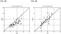
- FIG. 4A is a view illustrating relationships between the calculated value esCCO (the ordinate) of the cardiac output before correction, and a measured value ICO (the abscissa) of the cardiac output
- FIG. 4B is a view illustrating relationships between the calculated value esCCO (the ordinate) of the cardiac output after correction, and the measured value ICO (the abscissa) of the cardiac output.
- the calculated value esCCO of the cardiac output before correction which is illustrated in FIG. 4A corresponds to the cardiac output that is calculated in step S12 of FIG. 3 .
- the calculated value of the cardiac output after correction which is illustrated in FIG. 4B corresponds to the cardiac output that is corrected in step S15 of FIG. 3 .
- the processes (particularly, the processes illustrated in steps S12 to S15) illustrated in FIG. 3 may be repeatedly performed every predetermined time interval (for example, every one second).
- the controller 2 acquires an (n+1)-th esCCO n+1 or corrected esCCO n+1 after an elapse of a predetermined time period from acquisition of an n-th esCCO n or corrected esCCO n .
- the SVR is used as an example of the vascular distensibility parameter
- the vascular distensibility parameter is not limited to the SVR.
- the arterial elastic modulus, the dynamic arterial elastic modulus, or the pulse-amplitude index may be used as an example of the vascular distensibility parameter.
- the calculated value of the cardiac output is corrected in consideration of the arterial elastic modulus, the dynamic arterial elastic modulus, or the pulsation rate, and therefore it is possible to provide the processing apparatus 1 in which the calculation accuracy of the cardiac output of the subject can be further improved.
- the physiological information processing program may be pre-installed in the storage device 3 or the ROM.
- the physiological information processing program may be stored on a computer readable storage medium such as a magnetic disk (such as an HDD or a floppy disk), an optical disk (such as a CD-ROM, a DVD-ROM, or a Blu-ray (registered trademark) disk), a magneto-optical disk (such as an MO), or a flash memory (such as an SD card, a USB memory, or an SSD).
- a computer readable storage medium such as a magnetic disk (such as an HDD or a floppy disk), an optical disk (such as a CD-ROM, a DVD-ROM, or a Blu-ray (registered trademark) disk), a magneto-optical disk (such as an MO), or a flash memory (such as an SD card, a USB memory, or an SSD).
- the physiological information processing program which is stored in the storage medium may be installed in the storage device 3.
- the physiological information processing program may be downloaded from a computer on a communication network, through the network interface 4.
- the downloaded program may be installed in the storage device 3.
Landscapes
- Health & Medical Sciences (AREA)
- Life Sciences & Earth Sciences (AREA)
- Cardiology (AREA)
- Engineering & Computer Science (AREA)
- Heart & Thoracic Surgery (AREA)
- Surgery (AREA)
- Biophysics (AREA)
- Pathology (AREA)
- Veterinary Medicine (AREA)
- Biomedical Technology (AREA)
- Public Health (AREA)
- Medical Informatics (AREA)
- Molecular Biology (AREA)
- Physics & Mathematics (AREA)
- Animal Behavior & Ethology (AREA)
- General Health & Medical Sciences (AREA)
- Physiology (AREA)
- Vascular Medicine (AREA)
- Hematology (AREA)
- Signal Processing (AREA)
- Computer Networks & Wireless Communication (AREA)
- Measuring Pulse, Heart Rate, Blood Pressure Or Blood Flow (AREA)
- Measurement And Recording Of Electrical Phenomena And Electrical Characteristics Of The Living Body (AREA)
Abstract
Description
- The invention relates to a physiological information processing apparatus and a physiological information processing method. The invention further relates to a program for causing a computer to execute the physiological information processing method, and a computer readable storage medium on which the program is stored.
- Japanese Patent No.
5779299 5779299 - Recently, it has been reported that the cardiac output of a patient varies in accordance with a parameter relating to the vascular distensibility such as the systemic vascular resistance (hereinafter, such a parameter is referred to as "vascular distensibility parameter"). Therefore, it is desired to calculate the cardiac output of a patient in consideration of the vascular distensibility parameter of the patient. In the case where the cardiac output of a patient is calculated without considering the vascular distensibility parameter of the patient, there is a possibility that a large discrepancy arises between a measured value of the cardiac output which is invasively measured by a cardiac output sensor, and a calculation value of the cardiac output which is calculated by using the heart rate and pulse wave transit time (hereinafter, referred to as PWTT) of the patient. When attention is focused on the phenomenon that the cardiac output varies in accordance with the vascular distensibility parameter (i.e., dependence on the vascular distensibility parameter), consequently, there is room for further improvement of the calculation accuracy of the cardiac output.
- It is an object of the invention to provide a physiological information processing method and apparatus which can further improve the calculation accuracy of the cardiac output of a patient. It is another object of the invention to provide a program for causing a computer to execute the physiological information processing method, and a computer readable storage medium on which the program is stored.
- A physiological information processing method of one mode of the invention is to be executed by a computer, and includes:
- acquiring electrocardiogram data of a subject;
- acquiring pulse wave data of the subject;
- measuring a heart rate based on the electrocardiogram data;
- measuring a pulse wave transit time based on the electrocardiogram data and the pulse wave data;
- calculating a cardiac output based on the pulse wave transit time and heart rate which have been measured;
- calculating a vascular distensibility parameter relating to a vascular distensibility; and
- correcting the calculated cardiac output based on the vascular distensibility parameter.
- Moreover, a program for causing a computer to execute the physiological information processing method, and a computer readable storage medium on which the program is stored are provided.
- A physiological information processing apparatus of one mode of the invention includes:
- one or more processor; and
- one or more memory which stores computer readable instructions.
- When the computer readable instructions are executed by the processor, the physiological information processing apparatus
acquires electrocardiogram data of a subject,
acquires pulse wave data of the subject,
measures a heart rate based on the electrocardiogram data,
measures a pulse wave transit time based on the electrocardiogram data and the pulse wave data,
calculates a cardiac output based on the pulse wave transit time and heart rate which have been measured,
calculates a vascular distensibility parameter relating to a vascular distensibility, and
corrects the calculated cardiac output based on the vascular distensibility parameter. - According to the invention, it is possible to provide a physiological information processing method and apparatus which can further improve the calculation accuracy of the cardiac output of a patient. Moreover, it is possible to provide a program for causing a computer to execute the physiological information processing method, and a computer readable storage medium on which the program is stored.
-
-
FIG. 1 illustrates an example of a hardware configuration of a physiological information processing apparatus of an embodiment of the presently disclosed subject matter. -
FIG. 2 is a flowchart for explaining an example of a physiological information processing method of the embodiment of the presently disclosed subject matter. -
FIG. 3 is a flowchart for explaining an example of a physiological information processing method of a modification of the embodiment of the presently disclosed subject matter. -
FIG. 4A illustrates relationships between a calculated value of the cardiac output before correction and a measured value of the cardiac output, andFIG. 4B illustrates relationships between a calculated value of the cardiac output after correction and the measured value of the cardiac output. - Hereinafter, an embodiment will be described with reference to the drawings. Initially, the hardware configuration of a physiological information processing apparatus 1 of an embodiment of the presently disclosed subject matter (hereinafter, referred to simply as the embodiment) will be described.
-
FIG. 1 illustrates an example of the hardware configuration of the physiological information processing apparatus 1 of the embodiment. As illustrated inFIG. 1 , the physiological information processing apparatus 1 (hereinafter, referred to simply as the processing apparatus 1) includes acontroller 2, astorage device 3, a network interface 4, a displayingsection 5, aninput operating section 6, and asensor interface 7. These components are communicably connected to one another via abus 8. - The processing apparatus 1 may be an apparatus (a patient monitor or the like) dedicated to display of a trend graph of vital signs of a subject P, or, for example, a personal computer, a workstation, a smart phone, a tablet, or a wearable device (such as a smart watch or an AR glass) which is to be attached to the body (such as the arm or the head) of a medical person U.
- The
controller 2 includes a memory and a processor. The memory is configured so as to store computer readable instructions (programs), and may be configured by, for example, a ROM (Read Only Memory) which stores various programs and the like, and a RAM (Random Access Memory) having a plurality of work areas in which various programs to be executed by the processor, and the like are stored. Alternatively, the memory may be configured by a flash memory or the like. For example, the processor is a CPU (Central Processing Unit), an MPU (Micro Processing Unit), and/or a GPU (Graphics Processing Unit). The CPU may be configured by a plurality of CPU cores. The GPU may be configured by a plurality of GPU cores. The processor may be configured so as to develop a designated one of the various programs installed in thestorage device 3 or the ROM, in the RAM, and execute various processes in cooperation with the RAM. - The processor may develop a physiological information processing program which will be described later, in the RAM, and execute the program in cooperation with the RAM, thereby enabling the
controller 2 to control various operations of the processing apparatus 1. The physiological information processing program will be described in detail later. - For example, the
storage device 3 is a storage device such as an HDD (Hard Disk Drive), an SSD (Solid State Drive), or a flash memory, and configured so as to store programs and various data. The physiological information processing program may be incorporated in thestorage device 3. Thestorage device 3 may store physiological information data such as electrocardiogram data, blood pressure data, and pulse wave data of the subject P. For example, electrocardiogram data which are acquired by anelectrocardiogram sensor 20 may be stored in thestorage device 3 through thesensor interface 7. - The network interface 4 is configured so as to connect the processing apparatus 1 to a communication network. Specifically, the network interface 4 may include various wired connection terminals for communicating with an external apparatus such as a server through the communication network. The network interface 4 may further include various processing circuits, antenna, and the like for wirelessly communicating with an access point. For example, the standard of wireless communication between the access point and the processing apparatus 1 is the Wi-Fi (registered trademark), the Bluetooth (registered trademark), the ZigBee (registered trademark), the LPWA, or a fifth generation mobile communication system (5G). The communication network is a LAN (Local Area Network), a WAN (Wide Area Network), the Internet, or the like. For example, the physiological information processing program and physiological information data may be acquired from the server placed in the communication network through the network interface 4.
- The displaying
section 5 may be a display device such as a liquid crystal display or an organic EL display, or that such as a transmission or non-transmission head mounted display which is to be attached to the head of the operator. Alternatively, the displayingsection 5 may be a projector device which projects an image onto a screen. - The
input operating section 6 is configured so as to receive an input operation performed by the medical person U who operates the processing apparatus 1, and produce an instruction signal corresponding to the input operation. For example, theinput operating section 6 is configured by a touch panel which is placed overlappingly on the displayingsection 5, operation buttons which are attached to the housing, or a mouse and/or a keyboard. The instruction signal which is produced by theinput operating section 6 is transmitted to thecontroller 2 via thebus 8, and then thecontroller 2 executes a predetermined operation according to the instruction signal. - The
sensor interface 7 is an interface which enables vital sensors such as theelectrocardiogram sensor 20, ablood pressure sensor 21, and apulse wave sensor 22 to be communicably connected to the processing apparatus 1. Thesensor interface 7 may include input terminals to which the physiological data output from these vital sensors are input. The input terminals may be physically connected to connectors of the vital sensors. Thesensor interface 7 may further include various processing circuits, antenna, and the like for wirelessly communicating with the vital sensors. - The
electrocardiogram sensor 20 is configured so as to acquire electrocardiogram data indicating the electrocardiogram waveform of the subject P. Thepulse wave sensor 22 is configured so as to acquire pulse wave data indicating the pulse wave of the subject P. Theblood pressure sensor 21 is configured so as to acquire blood pressure data indicating a temporal change of the blood pressure (particularly, the arterial blood pressure and/or the venous blood pressure) of the subject P. Theblood pressure sensor 21 may be configured by a plurality of blood pressure sensors. Theblood pressure sensor 21 may invasively acquire the blood pressure data of the subject P, or non-invasively acquire the blood pressure data of the subject P. Acardiac output sensor 23 is configured so as to acquire cardiac output data indicating a temporal change of the cardiac output of the subject P. - Next, a physiological information processing method of the embodiment will be described with reference to
FIG. 2. FIG. 2 is a flowchart illustrating an example of the physiological information processing method of the embodiment. As illustrated inFIG. 2 , thecontroller 2 firstly acquires the electrocardiogram data from theelectrocardiogram sensor 20, and the pulse wave data from thepulse wave sensor 22. Next, thecontroller 2 measures the heart rate of the subject P based on the acquired electrocardiogram data (step S1). Specifically, thecontroller 2 specifies a plurality of RR intervals indicating the time intervals between adjacent R waves during a predetermined time period, from the electrocardiogram data. Then, thecontroller 2 calculates the mean RR interval indicating the mean value of the plurality of RR intervals during the predetermined time period, and thereafter measures the heart rate (bpm) of the subject P from the mean RR interval based on the relational expression of "heart rate = 60/mean RR interval." Thecontroller 2 may calculate the heart rate every predetermined time interval (for example, every one second). - Next, the
controller 2 measures in step S2 the pulse wave transit time (hereinafter, referred to as PWTT) based on the electrocardiogram data and the pulse wave data. The PWTT means a time interval from the peak point of a predetermined R wave of an electrocardiogram to the rising point of a predetermined pulse waveform which appears next to the predetermined R wave. Therefore, thecontroller 2 specifies the time of the peak point of the predetermined R wave from the electrocardiogram data, and further specifies that of the rising point of the predetermined pulse waveform which appears next to the predetermined R wave, from the pulse wave data. Next, thecontroller 2 calculates the time interval between the time of the rising point of the predetermined pulse waveform and that of the peak point of the predetermined R wave, thereby measuring the PWTT. Thecontroller 2 may calculate the PWTT every predetermined time interval (for example, every one second). - Next, the
controller 2 calculates the cardiac output of the subject P based on the PWTT and heart rate which have been measured (step S3). Specifically, thecontroller 2 calculates the cardiac output from the PWTT and the heart rate in accordance with following relational expression (1). In the expression, esCCO (estimated Continuous Cardiac Output) indicates a calculated cardiac output, HR indicates the heart rate, and K0, α, and β are specific coefficients which are set for each subject. Specific examples of methods for deriving the coefficients K0, α, and β are described in, for example, Japanese - Patent No.
4,742,644 controller 2 may calculate the cardiac output every predetermined time interval (for example, every one second).
- Next, the
controller 2 calculates in step S4 the systemic vascular resistance (hereinafter, referred to as SVR) of the subject P. The SVR is an example of the vascular distensibility parameter relating to the vascular distensibility of the subject P. Specifically, thecontroller 2 acquires blood pressure data indicating a temporal change of the arterial blood pressure from theblood pressure sensor 21, and then calculates the mean blood pressure (MAP) of the subject P from the acquired blood pressure data. Moreover, thecontroller 2 acquires blood pressure data indicating a temporal change of the central venous pressure (CVP) from theblood pressure sensor 21. Furthermore, thecontroller 2 acquires cardiac output data indicating a temporal change of the cardiac output from thecardiac output sensor 23, and then calculates the cardiac output CO. Thereafter, thecontroller 2 calculates the SVR from the mean blood pressure (MAP), the central venous pressure (CVP), and the cardiac output (CO) in accordance with following relational expression (2):
- Further, the
controller 2 may calculate the SVR every predetermined time interval (for example, every one second). - Next, the
controller 2 determines in step S5 whether the newly calculated SVR satisfies a predetermined condition associated with the previously calculated SVR or not. The previously calculated SVR may be the SVRn-1 (n is an integer of 2 or more) which is calculated just before the newly calculated SVRn, the initially calculated SVR (i.e., SVR1), or an SVRm (m is an integer that is smaller than n) which is calculated before a predetermined time period. - Examples of "predetermined condition associated with the previously calculated SVR" are the following three conditions:
- 1) condition associated with a variation ΔSVR between the newly calculated SVR and the previously calculated SVR;
- 2) condition associated with a ratio of the variation ΔSVR to the newly calculated SVR or the previously calculated SVR; and
- 3) condition associated with a predetermined range which is set based on the previously calculated SVR.
- The above conditions 1) to 3) will be described in detail below. For the sake of convenience of the description, "previously calculated SVR" is assumed to be the SVRn-1 which is calculated just before.
- In the case of condition 1), the
controller 2 determines whether the variation ΔSVR = |SVRn - SVRn-1| between the newly calculated SVRn and the just before calculated SVRn-1 is equal to or smaller than a predetermined value ΔSVRth or not. Here, the predetermined value ΔSVRth can be appropriately set on the side of a medical facility. If it is determined that the variation ΔSVR is equal to or smaller than the predetermined value ΔSVRth (in step S5, YES), thecontroller 2 ends the process. By contrast, if it is determined that the variation ΔSVR is larger than the predetermined value ΔSVRth (in step S5, NO), thecontroller 2 executes the process of step S6. - In the case of condition 2), the
controller 2 determines whether the ratio R of the variation ΔSVR = |SVRn - SVRn-1| to the newly calculated SVRn (or the just before calculated SVRn-1) is equal to or smaller than a predetermined value Rth or not. Here, R = ΔSVR/SVRn × 100% or R = ΔSVR/SVRn-1 × 100%. The predetermined value Rth can be appropriately set on the side of the medical facility. If it is determined that the ratio R is equal to or smaller than the predetermined value Rth (in step S5, YES), thecontroller 2 ends the process. By contrast, if it is determined that the ratio R is larger than the predetermined value Rth (in step S5, NO), thecontroller 2 executes the process of step S6. - In the case of condition 3), if it is determined that the newly calculated SVRn is included within a predetermined range S which is set based on the previously calculated SVRn-1 (in step S5, YES), the
controller 2 ends the process. By contrast, if it is determined that the newly calculated SVRn is not included within the predetermined range S which is set based on the previously calculated SVRn-1 (in step S5, NO), thecontroller 2 executes the process of step S6. Here, the predetermined range S may be set as SVRn-1 ± γ (γ is a predetermined value). If it is determined that the SVRn is SVRn-1 - γ ≤ SVRn ≤ SVRn-1 + γ (in step S5, YES), thecontroller 2 ends the process. By contrast, if it is determined that the SVRn is not SVRn-1 - γ ≤ SVRn ≤ SVRn-1 + γ (in step S5, NO), thecontroller 2 executes the process of step S6. - As described above, in the case where the newly calculated SVRn largely varies from the just before calculated SVRn-1, the determination result of step S5 is NO, and, in the case where the newly calculated SVRn does not largely vary from the just before calculated SVRn-1, the determination result of step S5 is YES. In this way, in the case where the predetermined condition is satisfied in step S5 (in other words, in the case where the SVRn does not largely vary from the SVRn-1), the processes of steps S6 and S7 are not executed, and therefore the computing load of the controller 2 (processor) can be reduced.
- Next, the
controller 2 corrects in step S6 the coefficient K0 which is used in relational expression (1), based on the newly calculated SVRn. For example, thecontroller 2 can calculate the corrected coefficient K0 from the SVRn, based on following relational expression (3):
- Here, the slope c and the intercept d are values which are determined by linearly approximating the correlation between ΔKi = Ki-K0 (i is an integer of 1 or more) and the SVRi, respectively. Namely, the correlation between ΔKi and the SVRi can be expressed as a linear function (ΔKi = c × SVRi + d) based on a plurality of ΔKi and a plurality of SVRi each of which is associated with corresponding one of the plurality of ΔKi. In this way, the slope c and the intercept d can be determined. The values of the slope c and the intercept d may be appropriately set on the side of the medical facility.
- Next, the
controller 2 again calculates in step S7 the cardiac output based on the corrected coefficient K0, thereby correcting the cardiac output (esCCO) which is calculated in step S3. Specifically, thecontroller 2 again calculates the cardiac output based on following relational expression (4):
- According to the embodiment, as described above, the coefficient K0 is corrected based on the newly calculated SVRn, and then the cardiac output is again calculated based on the corrected coefficient K0. Since the calculated cardiac output is corrected in consideration of the SVR which is an example of the vascular distensibility parameter as described above, it is possible to provide the processing apparatus 1 in which the calculation accuracy of the cardiac output of the subject can be further improved.
- The processes (particularly, the processes illustrated in steps S3 to S7) illustrated in
FIG. 2 may be repeatedly performed every predetermined time interval (for example, every one second). For example, thecontroller 2 acquires an (n+1)-th esCCOn+1 or corrected esCCOn+1 after an elapse of a predetermined time period from acquisition of an n-th esCCOn or corrected esCCOn. The sequence of the processes illustrated inFIG. 2 is not particularly limited. For example, the process of step S1 may be performed after that of step S2. Moreover, the process of step S4 may be performed before that of step S1. - Next, a physiological information processing method of a modification of the embodiment (hereinafter, referred to merely as modification) will be described with reference to
FIG. 3. FIG. 3 is a flowchart illustrating an example of the physiological information processing method of the modification. The physiological information processing method of the modification is different from that of the embodiment in the method for correcting the calculated value of the cardiac output. Therefore, the processes of steps S10 to S14 illustrated inFIG. 3 are identical with those of steps S1 to S5 illustrated inFIG. 2 , and hence only the process of step S15 will be described below. - As illustrated in
FIG. 3 , in step S15, thecontroller 2 adds a value which is calculated based on the newly calculated SVRn, to the cardiac output that is calculated in step S12, thereby correcting the cardiac output that is calculated in step S12. Specifically, thecontroller 2 corrects the cardiac output based on following relational expression (5).
- Here, the slope e and the intercept f are values which are determined by linearly approximating the correlation between ΔesCCOi = esCCOi-esCCO0 (i is an integer of 1 or more) and the SVRi, respectively, and esCCO0 is a predetermined cardiac output which is determined in the case of PWTT = PWTT0 and HR = HR0. For example, PWTT0 is the value of the PWTT in the stable condition of the subject, and HR0 is the value of HR in the stable condition of the subject.
- Namely, the correlation between the ΔesCCOi and the SVRi can be expressed as a linear function (ΔesCCOi = e × SVRi + f) based on a plurality of ΔesCCOi and a plurality of SVRi each of which is associated with corresponding one of the plurality of ΔesCCOi. In this way, the slope e and the intercept f can be determined. The values of the slope e and the intercept f may be appropriately set on the side of the medical facility.
- According to the modification, as described above, the calculated value of the cardiac output is corrected by adding the value of ΔesCCO = e × SVRn + f which is calculated based on the newly calculated SVRn, to the cardiac output which is calculated in step S12. Since the calculated value of the cardiac output is corrected in consideration of the SVR which is an example of the vascular distensibility parameter as described above, it is possible to provide the processing apparatus 1 in which the calculation accuracy of the cardiac output of the subject can be further improved.
- In this respect, the degree by which the calculation accuracy of the cardiac output is improved will be described with reference to
FIGS. 4A and 4B. FIG. 4A is a view illustrating relationships between the calculated value esCCO (the ordinate) of the cardiac output before correction, and a measured value ICO (the abscissa) of the cardiac output, andFIG. 4B is a view illustrating relationships between the calculated value esCCO (the ordinate) of the cardiac output after correction, and the measured value ICO (the abscissa) of the cardiac output. Here, the calculated value esCCO of the cardiac output before correction which is illustrated inFIG. 4A corresponds to the cardiac output that is calculated in step S12 ofFIG. 3 . By contrast, the calculated value of the cardiac output after correction which is illustrated inFIG. 4B corresponds to the cardiac output that is corrected in step S15 ofFIG. 3 . In the case where the accuracy of a calculated value of the cardiac output is high, it is contemplated that a plurality of plots each of which is configured by calculated and measured values of the cardiac output are located on or in the vicinity of a linear line expressed by esCCO = ICO. Form this point of view, when the plots illustrated inFIG. 4A are compared with those illustrated inFIG. 4B , it is known that the plots illustrated inFIG. 4B are nearer to the linear line showing esCCO = ICO than those illustrated inFIG. 4A . Therefore, it is understood that the accuracy of a calculated value of the cardiac output is improved by correcting the calculated value of the cardiac output based on the SVR. - The processes (particularly, the processes illustrated in steps S12 to S15) illustrated in
FIG. 3 may be repeatedly performed every predetermined time interval (for example, every one second). For example, thecontroller 2 acquires an (n+1)-th esCCOn+1 or corrected esCCOn+1 after an elapse of a predetermined time period from acquisition of an n-th esCCOn or corrected esCCOn. - Although, in the descriptions of the embodiment and the modification, the SVR is used as an example of the vascular distensibility parameter, the vascular distensibility parameter is not limited to the SVR. In place of the SVR, for example, the arterial elastic modulus, the dynamic arterial elastic modulus, or the pulse-amplitude index may be used as an example of the vascular distensibility parameter. Also in this case, samely or similarly, the calculated value of the cardiac output is corrected in consideration of the arterial elastic modulus, the dynamic arterial elastic modulus, or the pulsation rate, and therefore it is possible to provide the processing apparatus 1 in which the calculation accuracy of the cardiac output of the subject can be further improved.
- In order to realize the processing apparatus 1 of the embodiment by using software, the physiological information processing program may be pre-installed in the
storage device 3 or the ROM. Alternatively, the physiological information processing program may be stored on a computer readable storage medium such as a magnetic disk (such as an HDD or a floppy disk), an optical disk (such as a CD-ROM, a DVD-ROM, or a Blu-ray (registered trademark) disk), a magneto-optical disk (such as an MO), or a flash memory (such as an SD card, a USB memory, or an SSD). In the alternative, when the physiological information processing program which is stored in the storage medium may be installed in thestorage device 3. Then, the program which is installed in thestorage device 3 is loaded into the RAM, and thereafter the processor executes the program which is loaded into the RAM. In this way, the physiological information processing method of the embodiment is executed by the processing apparatus 1. - The physiological information processing program may be downloaded from a computer on a communication network, through the network interface 4. The downloaded program may be installed in the
storage device 3. - Although the embodiment of the presently disclosed subject matter has been described, the technical scope of the presently disclosed subject matter should not be limitedly interpreted by the description of the embodiment. It should be understood by those skilled in the art that the embodiment is a mere example, and may be variously changed within the scope of the presently disclosed subject matter as defined in the claims. The technical scope of the presently disclosed subject matter should be determined based on the scope of the presently disclosed subject matter as defined in the claims, and the scope of equivalence thereof.
Claims (14)
- A physiological information processing method that is executed by a computer, the method comprising:acquiring electrocardiogram data of a subject;acquiring pulse wave data of the subject;measuring a heart rate based on the electrocardiogram data;measuring a pulse wave transit time based on the electrocardiogram data and the pulse wave data;calculating a cardiac output based on the measured pulse wave transit time and the measured heart rate;calculating a vascular distensibility parameter relating to a vascular distensibility; andcorrecting the calculated cardiac output based on the vascular distensibility parameter.
- The physiological information processing method according to claim 1,
wherein when the calculated vascular distensibility parameter does not satisfy a predetermined condition associated with a previously calculated vascular distensibility parameter, the correcting of the calculated cardiac output is performed. - The physiological information processing method according to claim 2,
wherein the predetermined condition is associated with any one ofa variation between the calculated vascular distensibility parameter and the previously calculated vascular distensibility parameter,a ratio of the variation between the calculated vascular distensibility parameter and the previously calculated vascular distensibility parameter, to the calculated vascular distensibility parameter or the previously calculated vascular distensibility parameter, anda predetermined range which is set based on the previously calculated vascular distensibility parameter. - The physiological information processing method according to claim 2 or 3,
wherein the previously calculated vascular distensibility parameter is a just before calculated vascular distensibility parameter, an initially calculated vascular distensibility parameter, or a vascular distensibility parameter which is calculated before a predetermined time period. - The physiological information processing method according to any one of claims 1 to 4,
wherein the vascular distensibility parameter is a systemic vascular resistance, an arterial elastic modulus, a dynamic arterial elastic modulus, or a pulse-amplitude index. - The physiological information processing method according to any one of claims 1 to 5,
wherein in the calculating of a cardiac output, the cardiac output is calculated by a following expression: where esCCO is the cardiac output,PWTT is the pulse wave transit time,HR is the heart rate, andK0, α, and β are arbitrary values, andwherein the correcting of the calculated cardiac output includes:correcting the coefficient K0 based on the vascular distensibility parameter; and again calculating the cardiac output based on the corrected coefficient K0,, oradding a value which is calculated based on the vascular distensibility parameter, to the calculated cardiac output, thereby correcting the calculated cardiac output.
 - A program for causing a computer to execute the physiological information processing method according to any one of claims 1 to 6.
- A computer readable storage medium on which the program according to claim 7 is stored.
- A physiological information processing apparatus comprising:one or more processor; andone or more memory which stores computer readable instructions,wherein when the computer readable instructions are executed by the processor, the physiological information processing apparatus configured toacquire electrocardiogram data of a subject,acquire pulse wave data of the subject,measure a heart rate based on the electrocardiogram data,measure a pulse wave transit time based on the electrocardiogram data and the pulse wave data,calculate a cardiac output based on the measured pulse wave transit time and the measured heart rate,calculate a vascular distensibility parameter relating to a vascular distensibility, andcorrect the calculated cardiac output based on the vascular distensibility parameter.
- The physiological information processing apparatus according to claim 9,
wherein in a case where the calculated vascular distensibility parameter does not satisfy a predetermined condition associated with a previously calculated vascular distensibility parameter, the physiological information processing apparatus corrects the calculated cardiac output based on the vascular distensibility parameter. - The physiological information processing apparatus according to claim 10,
wherein the predetermined condition is associated with any one ofa variation between the calculated vascular distensibility parameter and the previously calculated vascular distensibility parameter,a ratio of the variation between the calculated vascular distensibility parameter and the previously calculated vascular distensibility parameter, to the calculated vascular distensibility parameter or the previously calculated vascular distensibility parameter, anda predetermined range which is set based on the previously calculated vascular distensibility parameter. - The physiological information processing apparatus according to any one of claims 9 to 11,
wherein the previously calculated vascular distensibility parameter is a just before calculated vascular distensibility parameter, an initially calculated vascular distensibility parameter, or a vascular distensibility parameter which is calculated before a predetermined time period. - The physiological information processing apparatus according to any one of claims 9 to 12,
wherein the vascular distensibility parameter is a systemic vascular resistance, an arterial elastic modulus, a dynamic arterial elastic modulus, or pulse-amplitude index. - The physiological information processing apparatus according to any one of claims 9 to 13,
wherein the physiological information processing apparatus is configured to calculate the cardiac output by a following expression: where esCCO is the cardiac output,PWTT is the pulse wave transit time,HR is the heart rate, andK0, α, and β are arbitrary values, andwherein the physiological information processing apparatus is configured tocorrect the coefficient K0 based on the vascular distensibility parameter, and then again calculate the cardiac output based on the corrected coefficient K0, thereby correcting the calculated cardiac output, oradd a value which is calculated based on the vascular distensibility parameter, to the calculated cardiac output, thereby correcting the calculated cardiac output.
Applications Claiming Priority (1)
| Application Number | Priority Date | Filing Date | Title |
|---|---|---|---|
| JP2018062700A JP7096035B2 (en) | 2018-03-28 | 2018-03-28 | Biometric information processing equipment, biometric information processing methods, programs and storage media |
Publications (2)
| Publication Number | Publication Date |
|---|---|
| EP3545828A1 true EP3545828A1 (en) | 2019-10-02 |
| EP3545828B1 EP3545828B1 (en) | 2025-08-27 |
Family
ID=65991612
Family Applications (1)
| Application Number | Title | Priority Date | Filing Date |
|---|---|---|---|
| EP19165191.8A Active EP3545828B1 (en) | 2018-03-28 | 2019-03-26 | Physiological information processing apparatus and physiological information processing method |
Country Status (3)
| Country | Link |
|---|---|
| US (1) | US11426082B2 (en) |
| EP (1) | EP3545828B1 (en) |
| JP (1) | JP7096035B2 (en) |
Families Citing this family (5)
| Publication number | Priority date | Publication date | Assignee | Title |
|---|---|---|---|---|
| JP7461805B2 (en) * | 2020-06-15 | 2024-04-04 | 日本光電工業株式会社 | Circulatory dynamics analysis device and circulatory dynamics analysis program |
| EP3964124A1 (en) * | 2020-09-02 | 2022-03-09 | Koninklijke Philips N.V. | Method and apparatus for estimating the reliability of cardiac output measurements |
| EP4554462A1 (en) * | 2022-07-13 | 2025-05-21 | BaroPace, Inc. | Systems and methods for determining systemic vascular resistance using bioimpedance |
| IL317117A (en) * | 2022-07-13 | 2025-01-01 | Baropace Inc | Systems and methods for determining systemic vascular resistance using photoplethysmography |
| CN120093259A (en) * | 2023-12-04 | 2025-06-06 | 深圳市理邦精密仪器股份有限公司 | Physiological parameter display method, device, equipment and storage medium |
Citations (4)
| Publication number | Priority date | Publication date | Assignee | Title |
|---|---|---|---|---|
| US20050222514A1 (en) * | 2004-03-31 | 2005-10-06 | Nihon Kohden Corporation | Method and apparatus for measuring blood volume, and vital sign monitor using the same |
| EP2241251A1 (en) * | 2009-04-17 | 2010-10-20 | Nihon Kohden Corporation | Method and apparatus for measuring blood volume |
| JP4742644B2 (en) | 2004-03-31 | 2011-08-10 | 日本光電工業株式会社 | Blood volume measuring method, measuring apparatus and biological signal monitoring apparatus |
| JP5779299B2 (en) | 2012-05-15 | 2015-09-16 | コーニンクレッカ フィリップス エヌ ヴェ | Monitoring cardiac output |
Family Cites Families (2)
| Publication number | Priority date | Publication date | Assignee | Title |
|---|---|---|---|---|
| JP5410210B2 (en) * | 2009-09-08 | 2014-02-05 | 日本光電工業株式会社 | Artifact removal method, blood volume measuring device and artifact removal program in respiratory stroke fluctuation analysis device for stroke volume |
| JP5985355B2 (en) * | 2012-10-30 | 2016-09-06 | 日本光電工業株式会社 | Blood volume measuring method and measuring apparatus |
-
2018
- 2018-03-28 JP JP2018062700A patent/JP7096035B2/en active Active
-
2019
- 2019-03-18 US US16/356,593 patent/US11426082B2/en active Active
- 2019-03-26 EP EP19165191.8A patent/EP3545828B1/en active Active
Patent Citations (4)
| Publication number | Priority date | Publication date | Assignee | Title |
|---|---|---|---|---|
| US20050222514A1 (en) * | 2004-03-31 | 2005-10-06 | Nihon Kohden Corporation | Method and apparatus for measuring blood volume, and vital sign monitor using the same |
| JP4742644B2 (en) | 2004-03-31 | 2011-08-10 | 日本光電工業株式会社 | Blood volume measuring method, measuring apparatus and biological signal monitoring apparatus |
| EP2241251A1 (en) * | 2009-04-17 | 2010-10-20 | Nihon Kohden Corporation | Method and apparatus for measuring blood volume |
| JP5779299B2 (en) | 2012-05-15 | 2015-09-16 | コーニンクレッカ フィリップス エヌ ヴェ | Monitoring cardiac output |
Non-Patent Citations (2)
| Title |
|---|
| G R�DIG ET AL: "Continuous cardiac output measurement: pulse contour analysis vs thermodilution technique in cardiac surgical patients", BRITISH JOURNAL OF ANAESTHESIA, vol. 82, 1 April 1999 (1999-04-01), pages 525 - 530, XP055595222, DOI: 10.1093/bja/82.4.525 * |
| J A ALHASHEMI, M CECCONI, C K HOFER: "Cardiac output monitoring: an integrative perspective", CRITICAL CARE, 22 March 2011 (2011-03-22), XP055311012, Retrieved from the Internet <URL:https://ccforum.biomedcentral.com/track/pdf/10.1186/cc9996> [retrieved on 20190610], DOI: 10.1186/cc9996 * |
Also Published As
| Publication number | Publication date |
|---|---|
| JP7096035B2 (en) | 2022-07-05 |
| US20190298180A1 (en) | 2019-10-03 |
| EP3545828B1 (en) | 2025-08-27 |
| US11426082B2 (en) | 2022-08-30 |
| JP2019170709A (en) | 2019-10-10 |
Similar Documents
| Publication | Publication Date | Title |
|---|---|---|
| US11426082B2 (en) | Physiological information processing apparatus and physiological information processing method | |
| US10905381B2 (en) | Blood pressure correction information generating device, blood pressure measurement device and blood pressure correction information generating method | |
| US20210169348A1 (en) | Physiological information processing apparatus, physiological information processing method, program and storage medium | |
| EP3251590A1 (en) | Method and system for monitoring blood pressure in real-time, and non-transitory computer-readable recording medium | |
| US11284829B2 (en) | Apparatus and method for processing physiological information | |
| US10750961B2 (en) | Diagnosis assistance apparatus, diagnosis assistance method, diagnosis assistance program | |
| US20220409129A1 (en) | Physiological information processing method, physiological information processing device, and physiological information processing system | |
| CN108471966B (en) | Diagnosis aid device, diagnosis aid method, and diagnosis aid program | |
| KR20100126128A (en) | Low pressure blood pressure measuring device and method | |
| US10856762B2 (en) | Atrial fibrillation detector, atrial fibrillation detecting method, and computer readable medium | |
| US20210059613A1 (en) | Risk management device, risk management method, and non-temporary recording medium in which risk management program is stored | |
| US20200196909A1 (en) | Systems, methods, and apparatuses for peripheral arterial disease detection and mitigation thereof | |
| US20220192519A1 (en) | Physiological information processing device, physiological information processing method, program and storage medium | |
| EP4285815A1 (en) | Arterial pressure estimation device, arterial pressure estimation system, and arterial pressure estimation method | |
| US20250275726A1 (en) | Method for training a machine learning model, monitoring device, and monitoring method | |
| US20210259617A1 (en) | Physiological information processing apparatus, physiological information processing methdo and storage medium | |
| US11172820B2 (en) | Physiological information processing apparatus, physiological information processing method, and storage medium | |
| KR102296214B1 (en) | Apparatus, method and computer for managing ecg data | |
| US20190365243A1 (en) | Blood-pressure-related information display apparatus and method | |
| US11974839B2 (en) | Circulatory dynamic measuring apparatus and circulatory dynamic measuring method | |
| JP2018110725A (en) | Waveform display apparatus, waveform display method, program, and recording medium | |
| KR20080017525A (en) | Recording medium recording blood pressure control device and program. | |
| JP2016067481A (en) | Bio-information detection apparatus | |
| JP2016067480A (en) | Biological information detection device | |
| US20210121079A1 (en) | Apparatus for measuring hemodynamic parameters |
Legal Events
| Date | Code | Title | Description |
|---|---|---|---|
| PUAI | Public reference made under article 153(3) epc to a published international application that has entered the european phase |
Free format text: ORIGINAL CODE: 0009012 |
|
| STAA | Information on the status of an ep patent application or granted ep patent |
Free format text: STATUS: THE APPLICATION HAS BEEN PUBLISHED |
|
| AK | Designated contracting states |
Kind code of ref document: A1 Designated state(s): AL AT BE BG CH CY CZ DE DK EE ES FI FR GB GR HR HU IE IS IT LI LT LU LV MC MK MT NL NO PL PT RO RS SE SI SK SM TR |
|
| AX | Request for extension of the european patent |
Extension state: BA ME |
|
| STAA | Information on the status of an ep patent application or granted ep patent |
Free format text: STATUS: REQUEST FOR EXAMINATION WAS MADE |
|
| 17P | Request for examination filed |
Effective date: 20200326 |
|
| RBV | Designated contracting states (corrected) |
Designated state(s): AL AT BE BG CH CY CZ DE DK EE ES FI FR GB GR HR HU IE IS IT LI LT LU LV MC MK MT NL NO PL PT RO RS SE SI SK SM TR |
|
| STAA | Information on the status of an ep patent application or granted ep patent |
Free format text: STATUS: EXAMINATION IS IN PROGRESS |
|
| 17Q | First examination report despatched |
Effective date: 20210302 |
|
| GRAP | Despatch of communication of intention to grant a patent |
Free format text: ORIGINAL CODE: EPIDOSNIGR1 |
|
| STAA | Information on the status of an ep patent application or granted ep patent |
Free format text: STATUS: GRANT OF PATENT IS INTENDED |
|
| INTG | Intention to grant announced |
Effective date: 20250416 |
|
| GRAS | Grant fee paid |
Free format text: ORIGINAL CODE: EPIDOSNIGR3 |
|
| GRAA | (expected) grant |
Free format text: ORIGINAL CODE: 0009210 |
|
| STAA | Information on the status of an ep patent application or granted ep patent |
Free format text: STATUS: THE PATENT HAS BEEN GRANTED |
|
| AK | Designated contracting states |
Kind code of ref document: B1 Designated state(s): AL AT BE BG CH CY CZ DE DK EE ES FI FR GB GR HR HU IE IS IT LI LT LU LV MC MK MT NL NO PL PT RO RS SE SI SK SM TR |
|
| REG | Reference to a national code |
Ref country code: GB Ref legal event code: FG4D |
|
| REG | Reference to a national code |
Ref country code: CH Ref legal event code: EP |
|
| REG | Reference to a national code |
Ref country code: DE Ref legal event code: R096 Ref document number: 602019074636 Country of ref document: DE |
|
| REG | Reference to a national code |
Ref country code: IE Ref legal event code: FG4D |
|
| REG | Reference to a national code |
Ref country code: NL Ref legal event code: MP Effective date: 20250827 |
|
| PG25 | Lapsed in a contracting state [announced via postgrant information from national office to epo] |
Ref country code: IS Free format text: LAPSE BECAUSE OF FAILURE TO SUBMIT A TRANSLATION OF THE DESCRIPTION OR TO PAY THE FEE WITHIN THE PRESCRIBED TIME-LIMIT Effective date: 20251227 |
|
| PG25 | Lapsed in a contracting state [announced via postgrant information from national office to epo] |
Ref country code: NO Free format text: LAPSE BECAUSE OF FAILURE TO SUBMIT A TRANSLATION OF THE DESCRIPTION OR TO PAY THE FEE WITHIN THE PRESCRIBED TIME-LIMIT Effective date: 20251127 |
|
| REG | Reference to a national code |
Ref country code: LT Ref legal event code: MG9D |
|
| PG25 | Lapsed in a contracting state [announced via postgrant information from national office to epo] |
Ref country code: PT Free format text: LAPSE BECAUSE OF FAILURE TO SUBMIT A TRANSLATION OF THE DESCRIPTION OR TO PAY THE FEE WITHIN THE PRESCRIBED TIME-LIMIT Effective date: 20251229 |
|
| PG25 | Lapsed in a contracting state [announced via postgrant information from national office to epo] |
Ref country code: FI Free format text: LAPSE BECAUSE OF FAILURE TO SUBMIT A TRANSLATION OF THE DESCRIPTION OR TO PAY THE FEE WITHIN THE PRESCRIBED TIME-LIMIT Effective date: 20250827 |
|
| PG25 | Lapsed in a contracting state [announced via postgrant information from national office to epo] |
Ref country code: HR Free format text: LAPSE BECAUSE OF FAILURE TO SUBMIT A TRANSLATION OF THE DESCRIPTION OR TO PAY THE FEE WITHIN THE PRESCRIBED TIME-LIMIT Effective date: 20250827 Ref country code: NL Free format text: LAPSE BECAUSE OF FAILURE TO SUBMIT A TRANSLATION OF THE DESCRIPTION OR TO PAY THE FEE WITHIN THE PRESCRIBED TIME-LIMIT Effective date: 20250827 |
|
| PG25 | Lapsed in a contracting state [announced via postgrant information from national office to epo] |
Ref country code: GR Free format text: LAPSE BECAUSE OF FAILURE TO SUBMIT A TRANSLATION OF THE DESCRIPTION OR TO PAY THE FEE WITHIN THE PRESCRIBED TIME-LIMIT Effective date: 20251128 |
|
| PG25 | Lapsed in a contracting state [announced via postgrant information from national office to epo] |
Ref country code: SE Free format text: LAPSE BECAUSE OF FAILURE TO SUBMIT A TRANSLATION OF THE DESCRIPTION OR TO PAY THE FEE WITHIN THE PRESCRIBED TIME-LIMIT Effective date: 20250827 |
|
| PG25 | Lapsed in a contracting state [announced via postgrant information from national office to epo] |
Ref country code: LV Free format text: LAPSE BECAUSE OF FAILURE TO SUBMIT A TRANSLATION OF THE DESCRIPTION OR TO PAY THE FEE WITHIN THE PRESCRIBED TIME-LIMIT Effective date: 20250827 |
|
| PG25 | Lapsed in a contracting state [announced via postgrant information from national office to epo] |
Ref country code: BG Free format text: LAPSE BECAUSE OF FAILURE TO SUBMIT A TRANSLATION OF THE DESCRIPTION OR TO PAY THE FEE WITHIN THE PRESCRIBED TIME-LIMIT Effective date: 20250827 Ref country code: PL Free format text: LAPSE BECAUSE OF FAILURE TO SUBMIT A TRANSLATION OF THE DESCRIPTION OR TO PAY THE FEE WITHIN THE PRESCRIBED TIME-LIMIT Effective date: 20250827 |
|
| PG25 | Lapsed in a contracting state [announced via postgrant information from national office to epo] |
Ref country code: RS Free format text: LAPSE BECAUSE OF FAILURE TO SUBMIT A TRANSLATION OF THE DESCRIPTION OR TO PAY THE FEE WITHIN THE PRESCRIBED TIME-LIMIT Effective date: 20251127 |
|
| PG25 | Lapsed in a contracting state [announced via postgrant information from national office to epo] |
Ref country code: ES Free format text: LAPSE BECAUSE OF FAILURE TO SUBMIT A TRANSLATION OF THE DESCRIPTION OR TO PAY THE FEE WITHIN THE PRESCRIBED TIME-LIMIT Effective date: 20250827 |
|
| REG | Reference to a national code |
Ref country code: AT Ref legal event code: MK05 Ref document number: 1829001 Country of ref document: AT Kind code of ref document: T Effective date: 20250827 |
|
| PG25 | Lapsed in a contracting state [announced via postgrant information from national office to epo] |
Ref country code: SM Free format text: LAPSE BECAUSE OF FAILURE TO SUBMIT A TRANSLATION OF THE DESCRIPTION OR TO PAY THE FEE WITHIN THE PRESCRIBED TIME-LIMIT Effective date: 20250827 |
|
| PG25 | Lapsed in a contracting state [announced via postgrant information from national office to epo] |
Ref country code: DK Free format text: LAPSE BECAUSE OF FAILURE TO SUBMIT A TRANSLATION OF THE DESCRIPTION OR TO PAY THE FEE WITHIN THE PRESCRIBED TIME-LIMIT Effective date: 20250827 |
|
| PGFP | Annual fee paid to national office [announced via postgrant information from national office to epo] |
Ref country code: DE Payment date: 20260128 Year of fee payment: 8 |
|
| PG25 | Lapsed in a contracting state [announced via postgrant information from national office to epo] |
Ref country code: AT Free format text: LAPSE BECAUSE OF FAILURE TO SUBMIT A TRANSLATION OF THE DESCRIPTION OR TO PAY THE FEE WITHIN THE PRESCRIBED TIME-LIMIT Effective date: 20250827 |
|
| PG25 | Lapsed in a contracting state [announced via postgrant information from national office to epo] |
Ref country code: IT Free format text: LAPSE BECAUSE OF FAILURE TO SUBMIT A TRANSLATION OF THE DESCRIPTION OR TO PAY THE FEE WITHIN THE PRESCRIBED TIME-LIMIT Effective date: 20250827 |
|
| PG25 | Lapsed in a contracting state [announced via postgrant information from national office to epo] |
Ref country code: CZ Free format text: LAPSE BECAUSE OF FAILURE TO SUBMIT A TRANSLATION OF THE DESCRIPTION OR TO PAY THE FEE WITHIN THE PRESCRIBED TIME-LIMIT Effective date: 20250827 |
|
| PG25 | Lapsed in a contracting state [announced via postgrant information from national office to epo] |
Ref country code: SK Free format text: LAPSE BECAUSE OF FAILURE TO SUBMIT A TRANSLATION OF THE DESCRIPTION OR TO PAY THE FEE WITHIN THE PRESCRIBED TIME-LIMIT Effective date: 20250827 Ref country code: EE Free format text: LAPSE BECAUSE OF FAILURE TO SUBMIT A TRANSLATION OF THE DESCRIPTION OR TO PAY THE FEE WITHIN THE PRESCRIBED TIME-LIMIT Effective date: 20250827 |