EP3545498B1 - Method for reconstructing a 2d image from a plurality of x-ray images - Google Patents
Method for reconstructing a 2d image from a plurality of x-ray images Download PDFInfo
- Publication number
- EP3545498B1 EP3545498B1 EP16826193.1A EP16826193A EP3545498B1 EP 3545498 B1 EP3545498 B1 EP 3545498B1 EP 16826193 A EP16826193 A EP 16826193A EP 3545498 B1 EP3545498 B1 EP 3545498B1
- Authority
- EP
- European Patent Office
- Prior art keywords
- ray
- images
- shift
- image
- ray detector
- Prior art date
- Legal status (The legal status is an assumption and is not a legal conclusion. Google has not performed a legal analysis and makes no representation as to the accuracy of the status listed.)
- Active
Links
Images





Classifications
-
- G—PHYSICS
- G06—COMPUTING OR CALCULATING; COUNTING
- G06T—IMAGE DATA PROCESSING OR GENERATION, IN GENERAL
- G06T12/00—Tomographic reconstruction from projections
- G06T12/10—Image preprocessing, e.g. calibration, positioning of sources or scatter correction
-
- G—PHYSICS
- G06—COMPUTING OR CALCULATING; COUNTING
- G06T—IMAGE DATA PROCESSING OR GENERATION, IN GENERAL
- G06T1/00—General purpose image data processing
- G06T1/0007—Image acquisition
-
- G—PHYSICS
- G06—COMPUTING OR CALCULATING; COUNTING
- G06T—IMAGE DATA PROCESSING OR GENERATION, IN GENERAL
- G06T17/00—Three-dimensional [3D] modelling for computer graphics
- G06T17/20—Finite element generation, e.g. wire-frame surface description, tesselation
-
- G—PHYSICS
- G06—COMPUTING OR CALCULATING; COUNTING
- G06T—IMAGE DATA PROCESSING OR GENERATION, IN GENERAL
- G06T5/00—Image enhancement or restoration
- G06T5/50—Image enhancement or restoration using two or more images, e.g. averaging or subtraction
-
- G—PHYSICS
- G06—COMPUTING OR CALCULATING; COUNTING
- G06T—IMAGE DATA PROCESSING OR GENERATION, IN GENERAL
- G06T5/00—Image enhancement or restoration
- G06T5/73—Deblurring; Sharpening
-
- G—PHYSICS
- G06—COMPUTING OR CALCULATING; COUNTING
- G06T—IMAGE DATA PROCESSING OR GENERATION, IN GENERAL
- G06T2200/00—Indexing scheme for image data processing or generation, in general
- G06T2200/08—Indexing scheme for image data processing or generation, in general involving all processing steps from image acquisition to 3D model generation
-
- G—PHYSICS
- G06—COMPUTING OR CALCULATING; COUNTING
- G06T—IMAGE DATA PROCESSING OR GENERATION, IN GENERAL
- G06T2207/00—Indexing scheme for image analysis or image enhancement
- G06T2207/10—Image acquisition modality
- G06T2207/10116—X-ray image
-
- G—PHYSICS
- G06—COMPUTING OR CALCULATING; COUNTING
- G06T—IMAGE DATA PROCESSING OR GENERATION, IN GENERAL
- G06T2207/00—Indexing scheme for image analysis or image enhancement
- G06T2207/20—Special algorithmic details
- G06T2207/20212—Image combination
- G06T2207/20221—Image fusion; Image merging
-
- G—PHYSICS
- G06—COMPUTING OR CALCULATING; COUNTING
- G06T—IMAGE DATA PROCESSING OR GENERATION, IN GENERAL
- G06T2207/00—Indexing scheme for image analysis or image enhancement
- G06T2207/30—Subject of image; Context of image processing
- G06T2207/30004—Biomedical image processing
- G06T2207/30008—Bone
-
- G—PHYSICS
- G06—COMPUTING OR CALCULATING; COUNTING
- G06T—IMAGE DATA PROCESSING OR GENERATION, IN GENERAL
- G06T2207/00—Indexing scheme for image analysis or image enhancement
- G06T2207/30—Subject of image; Context of image processing
- G06T2207/30004—Biomedical image processing
- G06T2207/30036—Dental; Teeth
-
- G—PHYSICS
- G06—COMPUTING OR CALCULATING; COUNTING
- G06T—IMAGE DATA PROCESSING OR GENERATION, IN GENERAL
- G06T2211/00—Image generation
- G06T2211/40—Computed tomography
- G06T2211/408—Dual energy
Definitions
- the present invention relates to a method for processing a plurality of X-ray images of an object that have been obtained using an X-ray source and an X-ray detector, wherein each of the images corresponds to a different positioning of the X-ray source, the X-ray detector, and the object relative to each other.
- the invention further relates to an X-ray system comprising an image processing unit configured to implement this method.
- X-ray imaging is widely employed in a wide variety of applications. For example, it is used for diagnosing human health conditions, referred to as medical X-ray imaging, for diagnosing animal health conditions, referred to as veterinary X-ray imaging, for assisting quality control measures in manufacturing and producing goods, referred to as industrial X-ray imaging, for ensuring safe transportation of goods and people, referred to as security X-ray imaging, and many other applications.
- X-ray detectors could be designed following different architectures.
- One of the architectures of an X-ray detector is a line-scan X-ray detector.
- the X-ray sensitive elements (pixels) are set up in an N ⁇ 1 matrix as in Figure 1A , where the position of each pixel is indicated in between parentheses.
- a different architecture of X-ray detectors is an area X-ray detector. Pixels in an area X-ray detector are arranged in an N ⁇ M matrix as in Figure 1B , where the position of each pixel in the matrix is indicated in between parentheses.
- signals from X-ray detector pixels of the X-ray detector are read out by internal or external pixel read-out circuitry, processed and outputted in a format which is specific for the application or design of the detector or both.
- the Source-to-Image Distance (SID) for both area and line-scan X-ray detectors is large compared to the X-ray focal spot size.
- SID Source-to-Image Distance
- DOF Depth-of-Field
- a large DOF comes with a drawback, as the X-ray images from the X-ray detectors are not preserving the relative scale of objects or the object's internal features. That happens because almost all X-ray sources are producing a diverging X-ray beam, which results in a 'projection-imaging' geometry of objects. As a result, a small object close to the X-ray tube could appear larger in the image compared to a physically larger object that is positioned closer to the X-ray detector.
- Visible light imaging applications such as for example in-line quality control, LCD inspection or semiconductor mask and wafer inspection, often use area mode detectors in a special way that simulates line-scan operation, called Time Delay and Integration (TDI), see Figure 2 .
- TDI mode the signal integration is not static during the integration time, and the image, which is captured through a lens (2) and which is integrated, is moved over detector (1) synchronously with the movement indicated by arrow (3) of object (4).
- the exposure time is increased many times over the exposure of a single pixel and very low light intensity scenes can be imaged with high resolution and much improved Signal-to-Noise Ratio (SNR).
- SNR Signal-to-Noise Ratio
- the mentioned image movement is typically made by one row of pixels at a time.
- the output signal is electrically equivalent to operation of a line-scan detector.
- the benefits of the TDI mode of operation in visible light imaging applications are only realized if the speed of detector operation and the speed of object movement are precisely synchronized. When these movements are not properly synchronized, the imaging result is usually not satisfactory.
- the TDI principle is also applicable to X-ray imaging.
- an area mode X-ray detector can be operated in TDI mode and the sensitivity and SNR will be many times higher compared to a line-scan X-ray detector of the same native pixel size.
- a mismatch between the speed of TDI operation and the movement of the object in X-ray imaging does not necessarily result in absent image content.
- the area within the object with the same linear speed of movement as that of the image in the detector image plane will be in focus in the X-ray image.
- Such area is called a 'linear tomography focal plane', hereinafter sometimes abbreviated to ⁇ focal plane'.
- linear tomography limits in-focus imaging of the object features to the focal plane only, it reduces the DOF compared to a conventional area mode detector using the same X-ray setup geometry. This feature could be useful in medical or dental X-ray applications where the goal of imaging is to discriminate between object features, which normally would be superimposed in a conventional X-ray image.
- dental panoramic X-ray imaging is anatomic complexity of the dento-maxillo-facial region of the human head makes visualization of areas of interest inherently difficult.
- panoramic X-ray imaging has relied on the linear tomography principle to produce diagnostic images.
- the X-ray source and X-ray detector have a fixed mutual positioning, e.g. they are both mounted on an opposite end of an X-ray system gantry, and are rotated around the patient's head.
- panoramic imaging adopted digital imaging technology but still relied on the linear tomography principle for creating 'unobstructed views' of upper and lower jaw and dentition.
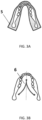
- the focal trough is a complex three-dimensional volume, and Figure 3A shows the profile of the focal trough (5) as compared to jaw dimensions.
- the required focal trough is achieved by rotating a gantry with X-ray source and X-detector around the patient's head with the center of rotation during the scan following a trajectory (6) schematically shown in Figure 3B . This trajectory is allowing for the best visualization of the average anatomy of the dento-maxillo-facial region.
- a method for processing a plurality of X-ray images of an object is known from US 2010/0246761A1 .
- This method comprises running an algorithm on a processor for shifting and adding corresponding pixel values from at least two different X-ray images to compose an image pixel in a panoramic image.
- US 2006/203959 A1 discloses a multi-layer dental panoramic and transverse X-ray imaging system that produces selectively dental panoramic X-ray images.
- This object is at least partially achieved with the method as defined in claim 1, which comprises the steps of using a shift-and-add method for generating a plurality of focal planes from the plurality of X-ray images, each focal plane being associated with a different area of the object, and using a focus stacking method for generating a two-dimensional (2D) image from the plurality of focal planes for generating a plurality of focal planes from the plurality of X-ray images acquired by the X-ray detector. Each focal plane is associated with a different area inside the object. A focus stacking method is then used for generating a 2D image from the plurality of focal planes.
- a shift-and-add method for generating a plurality of focal planes from the plurality of X-ray images, each focal plane being associated with a different area of the object
- a focus stacking method for generating a two-dimensional (2D) image from the plurality of focal planes for generating a plurality of focal planes from the plurality of X-
- the X-ray detector can be an area mode X-ray detector operating in continuous frame capture mode.
- Continuous frame capture mode means that the X-ray detector is continuously generating multiple X-ray images during the time the X-ray source emits X-rays at intervals of time defined by either internal circuitry or it is triggered so externally. This mode is known in the art.
- the X-ray source and X-ray detector are preferably kept at a fixed positional relationship with respect to each other during the obtaining of the plurality of the X-ray images. Furthermore, during the obtaining of the plurality of X-ray images, the X-ray source and X-ray detector are preferably moved, whereas the object is preferably kept stationary.
- the method may further comprise correcting a generated focal plane to account for scale distortion caused by a movement of a center of rotation of the combination of the X-ray source and X-ray detector during the movement thereof to produce a corrected focal plane.
- the trajectory of such center of rotation is for example illustrated in figure 3B .
- Using the shift-and-add method may comprise selecting a first image among said plurality of X-ray images, selecting a second image among said plurality of X-ray images different from the first image, shifting at least one of the first and second image with respect to the other of the first and second image, and, after having performed said shifting, adding the first and second images for constructing a focal plane.
- the method may comprise determining a first positional shift from a difference in mutual positioning of the X-ray detector, X-ray source, and the object at the time of recording the first and second image, determining a second positional shift or shifts that was/were applied during said shifting at least one of the first and second image, and associating an area inside the object with the focal plane that was generated using the first and second images based on the first and/or second positional shifts.
- Using a focus stacking method may comprise, for a given focal plane, determining a focused region in a focal plane that corresponds to a part of the area inside the object associated with that focal plane that is imaged in-focus in said focused region. Focused regions may be determined for each of the focal planes. These regions may be combined when generating said 2D image.
- the method may further comprise equaling a size of the focal planes at least in a direction where a shift of the underlying X-ray images has been applied during the shift-and-add method.
- the plurality of X-ray images from the X-ray detector can be stored in computer memory prior to performing the shift-and-add method and/or the focus stacking method.
- the method may further comprise using a depth map of respective areas that are in sharpness in respective focal planes for constructing a 3D model of the object.
- the depth map comprises, per pixel, depth information or other distance information pertaining to the distance between the X-ray detector and that part of the object that corresponds to the pixel in question. This distance information is obtained by applying the shift-and-add method.
- Each focal plane can be inspected for areas that are sharp.
- the image information of those areas e.g. grey values, can be used in conjunction to construct a 3D model.
- this model different pieces of the model of the object are obtained from different focal planes.
- the shift-and-add method and/or focus stacking method can be performed in real-time using a Graphic Processing Unit or any other dedicated computer hardware capable of processing images.
- the method may further comprise selective image processing of some areas of the focal planes before performing the focus stacking method, to control a depth-of-field (DOF) in the generated 2D image.
- the selective image may comprise blurring areas that do not correspond to a region of interest of the object. The contribution of the blurred areas in the various focal planes to the corresponding area in the final 2D image is therefore reduced compared to the contribution of the area in the focal plane that was selected as part of the focus stacking method, for forming the area in the final 2D image.
- a corresponding area is blurred in each of the focal planes, it becomes possible to ignore or discard such area altogether.
- the method may comprise associating a set of shift values to X-ray images among the plurality of X-ray images, shifting the individual X-ray images by their associated shift value, and adding the plurality of X-ray images after performing said shifting. Consequently, by shifting one X-ray image relative to another X-ray image, and by adding both images after shifting a focal plane, or part thereof, can be obtained. It should be noted that not each X-ray image among the plurality of images needs to be associated with a shift value as it is the relative shift that is important.
- the method may further comprise selecting the set of shift values for the shift-and-add method to achieve a non-uniform spatial density of the plurality of generated focal planes.
- a non-uniform spatial density refers to a non-uniform distribution of the focal planes over the distance between X-ray detector and object.
- the plurality of X-ray images may have been obtained using an X-ray source that emitted X-rays having an average X-ray energy that alternated between two or more selected fixed values, wherein the plurality of X-ray images comprises a plurality of subsets of X-ray images, each subset of X-ray images corresponding to one fixed value for the average X-ray energy.
- the method preferably further comprises performing the shift-and-add method and the focus stacking method for each subset of X-ray images separately to generate a respective 2D image. These respective images may be combined to generate a single 2D image.
- the plurality of X-ray images may be generated by an energy-discriminating X-ray detector.
- Bone and soft tissue show different absorption coefficients for different X-ray energies. Hence, by using a suitable X-ray energy either the bone or the soft tissue can be imaged accurately. By using the subsets as described above it becomes possible to combine the information from both the bone and soft tissue in a single 2D image.
- the invention provides an X-ray system that comprises an X-ray source, an X-ray detector, and a moving unit for causing a relative movement between an object to be imaged and at least one of the X-ray detector and the X-ray source during a process of obtaining a plurality of X-ray images.
- the system further comprises an image processing unit, such as a GPU, configured to implement the method as described above for generating the 2D image from said plurality of X-ray images.
- the system may further comprise a mounting frame.
- the X-ray source and the X-ray detector may have a fixed positional relationship, wherein the X-ray system can be configured to, using the moving unit, move the object relative to the X-ray source and X-ray detector, which are kept stationary relative to the mounting frame.
- the X-ray system can be configured to, using the moving unit, move the X-ray source and X-ray detector relative to the object, which is kept stationary relative to the mounting frame.
- the system may further comprise a memory for storing the plurality of X-ray images from the X-ray detector prior to performing the shift-and-add method and/or the focus stacking method.
- the present invention provides a computer readable data carrier comprising instructions, which, when executed by an image processing unit, cause the implementation of the method as described above.
- X-ray imaging techniques predominantly use a cone-shaped X-ray beam.
- the reason is that practical sources of X-rays are X-ray tubes, which emit X-rays from a small area on the X-ray tube anode called the X-ray focal spot.
- the X-ray beam is conical there is a geometric magnification factor associated with a given X-ray setup. In most cases, it is advantageous to reduce the magnification factor as much as possible to avoid imaging artefacts like geometrical distortions and image blur caused by the finite X-ray tube focal spot size.
- the SID in the imaging setup is usually selected to be as large as possible for a given power of the X-ray tube, expected exposure times, radiation leakage and other practical considerations. This approach is typical for both scanning and area mode X-ray imaging applications.
- Certain X-ray detectors operate in TDI imaging mode by design, and the results of scanning X-ray examinations cannot be modified as the image of a single focal plane is outputted by the detector and it is being generated inside the detector in the analog domain. This situation is different for an area mode X-ray detector that is operating in continuous frame capture mode.
- the set of frames acquired from such detector during image acquisition can be digitally processed to generate multiple focal planes, using the shift-and-add method.
- the shift-and-add method constitutes in essence a ⁇ digital TDI' image reconstruction technique. Therefore, the term 'TDI' will be applied to both traditional analog and digital TDI imaging modes without distinction, except when it is important to the subject matter.
- the shift value used for the shift-and-add method does not need to correspond exactly to the size of a single pixel or integer number times this size. It also could be a fraction of the native X-ray detector pixel size.
- the choice of shift values for the shift-and-add method is equivalent to adjustments made to the analog TDI signal transfer speed to control the relative speed of signal movement over the detector image plane, i.e. the smaller the shift value, the slower equivalent speed of object movement will be captured by the generated image and the closer the generated focal plane will be in space to the X-ray detector. This also implies that by varying the shift value it is possible to control the position of the corresponding focal plane over the SID.
- multiple focal planes can be generated from the same original set of X-ray images from the X-ray detector by varying the shift value for shift-and-add method.
- Generation or reconstruction of multiple focal planes from the same set of image data could substantially improve image quality and add valuable functionality in many X-ray imaging applications, examples of which will be provided below.
- the invention is however not limited to these applications.
- One of the X-ray imaging applications where the method of this invention could improve the quality of X-ray examination is dental panoramic X-ray imaging.
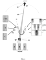
- Figure 4 shows the principle of reconstructing multiple tomographic planes for an X-ray panoramic application using a circular geometry, which is chosen for simplicity.
- a gantry with an X-ray detector (11) and X-ray source (10) orbits the patient's head (12) at constant speed.
- the X-ray source (10) emits a narrow beam (13) of X-rays, which is captured by the X-ray detector (11).
- the X-ray detector (11) is operating in continuous frame capture mode at constant frame rate, producing a 'movie' M of X-ray images A, B, C, and so forth.
- multiple focal planes I_FP1-I_FP3 are produced using the shift-and-add method with different shift values.
- Figure 4 shows the dependence of the position for generated focal planes FP1, FP2, and FP3, on the shift value (not to scale).
- a focal plane closer to X-ray source (10) requires a large shift value to be applied to the underlying X-ray images A, B, C, in order to generate the corresponding focal plane as features in this plane have higher relative speed of moving over the X-ray detector plane than the other shown planes.
- the in-focus image contents in the focal planes at different distances from the X-ray source exhibit different magnification
- the position of the focal plane over the SID defines the magnification.
- the single parameter that defines said position of the focal plane (FPn) over the SID in a simplified geometry as shown in Figure 4 , is the shift value of the shift-and-add method used for reconstructing said focal plane. Therefore, the focal planes could be re-sized to the same magnification in digital domain, based solely on the respective shift values used in the shift-and-add method.
- Equipment for panoramic X-ray imaging exhibits a variety of system architecture decisions to enable panoramic imaging. Actual machines could be substantially different in the way the image acquisition is implemented. The type of orbital movement, detector frame rate, pixel size, detector orientation, SID, distance of X-ray detector from the patient, scanning time, could differ. These and other system level decisions will determine how many tomographic slices at which spacing will be required to generate a satisfactory panoramic X-ray image.
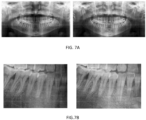
- Figure 7 shows panoramic images of a dental skull phantom produced from the same set of frames captured by an area mode X-ray detector in a commercial panoramic imaging system. The image on the left is produced by an existing technique of reconstructing the panoramic image using the assumption of average patient anatomy, while the image on the right is produced using the method of this invention. Both images show very good sharpness and a high degree of similarity otherwise.
- Figure 7B provides a zoomed view on the anterior region of the images in Figure 7A . It can be seen that reconstruction using the method of this invention overcomes a slight misplacement of the phantom, and captures details of the front teeth with better resolution than the standard reconstruction technique. It is important to note that the image on the right in Figure 7B , corresponding to the figure on the right in Figure 7A , is produced without using any actual information regarding SID, X-ray detector frame rate, acquisition time, etc. from the dental X-ray system. The only assumption used in reconstruction is that both orbital mechanical movement and detector frame rate were kept constant during image acquisition.
- An additional benefit of the method of this invention in panoramic imaging applications, potentially simplifying the design of future dental panoramic systems, is that the large DOF provided by a synthetic 2D image produced by focus stacking of the generated focal planes removes the need for movement of the center of rotation of the gantry with the X-ray source and X-ray detector, enabling significant reductions in cost and complexity of the dental X-ray system.
- Simple circular rotation of the gantry will produce geometrical distortion caused by differences in magnification for anterior and posterior teeth, which can still be effectively corrected in the digital domain during post-processing of the image.
- Figure 8A and 8B show the approximate position of the focus trough for a panoramic imaging modality, or the DOF in more generic terms, using the method of this invention for producing a 2D panoramic image for a simple circular geometry ( Figure 8A ) and an industry standard gantry rotation ( Figure 8B ).
- the area of the focus trough expands over the minimum required area as shown in Figure 3A . This expansion does not add any new features to the panoramic image, as the added areas contain only soft tissue not visible in the panoramic X-ray image because of the relatively hard spectrum of the panoramic X-ray beam that reaches the X-ray detector.
- the reduction or any other change to the shape or a position of the DOF can be achieved by intentional image blurring in the respective areas of relevant focal planes in the generated stack of focal planes.
- the focus stacking procedure will omit information from these areas and the resulting DOF will exclude the locations in the volume occupied by the processed areas.
- Said blurring could be achieved by, for example, applying a Gaussian blur filter or any other low pass image filtering method.
- the method of the invention produces a tomography image stack, in which image coordinates can be calculated to correspond precisely to spatial coordinates.
- cephalometry which is the analysis of the dental and skeletal relationships in a human head
- the current approach for cephalometry is to use a large SID up to 2 meters in order to reduce the difference in magnification ratios at the front and the back of a human head. This allows for a cephalometric X-ray image to be obtained that can be used for measurement of angles, distances, etc., for the purpose of planning the targeted treatment.
- Modern dental equipment enables cephalometric imaging in dedicated versions of dental X-ray systems only, and these require a substantially larger working space in the X-ray room compared to panoramic-only X-ray systems.
- the method of this invention will allow for generating a cephalometric image using a similarly compact system geometry as used for panoramic imaging.
- mammography Another medical X-ray application that could benefit from the method of this invention is mammography.
- a current trend in mammography is the growing proliferation of Digital Breast Tomosynthesis (DBT), which promises a noticeable increase in sensitivity, i.e. the ability to detect objects inside the breast, and specificity, i.e. the ability to classify detected objects into malignant or benign classes, over traditional 2D X-ray mammography.
- DBT Digital Breast Tomosynthesis
- Primary objects of interest for X-ray mammography are either large areas exhibiting a small contrast difference to normal glandular tissues, i.e. tumors, or objects with high contrast and dimensions smaller than or comparable to the X-ray detector pixel size, i.e. calcifications.
- the mammography diagnostic system should exhibit excellent contrast sensitivity to enable positive identification and further classification of these objects of interest by a trained radiologist.
- the X-ray beam attenuation is higher than typical and objects of interest show reduced visibility when using traditional mammography techniques. This increases the false negatives diagnostics rate, and results in an increase in missed malignant cancers.
- the DBT technique requires the acquisition of multiple images at different angles of incidence of the X-ray beam while the breast and X-ray detector are held static. Because the internal structure of the breast is observed at different angles, the detectability of objects inside the breast is improved.
- a DBT stack of slices is generated from the totality of acquired individual images at different angles and presented to the radiologist as a stack of slices for individual review. This is often accompanied by a single synthetic 2D image containing a 'summary' of objects of interest from all slices.
- This invention significantly improves the way the DBT procedure is executed. From a single scan of a breast with an area mode X-ray detector operating in continuous frame capture mode, the full tomosynthesis stack of slices can be generated. System image acquisition and image generation for a DBT system utilizing the method of this invention will not be different from the description of the panoramic X-ray modality.
- the narrow DOF of X-ray detectors operating in TDI mode limits their use to niche applications.
- An example of narrow DOF applications like this is X-ray PCB solder inspection.
- the area of interest is a shallow plane and the TDI DOF is adequate for the imaging requirements in this application.
- Figures 9A-9C illustrate the image quality improvements when applying the method according to the invention for the case of conveyer belt applications.
- the object for examination was a cardboard box approximately 20cm high and filled with different objects.
- the transportation system allowed for linear movement of the object in relation to a stationary X-ray source and X-ray detector, while the X-ray detector was operating in continuous frame capture mode.
- Figure 9 (left) and Figure 9 (middle) show the imaging results when the TDI focal plane is at the bottom and at the top of the box, respectively. It is obvious that the narrow DOF of a standard TDI operation makes it impossible to reveal the contents of the box with adequate overall sharpness.
- the image in Figure 9 (right) shows the synthetic 2D image from a tomographic stack of 19 images, generated in accordance with the present invention using the same data as used to generate the images in Figures 9 (left) and (right). All of the objects in the image in Figure 9 (right) are in focus and are easily recognizable as the DOF for this experiment has been effectively increased to 20cm.
- All embodiments above are provided for imaging modes using a poly-energetic X-ray beam, and X-ray detectors generating an output signal proportional to the total amount of energy captured by the pixel.
- Substantially higher information content can generally be produced by X-ray images where the X-ray setup is capable of energy discrimination. Additional information from spectrum changes for the object under study provides means to differentiate between various materials or differences in composition of the object, as well as increases the dynamic range of the X-ray images.
- the proposed method of this invention is not dependent on the technology for X-ray capture in the X-ray detector, and therefore is in general compatible with dual energy and energy discrimination principles of X-ray imaging using energy discrimination at detector level.
- Another method of dual-energy imaging can be realized by imaging with alternating X-ray tube high voltage.
- An example of such application is Contrast Enhanced Digital Mammography (CEDM), where the difference between two breast images taken each having different high voltage settings applied to the X-ray tube is evaluated. Images are taken within quick succession with contrast agent injected into the breast before the examination. Using the method of this invention would allow performing contrast enhanced DBT, which is beyond the capabilities of any of commercial DBT system currently on the market.
- CEDM Contrast Enhanced Digital Mammography
- the method of the invention allows the use of the generated 2D and 3D images for performing measurements of distances, angles, etcetera between the visualized features of the object with high precision, e.g. for biometrical purposes.
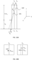
- Figures 10A and 10B illustrate the known principle of the shift-and-add method that is used in the present invention.
- the X-ray source and X-ray detector have a fixed mutual positioning and are moved between two positions relative to an object having internal features A and B. More in particular, the X-ray source is at a position S 1 when recording a first image, depicted on the left in Figure 10B , and at a position S 2 when recording a second image depicted on the right in Figure 10B .
- Figure 10A illustrates two center lines C 1 , C 2 that represent the center line of the X-ray detector at the time of recording image 1 and image 2, respectively.
- the movement of the X-ray detector and X-ray source is such that a distance between feature A of the object and the X-ray detector remains at value h 1 , whereas a distance between feature A of the object and the X-ray source, or at least a line on which the X-ray source moves, is denoted by h-h 1 .
- h denotes the source to image distance (SID).
- Line 101 indicates an X-ray that is emitted by the X-ray source at position S 1 and which passes through features A and B inside the object to be imaged. Consequently, in image 1 these features will appear at the same position in the image.
- Line 102 indicates an X-ray that is emitted by the X-ray source at position S 2 and which passes through feature A inside the object to be imaged. As can be seen, line 102 does not pass through feature B. Consequently, in image 2 these features will not appear at the same position in the image.
- Figure 10A illustrates that feature A is at a distance h 1 relative to the X-ray detector.
- d 1 /h 1 d/(h-h 1 ).
- d 2 /h 1 (d+dy)/(h-h 1 ).
- a new image can be constructed by using images 1 and 2, wherein the positional shift is compensated for.
- the pixel value of image 1 at position (x,y) could be added to the pixel value of image 2 at position (x, y+D).
- Such image is referred to as a focal plane.
- a plurality of focal planes can be calculated for various values of z. This allows focused information to be obtained for different positions z inside the object. These focal planes can be used for generating a final image using a focus stacking method.
Landscapes
- Physics & Mathematics (AREA)
- Engineering & Computer Science (AREA)
- General Physics & Mathematics (AREA)
- Theoretical Computer Science (AREA)
- Computer Graphics (AREA)
- Geometry (AREA)
- Software Systems (AREA)
- Apparatus For Radiation Diagnosis (AREA)
Description
- The present invention relates to a method for processing a plurality of X-ray images of an object that have been obtained using an X-ray source and an X-ray detector, wherein each of the images corresponds to a different positioning of the X-ray source, the X-ray detector, and the object relative to each other. The invention further relates to an X-ray system comprising an image processing unit configured to implement this method.
- X-ray imaging is widely employed in a wide variety of applications. For example, it is used for diagnosing human health conditions, referred to as medical X-ray imaging, for diagnosing animal health conditions, referred to as veterinary X-ray imaging, for assisting quality control measures in manufacturing and producing goods, referred to as industrial X-ray imaging, for ensuring safe transportation of goods and people, referred to as security X-ray imaging, and many other applications.
- X-ray detectors could be designed following different architectures. One of the architectures of an X-ray detector is a line-scan X-ray detector. In such detectors, the X-ray sensitive elements (pixels) are set up in an N × 1 matrix as in
Figure 1A , where the position of each pixel is indicated in between parentheses. A different architecture of X-ray detectors is an area X-ray detector. Pixels in an area X-ray detector are arranged in an N × M matrix as inFigure 1B , where the position of each pixel in the matrix is indicated in between parentheses. In both cases, signals from X-ray detector pixels of the X-ray detector are read out by internal or external pixel read-out circuitry, processed and outputted in a format which is specific for the application or design of the detector or both. - In a typical geometry for X-ray imaging, the Source-to-Image Distance (SID) for both area and line-scan X-ray detectors is large compared to the X-ray focal spot size. Such imaging setup typically exhibits a large Depth-of-Field (DOF). This means that the position of the imaged object over the SID has little impact on the sharpness of the image.
- A large DOF comes with a drawback, as the X-ray images from the X-ray detectors are not preserving the relative scale of objects or the object's internal features. That happens because almost all X-ray sources are producing a diverging X-ray beam, which results in a 'projection-imaging' geometry of objects. As a result, a small object close to the X-ray tube could appear larger in the image compared to a physically larger object that is positioned closer to the X-ray detector.
- Visible light imaging applications, such as for example in-line quality control, LCD inspection or semiconductor mask and wafer inspection, often use area mode detectors in a special way that simulates line-scan operation, called Time Delay and Integration (TDI), see
Figure 2 . In TDI mode, the signal integration is not static during the integration time, and the image, which is captured through a lens (2) and which is integrated, is moved over detector (1) synchronously with the movement indicated by arrow (3) of object (4). In this way, the exposure time is increased many times over the exposure of a single pixel and very low light intensity scenes can be imaged with high resolution and much improved Signal-to-Noise Ratio (SNR). The mentioned image movement is typically made by one row of pixels at a time. Therefore, the output signal is electrically equivalent to operation of a line-scan detector. The benefits of the TDI mode of operation in visible light imaging applications are only realized if the speed of detector operation and the speed of object movement are precisely synchronized. When these movements are not properly synchronized, the imaging result is usually not satisfactory. - The TDI principle is also applicable to X-ray imaging. For example, an area mode X-ray detector can be operated in TDI mode and the sensitivity and SNR will be many times higher compared to a line-scan X-ray detector of the same native pixel size. Different to a visible light TDI imaging mode, a mismatch between the speed of TDI operation and the movement of the object in X-ray imaging does not necessarily result in absent image content. As X-rays have the capability to penetrate matter, the area within the object with the same linear speed of movement as that of the image in the detector image plane will be in focus in the X-ray image. Such area is called a 'linear tomography focal plane', hereinafter sometimes abbreviated to `focal plane'.
- The phenomenon described above is used in X-ray imaging applications to produce focused images of selected areas inside the object and the technique is called linear tomography. Because linear tomography limits in-focus imaging of the object features to the focal plane only, it reduces the DOF compared to a conventional area mode detector using the same X-ray setup geometry. This feature could be useful in medical or dental X-ray applications where the goal of imaging is to discriminate between object features, which normally would be superimposed in a conventional X-ray image. The best example of such an application is dental panoramic X-ray imaging. The anatomic complexity of the dento-maxillo-facial region of the human head makes visualization of areas of interest inherently difficult.
- From its origins in the early 1960s, dental panoramic X-ray imaging has relied on the linear tomography principle to produce diagnostic images. In a typical panoramic X-ray system, the X-ray source and X-ray detector have a fixed mutual positioning, e.g. they are both mounted on an opposite end of an X-ray system gantry, and are rotated around the patient's head. Beginning from the late 1990s, panoramic imaging adopted digital imaging technology but still relied on the linear tomography principle for creating 'unobstructed views' of upper and lower jaw and dentition.
- In general, there are many features of human head anatomy expected to be visible in a panoramic X-ray image. The volume that includes these features is called the focal trough. The focal trough is a complex three-dimensional volume, and
Figure 3A shows the profile of the focal trough (5) as compared to jaw dimensions. Typically the required focal trough is achieved by rotating a gantry with X-ray source and X-detector around the patient's head with the center of rotation during the scan following a trajectory (6) schematically shown inFigure 3B . This trajectory is allowing for the best visualization of the average anatomy of the dento-maxillo-facial region. Moreover, this trajectory and some other system level arrangements results in an acceptable positioning of the focal trough as well as reduced scale distortions in the panoramic X-ray image. In actual dental practice, either because of errors in patient positioning or actual patient anatomy deviating from the assumed average anatomy pre-programmed into the machine operation, the narrow DOF of linear tomography often results in actual focus trough missing the proper position against the features of patient's anatomy. This causes reduced sharpness in areas of interest in the panoramic X-ray image. - A method for processing a plurality of X-ray images of an object is known from
US 2010/0246761A1 . This method comprises running an algorithm on a processor for shifting and adding corresponding pixel values from at least two different X-ray images to compose an image pixel in a panoramic image. -
US 2006/203959 A1 discloses a multi-layer dental panoramic and transverse X-ray imaging system that produces selectively dental panoramic X-ray images. - It is an object of the invention to provide a method for generating a panoramic image with improved sharpness, the panoramic image preferably having a DOF that includes all or as many variations in anatomy of the patient in one standard setting without any individual patient-specific adjustments.
- This object is at least partially achieved with the method as defined in
claim 1, which comprises the steps of using a shift-and-add method for generating a plurality of focal planes from the plurality of X-ray images, each focal plane being associated with a different area of the object, and using a focus stacking method for generating a two-dimensional (2D) image from the plurality of focal planes for generating a plurality of focal planes from the plurality of X-ray images acquired by the X-ray detector. Each focal plane is associated with a different area inside the object. A focus stacking method is then used for generating a 2D image from the plurality of focal planes. - The shift-and-add method and the focus stacking method are known in isolation from the prior art. The applicant has found that by combining these two known methods, the quality of the resulting 2D X-ray image can be improved considerably when compared to the prior art approaches.
- The X-ray detector can be an area mode X-ray detector operating in continuous frame capture mode. Continuous frame capture mode means that the X-ray detector is continuously generating multiple X-ray images during the time the X-ray source emits X-rays at intervals of time defined by either internal circuitry or it is triggered so externally. This mode is known in the art.
- The X-ray source and X-ray detector are preferably kept at a fixed positional relationship with respect to each other during the obtaining of the plurality of the X-ray images. Furthermore, during the obtaining of the plurality of X-ray images, the X-ray source and X-ray detector are preferably moved, whereas the object is preferably kept stationary.
- The method may further comprise correcting a generated focal plane to account for scale distortion caused by a movement of a center of rotation of the combination of the X-ray source and X-ray detector during the movement thereof to produce a corrected focal plane. The trajectory of such center of rotation is for example illustrated in
figure 3B . - Using the shift-and-add method may comprise selecting a first image among said plurality of X-ray images, selecting a second image among said plurality of X-ray images different from the first image, shifting at least one of the first and second image with respect to the other of the first and second image, and, after having performed said shifting, adding the first and second images for constructing a focal plane. Furthermore, the method may comprise determining a first positional shift from a difference in mutual positioning of the X-ray detector, X-ray source, and the object at the time of recording the first and second image, determining a second positional shift or shifts that was/were applied during said shifting at least one of the first and second image, and associating an area inside the object with the focal plane that was generated using the first and second images based on the first and/or second positional shifts.
- Using a focus stacking method may comprise, for a given focal plane, determining a focused region in a focal plane that corresponds to a part of the area inside the object associated with that focal plane that is imaged in-focus in said focused region. Focused regions may be determined for each of the focal planes. These regions may be combined when generating said 2D image.
- The method may further comprise equaling a size of the focal planes at least in a direction where a shift of the underlying X-ray images has been applied during the shift-and-add method.
- The plurality of X-ray images from the X-ray detector can be stored in computer memory prior to performing the shift-and-add method and/or the focus stacking method.
- The method may further comprise using a depth map of respective areas that are in sharpness in respective focal planes for constructing a 3D model of the object. The depth map comprises, per pixel, depth information or other distance information pertaining to the distance between the X-ray detector and that part of the object that corresponds to the pixel in question. This distance information is obtained by applying the shift-and-add method.
- Each focal plane can be inspected for areas that are sharp. The image information of those areas, e.g. grey values, can be used in conjunction to construct a 3D model. In this model, different pieces of the model of the object are obtained from different focal planes.
- The shift-and-add method and/or focus stacking method can be performed in real-time using a Graphic Processing Unit or any other dedicated computer hardware capable of processing images.
- The method may further comprise selective image processing of some areas of the focal planes before performing the focus stacking method, to control a depth-of-field (DOF) in the generated 2D image. For instance, the selective image may comprise blurring areas that do not correspond to a region of interest of the object. The contribution of the blurred areas in the various focal planes to the corresponding area in the final 2D image is therefore reduced compared to the contribution of the area in the focal plane that was selected as part of the focus stacking method, for forming the area in the final 2D image. Alternatively, if a corresponding area is blurred in each of the focal planes, it becomes possible to ignore or discard such area altogether.
- The method may comprise associating a set of shift values to X-ray images among the plurality of X-ray images, shifting the individual X-ray images by their associated shift value, and adding the plurality of X-ray images after performing said shifting. Consequently, by shifting one X-ray image relative to another X-ray image, and by adding both images after shifting a focal plane, or part thereof, can be obtained. It should be noted that not each X-ray image among the plurality of images needs to be associated with a shift value as it is the relative shift that is important.
- The method may further comprise selecting the set of shift values for the shift-and-add method to achieve a non-uniform spatial density of the plurality of generated focal planes. A non-uniform spatial density refers to a non-uniform distribution of the focal planes over the distance between X-ray detector and object.
- The plurality of X-ray images may have been obtained using an X-ray source that emitted X-rays having an average X-ray energy that alternated between two or more selected fixed values, wherein the plurality of X-ray images comprises a plurality of subsets of X-ray images, each subset of X-ray images corresponding to one fixed value for the average X-ray energy. In this case, the method preferably further comprises performing the shift-and-add method and the focus stacking method for each subset of X-ray images separately to generate a respective 2D image. These respective images may be combined to generate a single 2D image. Furthermore, the plurality of X-ray images may be generated by an energy-discriminating X-ray detector.
- Bone and soft tissue show different absorption coefficients for different X-ray energies. Hence, by using a suitable X-ray energy either the bone or the soft tissue can be imaged accurately. By using the subsets as described above it becomes possible to combine the information from both the bone and soft tissue in a single 2D image.
- According to a further aspect, the invention provides an X-ray system that comprises an X-ray source, an X-ray detector, and a moving unit for causing a relative movement between an object to be imaged and at least one of the X-ray detector and the X-ray source during a process of obtaining a plurality of X-ray images. The system further comprises an image processing unit, such as a GPU, configured to implement the method as described above for generating the 2D image from said plurality of X-ray images.
- The system may further comprise a mounting frame. Furthermore, the X-ray source and the X-ray detector may have a fixed positional relationship, wherein the X-ray system can be configured to, using the moving unit, move the object relative to the X-ray source and X-ray detector, which are kept stationary relative to the mounting frame. Alternatively, the X-ray system can be configured to, using the moving unit, move the X-ray source and X-ray detector relative to the object, which is kept stationary relative to the mounting frame.
- The system may further comprise a memory for storing the plurality of X-ray images from the X-ray detector prior to performing the shift-and-add method and/or the focus stacking method.
- According to a further aspect, the present invention provides a computer readable data carrier comprising instructions, which, when executed by an image processing unit, cause the implementation of the method as described above.
- Next, the invention will be described in more detail by referring to the appended drawings, wherein:
-
Figure 1 presents two known configurations for X-ray detectors; -
Figure 2 illustrates the concept of linear tomography; -
Figure 3A and 3B illustrate the focal trough; -
Figure 4 illustrates the application of the shift-and-add method for generating a plurality of focal planes in correspondence with the present invention; -
Figure 5 illustrates an example of a dental panoramic image; -
Figure 6 illustrates the correction of a focal plane for spatial distortions; -
Figures 7A and 7B illustrate a comparison between dental panoramic images obtained using a prior art approach and an approach in accordance with the present invention; -
Figure 8A and 8B illustrate the dental focal trough in accordance with the present invention; -
Figure 9 illustrates an application of the invention for security; and -
Figures 10A and 10B illustrate the principle of the shift-and-add method. - X-ray imaging techniques predominantly use a cone-shaped X-ray beam. The reason is that practical sources of X-rays are X-ray tubes, which emit X-rays from a small area on the X-ray tube anode called the X-ray focal spot. Because the X-ray beam is conical there is a geometric magnification factor associated with a given X-ray setup. In most cases, it is advantageous to reduce the magnification factor as much as possible to avoid imaging artefacts like geometrical distortions and image blur caused by the finite X-ray tube focal spot size. To realize such, the SID in the imaging setup is usually selected to be as large as possible for a given power of the X-ray tube, expected exposure times, radiation leakage and other practical considerations. This approach is typical for both scanning and area mode X-ray imaging applications.
- Even if the magnification factor of the X-ray imaging setup is small, it still impacts the imaging results in linear tomography imaging with a TDI-mode detector. As mentioned above, only the object area, which has the same linear speed of moving over the detector image plane as the speed of TDI signal transfer, will be imaged in focus. This could result in only a part of the object being captured in focus in the TDI X-ray image.
- Certain X-ray detectors operate in TDI imaging mode by design, and the results of scanning X-ray examinations cannot be modified as the image of a single focal plane is outputted by the detector and it is being generated inside the detector in the analog domain. This situation is different for an area mode X-ray detector that is operating in continuous frame capture mode. The set of frames acquired from such detector during image acquisition can be digitally processed to generate multiple focal planes, using the shift-and-add method. The shift-and-add method constitutes in essence a `digital TDI' image reconstruction technique. Therefore, the term 'TDI' will be applied to both traditional analog and digital TDI imaging modes without distinction, except when it is important to the subject matter. The shift value used for the shift-and-add method does not need to correspond exactly to the size of a single pixel or integer number times this size. It also could be a fraction of the native X-ray detector pixel size. The choice of shift values for the shift-and-add method is equivalent to adjustments made to the analog TDI signal transfer speed to control the relative speed of signal movement over the detector image plane, i.e. the smaller the shift value, the slower equivalent speed of object movement will be captured by the generated image and the closer the generated focal plane will be in space to the X-ray detector. This also implies that by varying the shift value it is possible to control the position of the corresponding focal plane over the SID. According to the invention, multiple focal planes can be generated from the same original set of X-ray images from the X-ray detector by varying the shift value for shift-and-add method. Generation or reconstruction of multiple focal planes from the same set of image data could substantially improve image quality and add valuable functionality in many X-ray imaging applications, examples of which will be provided below. The invention is however not limited to these applications.
- One of the X-ray imaging applications where the method of this invention could improve the quality of X-ray examination is dental panoramic X-ray imaging.
-
Figure 4 shows the principle of reconstructing multiple tomographic planes for an X-ray panoramic application using a circular geometry, which is chosen for simplicity. A gantry with an X-ray detector (11) and X-ray source (10) orbits the patient's head (12) at constant speed. The X-ray source (10) emits a narrow beam (13) of X-rays, which is captured by the X-ray detector (11). The X-ray detector (11) is operating in continuous frame capture mode at constant frame rate, producing a 'movie' M of X-ray images A, B, C, and so forth. - According to the invention, multiple focal planes I_FP1-I_FP3 are produced using the shift-and-add method with different shift values.
Figure 4 shows the dependence of the position for generated focal planes FP1, FP2, and FP3, on the shift value (not to scale). A focal plane closer to X-ray source (10) requires a large shift value to be applied to the underlying X-ray images A, B, C, in order to generate the corresponding focal plane as features in this plane have higher relative speed of moving over the X-ray detector plane than the other shown planes. - No single reconstructed focal plane captures all the required features of jaw anatomy in focus as the curvatures of the generated focal planes and the jaw profile are very different.
Figure 5 shows only a few focal planes reconstructed from digital data acquired by the X-ray detector. By changing the shift values for the shift-and-add method, a stack of focal planes can be reconstructed. Furthermore, the set of shift values for the shift-and-add method could be selected in the way the said stack of focal planes will fill in the volume occupied by the jaw with small spacing between the focal planes. An obvious inference to this is the fact that the image of interest is becoming 'distributed' over the totality of focal planes. According to the invention, in order to 'extract' a single panoramic X-ray image the totality of focal planes is processed using a focus stacking operation. An example of such an image is provided inFigure 5 . - As stated above, the in-focus image contents in the focal planes at different distances from the X-ray source exhibit different magnification, and the position of the focal plane over the SID defines the magnification. It could be trivially shown that the single parameter that defines said position of the focal plane (FPn) over the SID, in a simplified geometry as shown in
Figure 4 , is the shift value of the shift-and-add method used for reconstructing said focal plane. Therefore, the focal planes could be re-sized to the same magnification in digital domain, based solely on the respective shift values used in the shift-and-add method. - Because the rotation of the gantry in actual commercial panoramic X-ray machines is not circular, the method above will not fully compensate for differences in magnification for generated focal planes in practical imaging conditions and the panoramic image will show some scale distortions. For example, the front (anterior) teeth will be shown larger in scale compared to the teeth in the molar (posterior) jaw area.
Figure 6 shows how the original focal plane (top) could be digitally corrected for scale distortions caused by movement of the center of rotation of the X-ray console, i.e. the gantry with the X-ray source and X-ray detector, to produce a corrected focal plane (bottom). This additional scaling depends on the specific design of the panoramic machine, which is known or can be derived through a straightforward calibration routine. - It is important to recognize that this correction in the digital domain is not artificial and it achieves identical or similar results as other existing imaging techniques and algorithms for creating panoramic images. The reason is these other approaches are also compensating for magnification errors in the panoramic setup by other aspects of panoramic machine design, like the mechanical design of the rotating parts, X-ray detector frame rate, image reconstruction, etc. Any deviations of the actual anatomy of the patient from assumed curves of upper and lower jaws in these systems result in scale distortions in the traditional panoramic image too. Small amounts of scale distortions in panoramic X-ray images are acceptable in the dental industry, as X-ray panoramic images are not used for biometrical purposes. Dental OEMs typically put a disclaimer in the user documentation of their systems, stating that images are produced based on assumptions of standard or average anatomy of the patient.
- Equipment for panoramic X-ray imaging exhibits a variety of system architecture decisions to enable panoramic imaging. Actual machines could be substantially different in the way the image acquisition is implemented. The type of orbital movement, detector frame rate, pixel size, detector orientation, SID, distance of X-ray detector from the patient, scanning time, could differ. These and other system level decisions will determine how many tomographic slices at which spacing will be required to generate a satisfactory panoramic X-ray image.
Figure 7 shows panoramic images of a dental skull phantom produced from the same set of frames captured by an area mode X-ray detector in a commercial panoramic imaging system. The image on the left is produced by an existing technique of reconstructing the panoramic image using the assumption of average patient anatomy, while the image on the right is produced using the method of this invention. Both images show very good sharpness and a high degree of similarity otherwise. -
Figure 7B provides a zoomed view on the anterior region of the images inFigure 7A . It can be seen that reconstruction using the method of this invention overcomes a slight misplacement of the phantom, and captures details of the front teeth with better resolution than the standard reconstruction technique. It is important to note that the image on the right inFigure 7B , corresponding to the figure on the right inFigure 7A , is produced without using any actual information regarding SID, X-ray detector frame rate, acquisition time, etc. from the dental X-ray system. The only assumption used in reconstruction is that both orbital mechanical movement and detector frame rate were kept constant during image acquisition. - An additional benefit of the method of this invention in panoramic imaging applications, potentially simplifying the design of future dental panoramic systems, is that the large DOF provided by a synthetic 2D image produced by focus stacking of the generated focal planes removes the need for movement of the center of rotation of the gantry with the X-ray source and X-ray detector, enabling significant reductions in cost and complexity of the dental X-ray system. Simple circular rotation of the gantry will produce geometrical distortion caused by differences in magnification for anterior and posterior teeth, which can still be effectively corrected in the digital domain during post-processing of the image.
-
Figure 8A and 8B show the approximate position of the focus trough for a panoramic imaging modality, or the DOF in more generic terms, using the method of this invention for producing a 2D panoramic image for a simple circular geometry (Figure 8A ) and an industry standard gantry rotation (Figure 8B ). The area of the focus trough expands over the minimum required area as shown inFigure 3A . This expansion does not add any new features to the panoramic image, as the added areas contain only soft tissue not visible in the panoramic X-ray image because of the relatively hard spectrum of the panoramic X-ray beam that reaches the X-ray detector. Still, if the reduction or any other change to the shape or a position of the DOF is required, it can be achieved by intentional image blurring in the respective areas of relevant focal planes in the generated stack of focal planes. The focus stacking procedure will omit information from these areas and the resulting DOF will exclude the locations in the volume occupied by the processed areas. Said blurring could be achieved by, for example, applying a Gaussian blur filter or any other low pass image filtering method. - The method of the invention produces a tomography image stack, in which image coordinates can be calculated to correspond precisely to spatial coordinates. This means that another dental X-ray imaging application, cephalometry, which is the analysis of the dental and skeletal relationships in a human head, is also suitable for the application of the method of this invention. The current approach for cephalometry is to use a large SID up to 2 meters in order to reduce the difference in magnification ratios at the front and the back of a human head. This allows for a cephalometric X-ray image to be obtained that can be used for measurement of angles, distances, etc., for the purpose of planning the targeted treatment. Modern dental equipment enables cephalometric imaging in dedicated versions of dental X-ray systems only, and these require a substantially larger working space in the X-ray room compared to panoramic-only X-ray systems. The method of this invention will allow for generating a cephalometric image using a similarly compact system geometry as used for panoramic imaging.
- Another medical X-ray application that could benefit from the method of this invention is mammography. A current trend in mammography is the growing proliferation of Digital Breast Tomosynthesis (DBT), which promises a noticeable increase in sensitivity, i.e. the ability to detect objects inside the breast, and specificity, i.e. the ability to classify detected objects into malignant or benign classes, over traditional 2D X-ray mammography. Primary objects of interest for X-ray mammography are either large areas exhibiting a small contrast difference to normal glandular tissues, i.e. tumors, or objects with high contrast and dimensions smaller than or comparable to the X-ray detector pixel size, i.e. calcifications. In both cases, the mammography diagnostic system should exhibit excellent contrast sensitivity to enable positive identification and further classification of these objects of interest by a trained radiologist. In patients with dense breast tissue, the X-ray beam attenuation is higher than typical and objects of interest show reduced visibility when using traditional mammography techniques. This increases the false negatives diagnostics rate, and results in an increase in missed malignant cancers.
- The DBT technique requires the acquisition of multiple images at different angles of incidence of the X-ray beam while the breast and X-ray detector are held static. Because the internal structure of the breast is observed at different angles, the detectability of objects inside the breast is improved. A DBT stack of slices is generated from the totality of acquired individual images at different angles and presented to the radiologist as a stack of slices for individual review. This is often accompanied by a single synthetic 2D image containing a 'summary' of objects of interest from all slices.
- This invention significantly improves the way the DBT procedure is executed. From a single scan of a breast with an area mode X-ray detector operating in continuous frame capture mode, the full tomosynthesis stack of slices can be generated. System image acquisition and image generation for a DBT system utilizing the method of this invention will not be different from the description of the panoramic X-ray modality.
- As previously explained, the narrow DOF of X-ray detectors operating in TDI mode limits their use to niche applications. An example of narrow DOF applications like this is X-ray PCB solder inspection. In this case, the area of interest is a shallow plane and the TDI DOF is adequate for the imaging requirements in this application.
- Because of their large DOF and ability to image continuously while providing output imaging data in real time, the majority of scanning X-ray imaging is still performed using line-scan X-ray detectors. This invention eliminates the weaknesses of TDI X-ray imaging, and allows for upgrading from line-scan X-ray detectors to better performing X-ray imaging devices that offer a number of very substantial benefits in various application areas.
- Industrial and security X-ray inspection applications of continuously moving objects are currently almost exclusively using line-scan X-ray detectors. An example of such application is airport security baggage inspection. A large DOF is a critical performance requirement for this application and, in combination with the low cost of line-scan X-ray detectors, results in the dominant position of line-scan X-ray detectors in these types of applications. This invention overcomes the inherent DOF limitations of the otherwise advantageous TDI imaging principle, and makes it possible to upgrade the application with better performing imaging technology.
- Figures 9A-9C illustrate the image quality improvements when applying the method according to the invention for the case of conveyer belt applications. The object for examination was a cardboard box approximately 20cm high and filled with different objects. The transportation system allowed for linear movement of the object in relation to a stationary X-ray source and X-ray detector, while the X-ray detector was operating in continuous frame capture mode.
- As explained earlier, the speed control of TDI operation of the X-ray detector allows for adjustment of the position of TDI focal plane over the SID.
Figure 9 (left) andFigure 9 (middle) show the imaging results when the TDI focal plane is at the bottom and at the top of the box, respectively. It is obvious that the narrow DOF of a standard TDI operation makes it impossible to reveal the contents of the box with adequate overall sharpness. The image inFigure 9 (right) shows the synthetic 2D image from a tomographic stack of 19 images, generated in accordance with the present invention using the same data as used to generate the images inFigures 9 (left) and (right). All of the objects in the image inFigure 9 (right) are in focus and are easily recognizable as the DOF for this experiment has been effectively increased to 20cm. - All embodiments above are provided for imaging modes using a poly-energetic X-ray beam, and X-ray detectors generating an output signal proportional to the total amount of energy captured by the pixel. Substantially higher information content can generally be produced by X-ray images where the X-ray setup is capable of energy discrimination. Additional information from spectrum changes for the object under study provides means to differentiate between various materials or differences in composition of the object, as well as increases the dynamic range of the X-ray images. The proposed method of this invention is not dependent on the technology for X-ray capture in the X-ray detector, and therefore is in general compatible with dual energy and energy discrimination principles of X-ray imaging using energy discrimination at detector level.
- Another method of dual-energy imaging can be realized by imaging with alternating X-ray tube high voltage. An example of such application is Contrast Enhanced Digital Mammography (CEDM), where the difference between two breast images taken each having different high voltage settings applied to the X-ray tube is evaluated. Images are taken within quick succession with contrast agent injected into the breast before the examination. Using the method of this invention would allow performing contrast enhanced DBT, which is beyond the capabilities of any of commercial DBT system currently on the market.
- In general, the method of the invention allows the use of the generated 2D and 3D images for performing measurements of distances, angles, etcetera between the visualized features of the object with high precision, e.g. for biometrical purposes.
-
Figures 10A and 10B illustrate the known principle of the shift-and-add method that is used in the present invention. InFigure 10A , the X-ray source and X-ray detector have a fixed mutual positioning and are moved between two positions relative to an object having internal features A and B. More in particular, the X-ray source is at a position S1 when recording a first image, depicted on the left inFigure 10B , and at a position S2 when recording a second image depicted on the right inFigure 10B . Similarly,Figure 10A illustrates two center lines C1, C2 that represent the center line of the X-ray detector at the time ofrecording image 1 andimage 2, respectively. InFigure 10A , the movement of the X-ray detector and X-ray source is such that a distance between feature A of the object and the X-ray detector remains at value h1, whereas a distance between feature A of the object and the X-ray source, or at least a line on which the X-ray source moves, is denoted by h-h1. Here, h denotes the source to image distance (SID). -
Line 101 indicates an X-ray that is emitted by the X-ray source at position S1 and which passes through features A and B inside the object to be imaged. Consequently, inimage 1 these features will appear at the same position in the image. -
Line 102 indicates an X-ray that is emitted by the X-ray source at position S2 and which passes through feature A inside the object to be imaged. As can be seen,line 102 does not pass through feature B. Consequently, inimage 2 these features will not appear at the same position in the image. -
Figure 10A illustrates that feature A is at a distance h1 relative to the X-ray detector. Using conventional geometry, one can deduce that d1/h1=d/(h-h1). The offset between C1 and feature A inimage 1, which equals the offset between C1 and feature B inimage 1, is denoted by OA,B,1 and can be calculated using OA,B,1=d+d1=(h/(h-h1)) × d. - Using conventional geometry, one can also deduce that d2/h1=(d+dy)/(h-h1). The offset between C2 and feature A in
image 2 is denoted by OA,2 and can be calculated using OA,2=dy+d+d2=(h/(h-h1)) x d + (h/(h-h1)) × dy. - Comparing
images - According to the invention, a new image can be constructed by using
images image 1 at position (x,y) could be added to the pixel value ofimage 2 at position (x, y+D). In this manner, an image will be obtained wherein features of the object in the plane defined by z=h1 will be in focus and wherein other features are blurred. Such image is referred to as a focal plane. - A plurality of focal planes can be calculated for various values of z. This allows focused information to be obtained for different positions z inside the object. These focal planes can be used for generating a final image using a focus stacking method.
- From the equation D = OA,B,1 - OA,2 = (h/(h-h1)) × dy stated above, it can be concluded that if the focal plane corresponds to an area inside the object close to the X-ray source, i.e. h1 approaches h, D will become very large. On the other hand, if the focal plane corresponds to an area inside the object close to the X-ray detector, D will approach dy.
- Although the invention is explained using detailed embodiments thereof, the skilled person readily understands that various modifications are possible without deviating from the scope that is defined by the appended claims.
Claims (15)
- A computer-implemented method for processing a plurality of X-ray images of an object that have been obtained using an X-ray source and an X-ray detector, wherein each of the images corresponds to a different positioning of the X-ray source, the X-ray detector, and the object relative to each other, the method comprising:using a shift-and-add method for generating a plurality of focal planes from the plurality of X-ray images, each focal plane being associated with a different area inside the object; andusing a focus stacking method for processing the totality of focal planes in order to generate a single 2D panoramic image, wherein said using a focus staking method comprises, for a given focal plane, determining a focused region in a focal plane that corresponds to a part of the area inside the object associated with that focal plane that is imaged in-focus in said focused region, wherein focused regions are determined for each of the focal planes, and wherein the focused regions are combined when generating said 2D panoramic image.
- The method according to claim 1, wherein said using a shift-and-add method comprises:reconstructing a stack of focal planes by changing shift values for the shift-and-add method; andselecting a set of shift values for the shift-and-add method such that the stack of focal planes fills in the volume occupied by the object with small spacing between the focal planes.
- The method according to claim 1 or 2, wherein the X-ray detector is an area mode X-ray detector operating in continuous frame capture mode.
- The method according to any of the previous claims, wherein the X-ray source and X-ray detector were kept at a fixed positional relationship with respect to each other during said obtaining of the plurality of the X-ray images.
- The method according to claim 4, wherein, during said obtaining of the plurality of X-ray images, the X-ray source and X-ray detector were moved, and the object was kept stationary;
preferably further comprising digitally correcting a generated focal plane to account for scale distortion caused by a movement of a center of rotation of the combination of the X-ray source and X-ray detector during the movement thereof to produce a corrected focal plane. - The method according to any of the previous claims, further comprising equaling a size of the focal planes at least in a direction where a shift of the underlying X-ray images has been applied during the shift-and-add method.
- The method according to any of the previous claims, further comprising storing the plurality of X-ray images from the X-ray detector in computer memory prior to performing the shift-and-add method and/or the focus stacking method.
- The method according to any of the previous claims, further comprising using a depth map of respective areas that are in sharpness in respective focal planes for constructing a 3D model of the object.
- The method according to any of the previous claims, wherein the shift-and-add method and/or focus stacking method is performed in real-time using a Graphic Processing Unit or any other dedicated computer hardware capable of processing images.
- The method according to any of the previous claims, further comprising selective image processing of some areas of the focal planes before performing the focus stacking method, to control a depth-of-field (DOF) in the generated 2D panoramic image, wherein said selective image processing of some areas of the focal planes before performing the focus stacking method preferably comprises blurring areas that do not correspond to a region of interest of the object.
- The method according to any of the previous claims, comprising associating a set of shift values to X-ray images among the plurality of X-ray images, shifting the individual X-ray images by their associated shift value, and adding the plurality of X-ray images after performing said shifting, the method preferably further comprises selecting the set of shift values for the shift-and-add method to achieve a non-uniform spatial density of the plurality of generated focal planes.
- The method according to any of the previous claims, wherein the plurality of X-ray images have been obtained using an X-ray source that emitted X-rays having an X-ray energy distribution that alternated between two or more different distributions, wherein the plurality of X-ray images comprises a plurality of subsets of X-ray images, each subset of X-ray images corresponding to one particular X-ray energy distribution, the method further comprising performing the shift-and-add method and the focus stacking method for each subset of X-ray images separately to generate a respective 2D panoramic image, the method preferably further comprises generating a single 2D panoramic image from the respective 2D panoramic images.
- An X-ray system, comprising:an X-ray source;an X-ray detector;a moving unit for causing a relative movement between an object to be imaged and at least one of the X-ray detector and the X-ray source during a process of obtaining a plurality of X-ray images;an image processing unit configured to implement the method as defined in any of the previous claims.
- The X-ray system according to claim 13, further comprising a mounting frame, wherein the X-ray source and the X-ray detector have a fixed positional relationship, wherein the X-ray system is configured to, using the moving unit, move the object relative to the X-ray source and X-ray detector, which are kept stationary relative to the mounting frame, or to move the X-ray source and X-ray detector relative to the object, which is kept stationary relative to the mounting frame, and/or the apparatus further comprising a memory for storing the plurality of X-ray images from the X-ray detector prior to performing the shift-and-add method and/or the focus stacking method.
- A computer readable data carrier comprising instructions, which, when executed by an image processing unit, cause the implementation of the method as described in any of the claims 1-12.
Applications Claiming Priority (1)
| Application Number | Priority Date | Filing Date | Title |
|---|---|---|---|
| PCT/NL2016/050831 WO2018097707A1 (en) | 2016-11-25 | 2016-11-25 | Method for reconstructing a 2d image from a plurality of x-ray images |
Publications (2)
| Publication Number | Publication Date |
|---|---|
| EP3545498A1 EP3545498A1 (en) | 2019-10-02 |
| EP3545498B1 true EP3545498B1 (en) | 2024-08-28 |
Family
ID=57796947
Family Applications (1)
| Application Number | Title | Priority Date | Filing Date |
|---|---|---|---|
| EP16826193.1A Active EP3545498B1 (en) | 2016-11-25 | 2016-11-25 | Method for reconstructing a 2d image from a plurality of x-ray images |
Country Status (5)
| Country | Link |
|---|---|
| US (1) | US11195309B2 (en) |
| EP (1) | EP3545498B1 (en) |
| JP (1) | JP6853376B2 (en) |
| KR (1) | KR102662878B1 (en) |
| WO (1) | WO2018097707A1 (en) |
Families Citing this family (5)
| Publication number | Priority date | Publication date | Assignee | Title |
|---|---|---|---|---|
| US12380585B2 (en) * | 2017-04-25 | 2025-08-05 | Best Medical International, Inc. | Tissue imaging system and method for tissue imaging |
| CN110176002B (en) * | 2019-06-05 | 2022-04-01 | 深圳大学 | Focus detection method of X-ray image and terminal device |
| JP7469929B2 (en) * | 2020-03-24 | 2024-04-17 | キヤノンメディカルシステムズ株式会社 | Medical image processing device and X-ray imaging device |
| US12303311B2 (en) | 2021-08-23 | 2025-05-20 | Teledyne Dalsa B.V. | Spectral X-ray imaging using variable high voltage X-ray source |
| KR102679145B1 (en) * | 2023-08-11 | 2024-06-28 | 테크밸리 주식회사 | 3d image reconstruction method and system using tomosynthesis |
Family Cites Families (13)
| Publication number | Priority date | Publication date | Assignee | Title |
|---|---|---|---|---|
| JP4054402B2 (en) * | 1997-04-25 | 2008-02-27 | 株式会社東芝 | X-ray tomography equipment |
| DK0834758T3 (en) * | 1994-07-01 | 1999-12-13 | Jeffrey H Price | Continuous volume imaging system for scanning microscopy |
| US7424141B2 (en) * | 2003-08-29 | 2008-09-09 | Agilent Technologies, Inc. | System and method for performing auto-focused tomosynthesis |
| US7352885B2 (en) * | 2004-09-30 | 2008-04-01 | General Electric Company | Method and system for multi-energy tomosynthesis |
| US7676022B2 (en) | 2005-05-02 | 2010-03-09 | Oy Ajat Ltd. | Extra-oral digital panoramic dental x-ray imaging system |
| US7336763B2 (en) * | 2005-05-02 | 2008-02-26 | Oy Ajat Ltd | Dental extra-oral x-ray imaging system and method |
| JP2010104771A (en) | 2008-09-30 | 2010-05-13 | Fujifilm Corp | Radiation image diagnosing system |
| WO2011013771A1 (en) * | 2009-07-30 | 2011-02-03 | 株式会社テレシステムズ | Radiation image pickup device and image pickup method by radiation |
| JP2014022987A (en) | 2012-07-19 | 2014-02-03 | Canon Inc | Semiconductor element, microscope device, and control method for microscope device |
| KR102111181B1 (en) * | 2012-08-21 | 2020-05-15 | 포토내이션 리미티드 | Systems and methods for parallax detection and correction in images captured using array cameras |
| KR102285553B1 (en) * | 2014-07-29 | 2021-08-05 | 주식회사 바텍 | Apparatus for 2 Dimensional Tomography and Method Thereof |
| US20160042122A1 (en) * | 2014-08-11 | 2016-02-11 | Canon Kabushiki Kaisha | Image processing method and image processing apparatus |
| EP3682807B1 (en) * | 2014-09-16 | 2024-07-17 | Sirona Dental, Inc. | Methods, systems, apparatuses, and computer programs for processing tomographic images |
-
2016
- 2016-11-25 EP EP16826193.1A patent/EP3545498B1/en active Active
- 2016-11-25 JP JP2019548856A patent/JP6853376B2/en active Active
- 2016-11-25 US US16/475,026 patent/US11195309B2/en active Active
- 2016-11-25 KR KR1020197018206A patent/KR102662878B1/en active Active
- 2016-11-25 WO PCT/NL2016/050831 patent/WO2018097707A1/en not_active Ceased
Also Published As
| Publication number | Publication date |
|---|---|
| WO2018097707A1 (en) | 2018-05-31 |
| JP6853376B2 (en) | 2021-03-31 |
| KR102662878B1 (en) | 2024-05-07 |
| EP3545498A1 (en) | 2019-10-02 |
| US20190325617A1 (en) | 2019-10-24 |
| US11195309B2 (en) | 2021-12-07 |
| KR20190139828A (en) | 2019-12-18 |
| JP2019536605A (en) | 2019-12-19 |
Similar Documents
| Publication | Publication Date | Title |
|---|---|---|
| EP2501290B1 (en) | Scan plan field of view adjustor, determiner, and/or quality assessor | |
| CN105030266B (en) | X ray computed tomographics device and scan plan set supporting device | |
| Ren et al. | Design and performance of the prototype full field breast tomosynthesis system with selenium based flat panel detector | |
| CN102335004B (en) | Method and computed tomography scanner for carrying out an angiographic examination | |
| JP4537129B2 (en) | System for scanning objects in tomosynthesis applications | |
| US11195309B2 (en) | Method for reconstructing a 2D image from a plurality of X-ray images | |
| CN111656405A (en) | Using Deep Learning to Reduce Metal Artifacts | |
| US20080267484A1 (en) | Ultra Low Radiation Dose X-Ray CT Scanner | |
| CN109770933B (en) | System and method for improving image quality through three-dimensional positioning | |
| US11786193B2 (en) | Metal artifacts reduction in cone beam reconstruction | |
| CN1768707A (en) | Method and system for multi-energy tomosynthesis | |
| EP3620112B1 (en) | X-ray ct apparatus | |
| US11024061B2 (en) | Apparatus and method for scattered radiation correction | |
| US9629594B2 (en) | Contrast-enhanced imaging of objects | |
| JP7091262B2 (en) | Systems and methods to improve spatial resolution in computer tomography | |
| US11295487B2 (en) | X-ray CT apparatus, medical image processing apparatus, and X-ray CT system | |
| US20220071578A1 (en) | Improved method of acquiring a radiographic scan of a region-of-interest in a metal containing object | |
| CN102871682A (en) | System and method of acquiring computed tomography data using a multi-energy x-ray source | |
| KR101768520B1 (en) | A method of integrated operation of chest X-ray digital radiography and chest digital tomosynthesis | |
| CN110292391A (en) | Computed tomography scanner and method for producing images by means of it | |
| JP2021133247A (en) | Methods and systems for digital mammography imaging | |
| US20130030288A1 (en) | Image diagnosis apparatus including x-ray image tomosynthesis device and photoacoustic image device and image diagnosis method using the same | |
| Webber et al. | Nonlinear algorithm for task-specific tomosynthetic image reconstruction | |
| JP5097355B2 (en) | Radiation tomography equipment | |
| Goodsitt | The history of tomosynthesis |
Legal Events
| Date | Code | Title | Description |
|---|---|---|---|
| STAA | Information on the status of an ep patent application or granted ep patent |
Free format text: STATUS: UNKNOWN |
|
| STAA | Information on the status of an ep patent application or granted ep patent |
Free format text: STATUS: THE INTERNATIONAL PUBLICATION HAS BEEN MADE |
|
| PUAI | Public reference made under article 153(3) epc to a published international application that has entered the european phase |
Free format text: ORIGINAL CODE: 0009012 |
|
| STAA | Information on the status of an ep patent application or granted ep patent |
Free format text: STATUS: REQUEST FOR EXAMINATION WAS MADE |
|
| 17P | Request for examination filed |
Effective date: 20190625 |
|
| AK | Designated contracting states |
Kind code of ref document: A1 Designated state(s): AL AT BE BG CH CY CZ DE DK EE ES FI FR GB GR HR HU IE IS IT LI LT LU LV MC MK MT NL NO PL PT RO RS SE SI SK SM TR |
|
| AX | Request for extension of the european patent |
Extension state: BA ME |
|
| RAP1 | Party data changed (applicant data changed or rights of an application transferred) |
Owner name: TELEDYNE DIGITAL IMAGING, INC. Owner name: TELEDYNE DALSA B.V. |
|
| DAV | Request for validation of the european patent (deleted) | ||
| DAX | Request for extension of the european patent (deleted) | ||
| STAA | Information on the status of an ep patent application or granted ep patent |
Free format text: STATUS: EXAMINATION IS IN PROGRESS |
|
| 17Q | First examination report despatched |
Effective date: 20210430 |
|
| GRAP | Despatch of communication of intention to grant a patent |
Free format text: ORIGINAL CODE: EPIDOSNIGR1 |
|
| STAA | Information on the status of an ep patent application or granted ep patent |
Free format text: STATUS: GRANT OF PATENT IS INTENDED |
|
| RIC1 | Information provided on ipc code assigned before grant |
Ipc: G06T 5/50 20060101ALN20240318BHEP Ipc: G06T 5/73 20240101ALI20240318BHEP Ipc: G06T 11/00 20060101AFI20240318BHEP |
|
| INTG | Intention to grant announced |
Effective date: 20240404 |
|
| RAP3 | Party data changed (applicant data changed or rights of an application transferred) |
Owner name: TELEDYNE DIGITAL IMAGING, INC. Owner name: TELEDYNE DALSA B.V. |
|
| GRAS | Grant fee paid |
Free format text: ORIGINAL CODE: EPIDOSNIGR3 |
|
| GRAA | (expected) grant |
Free format text: ORIGINAL CODE: 0009210 |
|
| STAA | Information on the status of an ep patent application or granted ep patent |
Free format text: STATUS: THE PATENT HAS BEEN GRANTED |
|
| AK | Designated contracting states |
Kind code of ref document: B1 Designated state(s): AL AT BE BG CH CY CZ DE DK EE ES FI FR GB GR HR HU IE IS IT LI LT LU LV MC MK MT NL NO PL PT RO RS SE SI SK SM TR |
|
| REG | Reference to a national code |
Ref country code: GB Ref legal event code: FG4D |
|
| REG | Reference to a national code |
Ref country code: CH Ref legal event code: EP |
|
| P01 | Opt-out of the competence of the unified patent court (upc) registered |
Free format text: CASE NUMBER: APP_45215/2024 Effective date: 20240805 |
|
| REG | Reference to a national code |
Ref country code: DE Ref legal event code: R096 Ref document number: 602016089150 Country of ref document: DE |
|
| REG | Reference to a national code |
Ref country code: IE Ref legal event code: FG4D |
|
| REG | Reference to a national code |
Ref country code: LT Ref legal event code: MG9D |
|
| PG25 | Lapsed in a contracting state [announced via postgrant information from national office to epo] |
Ref country code: NO Free format text: LAPSE BECAUSE OF FAILURE TO SUBMIT A TRANSLATION OF THE DESCRIPTION OR TO PAY THE FEE WITHIN THE PRESCRIBED TIME-LIMIT Effective date: 20241128 |
|
| REG | Reference to a national code |
Ref country code: AT Ref legal event code: MK05 Ref document number: 1718815 Country of ref document: AT Kind code of ref document: T Effective date: 20240828 |
|
| PG25 | Lapsed in a contracting state [announced via postgrant information from national office to epo] |
Ref country code: NL Free format text: LAPSE BECAUSE OF FAILURE TO SUBMIT A TRANSLATION OF THE DESCRIPTION OR TO PAY THE FEE WITHIN THE PRESCRIBED TIME-LIMIT Effective date: 20240828 Ref country code: PT Free format text: LAPSE BECAUSE OF FAILURE TO SUBMIT A TRANSLATION OF THE DESCRIPTION OR TO PAY THE FEE WITHIN THE PRESCRIBED TIME-LIMIT Effective date: 20241230 Ref country code: GR Free format text: LAPSE BECAUSE OF FAILURE TO SUBMIT A TRANSLATION OF THE DESCRIPTION OR TO PAY THE FEE WITHIN THE PRESCRIBED TIME-LIMIT Effective date: 20241129 Ref country code: FI Free format text: LAPSE BECAUSE OF FAILURE TO SUBMIT A TRANSLATION OF THE DESCRIPTION OR TO PAY THE FEE WITHIN THE PRESCRIBED TIME-LIMIT Effective date: 20240828 Ref country code: PL Free format text: LAPSE BECAUSE OF FAILURE TO SUBMIT A TRANSLATION OF THE DESCRIPTION OR TO PAY THE FEE WITHIN THE PRESCRIBED TIME-LIMIT Effective date: 20240828 |
|
| PG25 | Lapsed in a contracting state [announced via postgrant information from national office to epo] |
Ref country code: BG Free format text: LAPSE BECAUSE OF FAILURE TO SUBMIT A TRANSLATION OF THE DESCRIPTION OR TO PAY THE FEE WITHIN THE PRESCRIBED TIME-LIMIT Effective date: 20240828 |
|
| PG25 | Lapsed in a contracting state [announced via postgrant information from national office to epo] |
Ref country code: LV Free format text: LAPSE BECAUSE OF FAILURE TO SUBMIT A TRANSLATION OF THE DESCRIPTION OR TO PAY THE FEE WITHIN THE PRESCRIBED TIME-LIMIT Effective date: 20240828 |
|
| REG | Reference to a national code |
Ref country code: NL Ref legal event code: MP Effective date: 20240828 |
|
| PG25 | Lapsed in a contracting state [announced via postgrant information from national office to epo] |
Ref country code: AT Free format text: LAPSE BECAUSE OF FAILURE TO SUBMIT A TRANSLATION OF THE DESCRIPTION OR TO PAY THE FEE WITHIN THE PRESCRIBED TIME-LIMIT Effective date: 20240828 Ref country code: IS Free format text: LAPSE BECAUSE OF FAILURE TO SUBMIT A TRANSLATION OF THE DESCRIPTION OR TO PAY THE FEE WITHIN THE PRESCRIBED TIME-LIMIT Effective date: 20241228 |
|
| PG25 | Lapsed in a contracting state [announced via postgrant information from national office to epo] |
Ref country code: HR Free format text: LAPSE BECAUSE OF FAILURE TO SUBMIT A TRANSLATION OF THE DESCRIPTION OR TO PAY THE FEE WITHIN THE PRESCRIBED TIME-LIMIT Effective date: 20240828 |
|
| PG25 | Lapsed in a contracting state [announced via postgrant information from national office to epo] |
Ref country code: RS Free format text: LAPSE BECAUSE OF FAILURE TO SUBMIT A TRANSLATION OF THE DESCRIPTION OR TO PAY THE FEE WITHIN THE PRESCRIBED TIME-LIMIT Effective date: 20241128 Ref country code: ES Free format text: LAPSE BECAUSE OF FAILURE TO SUBMIT A TRANSLATION OF THE DESCRIPTION OR TO PAY THE FEE WITHIN THE PRESCRIBED TIME-LIMIT Effective date: 20240828 |
|
| PG25 | Lapsed in a contracting state [announced via postgrant information from national office to epo] |
Ref country code: RS Free format text: LAPSE BECAUSE OF FAILURE TO SUBMIT A TRANSLATION OF THE DESCRIPTION OR TO PAY THE FEE WITHIN THE PRESCRIBED TIME-LIMIT Effective date: 20241128 Ref country code: PT Free format text: LAPSE BECAUSE OF FAILURE TO SUBMIT A TRANSLATION OF THE DESCRIPTION OR TO PAY THE FEE WITHIN THE PRESCRIBED TIME-LIMIT Effective date: 20241230 Ref country code: PL Free format text: LAPSE BECAUSE OF FAILURE TO SUBMIT A TRANSLATION OF THE DESCRIPTION OR TO PAY THE FEE WITHIN THE PRESCRIBED TIME-LIMIT Effective date: 20240828 Ref country code: NO Free format text: LAPSE BECAUSE OF FAILURE TO SUBMIT A TRANSLATION OF THE DESCRIPTION OR TO PAY THE FEE WITHIN THE PRESCRIBED TIME-LIMIT Effective date: 20241128 Ref country code: NL Free format text: LAPSE BECAUSE OF FAILURE TO SUBMIT A TRANSLATION OF THE DESCRIPTION OR TO PAY THE FEE WITHIN THE PRESCRIBED TIME-LIMIT Effective date: 20240828 Ref country code: LV Free format text: LAPSE BECAUSE OF FAILURE TO SUBMIT A TRANSLATION OF THE DESCRIPTION OR TO PAY THE FEE WITHIN THE PRESCRIBED TIME-LIMIT Effective date: 20240828 Ref country code: IS Free format text: LAPSE BECAUSE OF FAILURE TO SUBMIT A TRANSLATION OF THE DESCRIPTION OR TO PAY THE FEE WITHIN THE PRESCRIBED TIME-LIMIT Effective date: 20241228 Ref country code: HR Free format text: LAPSE BECAUSE OF FAILURE TO SUBMIT A TRANSLATION OF THE DESCRIPTION OR TO PAY THE FEE WITHIN THE PRESCRIBED TIME-LIMIT Effective date: 20240828 Ref country code: GR Free format text: LAPSE BECAUSE OF FAILURE TO SUBMIT A TRANSLATION OF THE DESCRIPTION OR TO PAY THE FEE WITHIN THE PRESCRIBED TIME-LIMIT Effective date: 20241129 Ref country code: FI Free format text: LAPSE BECAUSE OF FAILURE TO SUBMIT A TRANSLATION OF THE DESCRIPTION OR TO PAY THE FEE WITHIN THE PRESCRIBED TIME-LIMIT Effective date: 20240828 Ref country code: ES Free format text: LAPSE BECAUSE OF FAILURE TO SUBMIT A TRANSLATION OF THE DESCRIPTION OR TO PAY THE FEE WITHIN THE PRESCRIBED TIME-LIMIT Effective date: 20240828 Ref country code: BG Free format text: LAPSE BECAUSE OF FAILURE TO SUBMIT A TRANSLATION OF THE DESCRIPTION OR TO PAY THE FEE WITHIN THE PRESCRIBED TIME-LIMIT Effective date: 20240828 Ref country code: AT Free format text: LAPSE BECAUSE OF FAILURE TO SUBMIT A TRANSLATION OF THE DESCRIPTION OR TO PAY THE FEE WITHIN THE PRESCRIBED TIME-LIMIT Effective date: 20240828 |
|
| PG25 | Lapsed in a contracting state [announced via postgrant information from national office to epo] |
Ref country code: DK Free format text: LAPSE BECAUSE OF FAILURE TO SUBMIT A TRANSLATION OF THE DESCRIPTION OR TO PAY THE FEE WITHIN THE PRESCRIBED TIME-LIMIT Effective date: 20240828 Ref country code: SM Free format text: LAPSE BECAUSE OF FAILURE TO SUBMIT A TRANSLATION OF THE DESCRIPTION OR TO PAY THE FEE WITHIN THE PRESCRIBED TIME-LIMIT Effective date: 20240828 Ref country code: RO Free format text: LAPSE BECAUSE OF FAILURE TO SUBMIT A TRANSLATION OF THE DESCRIPTION OR TO PAY THE FEE WITHIN THE PRESCRIBED TIME-LIMIT Effective date: 20240828 |
|
| PG25 | Lapsed in a contracting state [announced via postgrant information from national office to epo] |
Ref country code: EE Free format text: LAPSE BECAUSE OF FAILURE TO SUBMIT A TRANSLATION OF THE DESCRIPTION OR TO PAY THE FEE WITHIN THE PRESCRIBED TIME-LIMIT Effective date: 20240828 |
|
| PG25 | Lapsed in a contracting state [announced via postgrant information from national office to epo] |
Ref country code: CZ Free format text: LAPSE BECAUSE OF FAILURE TO SUBMIT A TRANSLATION OF THE DESCRIPTION OR TO PAY THE FEE WITHIN THE PRESCRIBED TIME-LIMIT Effective date: 20240828 |
|
| PG25 | Lapsed in a contracting state [announced via postgrant information from national office to epo] |
Ref country code: SK Free format text: LAPSE BECAUSE OF FAILURE TO SUBMIT A TRANSLATION OF THE DESCRIPTION OR TO PAY THE FEE WITHIN THE PRESCRIBED TIME-LIMIT Effective date: 20240828 |
|
| REG | Reference to a national code |
Ref country code: DE Ref legal event code: R097 Ref document number: 602016089150 Country of ref document: DE |
|
| REG | Reference to a national code |
Ref country code: CH Ref legal event code: PL |
|
| PLBE | No opposition filed within time limit |
Free format text: ORIGINAL CODE: 0009261 |
|
| STAA | Information on the status of an ep patent application or granted ep patent |
Free format text: STATUS: NO OPPOSITION FILED WITHIN TIME LIMIT |
|
| PG25 | Lapsed in a contracting state [announced via postgrant information from national office to epo] |
Ref country code: MC Free format text: LAPSE BECAUSE OF FAILURE TO SUBMIT A TRANSLATION OF THE DESCRIPTION OR TO PAY THE FEE WITHIN THE PRESCRIBED TIME-LIMIT Effective date: 20240828 |
|
| PG25 | Lapsed in a contracting state [announced via postgrant information from national office to epo] |
Ref country code: LU Free format text: LAPSE BECAUSE OF NON-PAYMENT OF DUE FEES Effective date: 20241125 |
|
| REG | Reference to a national code |
Ref country code: CH Ref legal event code: PL |
|
| PG25 | Lapsed in a contracting state [announced via postgrant information from national office to epo] |
Ref country code: CH Free format text: LAPSE BECAUSE OF NON-PAYMENT OF DUE FEES Effective date: 20241130 |
|
| 26N | No opposition filed |
Effective date: 20250530 |
|
| REG | Reference to a national code |
Ref country code: BE Ref legal event code: MM Effective date: 20241130 |
|
| PG25 | Lapsed in a contracting state [announced via postgrant information from national office to epo] |
Ref country code: SE Free format text: LAPSE BECAUSE OF FAILURE TO SUBMIT A TRANSLATION OF THE DESCRIPTION OR TO PAY THE FEE WITHIN THE PRESCRIBED TIME-LIMIT Effective date: 20240828 |
|
| PG25 | Lapsed in a contracting state [announced via postgrant information from national office to epo] |
Ref country code: BE Free format text: LAPSE BECAUSE OF NON-PAYMENT OF DUE FEES Effective date: 20241130 |
|
| PG25 | Lapsed in a contracting state [announced via postgrant information from national office to epo] |
Ref country code: IE Free format text: LAPSE BECAUSE OF NON-PAYMENT OF DUE FEES Effective date: 20241125 |
|
| PGFP | Annual fee paid to national office [announced via postgrant information from national office to epo] |
Ref country code: DE Payment date: 20251117 Year of fee payment: 10 |
|
| PGFP | Annual fee paid to national office [announced via postgrant information from national office to epo] |
Ref country code: GB Payment date: 20251126 Year of fee payment: 10 |
|
| PGFP | Annual fee paid to national office [announced via postgrant information from national office to epo] |
Ref country code: IT Payment date: 20251107 Year of fee payment: 10 |
|
| PGFP | Annual fee paid to national office [announced via postgrant information from national office to epo] |
Ref country code: FR Payment date: 20251127 Year of fee payment: 10 |
|
| PG25 | Lapsed in a contracting state [announced via postgrant information from national office to epo] |
Ref country code: HU Free format text: LAPSE BECAUSE OF FAILURE TO SUBMIT A TRANSLATION OF THE DESCRIPTION OR TO PAY THE FEE WITHIN THE PRESCRIBED TIME-LIMIT; INVALID AB INITIO Effective date: 20161125 |
|
| PG25 | Lapsed in a contracting state [announced via postgrant information from national office to epo] |
Ref country code: CY Free format text: LAPSE BECAUSE OF FAILURE TO SUBMIT A TRANSLATION OF THE DESCRIPTION OR TO PAY THE FEE WITHIN THE PRESCRIBED TIME-LIMIT; INVALID AB INITIO Effective date: 20161125 |