EP3544712B1 - Filter system - Google Patents
Filter system Download PDFInfo
- Publication number
- EP3544712B1 EP3544712B1 EP16922512.5A EP16922512A EP3544712B1 EP 3544712 B1 EP3544712 B1 EP 3544712B1 EP 16922512 A EP16922512 A EP 16922512A EP 3544712 B1 EP3544712 B1 EP 3544712B1
- Authority
- EP
- European Patent Office
- Prior art keywords
- filter
- core
- cage
- fitting
- cap
- Prior art date
- Legal status (The legal status is an assumption and is not a legal conclusion. Google has not performed a legal analysis and makes no representation as to the accuracy of the status listed.)
- Active
Links
Images






Classifications
-
- B—PERFORMING OPERATIONS; TRANSPORTING
- B01—PHYSICAL OR CHEMICAL PROCESSES OR APPARATUS IN GENERAL
- B01D—SEPARATION
- B01D35/00—Filtering devices having features not specifically covered by groups B01D24/00 - B01D33/00, or for applications not specifically covered by groups B01D24/00 - B01D33/00; Auxiliary devices for filtration; Filter housing constructions
- B01D35/30—Filter housing constructions
- B01D35/306—Filter mounting adapter
-
- B—PERFORMING OPERATIONS; TRANSPORTING
- B01—PHYSICAL OR CHEMICAL PROCESSES OR APPARATUS IN GENERAL
- B01D—SEPARATION
- B01D29/00—Filters with filtering elements stationary during filtration, e.g. pressure or suction filters, not covered by groups B01D24/00 - B01D27/00; Filtering elements therefor
- B01D29/11—Filters with filtering elements stationary during filtration, e.g. pressure or suction filters, not covered by groups B01D24/00 - B01D27/00; Filtering elements therefor with bag, cage, hose, tube, sleeve or like filtering elements
- B01D29/13—Supported filter elements
- B01D29/15—Supported filter elements arranged for inward flow filtration
-
- B—PERFORMING OPERATIONS; TRANSPORTING
- B01—PHYSICAL OR CHEMICAL PROCESSES OR APPARATUS IN GENERAL
- B01D—SEPARATION
- B01D29/00—Filters with filtering elements stationary during filtration, e.g. pressure or suction filters, not covered by groups B01D24/00 - B01D27/00; Filtering elements therefor
- B01D29/11—Filters with filtering elements stationary during filtration, e.g. pressure or suction filters, not covered by groups B01D24/00 - B01D27/00; Filtering elements therefor with bag, cage, hose, tube, sleeve or like filtering elements
- B01D29/13—Supported filter elements
- B01D29/15—Supported filter elements arranged for inward flow filtration
- B01D29/21—Supported filter elements arranged for inward flow filtration with corrugated, folded or wound sheets
-
- B—PERFORMING OPERATIONS; TRANSPORTING
- B01—PHYSICAL OR CHEMICAL PROCESSES OR APPARATUS IN GENERAL
- B01D—SEPARATION
- B01D35/00—Filtering devices having features not specifically covered by groups B01D24/00 - B01D33/00, or for applications not specifically covered by groups B01D24/00 - B01D33/00; Auxiliary devices for filtration; Filter housing constructions
- B01D35/14—Safety devices specially adapted for filtration; Devices for indicating clogging
- B01D35/143—Filter condition indicators
-
- B—PERFORMING OPERATIONS; TRANSPORTING
- B01—PHYSICAL OR CHEMICAL PROCESSES OR APPARATUS IN GENERAL
- B01D—SEPARATION
- B01D37/00—Processes of filtration
- B01D37/02—Precoating the filter medium; Addition of filter aids to the liquid being filtered
- B01D37/025—Precoating the filter medium; Addition of filter aids to the liquid being filtered additives incorporated in the filter
-
- C—CHEMISTRY; METALLURGY
- C02—TREATMENT OF WATER, WASTE WATER, SEWAGE, OR SLUDGE
- C02F—TREATMENT OF WATER, WASTE WATER, SEWAGE, OR SLUDGE
- C02F1/00—Treatment of water, waste water, or sewage
- C02F1/001—Processes for the treatment of water whereby the filtration technique is of importance
-
- C—CHEMISTRY; METALLURGY
- C02—TREATMENT OF WATER, WASTE WATER, SEWAGE, OR SLUDGE
- C02F—TREATMENT OF WATER, WASTE WATER, SEWAGE, OR SLUDGE
- C02F1/00—Treatment of water, waste water, or sewage
- C02F1/68—Treatment of water, waste water, or sewage by addition of specified substances, e.g. trace elements, for ameliorating potable water
-
- E—FIXED CONSTRUCTIONS
- E04—BUILDING
- E04H—BUILDINGS OR LIKE STRUCTURES FOR PARTICULAR PURPOSES; SWIMMING OR SPLASH BATHS OR POOLS; MASTS; FENCING; TENTS OR CANOPIES, IN GENERAL
- E04H4/00—Swimming or splash baths or pools
- E04H4/12—Devices or arrangements for circulating water, i.e. devices for removal of polluted water, cleaning baths or for water treatment
-
- E—FIXED CONSTRUCTIONS
- E04—BUILDING
- E04H—BUILDINGS OR LIKE STRUCTURES FOR PARTICULAR PURPOSES; SWIMMING OR SPLASH BATHS OR POOLS; MASTS; FENCING; TENTS OR CANOPIES, IN GENERAL
- E04H4/00—Swimming or splash baths or pools
- E04H4/12—Devices or arrangements for circulating water, i.e. devices for removal of polluted water, cleaning baths or for water treatment
- E04H4/1209—Treatment of water for swimming pools
-
- B—PERFORMING OPERATIONS; TRANSPORTING
- B01—PHYSICAL OR CHEMICAL PROCESSES OR APPARATUS IN GENERAL
- B01D—SEPARATION
- B01D2201/00—Details relating to filtering apparatus
- B01D2201/04—Supports for the filtering elements
- B01D2201/0407—Perforated supports on both sides of the filtering element
-
- B—PERFORMING OPERATIONS; TRANSPORTING
- B01—PHYSICAL OR CHEMICAL PROCESSES OR APPARATUS IN GENERAL
- B01D—SEPARATION
- B01D2201/00—Details relating to filtering apparatus
- B01D2201/04—Supports for the filtering elements
- B01D2201/0415—Details of supporting structures
-
- B—PERFORMING OPERATIONS; TRANSPORTING
- B01—PHYSICAL OR CHEMICAL PROCESSES OR APPARATUS IN GENERAL
- B01D—SEPARATION
- B01D2201/00—Details relating to filtering apparatus
- B01D2201/30—Filter housing constructions
- B01D2201/301—Details of removable closures, lids, caps, filter heads
-
- B—PERFORMING OPERATIONS; TRANSPORTING
- B01—PHYSICAL OR CHEMICAL PROCESSES OR APPARATUS IN GENERAL
- B01D—SEPARATION
- B01D2201/00—Details relating to filtering apparatus
- B01D2201/40—Special measures for connecting different parts of the filter
- B01D2201/4046—Means for avoiding false mounting of different parts
-
- B—PERFORMING OPERATIONS; TRANSPORTING
- B01—PHYSICAL OR CHEMICAL PROCESSES OR APPARATUS IN GENERAL
- B01D—SEPARATION
- B01D2201/00—Details relating to filtering apparatus
- B01D2201/40—Special measures for connecting different parts of the filter
- B01D2201/4046—Means for avoiding false mounting of different parts
- B01D2201/4053—Means for avoiding false mounting of different parts using keys
-
- B—PERFORMING OPERATIONS; TRANSPORTING
- B01—PHYSICAL OR CHEMICAL PROCESSES OR APPARATUS IN GENERAL
- B01D—SEPARATION
- B01D2201/00—Details relating to filtering apparatus
- B01D2201/40—Special measures for connecting different parts of the filter
- B01D2201/4076—Anti-rotational means
-
- B—PERFORMING OPERATIONS; TRANSPORTING
- B01—PHYSICAL OR CHEMICAL PROCESSES OR APPARATUS IN GENERAL
- B01D—SEPARATION
- B01D2201/00—Details relating to filtering apparatus
- B01D2201/40—Special measures for connecting different parts of the filter
- B01D2201/4092—Threaded sections, e.g. screw
-
- C—CHEMISTRY; METALLURGY
- C02—TREATMENT OF WATER, WASTE WATER, SEWAGE, OR SLUDGE
- C02F—TREATMENT OF WATER, WASTE WATER, SEWAGE, OR SLUDGE
- C02F2103/00—Nature of the water, waste water, sewage or sludge to be treated
- C02F2103/42—Nature of the water, waste water, sewage or sludge to be treated from bathing facilities, e.g. swimming pools
-
- C—CHEMISTRY; METALLURGY
- C02—TREATMENT OF WATER, WASTE WATER, SEWAGE, OR SLUDGE
- C02F—TREATMENT OF WATER, WASTE WATER, SEWAGE, OR SLUDGE
- C02F2201/00—Apparatus for treatment of water, waste water or sewage
- C02F2201/002—Construction details of the apparatus
- C02F2201/006—Cartridges
-
- Y—GENERAL TAGGING OF NEW TECHNOLOGICAL DEVELOPMENTS; GENERAL TAGGING OF CROSS-SECTIONAL TECHNOLOGIES SPANNING OVER SEVERAL SECTIONS OF THE IPC; TECHNICAL SUBJECTS COVERED BY FORMER USPC CROSS-REFERENCE ART COLLECTIONS [XRACs] AND DIGESTS
- Y10—TECHNICAL SUBJECTS COVERED BY FORMER USPC
- Y10T—TECHNICAL SUBJECTS COVERED BY FORMER US CLASSIFICATION
- Y10T29/00—Metal working
- Y10T29/49—Method of mechanical manufacture
- Y10T29/496—Multiperforated metal article making
- Y10T29/49604—Filter
Definitions
- This disclosure relates generally to filters for pools and spas that filter the water to assist in keeping a spa or pool clean from contaminants and, more specifically, filter design features for orientation, efficiency, safety and ease of replacement and cleaning.
- the features disclosed herein are numerous in nature and may be utilized in a number of different ways to provide the same or similar filtration results.
- Filters are used in nearly all pools and spas around the globe.
- the spa industry has designed a number of filters to assist in keeping spas clean from contaminants.
- Spa filters are perhaps one of the most expensive parts that you have to replace on a regular basis in order to maintain a spa.
- Filtration designs typically include one or more filters situated in a cavity of some shape that allows water to flow in through a grate or weir. These designs have a tendency to create a water flow pattern through the filter that is not symmetrical. Many times water will dominantly flow through one side of the filter and not the other, this leads to the filter media not being as effective as it should be and one side eventually filling up with contaminants.
- Standard spa filters often include a base cap and a top cap with the filter media, or filter material, between the base cap and top cap. Additionally, the filter media is often permanently affixed to the base and top caps.
- the filters are often screwed into place at the base cap wherein the base cap includes a protruding cylinder extending from the base cap with a central hole that allows the water to pass through and into the suction line after the water has passed through the filter material.
- the cylinder of the base cap is screwed into the spa itself, usually into the suction line with complementary threads on the cylinder and in the suction line.
- the top caps often include a handle-like protrusion that allows a user to hold on to the standard filter and orient it onto the suction line in the appropriate place of the spa. The handle also may allow a user to easily twist the filter into place.
- the filter system disclosed herein takes into account the easiness of replacing a filter, or washing and reusing a current filter, while at the same time providing safety to the users of the spa.
- US 2007/241045 A1 describes a two-stage, tandem, replaceable filter cartridge assembly which includes an outer filter cartridge having a cylindrical shape and defining an axial bore therein, and an inner filter cartridge, also having a cylindrical shape which is received within the axial bore of the outer filter cartridge.
- US 2012/074052 A1 describes a chemical dispensing device for delivering chemical solutions into a liquid flow, wherein said chemical solution is created by dissolving solid chemical contained within a chemical cartridge, the device having an upper conduit member with a sealing flange, flow openings, an internal wall and a dispensing aperture, and a chemical containing lower cartridge, the cartridge having an intake aperture located on the upper portion of its side wall.
- US 6,217,754 B1 describes a swimming pool filter including a casing having an opening and a filter cartridge arranged in the casing having an axial hollow core.
- the filter includes a top cover having means for securing the top cover to the casing and an opening substantially corresponding to the axial hollow core of the filter cartridge.
- the filter includes a plug structured and arranged to fit within the opening of the top cover and an accessory element arranged in the plug to complement the functions of the filter.
- US 6,325,926 B1 describes a dispense device which includes a dispense head and threaded canister.
- a chemical container assembly disposed within the canister includes a support tube which telescopically receives a chemical container.
- the chemical container includes inlet and outlet holes to allow a flow through the container to come into contact and subsequently dissolve chemical treatment material disposed within the container.
- This disclosure relates to the use of a filtration system for a spa or pool that utilizes a filter to aid in removing water contaminants. More generally the filter system utilizes a core that engages the suction line of the spa and allows water to pass therethrough. A user may easily replace a filter on the filter system with little risk to harm or injury because of the core of the filter system.
- the filter system may include a core that engages the suction line of the spa.
- a first portion, or proximal portion, of the core may engage the filter as well with the filter at least partially surrounding the core.
- the filter may be easily removed from the core in a vertical orientation.
- the filter may include a stabilizing ring or rods on the inside or outside, or both, of the filter material, for increased stabilization when the filter is not engaged with the core.
- the filter may include a base plate or cap and a top plate or cap. Both the base cap and top cap may include apertures that may allow the core to pass easily there through. The base cap and top cap may increase stability of the filter material and only extend the diameter of the filter material.
- the filter system may include a locking mechanism that prevents removal of the central portion, or primary cage, of the core without release of the locking mechanism.
- a secondary cage may reside within the primary cage and may hold mineral or other cartridges as desired by the user.
- the core may further include a second locking mechanism, or distal portion, or cap that engages a distal end of the core. The cap may threadable fit on the distal end of the core maintaining the filter in place on the core preventing vertical movement of the filter on the core.
- a filter is disclosed herein that when installed is oriented the same direction every time. This orientation factor allows a density change of the filtration media based on the flow of water into the filter area. A more efficient flow may be accomplished by placing a denser filter media into the direct path of the flow to help push some of that flow towards the back of the filter where the media is less dense. The ability to change the density, design or even the type of filter media based on the location and flow of water is a ground breaking concept in the industry.
- one is a filter core which is threaded onto a safety bulkhead fitting. Because of the type of threads and how the two parts come together and lock, as set forth herein, the filter and core of the filter are oriented the same way every time in relation to the safety bulkhead fitting.
- the filter and core may include a rib or some similar feature that corresponds to the filter itself such that the filter can only be placed in one particular orientation.
- FIGS 1-4 illustrate an embodiment of a filter system 10 for utilization in a spa or pool.
- the filter system 10 may comprise a filter 12 positioned around a core 14 and a cap 16 toward a distal end 18 of the core 14.
- the filter 12 may be cylindrically shaped with a channel 20 passing through the body of the cylinder.
- the channel 20 may be centrally positioned within the filter 12 and may allow for the core 14 to slidable engage the filter 12 via the channel 20.
- the core 14 may further include a proximal portion 22 and a first cage 24 positioned between the distal end 18 and the proximal portion 22.
- the filter system 10 may include a safety bulkhead fitting 26 configured to engage a spa, specifically within, or at the end, the suction line.
- the safety bulkhead fitting, or fitting 26, engages the core 14 opposite the suction line facing side.
- the fitting 26, may be placed into the spa suction line prior to engaging the core 14 or the fitting 26 may be attached to the suction line with the core 14 previously fixed to the fitting 26.
- the filter 12 may be slidably fit to the core 14 prior to the core 14 being secured to the fitting 26; however, the filter 12 may also be secured after the core 14 is secured to the fitting 26.
- the filter system 10 may be considered hollow, or rather the system may allow for water to freely pass through the filter system 10 as the filter system 10 is secured to the spa. Water may flow freely through the filter 12, removing the water of contaminants. The water, after passing through the filter 12 then enters the channel 20 of the filter 12. Water may then flow freely from the channel into the core 14 and passes through the center of the core 14 through the fitting 26 and into the suction line of the spa.
- the filter 12 is shown with the channel 20 passing through the center.
- the filter 12 may include a rigid cylindrical filter core within the channel 20 comprised of polymer or other rigid material to help the filter 12 maintain its shape from a vertical perspective.
- the channel may include other structural elements such as rods or other minimal support. The structural elements, whether the rods or filter core or other support element(s) may prevent the filter 12 from any type of collapse or sag.
- no structural elements may be used outside of the filter media or material itself, thus allowing collapse or deformation of the filter 12 if the load on the pump of the spa is too great thus allowing a self-regulated bypass of water pass the filter (because it has been deformed or collapsed).
- the collapse of the filter 12 may occur but ideally no more than 2.54 centimeters (one (1) inch) of collapse will be allowed.
- the collapse of the filter may occur by the filter 12 twisting its shape. Total collapse may be prevented because of the interaction between a rib 66 (further described herein) and at least one cutout 38 (further described herein).
- the collapse may be intentional and may include a sensor recognizing the collapse of the filter in turn sending a signal to the spa owner (via a light, a message to user/owner of the spa via text or email) notifying the user of the need to change the filter.
- a visual indicator may also be used, at the top of the filter 12, wherein if a gap is observed toward the top of the filter 12 marks may be shown to indicate replacement of the filter is needed.
- Different methods of visual indication may include color such, such as green, yellow and red rings becoming exposed.
- other visual rings with easy to read words such as "order replacement” and “replace now” and other variations on that theme, easily read by a user that notify of need for filter replacement.
- the filter 12 may include a top filter plate 28 and a bottom filter plate 30.
- the filter plates 28, 30 may provide stability of the filter system 10 as a whole.
- the filter plates 28, 30 may also add rigidity to the filter and may fix the filter material 8 in a more rigid position.
- the filter plates 28, 30 may extend circumferentially from the channel to a perimeter 32 of the filter 12.
- the filter plates 28, 30 may further include shoulders or lips 34 that extend, at least partially, toward the opposite filter plate.
- a ring 36 which may be flexible, may also extend around a central portion of the filter 12 adjacent and in contact with the filter material 8.
- the ring 36 may maintain the filter material 8 in a desired position as well as provide stability and rigidity to the filter 12 itself.
- the ring 36 may be comprised of the same material as the filter media or it may be any other flexible material that aids in maintaining shape and rigidity of the filter 12, which may include nylon, plastics, fabrics or metals.
- the filter 12 may also include at least one cut out 38, or void in both the top filter plate 28 and the bottom filter plate 30.
- the at least one cutout 38 may be aligned in both the top filter plate 28 and the bottom filter plate 30.
- the cutout 38 may extend through both filter plates 28, 30 and the at least one cutout 38 may be aligned through the entire cylindrical longitudinal body.
- a standard filter may comprise standard filter media, or filter material which may comprise the same density of filter material circumferentially around the cylindrical filter.
- the filter material 8 comprises multiple or a plurality of peaks and valleys as is standard for a spa filter.
- the filter material 8 may be denser with one portion of the filter material 8 over the other material, for example, the filter material 8 on one half of the cylinder may be denser than on the other half of the cylinder of the filter 12.
- the at least one cutout 38 of the filter allows for a single orientation of the filter 12 such that the denser side of the filter 12 may face the center of a spa and the less dense side of the filter material 8 of the filter 12 may face the wall of the spa.
- a more efficient flow may be accomplished by placing the denser portion of the filter media 8 into the direct path of the flow to help push some of that flow towards the back of the filter 12 where the media is less dense.
- the filter material 8 is easily manipulatable to allow an element to pass through the at least one cut out 38 with the element also running through a valley of the filter material 8.
- the at least one cut out 38 may be configured to receive a portion of the core 14 for proper orientation of the filter 12 with the core 14. Such that the filter may be oriented the same direction each time the filter 12 is installed, or reinstalled.
- the top and bottom filter plates 28, 30 may be made from any plastic or polymer material that is not too heavy but provides stability and rigidity. Other materials are contemplated such as all polymers, plastics, rubbers, nylons and even certain metals.
- FIGS 8 and 9 illustrate the core 14 with the first cage 24 with the proximal portion 22 and the distal end 18.
- the proximal portion 18 may include a shoulder 40 extending circumferentially away from a center of the core and toward the base of the first cage 24.
- the shoulder 40 may be configured to receive the filter 12 and allow it to rest on the shoulder 40.
- Extending proximal the shoulder 40 is a core threaded portion 42 that may include threads configured to engage the fitting 26.
- the cap 16 may engage the core 14 at the distal end 18 and may be threaded to the core 14.
- the core 14 may further include a second cage 44 which may be positioned within the first cage 24.
- the second cage 44 may be welded to the first cage 24 creating a single element which is permanently fixed.
- the second cage 44 may be a separate element configured to engage the first cage 24 through a threaded fit, snap fit, press fit or other fit which may be reversibly attached.
- the second cage 44 which may reside adjacent to the distal end 18 or engage the distal end 18.
- the second cage 44 may extend proximally within the first cage 24 and terminate at a second cage proximal end 46 at least partially within the first cage 24.
- the second cage 44 may comprise an opening 47 at the second cage distal end 48 to allow for easy addition or removal or a mineral (or similar) cartridge 50. Access to the second cage opening 47 may be achieved by removing the cap 16.
- the cartridge 50 may be slidably inserted into the second cage opening 47. The cartridge 50 is held into place by the second cage 44 and the cap 16.
- the cartridge 50 may be force fit into the second cage 44 or the second cage 28 may include a snapping lip that holds the cartridge 50 in the second cage 28 and only when the second lip is manipulated may the cartridge be removed. It will be appreciated that any number of ways to secure the cartridge in the filter system 10, and specifically within the second cage 44 are contemplated and included within the scope of this embodiment.
- the second cage By having the second cage positioned in the upper middle of the core 14, and thus the cartridge 50 suspended, it allows water to flow in and around the cartridge 50 without restricting the overall flow and performance of the spa. This also allows easy access to the cartridge by removing the cap 16 and prevents anything from falling down into the suction line or filter line of the spa.
- the second cage may also allow other styles of cartridges to be used beyond a mineral cartridge; this could include but would not be limited to aroma therapy cartridges, chlorine tablets and bromine tablets.
- the first cage 24 and second cage 44 may comprise a lattice like structure or cage like structure that allows the free flow of water there through and there between.
- the first cage 24 and second cage 44 designs comprise multiple openings and shaped such that no object could physically block enough of the openings at one time to create enough suction to hold it down.
- the distal end 18 may also engage the system cap 16 which may secure the filter 12 to the core 14 preventing, at least substantial, vertical movement of the filter 12 on the core 14.
- the system cap 16 may maintain the filter system 10 engaged with the spa with the aid of other elements of the filter system 10, such as the fitting 26.
- the proximal portion 22 of the core may engage the fitting 26 that may be mounted into the spa itself or the suction line of the spa itself.
- the fitting 26 may include exterior threads 52 that allow the fitting 26 to be secured to the spa.
- the exterior threads 52 may be complementary with and consistent with threads that currently reside within current spas allowing a retrofit; however, the fitting 26 may also be used in all new manufacture spas as well.
- the fitting 26 may comprise a hole 54 passing centrally through the fitting allowing the passage of water into the suction line of the spa.
- the fitting 26 may include a cage facing end 56 which engages the first cage 24 and a spa facing end 58 which engages the spa.
- Interior threads 60 may extend, at least partially, from the cage facing end 56 within the hole 54 of the fitting. Complementary threads may be positioned on an outside of a fitting facing end 62 of the first cage 24 (refer to Figure 12 ).
- the core 14 may be rotatably advanced onto the fitting 26.
- the fitting 26 may further include a series of fins 64, or ribs or barbs, toward the cage facing end 56. The fins 64 may prevent removal of the fitting 26 from the core 14.
- the fins 64 may have a sloped or ramped design that when engaged with the core 14 the core 14 may only be advanced in a single direction.
- the fins 64 are of a sloped orientation (from a top orientation) wherein the fins 64 may extend tangential to the outer perimeter of the fitting 26 and may curve or bend toward the hole 54 of the fitting 26 in such a way to allow advancement of the core 14 onto the fitting 26 in a one-way direction.
- the fins may be straight and extend from the outer perimeter of the fitting to the hole 54.
- the fins 64 may resemble a simple ratchet system with peaks and valleys that may engage a locking arm of the core 14.
- the fitting 26 may be comprised of a polymer or polymer like material and may be PVC or other polyurethane or other hard plastic that maintains its shape and is not easily deformed.
- the fitting 26 may be substantially rigid to be fitted to the spa, or suction line, and strong enough to receive the core 14 and essentially the remainder of the filter system 10. It will be appreciated that any number of materials are contemplated including all plastics and polymers as well as metals and carbon-fiber alternatives.
- the first cage 24 may comprise a longitudinal tube.
- a rib 66 may extend away from a center line of the first cage 24.
- the rib 66 may extend longitudinally along the length of the tube terminating at the shoulder 40.
- the rib 66 may provide a rigid orientation feature for the filter 12 (refer to Figure 7 ) as described previously herein, wherein the rib 66 may slidably engage the cutout 38 and the filter 12 such that the filter 12 is non-rotatable when engaged to the core 14.
- the first cage 24 also includes an arm 68, which may be a locking arm.
- the arm 68 may ratchet into place allowing the fins 64 of the fitting 26 to push the arm 68 up and out of the way as the first cage 24 is advanced onto the fitting 26 in a single direction.
- the arm may have a ramp or sloped design that allows it to be displaced as the first cage 24 is advanced onto the fitting 26.
- the arm 68 prevents the reversal of the first cage 24 off of the fitting, and specifically any inadvertent back out, or removal by creating a hard stop, by the arms 68 engaging or pressing against the fins 64.
- the arm 68 may be flexible such that the arm may be manually or physically manipulated, or actuated, out of a resting position to remove the hard stop against the fins 64 and allow a user to remove the first cage 24 from the fitting 26, but only so long as the arm 68 is lifted out of the way of the fins 64.
- the arm 68 may be pressedly pushed in an upward direction, or toward the cap 16 of the filter system 10, to remove the stop of the arm 68 against the fins 64.
- the arm 68 may bias a number of different directions to remove the stop. After the arm 68 is physically manipulated it may automatically return to its original position.
- the arm 68 and the fins 64 may provide a safety feature not currently found in current designs. While the core 14 is in place that a user may have little risk to life or injury when replacing the filter 12 even if the spa pump is on. The purpose is for the core 14 to remain in place while the filter 12 is removed and cleaned and then replaced or a new filter is placed over the core 14. Water may flow freely through the core 14 while preventing objects from entering the first cage 24 and thus the suction line and pump which may cause harm to the pump. Additionally the first cage 24 prevents the suction line from being clogged or the pump from burning out because it will be difficult to cover enough of the openings of the cage or lattice design to prevent all the water from passing through.
- the core 14 including the first cage 24 and the second cage 28 may be comprised of a rigid plastic such as PVC or other polymer.
- the core 14 may be required to be substantially rigid and will require a firm plastic, metal or carbon-fiber to maintain its position and shape while withstanding the forces of the suction pump of the spa.
- the arm 68 may extend outward from a center of the core 14.
- the arm 68 may cut into the shoulder 40 such that the arm 68 may be flexible allowing it to be easily moved when advancing the core 14 onto the fitting 26.
- the ramp 70 of the arm may extend from the downward facing portion of the arm 68 such that it may engage the fins 64.
- the arm 68 with the core 14 may be manufactured in a single piece, or injection mold, the same material as the remainder of the core 14 only thinner to allow it to be manipulated; however, the arm may be an alternative material that is welded or attached to the core in the same or similar manner as though it was one composite piece.
- the filter system cap 16 includes ridges 72 that may provide ease in attaching or removing the filter system cap 16 to the filter system 10.
- the ridges 72 may include complementary grooves 74 that may receive a user's fingers or digits.
- the filter system cap 16 may include a cavity 76 passing at least partially through the body of the filter system cap 16.
- the cavity 76 may include threads that may complementary thread with the distal end 22 of the core 14.
- a core facing portion 78 of the filter system cap 16 may be larger in diameter than the body of the filter system cap 16 thus providing a larger footprint to engage the filter 12 preventing the filter 12 from undesired vertical motion.
- the core facing portion 78 may sit against the filter 12 when the cap 16 is in place on the core 14.
- While the current filter system cap 16 design may include specifics with regard to ridges, grooves and larger diameters, it will be appreciated that a number of similar caps are contemplated with and without ridges and grooves, with more grooves or less grooves. Alternate cross-sectional shapes are contemplated beyond a cylinder and any cross-sectional polygonal shape may be utilized. Additionally, wings which may protrude from the core facing portion 78 to secure the filter 12 to the core 14 are also contemplated. Furthermore, depth of the cavity 76 and displacement of the threads is variable so long as the cap is sufficiently attached and secured to the core 14. The cap may not require threads and may be a locking fit, snap fit, press fit or other means to maintain the cap 16 on the core 14.
- the cap 16 may be comprised of a polymer or polymer like material and may be PVC or other polyurethane or other hard plastic that maintains its shape and is not easily deformed, similar to the fitting 26.
- the cap 16 may be substantially rigid to secure the entire filter system 10 into place within or on the spa. It will be appreciated that any number of materials are contemplated including all plastics and polymers as well as metals and carbon-fiber alternatives.
- One method of assembly for the filter system 10 may include positioning the fitting 26 into the spa or the suction line of the spa. Advancing the core 14 into or onto the fitting 26 to the proper filter orientation. Placing or positioning the second cage 28 onto or into the first cage 24 if the second cage 28 is a separate element. Placing the filter 12 onto the core 14 in the orientation allowed by the cutout 38 and the orientation rib 66. Advancing the cap 16 onto the core 14 and securing the entire filter system 10 into place.
- a filter system as described herein may, at least partially, be assembled by one of the following methods:
- a method of assembling a filter system to a spa may comprise: securing a fitting to a suction line of a spa, wherein the fitting comprises a central hole to allow water to pass there through; engaging a core to the fitting by advancing the core in a one-way direction, wherein the core comprises: a tubular body and an arm extending laterally from the tubular body, the arm is configured to engage the fitting to allow one-way advancement of the core; and a rib extending from the tubular body and at least partially the length of the core.
- the method may also comprise: positioning a filter around the core in a single orientation wherein the filter comprises: at least one cutout configured to receive the rib to orient the filter in a single position.
- the method may also comprise: locking a cap onto a distal portion of the core wherein the cap secures a filter to the core.
- the method may also include the fitting wherein the fitting further comprises a plurality of fins facing a core.
- Another method of replacing a filter system may comprise: removing a filter from a spa; securing a fitting to the spa, wherein the fitting comprises a central hole to allow water to pass there through; and engaging a core to the fitting by advancing the core onto the fitting.
- the method may further comprise: engaging the arm to the fitting to allow one-way advancement of the core, wherein the fitting further comprises a plurality of fins facing the core wherein the arm is configured to interfere with the plurality of fins.
- the method may even further comprise: locking the core to the fitting, wherein the core comprises: a tubular body and an arm extending laterally from the tubular body; wherein the fitting comprises a plurality of fins configured to engage the arm of the core preventing withdrawal of the core.
- the method may further comprise: positioning a filter around the core in a single orientation wherein the filter comprises: at least one cutout configured to receive a rib of the core, wherein the rib and the cutout orient the filter in a single position.
- the method may further comprise: locking a cap onto a distal portion of the core wherein the cap secures the filter to the core.
- a method of removing a filter system may comprise: removing a cap from a core; removing a filter from the core; and actuating an arm of the core to disengage a fitting.
- the method may further comprise: removing the core from the fitting, wherein the fitting comprises a plurality of fins which engage the arm allowing one-way advancement of the core onto the fitting.
Landscapes
- Chemical & Material Sciences (AREA)
- Engineering & Computer Science (AREA)
- Chemical Kinetics & Catalysis (AREA)
- Water Supply & Treatment (AREA)
- Architecture (AREA)
- Life Sciences & Earth Sciences (AREA)
- Organic Chemistry (AREA)
- Environmental & Geological Engineering (AREA)
- Hydrology & Water Resources (AREA)
- Structural Engineering (AREA)
- Civil Engineering (AREA)
- Medicinal Chemistry (AREA)
- Health & Medical Sciences (AREA)
- Water Treatment By Sorption (AREA)
- Filtration Of Liquid (AREA)
- Separation Using Semi-Permeable Membranes (AREA)
Description
- This disclosure relates generally to filters for pools and spas that filter the water to assist in keeping a spa or pool clean from contaminants and, more specifically, filter design features for orientation, efficiency, safety and ease of replacement and cleaning. The features disclosed herein are numerous in nature and may be utilized in a number of different ways to provide the same or similar filtration results.
- Filters are used in nearly all pools and spas around the globe. The spa industry has designed a number of filters to assist in keeping spas clean from contaminants. Spa filters are perhaps one of the most expensive parts that you have to replace on a regular basis in order to maintain a spa.
- Many spas use a filter design that requires a customer to shut down a spa pump system first before removing the filter from the spa. This is required because when the filters are removed the primary suction lines used by the spa are exposed. An unprotected suction line is potentially dangerous and may harm a customer or any other person that was close to those unprotected suction lines that now have the filter removed. Hair, limbs, or clothing could potentially be pulled into the opening risking the life or injury of that person.
- Filtration designs typically include one or more filters situated in a cavity of some shape that allows water to flow in through a grate or weir. These designs have a tendency to create a water flow pattern through the filter that is not symmetrical. Many times water will dominantly flow through one side of the filter and not the other, this leads to the filter media not being as effective as it should be and one side eventually filling up with contaminants.
- Standard spa filters often include a base cap and a top cap with the filter media, or filter material, between the base cap and top cap. Additionally, the filter media is often permanently affixed to the base and top caps. The filters are often screwed into place at the base cap wherein the base cap includes a protruding cylinder extending from the base cap with a central hole that allows the water to pass through and into the suction line after the water has passed through the filter material. The cylinder of the base cap is screwed into the spa itself, usually into the suction line with complementary threads on the cylinder and in the suction line. The top caps often include a handle-like protrusion that allows a user to hold on to the standard filter and orient it onto the suction line in the appropriate place of the spa. The handle also may allow a user to easily twist the filter into place.
- While these filters may provide filtration they lack any safety features as well as the ease of replacement so often desired. The filter system disclosed herein takes into account the easiness of replacing a filter, or washing and reusing a current filter, while at the same time providing safety to the users of the spa.
-
US 2007/241045 A1 describes a two-stage, tandem, replaceable filter cartridge assembly which includes an outer filter cartridge having a cylindrical shape and defining an axial bore therein, and an inner filter cartridge, also having a cylindrical shape which is received within the axial bore of the outer filter cartridge. -
US 2012/074052 A1 describes a chemical dispensing device for delivering chemical solutions into a liquid flow, wherein said chemical solution is created by dissolving solid chemical contained within a chemical cartridge, the device having an upper conduit member with a sealing flange, flow openings, an internal wall and a dispensing aperture, and a chemical containing lower cartridge, the cartridge having an intake aperture located on the upper portion of its side wall. -
US 6,217,754 B1 describes a swimming pool filter including a casing having an opening and a filter cartridge arranged in the casing having an axial hollow core. The filter includes a top cover having means for securing the top cover to the casing and an opening substantially corresponding to the axial hollow core of the filter cartridge. The filter includes a plug structured and arranged to fit within the opening of the top cover and an accessory element arranged in the plug to complement the functions of the filter. -
US 6,325,926 B1 describes a dispense device which includes a dispense head and threaded canister. A chemical container assembly disposed within the canister includes a support tube which telescopically receives a chemical container. The chemical container includes inlet and outlet holes to allow a flow through the container to come into contact and subsequently dissolve chemical treatment material disposed within the container. - The present invention is defined in the appended claims. This disclosure relates to the use of a filtration system for a spa or pool that utilizes a filter to aid in removing water contaminants. More generally the filter system utilizes a core that engages the suction line of the spa and allows water to pass therethrough. A user may easily replace a filter on the filter system with little risk to harm or injury because of the core of the filter system.
- The filter system may include a core that engages the suction line of the spa. A first portion, or proximal portion, of the core may engage the filter as well with the filter at least partially surrounding the core. The filter may be easily removed from the core in a vertical orientation. The filter may include a stabilizing ring or rods on the inside or outside, or both, of the filter material, for increased stabilization when the filter is not engaged with the core. The filter may include a base plate or cap and a top plate or cap. Both the base cap and top cap may include apertures that may allow the core to pass easily there through. The base cap and top cap may increase stability of the filter material and only extend the diameter of the filter material.
- The filter system may include a locking mechanism that prevents removal of the central portion, or primary cage, of the core without release of the locking mechanism. A secondary cage may reside within the primary cage and may hold mineral or other cartridges as desired by the user. The core may further include a second locking mechanism, or distal portion, or cap that engages a distal end of the core. The cap may threadable fit on the distal end of the core maintaining the filter in place on the core preventing vertical movement of the filter on the core.
- A filter is disclosed herein that when installed is oriented the same direction every time. This orientation factor allows a density change of the filtration media based on the flow of water into the filter area. A more efficient flow may be accomplished by placing a denser filter media into the direct path of the flow to help push some of that flow towards the back of the filter where the media is less dense. The ability to change the density, design or even the type of filter media based on the location and flow of water is a ground breaking concept in the industry.
- This is accomplished by at least some of the following components: one is a filter core which is threaded onto a safety bulkhead fitting. Because of the type of threads and how the two parts come together and lock, as set forth herein, the filter and core of the filter are oriented the same way every time in relation to the safety bulkhead fitting. The filter and core may include a rib or some similar feature that corresponds to the filter itself such that the filter can only be placed in one particular orientation.
- There is a plurality of means and methods for fixing and securing the core to the spa or for fixing the filter to the core and multiple variations are disclosed herein. Other aspects, as well as features and advantages of various aspects of the disclosed subject matter will become apparent to one of ordinary skill in the art form the ensuing description, the accompanying drawings and the appended claims.
-
-
FIG. 1 is a top perspective view of a filter system with a filter, a core, a fitting and a cap; -
FIG. 2 is a bottom perspective view of a filter system ofFIG. 1 with the core, the fitting and the filter; -
FIG. 3 is an exploded perspective view of the filter ofFIG. 1 with the core, with a proximal portion, a distal portion and a first and second cage, a mineral cartridge, the filter, the fitting and the cap; -
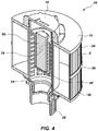
FIG. 4 ; is a cross-sectional perspective view of the filter system ofFIG. 1 -
FIG. 5 , top view of the filter ofFIG. 1 ; -
FIG. 6 is a bottom view of the filter ofFIG. 1 ; -
FIG. 7 is a top cross-sectional view of the filter ofFIG. 1 ; -
FIG. 8 is a top perspective view of the core ofFIG. 4 with the cap, the first cage, the proximal portion, the distal portion and the fitting; -
FIG. 9 is an exploded view of the core ofFIG. 8 with the cap, the first cage, a second cage, a mineral cartridge and the fitting; -
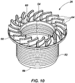
FIG. 10 is a perspective view of the fitting ofFIG. 8 ; -
FIG. 11 is a top perspective view of the core ofFIG. 8 ; -
FIG. 12 is a bottom perspective view of the core ofFIG. 8 ; -
FIG. 13 is a top view of the cage ofFIG. 8 ; -
FIG. 14 is a bottom view of the cage ofFIG. 8 ; and -
FIG. 15 is a blown-up perspective view of a proximal portion of the core ofFIG. 8 with an arm extending from the core. -
FIG. 16 is a perspective view of the cap ofFIG. 8 . -
Figures 1-4 illustrate an embodiment of afilter system 10 for utilization in a spa or pool. Thefilter system 10 may comprise afilter 12 positioned around acore 14 and acap 16 toward adistal end 18 of thecore 14. Thefilter 12 may be cylindrically shaped with achannel 20 passing through the body of the cylinder. Thechannel 20 may be centrally positioned within thefilter 12 and may allow for the core 14 to slidable engage thefilter 12 via thechannel 20. The core 14 may further include aproximal portion 22 and afirst cage 24 positioned between thedistal end 18 and theproximal portion 22. - The
filter system 10 may include a safety bulkhead fitting 26 configured to engage a spa, specifically within, or at the end, the suction line. The safety bulkhead fitting, or fitting 26, engages the core 14 opposite the suction line facing side. The fitting 26, may be placed into the spa suction line prior to engaging the core 14 or the fitting 26 may be attached to the suction line with the core 14 previously fixed to the fitting 26. Thefilter 12 may be slidably fit to thecore 14 prior to the core 14 being secured to the fitting 26; however, thefilter 12 may also be secured after thecore 14 is secured to the fitting 26. - The
filter system 10 may be considered hollow, or rather the system may allow for water to freely pass through thefilter system 10 as thefilter system 10 is secured to the spa. Water may flow freely through thefilter 12, removing the water of contaminants. The water, after passing through thefilter 12 then enters thechannel 20 of thefilter 12. Water may then flow freely from the channel into thecore 14 and passes through the center of the core 14 through the fitting 26 and into the suction line of the spa. - Referring to
Figures 5-7 , thefilter 12 is shown with thechannel 20 passing through the center. Thefilter 12 may include a rigid cylindrical filter core within thechannel 20 comprised of polymer or other rigid material to help thefilter 12 maintain its shape from a vertical perspective. Alternatively, the channel may include other structural elements such as rods or other minimal support. The structural elements, whether the rods or filter core or other support element(s) may prevent thefilter 12 from any type of collapse or sag. On the other hand, however, no structural elements may be used outside of the filter media or material itself, thus allowing collapse or deformation of thefilter 12 if the load on the pump of the spa is too great thus allowing a self-regulated bypass of water pass the filter (because it has been deformed or collapsed). The collapse of thefilter 12 may occur but ideally no more than 2.54 centimeters (one (1) inch) of collapse will be allowed. The collapse of the filter may occur by thefilter 12 twisting its shape. Total collapse may be prevented because of the interaction between a rib 66 (further described herein) and at least one cutout 38 (further described herein). The collapse may be intentional and may include a sensor recognizing the collapse of the filter in turn sending a signal to the spa owner (via a light, a message to user/owner of the spa via text or email) notifying the user of the need to change the filter. Alternatively, a visual indicator may also be used, at the top of thefilter 12, wherein if a gap is observed toward the top of thefilter 12 marks may be shown to indicate replacement of the filter is needed. Different methods of visual indication may include color such, such as green, yellow and red rings becoming exposed. Likewise other visual rings with easy to read words, such as "order replacement" and "replace now" and other variations on that theme, easily read by a user that notify of need for filter replacement. - The
filter 12 may include atop filter plate 28 and abottom filter plate 30. Thefilter plates filter system 10 as a whole. Thefilter plates filter material 8 in a more rigid position. Thefilter plates perimeter 32 of thefilter 12. Thefilter plates lips 34 that extend, at least partially, toward the opposite filter plate. Aring 36, which may be flexible, may also extend around a central portion of thefilter 12 adjacent and in contact with thefilter material 8. Thering 36 may maintain thefilter material 8 in a desired position as well as provide stability and rigidity to thefilter 12 itself. Thering 36 may be comprised of the same material as the filter media or it may be any other flexible material that aids in maintaining shape and rigidity of thefilter 12, which may include nylon, plastics, fabrics or metals. - The
filter 12 may also include at least one cut out 38, or void in both thetop filter plate 28 and thebottom filter plate 30. The at least onecutout 38 may be aligned in both thetop filter plate 28 and thebottom filter plate 30. Thecutout 38 may extend through bothfilter plates cutout 38 may be aligned through the entire cylindrical longitudinal body. - A standard filter may comprise standard filter media, or filter material which may comprise the same density of filter material circumferentially around the cylindrical filter. Referring to
Figure 7 , thefilter material 8 comprises multiple or a plurality of peaks and valleys as is standard for a spa filter. However, thefilter material 8 may be denser with one portion of thefilter material 8 over the other material, for example, thefilter material 8 on one half of the cylinder may be denser than on the other half of the cylinder of thefilter 12. The at least onecutout 38 of the filter allows for a single orientation of thefilter 12 such that the denser side of thefilter 12 may face the center of a spa and the less dense side of thefilter material 8 of thefilter 12 may face the wall of the spa. Thus a more efficient flow may be accomplished by placing the denser portion of thefilter media 8 into the direct path of the flow to help push some of that flow towards the back of thefilter 12 where the media is less dense. - The
filter material 8 is easily manipulatable to allow an element to pass through the at least one cut out 38 with the element also running through a valley of thefilter material 8. The at least one cut out 38 may be configured to receive a portion of thecore 14 for proper orientation of thefilter 12 with thecore 14. Such that the filter may be oriented the same direction each time thefilter 12 is installed, or reinstalled. - The top and
bottom filter plates -
Figures 8 and9 illustrate the core 14 with thefirst cage 24 with theproximal portion 22 and thedistal end 18. Theproximal portion 18 may include ashoulder 40 extending circumferentially away from a center of the core and toward the base of thefirst cage 24. Theshoulder 40 may be configured to receive thefilter 12 and allow it to rest on theshoulder 40. Extending proximal theshoulder 40 is a core threadedportion 42 that may include threads configured to engage the fitting 26. Thecap 16 may engage the core 14 at thedistal end 18 and may be threaded to thecore 14. The core 14 may further include asecond cage 44 which may be positioned within thefirst cage 24. Thesecond cage 44 may be welded to thefirst cage 24 creating a single element which is permanently fixed. Alternatively, thesecond cage 44 may be a separate element configured to engage thefirst cage 24 through a threaded fit, snap fit, press fit or other fit which may be reversibly attached. - The
second cage 44 which may reside adjacent to thedistal end 18 or engage thedistal end 18. Thesecond cage 44 may extend proximally within thefirst cage 24 and terminate at a second cageproximal end 46 at least partially within thefirst cage 24. Thesecond cage 44 may comprise anopening 47 at the second cage distal end 48 to allow for easy addition or removal or a mineral (or similar)cartridge 50. Access to the second cage opening 47 may be achieved by removing thecap 16. Thecartridge 50 may be slidably inserted into thesecond cage opening 47. Thecartridge 50 is held into place by thesecond cage 44 and thecap 16. However, it is contemplated that thecartridge 50 may be force fit into thesecond cage 44 or thesecond cage 28 may include a snapping lip that holds thecartridge 50 in thesecond cage 28 and only when the second lip is manipulated may the cartridge be removed. It will be appreciated that any number of ways to secure the cartridge in thefilter system 10, and specifically within thesecond cage 44 are contemplated and included within the scope of this embodiment. - As the water is pulled through the
filter 12 it is exposed to themineral cartridge 50. By having the second cage positioned in the upper middle of the core 14, and thus thecartridge 50 suspended, it allows water to flow in and around thecartridge 50 without restricting the overall flow and performance of the spa. This also allows easy access to the cartridge by removing thecap 16 and prevents anything from falling down into the suction line or filter line of the spa. The second cage may also allow other styles of cartridges to be used beyond a mineral cartridge; this could include but would not be limited to aroma therapy cartridges, chlorine tablets and bromine tablets. - The
first cage 24 andsecond cage 44 may comprise a lattice like structure or cage like structure that allows the free flow of water there through and there between. Thefirst cage 24 andsecond cage 44 designs comprise multiple openings and shaped such that no object could physically block enough of the openings at one time to create enough suction to hold it down. Thedistal end 18 may also engage thesystem cap 16 which may secure thefilter 12 to the core 14 preventing, at least substantial, vertical movement of thefilter 12 on thecore 14. Thesystem cap 16 may maintain thefilter system 10 engaged with the spa with the aid of other elements of thefilter system 10, such as the fitting 26. - Referring to
Figure 10 , theproximal portion 22 of the core may engage the fitting 26 that may be mounted into the spa itself or the suction line of the spa itself. The fitting 26 may includeexterior threads 52 that allow the fitting 26 to be secured to the spa. Theexterior threads 52 may be complementary with and consistent with threads that currently reside within current spas allowing a retrofit; however, the fitting 26 may also be used in all new manufacture spas as well. - The fitting 26 may comprise a
hole 54 passing centrally through the fitting allowing the passage of water into the suction line of the spa. The fitting 26 may include acage facing end 56 which engages thefirst cage 24 and aspa facing end 58 which engages the spa.Interior threads 60 may extend, at least partially, from thecage facing end 56 within thehole 54 of the fitting. Complementary threads may be positioned on an outside of afitting facing end 62 of the first cage 24 (refer toFigure 12 ). The core 14 may be rotatably advanced onto the fitting 26. The fitting 26 may further include a series offins 64, or ribs or barbs, toward thecage facing end 56. Thefins 64 may prevent removal of the fitting 26 from thecore 14. Thefins 64 may have a sloped or ramped design that when engaged with the core 14 thecore 14 may only be advanced in a single direction. Thefins 64 are of a sloped orientation (from a top orientation) wherein thefins 64 may extend tangential to the outer perimeter of the fitting 26 and may curve or bend toward thehole 54 of the fitting 26 in such a way to allow advancement of the core 14 onto the fitting 26 in a one-way direction. Alternatively, the fins may be straight and extend from the outer perimeter of the fitting to thehole 54. Further still, thefins 64 may resemble a simple ratchet system with peaks and valleys that may engage a locking arm of thecore 14. - The fitting 26 may be comprised of a polymer or polymer like material and may be PVC or other polyurethane or other hard plastic that maintains its shape and is not easily deformed. The fitting 26 may be substantially rigid to be fitted to the spa, or suction line, and strong enough to receive the
core 14 and essentially the remainder of thefilter system 10. It will be appreciated that any number of materials are contemplated including all plastics and polymers as well as metals and carbon-fiber alternatives. - Referring to
Figures 11-15 , thefirst cage 24 may comprise a longitudinal tube. Arib 66 may extend away from a center line of thefirst cage 24. Therib 66 may extend longitudinally along the length of the tube terminating at theshoulder 40. Therib 66 may provide a rigid orientation feature for the filter 12 (refer toFigure 7 ) as described previously herein, wherein therib 66 may slidably engage thecutout 38 and thefilter 12 such that thefilter 12 is non-rotatable when engaged to thecore 14. - The
first cage 24 also includes anarm 68, which may be a locking arm. Thearm 68 may ratchet into place allowing thefins 64 of the fitting 26 to push thearm 68 up and out of the way as thefirst cage 24 is advanced onto the fitting 26 in a single direction. The arm may have a ramp or sloped design that allows it to be displaced as thefirst cage 24 is advanced onto the fitting 26. Thearm 68 prevents the reversal of thefirst cage 24 off of the fitting, and specifically any inadvertent back out, or removal by creating a hard stop, by thearms 68 engaging or pressing against thefins 64. - The
arm 68 may be flexible such that the arm may be manually or physically manipulated, or actuated, out of a resting position to remove the hard stop against thefins 64 and allow a user to remove thefirst cage 24 from the fitting 26, but only so long as thearm 68 is lifted out of the way of thefins 64. Thearm 68 may be pressedly pushed in an upward direction, or toward thecap 16 of thefilter system 10, to remove the stop of thearm 68 against thefins 64. Alternatively, thearm 68 may bias a number of different directions to remove the stop. After thearm 68 is physically manipulated it may automatically return to its original position. - The
arm 68 and thefins 64 may provide a safety feature not currently found in current designs. While thecore 14 is in place that a user may have little risk to life or injury when replacing thefilter 12 even if the spa pump is on. The purpose is for the core 14 to remain in place while thefilter 12 is removed and cleaned and then replaced or a new filter is placed over thecore 14. Water may flow freely through the core 14 while preventing objects from entering thefirst cage 24 and thus the suction line and pump which may cause harm to the pump. Additionally thefirst cage 24 prevents the suction line from being clogged or the pump from burning out because it will be difficult to cover enough of the openings of the cage or lattice design to prevent all the water from passing through. - The core 14 including the
first cage 24 and thesecond cage 28 may be comprised of a rigid plastic such as PVC or other polymer. The core 14 may be required to be substantially rigid and will require a firm plastic, metal or carbon-fiber to maintain its position and shape while withstanding the forces of the suction pump of the spa. - Referring to
Figures 13 -15 , thearm 68 may extend outward from a center of thecore 14. Thearm 68 may cut into theshoulder 40 such that thearm 68 may be flexible allowing it to be easily moved when advancing the core 14 onto the fitting 26. Theramp 70 of the arm may extend from the downward facing portion of thearm 68 such that it may engage thefins 64. - The
arm 68 with the core 14 may be manufactured in a single piece, or injection mold, the same material as the remainder of the core 14 only thinner to allow it to be manipulated; however, the arm may be an alternative material that is welded or attached to the core in the same or similar manner as though it was one composite piece. - Referring to
Figure 16 , thefilter system cap 16 includesridges 72 that may provide ease in attaching or removing thefilter system cap 16 to thefilter system 10. Theridges 72 may includecomplementary grooves 74 that may receive a user's fingers or digits. Thefilter system cap 16 may include acavity 76 passing at least partially through the body of thefilter system cap 16. Thecavity 76 may include threads that may complementary thread with thedistal end 22 of thecore 14. Acore facing portion 78 of thefilter system cap 16 may be larger in diameter than the body of thefilter system cap 16 thus providing a larger footprint to engage thefilter 12 preventing thefilter 12 from undesired vertical motion. Thecore facing portion 78 may sit against thefilter 12 when thecap 16 is in place on thecore 14. - While the current
filter system cap 16 design may include specifics with regard to ridges, grooves and larger diameters, it will be appreciated that a number of similar caps are contemplated with and without ridges and grooves, with more grooves or less grooves. Alternate cross-sectional shapes are contemplated beyond a cylinder and any cross-sectional polygonal shape may be utilized. Additionally, wings which may protrude from thecore facing portion 78 to secure thefilter 12 to the core 14 are also contemplated. Furthermore, depth of thecavity 76 and displacement of the threads is variable so long as the cap is sufficiently attached and secured to thecore 14. The cap may not require threads and may be a locking fit, snap fit, press fit or other means to maintain thecap 16 on thecore 14. - The
cap 16 may be comprised of a polymer or polymer like material and may be PVC or other polyurethane or other hard plastic that maintains its shape and is not easily deformed, similar to the fitting 26. Thecap 16 may be substantially rigid to secure theentire filter system 10 into place within or on the spa. It will be appreciated that any number of materials are contemplated including all plastics and polymers as well as metals and carbon-fiber alternatives. - One method of assembly for the
filter system 10 may include positioning the fitting 26 into the spa or the suction line of the spa. Advancing the core 14 into or onto the fitting 26 to the proper filter orientation. Placing or positioning thesecond cage 28 onto or into thefirst cage 24 if thesecond cage 28 is a separate element. Placing thefilter 12 onto the core 14 in the orientation allowed by thecutout 38 and theorientation rib 66. Advancing thecap 16 onto thecore 14 and securing theentire filter system 10 into place. - A filter system as described herein may, at least partially, be assembled by one of the following methods:
- A method of assembling a filter system to a spa may comprise: securing a fitting to a suction line of a spa, wherein the fitting comprises a central hole to allow water to pass there through; engaging a core to the fitting by advancing the core in a one-way direction, wherein the core comprises: a tubular body and an arm extending laterally from the tubular body, the arm is configured to engage the fitting to allow one-way advancement of the core; and a rib extending from the tubular body and at least partially the length of the core.
- The method may also comprise: positioning a filter around the core in a single orientation wherein the filter comprises: at least one cutout configured to receive the rib to orient the filter in a single position.
- The method may also comprise: locking a cap onto a distal portion of the core wherein the cap secures a filter to the core.
- The method may also include the fitting wherein the fitting further comprises a plurality of fins facing a core.
- Another method of replacing a filter system may comprise: removing a filter from a spa; securing a fitting to the spa, wherein the fitting comprises a central hole to allow water to pass there through; and engaging a core to the fitting by advancing the core onto the fitting.
- The method may further comprise: engaging the arm to the fitting to allow one-way advancement of the core, wherein the fitting further comprises a plurality of fins facing the core wherein the arm is configured to interfere with the plurality of fins.
- The method may even further comprise: locking the core to the fitting, wherein the core comprises: a tubular body and an arm extending laterally from the tubular body; wherein the fitting comprises a plurality of fins configured to engage the arm of the core preventing withdrawal of the core.
- The method may further comprise: positioning a filter around the core in a single orientation wherein the filter comprises: at least one cutout configured to receive a rib of the core, wherein the rib and the cutout orient the filter in a single position.
- The method may further comprise: locking a cap onto a distal portion of the core wherein the cap secures the filter to the core.
- A method of removing a filter system may comprise: removing a cap from a core; removing a filter from the core; and actuating an arm of the core to disengage a fitting.
- The method may further comprise: removing the core from the fitting, wherein the fitting comprises a plurality of fins which engage the arm allowing one-way advancement of the core onto the fitting.
- Although the foregoing disclosure provides many specifics, such as use of the system in spas, it will be appreciated that pools, bathtubs, and other filterable water holding devices are contemplated and these should not be construed as limiting the scope of any of the ensuing claims. Other embodiments may be devised which do not depart from the scopes of the claims.
Claims (10)
- A filter system comprising a safety bulkhead fitting (26), a cap (16), a filter (12), a core (14), and a first cage (24), characterised in that:the safety bulkhead fitting (26) including a cage-facing end (56) for engaging the core (14) at a proximal portion (22) of the core (14) and a spa-facing end (58) for engaging a suction line of a spa;the cap (16) for engaging the core (14) at a core distal portion (18) and reversibly securing the filter (12) to the core (14);the filter (12) with a channel (20) passing therethrough, the core (14) slidably engageable in the channel (20), wherein water may flow freely through the filter (12), and after passing through the filter (12) may enter the channel (20) of the filter (12) and then may flow freely from the channel (20) into the core (14) through the safety bulkhead fitting (26) and into the suction line of the spa; andthe core (14) comprising:a proximal portion (22) for engaging the safety bulkhead fitting (26) and the core distal portion (18) with the first cage (24) positioned between the proximal portion (22) and the core distal portion (18), the first cage (24) comprising a lattice-like structure that allows the free flow of water therethrough;a second cage (44) positionable within the first cage (24) towards the core distal portion (18), the second cage (44) comprising a lattice-like structure that allows the free flow of water therethrough, the second cage (44) configured to receive a cartridge, the second cage (44) comprising an opening (47) at the second cage distal end (48) to allow for easy addition and/or removal of cartridge (50), the second cage opening accessed by removing the cap (16);the cartridge (50) being selected from one of a mineral cartridge, chlorine tablets, bromine tablets, and aroma therapy cartridges;wherein as water is pulled through the core (14) it is exposed to the cartridge (50), and wherein the cartridge (50) may be accessed by removing the cap (16); anda shoulder (40) positioned toward the proximal portion (22), the shoulder extending circumferentially from the core for the filter (12) to abut the shoulder (40).
- The filter system of claim 1, wherein the first cage (24) comprises a tubular body with a plurality of openings and a rib (66) extending outwardly from the core away from a center line of the first cage (24) and at least partially extending a length of the first cage (24).
- The filter system of claim 1 or 2, the core (14) further comprising an arm (68) extending from the shoulder (40), the arm (68) configured to engage a plurality of fins (64) of the fitting (26) such that the core (14) may be advanced onto the safety bulkhead fitting (26) in a one-way direction.
- The filter system of claims 1-3, wherein the arm (68) is sloped and deformable.
- The filter system of claims 2-4 wherein the filter (12) comprises:
a top plate (28) and a bottom plate (30) wherein each of the top plate (28) and the bottom plate (30) comprise a cutout (38) at least partially extending from the channel (20) toward an outer perimeter of the filter (12), the rib (66) of the first cage (24) receivable in the cutout (38). - The filter system of claims 1, 2 or 4, wherein the filter (12) further comprises a structural member within the channel to maintain rigidity of the filter (12).
- The filter system of claims 1, 2, 4 or 6 wherein the filter (12) is configured to fit around the core (14), wherein a cutout of the filter (12) is configured to receive a rib of the core (14) orienting the filter (12) in a first position.
- The filter system of claims 1, 2, 4, 6 or 7, wherein the filter (12) comprises filter media wherein the filter media (8) is denser toward one side of the filter (12) and less dense toward an opposite side of the filter (12).
- The filter system of claims 1, 2, 4, or 6-8, the safety bulkhead fitting (26) further comprising:a hole (54) passing through a center thereof; anda plurality of fins (64) configured to engage an arm (68) of the core (14) wherein the fins (64) allow one-way advancement of the core (14) onto the safety bulkhead fitting (26).
- The filter system of claims 1, 2, 4, or 6-9, wherein the filter (12) is removable from the core (14) without removing the core (14) from the safety bulkhead fitting (26).
Applications Claiming Priority (2)
| Application Number | Priority Date | Filing Date | Title |
|---|---|---|---|
| US15/361,892 US10518202B2 (en) | 2016-11-28 | 2016-11-28 | Filter system |
| PCT/US2016/068325 WO2018097848A1 (en) | 2016-11-28 | 2016-12-22 | Filter system |
Publications (3)
| Publication Number | Publication Date |
|---|---|
| EP3544712A1 EP3544712A1 (en) | 2019-10-02 |
| EP3544712A4 EP3544712A4 (en) | 2020-06-24 |
| EP3544712B1 true EP3544712B1 (en) | 2022-09-07 |
Family
ID=62193423
Family Applications (1)
| Application Number | Title | Priority Date | Filing Date |
|---|---|---|---|
| EP16922512.5A Active EP3544712B1 (en) | 2016-11-28 | 2016-12-22 | Filter system |
Country Status (10)
| Country | Link |
|---|---|
| US (2) | US10518202B2 (en) |
| EP (1) | EP3544712B1 (en) |
| AU (2) | AU2016430233B2 (en) |
| CA (1) | CA3044399C (en) |
| DK (1) | DK3544712T3 (en) |
| ES (1) | ES2929859T3 (en) |
| NZ (2) | NZ762316A (en) |
| PL (1) | PL3544712T3 (en) |
| PT (1) | PT3544712T (en) |
| WO (1) | WO2018097848A1 (en) |
Families Citing this family (11)
| Publication number | Priority date | Publication date | Assignee | Title |
|---|---|---|---|---|
| US10518202B2 (en) | 2016-11-28 | 2019-12-31 | Bullfrog International, L.C. | Filter system |
| CN112240110A (en) * | 2019-07-19 | 2021-01-19 | 上海荣威塑胶工业有限公司 | Water circulation system for water pool and water pool |
| US11008770B1 (en) | 2020-01-17 | 2021-05-18 | Saratoga Spa & Bath, Inc. | Reconfigurable spa filter treatment systems and methods for treating filtered water for spas and hot tubs |
| US11825974B1 (en) * | 2020-03-01 | 2023-11-28 | Michael O. Murphy | Expandable strainer insert for bottles |
| US11560917B1 (en) * | 2020-03-05 | 2023-01-24 | Latham Pool Products, Inc. | Mounting arrangements for pool fittings and methods for mounting pool fittings |
| EP4527482B1 (en) * | 2020-03-21 | 2026-05-13 | Wuhu Midea Kitchen and Bath Appliances Mfg. Co., Ltd. | Filter element assembly, filter, water path control system, and water heater |
| USD980385S1 (en) * | 2021-11-03 | 2023-03-07 | Shilin Huang | Water filter |
| US12311293B2 (en) | 2022-02-10 | 2025-05-27 | Mann+Hummel Gmbh | Filter head assembly having a threaded bayonet connector adapter with a position tolerance improving retainer ring |
| USD1118822S1 (en) * | 2023-06-08 | 2026-03-17 | Sundance Spas, Inc. | Filter assembly |
| USD1052688S1 (en) * | 2023-06-19 | 2024-11-26 | Shilin Huang | Water filter |
| USD1052044S1 (en) * | 2023-08-14 | 2024-11-19 | Shilin Huang | Water filter |
Citations (3)
| Publication number | Priority date | Publication date | Assignee | Title |
|---|---|---|---|---|
| US6217754B1 (en) * | 1998-10-08 | 2001-04-17 | Aplister, S.A. | Swimming pool filter |
| US6325926B1 (en) * | 1999-11-18 | 2001-12-04 | Austin Hansen | Liquid treatment apparatus |
| US20120074052A1 (en) * | 2010-09-23 | 2012-03-29 | John Brandreth | Chemical dispenser |
Family Cites Families (22)
| Publication number | Priority date | Publication date | Assignee | Title |
|---|---|---|---|---|
| US3467256A (en) * | 1967-07-18 | 1969-09-16 | Wix Corp | Multi-density screw-on throw away type filter |
| GB8407220D0 (en) * | 1984-03-20 | 1984-04-26 | Fram Ind Uk Ltd | Assemblies of screw-thread conjoined parts |
| US4683057A (en) * | 1985-03-08 | 1987-07-28 | Henry Valve Company | Refillable filter-drier assembly |
| US4921600A (en) * | 1986-03-12 | 1990-05-01 | Meissner Mfg. Co., Inc. | Filter cartridge for swimming pools and spas |
| US5211846A (en) * | 1990-07-30 | 1993-05-18 | Pleatco Electronic & Filter Corp. | Replacement filter cartridge assembly |
| US5109651A (en) * | 1990-10-05 | 1992-05-05 | Packaged Ice, Inc. | Ice bagger |
| US5190651A (en) | 1991-06-24 | 1993-03-02 | Sta-Rite Industries, Inc. | Filter cartridge |
| US5250179A (en) | 1992-03-27 | 1993-10-05 | Porous Media Corporation | Compactable filter and compactable filter mounting means |
| CN1067291C (en) * | 1992-11-06 | 2001-06-20 | 帕尔公司 | Filter |
| US5409606A (en) * | 1993-05-04 | 1995-04-25 | Sta-Rite Industries, Inc. | Filter apparatus |
| AU3968495A (en) * | 1994-10-21 | 1996-05-15 | Pall Corporation | Fluid processing apparatus |
| US5779913B1 (en) | 1996-08-01 | 2000-02-01 | Fountainhead Technologies Inc | Water purifier for a spa |
| US6739459B1 (en) | 1998-06-26 | 2004-05-25 | Pall Corporation | Filter element including bonded end caps and support core |
| US6217763B1 (en) * | 1999-08-11 | 2001-04-17 | Usf Filtration And Separation Group, Inc. | Back-flushable filter cartridge assemblies |
| US6751814B2 (en) | 2001-11-02 | 2004-06-22 | Roy Mattson | Whirlpool bath filter and suction device |
| US7416663B2 (en) * | 2006-04-14 | 2008-08-26 | Pleatco Electronic & Filter Corporation | Replacement filter cartridge assembly having an internal lock ring |
| US20070241045A1 (en) * | 2006-04-17 | 2007-10-18 | Kott Leonard B | Replaceable tandem filter cartridge assembly |
| CN101472654B (en) * | 2006-06-20 | 2015-06-10 | 卡明斯过滤Ip有限公司 | Replaceable filter element containing multiple filter qualities and related filter system, process and method |
| US8034240B2 (en) * | 2009-03-02 | 2011-10-11 | Parker-Hannifin Corporation | Coalescing element |
| US9764263B2 (en) * | 2012-03-01 | 2017-09-19 | Caterpillar Inc. | Filter element |
| US20140102966A1 (en) * | 2012-10-12 | 2014-04-17 | Lmi Roto, Llc | Spa Filter Bypass |
| US10518202B2 (en) | 2016-11-28 | 2019-12-31 | Bullfrog International, L.C. | Filter system |
-
2016
- 2016-11-28 US US15/361,892 patent/US10518202B2/en active Active
- 2016-12-22 CA CA3044399A patent/CA3044399C/en active Active
- 2016-12-22 PL PL16922512.5T patent/PL3544712T3/en unknown
- 2016-12-22 AU AU2016430233A patent/AU2016430233B2/en active Active
- 2016-12-22 NZ NZ762316A patent/NZ762316A/en not_active IP Right Cessation
- 2016-12-22 NZ NZ753721A patent/NZ753721A/en not_active IP Right Cessation
- 2016-12-22 PT PT169225125T patent/PT3544712T/en unknown
- 2016-12-22 ES ES16922512T patent/ES2929859T3/en active Active
- 2016-12-22 WO PCT/US2016/068325 patent/WO2018097848A1/en not_active Ceased
- 2016-12-22 EP EP16922512.5A patent/EP3544712B1/en active Active
- 2016-12-22 DK DK16922512.5T patent/DK3544712T3/en active
-
2019
- 2019-03-25 US US16/363,524 patent/US11179660B2/en active Active
-
2020
- 2020-02-04 AU AU2020200793A patent/AU2020200793B2/en active Active
Patent Citations (3)
| Publication number | Priority date | Publication date | Assignee | Title |
|---|---|---|---|---|
| US6217754B1 (en) * | 1998-10-08 | 2001-04-17 | Aplister, S.A. | Swimming pool filter |
| US6325926B1 (en) * | 1999-11-18 | 2001-12-04 | Austin Hansen | Liquid treatment apparatus |
| US20120074052A1 (en) * | 2010-09-23 | 2012-03-29 | John Brandreth | Chemical dispenser |
Also Published As
| Publication number | Publication date |
|---|---|
| US11179660B2 (en) | 2021-11-23 |
| AU2020200793A1 (en) | 2020-02-20 |
| PT3544712T (en) | 2022-11-09 |
| EP3544712A4 (en) | 2020-06-24 |
| US20190217230A1 (en) | 2019-07-18 |
| EP3544712A1 (en) | 2019-10-02 |
| ES2929859T3 (en) | 2022-12-02 |
| AU2020200793B2 (en) | 2021-10-21 |
| PL3544712T3 (en) | 2023-03-20 |
| DK3544712T3 (en) | 2022-11-14 |
| NZ762316A (en) | 2022-01-28 |
| US10518202B2 (en) | 2019-12-31 |
| AU2016430233A1 (en) | 2019-06-06 |
| NZ753721A (en) | 2020-03-27 |
| WO2018097848A1 (en) | 2018-05-31 |
| CA3044399C (en) | 2023-09-19 |
| CA3044399A1 (en) | 2018-05-31 |
| US20180147510A1 (en) | 2018-05-31 |
| AU2016430233B2 (en) | 2019-11-07 |
Similar Documents
| Publication | Publication Date | Title |
|---|---|---|
| AU2020200793B2 (en) | Filter system | |
| ES2210159T3 (en) | EXTENSION AND LOCK ASSEMBLY FOR ANTIGOTE FILTER ELEMENT AND CONTAINER FOR THE SAME. | |
| US6217754B1 (en) | Swimming pool filter | |
| US9528252B2 (en) | Debris trap for a drain | |
| US6687923B2 (en) | Vacuum release valve and method | |
| AU2019231879B2 (en) | Fuel filter with coalescer | |
| KR101200688B1 (en) | Inline strainer | |
| CN104902976B (en) | Can backwashing fluid processing equipment and the external member for filtered fluid | |
| US6338797B1 (en) | Filter device for wastewater treatment system | |
| CA2430169A1 (en) | Non-electric sanitation water vessel system | |
| ES3014715T3 (en) | Filter arrangement including prefiltration filter element and filter device | |
| CA1321553C (en) | Personal, portable, disposable tap water filter | |
| JP2006116541A (en) | Fluid filter having module type housing and its manufacturing method | |
| US20070187306A1 (en) | Filter housing and parts therefor | |
| US6627078B1 (en) | Filter element cover grip | |
| CA2954669C (en) | Gas-evacuating filter | |
| ES2332148T3 (en) | FILTRATION DEVICE. | |
| US20090084722A1 (en) | Core adapter | |
| KR200444043Y1 (en) | Eye drop case | |
| US20110094386A1 (en) | Marine Water Separating Fuel Filter | |
| EP2542130B1 (en) | A device for disabling flow shut-off selector members for percolating filter systems and a kit including said device | |
| KR200431991Y1 (en) | Portable drinking water conversion container | |
| KR20110079963A (en) | Filter assembly | |
| IT202200002842U1 (en) | IMPROVED AERATOR FILTER FOR WATER DISPENSER | |
| AU752250B2 (en) | Vacuum release valve and method |
Legal Events
| Date | Code | Title | Description |
|---|---|---|---|
| STAA | Information on the status of an ep patent application or granted ep patent |
Free format text: STATUS: THE INTERNATIONAL PUBLICATION HAS BEEN MADE |
|
| PUAI | Public reference made under article 153(3) epc to a published international application that has entered the european phase |
Free format text: ORIGINAL CODE: 0009012 |
|
| STAA | Information on the status of an ep patent application or granted ep patent |
Free format text: STATUS: REQUEST FOR EXAMINATION WAS MADE |
|
| 17P | Request for examination filed |
Effective date: 20190521 |
|
| AK | Designated contracting states |
Kind code of ref document: A1 Designated state(s): AL AT BE BG CH CY CZ DE DK EE ES FI FR GB GR HR HU IE IS IT LI LT LU LV MC MK MT NL NO PL PT RO RS SE SI SK SM TR |
|
| AX | Request for extension of the european patent |
Extension state: BA ME |
|
| DAV | Request for validation of the european patent (deleted) | ||
| DAX | Request for extension of the european patent (deleted) | ||
| A4 | Supplementary search report drawn up and despatched |
Effective date: 20200528 |
|
| RIC1 | Information provided on ipc code assigned before grant |
Ipc: B01D 29/11 20060101ALI20200520BHEP Ipc: B01J 8/00 20060101ALI20200520BHEP Ipc: B01D 29/05 20060101ALI20200520BHEP Ipc: B01D 24/40 20060101AFI20200520BHEP Ipc: B01D 29/03 20060101ALI20200520BHEP Ipc: B01D 37/00 20060101ALI20200520BHEP |
|
| STAA | Information on the status of an ep patent application or granted ep patent |
Free format text: STATUS: EXAMINATION IS IN PROGRESS |
|
| 17Q | First examination report despatched |
Effective date: 20201222 |
|
| GRAP | Despatch of communication of intention to grant a patent |
Free format text: ORIGINAL CODE: EPIDOSNIGR1 |
|
| STAA | Information on the status of an ep patent application or granted ep patent |
Free format text: STATUS: GRANT OF PATENT IS INTENDED |
|
| INTG | Intention to grant announced |
Effective date: 20220322 |
|
| GRAS | Grant fee paid |
Free format text: ORIGINAL CODE: EPIDOSNIGR3 |
|
| GRAA | (expected) grant |
Free format text: ORIGINAL CODE: 0009210 |
|
| STAA | Information on the status of an ep patent application or granted ep patent |
Free format text: STATUS: THE PATENT HAS BEEN GRANTED |
|
| AK | Designated contracting states |
Kind code of ref document: B1 Designated state(s): AL AT BE BG CH CY CZ DE DK EE ES FI FR GB GR HR HU IE IS IT LI LT LU LV MC MK MT NL NO PL PT RO RS SE SI SK SM TR |
|
| REG | Reference to a national code |
Ref country code: GB Ref legal event code: FG4D |
|
| REG | Reference to a national code |
Ref country code: CH Ref legal event code: EP Ref country code: AT Ref legal event code: REF Ref document number: 1516559 Country of ref document: AT Kind code of ref document: T Effective date: 20220915 |
|
| REG | Reference to a national code |
Ref country code: IE Ref legal event code: FG4D |
|
| REG | Reference to a national code |
Ref country code: DE Ref legal event code: R096 Ref document number: 602016074933 Country of ref document: DE |
|
| REG | Reference to a national code |
Ref country code: PT Ref legal event code: SC4A Ref document number: 3544712 Country of ref document: PT Date of ref document: 20221109 Kind code of ref document: T Free format text: AVAILABILITY OF NATIONAL TRANSLATION Effective date: 20221104 |
|
| REG | Reference to a national code |
Ref country code: DK Ref legal event code: T3 Effective date: 20221110 |
|
| REG | Reference to a national code |
Ref country code: ES Ref legal event code: FG2A Ref document number: 2929859 Country of ref document: ES Kind code of ref document: T3 Effective date: 20221202 |
|
| REG | Reference to a national code |
Ref country code: NL Ref legal event code: FP |
|
| REG | Reference to a national code |
Ref country code: DE Ref legal event code: R081 Ref document number: 602016074933 Country of ref document: DE Owner name: BULLFROG INTERNATIONAL, L.C., HERRIMAN, US Free format text: FORMER OWNER: BULLFROG INTERNATIONAL, L.C., BLUFFDALE, UT, US |
|
| REG | Reference to a national code |
Ref country code: LT Ref legal event code: MG9D |
|
| RAP4 | Party data changed (patent owner data changed or rights of a patent transferred) |
Owner name: BULLFROG INTERNATIONAL, L.C. |
|
| REG | Reference to a national code |
Ref country code: NO Ref legal event code: T2 Effective date: 20220907 |
|
| PG25 | Lapsed in a contracting state [announced via postgrant information from national office to epo] |
Ref country code: SE Free format text: LAPSE BECAUSE OF FAILURE TO SUBMIT A TRANSLATION OF THE DESCRIPTION OR TO PAY THE FEE WITHIN THE PRESCRIBED TIME-LIMIT Effective date: 20220907 Ref country code: RS Free format text: LAPSE BECAUSE OF FAILURE TO SUBMIT A TRANSLATION OF THE DESCRIPTION OR TO PAY THE FEE WITHIN THE PRESCRIBED TIME-LIMIT Effective date: 20220907 Ref country code: LV Free format text: LAPSE BECAUSE OF FAILURE TO SUBMIT A TRANSLATION OF THE DESCRIPTION OR TO PAY THE FEE WITHIN THE PRESCRIBED TIME-LIMIT Effective date: 20220907 Ref country code: LT Free format text: LAPSE BECAUSE OF FAILURE TO SUBMIT A TRANSLATION OF THE DESCRIPTION OR TO PAY THE FEE WITHIN THE PRESCRIBED TIME-LIMIT Effective date: 20220907 Ref country code: FI Free format text: LAPSE BECAUSE OF FAILURE TO SUBMIT A TRANSLATION OF THE DESCRIPTION OR TO PAY THE FEE WITHIN THE PRESCRIBED TIME-LIMIT Effective date: 20220907 |
|
| PG25 | Lapsed in a contracting state [announced via postgrant information from national office to epo] |
Ref country code: HR Free format text: LAPSE BECAUSE OF FAILURE TO SUBMIT A TRANSLATION OF THE DESCRIPTION OR TO PAY THE FEE WITHIN THE PRESCRIBED TIME-LIMIT Effective date: 20220907 Ref country code: GR Free format text: LAPSE BECAUSE OF FAILURE TO SUBMIT A TRANSLATION OF THE DESCRIPTION OR TO PAY THE FEE WITHIN THE PRESCRIBED TIME-LIMIT Effective date: 20221208 |
|
| PG25 | Lapsed in a contracting state [announced via postgrant information from national office to epo] |
Ref country code: SM Free format text: LAPSE BECAUSE OF FAILURE TO SUBMIT A TRANSLATION OF THE DESCRIPTION OR TO PAY THE FEE WITHIN THE PRESCRIBED TIME-LIMIT Effective date: 20220907 Ref country code: RO Free format text: LAPSE BECAUSE OF FAILURE TO SUBMIT A TRANSLATION OF THE DESCRIPTION OR TO PAY THE FEE WITHIN THE PRESCRIBED TIME-LIMIT Effective date: 20220907 Ref country code: CZ Free format text: LAPSE BECAUSE OF FAILURE TO SUBMIT A TRANSLATION OF THE DESCRIPTION OR TO PAY THE FEE WITHIN THE PRESCRIBED TIME-LIMIT Effective date: 20220907 |
|
| PG25 | Lapsed in a contracting state [announced via postgrant information from national office to epo] |
Ref country code: SK Free format text: LAPSE BECAUSE OF FAILURE TO SUBMIT A TRANSLATION OF THE DESCRIPTION OR TO PAY THE FEE WITHIN THE PRESCRIBED TIME-LIMIT Effective date: 20220907 Ref country code: IS Free format text: LAPSE BECAUSE OF FAILURE TO SUBMIT A TRANSLATION OF THE DESCRIPTION OR TO PAY THE FEE WITHIN THE PRESCRIBED TIME-LIMIT Effective date: 20230107 Ref country code: EE Free format text: LAPSE BECAUSE OF FAILURE TO SUBMIT A TRANSLATION OF THE DESCRIPTION OR TO PAY THE FEE WITHIN THE PRESCRIBED TIME-LIMIT Effective date: 20220907 |
|
| REG | Reference to a national code |
Ref country code: DE Ref legal event code: R097 Ref document number: 602016074933 Country of ref document: DE |
|
| PG25 | Lapsed in a contracting state [announced via postgrant information from national office to epo] |
Ref country code: AL Free format text: LAPSE BECAUSE OF FAILURE TO SUBMIT A TRANSLATION OF THE DESCRIPTION OR TO PAY THE FEE WITHIN THE PRESCRIBED TIME-LIMIT Effective date: 20220907 |
|
| P01 | Opt-out of the competence of the unified patent court (upc) registered |
Effective date: 20230601 |
|
| PLBE | No opposition filed within time limit |
Free format text: ORIGINAL CODE: 0009261 |
|
| STAA | Information on the status of an ep patent application or granted ep patent |
Free format text: STATUS: NO OPPOSITION FILED WITHIN TIME LIMIT |
|
| 26N | No opposition filed |
Effective date: 20230608 |
|
| PG25 | Lapsed in a contracting state [announced via postgrant information from national office to epo] |
Ref country code: SI Free format text: LAPSE BECAUSE OF FAILURE TO SUBMIT A TRANSLATION OF THE DESCRIPTION OR TO PAY THE FEE WITHIN THE PRESCRIBED TIME-LIMIT Effective date: 20220907 |
|
| REG | Reference to a national code |
Ref country code: AT Ref legal event code: UEP Ref document number: 1516559 Country of ref document: AT Kind code of ref document: T Effective date: 20220907 |
|
| PG25 | Lapsed in a contracting state [announced via postgrant information from national office to epo] |
Ref country code: HU Free format text: LAPSE BECAUSE OF FAILURE TO SUBMIT A TRANSLATION OF THE DESCRIPTION OR TO PAY THE FEE WITHIN THE PRESCRIBED TIME-LIMIT; INVALID AB INITIO Effective date: 20161222 |
|
| PG25 | Lapsed in a contracting state [announced via postgrant information from national office to epo] |
Ref country code: CY Free format text: LAPSE BECAUSE OF FAILURE TO SUBMIT A TRANSLATION OF THE DESCRIPTION OR TO PAY THE FEE WITHIN THE PRESCRIBED TIME-LIMIT Effective date: 20220907 |
|
| PG25 | Lapsed in a contracting state [announced via postgrant information from national office to epo] |
Ref country code: MK Free format text: LAPSE BECAUSE OF FAILURE TO SUBMIT A TRANSLATION OF THE DESCRIPTION OR TO PAY THE FEE WITHIN THE PRESCRIBED TIME-LIMIT Effective date: 20220907 Ref country code: IT Free format text: LAPSE BECAUSE OF FAILURE TO SUBMIT A TRANSLATION OF THE DESCRIPTION OR TO PAY THE FEE WITHIN THE PRESCRIBED TIME-LIMIT Effective date: 20220907 |
|
| PG25 | Lapsed in a contracting state [announced via postgrant information from national office to epo] |
Ref country code: MC Free format text: LAPSE BECAUSE OF FAILURE TO SUBMIT A TRANSLATION OF THE DESCRIPTION OR TO PAY THE FEE WITHIN THE PRESCRIBED TIME-LIMIT Effective date: 20220907 |
|
| PG25 | Lapsed in a contracting state [announced via postgrant information from national office to epo] |
Ref country code: MC Free format text: LAPSE BECAUSE OF FAILURE TO SUBMIT A TRANSLATION OF THE DESCRIPTION OR TO PAY THE FEE WITHIN THE PRESCRIBED TIME-LIMIT Effective date: 20220907 |
|
| PG25 | Lapsed in a contracting state [announced via postgrant information from national office to epo] |
Ref country code: BG Free format text: LAPSE BECAUSE OF FAILURE TO SUBMIT A TRANSLATION OF THE DESCRIPTION OR TO PAY THE FEE WITHIN THE PRESCRIBED TIME-LIMIT Effective date: 20220907 |
|
| PG25 | Lapsed in a contracting state [announced via postgrant information from national office to epo] |
Ref country code: MT Free format text: LAPSE BECAUSE OF FAILURE TO SUBMIT A TRANSLATION OF THE DESCRIPTION OR TO PAY THE FEE WITHIN THE PRESCRIBED TIME-LIMIT Effective date: 20220907 |
|
| PGFP | Annual fee paid to national office [announced via postgrant information from national office to epo] |
Ref country code: PT Payment date: 20241202 Year of fee payment: 9 |
|
| PGFP | Annual fee paid to national office [announced via postgrant information from national office to epo] |
Ref country code: NO Payment date: 20241220 Year of fee payment: 9 |
|
| PGFP | Annual fee paid to national office [announced via postgrant information from national office to epo] |
Ref country code: DK Payment date: 20241224 Year of fee payment: 9 |
|
| PGFP | Annual fee paid to national office [announced via postgrant information from national office to epo] |
Ref country code: BE Payment date: 20241219 Year of fee payment: 9 Ref country code: PL Payment date: 20241202 Year of fee payment: 9 Ref country code: NL Payment date: 20241219 Year of fee payment: 9 Ref country code: LU Payment date: 20241219 Year of fee payment: 9 |
|
| PGFP | Annual fee paid to national office [announced via postgrant information from national office to epo] |
Ref country code: GB Payment date: 20241219 Year of fee payment: 9 |
|
| PGFP | Annual fee paid to national office [announced via postgrant information from national office to epo] |
Ref country code: FR Payment date: 20241223 Year of fee payment: 9 |
|
| PGFP | Annual fee paid to national office [announced via postgrant information from national office to epo] |
Ref country code: AT Payment date: 20241220 Year of fee payment: 9 |
|
| PGFP | Annual fee paid to national office [announced via postgrant information from national office to epo] |
Ref country code: IE Payment date: 20241225 Year of fee payment: 9 |
|
| PGFP | Annual fee paid to national office [announced via postgrant information from national office to epo] |
Ref country code: DE Payment date: 20241227 Year of fee payment: 9 |
|
| PGFP | Annual fee paid to national office [announced via postgrant information from national office to epo] |
Ref country code: ES Payment date: 20250121 Year of fee payment: 9 |
|
| PGFP | Annual fee paid to national office [announced via postgrant information from national office to epo] |
Ref country code: CH Payment date: 20250122 Year of fee payment: 9 |
|
| PG25 | Lapsed in a contracting state [announced via postgrant information from national office to epo] |
Ref country code: TR Free format text: LAPSE BECAUSE OF FAILURE TO SUBMIT A TRANSLATION OF THE DESCRIPTION OR TO PAY THE FEE WITHIN THE PRESCRIBED TIME-LIMIT Effective date: 20220907 |