EP3544209A1 - System, electronic device, and test method - Google Patents
System, electronic device, and test method Download PDFInfo
- Publication number
- EP3544209A1 EP3544209A1 EP19157567.9A EP19157567A EP3544209A1 EP 3544209 A1 EP3544209 A1 EP 3544209A1 EP 19157567 A EP19157567 A EP 19157567A EP 3544209 A1 EP3544209 A1 EP 3544209A1
- Authority
- EP
- European Patent Office
- Prior art keywords
- test
- electronic device
- wireless communication
- frequency band
- instruction
- Prior art date
- Legal status (The legal status is an assumption and is not a legal conclusion. Google has not performed a legal analysis and makes no representation as to the accuracy of the status listed.)
- Granted
Links
Images











Classifications
-
- H—ELECTRICITY
- H04—ELECTRIC COMMUNICATION TECHNIQUE
- H04B—TRANSMISSION
- H04B17/00—Monitoring; Testing
- H04B17/0082—Monitoring; Testing using service channels; using auxiliary channels
- H04B17/0085—Monitoring; Testing using service channels; using auxiliary channels using test signal generators
-
- H—ELECTRICITY
- H04—ELECTRIC COMMUNICATION TECHNIQUE
- H04B—TRANSMISSION
- H04B17/00—Monitoring; Testing
- H04B17/10—Monitoring; Testing of transmitters
- H04B17/11—Monitoring; Testing of transmitters for calibration
-
- H—ELECTRICITY
- H04—ELECTRIC COMMUNICATION TECHNIQUE
- H04L—TRANSMISSION OF DIGITAL INFORMATION, e.g. TELEGRAPHIC COMMUNICATION
- H04L1/00—Arrangements for detecting or preventing errors in the information received
- H04L1/24—Testing correct operation
-
- H—ELECTRICITY
- H04—ELECTRIC COMMUNICATION TECHNIQUE
- H04W—WIRELESS COMMUNICATION NETWORKS
- H04W4/00—Services specially adapted for wireless communication networks; Facilities therefor
- H04W4/80—Services using short range communication, e.g. near-field communication [NFC], radio-frequency identification [RFID] or low energy communication
Definitions
- Embodiments described herein relate generally to a system, an electronic device, and a method that execute a wireless communication test.
- Gas meters, electricity meters, water meters, and the like having a short-range wireless communication function transmit the consumption of gas, electric power, water, and the like to servers of a gas company, electric power company, water company, and the like via communication hubs having short-range communication function and wide area communication function.
- the short-range wireless communication function of various meters (smart meters such as a gas meter and an electricity meter) and the communication hub are configured to mutually execute wireless communication in the 2.4 GHz band.
- the communication hub and the meter cannot mutually execute wireless communication in the 2.4 GHz band.
- a communication hub and a meter capable of wireless communication in a frequency band other than the 2.4 GHz band have been developed.
- a system comprises a first electronic device comprising a communication unit capable of wireless communication in a first frequency band and a communication unit capable of wireless communication in a second frequency band; a second electronic device comprising a communication unit capable of wireless communication in the first frequency band and a communication unit capable of wireless communication in the second frequency band; and a third electronic device that transmits a first instruction to at least one of the first electronic device or the second electronic device, the first instruction making the at least one of the first electronic device or the second electronic device execute a first test for determining whether the first electronic device and the second electronic device are capable of executing the wireless communication in the first frequency band or not.
- the at least one of the first electronic device or the second electronic device executes the first test and transmits a result of the first test to the third electronic device.
- FIG. 1 is a block diagram showing a situation in which a communication hub 20 subjected to a wireless communication test by a test device is connected to a network.
- Various meters such as a water meter 1, a gas meter 2, and an electricity meter 3 are installed in each house. Usage data of the water meter 1, usage data of the gas meter 2, and reading data of the electricity meter 3 are transmitted to the communication hub 20 by wireless communication.
- the communication hub 20 is provided in each house.
- the water usage data of the water meter 1, gas usage data of the gas meter 2, and reading data of the electricity meter 3 are transmitted from ZigBee (trademark) devices (not shown in FIG. 1 ) included in the respective meters to the communication hub 20. Then, the water usage data, the gas usage data of the gas meter 2, and the reading data of the electricity meter 3 are received via a ZigBee device (not shown in FIG. 1 ) provided in the communication hub 20.
- ZigBee trademark
- the gas meter 2 may be installed outdoors or underground.
- An in-home display (IHD) 4 is wirelessly connected to the communication hub 20.
- the in-home display (IHD) 4 is a display device on which the data (the water usage data of the water meter 1, the gas usage data of the gas meter 2, or the reading data of the electricity meter 3) received by the communication hub 20 is displayed.
- the reading data transmitted from the ZigBee device of the communication hub 20 is received by the ZigBee device (not shown in FIG. 1 ) provided in the IHD 4.
- a home energy management system (HEMS) 15 may be connected to the communication hub 20.
- the communication hub 20 aggregates meter data wirelessly transmitted from the respective meters, and wirelessly transmits the data to a server 61 of the electric power company, a server 62 of the water company, or a server 63 of the gas company periodically (for example, at intervals of thirty minutes) via the Internet 50.
- the meter data includes the water usage data of the water meter 1, the gas usage data of the gas meter 2, the reading data of the electricity meter 3, and the like.
- a wireless multi-hop system of IEEE 802.15.4g standard may be employed as the system of communication from the communication hub 20 to the Internet 50.
- the wireless multi-hop system transmits data to a communication hub called a gateway (not shown in FIG. 1 ) by sequentially multi-hopping of other communication hubs capable of establishing communication.
- the smart meters are connected to one smart meter (gateway) in a mesh-like network of the communication hub.
- a communication hub capable of establishing communication is selected, and a route to the gateway is determined.
- the gateway is connected to a wireless base station 40 via a cellular telephone line, for example, 2G/3G line or the like.
- the base station 40 is connected to the server 61 of the electric power company, the server 62 of the water company, and the server 63 of the gas company via a telephone company (called carrier) 60 and the Internet 50.
- the carrier 60 obtains meter data from each of the meters via the communication hub 20 and the base station 40.
- the base station 40 is built by the carrier 60.
- the carrier 60 obtains the usage data of water from the water meter 1, the usage data of gas from the gas meter 2, and the reading data from the electricity meter 3, by transmitting instructions to the meters via the communication hub 20.
- the carrier 60 controls the water meter 1, the gas meter 2, or the electricity meter 3 and stops use of electric power, water, or gas in a house that is in arrears with payment, by transmitting instructions to the meters 1, 2, or 3, in response to the request from the electric power company 61, the water company 62 or the gas company 63.
- the communication hub 20 includes plural, for example, three wireless communication devices, for example, a 2G/3G device, the ZigBee device, and an RF mesh device (a mesh network of IEEE 802.15.4g).
- the ZigBee device is configured to receive the meter data from various meters
- the 2G/3G device and the RF mesh device are configured to transmit the meter data transmitted from the various meters to the network side.
- the 2G/3G device executes communication using the cellular telephone line.
- the RF mesh device is configured to execute multi-hop communication with the meter (communication hub 20) and is mainly employed in the area where the intensity of the radio waves of a cellular telephone line is weak or in a suburb where cellular telephone line does not exist.
- the communication with the network is not limited to wireless communication but may be communication using power lines.
- the communication using the power lines are mainly used in condominiums, buildings, and the like.
- a device used for communication with the network is selected in accordance with the installation environment of the communication hub 20.
- the wireless multi-hop system is used for communication between communication hubs in a suburb where the intensity of mobile telephone line is weak or the mobile telephone line does not exist.
- the communication hub 20 in a range where radio waves of the base station 40 reach may be connected to the base station 40 via the 2G/3G cellular telephone line, directly.
- communication with the network is not limited to wireless communication, but may be communication using power lines. Communication using the power lines is mainly used in condominiums, buildings, and the like.
- the ZigBee device receives the meter data from various meters by mutually executing communication with various meters via an antenna provided in the ZigBee device.
- the RF mesh device transmits the received meter data to the gateway via an antenna by way of (by hopping) an RF mesh device of the other communication hub 20.
- the RF mesh device also forms a wireless mesh network with the other communication hub 20 via the antenna and transmits the meter data to the gateway 30.
- Examples of the communication hub 20 include a single-band device and a dual-band device.
- the single-band device includes a ZigBee device conformable to a single frequency band and mutually executes wireless communication with various meters, and the like in the single frequency band.
- the dual-band device includes a ZigBee device conformable to two frequency bands, and mutually executes wireless communication with various meters, and the like in any one of the two frequency bands in accordance with situations of the dual-band device such as the distances from various meters, and the like, the communication speed, and ambient noise.
- the single-band device includes a ZigBee device capable of executing wireless communication in the 2.4 GHz frequency band. Since 2.4 GHz radio waves have an excellent property of traveling straight and propagation of the 2.4 GHz radio waves is prevented by an obstruction such as a wall, a ZigBee device capable of executing wireless communication in sub-GHz frequency band has been proposed.
- An example of the sub-GHz frequency band may be any frequency band lower than 1 GHz band.
- the proposed ZigBee device executes wireless communication in 868 MHz frequency band. In this specification, 868 MHz is used as one example of the sub-GHz frequency band. Other frequencies of MHz may be used as the sub-GHz frequency band.
- the dual-band device includes, for example, a ZigBee device capable of executing wireless communication in two frequency bands of 2.4 GHz and 868 MHz, and executes wireless communication in either of the frequency bands of 2.4 GHz and 868 MHz.
- examples of various meters (water meter 1, gas meter 2, and electricity meter 3) and the IHD 4 include a single-band device and a dual-band device.
- the single-band device includes a ZigBee device capable of wireless communication in the 2.4 GHz frequency band
- the dual-band device includes a ZigBee device capable of wireless communication in the frequency bands of 2.4 GHz and 868 MHz.
- a first single-band device having a ZigBee device capable of wireless communication in the 2.4 GHz frequency band and a second single-band device having a ZigBee device capable of wireless communication in the 868 MHz frequency band may be used instead of the single-band device and the dual-band device.
- the worker executes a wireless communication test using test devices explained below, before the communication hub 20, the meters 1, 2, and 3, and the IHD 4 are installed in a building such as a house.
- the worker can recognize the frequency band in which the communication hub 20 and the meters 1, 2, and 3, and the communication hub 20 and IHD 4 are capable of mutually executing communication, respectively.
- the worker can thereby recognize which of the single-band device and the dual-band device should be installed.
- devices for the 868 MHz frequency band (the second single-band devices) have not been developed. Therefore, if the frequency band in which the communication hub 20 and meters 1, 2, and 3, and the communication hub 20 and IHD 4 are capable of mutually executing communication, respectively, is 868 MHz, the worker installs the dual-band device.
- FIG. 2 is an illustration showing an example of a configuration of the wireless communication test system 100.
- a wireless communication test system 100 includes test devices 101, 102, and 103, an operation terminal 104, a communicator 105A (shown in FIG. 6C ) in a service van 105, and a server 106. If the worker executes a pre-test setting operation and the wireless communication test, the communicator 105A in the service van 105 and the server 106 may not be included in the wireless communication test system 100. The pre-test setting operation will be described later.
- the test devices 101, 102, and 103 are used to execute the wireless communication tests instead of devices to be tested (gas meter 2, IHD 4, and communication hub 20 in FIG. 2 ).
- the water meter 1 and the electricity meter 3 may be the device to be tested.
- Any one of the test devices 101, 102, and 103 may be used instead of the gas meter 2, the IHD 4, or communication hub 20.
- the test devices 101, 102, and 103 may have the same configuration.
- the test devices 101, 102, and 103 may have the same appearance.
- Each of the test devices 101, 102, and 103 includes a ZigBee device capable of wireless communication in the frequency bands of 2.4 GHz and 868 MHz.
- the worker When executing the wireless communication test before installment of the gas meter 2, the IHD 4, and the communication hub 20, the worker places the test devices at or near the location where the communication hub 20 is to be installed and at or near the location where the gas meter 2 or the IHD 4 is to be installed. Then, the wireless communication test between the test device placed at or near the location where the communication hub 20 is to be installed and the test device placed at or near the location where the gas meter 2 or the IHD 4 is to be installed, is executed and it can be recognized in which frequency band the communication hub 20 and the gas meter 2 or the IHD 4 can mutually execute wireless communication.
- the test devices 101, 102, and 103 are arranged at or near the locations where the communication hub 20, the gas meter 2, and the IHD 4 are installed, respectively, and the wireless communication tests between the test devices 101 and 102 and between the test device 101 and the test device 103 are executed.
- the test device 101 is capable of mutual communication employing ZigBee with the test devices 102 and 103.
- the test device 102 is placed at or near the location where the gas meter 2 is to be installed in FIG. 2 , but the test device 102 may be placed at or near the location where the water meter 1 is to be installed or the location where the electricity meter 3 is to be installed. Then, the wireless communication test may be executed between the test device 102 and the test device 101 placed at or near a location where the communication hub 20 is to be installed.
- An operation terminal 104 is a terminal device such as a smartphone having a wireless communication function, and is capable of Bluetooth (registered trademark) communication and Wi-Fi (registered trademark) communication with the test devices 101, 102, and 103, Bluetooth communication and Wi-Fi communication with the communicator 105A in the service van 105, and 3G/LTE communication with the server 106.
- the operation terminal 104 is carried by the worker who installs the communication hub 20, the meters 1, 2, and 3, and the IHD 4.
- the operation terminal 104 executes device mode settings of the test devices 101, 102, and 103, and transmits an instruction to execute the wireless communication test to any one of the test devices, for example, the test device 101 placed on or near the location where the communication hub 20 is to be installed.
- the operation terminal 104 includes a display unit 104a.
- the operation terminal 104 may be a personal computer (PC) having the wireless communication function.
- the operation terminal 104 is a smartphone.
- the service van 105 is a vehicle which the worker drives when visiting a location where the gas meter 2, the IHD 4, and the communication hub 20 are installed, and includes a system capable of collecting data and exchanging data with the server 106.
- the data collected by the communicator 105A in the service van 105 includes a result of the wireless communication test executed by the test devices, contents of the wireless communication test, updated contents of wireless communication test, and the like. Data exchange is executed by 3G/LTE communication between the communicator 105A in the service van 105 and the server 106. The contents of the wireless communication test and the updated contents of wireless communication test will be explained later in detail.
- the communicator 105A in the service van 105 is capable of Wi-Fi or Bluetooth intercommunication with the test devices 101, 102, and 103.
- the server 106 corresponds to the server 61 of the electric power company, the server 62 of the water company, and the server 63 of the gas company shown in FIG. 1 .
- the server 106 collects and stores, not only the meter data transmitted from each of the meters, but also the contents of the wireless communication test, the uploaded contents of the wireless communication test, the result of the wireless communication test uploaded from the communicator 105A in the service van 105 and the operation terminal 104, the information that relates to the wireless communication test, and the like are.
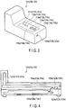
- FIG. 3 is a perspective view showing an example of an appearance of the test device 101, 102, or 103.
- the appearance of the test device 101 is substantially a rectangular solid having a protrusion on an upper part.
- the test device 101 will be explained here.
- a final letter "a" of a reference numeral indicates a constituent element of the test device 101
- a final letter "b” of a reference numeral indicates a constituent element of the test device 102
- a final letter "c” of a reference numeral indicates a constituent element of the test device 103.
- An LED/button area 116a is located on an upper surface of the test device 101.
- a Wi-Fi/Bluetooth LED (W/B LED) 111a, a ZigBee LED (ZB LED) 112a, a system/power state LED (S/P LED) 113a, a connect button 114a, and a power button 115a are located in the LED/button area 116a.
- the W/B LED 111a notifies the worker of the state of ZigBee communication of the test device 101 by lighting in various lighting modes.
- the ZB LED 112a notifies the worker of the state of ZigBee communication of the test device 101 by lighting in various lighting modes.
- the S/P LED 113a notifies the worker of the on-off state of the test device 101 and the state of battery by lighting in various lighting modes.
- the connect button 114a is a switch to establish wireless communication links with the other test devices. Measurement of ZigBee communication with the other test devices can be executed by pressing the connect button 114a.
- the power button 115a is used to turn on or turn off the power of the test device 101.
- a connector terminal 123a is a terminal insertion opening for connection with an external device.
- the connector terminal 123a may be a terminal conforming to USB standards.
- FIG. 4 is a view showing an example of the inside of the test device 101, 102, or 103 as seen from the side.
- the test device 101 includes the LED/button area 116a, a ZigBee antenna (ZB antenna) 121a, Wi-Fi/Bluetooth antenna (W/B antenna) 122a, the connector terminal 123a, a battery 124a, and the like.
- ZB antenna ZigBee antenna
- W/B antenna Wi-Fi/Bluetooth antenna
- the W/B LED 111a, the ZB LED 112a, the S/P LED 113a, the connect button 114a, and the power button 115a are located in the LED/button area 116a.
- the ZB antenna 121a is used when the test device 101 mutually executes ZigBee communication with the other communication device.
- test device 101 transmits various signals such as a test signal by executing ZigBee communication
- the test device 101 transmits the signals via the ZB antenna 121a.
- the W/B antenna 122a is used when the test device 101 mutually executes Wi-Fi communication or Bluetooth communication with the other communication device.
- the test device 101 transmits data such as the test result by using Wi-Fi communication or Bluetooth communication
- the test device 101 transmits the data via the W/B antenna 122a.
- the battery 124a supplies power necessary for the operation of the test device 101.
- the battery 124a is a rechargeable battery and is charged by a charger 132a that will be explained below.
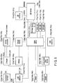
- FIG. 5 is an exemplary circuit block diagram showing the test device 101, 102, or 103.
- the test device 101 will be explained here.
- USB detector 131a supplies DCP_DE signal to the charger 132a.
- the charger 132a receives the DCP_DE signal, the charger 132a can charge the battery 124a fast with a large current.
- a voltage (battery voltage VBAT) at which the charger 132a charges the battery 124a is about 4.5V to 3.5V.
- the charger 132a supplies system voltage VSYS to a DC/DC converter 133a.
- the DC/DC converter 133a supplies 3.3V voltage to each device in the test device 101.
- a gauge device 134a measures remaining power of the battery 124a.
- the lighting mode of the S/P LED 113a is varied in response to the measured remaining power.
- a switch 144a is operated in response to an operation of the connect button 114a.
- a switch 145a corresponds to the power button 115a.
- main MCU main micro controller unit
- a long press reset device 140a supplies a reset signal to the main MCU 136a.
- a storage device 137a In a storage device 137a, data such as the contents of the wireless communication test, the result of the wireless communication test, identification numbers of the other test devices, and the number of the channel on which link setting is succeeded, and a program 138a are stored.
- An example of the storage device 137a may be a flash memory.
- the main MCU 136a executes whole control of the test device 101.
- the main MCU 136a executes various operations by reading the program 138a stored in the storage device 137a.
- the various operations include, for example, operations relating to the pre-test setting operation, operations relating to the wireless communication test, operations relating to updating of the contents of the wireless communication test, and operations relating to the transmission of the test results to the communicator 105A in the service van 105.
- the main MCU 136a will be explained below in detail.
- a ZB device 139a is communication means for the test device 101 to execute ZigBee communication with the external device, and mutually executes ZigBee communication with the external device via the ZB antenna 121a.
- the external device means the other test device.
- the ZB device 139a can execute ZigBee communication in the 2.4 GHz frequency band.
- the ZB device 139a can execute ZigBee communication in the 868 MHz frequency band.
- the ZB device 139a and the ZB antenna 121a capable of executing communication in both of the 2.4 GHz frequency band and the 868 MHz frequency band are shown in FIG. 5 , but the test device 101 may include a ZB device and a ZB antenna capable of executing communication in the 2.4 GHz frequency band, and a ZB device and a ZB antenna capable of executing communication in the 868 MHz frequency band.
- the test device 101 can execute Wi-Fi communication or Bluetooth communication with the external device. Selection of Wi-Fi communication or Bluetooth communication is determined by the operation terminal 104.
- the test device 101 can execute Bluetooth communication with the operation terminal 104 via the W/B antenna 122a when the operation terminal 104 establishes Bluetooth connection with the test device 101, and test device 101 can execute Wi-Fi communication with the operation terminal 104 via the W/B antenna 122a when the operation terminal 104 establishes Wi-Fi connection with the test device 101.
- the W/B LED 111a, the ZB LED 112a, and the S/P LED 113a are connected to the main MCU 136a.
- the lighting mode of each LED is controlled by the main MCU 136a.
- FIG. 6A is a block diagram showing an example of a functional configuration of the wireless communication test system 100.
- FIG. 6B is an exemplary block diagram showing a functional configuration of the operation terminal 104 shown in FIG. 6A .
- the operation terminal 104 includes a control device 500, a communication device 510, a storage device 520, a display unit 104a, and the like.
- the control device 500 executes whole control of the operation terminal 104.
- the control device 500 executes operations relating to a pre-test setting operation, operations relating to the wireless communication test, operations relating to updating of the contents of the wireless communication test, operations relating to the transmission of the test results to the communicator 105A in the service van 105, and the like, by reading a program 521 stored in the storage device 520.
- the control device 500 includes a communication control unit 501, a setting unit 502, an instruction transmitting unit 503, a test result receiving unit 504, a display control unit 505, an update instructing unit 506, a test result transmitting unit 507, an upload unit 508, as functional units that implement the wireless communication test system.
- the communication control unit 501 executes an operation for establishing communication between the operation terminal 104 and the test devices 101, 102, and 103.
- the setting unit 502 sets the test devices 101, 102, and 103 to a first device mode or a second device mode. More specifically, the setting unit 502 sets one of the plural test devices 101, 102, and 103 to the first device mode and sets the remaining test devices to the second device mode.
- the wireless communication test is executed, based on a test instruction from the operation terminal 104.
- the test instruction makes the test device execute the wireless communication test.
- a test device set to the first device mode is hereinafter called an initiator device.
- a response signal is transmitted in response to a degree of reception of the test signal to the initiator device when the test signal is received from the initiator device.
- the test signal is transmitted from the initiator device to a beacon device when the wireless communication test is executed.
- the response signal will be explained below.
- the test device set to the second device mode is hereinafter called a beacon device.
- FIG. 6A shows a case where the test device 101 functions as the initiator device, the test device 102 functions as the first beacon device, and the test device 103 functions as the second beacon device.
- the instruction transmitting unit 503 transmits a test instruction to the initiator device 101.
- the test instruction makes the initiator device 101 execute a test for determining whether the initiator device 101 and the beacon device 102 or 103 are capable of mutually executing wireless communication in the 2.4 GHz frequency band or not. Further, the instruction transmitting unit 503 transmits a test instruction to make the initiator device 101 execute a test for determining whether the initiator device 101 and the beacon device 102 or 103 are capable of mutually executing wireless communication in the 868 MHz frequency band or not, to the initiator device 101. Furthermore, the instruction transmitting unit 503 transmits an instruction to make the initiator device 101 end the wireless communication test executed by the initiator device 101 to the initiator device 101.
- the test result receiving unit 504 receives the result of the wireless communication test executed by the initiator device 101 from the initiator device 101.
- the display control unit 505 displays various screens on the display unit 104a.
- the display unit 104a also includes a function of input means and can detect a touch operation.
- the operation terminal 104 is a PC that includes a keyboard
- the display unit 104a may not include the function of input means.
- the update instructing unit 506 transmits an update instruction of contents of the test executed by the initiator device 101 (test contents update instruction) to the initiator device 101.
- the update instruction includes updated contents of the wireless communication test stored in the storage device 520.
- the updated contents of the wireless communication test may be information that is downloaded from the server 106 or may be information that is transmitted from the communicator 105A in the service van 105.
- the test result transmitting unit 507 transmits the result of the wireless communication test acquired from the initiator device 101 to the communicator 105A in the service van 105.
- the upload unit 508 uploads the result of the wireless communication test acquired from the initiator device 101 to the server 106.
- the communication device 510 is a communication means for the operation terminal 104 to mutually execute communication with the external device. More specifically, the communication device 510 can execute communication with the external device by using not only a cellular telephone communication function such as 3G/LTE, but Wi-Fi communication function or Bluetooth communication function.
- the external device may include the test devices 101, 102, and 103, communicator 105A in the service van 105, server 106 or the like.
- the storage device 520 stores data such as the result of the wireless communication test received from the initiator device, the contents of the wireless communication test, the updated contents of the wireless communication test, and identification numbers of the test devices used in the wireless communication test, and the above-mentioned program 521.
- FIG. 6C is an exemplary block diagram showing a functional configuration of communicator 105A in the service van of FIG. 6A .
- the communicator 105A includes a control device 600, a communication device 610, a storage device 620, and the like.
- the control device 600 executes whole control of the communicator 105A. More specifically, the control device 600 executes operations relating to updating of the contents of the wireless communication test, operations relating to collection and processing of the wireless communication test, and the like by reading a program 621 stored in the storage device 620.
- the control device 600 includes a test result acquisition unit 601, an upload unit 602, and a test contents transmitting unit 603, as functional units that implement the wireless communication test system.
- the test result acquisition unit 601 acquires the result of the wireless communication test from the operation terminal 104 or the initiator device 101.
- the upload unit 602 uploads the result of the wireless communication test acquired from the initiator device 101 or the operation terminal 104 to the server 106.
- the test contents transmitting unit 603 transmits the uploaded contents of the wireless communication test that is to be executed by the initiator device 101 to the operation terminal 104.
- the updated contents of the wireless communication test may be information that is downloaded from the server 106.
- the communication device 610 is a communication means for the communicator 105A to mutually execute communication with the external device.
- the communication device 610 can execute communication with the external device by using not only a cellular telephone communication function such as 3G/LTE, but Wi-Fi communication function, Bluetooth communication function, and the like.
- the external device may include the initiator device 101, the operation terminal 104, the server 106 or the like.
- data such as the contents of the wireless communication test including the updated contents of the wireless communication test, the result of the wireless communication test, and the like, and the above-mentioned program 621 are stored.
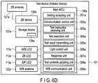
- FIG. 6D is an exemplary block diagram showing a functional configuration of the test device 101 (initiator device) of FIG. 6A .
- FIG. 6E is an exemplary block diagram showing a functional configuration of the test device 102 or 103 (beacon device) of FIG. 6A .
- the main MCU 136a of the test device 101 includes a setting accepting unit 301a, a communication control unit 302a, a test instruction receiving unit 303a, a test execution unit 304a, a test result transmitting unit 305a, an light control unit 306a, a response unit 307a, a test contents updating unit 308a, Wi-Fi/Bluetooth (W/B) communication unit 309a, and the like, as functional units that execute the operations relating to the pre-test setting operation, the operations relating to the wireless communication test, the operations relating to updating of the contents of the wireless communication test, the operations relating to transmission of the test results to the communicator 105A in the service van 105, and the like.
- W/B Wi-Fi/Bluetooth
- the setting accepting unit 301a sets the device mode of the test device 101 in accordance with a device mode setting signal transmitted from the operation terminal 104.
- the communication control unit 302a executes an operation for establishing wireless communication for each of the first beacon device 102 and the second beacon device 103.
- the communication control unit 302a establishes the wireless communication for each of the first beacon device 102 and the second beacon device 103 via the ZB antenna 121a, by controlling the ZB device 139a.
- the test instruction receiving unit 303a receives the test instruction from the operation terminal 104.
- the test execution unit 304a executes the wireless communication test, based on the test instruction from the operation terminal 104.
- the test execution unit 304a executes the wireless communication test in the 2.4 GHz frequency band if the test instruction is an instruction for making initiator device 101 execute the wireless communication test in the 2.4 GHz frequency band, and executes the wireless communication test in the 868 MHz frequency band if the test instruction is an instruction for making initiator device 101 execute the wireless communication test in the 868 MHz frequency band.
- the test result transmitting unit 305a transmits the result of the wireless communication test executed by the test execution unit 304a to the operation terminal 104.
- the test result transmitting unit 305a transmits the result of the wireless communication test to the communicator 105A in the service van 105.
- the light control unit 306a makes the W/B LED 111a, the ZB LED 112a, and the S/P LED 113a light in a predetermined lighting mode.
- the response unit 307a when the response unit 307a receives the test signal from the initiator device, the response unit 307a transmits a response signal corresponding to the degree of reception of the test signal to the initiator device.
- the whole test signal from the initiator device is correctly received (when the degree of reception is high) in some cases, and only a part of test signal is correctly received (when the degree of reception is low) in the other cases. Even if the initiator device transmits the test signal, the whole test signal may be received by the beacon device (the degree of reception is zero).
- the response unit 307a transmits to the initiator device the response signal different in a case where the degree of reception is high and a case where the degree of reception is low.
- test contents updating unit 308a When receiving an instruction to update the contents of the wireless communication test (test contents update instruction) from the operation terminal 104, the test contents updating unit 308a updates the contents of the wireless communication test to new contents, based on the update instruction.
- the W/B communication unit 309a controls Wi-Fi communication and Bluetooth communication with the external device.
- the W/B communication unit 309a mutually executes Wi-Fi communication and Bluetooth communication with the external device via the W/B antenna 122a.
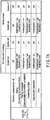
- FIG. 7A is a table showing an example of a lighting mode of the W/B LED 111a provided in the test device 101, the W/B LED 111b provided in the test device 102, and the W/B LED 111c provided in the test device 103.
- FIG. 7B is a table showing an example of a lighting mode of the ZB LED 112a provided in the test device 101, the ZB LED 112b provided in the test device 102, and the ZB LED 112c provided in the test device 103.
- FIG. 7C is a table showing an example of a lighting mode of the S/P LED 113a provided in the test device 101, the S/P LED 113b provided in the test device 102, and the S/P LED 113c provided in the test device 103.
- the lighting mode includes blinking or no blinking, frequency of blinking, color at lighting, and the like.
- the test device 101 will be explained here.
- FIG. 7A shows the lighting mode of the W/B LED 111a in each of the states of the test device, i.e., system-on in the AC mode, system-off in the AC mode, system-on in the battery mode, and system-off state in the battery mode.
- the AC mode indicates a power supply mode in which power is supplied from an external power source and the test device can operate with the power supplied from the external power source.
- the AC mode indicates a power supply mode for supplying supplied power to the battery 124a and charging the battery 124a.
- the battery mode indicates a power supply mode in which power is not supplied from the external power source and the test device can operate with the power supplied from the battery 124a.
- the lighting mode of the W/B LED 111a are classified into states of the test device 101, i.e., wireless communication-off, pairing (connecting for communication), pairing completed (communication connection completed), transferring of data, data transfer completed, and error.
- the wireless communication indicates wireless communication using Wi-Fi or Bluetooth communication function. Pairing indicates an operation of establishing communication with the external device. Error indicates a state in which Wi-Fi communication or Bluetooth communication is failed.
- the W/B LED 111a blinks in amber or green with a low frequency, irrespective of the AC mode or the battery mode of the test device 101.
- the W/B LED 111a may blink at the low frequency in a lighting mode of alternately repeating lighting in amber and lighting in green.
- the W/B LED 111b in the test device 102 and the W/B LED 111c in the test device 103 are also in the lighting mode similarly to the W/B LED 111a.
- FIG. 7B shows the lighting mode of the ZB LED 112a in each of the states of the test device 101, i.e., system-on in the AC mode, system-off in the AC mode, system-on in the battery mode, and system-off state in the battery mode.
- the lighting mode of the ZB LED 112a is defined based on the states of the test device 101, i.e., ZigBee wireless communication-off, pairing, pairing completed, transferring of data (including test), data transfer (including test) completed, and error. Error indicates a state in which ZigBee communication is failed.
- the ZB LED 112a blinks in green with a low frequency, irrespective of the AC mode or the battery mode of the test device 101.
- FIG. 7C shows the lighting mode of the S/P LED 113a in the states of the test device 101, i.e., system-on in the AC mode, system-off in the AC mode, system-on in the battery mode, and system-off state in the battery mode.
- the lighting mode of the S/P LED 113a is defined based on the states of the test device 101, i.e., power-on, power-off, charging battery, fully charged battery, low battery, and system error.
- the S/P LED 113a lights in green irrespective of the AC mode or the battery mode of the test device 101. If the test device 101 is in the system-off state in the AC mode and if the battery 124a is charging, the S/P LED 113a blinks in amber with a low frequency. If the test device 101 is in the system-off state in the AC mode and if the battery 124a is fully charged, the S/P LED 113a lights in amber. If the test device 101 is in the system-on state in the battery mode and if the battery 124a is a state of a low battery, the S/P LED 113a blinks in amber with a high frequency.
- the S/P LED 113a blinks in green with a high frequency.
- the lighting mode the S/P LED 113a differs in states, i.e., the power-on state, charge states of the battery 124a, and the system error state.
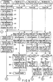
- FIG. 8 and FIG. 9 are sequence diagrams showing a pre-test setting operation executed by the wireless communication test system 100. It is assumed that the worker executes the pre-test setting operation with three test devices 101, 102, and 103.
- the pre-test setting operation indicates a setting operation that is to be executed for each of the test devices 101, 102, and 103 before executing the wireless communication test.
- the display control unit 505 displays an initial screen as shown in FIG. 10A on the display unit 104a of the operation terminal 104 (step A1).
- a start initiator button 202 on the initial screen will be explained later.
- the worker turns on power of the test devices 101, 102, and 103 by pressing the power buttons 115a, 115b, and 115c (steps B1, C1, and D1).
- step A3 When the worker touches a start pairing button 201 on the initial screen (step A2), the display control unit 505 displays a capture screen as shown in FIG. 10B on the display unit 104a (step A3).
- the worker determines one of the test devices 101, 102, and 103 as the initiator device and determines remaining two devices as the beacon devices.
- the worker determines the test device 101 as the initiator device, and also determines the test devices 102 and 103 as the first beacon device and the second the beacon device, respectively.
- the workers inputs identification numbers of the respective test devices 101, 102, and 103 to the operation terminal 104 (step A4).
- the worker touches a field 213 of the initiator device on the capture screen and inputs identification number 213a of the test device 101, touches a field 214 of the first beacon device and inputs identification number 214a of the test device 102, and touches a field 215 of the second beacon device and inputs identification number 215a of the test device 103.
- the identification numbers may be printed as bar cords on the test devices 101, 102, and 103 and the identification numbers may be input to the operation terminal 104 by reading the bar codes with the operation terminal 104.
- the worker may input the identification numbers to the operation terminal 104 by a worker's input operation.
- the identification numbers may be input to the operation terminal 104 by Near Field Communication (NFC) function.
- NFC Near Field Communication
- the test device 101 may activate the NFC function if, for example, the connect button 114a and the power button 115a are long-pressed simultaneously.
- the NFC function activating method is the same in the test devices 102 and 103.
- the input identification numbers 213a, 214a, and 215a are stored in the storage device 520.
- the identification numbers 213a, 214a, and 215a are input, the identification numbers 213a, 214a, and 215a of the test devices 101, 102, and 103 are displayed in the fields 213, 214, and 215 on the capture screen, respectively.
- the communication control unit 501 of the operation terminal 104 establishes links between the operation terminal 104 and the test device 101, between the operation terminal 104 and the test device 102, and between the operation terminal 104 and the test device 103, in Bluetooth communication, via the communication device 510 (step A6).
- Device names/passwords based on the identification numbers 213a, 214a, and 215a stored in the storage device 520 may be used for the link establishment.
- the setting unit 502 sets the initiator device 101 to the first device mode (operating as the initiator device), and sets the test devices 102 and 103 to the second device mode (operating as beacon devices). More specifically, the setting unit 502 transmits a first device mode setting signal for setting the first device mode to the test device 101, and transmits a second device mode setting signal for setting the second device mode to the test devices 102 and 103, via the communication device 510.
- the setting accepting unit 301a receives the first device mode setting signal, in the test device 101, the test device 101 is set to the first device mode in accordance with the first device mode setting signal.
- the setting accepting unit 301a returns a first device mode setting complete signal indicating that the device mode setting is completed, to the operation terminal 104.
- the test devices 102 and 103 when the setting accepting units 301b and 301c receive the second device mode setting signal, the test devices 102 and 103 are set to the second device mode in accordance with the second device mode setting signal, respectively.
- each of the setting accepting units 301b and 301c returns second device mode setting complete signal indicating that the device mode setting is completed, to the operation terminal 104.
- the light control unit 306a of the test device 101 makes the W/B LED 111a blink in green at a low frequency (step B2).
- the light control unit 306b of the test device 102 makes the W/B LED 111b blink in green at a low frequency (step C2).
- the light control unit 306c of the test device 103 makes the W/B LED 111c blink in green at a low frequency (step D2).
- the W/B LED 111a, W/B LED 111b, and W/B LED 111c may blink in not green, but amber (see FIG. 7A ).
- the W/B LED 111a, W/B LED 111b, and W/B LED 111c may blink at a low frequency in a lighting mode of alternately repeating lighting in amber and lighting in green.
- the light control unit 306a of the test device 101 makes the W/B LED 111a light in green (step B3).
- the light control unit 306b of the test device 102 makes the W/B LED 111b light in green if the establishment of the link between the operation terminal 104 and the test device 102 is succeeded (step C3).
- the light control unit 306c of the test device 103 makes the W/B LED 111c light in green if the establishment of the link between the operation terminal 104 and the test device 103 is succeeded (step D3).
- the W/B LED 111a, W/B LED 111b, and W/B LED 111c may light in not green, but amber (see FIG. 7A ).
- the light control unit 306a may make the W/B LED 111a blink in green at a high frequency.
- the light control unit 306b may make the W/B LED 111b blink in green at a high frequency if the establishment of the link between the operation terminal 104 and the test device 102 is failed.
- the light control unit 306c may make the W/B LED 111c blink in green at a high frequency if the establishment of the link between the operation terminal 104 and the test device 103 is failed.
- the W/B LED 111a, W/B LED 111b, and W/B LED 111c may blink at a high frequency in a lighting mode of alternately repeating lighting in amber and lighting in green. If the link establishment is failed, the capture screen may be displayed on the display unit 104a in the operation terminal 104. Then, when the worker touches the pair initial button 211, the above-mentioned link establishment operation may be executed again.
- the display control unit 505 displays a pairing complete screen as shown in FIG. 10C on the display unit 104a of the operation terminal 104 (step A7).
- a connect button 221, a close button 222, and a message 223 indicating that the pairing is completed are displayed.
- the communication control unit 501 transmits an address of the first beacon device 102 and an address of the second beacon device 103 to the initiator device 101 via the communication device 510 (step A9).
- the addresses may be identification number 214a of the first beacon device 102 and identification number 215a of the second beacon device 103, which are input to the operation terminal 104 by the worker.
- the initiator device 101 When the initiator device 101 receives the address of the first beacon device 102 and the address of the second beacon device 103 (step B4), the received addresses (i.e., the identification number 214a of the first beacon device 102 and the identification number 215a of the second beacon device 103) are supplied to the storage device 137a and stored in the storage device 137a. Then, the communication control unit 302a of the initiator device 101 executes the operation for establishing the wireless communication for the first beacon device 102 and the second beacon device 103, i.e., link settings (pairing) with the first beacon device 102 and the second beacon device 103 via ZigBee communication (step B5). The communication control unit 302a may first attempt the link setting using a default channel via ZigBee communication. If the link setting using the default channel is failed, link setting may be sequentially attempted by using different channels.
- the communication control unit 302a may first attempt the link setting using a default channel via ZigBee communication. If the link setting using the default channel is
- the light control unit 306b of the first beacon device 102 makes the ZB LED 112b blink in green at a low frequency (step C4)
- the light control unit 306c of the second beacon device 103 makes the ZB LED 112c blink in green at a low frequency (step D4).
- step C5 If the link setting between the initiator device 101 and the first beacon device 102 is succeeded (YES in step C5), a channel number corresponding to the succeeded channel is supplied to the storage device 137a of the initiator device 101 and the storage device 137b of the first beacon device 102 and stored in the storage device 137a and the storage device 137b. Then, the light control unit 306b makes the ZB LED 112b light in green (step C6). If the link setting is failed (NO in step C5), the light control unit 306b makes the ZB LED 112b blink in green at a high frequency (step C7).
- step D5 if the link setting between the initiator device 101 and the second beacon device 103 is succeeded (YES in step D5), a channel number corresponding to the succeeded channel is supplied to the storage device 137a of the initiator device 101 and the storage device 137c of the second beacon device 103 and stored in the storage device 137a and the storage device 137c. Then, the light control unit 306c makes the ZB LED 112c light in green (step D6). If the link setting is failed (NO in step D5), the light control unit 306c makes the ZB LED 112c blink in green at a high frequency (step D7).
- the worker may press the connect button 114a of the initiator device 101 instead of touching the connect button 221 on the pairing setting screen.
- the communication control unit 302a of the initiator device 101 executes the link setting (pairing) with the first beacon device 102 and the second beacon device 103 via ZigBee communication, respectively.
- the worker can execute the wireless communication test between the initiator device 101 and the first beacon device 102, and between the initiator device 101 and the second beacon device 103 by operating the connect button 114a, in the state in which Bluetooth communication between the operation terminal 104 and the initiator device 101 is disconnected, which will be explained later.
- the channel number corresponding to the channel on which the link setting between the initiator device 101 and the first beacon device 102 is succeeded may be different from the channel number corresponding to the channel on which the link setting between the initiator device 101 and the second beacon device 103 is succeeded. In this case, the channel number corresponding to each of the channels on which the link setting is succeeded is stored.
- the W/B communication unit 309a transmits the results of the link settings via ZigBee communication to the operation terminal 104 (step B6).
- the display control unit 505 displays a success/failure message screen as shown in FIG. 10D or FIG. 10E on the display unit 104a (step A10).
- the predetermined operation may be, for example, the operation of the worker touching the connect button 221 or the close button 222 on the pairing complete screen ( FIG. 10C ).
- the success/failure message screen as shown in FIG. 10D indicates an example of a case where the link settings between the initiator device 101 and the first beacon device 102 and between the initiator device 101 and the second beacon device 103 via ZigBee communication are succeeded.
- the success/failure message screen as shown in FIG. 10D displays a message 231 indicating that the link settings (pairing) between the initiator device 101 and the first beacon device 102 and between the initiator device 101 and the second beacon device 103 via ZigBee communication are completed, a message 232 indicating that the link settings are succeeded, channel information 233, and a close button 234.
- the channel information 233 includes a channel number corresponding to the channel on which the link settings between the initiator device 101 and the first beacon device 102 and between the initiator device 101 and the second beacon device 103 are succeeded.
- FIG. 10D indicates an example of a case where the link settings between the initiator device 101 and the first beacon device 102 and between the initiator device 101 and the second beacon device 103 in the 2.4 GHz frequency band are succeeded. If the link setting is failed, the success/failure message screen as shown in FIG. 10E is displayed on the display unit 104a. The success/failure message screen shown in FIG. 10E displays a message 241 indicating that the link setting is failed and a connect button 242.
- step A11 If the link setting is succeeded, the worker touches the close button 234 (NO in step A11 and YES in step A12), and the pre-test setting operation is ended. If the link setting is failed, the worker touches the connect button 242 on the success/failure message screen (YES in step A11). The flow goes back to step A7.
- the link setting between the initiator device 101 and the first beacon device 102 may be succeeded and the link setting between the initiator device 101 and the second beacon device 103 may be failed.
- the results of the link setting between the initiator device 101 and the second beacon device 102 and the link setting between the initiator device 101 and the second beacon device 103 may be displayed separately on the success/failure message screen ( FIG. 10E ).
- the worker touches the connect button 242 the flow may return to step A7 and the only link setting between the initiator device 101 and the second beacon device 103, i.e., the beacon device with which the initiator device 101 fails the link setting may be executed again.
- ZigBee communication between the initiator device 101 and the first beacon device 102 and between the initiator device 101 and the second beacon device 103 can be mutually executed by the above-explained link setting via ZigBee communication.
- a link may be established via Wi-Fi communication.
- the test device 101 is set as the initiator device, and the test devices 102 and 103 are set as the first beacon device and the second beacon device, respectively, and the test deice 101 can mutually execute ZigBee communication with each of the test devices 102 and 103, by completing the above-explained pre-test setting operation.
- the test device 102 executes the same operation as the above-explained operation of the initiator device
- the test device 103 executes the same operation as the above-explained operation of the first beacon device
- the test device 101 executes the same operation as the above-explained operation of the second beacon device.
- the same operations are executed in a case where the test device 103 is set as the initiator device and the test devices 101 and 102 are set as the first beacon device and the second beacon device, respectively.
- two beacon devices are used, but one or three or more beacon devices may be used.
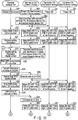
- FIG. 11 and FIG. 12 are sequence diagrams showing operations relating to the wireless communication test executed by the wireless communication test system 100. It is assumed that the pre-test setting operations shown in FIG. 8 and FIG. 9 have been completed. That is, it is assumed that the test device 101 is set as the initiator device, the test device 102 is set as the first beacon device, the test device 103 is set as the second beacon device, and the test device 101 completes the communication setting (pairing) with the test devices 102 and 103.
- test device 102 or 103 other than the test device 101 is set as the initiator device while the remaining test devices are set as the beacon devices, too, the same operations are executed.
- the display control unit 505 displays an initial screen as shown in FIG. 13A on the display unit 104a of the operation terminal 104 (step A21).
- the worker turns on the power of the first beacon device 102 and the second beacon device 103 (steps C21 and D21).
- the communication control unit 302a of the initiator device 101 starts ZigBee connection between the initiator device 101 and the first beacon device 102 and ZigBee connection between the initiator device 101 and the second beacon device 103 (step B22).
- the communication control unit 302a establishes ZigBee connection with the first beacon device 102 and ZigBee connection with the second beacon device 103, using the identification numbers 214a and 215a stored in the storage device 137a.
- the light control unit 306b of the first beacon device 102 makes the ZB LED 112b blink in green at a low frequency (step C22), and the light control unit 306c of the second beacon device 103 makes the ZB LED 112c blink in green at a low frequency (step D22).
- the light control unit 306b of the first beacon device 102 makes the ZB LED 112b light in green (step C23).
- the light control unit 306c of the second beacon device 103 makes the ZB LED 112c light in green (step D23).
- the communication control unit 302a of the initiator device 101 establishes Bluetooth connection between the initiator device 101 and the operation terminal 104 (step B22).
- the light control unit 306a of the initiator device 101 makes the W/B LED 111a blink in green at a low frequency (step B23).
- the W/B LED 111a may blink in not green, but amber (see FIG. 7A ).
- the W/B LED 111a may blink at a low frequency in a lighting mode of alternately repeating lighting amber and lighting green.
- the light control unit 306a of the initiator device 101 makes the W/B LED 111a light in green (step B24).
- the W/B LED 111a may light in not green, but amber (see FIG. 7A ).
- the communication control unit 501 When the worker touches the start initiator button 202 (step A22), the communication control unit 501 requires the initiator device 101 to transmit setting information (step A23).
- the communication control unit 302a of the initiator device 101 When receiving the request for transmission of the setting information from the operation terminal 104, the communication control unit 302a of the initiator device 101 transmits the setting information including the identification number 214a of the first beacon device 102, the identification number 215a of the second beacon device 103, and the channel number stored in the storage device 137a, to the operation terminal 104 (step B25).
- the identification number 213a of the initiator device 101 may also be transmitted to the operation terminal 104.
- the display control unit 505 of the operation terminal 104 displays a setting information display screen as shown in FIG. 13B on the display unit 104a (step A24).
- the identification number 213a of the initiator device 101 is displayed in field 314 of the initiator device 101 of the setting information display screen.
- the identification number 214a of the first beacon device 102 is displayed in a field 315 of the first beacon device 102 of the setting information display screen.
- the identification number 215a of the second beacon device 103 is displayed in a field 316 of the second beacon device 103 of the setting information display screen.
- Information 313 including the received channel number is displayed on the setting information display screen.
- step B25 is executed when the worker presses the connect button 114a of the initiator device 101. After that, step A24 is executed on the operation terminal 104 side.
- the worker arranges the initiator device 101 at or near the location where the communication hub 20 is to be installed, the first beacon device 102 at or near the location where, for example, the gas meter 2 is to be installed, and the second beacon device 103 at or near the location where the IHD 4 is to be installed.
- the instruction transmitting unit 503 transmits to the initiator device 101 a first test instruction to make the initiator device 101 execute a first test, and a third test instruction to make the initiator device 101 execute a third test for determining whether the initiator device 101 and the second beacon device 103 are capable of wireless communication with each other in the 2.4 GHz frequency band or not (step A26).
- the first test is a test for determining whether the initiator device 101 and the first beacon device 102 are capable of mutually executing wireless communication in the 2.4 GHz frequency band or not.
- the third test is a test for determining whether the initiator device 101 and the second beacon device 103 are capable of mutually executing wireless communication in the 2.4 GHz frequency band or not.
- the display control unit 505 displays a stop HAN survey screen as shown in FIG. 13C on the display unit 104a (step A27).
- the stop HAN survey screen displays a stop HAN survey button 321 and a close button 322.
- the test execution unit 304a executes the first test when the test instruction receiving unit 303a of the initiator device 101 receives the first test instruction.
- the test execution unit 304a executes the third test when the test instruction receiving unit 303a receives the third test instruction (step B26).
- the test execution unit 304a periodically transmits the first test signal in the 2.4 GHz frequency band to the first beacon device 102, and periodically transmits the third test signal in the 2.4 GHz frequency band to the second beacon device 103.
- the first test signal and the third test signal include messages and data.
- a response unit 307b of the first beacon device 102 transmits a first response signal to the initiator device 101.
- a response unit 307c of the second beacon device 103 transmits a third response signal to the initiator device 101.
- Examples of the first and third response signals include ACK and Selective ACK.
- Each of the first response signal transmitted from the response unit 307b when the first beacon device 102 correctly receives the first test signal (i.e., the degree of reception is high), and the third response signal transmitted from the response unit 307c when the second beacon device 103 correctly receives the third test signal (i.e., the degree of reception is high) is ACK.
- ACK indicates a signal indicative of positive contents, which is transmitted from the data receiving side to the data transmitting side.
- each of the first response signal transmitted from the response unit 307b to the initiator device 101 when the first beacon device 102 correctly receives only a part of the first test signal (i.e., the degree of reception is low), and the third response signal transmitted from the response unit 307c to the initiator device 101 when the second beacon device 103 correctly receives only a part of the third test signal (i.e., the degree of reception is low) is Selective ACK.
- Selective ACK indicates a signal indicative of the contents requiring data failed in communication to be retransmitted, which is transmitted from the data receiving side to the data transmitting side.
- the test execution unit 304a receives the first response signal and the third response signal.
- the wireless communication test is executed based on the contents of the wireless communication test stored in the storage device 137a. Details of the wireless communication test will be explained later.
- the light control unit 306a of the initiator device 101 makes the ZB LED 112a blink in green at a low frequency (step B27), and the light control unit 306b of the first beacon device 102 makes the ZB LED 112b blink in green at a low frequency (step C24).
- the light control unit 306a of the initiator device 101 makes the ZB LED 112a blink in green at a low frequency (step B27), and the light control unit 306c of the second beacon device 103 makes the ZB LED 112c blink in green at a low frequency (step D24) .
- the ZB LED 112a of the initiator device 101 may blink in green at a high frequency.
- the ZB LED 112b of the first beacon device 102 may blink in green at a high frequency, and the ZB LED 112c of the second beacon device 103 may blink in green at a high frequency.
- the instruction transmitting unit 503 of the operation terminal 104 transmits an instruction to make the initiator device 101 end the wireless communication test in the 2.4 GHz frequency band (i.e., 2.4 GHz test end instruction) to the initiator device 101 (step A29) .
- the test execution unit 304a ends the first test and the third test (step B28).
- the test execution unit 304a stops the transmission of the first test signal in the 2.4 GHz frequency band that was periodically transmitted to the first beacon device 102, and the third test signal in the 2.4 GHz frequency band that was periodically transmitted to the second beacon device 103.
- the light control unit 306a of the initiator device 101 makes the ZB LED 112a light in green (step B29).
- the light control unit 306b of the first beacon device 102 makes the ZB LED 112b light in green when the first test is ended (step C25), and the light control unit 306c of the second beacon device 103 makes the ZB LED 112c light in green when the third test is ended (step D25) .
- results of the first test and the third test are supplied to the storage device 137a and stored in the storage device 137a.
- the test result transmitting unit 305a transmits the results of the first test and the third test to the operation terminal 104 (step B30).
- Each of the results of the first test and the third test constitutes a summarized message.
- the summarized message includes information such as the type, frequency band, rate of reception, and retransmission count of the test signal (message) used in the wireless communication test.
- the display control unit 505 displays the 2.4 GHz test result display screen as shown in FIG. 13D or FIG. 13E on the display unit 104a (step A30). It is determined, based on the received test results, whether the initiator device 101 and the first beacon device 102 are capable of mutually executing ZigBee communication or not and whether the initiator device 101 and the second beacon device 103 are capable of mutually executing ZigBee communication or not.
- the screen as shown in FIG. 13D or FIG. 13E is displayed on the display unit 104a.
- FIG. 13D The screen shown in FIG. 13D is displayed when the initiator device 101 and the first beacon device 102 are capable of mutually executing (succeed) ZigBee communication in the frequency of 2.4 GHz and the initiator device 101 and the second beacon device 103 are capable of mutually executing (succeed) ZigBee communication in the frequency of 2.4 GHz.
- FIG. 13D shows an end button 331, test result information 332, information 333 indicating that installation of a single-band communication hub 20, single-band meters 1, 2, and 3, and a single-band IHD 4 is recommended, and a report button 334.
- Either of the mutual communication between the initiator device 101 and the first beacon device 102 and the mutual communication between the initiator device 101 and the second beacon device 103 may be succeeded.
- the communication is determined to be enabled (succeeded) only when both of the communications are succeeded, and the communication is determined to be disabled (failed) when either of the communications is succeeded.
- the worker is recommended to install the single-band devices.
- the screen shown in FIG. 13E is displayed when the initiator device 101 and the second beacon device 103 are not capable of mutually executing (fail) ZigBee communication in the 2.4 GHz frequency band and/or when the initiator device 101 and the second beacon device 103 are not capable of mutually executing (fail) ZigBee communication in the 2.4 GHz frequency band.
- FIG. 13E shows a sub-GHz HAN survey button 341, test result information 342, a cancel button 343, and a report button 344.
- step A31 If both of the results of the first test and the third test indicate success (YES in step A31), the worker touches the end button 331 (step A39) and ends the operations relating to the wireless communication test.
- the worker touches the sub-GHz HAN survey button 341 (step A32).
- the instruction transmitting unit 503 transmits to the initiator device 101 a second test instruction to make the initiator device 101 execute a second test, and a fourth test instruction to make the initiator device 101 execute a fourth test (step A33).
- a second test is a test for determining whether the initiator device 101 and the first beacon device 102 are capable of mutually executing wireless communication in the 868 MHz frequency band or not.
- the fourth test is a test for determining whether the initiator device 101 and the second beacon device 103 are capable of mutually executing wireless communication in the 868 MHz frequency band or not.
- the display control unit 505 displays a stop sub-GHz HAN survey screen as shown in FIG. 13F on the display unit 104a (step A34).
- the stop sub-GHz HAN survey screen displays a stop sub-GHz HAN survey button 351 and a close button 352.
- the test execution unit 304a executes the second test when the test instruction receiving unit 303a of the initiator device 101 receives the second test instruction, and the test execution unit 304a of the initiator device 101 executes the fourth test when the test instruction receiving unit 303a receives the fourth test instruction (step B31).
- the test execution unit 304a periodically transmits the second test signal in the 868 MHz frequency band to the first beacon device 102, and periodically transmits the fourth test signal in the 868 MHz frequency band to the second beacon device 103.
- the second test signal and the fourth test signal include messages and data.
- a response unit 307b of the first beacon device 102 transmits a second response signal to the initiator device 101.
- a response unit 307c of the second beacon device 103 transmits a fourth response signal to the initiator device 101.
- Examples of the second and fourth response signals include ACK and Selective ACK.
- each of the second response signal transmitted from the response unit 307b when the first beacon device 102 correctly receives only a part of the second test signal (i.e., the degree of reception is low), and the fourth response signal transmitted from the response unit 307c when the second beacon device 103 correctly receives only a part of the fourth test signal (i.e., the degree of reception is low) is Selective ACK.
- the test execution unit 304a receives the second response signal and the fourth response signal.
- the wireless communication test is executed based on the contents of the wireless communication test stored in the storage device 137a.
- the light control unit 306a of the initiator device 101 makes the ZB LED 112a blink in green at a low frequency (step B32), and the light control unit 306b of the first beacon device 102 makes the ZB LED 112b blink in green at the low frequency (step C26).
- the light control unit 306a of the initiator device 101 makes the ZB LED 112a blink in green at a low frequency (step B32), and, the light control unit 306c of the second beacon device 103 makes the ZB LED 112c blink in green at a low frequency (step D26).
- the instruction transmitting unit 503 transmits an instruction to make the initiator device 101 end the wireless communication test in the 868 MHz frequency band (i.e., 868 MHz test end instruction) to the initiator device 101 (step A36).
- the test execution unit 304a ends the second test and the fourth test that is being executed (step B33).
- the test execution unit 304a stops the transmission of the second test signal in the 868 MHz frequency band that was periodically transmitted to the first beacon device 102, and the fourth test signal in the 868 MHz frequency band that was periodically transmitted to the second beacon device 103.
- the light control unit 306a of the initiator device 101 makes the ZB LED 112a light in green (step B34).
- the light control unit 306b of the first beacon device 102 makes the ZB LED 112b light in green when the second test is ended (step C27), and the light control unit 306c of the second beacon device 103 makes the ZB LED 112c light in green when the fourth test is ended (step D27).
- results of the second test and the fourth test are supplied to the storage device 137a and stored in the storage device 137a.
- the test result transmitting unit 305a transmits the results of the second test and the fourth test to the operation terminal 104 (step B35).
- Each of the results of the second test and the fourth test constitutes a summarized message.
- the summarized message includes information such as the type, frequency band, rate of reception, and retransmission count of the test signal (message) used in the wireless communication test.
- the display control unit 505 displays an 868 MHz test result display screen as shown in FIG. 13G or FIG. 13H on the display unit 104a (step A37). It is determined, based on the received test results, whether the initiator device 101 and the first beacon device 102 are capable of mutually executing ZigBee communication or not and whether the initiator device 101 and the second beacon device 103 are capable of mutually executing ZigBee communication or not.
- the screen shown in FIG. 13G or FIG. 13H is displayed on the display unit 104a in accordance with the determination results.
- FIG. 13G The screen shown in FIG. 13G is displayed when the initiator device 101 and the first beacon device 102 are capable of mutually executing (succeed) ZigBee communication in the frequency of 868 MHz and when the initiator device 101 and the second beacon device 103 are capable of mutually executing (succeed) ZigBee communication in the frequency of 868 MHz.
- FIG. 13G shows an end button 361, test result information 362, information 363 indicating that installation of a dual-band communication hub 20, dual-band various meters, and a dual-band IHD 4 is recommended, and a report button 364. Either of the mutual communication between the initiator device 101 and the first beacon device 102 and the mutual communication between the initiator device 101 and the second beacon device 103 may be succeeded.
- the communication is determined to be enabled (succeeded) only when both of the communications are succeeded, and the communication is determined to be disabled (failed) when either of the communications is succeeded.
- the communication is determined to be enabled (succeeded) based on the second test result and the fourth test result, the worker is recommended to install the dual-band devices.
- the screen shown in FIG. 13H is displayed when the initiator device 101 and the first beacon device 102 are not capable of mutually executing (fail) ZigBee communication in the 868 MHz frequency band and/or when the initiator device 101 and the second beacon device 103 are not capable of mutually executing (fail) ZigBee communication in the 868 MHz frequency band.
- FIG. 13H shows a retest button 371, test result information 372, information 373 indicating that retest is recommended, a report button 374, and a cancel button 375.
- step A38 If both of the results of the second test and the fourth test indicate success (YES in step A38), the worker touches the end button 361 (step A39), and then the wireless communication test system ends the operations relating to the wireless communication test.
- step A38 If at least one of the results of the second test or the fourth test indicates failure (NO in step A38), the worker touches the retest button 371 (step A40) and the flow goes back to step A24.
- the wireless communication tests at 2.4 GHz and 868 MHz are ended by operating the operation terminal 104 as shown in FIG. 11 and FIG. 12 , but the initiator device 101 itself may end the wireless communication test.
- the initiator device 101 itself may end the wireless communication test.
- the wireless communication test conforming to the contents of the wireless communication test stored in the storage device 137a is completed, the initiator device 101 itself may end the wireless communication test.
- Bluetooth communication between the operation terminal 104 and the initiator device 101 may be disconnected during the first test and the third test.
- a frequency band being used in Bluetooth communication between the operation terminal 104 and the initiator device 101 may overlap the frequency band being used in ZigBee communication (the 2.4 GHz frequency band), and the wireless communication test may not be executed appropriately. Therefore, overlapping of the frequency band being used in Bluetooth communication between the operation terminal 104 and the initiator device 101 and the frequency band being used in ZigBee communication (the wireless communication test of the 2.4 GHz) can be prevented by disconnecting Bluetooth communication.
- Bluetooth communication between the operation terminal 104 and the initiator device 101 may be disconnected during the second test and the fourth test.
- the worker presses the connect button 114a of the initiator device 101 in order to execute the wireless communication tests between the test device 101 and the test device 102 and between the test device 101 and the test device 103 in a state in which Bluetooth communication between the operation terminal 104 and the test device 101 is disconnected.
- the communication control unit 302a of the initiator device 101 transmits an instruction to make the operation terminal 104 disconnect Bluetooth connection with the initiator device 101, to the operation terminal 104.
- the communication control unit 501 disconnects Bluetooth connection between the operation terminal 104 and the initiator device 101.
- the communication control unit 302a of the initiator device 101 disconnects Bluetooth connection with the operation terminal 104.
- step B26 is executed (execution of the first test and the third test).
- step B27 is executed in the initiator device 101. If the connect button 114a is pressed during the test, the test that is being executed are canceled.
- the test execution unit 304a of the initiator device 101 ends the wireless communication test. Then, step B29 is executed in the initiator device 101. Furthermore, the communication control unit 302a establishes Bluetooth connection between the operation terminal 104 and the initiator device 101.
- the communication control unit 302a of the initiator device 101 transmits a disconnect instruction to make the operation terminal 104 disconnect Bluetooth connection with the initiator device 101, to the operation terminal 104 and, when the operation terminal 104 receives the disconnect instruction, the communication control unit 501 disconnects Bluetooth connection between the operation terminal 104 and the initiator device 101.
- the communication control unit 302a of the initiator device 101 disconnects Bluetooth connection with the operation terminal 104.
- step B31 is executed (execution of the second test and the fourth test).
- step B32 is executed in the initiator device 101. If the connect button 114a is pressed during the test, the test that is being executed are canceled.
- step B34 is executed in the initiator device 101. Furthermore, the communication control unit 302a establishes Bluetooth connection between the operation terminal 104 and the initiator device 101.
- the worker can recognize whether the wireless communication test is being executed or the wireless communication test is ended by watching the test devices.
- the instruction transmitting unit 503 may transmit only the second test instruction that relates to the first beacon device 102 to the initiator device 101, and only the second test that relates to the first beacon device 102 may be executed in relation to the wireless communication at 868 MHz.
- the instruction transmitting unit 503 may transmit only the fourth test instruction that relates to the second beacon device 103 to the initiator device 101, and only the fourth test that relates to the second beacon device 103 may be executed in relation to the wireless communication at 868 MHz.
- the instruction transmitting unit 503 may transmit only the first test instruction that relates to the first beacon device 102 to the initiator device 101, and only the first test that relates to the first beacon device 102 may be executed as the re-test. If only the result of the fourth test indicates that the wireless communication cannot be mutually executed, of the second test result and the fourth test result, the instruction transmitting unit 503 may transmit only the third test instruction that relates to the second beacon device 103 to the initiator device 101, and only the third test that relates to the second beacon device 103 may be executed as the re-test.
- the first test result and the third test result may be displayed separately on the 2.4 GHz test result display screen. If either of the second test result that relates to the first beacon device 102 and the fourth test result that relates to the second beacon device 103 indicates that the wireless communication cannot be mutually executed, the second test result and the fourth test result may be displayed separately on the 868 MHz test result display screen.
- the light control unit 306a may change the lighting mode of the ZB LED 112a in accordance with the results of the first test and the third test. For example, the light control unit 306a may make the ZB LED 112a light in green if the first test result and the third test result indicate that the wireless communication can be mutually executed, and the light control unit 306a may make the ZB LED 112a blink in green at a high frequency if the first test result and the third test result indicate that the wireless communication cannot be mutually executed.
- the light control unit 306a may make the ZB LED 112a light in green if the second test result and the fourth test result indicate that the wireless communication can be mutually executed, and the light control unit 306a may make the ZB LED 112a blink in green at a high frequency if at least one of the second test result or the fourth test result indicates that the wireless communication cannot be mutually executed.
- the light control unit 306b of the first beacon device 102 may make ZB LED 112b light in green if the test result indicates that the wireless communication can be executed, and may make the ZB LED 112b blink in green at a high frequency if the test result indicates the wireless communication cannot be mutually executed.
- the light control unit 306c of the second beacon device 103 may make the ZB LED 112c light in green if the test result indicates that the wireless communication can be executed, and may make the ZB LED 112c blink in green at a high frequency if the test result indicates the wireless communication cannot be mutually executed.
- the worker can recognize the result of the wireless communication test without operating the operation terminal 104, by watching the ZB LED of the test device.
- beacon devices are installed, but one or three or more beacon devices may be installed. In this case, the wireless communication test is executed in the same manner.
- step B30 if the report button 334 shown in FIG. 13D or the report button 344 shown in FIG. 13E is touched, the test result may be transmitted to the operation terminal 104.
- step B35 if the report button 364 shown in FIG. 13G or the report button 374 shown in FIG. 13H is touched, the test result may be transmitted to the operation terminal 104.
- FIG. 14 is a flowchart showing the wireless communication test executed by the test device that is set as an initiator device (first device mode).
- the test device 101 is set as the initiator device and the test device 102 is set as the beacon device.
- step S1 it is determined whether or not the test instruction receiving unit 303a receives a test instruction from the operation terminal 104.
- the test instruction makes the initiator device 101 execute the wireless communication test in the 2.4 GHz frequency band between the initiator device 101 and the beacon device 102 (i.e., the 2.4 GHz test instruction).
- the 2.4 GHz test instruction indicates the above-mentioned first test instruction.
- the test execution unit 304a starts the 2.4 GHz wireless communication test (2.4 GHz test) between the initiator device 101 and the beacon device 102 (step S2).
- the 2.4 GHz test indicates the above-mentioned first test.
- the 2.4 GHz test is executed based on contents of the wireless communication test stored in the storage device 137a.
- the contents of the wireless communication test include the type of the test signal such as the level of the test signal to be transmitted, a period to transmit the test signal, the time interval to transmit the test signal, and the like.
- the test execution unit 304a transmits the first test signal in the 2.4 GHz frequency band to the beacon device 102 (step S3).
- the test execution unit 304a determines a response from the beacon device 102 (step S4).
- the response unit 307b of the beacon device 102 when the response unit 307b of the beacon device 102 receives the first test signal, the response unit 307b transmits a first response signal corresponding to the degree of reception of the first test signal to the initiator device 101.
- the test execution unit 304a determines whether the first response signal is received or not and, if the first response signal is received, determines the response based on the contents (ACK or Selective ACK) of the first response signal. If the first response signal is Selective ACK, the test execution unit 304a retransmits to the beacon device 102 the data required to be transmitted in the first test signal.
- the response unit 307b transmits the first response signal to the initiator device 101 corresponding to the degree of reception of the received data.
- (1) Reception of only a part of the data by the beacon device 102, (2) transmission of Selective ACK by the beacon device 102, and (3) transmission of part of required data by the initiator device are repeated until the whole first test signal is received by the beacon device 102.
- these operations are repeated at a predetermined certain count. The number of times may be included in the contents of the wireless communication test stored in the storage device 137a.
- step S5 it is determined whether the 2.4 GHz test is ended or not. If the 2.4 GHz test is not ended (NO in step S5), the flow goes back to step S3. That is, the initiator device 101 continues transmitting the first test signal periodically for a certain period. Every time the beacon device 102 receives the first test signal, the beacon device 102 transmits the first response signal corresponding to the degree of reception of the first test signal. The first response signal is received by the initiator device 101, and a response of the beacon device 102 is determined by the test execution unit 304a.
- End of test indicates that the initiator device 101 receives from the operation terminal 104 a test end instruction to make the initiator device 101 end the wireless communication test or that the test execution unit 304a ends executing the whole contents of the wireless communication test stored in the storage device 137a.
- the 2.4 GHz test result is supplied to the storage device 137a and stored in the storage device 137a (step S6) and is transmitted to the operation terminal 104 by the test result transmitting unit 305a (step S7).
- the 2.4 GHz test result constitutes the summarized message including the information such as the type and frequency band of the test signal (message) used in the test.
- the test result is created based on the response determination in step S4.
- step S8 it is determined whether or not the test instruction receiving unit 303a of the initiator device 101 receives a test instruction from the operation terminal 104.
- the test instruction makes the initiator device 101 execute the wireless communication test in the 868 MHz frequency band between the initiator device 101 and the beacon device 102 (i.e., an 868 MHz test instruction).
- the 868 MHz test instruction indicates the above-mentioned the second test instruction.
- step S8 If the test instruction receiving unit 303a of the initiator device 101 does not receive the second test instruction (NO in step S8), the operation relating to the wireless communication test of the initiator device 101 is ended. If the initiator device 101 and the beacon device 102 are capable of mutually executing wireless communication in the 2.4 GHz frequency band, the determination of step S8 is assumed to be NO.
- test instruction receiving unit 303a of the initiator device 101 receives the 868 MHz test instruction (YES in step S8)
- the test execution unit 304a starts the 868 MHz wireless communication test (868 MHz test) between the initiator device 101 and the beacon device 102 (step S9).
- the 868 MHz test corresponds to the above-mentioned second test.
- the test of 868 MHz is executed based on contents of the wireless communication test stored in the storage device 137a.
- the test execution unit 304a transmits the second test signal in the 868 MHz frequency band to the beacon device 102 (step S10).
- the test execution unit 304a determines a response from the beacon device 102 (step S11). More particularly, when the response unit 307b of the beacon device 102 receives the second test signal, the response unit 307b transmits a second response signal corresponding to the degree of reception of the first test signal to the initiator device 101.
- the test execution unit 304a determines whether the first response signal is received or not and, if the first response signal is received, determines the response based on the contents (ACK or Selective ACK) of the first response signal.
- the test execution unit 304a retransmits the data required to be transmitted, in the second test signal, to the beacon device 102. (1) Reception of only a part of the data by the beacon device 102, (2) transmission of Selective ACK by the beacon device 102, and (3) transmission of part of required data by the initiator device are repeated until the whole second test signal are received by the beacon device 102, as explained above. Alternatively, these operations are repeated at a predetermined certain count.
- step S12 it is determined whether the test of 868 MHz is ended or not. If the test of 2.4 GHz is not ended (NO in step S12), the flow goes back to step S10. That is, the initiator device 101 continues transmitting the second test signal periodically for a certain period. Every time the beacon device 102 receives the second test signal, the beacon device 102 transmits a second response signal corresponding to the degree of reception of the second test signal to the initiator device 101. The second response signal is received by the initiator device 101, and a response of the beacon device 102 is determined by the test execution unit 304a.
- the 868 MHz test result is supplied to the storage device 137a and stored in the storage device 137a (step S13) and is transmitted to the operation terminal 104 by the test result transmitting unit 305a (step S14).
- the 868 MHz test result constitutes the summarized message including the information such as the type and frequency band of the test signal (message) used in the test.
- the test result is created based on the response determination in step S11.
- step S15 it is determined whether or not the test instruction receiving unit 303a receives the 2.4 GHz test instruction from the operation terminal 104 and, if the test instruction receiving unit 303a does not receive the 2.4 GHz test instruction from the operation terminal 104 (NO in step S15), the operation on wireless communication test of the initiator device 101 is ended. If the test instruction receiving unit 303a receives the 2.4 GHz test instruction from the operation terminal 104 (YES in step S15), the flow goes back to step S2.
- step S15 is assumed to be YES.
- the 2.4 GHz test result and the 868 MHz test result may be transmitted to not only the operation terminal 104, but also the communicator 105A in the service van 105.
- FIG. 14 does not illustrate the operation of the connect button 114a but, in step S1, it may be determined not only whether the 2.4 GHz test instruction is received or not, but also whether the connect button 114a of the initiator device 101 is pressed or not. If the connect button 114a of the initiator device 101 is pressed, the test execution unit 304a may execute the first test (the 2.4 GHz test). Similarly, in step S8, it may be determined not only whether the 868 MHz test instruction is received or not, but also whether the connect button 114a of the initiator device 101 is pressed or not. If the connect button 114a of the initiator device 101 is pressed, the test execution unit 304a may execute the second test (the 868 MHz test).
- FIG. 15 is a flowchart showing the operation responding to the wireless communication test, which is executed by the test device 102 set as the beacon device (second device mode).
- the test device 101 is set as the initiator device and the test device 102 is set as the beacon device.
- step S21 it is determined whether or not the beacon device 102 receives the first test signal in the 2.4 GHz frequency band from the initiator device 101. If the first beacon device 102 does not receive the first test signal (NO in step S21), the flow goes to step S24. If the beacon device 102 receives the first test signal from the initiator device 101 (YES in step S21), the response unit 307a responds to the first test signal based on the degree of reception of the first test signal (step S22). More particularly, the response unit 307a transmits the first response signal corresponding to the degree of the reception to the initiator device 101.
- the response unit 307a transmits the first response signal that is ACK to the initiator device 101 when correctly receiving the whole first test signal, and transmits the first response signal that is Selective ACK to the initiator device 101 when correctly receiving only a part of the first test signal. If a part of the data required by Selective ACK is received from the initiator device 101, the first response signal corresponding to the degree of reception of the data is transmitted to the initiator device 101. (1) Reception of only a part of the data by the beacon device 102, (2) transmission of Selective ACK by the beacon device 102, and (3) transmission of part of required data by the initiator device are repeated until the whole first test signal is received by the beacon device 102, as explained above, or repeated at a predetermined count.
- step S23 it is determined whether the first test signal is received or not.
- the response unit 307a responds to the first test signal based on the degree of reception of the first test signal (step S22). Step S22 is repeated until the first test signal is not received.
- step S23 If the beacon device 102 does not receive the first test signal from the initiator device 101 (NO in step S23), it is determined whether the second test signal in the 868 MHz frequency band is received or not, in step S24. If not in step S23, it is assumed that the first test (the 2.4 GHz test) by the initiator device 101 is ended.
- step S24 If the first beacon device 102 does not receive the second test signal from the initiator device 101 (NO in step S24), the operation of responding to the wireless communication test by the first beacon device 102 is ended. If the result of the 2.4 GHz wireless communication test indicates that the initiator device 101 and the first beacon device 102 are capable of mutually executing wireless communication, neither the first test or the second test is executed, or both of the first test and the second test is executed but the first beacon device 102 cannot receive any parts of the first test signal and the second test signal, the determination of step S24 is assumed to be NO.
- the response unit 307a responds to the second test signal based on the degree of reception of the second test signal (step S25).
- the response unit 307a transmits the second response signal corresponding to the degree of the reception to the initiator device 101.
- the response unit 307a transmits the second response signal that is ACK to the initiator device 101 when correctly receiving the whole second test signal, and transmits the second response signal that is Selective ACK to the initiator device 101 when correctly receiving only a part of the second test signal. If a part of the data required by Selective ACK is received from the initiator device 101, the second response signal corresponding to the degree of reception of the data is transmitted to the initiator device 101.
- step S24 is assumed to be YES.
- step S26 It is determined whether the second test signal is received or not, in step S26. If the beacon device 102 receives the second test signal from the initiator device 101 (YES in step S26), step S25 is executed. Step S25 is repeated until the second test signal is not received. If the first beacon device 102 does not receive the second test signal from the initiator device 101 (NO in step S26), the operation of responding to the wireless communication test by the first beacon device 102 is ended.
- the first test signal in the 2.4 GHz frequency band is transmitted from the initiator device 101 to the first beacon device 102. In this case, the operation of responding to the wireless communication test by the test device 102 as shown in FIG. 15 is executed again.
- FIG. 16 is a sequence diagram showing operations relating to updating of contents of the wireless communication test executed by the wireless communication test system 100.
- the test contents transmitting unit 603 transmits the stored updated contents of the wireless communication test to the operation terminal 104 (step E51).
- the updated contents of the wireless communication test indicate contents obtained by updating the contents of the wireless communication test that is to be executed.
- the updated contents of the wireless communication test may be downloaded from the server 106 by the communicator 105A in the service van 105.
- step A51 When the updated contents of the wireless communication test from the communicator 105A in the service van 105 are received by the operation terminal 104 (step A51), the contents are supplied to the storage device 520 and stored in the storage device 520 (step A52).
- step F51 the worker executes the pre-test setting operation shown in FIG. 8 and FIG. 9 with the operation terminal 104, and the test devices 101 and 102 before starting the wireless communication test (step F51). It is assumed that the test device 101 is set as the initiator device and the test device 102 is set as the beacon device.
- the update instructing unit 506 of the operation terminal 104 transmits the test contents update instruction including the updated wireless communication test contents to the initiator device 101 (step A53).
- the test contents update instruction may be transmitted to the initiator device 101 when the worker operates the operation terminal 104 or the test contents update instruction may be automatically transmitted to the initiator device 101 after the pre-test setting operation is ended.
- the test contents updating unit 308a of the initiator device 101 updates the contents of the wireless communication test based on the test contents update instruction (step B52).
- the test contents updating unit 308a updates the contents of the wireless communication test by overwriting the updated contents of the wireless communication test included in the test contents update instruction, on the contents of the wireless communication test stored in the storage device 137a.
- the updating method is not limited to this method.
- the worker executes the wireless communication test with the operation terminal 104, the initiator device 101, and the beacon device 102 (step F52).
- the test execution unit 304a executes the wireless communication test based on the contents of the wireless communication test (updated contents) stored in the storage device 137a.
- the other operations are the same as the operations shown in FIG. 11 and FIG. 12 .
- FIG. 17 is a sequence diagram showing an operation of acquiring the result of the wireless communication test from the initiator device (test device) by the communicator 105A in the service van 105. It is assumed that the test device 101 is set as the initiator device and the test device 102 is set as the beacon device.
- the worker drives the communicator 105A in the service van 105 when visiting each house to install the communication hub 20, the meters 1, 2, and 3, and the IHD 4.
- the communicator 105A in the service van 105 and the initiator device 101 can execute wireless communication by Wi-Fi communication function or Bluetooth communication function as explained above. For this reason, the communicator 105A in the service van 105 can acquire the wireless communication test result, directly, from the initiator device 101.
- test execution unit 304a of the initiator device 101 When 2.4 GHz or 868 MHz wireless communication test executed by the test execution unit 304a of the initiator device 101 is ended (step A61), its test result is supplied to the storage device 137a and stored in the storage device 137a (step A62). Then, the test result transmitting unit 305a transmits the result of the executed test to the communicator 105A in the service van 105 (step A63). The test result is transmitted by Wi-Fi communication function or Bluetooth communication function.
- the test result acquisition unit 601 acquires the test result from the initiator device 101 (step E61). Then, the test result acquired by the test result acquisition unit 601 is supplied to the storage device 620 and stored in the storage device 620 (step E62). The upload unit 602 uploads the test result acquired by the test result acquisition unit 601 to the server 106 (step E63).
- FIG. 18 is a sequence diagram showing an operation of acquiring the result of the wireless communication test from the operation terminal 104 by the communicator 105A in the service van 105. It is assumed that the test device 101 is set as the initiator device and the test device 102 is set as the beacon device.
- the communicator 105A in the service van 105 and the initiator device 101 can execute wireless communication by Wi-Fi communication function or Bluetooth communication function but, the communicator 105A in the service van 105 does not always acquire the wireless communication test result, directly, from the initiator device 101.
- the wireless communication test is executed at a location remote from the communicator 105A in the service van 105.
- the communicator 105A in the service van 105 acquires the result of the communication test via the operation terminal 104.
- test result receiving unit 504 of the operation terminal 104 receives the result of the executed wireless communication test from the initiator device 101 (step A71)
- the test result is supplied to the storage device 520 and stored in the storage device 520 (step A72).
- the test result transmitting unit 507 transmits the test result received from the initiator device 101 to the communicator 105A in the service van 105 (step A73).
- the test result is transmitted by Wi-Fi communication function or Bluetooth communication function.
- the test result acquisition unit 601 acquires the test result from the operation terminal 104 (step E71). Steps E72 and E73 correspond to steps E62 and E63 in FIG. 17 , respectively.
- the test result may be uploaded directly from the operation terminal 104 to the server 106.
- the upload unit 508 of the operation terminal 104 uploads the result of the wireless communication test received from the initiator device 101 by the test result receiving unit 504, to the server 106.
- the test result when the test result is uploaded to the server 106, the test result may be uploaded from the communicator 105A in the service van 105 or the operation terminal 104 together with the test conditions.
- the test conditions include an address of a building such as a house where the wireless communication test is executed, the frequency band (2.4 GHz or 868 MHz), the identification numbers of the test devices used, the installation locations of the respective test devices (location information such as locations close to the communication hub, the gas meter, and IHD), and the like.
- the server 106 manages the frequency bands of the communication hub 20, the meters, and the like to be installed in each house.
- the worker may input the test conditions to the operation terminal 104 when the worker executes the test.
- the test conditions may be transmitted from the operation terminal 104 to the communicator 105A in the service van 105 together with the test result, and may be stored in the storage device 620 in the communicator 105A in the service van 105 together with the test result.
- the light control units 306a, 306b, and 306c make the LEDs (W/B LEDs, ZB LEDs, and S/P LEDs) light
- the light control units 306a, 306b, and 306c make the LEDs light in colors other than the colors shown in FIG. 7A , FIG. 7B , and FIG. 7C or blink in frequency shown in FIG. 7A , FIG. 7B , and FIG. 7C .
- the W/B LEDs 111a, 111b, and 111c may light such that at least pairing, pairing completed, and the error state can be distinguished.
- the ZBs LED 112a, 112b, and 112c may light such that at least executing the test, test completed, and the error state can be distinguished.
- the S/P LEDs 113a, 113b, and 113c may light such that the each of states of charge (charging, fully charged, low battery, and the like) of the batteries 124a, 124b, and 124c, and the system error state can be distinguished. This is because the lighting modes of the S/P LEDs 113a, 113b, and 113c indicate the states of charge and the error state for the worker.
- Either of the 2.4 GHz wireless communication test and the 868 MHz wireless communication test may be first executed.
- the test instruction is transmitted from the operation terminal 104 to the test device set as the initiator device, and the wireless communication test can be executed between the initiator device and the test device set as the beacon device in a specific frequency band.
- the initiator device is arranged near the communication hub 20 and the beacon devices are arranged near the meter (the gas meter 2, the electricity meter 3, or the water meter 1) or IHD 4, and the wireless communication test is executed, the worker can recognize whether the communication hub 20, the meter, and the like are capable of mutually executing wireless communication in the specific frequency band or not, before installing the communication hub 20, the meters 1, 2, and 3, and the like.
- the worker can therefore recognize a type of the communication hub 20, the meters 1, 2, and 3, and the like (the single-band device or the dual-band device) that are to be installed. Since the test devices 101, 102, and 103 are different from the communication hub 20, the meters 1, 2, and 3, and the like, but are capable of wireless communication in the same frequency band as the communication hub 20, the meters 1, 2, and 3, and the like, the wireless communication test can be executed without actually installing the communication hub 20 and the meter and the like, by executing the wireless communication test using the test devices 101, 102, and 103. The worker can therefore execute the wireless communication test without suspending use of gas, electricity, and the like.
- the work time of installing the communication hub 20, the meters 1, 2, and 3, and the like can be reduced as compared with once installing arbitrary communication hub 20 and the meter and the like and exchanging them for other communication hub 20 and other meters and the like in a case where they are not capable of mutually executing wireless communication. Increase in inconvenience to persons provided with gas, electricity, and the like can be therefore prevented. Furthermore, the costs can be lowered as compared with installing communication hub 20, the meters 1, 2, and 3, and the like that conform to any frequency bands, at all houses and the like.
- the initiator device can execute the wireless communication test with plural beacon devices, the wireless communication test can be executed more efficiently in a case where meters and the like are installed besides the communication hub 20.
- the test device can be set as any of the initiator device and the beacon device. For example, even if the test device used as the initiator device is broken, the wireless communication test can be executed with the remaining test devices by resetting one of the test devices used as the beacon devices, as the initiator device.
- the operation terminal 104 transmits the instruction for updating the wireless communication test contents including the updated wireless communication test contents, to the initiator device, the initiator device can update the test contents. Therefore, if the wireless communication test contents are updated, the wireless communication test can be executed with the updated contents.
- the operation terminal 104 and the communicator 105A in the service van 105 can acquire the test result. Since the operation terminal 104 transmits the test result acquired from the initiator device to the communicator 105A in the service van 105, the communicator 105A in the service van 105 can acquire the test result via the operation terminal 104 even if the communicator 105A in the service van 105 cannot acquire the test result directly from the initiator device.
- each of the test devices 101, 102, and 103 includes the battery 124a, 124b, and 124c, respectively, the wireless communication test can be executed in a condition in which the power cannot be externally supplied.
- the server 106 can acquire the test result.
- the server 106 may acquire the address of the building such as house where the wireless communication test is executed, the frequency band (2.4 GHz or 868 MHz), the identification numbers of the test devices used, the installation locations of the respective test devices (location information such as locations close to the communication hub 20, the gas meter, and IHD), and the like, together with the test result. Therefore, the server 106 can manage the frequency bands of the communication hub 20, the meters 1, 2, and 3, and the like to be installed in each house. Based on a managed data, when work of exchanging the communication hubs 20, the meters, and the like is executed, the exchange work time can be reduced.
- ZB LEDs 112a, 112b, and 112c light in different lighting modes while the wireless communication test is being executed and when the wireless communication test has been ended, the worker can recognize whether the wireless communication test is being executed or the wireless communication test has been ended, by watching the test device. Since ZB LEDs 112a, 112b, and 112c light in different lighting modes in a case where the test devices are capable of mutually executing wireless communication and a case where the test devices 101, 102, and 103 are not capable of mutually executing wireless communication, the worker can recognize the result of the wireless communication test by watching the test device.
- the S/P LEDs 113a, 113b, and 113c light in the lighting modes that the states of charge (charging, fully charged, low battery, and the like) of the batteries and the system error state can be distinguished, the S/P LEDs 113a, 113b, and 113c can notify the worker of the state of charge of and the error state of the test devices 101, 102, and 103. If the operation terminal 104 transmits the test instructions to the plurality of the test devices, the test devices receiving the test instruction may execute the wireless communication test corresponding to the test instruction and transmit a result of the wireless communication test to the operation terminal 104.
- the third test may be a test for determining whether the test device 103 and the at least one of the test device 101 or the test device 102 are capable of mutually executing wireless communication in the 2.4 GHz frequency band or not.
- the fourth test may be a test for determining whether the test device 103 and the at least one of the test device 101 or the test device 102 are capable of mutually executing wireless communication in the 868 MHz frequency band or not.
- the operation terminal 104 may transmit the second instruction to a test device other than a test device that receives the first instruction.
- the operation terminal 104 may transmit the fourth instruction to a test device other than a test device that receives the third instruction.
- the following system, electronic device, and test method can be provided.
- the present invention is not limited to the embodiments described above, and the constituent elements of the invention can be modified in various ways without departing from the spirit and scope of the invention.
- Various aspects of the invention can also be extracted from any appropriate combination of constituent elements disclosed in the embodiment. For example, some of the constituent elements disclosed in the embodiment may be deleted.
- the constituent elements described in different embodiments may be arbitrarily combined.
Landscapes
- Engineering & Computer Science (AREA)
- Computer Networks & Wireless Communication (AREA)
- Signal Processing (AREA)
- Physics & Mathematics (AREA)
- Electromagnetism (AREA)
- Mobile Radio Communication Systems (AREA)
- Arrangements For Transmission Of Measured Signals (AREA)
Abstract
Description
- Embodiments described herein relate generally to a system, an electronic device, and a method that execute a wireless communication test.
- Gas meters, electricity meters, water meters, and the like having a short-range wireless communication function transmit the consumption of gas, electric power, water, and the like to servers of a gas company, electric power company, water company, and the like via communication hubs having short-range communication function and wide area communication function. The short-range wireless communication function of various meters (smart meters such as a gas meter and an electricity meter) and the communication hub are configured to mutually execute wireless communication in the 2.4 GHz band.
- In accordance with locations where the communication hub and the meter are installed, however, the communication hub and the meter cannot mutually execute wireless communication in the 2.4 GHz band. Thus, a communication hub and a meter capable of wireless communication in a frequency band other than the 2.4 GHz band have been developed.
- However, a worker who installs the hub and the meter cannot recognize which frequency band can be used for the hub and the meter to mutually execute wireless communication, before installing them. For this reason, the worker executes a wireless communication test using the communication hub and the meter after actually installing the communication hub and the meter. If the communication hub and the meter are not capable of mutually executing wireless communication, the worker needs to exchange the installed communication hub and the meter with a communication hub and a meter conforming to another frequency band, which may extend the time for installation work. Furthermore, when the meter is installed, supply of gas, electric power, or water needs to be suspended. For this reason, if the installation work takes a longer time, inconvenience in a person provided with gas, electric power, or water is serious.
-
-
FIG. 1 is a block diagram showing an exemplary wireless communication test system according to an embodiment in which a communication hub subjected to a wireless communication test is connected to a network. -
FIG. 2 is an illustration showing an example of a configuration of the wireless communication test system according to the embodiment. -
FIG. 3 is a perspective view showing an example of an appearance of a test device according to the embodiment. -
FIG. 4 is a view showing an example of the inside of the test device according to the embodiment as seen from the side. -
FIG. 5 is an exemplary circuit block diagram showing the test device according to the embodiment. -
FIG. 6A is an exemplary block diagram showing a functional configuration of the wireless communication test system according to the embodiment. -
FIG. 6B is an exemplary block diagram showing a functional configuration of an operation terminal ofFIG. 6A . -
FIG. 6C is an exemplary block diagram showing a functional configuration of a communicator in a service van ofFIG. 6A . -
FIG. 6D is an exemplary block diagram showing a functional configuration of a test device (initiator device) ofFIG. 6A . -
FIG. 6E is an exemplary block diagram showing a functional configuration of a test device (beacon device) ofFIG. 6A . -
FIG. 7A is a table showing an example of a lighting mode of W/B LED provided in the test device according to the embodiment. -
FIG. 7B is a table showing an example of a lighting mode of ZB LED provided in the test device according to the embodiment. -
FIG. 7C is a table showing an example of a lighting mode of S/P LED provided in the test device according to the embodiment. -
FIG. 8 is a sequence diagram showing parts of a pre-test setting operation executed by the wireless communication test system according to the embodiment. -
FIG. 9 is a sequence diagram showing remaining parts of the pre-test setting operation executed by the wireless communication test system according to the embodiment. -
FIG. 10A is an illustration showing an example of a screen displayed on a display unit of the operation terminal in a case where the pre-test setting operation is executed by the wireless communication test system according to the embodiment. -
FIG. 10B is an illustration showing an example of a screen displayed on the display unit in a case where the pre-test setting operation is executed by the wireless communication test system according to the embodiment. -
FIG. 10C is an illustration showing an example of a screen displayed on the display unit in a case where the pre-test setting operation is executed by the wireless communication test system according to the embodiment. -
FIG. 10D is an illustration showing an example of a screen displayed on the display unit in a case where the pre-test setting operation is executed by the wireless communication test system according to the embodiment. -
FIG. 10E is an illustration showing an example of a screen displayed on the display unit in a case where the pre-test setting operation is executed by the wireless communication test system according to the embodiment. -
FIG. 11 is a sequence diagram showing a part of operation that relates to a wireless communication test executed by the wireless communication test system according to the embodiment. -
FIG. 12 is a sequence diagram showing a remaining part of the operation that relates to the wireless communication test executed by the wireless communication test system according to the embodiment. -
FIG. 13A is a diagram showing an example of a screen displayed on the display unit of the operation terminal in a case where operations that relate to the wireless communication test are executed by the wireless communication test system according to the embodiment. -
FIG. 13B is a diagram showing an example of a screen displayed on the display unit in a case where operations that relate to the wireless communication test are executed by the wireless communication test system according to the embodiment. -
FIG. 13C is a diagram showing an example of a screen displayed on the display unit in a case where operations that relate to the wireless communication test are executed by the wireless communication test system according to the embodiment. -
FIG. 13D is a diagram showing an example of a screen displayed on the display unit in a case where operations that relate to the wireless communication test are executed by the wireless communication test system according to the embodiment. -
FIG. 13E is a diagram showing an example of a screen displayed on the display unit in a case where operations that relate to the wireless communication test are executed by the wireless communication test system according to the embodiment. -
FIG. 13F is a diagram showing an example of a screen displayed on the display unit in a case where operations that relate to the wireless communication test are executed by the wireless communication test system according to the embodiment. -
FIG. 13G is a diagram showing an example of a screen displayed on the display unit in a case where operations that relate to the wireless communication test are executed by the wireless communication test system according to the embodiment. -
FIG. 13H is a diagram showing an example of a screen displayed on the display unit in a case where operations that relate to the wireless communication test are executed by the wireless communication test system according to the embodiment. -
FIG. 14 is a flowchart showing the wireless communication test executed by a test device that is set as an initiator device in the embodiment. -
FIG. 15 is a flowchart showing an operation of responding to the wireless communication test in the embodiment, the operation executed by the test device that is set as a beacon device. -
FIG. 16 is a sequence diagram showing an operation that relates to updating of contents of the wireless communication test executed by the wireless communication test system according to the embodiment. -
FIG. 17 is a sequence diagram showing an operation of acquiring a result of the wireless communication test by the communicator in the service van from the test device that is set as the initiator device in the embodiment. -
FIG. 18 is a sequence diagram showing an operation of acquiring a result of the wireless communication test by the communicator in the service van from the operation terminal, in the embodiment. - Various embodiments will be described hereinafter with reference to the accompanying drawings. In general, according to one embodiment, a system comprises a first electronic device comprising a communication unit capable of wireless communication in a first frequency band and a communication unit capable of wireless communication in a second frequency band; a second electronic device comprising a communication unit capable of wireless communication in the first frequency band and a communication unit capable of wireless communication in the second frequency band; and a third electronic device that transmits a first instruction to at least one of the first electronic device or the second electronic device, the first instruction making the at least one of the first electronic device or the second electronic device execute a first test for determining whether the first electronic device and the second electronic device are capable of executing the wireless communication in the first frequency band or not. The at least one of the first electronic device or the second electronic device executes the first test and transmits a result of the first test to the third electronic device.
-
FIG. 1 is a block diagram showing a situation in which acommunication hub 20 subjected to a wireless communication test by a test device is connected to a network. - Various meters such as a
water meter 1, agas meter 2, and anelectricity meter 3 are installed in each house. Usage data of thewater meter 1, usage data of thegas meter 2, and reading data of theelectricity meter 3 are transmitted to thecommunication hub 20 by wireless communication. Thecommunication hub 20 is provided in each house. - More specifically, the water usage data of the
water meter 1, gas usage data of thegas meter 2, and reading data of theelectricity meter 3 are transmitted from ZigBee (trademark) devices (not shown inFIG. 1 ) included in the respective meters to thecommunication hub 20. Then, the water usage data, the gas usage data of thegas meter 2, and the reading data of theelectricity meter 3 are received via a ZigBee device (not shown inFIG. 1 ) provided in thecommunication hub 20. - The
gas meter 2 may be installed outdoors or underground. An in-home display (IHD) 4 is wirelessly connected to thecommunication hub 20. The in-home display (IHD) 4 is a display device on which the data (the water usage data of thewater meter 1, the gas usage data of thegas meter 2, or the reading data of the electricity meter 3) received by thecommunication hub 20 is displayed. The reading data transmitted from the ZigBee device of thecommunication hub 20 is received by the ZigBee device (not shown inFIG. 1 ) provided in theIHD 4. - A home energy management system (HEMS) 15 may be connected to the
communication hub 20. Thecommunication hub 20 aggregates meter data wirelessly transmitted from the respective meters, and wirelessly transmits the data to aserver 61 of the electric power company, aserver 62 of the water company, or aserver 63 of the gas company periodically (for example, at intervals of thirty minutes) via theInternet 50. The meter data includes the water usage data of thewater meter 1, the gas usage data of thegas meter 2, the reading data of theelectricity meter 3, and the like. - In an area where the intensity of radio waves of cellular telephone network is weak (i.e., an area where cellular networks are crowded or an area where radio waves of cellular networks can hardly reach) or in a suburb where cellular telephone network does not exist, a wireless multi-hop system of IEEE 802.15.4g standard may be employed as the system of communication from the
communication hub 20 to theInternet 50. The wireless multi-hop system transmits data to a communication hub called a gateway (not shown inFIG. 1 ) by sequentially multi-hopping of other communication hubs capable of establishing communication. Thus, the smart meters are connected to one smart meter (gateway) in a mesh-like network of the communication hub. A communication hub capable of establishing communication is selected, and a route to the gateway is determined. The gateway is connected to awireless base station 40 via a cellular telephone line, for example, 2G/3G line or the like. Thebase station 40 is connected to theserver 61 of the electric power company, theserver 62 of the water company, and theserver 63 of the gas company via a telephone company (called carrier) 60 and theInternet 50. - The
carrier 60 obtains meter data from each of the meters via thecommunication hub 20 and thebase station 40. Thebase station 40 is built by thecarrier 60. Thecarrier 60 obtains the usage data of water from thewater meter 1, the usage data of gas from thegas meter 2, and the reading data from theelectricity meter 3, by transmitting instructions to the meters via thecommunication hub 20. Thecarrier 60 controls thewater meter 1, thegas meter 2, or theelectricity meter 3 and stops use of electric power, water, or gas in a house that is in arrears with payment, by transmitting instructions to themeters electric power company 61, thewater company 62 or thegas company 63. Thecommunication hub 20 includes plural, for example, three wireless communication devices, for example, a 2G/3G device, the ZigBee device, and an RF mesh device (a mesh network of IEEE 802.15.4g). Of these devices, the ZigBee device is configured to receive the meter data from various meters, and the 2G/3G device and the RF mesh device are configured to transmit the meter data transmitted from the various meters to the network side. The 2G/3G device executes communication using the cellular telephone line. The RF mesh device is configured to execute multi-hop communication with the meter (communication hub 20) and is mainly employed in the area where the intensity of the radio waves of a cellular telephone line is weak or in a suburb where cellular telephone line does not exist. The communication with the network is not limited to wireless communication but may be communication using power lines. The communication using the power lines are mainly used in condominiums, buildings, and the like. A device used for communication with the network is selected in accordance with the installation environment of thecommunication hub 20. - The wireless multi-hop system is used for communication between communication hubs in a suburb where the intensity of mobile telephone line is weak or the mobile telephone line does not exist. The
communication hub 20 in a range where radio waves of thebase station 40 reach may be connected to thebase station 40 via the 2G/3G cellular telephone line, directly. Furthermore, communication with the network is not limited to wireless communication, but may be communication using power lines. Communication using the power lines is mainly used in condominiums, buildings, and the like. - The ZigBee device receives the meter data from various meters by mutually executing communication with various meters via an antenna provided in the ZigBee device. The RF mesh device transmits the received meter data to the gateway via an antenna by way of (by hopping) an RF mesh device of the
other communication hub 20. - The RF mesh device also forms a wireless mesh network with the
other communication hub 20 via the antenna and transmits the meter data to the gateway 30. - Examples of the
communication hub 20 include a single-band device and a dual-band device. The single-band device includes a ZigBee device conformable to a single frequency band and mutually executes wireless communication with various meters, and the like in the single frequency band. The dual-band device includes a ZigBee device conformable to two frequency bands, and mutually executes wireless communication with various meters, and the like in any one of the two frequency bands in accordance with situations of the dual-band device such as the distances from various meters, and the like, the communication speed, and ambient noise. - For example, the single-band device includes a ZigBee device capable of executing wireless communication in the 2.4 GHz frequency band. Since 2.4 GHz radio waves have an excellent property of traveling straight and propagation of the 2.4 GHz radio waves is prevented by an obstruction such as a wall, a ZigBee device capable of executing wireless communication in sub-GHz frequency band has been proposed. An example of the sub-GHz frequency band may be any frequency band lower than 1 GHz band. For example, the proposed ZigBee device executes wireless communication in 868 MHz frequency band. In this specification, 868 MHz is used as one example of the sub-GHz frequency band. Other frequencies of MHz may be used as the sub-GHz frequency band. The dual-band device includes, for example, a ZigBee device capable of executing wireless communication in two frequency bands of 2.4 GHz and 868 MHz, and executes wireless communication in either of the frequency bands of 2.4 GHz and 868 MHz. Similarly, examples of various meters (
water meter 1,gas meter 2, and electricity meter 3) and theIHD 4 include a single-band device and a dual-band device. - In the following explanations, the single-band device includes a ZigBee device capable of wireless communication in the 2.4 GHz frequency band, and the dual-band device includes a ZigBee device capable of wireless communication in the frequency bands of 2.4 GHz and 868 MHz.
- A first single-band device having a ZigBee device capable of wireless communication in the 2.4 GHz frequency band and a second single-band device having a ZigBee device capable of wireless communication in the 868 MHz frequency band may be used instead of the single-band device and the dual-band device.
- The worker executes a wireless communication test using test devices explained below, before the
communication hub 20, themeters IHD 4 are installed in a building such as a house. Thus, the worker can recognize the frequency band in which thecommunication hub 20 and themeters communication hub 20 andIHD 4 are capable of mutually executing communication, respectively. The worker can thereby recognize which of the single-band device and the dual-band device should be installed. Currently, devices for the 868 MHz frequency band (the second single-band devices) have not been developed. Therefore, if the frequency band in which thecommunication hub 20 andmeters communication hub 20 andIHD 4 are capable of mutually executing communication, respectively, is 868 MHz, the worker installs the dual-band device. -
FIG. 2 is an illustration showing an example of a configuration of the wirelesscommunication test system 100. - A wireless
communication test system 100 includestest devices operation terminal 104, acommunicator 105A (shown inFIG. 6C ) in aservice van 105, and aserver 106. If the worker executes a pre-test setting operation and the wireless communication test, thecommunicator 105A in theservice van 105 and theserver 106 may not be included in the wirelesscommunication test system 100. The pre-test setting operation will be described later. - The
test devices gas meter 2,IHD 4, andcommunication hub 20 inFIG. 2 ). Thewater meter 1 and theelectricity meter 3 may be the device to be tested. Any one of thetest devices gas meter 2, theIHD 4, orcommunication hub 20. Thetest devices test devices test devices gas meter 2, theIHD 4, and thecommunication hub 20, the worker places the test devices at or near the location where thecommunication hub 20 is to be installed and at or near the location where thegas meter 2 or theIHD 4 is to be installed. Then, the wireless communication test between the test device placed at or near the location where thecommunication hub 20 is to be installed and the test device placed at or near the location where thegas meter 2 or theIHD 4 is to be installed, is executed and it can be recognized in which frequency band thecommunication hub 20 and thegas meter 2 or theIHD 4 can mutually execute wireless communication. - In
FIG. 2 , thetest devices communication hub 20, thegas meter 2, and theIHD 4 are installed, respectively, and the wireless communication tests between thetest devices test device 101 and thetest device 103 are executed. Thetest device 101 is capable of mutual communication employing ZigBee with thetest devices - The
test device 102 is placed at or near the location where thegas meter 2 is to be installed inFIG. 2 , but thetest device 102 may be placed at or near the location where thewater meter 1 is to be installed or the location where theelectricity meter 3 is to be installed. Then, the wireless communication test may be executed between thetest device 102 and thetest device 101 placed at or near a location where thecommunication hub 20 is to be installed. - An
operation terminal 104 is a terminal device such as a smartphone having a wireless communication function, and is capable of Bluetooth (registered trademark) communication and Wi-Fi (registered trademark) communication with thetest devices communicator 105A in theservice van 105, and 3G/LTE communication with theserver 106. - The
operation terminal 104 is carried by the worker who installs thecommunication hub 20, themeters IHD 4. Theoperation terminal 104 executes device mode settings of thetest devices test device 101 placed on or near the location where thecommunication hub 20 is to be installed. Theoperation terminal 104 includes adisplay unit 104a. Theoperation terminal 104 may be a personal computer (PC) having the wireless communication function. In the following explanations, theoperation terminal 104 is a smartphone. - The
service van 105 is a vehicle which the worker drives when visiting a location where thegas meter 2, theIHD 4, and thecommunication hub 20 are installed, and includes a system capable of collecting data and exchanging data with theserver 106. The data collected by thecommunicator 105A in theservice van 105 includes a result of the wireless communication test executed by the test devices, contents of the wireless communication test, updated contents of wireless communication test, and the like. Data exchange is executed by 3G/LTE communication between thecommunicator 105A in theservice van 105 and theserver 106. The contents of the wireless communication test and the updated contents of wireless communication test will be explained later in detail. Thecommunicator 105A in theservice van 105 is capable of Wi-Fi or Bluetooth intercommunication with thetest devices - The
server 106 corresponds to theserver 61 of the electric power company, theserver 62 of the water company, and theserver 63 of the gas company shown inFIG. 1 . Theserver 106 collects and stores, not only the meter data transmitted from each of the meters, but also the contents of the wireless communication test, the uploaded contents of the wireless communication test, the result of the wireless communication test uploaded from thecommunicator 105A in theservice van 105 and theoperation terminal 104, the information that relates to the wireless communication test, and the like are. -
FIG. 3 is a perspective view showing an example of an appearance of thetest device test device 101 is substantially a rectangular solid having a protrusion on an upper part. Thetest device 101 will be explained here. - In the following explanations, a final letter "a" of a reference numeral indicates a constituent element of the
test device 101, a final letter "b" of a reference numeral indicates a constituent element of thetest device 102, and a final letter "c" of a reference numeral indicates a constituent element of thetest device 103. An LED/button area 116a is located on an upper surface of thetest device 101. A Wi-Fi/Bluetooth LED (W/B LED) 111a, a ZigBee LED (ZB LED) 112a, a system/power state LED (S/P LED) 113a, aconnect button 114a, and apower button 115a are located in the LED/button area 116a. The W/B LED 111a notifies the worker of the state of ZigBee communication of thetest device 101 by lighting in various lighting modes. TheZB LED 112a notifies the worker of the state of ZigBee communication of thetest device 101 by lighting in various lighting modes. The S/P LED 113a notifies the worker of the on-off state of thetest device 101 and the state of battery by lighting in various lighting modes. - The
connect button 114a is a switch to establish wireless communication links with the other test devices. Measurement of ZigBee communication with the other test devices can be executed by pressing theconnect button 114a. - The
power button 115a is used to turn on or turn off the power of thetest device 101. - A
connector terminal 123a is a terminal insertion opening for connection with an external device. For example, theconnector terminal 123a may be a terminal conforming to USB standards. -
FIG. 4 is a view showing an example of the inside of thetest device - The
test device 101 includes the LED/button area 116a, a ZigBee antenna (ZB antenna) 121a, Wi-Fi/Bluetooth antenna (W/B antenna) 122a, theconnector terminal 123a, abattery 124a, and the like. - As explained above, the W/
B LED 111a, theZB LED 112a, the S/P LED 113a, theconnect button 114a, and thepower button 115a are located in the LED/button area 116a. - The
ZB antenna 121a is used when thetest device 101 mutually executes ZigBee communication with the other communication device. Whentest device 101 transmits various signals such as a test signal by executing ZigBee communication, thetest device 101 transmits the signals via theZB antenna 121a. - The W/
B antenna 122a is used when thetest device 101 mutually executes Wi-Fi communication or Bluetooth communication with the other communication device. When thetest device 101 transmits data such as the test result by using Wi-Fi communication or Bluetooth communication, thetest device 101 transmits the data via the W/B antenna 122a. - The
battery 124a supplies power necessary for the operation of thetest device 101. Thebattery 124a is a rechargeable battery and is charged by acharger 132a that will be explained below. -
FIG. 5 is an exemplary circuit block diagram showing thetest device test device 101 will be explained here. - When a USB cable is connected to the
connector terminal 123a, +5V power is supplied from theconnector terminal 123a to thecharger 132a, and D+/D- signal is supplied from theconnector terminal 123a to aUSB detector 131a. When the USB cable is connected to theconnector terminal 123a, theUSB detector 131a supplies DCP_DE signal to thecharger 132a. When thecharger 132a receives the DCP_DE signal, thecharger 132a can charge thebattery 124a fast with a large current. - A voltage (battery voltage VBAT) at which the
charger 132a charges thebattery 124a is about 4.5V to 3.5V. Thecharger 132a supplies system voltage VSYS to a DC/DC converter 133a. The DC/DC converter 133a supplies 3.3V voltage to each device in thetest device 101. Agauge device 134a measures remaining power of thebattery 124a. The lighting mode of the S/P LED 113a is varied in response to the measured remaining power. - A
switch 144a is operated in response to an operation of theconnect button 114a. - A
switch 145a corresponds to thepower button 115a. When thepower button 115a is pressed, on-off state of theswitch 145a is changed, and a main micro controller unit (main MCU) 136a changes the on-off state of the power in accordance with the on-off state of theswitch 145a. - When it is detected that the
power button 115a is long-pressed, a longpress reset device 140a supplies a reset signal to themain MCU 136a. - In a
storage device 137a, data such as the contents of the wireless communication test, the result of the wireless communication test, identification numbers of the other test devices, and the number of the channel on which link setting is succeeded, and aprogram 138a are stored. An example of thestorage device 137a may be a flash memory. - The
main MCU 136a executes whole control of thetest device 101. Themain MCU 136a executes various operations by reading theprogram 138a stored in thestorage device 137a. The various operations include, for example, operations relating to the pre-test setting operation, operations relating to the wireless communication test, operations relating to updating of the contents of the wireless communication test, and operations relating to the transmission of the test results to thecommunicator 105A in theservice van 105. Themain MCU 136a will be explained below in detail. - A
ZB device 139a is communication means for thetest device 101 to execute ZigBee communication with the external device, and mutually executes ZigBee communication with the external device via theZB antenna 121a. The external device means the other test device. TheZB device 139a can execute ZigBee communication in the 2.4 GHz frequency band. TheZB device 139a can execute ZigBee communication in the 868 MHz frequency band. TheZB device 139a and theZB antenna 121a capable of executing communication in both of the 2.4 GHz frequency band and the 868 MHz frequency band are shown inFIG. 5 , but thetest device 101 may include a ZB device and a ZB antenna capable of executing communication in the 2.4 GHz frequency band, and a ZB device and a ZB antenna capable of executing communication in the 868 MHz frequency band. - The
test device 101 can execute Wi-Fi communication or Bluetooth communication with the external device. Selection of Wi-Fi communication or Bluetooth communication is determined by theoperation terminal 104. Thetest device 101 can execute Bluetooth communication with theoperation terminal 104 via the W/B antenna 122a when theoperation terminal 104 establishes Bluetooth connection with thetest device 101, andtest device 101 can execute Wi-Fi communication with theoperation terminal 104 via the W/B antenna 122a when theoperation terminal 104 establishes Wi-Fi connection with thetest device 101. - The W/
B LED 111a, theZB LED 112a, and the S/P LED 113a are connected to themain MCU 136a. The lighting mode of each LED is controlled by themain MCU 136a. -
FIG. 6A is a block diagram showing an example of a functional configuration of the wirelesscommunication test system 100.FIG. 6B is an exemplary block diagram showing a functional configuration of theoperation terminal 104 shown inFIG. 6A . - The
operation terminal 104 includes acontrol device 500, acommunication device 510, astorage device 520, adisplay unit 104a, and the like. - The
control device 500 executes whole control of theoperation terminal 104. Thecontrol device 500 executes operations relating to a pre-test setting operation, operations relating to the wireless communication test, operations relating to updating of the contents of the wireless communication test, operations relating to the transmission of the test results to thecommunicator 105A in theservice van 105, and the like, by reading aprogram 521 stored in thestorage device 520. Thecontrol device 500 includes acommunication control unit 501, asetting unit 502, aninstruction transmitting unit 503, a testresult receiving unit 504, adisplay control unit 505, anupdate instructing unit 506, a testresult transmitting unit 507, an uploadunit 508, as functional units that implement the wireless communication test system. - The
communication control unit 501 executes an operation for establishing communication between theoperation terminal 104 and thetest devices - The
setting unit 502 sets thetest devices setting unit 502 sets one of theplural test devices operation terminal 104. The test instruction makes the test device execute the wireless communication test. A test device set to the first device mode is hereinafter called an initiator device. - In the second device mode, a response signal is transmitted in response to a degree of reception of the test signal to the initiator device when the test signal is received from the initiator device. The test signal is transmitted from the initiator device to a beacon device when the wireless communication test is executed. The response signal will be explained below. The test device set to the second device mode is hereinafter called a beacon device.
FIG. 6A shows a case where thetest device 101 functions as the initiator device, thetest device 102 functions as the first beacon device, and thetest device 103 functions as the second beacon device. - The
instruction transmitting unit 503 transmits a test instruction to theinitiator device 101. The test instruction makes theinitiator device 101 execute a test for determining whether theinitiator device 101 and thebeacon device instruction transmitting unit 503 transmits a test instruction to make theinitiator device 101 execute a test for determining whether theinitiator device 101 and thebeacon device initiator device 101. Furthermore, theinstruction transmitting unit 503 transmits an instruction to make theinitiator device 101 end the wireless communication test executed by theinitiator device 101 to theinitiator device 101. - The test
result receiving unit 504 receives the result of the wireless communication test executed by theinitiator device 101 from theinitiator device 101. - The
display control unit 505 displays various screens on thedisplay unit 104a. Thedisplay unit 104a also includes a function of input means and can detect a touch operation. When theoperation terminal 104 is a PC that includes a keyboard, thedisplay unit 104a may not include the function of input means. - The
update instructing unit 506 transmits an update instruction of contents of the test executed by the initiator device 101 (test contents update instruction) to theinitiator device 101. The update instruction includes updated contents of the wireless communication test stored in thestorage device 520. The updated contents of the wireless communication test may be information that is downloaded from theserver 106 or may be information that is transmitted from thecommunicator 105A in theservice van 105. - The test
result transmitting unit 507 transmits the result of the wireless communication test acquired from theinitiator device 101 to thecommunicator 105A in theservice van 105. - The upload
unit 508 uploads the result of the wireless communication test acquired from theinitiator device 101 to theserver 106. - The
communication device 510 is a communication means for theoperation terminal 104 to mutually execute communication with the external device. More specifically, thecommunication device 510 can execute communication with the external device by using not only a cellular telephone communication function such as 3G/LTE, but Wi-Fi communication function or Bluetooth communication function. The external device may include thetest devices communicator 105A in theservice van 105,server 106 or the like. - The
storage device 520 stores data such as the result of the wireless communication test received from the initiator device, the contents of the wireless communication test, the updated contents of the wireless communication test, and identification numbers of the test devices used in the wireless communication test, and the above-mentionedprogram 521. -
FIG. 6C is an exemplary block diagram showing a functional configuration ofcommunicator 105A in the service van ofFIG. 6A . Thecommunicator 105A includes acontrol device 600, acommunication device 610, astorage device 620, and the like. - The
control device 600 executes whole control of thecommunicator 105A. More specifically, thecontrol device 600 executes operations relating to updating of the contents of the wireless communication test, operations relating to collection and processing of the wireless communication test, and the like by reading aprogram 621 stored in thestorage device 620. Thecontrol device 600 includes a testresult acquisition unit 601, an uploadunit 602, and a testcontents transmitting unit 603, as functional units that implement the wireless communication test system. - The test result
acquisition unit 601 acquires the result of the wireless communication test from theoperation terminal 104 or theinitiator device 101. - The upload
unit 602 uploads the result of the wireless communication test acquired from theinitiator device 101 or theoperation terminal 104 to theserver 106. - The test
contents transmitting unit 603 transmits the uploaded contents of the wireless communication test that is to be executed by theinitiator device 101 to theoperation terminal 104. The updated contents of the wireless communication test may be information that is downloaded from theserver 106. - The
communication device 610 is a communication means for thecommunicator 105A to mutually execute communication with the external device. Thecommunication device 610 can execute communication with the external device by using not only a cellular telephone communication function such as 3G/LTE, but Wi-Fi communication function, Bluetooth communication function, and the like. The external device may include theinitiator device 101, theoperation terminal 104, theserver 106 or the like. - In the
storage device 620, data such as the contents of the wireless communication test including the updated contents of the wireless communication test, the result of the wireless communication test, and the like, and the above-mentionedprogram 621 are stored. -
FIG. 6D is an exemplary block diagram showing a functional configuration of the test device 101 (initiator device) ofFIG. 6A .FIG. 6E is an exemplary block diagram showing a functional configuration of thetest device 102 or 103 (beacon device) ofFIG. 6A . Themain MCU 136a of thetest device 101 includes asetting accepting unit 301a, acommunication control unit 302a, a testinstruction receiving unit 303a, atest execution unit 304a, a testresult transmitting unit 305a, anlight control unit 306a, aresponse unit 307a, a testcontents updating unit 308a, Wi-Fi/Bluetooth (W/B)communication unit 309a, and the like, as functional units that execute the operations relating to the pre-test setting operation, the operations relating to the wireless communication test, the operations relating to updating of the contents of the wireless communication test, the operations relating to transmission of the test results to thecommunicator 105A in theservice van 105, and the like. - The
setting accepting unit 301a sets the device mode of thetest device 101 in accordance with a device mode setting signal transmitted from theoperation terminal 104. - When the
test device 101 is set as the initiator device by theoperation terminal 104, thecommunication control unit 302a executes an operation for establishing wireless communication for each of thefirst beacon device 102 and thesecond beacon device 103. Thecommunication control unit 302a establishes the wireless communication for each of thefirst beacon device 102 and thesecond beacon device 103 via theZB antenna 121a, by controlling theZB device 139a. - The test
instruction receiving unit 303a receives the test instruction from theoperation terminal 104. - The
test execution unit 304a executes the wireless communication test, based on the test instruction from theoperation terminal 104. Thetest execution unit 304a executes the wireless communication test in the 2.4 GHz frequency band if the test instruction is an instruction for makinginitiator device 101 execute the wireless communication test in the 2.4 GHz frequency band, and executes the wireless communication test in the 868 MHz frequency band if the test instruction is an instruction for makinginitiator device 101 execute the wireless communication test in the 868 MHz frequency band. - The test
result transmitting unit 305a transmits the result of the wireless communication test executed by thetest execution unit 304a to theoperation terminal 104. The testresult transmitting unit 305a transmits the result of the wireless communication test to thecommunicator 105A in theservice van 105. - The
light control unit 306a makes the W/B LED 111a, theZB LED 112a, and the S/P LED 113a light in a predetermined lighting mode. - In a case where the
test device 101 is set as the beacon device by theoperation terminal 104, when theresponse unit 307a receives the test signal from the initiator device, theresponse unit 307a transmits a response signal corresponding to the degree of reception of the test signal to the initiator device. The whole test signal from the initiator device is correctly received (when the degree of reception is high) in some cases, and only a part of test signal is correctly received (when the degree of reception is low) in the other cases. Even if the initiator device transmits the test signal, the whole test signal may be received by the beacon device (the degree of reception is zero). Theresponse unit 307a transmits to the initiator device the response signal different in a case where the degree of reception is high and a case where the degree of reception is low. - When receiving an instruction to update the contents of the wireless communication test (test contents update instruction) from the
operation terminal 104, the testcontents updating unit 308a updates the contents of the wireless communication test to new contents, based on the update instruction. - The W/
B communication unit 309a controls Wi-Fi communication and Bluetooth communication with the external device. The W/B communication unit 309a mutually executes Wi-Fi communication and Bluetooth communication with the external device via the W/B antenna 122a. -
FIG. 7A is a table showing an example of a lighting mode of the W/B LED 111a provided in thetest device 101, the W/B LED 111b provided in thetest device 102, and the W/B LED 111c provided in thetest device 103.FIG. 7B is a table showing an example of a lighting mode of theZB LED 112a provided in thetest device 101, theZB LED 112b provided in thetest device 102, and theZB LED 112c provided in thetest device 103.FIG. 7C is a table showing an example of a lighting mode of the S/P LED 113a provided in thetest device 101, the S/P LED 113b provided in thetest device 102, and the S/P LED 113c provided in thetest device 103. The lighting mode includes blinking or no blinking, frequency of blinking, color at lighting, and the like. Thetest device 101 will be explained here. -
FIG. 7A shows the lighting mode of the W/B LED 111a in each of the states of the test device, i.e., system-on in the AC mode, system-off in the AC mode, system-on in the battery mode, and system-off state in the battery mode. - The AC mode indicates a power supply mode in which power is supplied from an external power source and the test device can operate with the power supplied from the external power source. The AC mode indicates a power supply mode for supplying supplied power to the
battery 124a and charging thebattery 124a. The battery mode indicates a power supply mode in which power is not supplied from the external power source and the test device can operate with the power supplied from thebattery 124a. - In
FIG. 7A , the lighting mode of the W/B LED 111a are classified into states of thetest device 101, i.e., wireless communication-off, pairing (connecting for communication), pairing completed (communication connection completed), transferring of data, data transfer completed, and error. The wireless communication indicates wireless communication using Wi-Fi or Bluetooth communication function. Pairing indicates an operation of establishing communication with the external device. Error indicates a state in which Wi-Fi communication or Bluetooth communication is failed. - For example, if the
test device 101 is in the system-on state and is pairing (connecting for communication) with another test device by Wi-Fi or Bluetooth communication function, the W/B LED 111a blinks in amber or green with a low frequency, irrespective of the AC mode or the battery mode of thetest device 101. The W/B LED 111a may blink at the low frequency in a lighting mode of alternately repeating lighting in amber and lighting in green. - "On" indicates a situation in which the W/
B LED 111a is lighted, and "off" indicates a situation in which lighting of the W/B LED 111a is turned off. In the present specification, the lighting indicates maintaining the state of lighting without blinking. - The W/
B LED 111b in thetest device 102 and the W/B LED 111c in thetest device 103 are also in the lighting mode similarly to the W/B LED 111a. -
FIG. 7B shows the lighting mode of theZB LED 112a in each of the states of thetest device 101, i.e., system-on in the AC mode, system-off in the AC mode, system-on in the battery mode, and system-off state in the battery mode. - In
FIG. 7B , the lighting mode of theZB LED 112a is defined based on the states of thetest device 101, i.e., ZigBee wireless communication-off, pairing, pairing completed, transferring of data (including test), data transfer (including test) completed, and error. Error indicates a state in which ZigBee communication is failed. - For example, if the
test device 101 is in the system-on state and is pairing (connecting for communication) with another test device by ZigBee communication function, theZB LED 112a blinks in green with a low frequency, irrespective of the AC mode or the battery mode of thetest device 101. - The lighting mode of the
ZB LED 112b in thetest device 102 and the lighting mode of theZB LED 112c in thetest device 103 similar to the lighting mode of theZB LED 112a. -
FIG. 7C shows the lighting mode of the S/P LED 113a in the states of thetest device 101, i.e., system-on in the AC mode, system-off in the AC mode, system-on in the battery mode, and system-off state in the battery mode. - In
FIG. 7C , the lighting mode of the S/P LED 113a is defined based on the states of thetest device 101, i.e., power-on, power-off, charging battery, fully charged battery, low battery, and system error. - For example, if the
test device 101 is in the power-on state, the S/P LED 113a lights in green irrespective of the AC mode or the battery mode of thetest device 101. If thetest device 101 is in the system-off state in the AC mode and if thebattery 124a is charging, the S/P LED 113a blinks in amber with a low frequency. If thetest device 101 is in the system-off state in the AC mode and if thebattery 124a is fully charged, the S/P LED 113a lights in amber. If thetest device 101 is in the system-on state in the battery mode and if thebattery 124a is a state of a low battery, the S/P LED 113a blinks in amber with a high frequency. If thetest device 101 is in the system error state in the AC mode, or if thetest device 101 in the system-on state in the battery mode and in the system error state, the S/P LED 113a blinks in green with a high frequency. Thus, the lighting mode the S/P LED 113a differs in states, i.e., the power-on state, charge states of thebattery 124a, and the system error state. - The lighting mode of the S/
P LED 113b in thetest device 102 and the lighting mode of the S/P LED 113c in thetest device 103 similar to the lighting mode of the S/P LED 113a. -
FIG. 8 andFIG. 9 are sequence diagrams showing a pre-test setting operation executed by the wirelesscommunication test system 100. It is assumed that the worker executes the pre-test setting operation with threetest devices test devices - When the worker executes a predetermined operation with the
operation terminal 104, thedisplay control unit 505 displays an initial screen as shown inFIG. 10A on thedisplay unit 104a of the operation terminal 104 (step A1). Astart initiator button 202 on the initial screen will be explained later. The worker turns on power of thetest devices power buttons - When the worker touches a
start pairing button 201 on the initial screen (step A2), thedisplay control unit 505 displays a capture screen as shown inFIG. 10B on thedisplay unit 104a (step A3). - Next, the worker determines one of the
test devices test device 101 as the initiator device, and also determines thetest devices - The workers inputs identification numbers of the
respective test devices field 213 of the initiator device on the capture screen andinputs identification number 213a of thetest device 101, touches afield 214 of the first beacon device andinputs identification number 214a of thetest device 102, and touches afield 215 of the second beacon device andinputs identification number 215a of thetest device 103. - For example, the identification numbers may be printed as bar cords on the
test devices operation terminal 104 by reading the bar codes with theoperation terminal 104. The worker may input the identification numbers to theoperation terminal 104 by a worker's input operation. The identification numbers may be input to theoperation terminal 104 by Near Field Communication (NFC) function. Thetest device 101 may activate the NFC function if, for example, theconnect button 114a and thepower button 115a are long-pressed simultaneously. The NFC function activating method is the same in thetest devices - The
input identification numbers storage device 520. When theidentification numbers identification numbers test devices fields - Next, when the worker touches a pair
initial button 211 on the capture screen (step A5), thecommunication control unit 501 of theoperation terminal 104 establishes links between theoperation terminal 104 and thetest device 101, between theoperation terminal 104 and thetest device 102, and between theoperation terminal 104 and thetest device 103, in Bluetooth communication, via the communication device 510 (step A6). Device names/passwords based on theidentification numbers storage device 520 may be used for the link establishment. - In the link establishment, the
setting unit 502 sets theinitiator device 101 to the first device mode (operating as the initiator device), and sets thetest devices setting unit 502 transmits a first device mode setting signal for setting the first device mode to thetest device 101, and transmits a second device mode setting signal for setting the second device mode to thetest devices communication device 510. When thesetting accepting unit 301a receives the first device mode setting signal, in thetest device 101, thetest device 101 is set to the first device mode in accordance with the first device mode setting signal. After that, when the device mode setting is completed, thesetting accepting unit 301a returns a first device mode setting complete signal indicating that the device mode setting is completed, to theoperation terminal 104. In thetest devices setting accepting units test devices setting accepting units operation terminal 104. - During the link establishment (pairing) via Bluetooth communication, the
light control unit 306a of thetest device 101 makes the W/B LED 111a blink in green at a low frequency (step B2). Thelight control unit 306b of thetest device 102 makes the W/B LED 111b blink in green at a low frequency (step C2). Thelight control unit 306c of thetest device 103 makes the W/B LED 111c blink in green at a low frequency (step D2). The W/B LED 111a, W/B LED 111b, and W/B LED 111c may blink in not green, but amber (seeFIG. 7A ). The W/B LED 111a, W/B LED 111b, and W/B LED 111c may blink at a low frequency in a lighting mode of alternately repeating lighting in amber and lighting in green. - If the establishment of the link between the
operation terminal 104 and thetest device 101 is succeeded, thelight control unit 306a of thetest device 101 makes the W/B LED 111a light in green (step B3). Similarly, thelight control unit 306b of thetest device 102 makes the W/B LED 111b light in green if the establishment of the link between theoperation terminal 104 and thetest device 102 is succeeded (step C3). Thelight control unit 306c of thetest device 103 makes the W/B LED 111c light in green if the establishment of the link between theoperation terminal 104 and thetest device 103 is succeeded (step D3). The W/B LED 111a, W/B LED 111b, and W/B LED 111c may light in not green, but amber (seeFIG. 7A ). - If the establishment of the link between the
operation terminal 104 and thetest device 101 is failed, thelight control unit 306a may make the W/B LED 111a blink in green at a high frequency.
Similarly, thelight control unit 306b may make the W/B LED 111b blink in green at a high frequency if the establishment of the link between theoperation terminal 104 and thetest device 102 is failed. Thelight control unit 306c may make the W/B LED 111c blink in green at a high frequency if the establishment of the link between theoperation terminal 104 and thetest device 103 is failed. The W/B LED 111a, W/B LED 111b, and W/B LED 111c may blink at a high frequency in a lighting mode of alternately repeating lighting in amber and lighting in green. If the link establishment is failed, the capture screen may be displayed on thedisplay unit 104a in theoperation terminal 104. Then, when the worker touches the pairinitial button 211, the above-mentioned link establishment operation may be executed again. - If the link establishment via Bluetooth communication is succeeded (completed), this indicates that the settings for making the
test device 101 operate as the initiator device, making thetest device 102 operate as the beacon device, and making thetest device 103 operate as the beacon device are completed. - Next, link settings between the test device (initiator device) 101 and the test device (first beacon device) 102, and between test device (initiator device) 101 and the test device (second beacon device) 103 via ZigBee communication will be explained.
- If the link establishment via Bluetooth communication is succeeded (completed), the
display control unit 505 displays a pairing complete screen as shown inFIG. 10C on thedisplay unit 104a of the operation terminal 104 (step A7). On the pairing complete screen, aconnect button 221, aclose button 222, and amessage 223 indicating that the pairing is completed are displayed. - When the worker touches the connect button 221 (step A8), the
communication control unit 501 transmits an address of thefirst beacon device 102 and an address of thesecond beacon device 103 to theinitiator device 101 via the communication device 510 (step A9). The addresses may beidentification number 214a of thefirst beacon device 102 andidentification number 215a of thesecond beacon device 103, which are input to theoperation terminal 104 by the worker. - When the
initiator device 101 receives the address of thefirst beacon device 102 and the address of the second beacon device 103 (step B4), the received addresses (i.e., theidentification number 214a of thefirst beacon device 102 and theidentification number 215a of the second beacon device 103) are supplied to thestorage device 137a and stored in thestorage device 137a. Then, thecommunication control unit 302a of theinitiator device 101 executes the operation for establishing the wireless communication for thefirst beacon device 102 and thesecond beacon device 103, i.e., link settings (pairing) with thefirst beacon device 102 and thesecond beacon device 103 via ZigBee communication (step B5). Thecommunication control unit 302a may first attempt the link setting using a default channel via ZigBee communication. If the link setting using the default channel is failed, link setting may be sequentially attempted by using different channels. - In the link setting, the
light control unit 306b of thefirst beacon device 102 makes theZB LED 112b blink in green at a low frequency (step C4), and thelight control unit 306c of thesecond beacon device 103 makes theZB LED 112c blink in green at a low frequency (step D4). - If the link setting between the
initiator device 101 and thefirst beacon device 102 is succeeded (YES in step C5), a channel number corresponding to the succeeded channel is supplied to thestorage device 137a of theinitiator device 101 and thestorage device 137b of thefirst beacon device 102 and stored in thestorage device 137a and thestorage device 137b. Then, thelight control unit 306b makes the ZB LED 112b light in green (step C6). If the link setting is failed (NO in step C5), thelight control unit 306b makes theZB LED 112b blink in green at a high frequency (step C7). - Similarly, if the link setting between the
initiator device 101 and thesecond beacon device 103 is succeeded (YES in step D5), a channel number corresponding to the succeeded channel is supplied to thestorage device 137a of theinitiator device 101 and thestorage device 137c of thesecond beacon device 103 and stored in thestorage device 137a and thestorage device 137c. Then, thelight control unit 306c makes the ZB LED 112c light in green (step D6). If the link setting is failed (NO in step D5), thelight control unit 306c makes theZB LED 112c blink in green at a high frequency (step D7). - The worker may press the
connect button 114a of theinitiator device 101 instead of touching theconnect button 221 on the pairing setting screen. When the worker touches theconnect button 114a, thecommunication control unit 302a of theinitiator device 101 executes the link setting (pairing) with thefirst beacon device 102 and thesecond beacon device 103 via ZigBee communication, respectively. The worker can execute the wireless communication test between theinitiator device 101 and thefirst beacon device 102, and between theinitiator device 101 and thesecond beacon device 103 by operating theconnect button 114a, in the state in which Bluetooth communication between theoperation terminal 104 and theinitiator device 101 is disconnected, which will be explained later. - The channel number corresponding to the channel on which the link setting between the
initiator device 101 and thefirst beacon device 102 is succeeded may be different from the channel number corresponding to the channel on which the link setting between theinitiator device 101 and thesecond beacon device 103 is succeeded. In this case, the channel number corresponding to each of the channels on which the link setting is succeeded is stored. - Then, the W/
B communication unit 309a transmits the results of the link settings via ZigBee communication to the operation terminal 104 (step B6). - When the
operation terminal 104 receives the results of the link settings via ZigBee communication from theinitiator device 101 via thecommunication device 510 and the worker executes a predetermined operation on theoperation terminal 104, thedisplay control unit 505 displays a success/failure message screen as shown inFIG. 10D or FIG. 10E on thedisplay unit 104a (step A10). The predetermined operation may be, for example, the operation of the worker touching theconnect button 221 or theclose button 222 on the pairing complete screen (FIG. 10C ). The success/failure message screen as shown inFIG. 10D indicates an example of a case where the link settings between theinitiator device 101 and thefirst beacon device 102 and between theinitiator device 101 and thesecond beacon device 103 via ZigBee communication are succeeded. - The success/failure message screen as shown in
FIG. 10D , displays amessage 231 indicating that the link settings (pairing) between theinitiator device 101 and thefirst beacon device 102 and between theinitiator device 101 and thesecond beacon device 103 via ZigBee communication are completed, amessage 232 indicating that the link settings are succeeded,channel information 233, and aclose button 234. Thechannel information 233 includes a channel number corresponding to the channel on which the link settings between theinitiator device 101 and thefirst beacon device 102 and between theinitiator device 101 and thesecond beacon device 103 are succeeded. The success/failure message screen shown inFIG. 10D indicates an example of a case where the link settings between theinitiator device 101 and thefirst beacon device 102 and between theinitiator device 101 and thesecond beacon device 103 in the 2.4 GHz frequency band are succeeded. If the link setting is failed, the success/failure message screen as shown inFIG. 10E is displayed on thedisplay unit 104a. The success/failure message screen shown inFIG. 10E displays amessage 241 indicating that the link setting is failed and aconnect button 242. - If the link setting is succeeded, the worker touches the close button 234 (NO in step A11 and YES in step A12), and the pre-test setting operation is ended. If the link setting is failed, the worker touches the
connect button 242 on the success/failure message screen (YES in step A11). The flow goes back to step A7. - For example, the link setting between the
initiator device 101 and thefirst beacon device 102 may be succeeded and the link setting between theinitiator device 101 and thesecond beacon device 103 may be failed. In this case, the results of the link setting between theinitiator device 101 and thesecond beacon device 102 and the link setting between theinitiator device 101 and thesecond beacon device 103 may be displayed separately on the success/failure message screen (FIG. 10E ). When the worker touches theconnect button 242, the flow may return to step A7 and the only link setting between theinitiator device 101 and thesecond beacon device 103, i.e., the beacon device with which theinitiator device 101 fails the link setting may be executed again. - ZigBee communication between the
initiator device 101 and thefirst beacon device 102 and between theinitiator device 101 and thesecond beacon device 103 can be mutually executed by the above-explained link setting via ZigBee communication. - In step A6, a link may be established via Wi-Fi communication.
- The
test device 101 is set as the initiator device, and thetest devices test deice 101 can mutually execute ZigBee communication with each of thetest devices - In the case where, for example, the
test device 102 is set as the initiator device, thetest device 103 is set as the first beacon device, and thetest device 101 is set as the second beacon device, thetest device 102 executes the same operation as the above-explained operation of the initiator device, thetest device 103 executes the same operation as the above-explained operation of the first beacon device, and thetest device 101 executes the same operation as the above-explained operation of the second beacon device. The same operations are executed in a case where thetest device 103 is set as the initiator device and thetest devices FIG. 8 andFIG. 9 , two beacon devices are used, but one or three or more beacon devices may be used. -
FIG. 11 andFIG. 12 are sequence diagrams showing operations relating to the wireless communication test executed by the wirelesscommunication test system 100. It is assumed that the pre-test setting operations shown inFIG. 8 andFIG. 9 have been completed. That is, it is assumed that thetest device 101 is set as the initiator device, thetest device 102 is set as the first beacon device, thetest device 103 is set as the second beacon device, and thetest device 101 completes the communication setting (pairing) with thetest devices - In a case where, the
test device test device 101 is set as the initiator device while the remaining test devices are set as the beacon devices, too, the same operations are executed. - When the worker executes a predetermined operation with the
operation terminal 104, thedisplay control unit 505 displays an initial screen as shown inFIG. 13A on thedisplay unit 104a of the operation terminal 104 (step A21). - The worker turns on the power of the
first beacon device 102 and the second beacon device 103 (steps C21 and D21). - When the power of the
initiator device 101 is turned on and theconnect button 114a of theinitiator device 101 is pressed (step B21), thecommunication control unit 302a of theinitiator device 101 starts ZigBee connection between theinitiator device 101 and thefirst beacon device 102 and ZigBee connection between theinitiator device 101 and the second beacon device 103 (step B22). Thecommunication control unit 302a establishes ZigBee connection with thefirst beacon device 102 and ZigBee connection with thesecond beacon device 103, using theidentification numbers storage device 137a. When thecommunication control unit 302a starts ZigBee connection, thelight control unit 306b of thefirst beacon device 102 makes theZB LED 112b blink in green at a low frequency (step C22), and thelight control unit 306c of thesecond beacon device 103 makes theZB LED 112c blink in green at a low frequency (step D22). - When the ZigBee connection between the
initiator device 101 and thefirst beacon device 102 is succeeded, thelight control unit 306b of thefirst beacon device 102 makes the ZB LED 112b light in green (step C23). When the ZigBee connection between theinitiator device 101 and thesecond beacon device 103 is succeeded, thelight control unit 306c of thesecond beacon device 103 makes the ZB LED 112c light in green (step D23). - When the power of the
initiator device 101 is turned on and theconnect button 114a of theinitiator device 101 is pressed (step B21), thecommunication control unit 302a of theinitiator device 101 establishes Bluetooth connection between theinitiator device 101 and the operation terminal 104 (step B22). When thecommunication control unit 302a starts Bluetooth connection with theoperation terminal 104, thelight control unit 306a of theinitiator device 101 makes the W/B LED 111a blink in green at a low frequency (step B23). The W/B LED 111a may blink in not green, but amber (seeFIG. 7A ). The W/B LED 111a may blink at a low frequency in a lighting mode of alternately repeating lighting amber and lighting green. - If Bluetooth connection between the
operation terminal 104 and theinitiator device 101 is succeeded, thelight control unit 306a of theinitiator device 101 makes the W/B LED 111a light in green (step B24). The W/B LED 111a may light in not green, but amber (seeFIG. 7A ). - When the worker touches the start initiator button 202 (step A22), the
communication control unit 501 requires theinitiator device 101 to transmit setting information (step A23). - When receiving the request for transmission of the setting information from the
operation terminal 104, thecommunication control unit 302a of theinitiator device 101 transmits the setting information including theidentification number 214a of thefirst beacon device 102, theidentification number 215a of thesecond beacon device 103, and the channel number stored in thestorage device 137a, to the operation terminal 104 (step B25). Theidentification number 213a of theinitiator device 101 may also be transmitted to theoperation terminal 104. - When the
operation terminal 104 receives theidentification numbers initiator device 101, thedisplay control unit 505 of theoperation terminal 104 displays a setting information display screen as shown inFIG. 13B on thedisplay unit 104a (step A24). Theidentification number 213a of theinitiator device 101 is displayed infield 314 of theinitiator device 101 of the setting information display screen. Theidentification number 214a of thefirst beacon device 102 is displayed in afield 315 of thefirst beacon device 102 of the setting information display screen. Theidentification number 215a of thesecond beacon device 103 is displayed in afield 316 of thesecond beacon device 103 of the setting information display screen.Information 313 including the received channel number is displayed on the setting information display screen. - Even if the worker does not touch the
start initiator button 202, step B25 is executed when the worker presses theconnect button 114a of theinitiator device 101. After that, step A24 is executed on theoperation terminal 104 side. - Next, the worker arranges the
initiator device 101 at or near the location where thecommunication hub 20 is to be installed, thefirst beacon device 102 at or near the location where, for example, thegas meter 2 is to be installed, and thesecond beacon device 103 at or near the location where theIHD 4 is to be installed. - When the worker touches start HAN (Home Area Network)
survey button 311 of the setting information display screen (step A25), theinstruction transmitting unit 503 transmits to the initiator device 101 a first test instruction to make theinitiator device 101 execute a first test, and a third test instruction to make theinitiator device 101 execute a third test for determining whether theinitiator device 101 and thesecond beacon device 103 are capable of wireless communication with each other in the 2.4 GHz frequency band or not (step A26). The first test is a test for determining whether theinitiator device 101 and thefirst beacon device 102 are capable of mutually executing wireless communication in the 2.4 GHz frequency band or not. The third test is a test for determining whether theinitiator device 101 and thesecond beacon device 103 are capable of mutually executing wireless communication in the 2.4 GHz frequency band or not. After that, thedisplay control unit 505 displays a stop HAN survey screen as shown inFIG. 13C on thedisplay unit 104a (step A27). The stop HAN survey screen displays a stopHAN survey button 321 and aclose button 322. - The
test execution unit 304a executes the first test when the testinstruction receiving unit 303a of theinitiator device 101 receives the first test instruction. Thetest execution unit 304a executes the third test when the testinstruction receiving unit 303a receives the third test instruction (step B26). Thetest execution unit 304a periodically transmits the first test signal in the 2.4 GHz frequency band to thefirst beacon device 102, and periodically transmits the third test signal in the 2.4 GHz frequency band to thesecond beacon device 103. The first test signal and the third test signal include messages and data. - When the
first beacon device 102 receives the first test signal, aresponse unit 307b of thefirst beacon device 102 transmits a first response signal to theinitiator device 101. When the second beacon device receives the third test signal, aresponse unit 307c of thesecond beacon device 103 transmits a third response signal to theinitiator device 101. Examples of the first and third response signals include ACK and Selective ACK. Each of the first response signal transmitted from theresponse unit 307b when thefirst beacon device 102 correctly receives the first test signal (i.e., the degree of reception is high), and the third response signal transmitted from theresponse unit 307c when thesecond beacon device 103 correctly receives the third test signal (i.e., the degree of reception is high) is ACK. ACK indicates a signal indicative of positive contents, which is transmitted from the data receiving side to the data transmitting side. - On the other hand, each of the first response signal transmitted from the
response unit 307b to theinitiator device 101 when thefirst beacon device 102 correctly receives only a part of the first test signal (i.e., the degree of reception is low), and the third response signal transmitted from theresponse unit 307c to theinitiator device 101 when thesecond beacon device 103 correctly receives only a part of the third test signal (i.e., the degree of reception is low) is Selective ACK. Selective ACK indicates a signal indicative of the contents requiring data failed in communication to be retransmitted, which is transmitted from the data receiving side to the data transmitting side. - The
test execution unit 304a receives the first response signal and the third response signal. - The wireless communication test is executed based on the contents of the wireless communication test stored in the
storage device 137a. Details of the wireless communication test will be explained later. - During the first test, the
light control unit 306a of theinitiator device 101 makes theZB LED 112a blink in green at a low frequency (step B27), and thelight control unit 306b of thefirst beacon device 102 makes theZB LED 112b blink in green at a low frequency (step C24). - During the third test, the
light control unit 306a of theinitiator device 101 makes theZB LED 112a blink in green at a low frequency (step B27), and thelight control unit 306c of thesecond beacon device 103 makes theZB LED 112c blink in green at a low frequency (step D24) . - When an operation to make the
initiator device 101 cancel the test is executed by using theoperation terminal 104, theZB LED 112a of theinitiator device 101 may blink in green at a high frequency. TheZB LED 112b of thefirst beacon device 102 may blink in green at a high frequency, and theZB LED 112c of thesecond beacon device 103 may blink in green at a high frequency. - Next, when the worker touches the stop
HAN survey button 321 of the stop HAN survey screen (step A28), theinstruction transmitting unit 503 of theoperation terminal 104 transmits an instruction to make theinitiator device 101 end the wireless communication test in the 2.4 GHz frequency band (i.e., 2.4 GHz test end instruction) to the initiator device 101 (step A29) . - When the
initiator device 101 receives the 2.4 GHz test end instruction, thetest execution unit 304a ends the first test and the third test (step B28). Thetest execution unit 304a stops the transmission of the first test signal in the 2.4 GHz frequency band that was periodically transmitted to thefirst beacon device 102, and the third test signal in the 2.4 GHz frequency band that was periodically transmitted to thesecond beacon device 103. - When the first test and the third test are ended, the
light control unit 306a of theinitiator device 101 makes theZB LED 112a light in green (step B29). Thelight control unit 306b of thefirst beacon device 102 makes the ZB LED 112b light in green when the first test is ended (step C25), and thelight control unit 306c of thesecond beacon device 103 makes the ZB LED 112c light in green when the third test is ended (step D25) . - When the first test and the third test are ended, results of the first test and the third test are supplied to the
storage device 137a and stored in thestorage device 137a. The testresult transmitting unit 305a transmits the results of the first test and the third test to the operation terminal 104 (step B30). Each of the results of the first test and the third test constitutes a summarized message. The summarized message includes information such as the type, frequency band, rate of reception, and retransmission count of the test signal (message) used in the wireless communication test. - When the test
result receiving unit 504 of theoperation terminal 104 receives the results of the tests in the 2.4 GHz frequency band (i.e., first test result and third test result), thedisplay control unit 505 displays the 2.4 GHz test result display screen as shown inFIG. 13D orFIG. 13E on thedisplay unit 104a (step A30). It is determined, based on the received test results, whether theinitiator device 101 and thefirst beacon device 102 are capable of mutually executing ZigBee communication or not and whether theinitiator device 101 and thesecond beacon device 103 are capable of mutually executing ZigBee communication or not. The screen as shown inFIG. 13D orFIG. 13E is displayed on thedisplay unit 104a. - The screen shown in
FIG. 13D is displayed when theinitiator device 101 and thefirst beacon device 102 are capable of mutually executing (succeed) ZigBee communication in the frequency of 2.4 GHz and theinitiator device 101 and thesecond beacon device 103 are capable of mutually executing (succeed) ZigBee communication in the frequency of 2.4 GHz.FIG. 13D shows anend button 331, test resultinformation 332,information 333 indicating that installation of a single-band communication hub 20, single-band meters band IHD 4 is recommended, and areport button 334. - Either of the mutual communication between the
initiator device 101 and thefirst beacon device 102 and the mutual communication between theinitiator device 101 and thesecond beacon device 103 may be succeeded. In this example, the communication is determined to be enabled (succeeded) only when both of the communications are succeeded, and the communication is determined to be disabled (failed) when either of the communications is succeeded. Thus, when the communication is determined to be enabled (succeeded) based on the first test result and the third test result, the worker is recommended to install the single-band devices. - The screen shown in
FIG. 13E is displayed when theinitiator device 101 and thesecond beacon device 103 are not capable of mutually executing (fail) ZigBee communication in the 2.4 GHz frequency band and/or when theinitiator device 101 and thesecond beacon device 103 are not capable of mutually executing (fail) ZigBee communication in the 2.4 GHz frequency band.FIG. 13E shows a sub-GHzHAN survey button 341, test resultinformation 342, a cancelbutton 343, and areport button 344. - If both of the results of the first test and the third test indicate success (YES in step A31), the worker touches the end button 331 (step A39) and ends the operations relating to the wireless communication test.
- If at least one of the results of the first test or the third test indicates failure (NO in step A31), the worker touches the sub-GHz HAN survey button 341 (step A32). After that, the
instruction transmitting unit 503 transmits to the initiator device 101 a second test instruction to make theinitiator device 101 execute a second test, and a fourth test instruction to make theinitiator device 101 execute a fourth test (step A33). A second test is a test for determining whether theinitiator device 101 and thefirst beacon device 102 are capable of mutually executing wireless communication in the 868 MHz frequency band or not. The fourth test is a test for determining whether theinitiator device 101 and thesecond beacon device 103 are capable of mutually executing wireless communication in the 868 MHz frequency band or not. After that, thedisplay control unit 505 displays a stop sub-GHz HAN survey screen as shown inFIG. 13F on thedisplay unit 104a (step A34). The stop sub-GHz HAN survey screen displays a stop sub-GHzHAN survey button 351 and aclose button 352. - The
test execution unit 304a executes the second test when the testinstruction receiving unit 303a of theinitiator device 101 receives the second test instruction, and thetest execution unit 304a of theinitiator device 101 executes the fourth test when the testinstruction receiving unit 303a receives the fourth test instruction (step B31). Thetest execution unit 304a periodically transmits the second test signal in the 868 MHz frequency band to thefirst beacon device 102, and periodically transmits the fourth test signal in the 868 MHz frequency band to thesecond beacon device 103. The second test signal and the fourth test signal include messages and data. - When the
first beacon device 102 receives the second test signal, aresponse unit 307b of thefirst beacon device 102 transmits a second response signal to theinitiator device 101. When thesecond beacon device 103 receives the fourth test signal, aresponse unit 307c of thesecond beacon device 103 transmits a fourth response signal to theinitiator device 101. Examples of the second and fourth response signals include ACK and Selective ACK. Each of the second response signal transmitted from theresponse unit 307b when thefirst beacon device 102 correctly receives the second test signal (i.e., the degree of reception is high), and the fourth response signal transmitted from theresponse unit 307c when thesecond beacon device 103 correctly receives the fourth test signal (i.e., the degree of reception is high) is ACK. - On the other hand, each of the second response signal transmitted from the
response unit 307b when thefirst beacon device 102 correctly receives only a part of the second test signal (i.e., the degree of reception is low), and the fourth response signal transmitted from theresponse unit 307c when thesecond beacon device 103 correctly receives only a part of the fourth test signal (i.e., the degree of reception is low) is Selective ACK. - The
test execution unit 304a receives the second response signal and the fourth response signal. - The wireless communication test is executed based on the contents of the wireless communication test stored in the
storage device 137a. - During the second test, the
light control unit 306a of theinitiator device 101 makes theZB LED 112a blink in green at a low frequency (step B32), and thelight control unit 306b of thefirst beacon device 102 makes theZB LED 112b blink in green at the low frequency (step C26). - During the fourth test, the
light control unit 306a of theinitiator device 101 makes theZB LED 112a blink in green at a low frequency (step B32), and, thelight control unit 306c of thesecond beacon device 103 makes theZB LED 112c blink in green at a low frequency (step D26). - Next, when the worker touches the stop sub-GHz
HAN survey button 351 of the stop sub-GHz HAN survey screen (step A35), theinstruction transmitting unit 503 transmits an instruction to make theinitiator device 101 end the wireless communication test in the 868 MHz frequency band (i.e., 868 MHz test end instruction) to the initiator device 101 (step A36). - When the
initiator device 101 receives the 868 MHz test end instruction, thetest execution unit 304a ends the second test and the fourth test that is being executed (step B33). Thetest execution unit 304a stops the transmission of the second test signal in the 868 MHz frequency band that was periodically transmitted to thefirst beacon device 102, and the fourth test signal in the 868 MHz frequency band that was periodically transmitted to thesecond beacon device 103. - When the second test and the fourth test are ended, the
light control unit 306a of theinitiator device 101 makes theZB LED 112a light in green (step B34). Thelight control unit 306b of thefirst beacon device 102 makes the ZB LED 112b light in green when the second test is ended (step C27), and thelight control unit 306c of thesecond beacon device 103 makes the ZB LED 112c light in green when the fourth test is ended (step D27). - When the second test and the fourth test are ended, results of the second test and the fourth test are supplied to the
storage device 137a and stored in thestorage device 137a. The testresult transmitting unit 305a transmits the results of the second test and the fourth test to the operation terminal 104 (step B35). Each of the results of the second test and the fourth test constitutes a summarized message. The summarized message includes information such as the type, frequency band, rate of reception, and retransmission count of the test signal (message) used in the wireless communication test. - When the test
result receiving unit 504 of theoperation terminal 104 receives the results of the test in the 868 MHz frequency band (i.e., second test result and fourth test result), thedisplay control unit 505 displays an 868 MHz test result display screen as shown inFIG. 13G or FIG. 13H on thedisplay unit 104a (step A37). It is determined, based on the received test results, whether theinitiator device 101 and thefirst beacon device 102 are capable of mutually executing ZigBee communication or not and whether theinitiator device 101 and thesecond beacon device 103 are capable of mutually executing ZigBee communication or not. The screen shown inFIG. 13G or FIG. 13H is displayed on thedisplay unit 104a in accordance with the determination results. - The screen shown in
FIG. 13G is displayed when theinitiator device 101 and thefirst beacon device 102 are capable of mutually executing (succeed) ZigBee communication in the frequency of 868 MHz and when theinitiator device 101 and thesecond beacon device 103 are capable of mutually executing (succeed) ZigBee communication in the frequency of 868 MHz.FIG. 13G shows anend button 361, test resultinformation 362,information 363 indicating that installation of a dual-band communication hub 20, dual-band various meters, and a dual-band IHD 4 is recommended, and areport button 364. Either of the mutual communication between theinitiator device 101 and thefirst beacon device 102 and the mutual communication between theinitiator device 101 and thesecond beacon device 103 may be succeeded. In this example, the communication is determined to be enabled (succeeded) only when both of the communications are succeeded, and the communication is determined to be disabled (failed) when either of the communications is succeeded. Thus, when the communication is determined to be enabled (succeeded) based on the second test result and the fourth test result, the worker is recommended to install the dual-band devices. - The screen shown in
FIG. 13H is displayed when theinitiator device 101 and thefirst beacon device 102 are not capable of mutually executing (fail) ZigBee communication in the 868 MHz frequency band and/or when theinitiator device 101 and thesecond beacon device 103 are not capable of mutually executing (fail) ZigBee communication in the 868 MHz frequency band.FIG. 13H shows a retest button 371, test resultinformation 372,information 373 indicating that retest is recommended, areport button 374, and a cancelbutton 375. - If both of the results of the second test and the fourth test indicate success (YES in step A38), the worker touches the end button 361 (step A39), and then the wireless communication test system ends the operations relating to the wireless communication test.
- If at least one of the results of the second test or the fourth test indicates failure (NO in step A38), the worker touches the retest button 371 (step A40) and the flow goes back to step A24.
- The wireless communication tests at 2.4 GHz and 868 MHz are ended by operating the
operation terminal 104 as shown inFIG. 11 andFIG. 12 , but theinitiator device 101 itself may end the wireless communication test. For example, when the wireless communication test conforming to the contents of the wireless communication test stored in thestorage device 137a is completed, theinitiator device 101 itself may end the wireless communication test. - Bluetooth communication between the
operation terminal 104 and theinitiator device 101 may be disconnected during the first test and the third test. When Bluetooth communication between theoperation terminal 104 and theinitiator device 101 remains established, a frequency band being used in Bluetooth communication between theoperation terminal 104 and theinitiator device 101 may overlap the frequency band being used in ZigBee communication (the 2.4 GHz frequency band), and the wireless communication test may not be executed appropriately. Therefore, overlapping of the frequency band being used in Bluetooth communication between theoperation terminal 104 and theinitiator device 101 and the frequency band being used in ZigBee communication (the wireless communication test of the 2.4 GHz) can be prevented by disconnecting Bluetooth communication. Similarly, Bluetooth communication between theoperation terminal 104 and theinitiator device 101 may be disconnected during the second test and the fourth test. - In this case, the worker presses the
connect button 114a of theinitiator device 101 in order to execute the wireless communication tests between thetest device 101 and thetest device 102 and between thetest device 101 and thetest device 103 in a state in which Bluetooth communication between theoperation terminal 104 and thetest device 101 is disconnected. - That is, even if the stop
HAN survey button 321 is not touched but, instead of this operation, if theconnect button 114a of theinitiator device 101 is pressed, the first and third test are executed. - In this case, if the
connect button 114a is pressed, thecommunication control unit 302a of theinitiator device 101 transmits an instruction to make theoperation terminal 104 disconnect Bluetooth connection with theinitiator device 101, to theoperation terminal 104. When theoperation terminal 104 receives the disconnect instruction, thecommunication control unit 501 disconnects Bluetooth connection between theoperation terminal 104 and theinitiator device 101. Thecommunication control unit 302a of theinitiator device 101 disconnects Bluetooth connection with theoperation terminal 104. - Next, step B26 is executed (execution of the first test and the third test). During the first test and the third test, step B27 is executed in the
initiator device 101. If theconnect button 114a is pressed during the test, the test that is being executed are canceled. - When the wireless communication test conforming to the contents of the wireless communication test stored in the
storage device 137a is completed, thetest execution unit 304a of theinitiator device 101 ends the wireless communication test. Then, step B29 is executed in theinitiator device 101. Furthermore, thecommunication control unit 302a establishes Bluetooth connection between theoperation terminal 104 and theinitiator device 101. - Similarly, even if the stop sub-GHz
HAN survey button 351 is not pressed but, instead of this operation, if theconnect button 114a of theinitiator device 101 is pressed, the second test and the fourth test are executed. - In this case, when the
connect button 114a is pressed, thecommunication control unit 302a of theinitiator device 101 transmits a disconnect instruction to make theoperation terminal 104 disconnect Bluetooth connection with theinitiator device 101, to theoperation terminal 104 and, when theoperation terminal 104 receives the disconnect instruction, thecommunication control unit 501 disconnects Bluetooth connection between theoperation terminal 104 and theinitiator device 101. Thecommunication control unit 302a of theinitiator device 101 disconnects Bluetooth connection with theoperation terminal 104. - Next, step B31 is executed (execution of the second test and the fourth test). During the second test and the fourth test, step B32 is executed in the
initiator device 101. If theconnect button 114a is pressed during the test, the test that is being executed are canceled. - When the wireless communication test conforming to the contents of the wireless communication test stored in the
storage device 137a is completed, thetest execution unit 304a of theinitiator device 101 ends the wireless communication test. Then, step B34 is executed in theinitiator device 101. Furthermore, thecommunication control unit 302a establishes Bluetooth connection between theoperation terminal 104 and theinitiator device 101. - As explained above, since the
ZB LEDs test devices - If only the result of the first test that relates to the
first beacon device 102 indicates that the wireless communication cannot be mutually executed, of the first test result and the third test result at 2.4 GHz, theinstruction transmitting unit 503 may transmit only the second test instruction that relates to thefirst beacon device 102 to theinitiator device 101, and only the second test that relates to thefirst beacon device 102 may be executed in relation to the wireless communication at 868 MHz. If only the result of the third test that relates to thesecond beacon device 103 indicates that the wireless communication cannot be mutually executed, of the first test result and the third test result, theinstruction transmitting unit 503 may transmit only the fourth test instruction that relates to thesecond beacon device 103 to theinitiator device 101, and only the fourth test that relates to thesecond beacon device 103 may be executed in relation to the wireless communication at 868 MHz. - Similarly, if only the result of the second test that relates to the
first beacon device 102 indicates that the wireless communication cannot be mutually executed, of the second test result and the fourth test result, theinstruction transmitting unit 503 may transmit only the first test instruction that relates to thefirst beacon device 102 to theinitiator device 101, and only the first test that relates to thefirst beacon device 102 may be executed as the re-test. If only the result of the fourth test indicates that the wireless communication cannot be mutually executed, of the second test result and the fourth test result, theinstruction transmitting unit 503 may transmit only the third test instruction that relates to thesecond beacon device 103 to theinitiator device 101, and only the third test that relates to thesecond beacon device 103 may be executed as the re-test. - If either of the first test result and the third test result indicates that the wireless communication cannot be executed, the first test result and the third test result may be displayed separately on the 2.4 GHz test result display screen. If either of the second test result that relates to the
first beacon device 102 and the fourth test result that relates to thesecond beacon device 103 indicates that the wireless communication cannot be mutually executed, the second test result and the fourth test result may be displayed separately on the 868 MHz test result display screen. - In step B27, the
light control unit 306a may change the lighting mode of theZB LED 112a in accordance with the results of the first test and the third test. For example, thelight control unit 306a may make theZB LED 112a light in green if the first test result and the third test result indicate that the wireless communication can be mutually executed, and thelight control unit 306a may make theZB LED 112a blink in green at a high frequency if the first test result and the third test result indicate that the wireless communication cannot be mutually executed. - Similarly, in step B32, the
light control unit 306a may make theZB LED 112a light in green if the second test result and the fourth test result indicate that the wireless communication can be mutually executed, and thelight control unit 306a may make theZB LED 112a blink in green at a high frequency if at least one of the second test result or the fourth test result indicates that the wireless communication cannot be mutually executed. - In steps C25 and C27, the
light control unit 306b of thefirst beacon device 102 may makeZB LED 112b light in green if the test result indicates that the wireless communication can be executed, and may make theZB LED 112b blink in green at a high frequency if the test result indicates the wireless communication cannot be mutually executed. Similarly, in steps D25 and D27, thelight control unit 306c of thesecond beacon device 103 may make the ZB LED 112c light in green if the test result indicates that the wireless communication can be executed, and may make theZB LED 112c blink in green at a high frequency if the test result indicates the wireless communication cannot be mutually executed. - In this case, the worker can recognize the result of the wireless communication test without operating the
operation terminal 104, by watching the ZB LED of the test device. - In
FIG. 11 andFIG. 12 , two beacon devices are installed, but one or three or more beacon devices may be installed. In this case, the wireless communication test is executed in the same manner. - In step B30, if the
report button 334 shown inFIG. 13D or thereport button 344 shown inFIG. 13E is touched, the test result may be transmitted to theoperation terminal 104. Similarly, in step B35, if thereport button 364 shown inFIG. 13G or thereport button 374 shown inFIG. 13H is touched, the test result may be transmitted to theoperation terminal 104. -
FIG. 14 is a flowchart showing the wireless communication test executed by the test device that is set as an initiator device (first device mode). In the following explanations, it is assumed that thetest device 101 is set as the initiator device and thetest device 102 is set as the beacon device. - In step S1, it is determined whether or not the test
instruction receiving unit 303a receives a test instruction from theoperation terminal 104. The test instruction makes theinitiator device 101 execute the wireless communication test in the 2.4 GHz frequency band between theinitiator device 101 and the beacon device 102 (i.e., the 2.4 GHz test instruction). In this example, the 2.4 GHz test instruction indicates the above-mentioned first test instruction. - If the test
instruction receiving unit 303a receives the 2.4 GHz test instruction (YES in step S1), thetest execution unit 304a starts the 2.4 GHz wireless communication test (2.4 GHz test) between theinitiator device 101 and the beacon device 102 (step S2). In this example, the 2.4 GHz test indicates the above-mentioned first test. The 2.4 GHz test is executed based on contents of the wireless communication test stored in thestorage device 137a. The contents of the wireless communication test include the type of the test signal such as the level of the test signal to be transmitted, a period to transmit the test signal, the time interval to transmit the test signal, and the like. - When the 2.4 GHz test is started, the
test execution unit 304a transmits the first test signal in the 2.4 GHz frequency band to the beacon device 102 (step S3). Thetest execution unit 304a determines a response from the beacon device 102 (step S4). - More particularly, when the
response unit 307b of thebeacon device 102 receives the first test signal, theresponse unit 307b transmits a first response signal corresponding to the degree of reception of the first test signal to theinitiator device 101. Thetest execution unit 304a determines whether the first response signal is received or not and, if the first response signal is received, determines the response based on the contents (ACK or Selective ACK) of the first response signal. If the first response signal is Selective ACK, thetest execution unit 304a retransmits to thebeacon device 102 the data required to be transmitted in the first test signal. When the retransmitted data is received by thebeacon device 102, theresponse unit 307b transmits the first response signal to theinitiator device 101 corresponding to the degree of reception of the received data. (1) Reception of only a part of the data by thebeacon device 102, (2) transmission of Selective ACK by thebeacon device 102, and (3) transmission of part of required data by the initiator device are repeated until the whole first test signal is received by thebeacon device 102. Alternatively, these operations are repeated at a predetermined certain count. The number of times may be included in the contents of the wireless communication test stored in thestorage device 137a. - In step S5, it is determined whether the 2.4 GHz test is ended or not. If the 2.4 GHz test is not ended (NO in step S5), the flow goes back to step S3. That is, the
initiator device 101 continues transmitting the first test signal periodically for a certain period. Every time thebeacon device 102 receives the first test signal, thebeacon device 102 transmits the first response signal corresponding to the degree of reception of the first test signal. The first response signal is received by theinitiator device 101, and a response of thebeacon device 102 is determined by thetest execution unit 304a. "End of test" indicates that theinitiator device 101 receives from theoperation terminal 104 a test end instruction to make theinitiator device 101 end the wireless communication test or that thetest execution unit 304a ends executing the whole contents of the wireless communication test stored in thestorage device 137a. - If the 2.4 GHz test is ended (YES in step S5), the 2.4 GHz test result is supplied to the
storage device 137a and stored in thestorage device 137a (step S6) and is transmitted to theoperation terminal 104 by the testresult transmitting unit 305a (step S7). As explained above, the 2.4 GHz test result constitutes the summarized message including the information such as the type and frequency band of the test signal (message) used in the test. The test result is created based on the response determination in step S4. - Next, in step S8, it is determined whether or not the test
instruction receiving unit 303a of theinitiator device 101 receives a test instruction from theoperation terminal 104. The test instruction makes theinitiator device 101 execute the wireless communication test in the 868 MHz frequency band between theinitiator device 101 and the beacon device 102 (i.e., an 868 MHz test instruction). The 868 MHz test instruction indicates the above-mentioned the second test instruction. - If the test
instruction receiving unit 303a of theinitiator device 101 does not receive the second test instruction (NO in step S8), the operation relating to the wireless communication test of theinitiator device 101 is ended. If theinitiator device 101 and thebeacon device 102 are capable of mutually executing wireless communication in the 2.4 GHz frequency band, the determination of step S8 is assumed to be NO. - If the test
instruction receiving unit 303a of theinitiator device 101 receives the 868 MHz test instruction (YES in step S8), thetest execution unit 304a starts the 868 MHz wireless communication test (868 MHz test) between theinitiator device 101 and the beacon device 102 (step S9). The 868 MHz test corresponds to the above-mentioned second test. The test of 868 MHz is executed based on contents of the wireless communication test stored in thestorage device 137a. - When the 868 MHz is started, the
test execution unit 304a transmits the second test signal in the 868 MHz frequency band to the beacon device 102 (step S10). Thetest execution unit 304a determines a response from the beacon device 102 (step S11). More particularly, when theresponse unit 307b of thebeacon device 102 receives the second test signal, theresponse unit 307b transmits a second response signal corresponding to the degree of reception of the first test signal to theinitiator device 101. Thetest execution unit 304a determines whether the first response signal is received or not and, if the first response signal is received, determines the response based on the contents (ACK or Selective ACK) of the first response signal. If the second response signal is Selective ACK, thetest execution unit 304a retransmits the data required to be transmitted, in the second test signal, to thebeacon device 102. (1) Reception of only a part of the data by thebeacon device 102, (2) transmission of Selective ACK by thebeacon device 102, and (3) transmission of part of required data by the initiator device are repeated until the whole second test signal are received by thebeacon device 102, as explained above. Alternatively, these operations are repeated at a predetermined certain count. - In step S12, it is determined whether the test of 868 MHz is ended or not. If the test of 2.4 GHz is not ended (NO in step S12), the flow goes back to step S10. That is, the
initiator device 101 continues transmitting the second test signal periodically for a certain period. Every time thebeacon device 102 receives the second test signal, thebeacon device 102 transmits a second response signal corresponding to the degree of reception of the second test signal to theinitiator device 101. The second response signal is received by theinitiator device 101, and a response of thebeacon device 102 is determined by thetest execution unit 304a. - If the 868 MHz test is ended (YES in step S12), the 868 MHz test result is supplied to the
storage device 137a and stored in thestorage device 137a (step S13) and is transmitted to theoperation terminal 104 by the testresult transmitting unit 305a (step S14). As explained above, the 868 MHz test result constitutes the summarized message including the information such as the type and frequency band of the test signal (message) used in the test. The test result is created based on the response determination in step S11. - Next, in step S15, it is determined whether or not the test
instruction receiving unit 303a receives the 2.4 GHz test instruction from theoperation terminal 104 and, if the testinstruction receiving unit 303a does not receive the 2.4 GHz test instruction from the operation terminal 104 (NO in step S15), the operation on wireless communication test of theinitiator device 101 is ended. If the testinstruction receiving unit 303a receives the 2.4 GHz test instruction from the operation terminal 104 (YES in step S15), the flow goes back to step S2. If the 2.4 GHz test result indicates that theinitiator device 101 and thebeacon device 102 are not capable of mutually executing wireless communication and the 868 MHz test result indicates that theinitiator device 101 and thebeacon device 102 are not capable of mutually executing wireless communication, the determination of step S15 is assumed to be YES. - The 2.4 GHz test result and the 868 MHz test result may be transmitted to not only the
operation terminal 104, but also thecommunicator 105A in theservice van 105. -
FIG. 14 does not illustrate the operation of theconnect button 114a but, in step S1, it may be determined not only whether the 2.4 GHz test instruction is received or not, but also whether theconnect button 114a of theinitiator device 101 is pressed or not. If theconnect button 114a of theinitiator device 101 is pressed, thetest execution unit 304a may execute the first test (the 2.4 GHz test). Similarly, in step S8, it may be determined not only whether the 868 MHz test instruction is received or not, but also whether theconnect button 114a of theinitiator device 101 is pressed or not. If theconnect button 114a of theinitiator device 101 is pressed, thetest execution unit 304a may execute the second test (the 868 MHz test). -
FIG. 15 is a flowchart showing the operation responding to the wireless communication test, which is executed by thetest device 102 set as the beacon device (second device mode). InFIG. 15 , thetest device 101 is set as the initiator device and thetest device 102 is set as the beacon device. - In step S21, it is determined whether or not the
beacon device 102 receives the first test signal in the 2.4 GHz frequency band from theinitiator device 101. If thefirst beacon device 102 does not receive the first test signal (NO in step S21), the flow goes to step S24. If thebeacon device 102 receives the first test signal from the initiator device 101 (YES in step S21), theresponse unit 307a responds to the first test signal based on the degree of reception of the first test signal (step S22). More particularly, theresponse unit 307a transmits the first response signal corresponding to the degree of the reception to theinitiator device 101. Theresponse unit 307a transmits the first response signal that is ACK to theinitiator device 101 when correctly receiving the whole first test signal, and transmits the first response signal that is Selective ACK to theinitiator device 101 when correctly receiving only a part of the first test signal. If a part of the data required by Selective ACK is received from theinitiator device 101, the first response signal corresponding to the degree of reception of the data is transmitted to theinitiator device 101. (1) Reception of only a part of the data by thebeacon device 102, (2) transmission of Selective ACK by thebeacon device 102, and (3) transmission of part of required data by the initiator device are repeated until the whole first test signal is received by thebeacon device 102, as explained above, or repeated at a predetermined count. - Next, in step S23, it is determined whether the first test signal is received or not.
- If the
beacon device 102 receives the first test signal from the initiator device 101 (YES in step S23), theresponse unit 307a responds to the first test signal based on the degree of reception of the first test signal (step S22). Step S22 is repeated until the first test signal is not received. - If the
beacon device 102 does not receive the first test signal from the initiator device 101 (NO in step S23), it is determined whether the second test signal in the 868 MHz frequency band is received or not, in step S24. If not in step S23, it is assumed that the first test (the 2.4 GHz test) by theinitiator device 101 is ended. - If the
first beacon device 102 does not receive the second test signal from the initiator device 101 (NO in step S24), the operation of responding to the wireless communication test by thefirst beacon device 102 is ended. If the result of the 2.4 GHz wireless communication test indicates that theinitiator device 101 and thefirst beacon device 102 are capable of mutually executing wireless communication, neither the first test or the second test is executed, or both of the first test and the second test is executed but thefirst beacon device 102 cannot receive any parts of the first test signal and the second test signal, the determination of step S24 is assumed to be NO. - If the
beacon device 102 receives the second test signal from the initiator device 101 (YES in step S24), theresponse unit 307a responds to the second test signal based on the degree of reception of the second test signal (step S25). Theresponse unit 307a transmits the second response signal corresponding to the degree of the reception to theinitiator device 101. Theresponse unit 307a transmits the second response signal that is ACK to theinitiator device 101 when correctly receiving the whole second test signal, and transmits the second response signal that is Selective ACK to theinitiator device 101 when correctly receiving only a part of the second test signal. If a part of the data required by Selective ACK is received from theinitiator device 101, the second response signal corresponding to the degree of reception of the data is transmitted to theinitiator device 101. (1) Reception of only a part of the data by thebeacon device 102, (2) transmission of Selective ACK by thebeacon device 102, and (3) transmission of part of required data by the initiator device are repeated until the whole second test signal is received by thebeacon device 102, as explained above, or repeated at a predetermined count. - If the result of the 2.4 GHz wireless communication test indicates that the
initiator device 101 and thebeacon device 102 are not capable of mutually executing wireless communication, the determination of step S24 is assumed to be YES. - It is determined whether the second test signal is received or not, in step S26. If the
beacon device 102 receives the second test signal from the initiator device 101 (YES in step S26), step S25 is executed. Step S25 is repeated until the second test signal is not received. If thefirst beacon device 102 does not receive the second test signal from the initiator device 101 (NO in step S26), the operation of responding to the wireless communication test by thefirst beacon device 102 is ended. - If the 2.4 GHz test result indicates that the
initiator device 101 and thebeacon device 102 are not capable of mutually executing wireless communication and the 868 MHz test result indicates that theinitiator device 101 and thebeacon device 102 are not capable of mutually executing wireless communication, the first test signal in the 2.4 GHz frequency band is transmitted from theinitiator device 101 to thefirst beacon device 102. In this case, the operation of responding to the wireless communication test by thetest device 102 as shown inFIG. 15 is executed again. -
FIG. 16 is a sequence diagram showing operations relating to updating of contents of the wireless communication test executed by the wirelesscommunication test system 100. - When the updated contents of the wireless communication test are supplied to the
storage device 620 and stored in thestorage device 620 of thecommunicator 105A in theservice van 105, the testcontents transmitting unit 603 transmits the stored updated contents of the wireless communication test to the operation terminal 104 (step E51). The updated contents of the wireless communication test indicate contents obtained by updating the contents of the wireless communication test that is to be executed. For example, the updated contents of the wireless communication test may be downloaded from theserver 106 by thecommunicator 105A in theservice van 105. - When the updated contents of the wireless communication test from the
communicator 105A in theservice van 105 are received by the operation terminal 104 (step A51), the contents are supplied to thestorage device 520 and stored in the storage device 520 (step A52). - Next, the worker executes the pre-test setting operation shown in
FIG. 8 andFIG. 9 with theoperation terminal 104, and thetest devices test device 101 is set as the initiator device and thetest device 102 is set as the beacon device. - After the pre-test setting operation is executed, the
update instructing unit 506 of theoperation terminal 104 transmits the test contents update instruction including the updated wireless communication test contents to the initiator device 101 (step A53). The test contents update instruction may be transmitted to theinitiator device 101 when the worker operates theoperation terminal 104 or the test contents update instruction may be automatically transmitted to theinitiator device 101 after the pre-test setting operation is ended. - When receiving the test contents update instruction from the operation terminal 104 (step B51), the test
contents updating unit 308a of theinitiator device 101 updates the contents of the wireless communication test based on the test contents update instruction (step B52). The testcontents updating unit 308a updates the contents of the wireless communication test by overwriting the updated contents of the wireless communication test included in the test contents update instruction, on the contents of the wireless communication test stored in thestorage device 137a. The updating method is not limited to this method. - After updating the test contents, the worker executes the wireless communication test with the
operation terminal 104, theinitiator device 101, and the beacon device 102 (step F52). Thetest execution unit 304a executes the wireless communication test based on the contents of the wireless communication test (updated contents) stored in thestorage device 137a. The other operations are the same as the operations shown inFIG. 11 andFIG. 12 . -
FIG. 17 is a sequence diagram showing an operation of acquiring the result of the wireless communication test from the initiator device (test device) by thecommunicator 105A in theservice van 105. It is assumed that thetest device 101 is set as the initiator device and thetest device 102 is set as the beacon device. - The worker drives the
communicator 105A in theservice van 105 when visiting each house to install thecommunication hub 20, themeters IHD 4. Thecommunicator 105A in theservice van 105 and theinitiator device 101 can execute wireless communication by Wi-Fi communication function or Bluetooth communication function as explained above. For this reason, thecommunicator 105A in theservice van 105 can acquire the wireless communication test result, directly, from theinitiator device 101. - When 2.4 GHz or 868 MHz wireless communication test executed by the
test execution unit 304a of theinitiator device 101 is ended (step A61), its test result is supplied to thestorage device 137a and stored in thestorage device 137a (step A62). Then, the testresult transmitting unit 305a transmits the result of the executed test to thecommunicator 105A in the service van 105 (step A63). The test result is transmitted by Wi-Fi communication function or Bluetooth communication function. - In the
communicator 105A in theservice van 105, the testresult acquisition unit 601 acquires the test result from the initiator device 101 (step E61). Then, the test result acquired by the testresult acquisition unit 601 is supplied to thestorage device 620 and stored in the storage device 620 (step E62). The uploadunit 602 uploads the test result acquired by the testresult acquisition unit 601 to the server 106 (step E63). -
FIG. 18 is a sequence diagram showing an operation of acquiring the result of the wireless communication test from theoperation terminal 104 by thecommunicator 105A in theservice van 105. It is assumed that thetest device 101 is set as the initiator device and thetest device 102 is set as the beacon device. - As explained above, the
communicator 105A in theservice van 105 and theinitiator device 101 can execute wireless communication by Wi-Fi communication function or Bluetooth communication function but, thecommunicator 105A in theservice van 105 does not always acquire the wireless communication test result, directly, from theinitiator device 101. For example, it is assumed that the wireless communication test is executed at a location remote from thecommunicator 105A in theservice van 105. In this case, thecommunicator 105A in theservice van 105 acquires the result of the communication test via theoperation terminal 104. - When the test
result receiving unit 504 of theoperation terminal 104 receives the result of the executed wireless communication test from the initiator device 101 (step A71), the test result is supplied to thestorage device 520 and stored in the storage device 520 (step A72). Then, the testresult transmitting unit 507 transmits the test result received from theinitiator device 101 to thecommunicator 105A in the service van 105 (step A73). The test result is transmitted by Wi-Fi communication function or Bluetooth communication function. - In the
communicator 105A in theservice van 105, the testresult acquisition unit 601 acquires the test result from the operation terminal 104 (step E71). Steps E72 and E73 correspond to steps E62 and E63 inFIG. 17 , respectively. - The test result may be uploaded directly from the
operation terminal 104 to theserver 106. In this case, the uploadunit 508 of theoperation terminal 104 uploads the result of the wireless communication test received from theinitiator device 101 by the testresult receiving unit 504, to theserver 106. - In
FIG. 17 and FIG. 18 , when the test result is uploaded to theserver 106, the test result may be uploaded from thecommunicator 105A in theservice van 105 or theoperation terminal 104 together with the test conditions. The test conditions include an address of a building such as a house where the wireless communication test is executed, the frequency band (2.4 GHz or 868 MHz), the identification numbers of the test devices used, the installation locations of the respective test devices (location information such as locations close to the communication hub, the gas meter, and IHD), and the like. In this case, theserver 106 manages the frequency bands of thecommunication hub 20, the meters, and the like to be installed in each house. The worker may input the test conditions to theoperation terminal 104 when the worker executes the test. In this case, the test conditions may be transmitted from theoperation terminal 104 to thecommunicator 105A in theservice van 105 together with the test result, and may be stored in thestorage device 620 in thecommunicator 105A in theservice van 105 together with the test result. - When the
light control units light control units FIG. 7A ,FIG. 7B , andFIG. 7C or blink in frequency shown inFIG. 7A ,FIG. 7B , andFIG. 7C . The W/B LEDs ZBs LED P LEDs batteries P LEDs - Either of the 2.4 GHz wireless communication test and the 868 MHz wireless communication test may be first executed.
- As explained above, according to the embodiment, the test instruction is transmitted from the
operation terminal 104 to the test device set as the initiator device, and the wireless communication test can be executed between the initiator device and the test device set as the beacon device in a specific frequency band. Thus, if the initiator device is arranged near thecommunication hub 20 and the beacon devices are arranged near the meter (thegas meter 2, theelectricity meter 3, or the water meter 1) orIHD 4, and the wireless communication test is executed, the worker can recognize whether thecommunication hub 20, the meter, and the like are capable of mutually executing wireless communication in the specific frequency band or not, before installing thecommunication hub 20, themeters communication hub 20, themeters test devices communication hub 20, themeters communication hub 20, themeters communication hub 20 and the meter and the like, by executing the wireless communication test using thetest devices communication hub 20, themeters arbitrary communication hub 20 and the meter and the like and exchanging them forother communication hub 20 and other meters and the like in a case where they are not capable of mutually executing wireless communication. Increase in inconvenience to persons provided with gas, electricity, and the like can be therefore prevented. Furthermore, the costs can be lowered as compared with installingcommunication hub 20, themeters - Since the initiator device can execute the wireless communication test with plural beacon devices, the wireless communication test can be executed more efficiently in a case where meters and the like are installed besides the
communication hub 20. - The test device can be set as any of the initiator device and the beacon device. For example, even if the test device used as the initiator device is broken, the wireless communication test can be executed with the remaining test devices by resetting one of the test devices used as the beacon devices, as the initiator device.
- If the
operation terminal 104 transmits the instruction for updating the wireless communication test contents including the updated wireless communication test contents, to the initiator device, the initiator device can update the test contents. Therefore, if the wireless communication test contents are updated, the wireless communication test can be executed with the updated contents. - Since the initiator device transmits the test result to the
operation terminal 104 and thecommunicator 105A in theservice van 105 when the wireless communication test is ended, theoperation terminal 104 and thecommunicator 105A in theservice van 105 can acquire the test result. Since theoperation terminal 104 transmits the test result acquired from the initiator device to thecommunicator 105A in theservice van 105, thecommunicator 105A in theservice van 105 can acquire the test result via theoperation terminal 104 even if thecommunicator 105A in theservice van 105 cannot acquire the test result directly from the initiator device. - Since each of the
test devices battery - When the
operation terminal 104 and thecommunicator 105A in theservice van 105 upload the test result to theserver 106, theserver 106 can acquire the test result. Theserver 106 may acquire the address of the building such as house where the wireless communication test is executed, the frequency band (2.4 GHz or 868 MHz), the identification numbers of the test devices used, the installation locations of the respective test devices (location information such as locations close to thecommunication hub 20, the gas meter, and IHD), and the like, together with the test result. Therefore, theserver 106 can manage the frequency bands of thecommunication hub 20, themeters communication hubs 20, the meters, and the like is executed, the exchange work time can be reduced. - Furthermore, since
ZB LEDs ZB LEDs test devices - Since S/
P LEDs P LEDs test devices operation terminal 104 transmits the test instructions to the plurality of the test devices, the test devices receiving the test instruction may execute the wireless communication test corresponding to the test instruction and transmit a result of the wireless communication test to theoperation terminal 104. In this case, for example, the third test may be a test for determining whether thetest device 103 and the at least one of thetest device 101 or thetest device 102 are capable of mutually executing wireless communication in the 2.4 GHz frequency band or not. And the fourth test may be a test for determining whether thetest device 103 and the at least one of thetest device 101 or thetest device 102 are capable of mutually executing wireless communication in the 868 MHz frequency band or not. Theoperation terminal 104 may transmit the second instruction to a test device other than a test device that receives the first instruction. Theoperation terminal 104 may transmit the fourth instruction to a test device other than a test device that receives the third instruction. - According to the embodiment, the following system, electronic device, and test method can be provided.
- (1) A system comprising:
- a first electronic device (101, 102, and 103) comprising a communication unit (139a, 139b, and 139c) capable of wireless communication in a first frequency band and a communication unit (139a, 139b, and 139c) capable of wireless communication in a second frequency band;
- a second electronic device (101, 102, and 103) comprising a communication unit (139a, 139b, and 139c) capable of wireless communication in the first frequency band and a communication unit (139a, 139b, and 139c) capable of wireless communication in the second frequency band; and
- a third electronic device (104) that transmits a first instruction to at least one of the first electronic device (101, 102, and 103) or the second electronic device (101, 102, and 103), the first instruction making the at least one of the first electronic device (101, 102, and 103) or the second electronic device (101, 102, and 103) execute a first test for determining whether the first electronic device (101, 102, and 103) and the second electronic device (101, 102, and 103) are capable of executing the wireless communication in the first frequency band or not,
- wherein
- the at least one of the first electronic device (101, 102, and 103) or the second electronic device (101, 102, and 103) executes the first test and transmits a result of the first test to the third electronic device (104).
- (2) The system of (1), wherein
the third electronic device (104) transmits a second instruction to the at least one of the first electronic device (101, 102, and 103) or the second electronic device (101, 102, and 103), the second instruction making the at least one of the first electronic device (101, 102, and 103) or the second electronic device (101, 102, and 103) execute a second test for determining whether the first electronic device (101, 102, and 103) and the second electronic device (101, 102, and 103) are capable of executing the wireless communication in the second frequency band or not when receiving the result of the first test indicating that the first electronic device (101, 102, and 103) and the second electronic device (101, 102, and 103) are not capable of executing the wireless communication in the first frequency band, and
the at least one of the first electronic device (101, 102, and 103) or the second electronic device (101, 102, and 103) receiving the second instruction executes the second test and transmits a result of the second test to the third electronic device (104). - (3) The system of (1), further comprising:
- a fourth electronic device (101, 102, and 103) comprising a communication unit (139a, 139b, and 139c) capable of wireless communication in the first frequency band and a communication unit (139a, 139b, and 139c) capable of wireless communication in the second frequency band,
- wherein
- the third electronic device (104) transmits a third instruction to at least one of the first electronic device (101, 102, and 103) or the second electronic device (101, 102, and 103), the third instruction making the at least one of the first electronic device (101, 102, and 103) or the second electronic device (101, 102, and 103) execute a third test for determining whether the fourth electronic device (101, 102, and 103) and the at least one of the first electronic device (101, 102, and 103) or the second electronic device (101, 102, and 103) are capable of executing the wireless communication in the first frequency band or not, and
- the at least one of the first electronic device (101, 102, and 103) or the second electronic device (101, 102, and 103) receiving the third instruction executes the third test and transmits a result of the third test to the third electronic device (104).
- (4) The system of (3), wherein
the third electronic device (104) transmits a second instruction to at least one of the first electronic device (101, 102, and 103) or the second electronic device (101, 102, and 103), the second instruction making the at least one of the first electronic device (101, 102, and 103) or the second electronic device (101, 102, and 103) execute a second test for determining whether the first electronic device (101, 102, and 103) and the second electronic device (101, 102, and 103) are capable of executing the wireless communication in the second frequency band or not when receiving the result of the first test indicating that the first electronic device (101, 102, and 103) and the second electronic device (101, 102, and 103) are not capable of executing the wireless communication in the first frequency band,
the third electronic device (104) transmits a fourth instruction to at least one of the first electronic device (101, 102, and 103) or the second electronic device (101, 102, and 103), the fourth instruction making the at least one of the first electronic device (101, 102, and 103) or the second electronic device (101, 102, and 103) execute a fourth test for determining whether the fourth electronic device (101, 102, and 103) and the at least one of the first electronic device (101, 102, and 103) or the second electronic device (101, 102, and 103) are capable of executing the wireless communication in the second frequency band or not when receiving the result of the third test indicating that the fourth electronic device (101, 102, and 103) and the at least one of the first electronic device (101, 102, and 103) or the second electronic device (101, 102, and 103) are not capable of executing the wireless communication in the first frequency band,
the at least one of the first electronic device (101, 102, and 103) or the second electronic device (101, 102, and 103) receiving the second instruction executes the second test and transmits a result of the second test to the third electronic device (104), and
the at least one of the first electronic device (101, 102, and 103) or the second electronic device (101, 102, and 103) receiving the fourth instruction executes the fourth test and transmits a result of the fourth test to the third electronic device (104). - (5) The system of (1), wherein
the third electronic device (104) sets a first one of the first electronic device (101, 102, and 103) and the second electronic device (101, 102, and 103) to a first device mode and a second one of the first electronic device (101, 102, and 103) and the second electronic device (101, 102, and 103) to a second device mode,
the third electronic device (104) transmits the first instruction to the first one of the first electronic device (101, 102, and 103) and the second electronic device (101, 102, and 103) set to the first device mode,
the first one of the first electronic device (101, 102, and 103) and the second electronic device (101, 102, and 103) set to the first device mode transmits a first test signal in the first frequency band to the second one of the first electronic device (101, 102, and 103) and the second electronic device (101, 102, and 103) set to the second device mode when receiving the first instruction, and
the second one of the first electronic device (101, 102, and 103) and the second electronic device (101, 102, and 103) set to the second device mode transmits a first response signal corresponding to a degree of reception of the first test signal to the first one of the first electronic device (101, 102, and 103) and the second electronic device (101, 102, and 103) set to the first device mode when receiving the first test signal. - (6) The system of (5), wherein
the third electronic device (104) transmits a second instruction to the first one of the first electronic device (101, 102, and 103) and the second electronic device (101, 102, and 103) set to the first device mode, the second instruction making the first one of the first electronic device (101, 102, and 103) and the second electronic device (101, 102, and 103) set to the first device mode execute a second test for determining whether the first electronic device (101, 102, and 103) and the second electronic device (101, 102, and 103) are capable of executing the wireless communication in a second frequency band or not when receiving the result of the first test indicating that the first electronic device (101, 102, and 103) and the second electronic device (101, 102, and 103) are not capable of executing the wireless communication in the first frequency band,
the first one of the first electronic device (101, 102, and 103) and the second electronic device (101, 102, and 103) set to the first device mode transmits a second test signal in the second frequency band to the second one of the first electronic device (101, 102, and 103) and the second electronic device (101, 102, and 103) set to the second device mode when receiving the second instruction, and
the second one of the first electronic device (101, 102, and 103) and the second electronic device (101, 102, and 103) set to the second device mode transmits a second response signal corresponding to a degree of reception of the second test signal to the first one of the first electronic device (101, 102, and 103) and the second electronic device (101, 102, and 103) set to the first device mode when receiving the second test signal. - (7) The system of (1), wherein
the third electronic device (104) transmits an instruction for updating the first test to the at least one of the first electronic device (101, 102, and 103) or the second electronic device (101, 102, and 103), and
the at least one of the first electronic device (101, 102, and 103) or the second electronic device (101, 102, and 103) receiving the update instruction updates the first test based on the update instruction. - (8) The system of (1), further comprising:
- a fifth electronic device (105) that transmits contents of the first test to the third electronic device (104),
- wherein
- the third electronic device (104) transmits an instruction for updating the first test to the at least one of the first electronic device (101, 102, and 103) or the second electronic device (101, 102, and 103) based on received contents of the first test when receiving the contents of the first test.
- (9) The system of (1), wherein
the first frequency band is 2.4 GHz band and the second frequency band is 868 MHz band. - (10) The system of (1), wherein
each of the first electronic device (101, 102, and 103) and the second electronic device (101, 102, and 103) further comprises a rechargeable battery (124a, 124b, and 124c). - (11) The system of (10), wherein
each of the first electronic device (101, 102, and 103) and the second electronic device (101, 102, and 103) comprises a light unit (113a, 113b, and 113c) that lights in a lighting mode corresponding to a state of charge of the rechargeable battery (124a, 124b, and 124c). - (12) The system of (1), further comprising:
a sixth electronic device (105) that acquires the result of the first test from the at least one of the first electronic device (101, 102, and 103) or the second electronic device (101, 102, and 103) receiving the first instruction and uploads the result of the first test to a server (106). - (13) The system of (12), wherein
the third electronic device (104) uploads the result of the first test to the server (106). - (14) The system of (1), wherein
at least one of the first electronic device (101, 102, and 103) or the second electronic device (101, 102, and 103) comprises a light unit (112a, 112b, and 112c) that lights in a first lighting mode while the first test is being executed and lights in a second lighting mode when execution of the first test is ended. - (15) The system of (1), wherein
at least one of the first electronic device (101, 102, and 103) or the second electronic device (101, 102, and 103) comprises a light unit (112a, 112b, and 112c) that lights in a first lighting mode while the first test is being executed, that lights in a second lighting mode if the result of the first test indicates that the first electronic device (101, 102, and 103) and the second electronic device (101, 102, and 103) are capable of executing the wireless communication in the first frequency band, and that lights in a third lighting mode if the result of the first test indicates that the first electronic device (101, 102, and 103) and the second electronic device (101, 102, and 103) are not capable of executing the wireless communication in the first frequency band. - (16) An electronic device comprising a communication unit (139a, 139b, and 139c) capable of wireless communication in a first frequency band and a second frequency band,
wherein
when receiving from a control device (104) a first instruction making the electronic device execute a first test for determining whether the electronic device and a first communication device (101, 102, and 103) comprising a communication unit (139a, 139b, and 139c) capable of wireless communication in the first frequency band and the second frequency band are capable of executing the wireless communication in the first frequency band or not, the electronic device executes the first test and transmits a result of the first test to the control device (104). - (17) The electronic device of (16), wherein
after transmitting the result of the first test to the control device (104), when receiving from the control device (104) a second instruction making the electronic device execute a second test for determining whether the electronic device and the first communication device (101, 102, and 103) are capable of executing the wireless communication in the second frequency band or not, the electronic device executes the second test and transmits a result of the second test to the control device (104). - (18) The electronic device of (16), wherein
when receiving a third instruction making the electronic device execute a third test for determining whether the electronic device and a second communication device (101, 102, and 103) comprising a communication unit (139a, 139b, and 139c) capable of wireless communication in the first frequency band and the second frequency band are capable of executing the wireless communication in the first frequency band or not, the electronic device executes the third test and transmits a result of the third test to the control device (104). - (19) The electronic device of (18), wherein
after transmitting the result of the first test to the control device (104), when receiving from the control device (104) a second instruction making the electronic device execute a second test for determining whether the electronic device and the first communication device (101, 102, and 103) are capable of executing the wireless communication in the second frequency band or not, the electronic device executes the second test and transmits a result of the second test to the control device (104), and
after transmitting the result of the third test to the control device (104), when receiving a fourth instruction making the electronic device execute a fourth test for determining whether the electronic device and the second communication device (101, 102, and 103) are capable of executing the wireless communication in the second frequency band or not, the electronic device executes the fourth test and transmits a result of the fourth test to the control device (104). - (20) The electronic device of (16), wherein
the electronic device is capable being set to a first device mode or a second device mode,
when being set to the first device mode and receiving the first instruction, the electronic device transmits a first test signal in the first frequency band to the first communication device (101, 102, and 103) set to the second device mode, and
when being set to the second device mode and receiving the first test signal from the first communication device (101, 102, and 103) set to the first device mode, the electronic device transmits a first response signal corresponding to a degree of reception of the first test signal to the first communication device (101, 102, and 103) set to the first device mode. - (21) The electronic device of (16), wherein
when receiving an update instruction, the electronic device updates the first test based on the update instruction. - (22) The electronic device of (16), wherein
the first frequency band is 2.4 GHz band and the second frequency band is 868 MHz band. - (23) The electronic device of (16), further comprising a rechargeable battery (124a, 124b, and 124c).
- (24) The electronic device of (23), further comprising a light unit (113a, 113b, and 113c) that lights in a lighting mode corresponding to a state of charge of the rechargeable battery (124a, 124b, and 124c) .
- (25) The electronic device of (16), further comprising:
a light unit (112a, 112b, and 112c) that lights in a first lighting mode while the first test is being executed and lights in a second lighting mode different from the first lighting mode when execution of the first test is ended. - (26) The electronic device of (16), further comprising:
a light unit (112a, 112b, and 112c) that lights in a first lighting mode while the first test is being executed, that lights in a second lighting mode if the result of the first test indicates that the first communication device (101, 102, and 103) and the electronic device are capable of executing the wireless communication in the first frequency band, and that lights in a third lighting mode if the result of the first test indicates that the first communication device (101, 102, and 103) and the electronic device are not capable of executing the wireless communication in the first frequency band. - (27) A test method for a system comprising:
- a first electronic device (101, 102, and 103) comprising a communication unit (139a, 139b, and 139c) capable of wireless communication in a first frequency band and a second frequency band;
- a second electronic device (101, 102, and 103) comprising a communication unit (139a, 139b, and 139c) capable of wireless communication in a first frequency band and a second frequency band; and
- a third electronic device (104),
- wherein
- the third electronic device (104) transmits a first instruction to at least one of the first electronic device (101, 102, and 103) or the second electronic device (101, 102, and 103), the first instruction making the at least one of the first electronic device (101, 102, and 103) or the second electronic device (101, 102, and 103) execute a first test for determining whether the first electronic device (101, 102, and 103) and the second electronic device (101, 102, and 103) are capable of executing the wireless communication in the first frequency band or not, and
- the at least one of the first electronic device (101, 102, and 103) or the second electronic device (101, 102, and 103) receiving the first instruction executes the first test and transmits a result of the first test to the third electronic device (104).
- (28) The test method of (27), wherein
the third electronic device (104) transmits a second instruction to at least one of the first electronic device (101, 102, and 103) or the second electronic device (101, 102, and 103), the second instruction making the at least one of the first electronic device (101, 102, and 103) or the second electronic device (101, 102, and 103) execute a second test for determining whether the first electronic device (101, 102, and 103) and the second electronic device (101, 102, and 103) are capable of executing the wireless communication in the second frequency band or not when receiving the result of the first test indicating that the first electronic device (101, 102, and 103) and the second electronic device (101, 102, and 103) are not capable of executing the wireless communication in the first frequency band, and
the at least one of the first electronic device (101, 102, and 103) or the second electronic device (101, 102, and 103) receiving the second instruction executes the second test and transmits a result of the second test to the third electronic device (104). - (29) The test method of (27), wherein
the third electronic device (104) transmits a third instruction to at least one of the first electronic device (101, 102, and 103) or the second electronic device (101, 102, and 103), the third instruction making the at least one of the first electronic device (101, 102, and 103) or the second electronic device (101, 102, and 103) execute a third test for determining whether the at least one of the first electronic device (101, 102, and 103) or the second electronic device (101, 102, and 103) and a fourth electronic device (101, 102, and 103) comprising a communication unit (139a, 139b, and 139c) capable of wireless communication in the first frequency band and the second frequency band are capable of executing the wireless communication in the first frequency band or not, and
the at least one of the first electronic device (101, 102, and 103) or the second electronic devices (101, 102, and 103) receiving the third instruction executes the third test and transmits a result of the third test to the third electronic device (104). - (30) The test method of (29), wherein
the third electronic device (104) transmits a second instruction to at least one of the first electronic device (101, 102, and 103) or the second electronic device (101, 102, and 103), the second instruction making the at least one of the first electronic device (101, 102, and 103) or the second electronic device (101, 102, and 103) execute a second test for determining whether the first electronic device (101, 102, and 103) and the second electronic device (101, 102, and 103) are capable of executing the wireless communication in the second frequency band or not when receiving the result of the first test indicating that the first electronic device (101, 102, and 103) and the second electronic device (101, 102, and 103) are not capable of executing the wireless communication in the first frequency band,
the third electronic device (104) transmits a fourth instruction to at least one of the first electronic device (101, 102, and 103) or the second electronic device (101, 102, and 103), the fourth instruction making the at least one of the first electronic device (101, 102, and 103) or the second electronic device (101, 102, and 103) execute a fourth test for determining whether the fourth electronic device (101, 102, and 103) and the at least one of the first electronic device (101, 102, and 103) or the second electronic device (101, 102, and 103) are capable of executing the wireless communication in the second frequency band or not when receiving the result of the third test indicating that the at least one of the first electronic device (101, 102, and 103) or the second electronic device (101, 102, and 103) and the fourth electronic device (101, 102, and 103) are not capable of executing the wireless communication in the first frequency band,
the at least one of the first electronic device (101, 102, and 103) or the second electronic device (101, 102, and 103) receiving the second instruction executes the second test and transmits a result of the second test to the third electronic device (104), and
the at least one of the first electronic device (101, 102, and 103) or the second electronic device (101, 102, and 103) receiving the fourth instruction executes the fourth test and transmits a result of the fourth test to the third electronic device (104). - (31) The test method of (27), wherein
the third electronic device (104) sets a first one of the first electronic device (101, 102, and 103) and the second electronic device (101, 102, and 103) to a first device mode and a second one of the first electronic device (101, 102, and 103) and the second electronic device (101, 102, and 103) to a second device mode,
the third electronic device (104) transmits the first instruction to the first one of the first electronic device (101, 102, and 103) and the second electronic device (101, 102, and 103) set to the first device mode,
the first one of the first electronic device (101, 102, and 103) and the second electronic device (101, 102, and 103) set to the first device mode transmits a first test signal in the first frequency band to the second one of the first electronic device (101, 102, and 103) and the second electronic device (101, 102, and 103) set to the second device mode when receiving the first instruction, and
the second one of the first electronic device (101, 102, and 103) and the second electronic device (101, 102, and 103) set to the second device mode transmits a first response signal corresponding to a degree of reception of the first test signal to the first one of the first electronic device (101, 102, and 103) and the second electronic device (101, 102, and 103) set to the first device mode when receiving the first test signal. - (32) The test method of (31), wherein
the third electronic device (104) transmits a second instruction to the first one of the first electronic device (101, 102, and 103) and the second electronic device (101, 102, and 103) set to the first device mode, the second instruction making the first one of the first electronic device (101, 102, and 103) and the second electronic device (101, 102, and 103) set to the first device mode execute a second test for determining whether the first electronic device (101, 102, and 103) and the second electronic device (101, 102, and 103) are capable of executing the wireless communication in the second frequency band or not when receiving the result of the first test indicating that the first electronic device (101, 102, and 103) and the second electronic device (101, 102, and 103) are not capable of executing the wireless communication in the first frequency band,
the first one of the first electronic device (101, 102, and 103) and the second electronic device (101, 102, and 103) set to the first device mode transmits a second test signal in the second frequency band to the second one of the first electronic device (101, 102, and 103) and the second electronic device (101, 102, and 103) set to the second device mode when receiving the second instruction, and
the second one of the first electronic device (101, 102, and 103) and the second electronic device (101, 102, and 103) set to the second device mode transmits a second response signal corresponding to a degree of reception of the second test signal to the first one of the first electronic device (101, 102, and 103) and the second electronic device (101, 102, and 103) set to the first device mode when receiving the second test signal. - (33) The test method of (27), wherein
the third electronic device (104) transmits an instruction for updating the first test to the at least one of the first electronic device (101, 102, and 103) or the second electronic device (101, 102, and 103), and
the at least one of the first electronic device (101, 102, and 103) or the second electronic device (101, 102, and 103) receiving the update instruction updates the first test based on the update instruction. - (34) The test method of (27), wherein
contents of the first test are transmitted to the third electronic device (104) by a fifth electronic device (105), and
the third electronic device (104) transmits an instruction for updating the first test to the at least one of the first electronic device (101, 102, and 103) or the second electronic device (101, 102, and 103) based on the received contents of the first test when receiving the contents of the first test. - (35) The test method of (27), wherein
the first frequency band is 2.4 GHz band and the second frequency band is 868 MHz band. - (36) The test method of (27), wherein at least one of the first electronic device (101, 102, and 103) or the second electronic device (101, 102, and 103) comprises a light unit (112a, 112b, and 112c), and
the light unit (112a, 112b, and 112c) lights in a first lighting mode while the first test is being executed and lights in a second lighting mode when execution of the first test is ended. - (37) The test method of (27), wherein
at least one of the first electronic device (101, 102, and 103) or the second electronic device (101, 102, and 103) comprises a light unit (112a, 112b, and 112c), and
the light unit (112a, 112b, and 112c) lights in a first lighting mode while the first test is being executed, lights in a second lighting mode if the result of the first test indicates that the first electronic device (101, 102, and 103) and the second electronic device (101, 102, and 103) are capable of executing the wireless communication in the first frequency band, and lights in a third lighting mode if the result of the first test indicates that the first electronic device (101, 102, and 103) and the second electronic device (101, 102, and 103) are not capable of executing the wireless communication in the first frequency band. - The present invention is not limited to the embodiments described above, and the constituent elements of the invention can be modified in various ways without departing from the spirit and scope of the invention. Various aspects of the invention can also be extracted from any appropriate combination of constituent elements disclosed in the embodiment. For example, some of the constituent elements disclosed in the embodiment may be deleted. Furthermore, the constituent elements described in different embodiments may be arbitrarily combined.
Claims (17)
- A system characterized by comprising:a first electronic device (101, 102, and 103) comprising a communication unit (139a, 139b, and 139c) capable of wireless communication in a first frequency band and a communication unit (139a, 139b, and 139c) capable of wireless communication in a second frequency band;a second electronic device (101, 102, and 103) comprising a communication unit (139a, 139b, and 139c) capable of wireless communication in the first frequency band and a communication unit (139a, 139b, and 139c) capable of wireless communication in the second frequency band; anda third electronic device (104) that transmits a first instruction to at least one of the first electronic device (101, 102, and 103) or the second electronic device (101, 102, and 103), the first instruction making the at least one of the first electronic device (101, 102, and 103) or the second electronic device (101, 102, and 103) execute a first test for determining whether the first electronic device (101, 102, and 103) and the second electronic device (101, 102, and 103) are capable of executing the wireless communication in the first frequency band or not,whereinthe at least one of the first electronic device (101, 102, and 103) or the second electronic device (101, 102, and 103) executes the first test and transmits a result of the first test to the third electronic device (104).
- The system of Claim 1, characterized in that
the third electronic device (104) transmits a second instruction to the at least one of the first electronic device (101, 102, and 103) or the second electronic device (101, 102, and 103), the second instruction making the at least one of the first electronic device (101, 102, and 103) or the second electronic device (101, 102, and 103) execute a second test for determining whether the first electronic device (101, 102, and 103) and the second electronic device (101, 102, and 103) are capable of executing the wireless communication in the second frequency band or not when receiving the result of the first test indicating that the first electronic device (101, 102, and 103) and the second electronic device (101, 102, and 103) are not capable of executing the wireless communication in the first frequency band, and
the at least one of the first electronic device (101, 102, and 103) or the second electronic device (101, 102, and 103) receiving the second instruction executes the second test and transmits a result of the second test to the third electronic device (104). - The system of Claim 1, characterized by further comprising:a fourth electronic device (101, 102, and 103) comprising a communication unit (139a, 139b, and 139c) capable of wireless communication in the first frequency band and a communication unit (139a, 139b, and 139c) capable of wireless communication in the second frequency band,whereinthe third electronic device (104) transmits a third instruction to at least one of the first electronic device (101, 102, and 103) or the second electronic device (101, 102, and 103), the third instruction making the at least one of the first electronic device (101, 102, and 103) or the second electronic device (101, 102, and 103) execute a third test for determining whether the fourth electronic device (101, 102, and 103) and the at least one of the first electronic device (101, 102, and 103) or the second electronic device (101, 102, and 103) are capable of executing the wireless communication in the first frequency band or not, andthe at least one of the first electronic device (101, 102, and 103) or the second electronic device (101, 102, and 103) receiving the third instruction executes the third test and transmits a result of the third test to the third electronic device (104).
- The system of Claim 3, characterized in that
the third electronic device (104) transmits a second instruction to at least one of the first electronic device (101, 102, and 103) or the second electronic device (101, 102, and 103), the second instruction making the at least one of the first electronic device (101, 102, and 103) or the second electronic device (101, 102, and 103) execute a second test for determining whether the first electronic device (101, 102, and 103) and the second electronic device (101, 102, and 103) are capable of executing the wireless communication in the second frequency band or not when receiving the result of the first test indicating that the first electronic device (101, 102, and 103) and the second electronic device (101, 102, and 103) are not capable of executing the wireless communication in the first frequency band,
the third electronic device (104) transmits a fourth instruction to at least one of the first electronic device (101, 102, and 103) or the second electronic device (101, 102, and 103), the fourth instruction making the at least one of the first electronic device (101, 102, and 103) or the second electronic device (101, 102, and 103) execute a fourth test for determining whether the fourth electronic device (101, 102, and 103) and the at least one of the first electronic device (101, 102, and 103) or the second electronic device (101, 102, and 103) are capable of executing the wireless communication in the second frequency band or not when receiving the result of the third test indicating that the fourth electronic device (101, 102, and 103) and the at least one of the first electronic device (101, 102, and 103) or the second electronic device (101, 102, and 103) are not capable of executing the wireless communication in the first frequency band,
the at least one of the first electronic device (101, 102, and 103) or the second electronic device (101, 102, and 103) receiving the second instruction executes the second test and transmits a result of the second test to the third electronic device (104), and
the at least one of the first electronic device (101, 102, and 103) or the second electronic device (101, 102, and 103) receiving the fourth instruction executes the fourth test and transmits a result of the fourth test to the third electronic device (104). - The system of Claim 1, characterized in that
the third electronic device (104) sets a first one of the first electronic device (101, 102, and 103) and the second electronic device (101, 102, and 103) to a first device mode and a second one of the first electronic device (101, 102, and 103) and the second electronic device (101, 102, and 103) to a second device mode,
the third electronic device (104) transmits the first instruction to the first one of the first electronic device (101, 102, and 103) and the second electronic device (101, 102, and 103) set to the first device mode,
the first one of the first electronic device (101, 102, and 103) and the second electronic device (101, 102, and 103) set to the first device mode transmits a first test signal in the first frequency band to the second one of the first electronic device (101, 102, and 103) and the second electronic device (101, 102, and 103) set to the second device mode when receiving the first instruction, and
the second one of the first electronic device (101, 102, and 103) and the second electronic device (101, 102, and 103) set to the second device mode transmits a first response signal corresponding to a degree of reception of the first test signal to the first one of the first electronic device (101, 102, and 103) and the second electronic device (101, 102, and 103) set to the first device mode when receiving the first test signal. - The system of Claim 5, characterized in that
the third electronic device (104) transmits a second instruction to the first one of the first electronic device (101, 102, and 103) and the second electronic device (101, 102, and 103) set to the first device mode, the second instruction making the first one of the first electronic device (101, 102, and 103) and the second electronic device (101, 102, and 103) set to the first device mode execute a second test for determining whether the first electronic device (101, 102, and 103) and the second electronic device (101, 102, and 103) are capable of executing the wireless communication in a second frequency band or not when receiving the result of the first test indicating that the first electronic device (101, 102, and 103) and the second electronic device (101, 102, and 103) are not capable of executing the wireless communication in the first frequency band,
the first one of the first electronic device (101, 102, and 103) and the second electronic device (101, 102, and 103) set to the first device mode transmits a second test signal in the second frequency band to the second one of the first electronic device (101, 102, and 103) and the second electronic device (101, 102, and 103) set to the second device mode when receiving the second instruction, and
the second one of the first electronic device (101, 102, and 103) and the second electronic device (101, 102, and 103) set to the second device mode transmits a second response signal corresponding to a degree of reception of the second test signal to the first one of the first electronic device (101, 102, and 103) and the second electronic device (101, 102, and 103) set to the first device mode when receiving the second test signal. - The system of Claim 1, characterized in that
the third electronic device (104) transmits an instruction for updating the first test to the at least one of the first electronic device (101, 102, and 103) or the second electronic device (101, 102, and 103), and
the at least one of the first electronic device (101, 102, and 103) or the second electronic device (101, 102, and 103) receiving the update instruction updates the first test based on the update instruction. - The system of Claim 1, characterized by further comprising:a fifth electronic device (105) that transmits contents of the first test to the third electronic device (104),whereinthe third electronic device (104) transmits an instruction for updating the first test to the at least one of the first electronic device (101, 102, and 103) or the second electronic device (101, 102, and 103) based on received contents of the first test when receiving the contents of the first test.
- The system of Claim 1, characterized in that
the first frequency band is 2.4 GHz band and the second frequency band is 868 MHz band. - The system of Claim 1, characterized in that
each of the first electronic device (101, 102, and 103) and the second electronic device (101, 102, and 103) further comprises a rechargeable battery (124a, 124b, and 124c). - The system of Claim 10, characterized in that
each of the first electronic device (101, 102, and 103) and the second electronic device (101, 102, and 103) comprises a light unit (113a, 113b, and 113c) that lights in a lighting mode corresponding to a state of charge of the rechargeable battery (124a, 124b, and 124c). - The system of Claim 1, characterized by further comprising:
a sixth electronic device (105) that acquires the result of the first test from the at least one of the first electronic device (101, 102, and 103) or the second electronic device (101, 102, and 103) receiving the first instruction and uploads the result of the first test to a server (106). - The system of Claim 12, characterized in that
the third electronic device (104) uploads the result of the first test to the server (106). - The system of Claim 1, characterized in that
at least one of the first electronic device (101, 102, and 103) or the second electronic device (101, 102, and 103) comprises a light unit (112a, 112b, and 112c) that lights in a first lighting mode while the first test is being executed and lights in a second lighting mode when execution of the first test is ended. - The system of Claim 1, characterized in that
at least one of the first electronic device (101, 102, and 103) or the second electronic device (101, 102, and 103) comprises a light unit (112a, 112b, and 112c) that lights in a first lighting mode while the first test is being executed, that lights in a second lighting mode if the result of the first test indicates that the first electronic device (101, 102, and 103) and the second electronic device (101, 102, and 103) are capable of executing the wireless communication in the first frequency band, and that lights in a third lighting mode if the result of the first test indicates that the first electronic device (101, 102, and 103) and the second electronic device (101, 102, and 103) are not capable of executing the wireless communication in the first frequency band. - An electronic device characterized by comprising a communication unit (139a, 139b, and 139c) capable of wireless communication in a first frequency band and a second frequency band,
wherein
when receiving from a control device (104) a first instruction making the electronic device execute a first test for determining whether the electronic device and a first communication device (101, 102, and 103) comprising a communication unit (139a, 139b, and 139c) capable of wireless communication in the first frequency band and the second frequency band are capable of executing the wireless communication in the first frequency band or not, the electronic device executes the first test and transmits a result of the first test to the control device (104). - A test method for a system comprising:a first electronic device (101, 102, and 103) comprising a communication unit (139a, 139b, and 139c) capable of wireless communication in a first frequency band and a second frequency band;a second electronic device (101, 102, and 103) comprising a communication unit (139a, 139b, and 139c) capable of wireless communication in a first frequency band and a second frequency band; anda third electronic device (104),characterized in thatthe third electronic device (104) transmits a first instruction to at least one of the first electronic device (101, 102, and 103) or the second electronic device (101, 102, and 103), the first instruction making the at least one of the first electronic device (101, 102, and 103) or the second electronic device (101, 102, and 103) execute a first test for determining whether the first electronic device (101, 102, and 103) and the second electronic device (101, 102, and 103) are capable of executing the wireless communication in the first frequency band or not, andthe at least one of the first electronic device (101, 102, and 103) or the second electronic device (101, 102, and 103) receiving the first instruction executes the first test and transmits a result of the first test to the third electronic device (104).
Applications Claiming Priority (1)
| Application Number | Priority Date | Filing Date | Title |
|---|---|---|---|
| JP2018053406A JP6906466B2 (en) | 2018-03-20 | 2018-03-20 | Systems, electronics and test methods |
Publications (2)
| Publication Number | Publication Date |
|---|---|
| EP3544209A1 true EP3544209A1 (en) | 2019-09-25 |
| EP3544209B1 EP3544209B1 (en) | 2022-09-28 |
Family
ID=65717699
Family Applications (1)
| Application Number | Title | Priority Date | Filing Date |
|---|---|---|---|
| EP19157567.9A Active EP3544209B1 (en) | 2018-03-20 | 2019-02-15 | System, electronic device, and test method |
Country Status (2)
| Country | Link |
|---|---|
| EP (1) | EP3544209B1 (en) |
| JP (1) | JP6906466B2 (en) |
Cited By (1)
| Publication number | Priority date | Publication date | Assignee | Title |
|---|---|---|---|---|
| CN114390502A (en) * | 2022-03-23 | 2022-04-22 | 荣耀终端有限公司 | Bluetooth communication method, device and storage medium |
Citations (3)
| Publication number | Priority date | Publication date | Assignee | Title |
|---|---|---|---|---|
| WO2004054141A1 (en) * | 2002-12-11 | 2004-06-24 | Koninklijke Philips Electronics N.V. | Integrated circuit comprising a transmission channel with an integrated independent tester. |
| EP3030039A1 (en) * | 2014-12-03 | 2016-06-08 | Samsung Electronics Co., Ltd. | Device for performing communication and method thereof |
| WO2017099383A1 (en) * | 2015-12-10 | 2017-06-15 | 삼성전자 주식회사 | Electronic device comprising antenna |
Family Cites Families (5)
| Publication number | Priority date | Publication date | Assignee | Title |
|---|---|---|---|---|
| JPS6020646A (en) * | 1983-07-15 | 1985-02-01 | Hitachi Ltd | Remote supervisory and controlling device for building |
| JP2003272075A (en) * | 2002-03-14 | 2003-09-26 | Hitachi Hometec Ltd | Wireless transmission system |
| JP2003348031A (en) * | 2002-05-24 | 2003-12-05 | Hitachi Hometec Ltd | Method for checking wireless transmission status of wireless transmission system |
| WO2013128902A1 (en) * | 2012-03-01 | 2013-09-06 | パナソニック株式会社 | Cordless handset for power management system and power management system |
| JP2014107762A (en) * | 2012-11-28 | 2014-06-09 | Panasonic Corp | Sensor data collection system |
-
2018
- 2018-03-20 JP JP2018053406A patent/JP6906466B2/en active Active
-
2019
- 2019-02-15 EP EP19157567.9A patent/EP3544209B1/en active Active
Patent Citations (4)
| Publication number | Priority date | Publication date | Assignee | Title |
|---|---|---|---|---|
| WO2004054141A1 (en) * | 2002-12-11 | 2004-06-24 | Koninklijke Philips Electronics N.V. | Integrated circuit comprising a transmission channel with an integrated independent tester. |
| EP3030039A1 (en) * | 2014-12-03 | 2016-06-08 | Samsung Electronics Co., Ltd. | Device for performing communication and method thereof |
| WO2017099383A1 (en) * | 2015-12-10 | 2017-06-15 | 삼성전자 주식회사 | Electronic device comprising antenna |
| EP3355071A1 (en) * | 2015-12-10 | 2018-08-01 | Samsung Electronics Co., Ltd. | Electronic device comprising antenna |
Cited By (2)
| Publication number | Priority date | Publication date | Assignee | Title |
|---|---|---|---|---|
| CN114390502A (en) * | 2022-03-23 | 2022-04-22 | 荣耀终端有限公司 | Bluetooth communication method, device and storage medium |
| CN114390502B (en) * | 2022-03-23 | 2022-12-20 | 荣耀终端有限公司 | Bluetooth communication method, device and storage medium |
Also Published As
| Publication number | Publication date |
|---|---|
| JP6906466B2 (en) | 2021-07-21 |
| EP3544209B1 (en) | 2022-09-28 |
| JP2019165416A (en) | 2019-09-26 |
Similar Documents
| Publication | Publication Date | Title |
|---|---|---|
| US10429869B2 (en) | Wireless power, light and automation control | |
| US9762406B2 (en) | Modular wireless power, light and automation control with user verification | |
| US9929876B2 (en) | Adaptable multi-mode wireless power, light and automation | |
| JP2002218080A (en) | Remote data collection system using radio network | |
| US20130154850A1 (en) | Method and system for automated power meter infrastructure | |
| JP2017504982A (en) | Adaptive multi-mode wireless power, lights, and automation | |
| CN211267213U (en) | Street lamp system | |
| CN103026781A (en) | Multi-mode communications system | |
| CN105338472A (en) | Wireless routing equipment, wireless routing system and communication method | |
| EP3544209B1 (en) | System, electronic device, and test method | |
| JP6144228B2 (en) | Wireless communication system and communication method using the system | |
| CN103118070B (en) | A kind of automatic after-sale service system of home gateway | |
| CN102129760A (en) | Remote control system with learning function and learning method thereof | |
| CN215868146U (en) | Meter reading device | |
| CN108429097A (en) | A kind of intelligent air condition socket | |
| KR101142399B1 (en) | Wireless controlling system for electric appliance power | |
| JP6723073B2 (en) | Wireless telemeter system and radio | |
| KR101632301B1 (en) | Pairing method of wireless apparatus for light control | |
| CN201878373U (en) | Wireless control device | |
| CN202308641U (en) | Intelligent plug and home network system | |
| CN106154991A (en) | A kind of desktop touch controller in intelligent domestic system | |
| CN222673942U (en) | Energy storage power supply | |
| JP7472314B2 (en) | SWITCH DEVICE, LOAD CONTROL SYSTEM, AND METHOD FOR REGISTRATION OF SWITCH DEVICE | |
| CN202712617U (en) | Remote control switch system of wall socket | |
| JP5672595B2 (en) | Wireless communication system, communication device |
Legal Events
| Date | Code | Title | Description |
|---|---|---|---|
| PUAI | Public reference made under article 153(3) epc to a published international application that has entered the european phase |
Free format text: ORIGINAL CODE: 0009012 |
|
| STAA | Information on the status of an ep patent application or granted ep patent |
Free format text: STATUS: REQUEST FOR EXAMINATION WAS MADE |
|
| 17P | Request for examination filed |
Effective date: 20190215 |
|
| AK | Designated contracting states |
Kind code of ref document: A1 Designated state(s): AL AT BE BG CH CY CZ DE DK EE ES FI FR GB GR HR HU IE IS IT LI LT LU LV MC MK MT NL NO PL PT RO RS SE SI SK SM TR |
|
| AX | Request for extension of the european patent |
Extension state: BA ME |
|
| GRAP | Despatch of communication of intention to grant a patent |
Free format text: ORIGINAL CODE: EPIDOSNIGR1 |
|
| STAA | Information on the status of an ep patent application or granted ep patent |
Free format text: STATUS: GRANT OF PATENT IS INTENDED |
|
| INTG | Intention to grant announced |
Effective date: 20201214 |
|
| GRAJ | Information related to disapproval of communication of intention to grant by the applicant or resumption of examination proceedings by the epo deleted |
Free format text: ORIGINAL CODE: EPIDOSDIGR1 |
|
| STAA | Information on the status of an ep patent application or granted ep patent |
Free format text: STATUS: REQUEST FOR EXAMINATION WAS MADE |
|
| STAA | Information on the status of an ep patent application or granted ep patent |
Free format text: STATUS: EXAMINATION IS IN PROGRESS |
|
| INTC | Intention to grant announced (deleted) | ||
| 17Q | First examination report despatched |
Effective date: 20210310 |
|
| GRAP | Despatch of communication of intention to grant a patent |
Free format text: ORIGINAL CODE: EPIDOSNIGR1 |
|
| STAA | Information on the status of an ep patent application or granted ep patent |
Free format text: STATUS: GRANT OF PATENT IS INTENDED |
|
| INTG | Intention to grant announced |
Effective date: 20220610 |
|
| GRAS | Grant fee paid |
Free format text: ORIGINAL CODE: EPIDOSNIGR3 |
|
| GRAA | (expected) grant |
Free format text: ORIGINAL CODE: 0009210 |
|
| STAA | Information on the status of an ep patent application or granted ep patent |
Free format text: STATUS: THE PATENT HAS BEEN GRANTED |
|
| AK | Designated contracting states |
Kind code of ref document: B1 Designated state(s): AL AT BE BG CH CY CZ DE DK EE ES FI FR GB GR HR HU IE IS IT LI LT LU LV MC MK MT NL NO PL PT RO RS SE SI SK SM TR |
|
| REG | Reference to a national code |
Ref country code: GB Ref legal event code: FG4D |
|
| REG | Reference to a national code |
Ref country code: CH Ref legal event code: EP |
|
| REG | Reference to a national code |
Ref country code: DE Ref legal event code: R096 Ref document number: 602019019925 Country of ref document: DE |
|
| REG | Reference to a national code |
Ref country code: AT Ref legal event code: REF Ref document number: 1521945 Country of ref document: AT Kind code of ref document: T Effective date: 20221015 |
|
| REG | Reference to a national code |
Ref country code: IE Ref legal event code: FG4D |
|
| REG | Reference to a national code |
Ref country code: LT Ref legal event code: MG9D |
|
| PG25 | Lapsed in a contracting state [announced via postgrant information from national office to epo] |
Ref country code: SE Free format text: LAPSE BECAUSE OF FAILURE TO SUBMIT A TRANSLATION OF THE DESCRIPTION OR TO PAY THE FEE WITHIN THE PRESCRIBED TIME-LIMIT Effective date: 20220928 Ref country code: RS Free format text: LAPSE BECAUSE OF FAILURE TO SUBMIT A TRANSLATION OF THE DESCRIPTION OR TO PAY THE FEE WITHIN THE PRESCRIBED TIME-LIMIT Effective date: 20220928 Ref country code: NO Free format text: LAPSE BECAUSE OF FAILURE TO SUBMIT A TRANSLATION OF THE DESCRIPTION OR TO PAY THE FEE WITHIN THE PRESCRIBED TIME-LIMIT Effective date: 20221228 Ref country code: LV Free format text: LAPSE BECAUSE OF FAILURE TO SUBMIT A TRANSLATION OF THE DESCRIPTION OR TO PAY THE FEE WITHIN THE PRESCRIBED TIME-LIMIT Effective date: 20220928 Ref country code: LT Free format text: LAPSE BECAUSE OF FAILURE TO SUBMIT A TRANSLATION OF THE DESCRIPTION OR TO PAY THE FEE WITHIN THE PRESCRIBED TIME-LIMIT Effective date: 20220928 Ref country code: FI Free format text: LAPSE BECAUSE OF FAILURE TO SUBMIT A TRANSLATION OF THE DESCRIPTION OR TO PAY THE FEE WITHIN THE PRESCRIBED TIME-LIMIT Effective date: 20220928 |
|
| REG | Reference to a national code |
Ref country code: NL Ref legal event code: MP Effective date: 20220928 |
|
| REG | Reference to a national code |
Ref country code: AT Ref legal event code: MK05 Ref document number: 1521945 Country of ref document: AT Kind code of ref document: T Effective date: 20220928 |
|
| PG25 | Lapsed in a contracting state [announced via postgrant information from national office to epo] |
Ref country code: HR Free format text: LAPSE BECAUSE OF FAILURE TO SUBMIT A TRANSLATION OF THE DESCRIPTION OR TO PAY THE FEE WITHIN THE PRESCRIBED TIME-LIMIT Effective date: 20220928 Ref country code: GR Free format text: LAPSE BECAUSE OF FAILURE TO SUBMIT A TRANSLATION OF THE DESCRIPTION OR TO PAY THE FEE WITHIN THE PRESCRIBED TIME-LIMIT Effective date: 20221229 |
|
| PG25 | Lapsed in a contracting state [announced via postgrant information from national office to epo] |
Ref country code: SM Free format text: LAPSE BECAUSE OF FAILURE TO SUBMIT A TRANSLATION OF THE DESCRIPTION OR TO PAY THE FEE WITHIN THE PRESCRIBED TIME-LIMIT Effective date: 20220928 Ref country code: RO Free format text: LAPSE BECAUSE OF FAILURE TO SUBMIT A TRANSLATION OF THE DESCRIPTION OR TO PAY THE FEE WITHIN THE PRESCRIBED TIME-LIMIT Effective date: 20220928 Ref country code: PT Free format text: LAPSE BECAUSE OF FAILURE TO SUBMIT A TRANSLATION OF THE DESCRIPTION OR TO PAY THE FEE WITHIN THE PRESCRIBED TIME-LIMIT Effective date: 20230130 Ref country code: ES Free format text: LAPSE BECAUSE OF FAILURE TO SUBMIT A TRANSLATION OF THE DESCRIPTION OR TO PAY THE FEE WITHIN THE PRESCRIBED TIME-LIMIT Effective date: 20220928 Ref country code: CZ Free format text: LAPSE BECAUSE OF FAILURE TO SUBMIT A TRANSLATION OF THE DESCRIPTION OR TO PAY THE FEE WITHIN THE PRESCRIBED TIME-LIMIT Effective date: 20220928 Ref country code: AT Free format text: LAPSE BECAUSE OF FAILURE TO SUBMIT A TRANSLATION OF THE DESCRIPTION OR TO PAY THE FEE WITHIN THE PRESCRIBED TIME-LIMIT Effective date: 20220928 |
|
| PG25 | Lapsed in a contracting state [announced via postgrant information from national office to epo] |
Ref country code: SK Free format text: LAPSE BECAUSE OF FAILURE TO SUBMIT A TRANSLATION OF THE DESCRIPTION OR TO PAY THE FEE WITHIN THE PRESCRIBED TIME-LIMIT Effective date: 20220928 Ref country code: PL Free format text: LAPSE BECAUSE OF FAILURE TO SUBMIT A TRANSLATION OF THE DESCRIPTION OR TO PAY THE FEE WITHIN THE PRESCRIBED TIME-LIMIT Effective date: 20220928 Ref country code: IS Free format text: LAPSE BECAUSE OF FAILURE TO SUBMIT A TRANSLATION OF THE DESCRIPTION OR TO PAY THE FEE WITHIN THE PRESCRIBED TIME-LIMIT Effective date: 20230128 Ref country code: EE Free format text: LAPSE BECAUSE OF FAILURE TO SUBMIT A TRANSLATION OF THE DESCRIPTION OR TO PAY THE FEE WITHIN THE PRESCRIBED TIME-LIMIT Effective date: 20220928 |
|
| REG | Reference to a national code |
Ref country code: DE Ref legal event code: R097 Ref document number: 602019019925 Country of ref document: DE |
|
| PG25 | Lapsed in a contracting state [announced via postgrant information from national office to epo] |
Ref country code: NL Free format text: LAPSE BECAUSE OF FAILURE TO SUBMIT A TRANSLATION OF THE DESCRIPTION OR TO PAY THE FEE WITHIN THE PRESCRIBED TIME-LIMIT Effective date: 20220928 Ref country code: AL Free format text: LAPSE BECAUSE OF FAILURE TO SUBMIT A TRANSLATION OF THE DESCRIPTION OR TO PAY THE FEE WITHIN THE PRESCRIBED TIME-LIMIT Effective date: 20220928 |
|
| PG25 | Lapsed in a contracting state [announced via postgrant information from national office to epo] |
Ref country code: DK Free format text: LAPSE BECAUSE OF FAILURE TO SUBMIT A TRANSLATION OF THE DESCRIPTION OR TO PAY THE FEE WITHIN THE PRESCRIBED TIME-LIMIT Effective date: 20220928 |
|
| PLBE | No opposition filed within time limit |
Free format text: ORIGINAL CODE: 0009261 |
|
| STAA | Information on the status of an ep patent application or granted ep patent |
Free format text: STATUS: NO OPPOSITION FILED WITHIN TIME LIMIT |
|
| 26N | No opposition filed |
Effective date: 20230629 |
|
| PG25 | Lapsed in a contracting state [announced via postgrant information from national office to epo] |
Ref country code: MC Free format text: LAPSE BECAUSE OF FAILURE TO SUBMIT A TRANSLATION OF THE DESCRIPTION OR TO PAY THE FEE WITHIN THE PRESCRIBED TIME-LIMIT Effective date: 20220928 |
|
| REG | Reference to a national code |
Ref country code: CH Ref legal event code: PL |
|
| REG | Reference to a national code |
Ref country code: BE Ref legal event code: MM Effective date: 20230228 |
|
| PG25 | Lapsed in a contracting state [announced via postgrant information from national office to epo] |
Ref country code: LU Free format text: LAPSE BECAUSE OF NON-PAYMENT OF DUE FEES Effective date: 20230215 Ref country code: LI Free format text: LAPSE BECAUSE OF NON-PAYMENT OF DUE FEES Effective date: 20230228 Ref country code: CH Free format text: LAPSE BECAUSE OF NON-PAYMENT OF DUE FEES Effective date: 20230228 |
|
| PG25 | Lapsed in a contracting state [announced via postgrant information from national office to epo] |
Ref country code: SI Free format text: LAPSE BECAUSE OF FAILURE TO SUBMIT A TRANSLATION OF THE DESCRIPTION OR TO PAY THE FEE WITHIN THE PRESCRIBED TIME-LIMIT Effective date: 20220928 |
|
| REG | Reference to a national code |
Ref country code: IE Ref legal event code: MM4A |
|
| PG25 | Lapsed in a contracting state [announced via postgrant information from national office to epo] |
Ref country code: IE Free format text: LAPSE BECAUSE OF NON-PAYMENT OF DUE FEES Effective date: 20230215 |
|
| PG25 | Lapsed in a contracting state [announced via postgrant information from national office to epo] |
Ref country code: BE Free format text: LAPSE BECAUSE OF NON-PAYMENT OF DUE FEES Effective date: 20230228 |
|
| PG25 | Lapsed in a contracting state [announced via postgrant information from national office to epo] |
Ref country code: IT Free format text: LAPSE BECAUSE OF FAILURE TO SUBMIT A TRANSLATION OF THE DESCRIPTION OR TO PAY THE FEE WITHIN THE PRESCRIBED TIME-LIMIT Effective date: 20220928 |
|
| PG25 | Lapsed in a contracting state [announced via postgrant information from national office to epo] |
Ref country code: BG Free format text: LAPSE BECAUSE OF FAILURE TO SUBMIT A TRANSLATION OF THE DESCRIPTION OR TO PAY THE FEE WITHIN THE PRESCRIBED TIME-LIMIT Effective date: 20220928 |
|
| PG25 | Lapsed in a contracting state [announced via postgrant information from national office to epo] |
Ref country code: BG Free format text: LAPSE BECAUSE OF FAILURE TO SUBMIT A TRANSLATION OF THE DESCRIPTION OR TO PAY THE FEE WITHIN THE PRESCRIBED TIME-LIMIT Effective date: 20220928 |
|
| PG25 | Lapsed in a contracting state [announced via postgrant information from national office to epo] |
Ref country code: CY Free format text: LAPSE BECAUSE OF FAILURE TO SUBMIT A TRANSLATION OF THE DESCRIPTION OR TO PAY THE FEE WITHIN THE PRESCRIBED TIME-LIMIT; INVALID AB INITIO Effective date: 20190215 |
|
| PG25 | Lapsed in a contracting state [announced via postgrant information from national office to epo] |
Ref country code: HU Free format text: LAPSE BECAUSE OF FAILURE TO SUBMIT A TRANSLATION OF THE DESCRIPTION OR TO PAY THE FEE WITHIN THE PRESCRIBED TIME-LIMIT; INVALID AB INITIO Effective date: 20190215 |
|
| PG25 | Lapsed in a contracting state [announced via postgrant information from national office to epo] |
Ref country code: TR Free format text: LAPSE BECAUSE OF FAILURE TO SUBMIT A TRANSLATION OF THE DESCRIPTION OR TO PAY THE FEE WITHIN THE PRESCRIBED TIME-LIMIT Effective date: 20220928 |
|
| PGFP | Annual fee paid to national office [announced via postgrant information from national office to epo] |
Ref country code: FR Payment date: 20251208 Year of fee payment: 8 |
|
| PGFP | Annual fee paid to national office [announced via postgrant information from national office to epo] |
Ref country code: GB Payment date: 20260106 Year of fee payment: 8 |
|
| PGFP | Annual fee paid to national office [announced via postgrant information from national office to epo] |
Ref country code: DE Payment date: 20251224 Year of fee payment: 8 |