EP3543822A1 - A protection arrangement for a display device - Google Patents
A protection arrangement for a display device Download PDFInfo
- Publication number
- EP3543822A1 EP3543822A1 EP18163798.4A EP18163798A EP3543822A1 EP 3543822 A1 EP3543822 A1 EP 3543822A1 EP 18163798 A EP18163798 A EP 18163798A EP 3543822 A1 EP3543822 A1 EP 3543822A1
- Authority
- EP
- European Patent Office
- Prior art keywords
- display device
- arrangement
- protection element
- outer housing
- protection
- Prior art date
- Legal status (The legal status is an assumption and is not a legal conclusion. Google has not performed a legal analysis and makes no representation as to the accuracy of the status listed.)
- Withdrawn
Links
Images



Classifications
-
- G—PHYSICS
- G06—COMPUTING OR CALCULATING; COUNTING
- G06F—ELECTRIC DIGITAL DATA PROCESSING
- G06F1/00—Details not covered by groups G06F3/00 - G06F13/00 and G06F21/00
- G06F1/16—Constructional details or arrangements
- G06F1/1613—Constructional details or arrangements for portable computers
- G06F1/1626—Constructional details or arrangements for portable computers with a single-body enclosure integrating a flat display, e.g. Personal Digital Assistants [PDAs]
-
- G—PHYSICS
- G06—COMPUTING OR CALCULATING; COUNTING
- G06F—ELECTRIC DIGITAL DATA PROCESSING
- G06F1/00—Details not covered by groups G06F3/00 - G06F13/00 and G06F21/00
- G06F1/16—Constructional details or arrangements
- G06F1/1601—Constructional details related to the housing of computer displays, e.g. of CRT monitors, of flat displays
-
- G—PHYSICS
- G06—COMPUTING OR CALCULATING; COUNTING
- G06F—ELECTRIC DIGITAL DATA PROCESSING
- G06F1/00—Details not covered by groups G06F3/00 - G06F13/00 and G06F21/00
- G06F1/16—Constructional details or arrangements
- G06F1/1613—Constructional details or arrangements for portable computers
- G06F1/1633—Constructional details or arrangements of portable computers not specific to the type of enclosures covered by groups G06F1/1615 - G06F1/1626
- G06F1/1656—Details related to functional adaptations of the enclosure, e.g. to provide protection against EMI, shock, water, or to host detachable peripherals like a mouse or removable expansions units like PCMCIA cards, or to provide access to internal components for maintenance or to removable storage supports like CDs or DVDs, or to mechanically mount accessories
-
- G—PHYSICS
- G06—COMPUTING OR CALCULATING; COUNTING
- G06F—ELECTRIC DIGITAL DATA PROCESSING
- G06F1/00—Details not covered by groups G06F3/00 - G06F13/00 and G06F21/00
- G06F1/16—Constructional details or arrangements
- G06F1/1613—Constructional details or arrangements for portable computers
- G06F1/1633—Constructional details or arrangements of portable computers not specific to the type of enclosures covered by groups G06F1/1615 - G06F1/1626
- G06F1/1656—Details related to functional adaptations of the enclosure, e.g. to provide protection against EMI, shock, water, or to host detachable peripherals like a mouse or removable expansions units like PCMCIA cards, or to provide access to internal components for maintenance or to removable storage supports like CDs or DVDs, or to mechanically mount accessories
- G06F1/166—Details related to functional adaptations of the enclosure, e.g. to provide protection against EMI, shock, water, or to host detachable peripherals like a mouse or removable expansions units like PCMCIA cards, or to provide access to internal components for maintenance or to removable storage supports like CDs or DVDs, or to mechanically mount accessories related to integrated arrangements for adjusting the position of the main body with respect to the supporting surface, e.g. legs for adjusting the tilt angle
-
- G—PHYSICS
- G06—COMPUTING OR CALCULATING; COUNTING
- G06F—ELECTRIC DIGITAL DATA PROCESSING
- G06F2200/00—Indexing scheme relating to G06F1/04 - G06F1/32
- G06F2200/16—Indexing scheme relating to G06F1/16 - G06F1/18
- G06F2200/163—Indexing scheme relating to constructional details of the computer
- G06F2200/1633—Protecting arrangement for the entire housing of the computer
Definitions
- the present invention relates to a protection arrangement for a display device. More particularly, the present invention relates to an integrated protection and transportation arrangement for a flat screen display panel to prevent damage during transit and relocation of the display device.
- the reduction in size of the bezel and support structure of a display device reduces the strength of this structure, potentially exposing the fragile display panel itself to increased stresses and strains when the display device is being moved, for example, during transportation, installation or removal prior to reinstallation elsewhere. Therefore, there is an increased risk that a display panel may be irreparably damaged during transportation.
- the present invention in embodiments, addresses this issue.
- a display device comprising an outer housing and a display panel arranged within the outer housing, the display device further comprising one or more protection elements, wherein each protection element is automatically movable between a first position in which the protection element is stored during normal use of the display device and a second position in which the protection element extends from the outer housing to protect the display device during transportation in response to a user command.
- the or each protection element comprises a mechanical arm arranged to pivot away from a surface of the housing.
- the or each protection element is biased from the first to the second position by means of a biasing arrangement.
- the movement of the or each protection element is actuated by electronic means.
- the movement of the or each protection device is actuated by a motor.
- the protection element is configured to form a part of the outer housing when in the first position.
- the or each protection element in the second position extends from the sides of the display device.
- the display device further comprises a cable release arrangement having first and second positions, wherein in the first position the cable release arrangement is configured such that one or more cable connectors remain connected to the respective connector ports of the display device and in the second position the cable support arrangement is configured to release the cables from the display device, wherein the cable release arrangement is automatically movable from the respective first position to the respective second position in response to the user command.
- the cable release arrangement comprises one or more clamps and/or one or more biasing arrangements.
- the cable release arrangement is movable electronically.
- the cable release arrangement is movable by means of a motor.
- a method for protecting a display device during transportation comprising the steps of: activating, in response to a user command, a transportation mode of the display device, and in response to said activation: automatically moving one or more protection elements of the display device from a first position in which the or each protection element is stored during normal use of the display device to a second position in which the protection element extends from the outer housing to protect the display device during transportation.
- the method further comprises automatically moving a cable release arrangement from a first position in which the cable release arrangement is configured such that one or more cable connectors remain connected to the respective connector ports of the display device to a second position in which the cable support arrangement is configured to release the cables from the display device.
- the one or more protection elements are actuated electronically to move from the respective first position to the respective second position.
- the or each protection element is biased from the first to the second position by means of a biasing arrangement.
- FIG. 1 shows an exemplary display device 10 in the form of a flat panel television.
- the display device 10 has an outer housing 12 supported by a stand 14.
- a display panel 16 is located within the outer housing 12.
- the display panel 16 comprises a Light Emitting Diode (LED) television display, where an array of LEDs are used to illuminate a Liquid Crystal Display (LCD) panel.
- LED Light Emitting Diode
- LCD Liquid Crystal Display
- D-LED direct LED
- OLED Organic Light Emitting Diode
- standard LCD panels standard LCD panels or any other suitable display panel.
- the precise type of display panel used is not material to the invention, although in general the display panel will be a flat display panel.
- the outer housing 12 comprises a bezel 18 which supports, surrounds and protects the display panel 16 in use. End users generally prefer narrower bezels and a smaller outer housing 12. However, this causes problems in terms of supporting the display panel 16 and preventing the display panel 16 from becoming damaged during removal from an installation location and subsequent transportation.
- the present invention addresses, in embodiments, this issue.
- FIG. 2 shows a display device 100 according to an embodiment of the present invention.
- the display device 100 comprises a housing 102, a stand 104 and a display panel 106.
- a display device 100 further comprises a transportation arrangement 108.
- the transportation arrangement 108 is configured, in use, to enable safe removal and transportation of the display device 100 and to minimise the risk of damage to the display panel 106.
- the transportation arrangement 108 is shown schematically in Figure 3 .
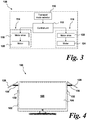
- the transportation arrangement 108 comprises a transport mode selector 110, a control unit 112, a protection arrangement 114 to protect the display panel 106 from damage during transportation, and a cable release arrangement 116 operable to decouple any connected cables or connectors from the display device 100 prior to removal.
- Each of the protection and cable release arrangements 114, 116 comprises a respective motor drive 118, 120 and motor 122, 124.
- the transportation arrangement 108 has two modes of operation, a first, in-use mode (i.e. when the display device is in use, for example when a user is watching television) in which the protection arrangement 114 and cable release arrangement 116 are not activated, and a second, transportation mode in which the protection arrangement 110 and cable release arrangement 112 are activated.
- the second, transportation mode may be activated electronically through the transport mode selector 110. This may comprise, for example, the pressing of a button by the user on either the display device 100 itself, a button on a remote control (not shown) or selection of a menu item or icon on an on screen display (OSD) of the display device 100.
- This may comprise, for example, the pressing of a button by the user on either the display device 100 itself, a button on a remote control (not shown) or selection of a menu item or icon on an on screen display (OSD) of the display device 100.
- OSD on screen display
- control unit 112 is operable to send a control command to one or both of the protection arrangement 114 and cable release arrangement 116 to activate these arrangements.
- the protection arrangement 114 will be described first.
- the protection arrangement 114 is activated when the transport mode is selected by the user using the transport mode selector 110.
- the protection arrangement 114 is arranged to deploy mechanical protection elements to assist in protecting the display panel 106 from damage during removal, transport and installation of the display device 100.
- the protection arrangement 114 comprises movable mechanical elements to act as physical barriers to shocks, impacts and to provide local strengthening for the display device 100.
- the protection arrangement 114 comprises movable mechanical projections 126 which are movable between a first, stored position (as shown in Figure 2 ) and a second, extended position (as shown in Figures 4 to 8 ).
- the mechanical projections 126 lie flush with the housing 102 and form part of the external surface of the housing 102. In other words, the mechanical projections 126 form part of the sides of the bezel of the housing 102 and are visually unobtrusive and may be, effectively, invisible to the user.
- the mechanical projections 126 are extended to project from the sides of the display device 100 as shown in Figures 4 to 8 in order to protect the display device 100 and, in optional embodiments, to act as transportation handles for the display device.
- the protection arrangement comprises the mechanical projections 126.
- the mechanical projections 126 are pivoted about hinges 128 ( Figures 5 and 6 ) which are located on the upper corners of the housing 102 and bezel.
- the mechanical projections 126 comprise planar and rectangular elements which lie flush with the remainder of the housing 102 and bezel when not in use but pivot outwardly to extend parallel to the display panel 106.
- the mechanical projections 126 extend for, when in the stored position, approximately 40-50% of the height of the housing 102.
- the mechanical projections 126 may be snap-fitted as required.
- the protection arrangement 114 further comprises a mechanical activation system operable to automatically move the mechanical projections 126 from the first, stored, position to the second, extended position. As shown in Figures 4 to 8 , the protection arrangement 114 further comprises a pair of spring-loaded arms 130 arranged to extend and maintain the mechanical projections 126 in an extended position.
- the motor drive 118 and motor 120 are configured to operate a push pin 132 located in each side of the housing 102.
- the push pins 132 are, when activated, operable to push the mechanical projections 126 away from the sides of the housing 102 and allow the mechanical projections 126 to extend under the resilient bias of the spring-loaded arms 130.
- the push pins 132 are activated by operation of the motor 120 after a transport mode selector 110 command is received and processed by the control unit 112, which issues a command to the protection arrangement 114 to deploy the mechanical projections 126 or mechanical arms.
- the cable release arrangement comprises a mechanical configuration comprising ( Figure 9 ) a clamp 134 and spring pins 136.
- the motor drive 122 and motor 124 are operable to release the clamp 134 and the spring pins 136 will then open and pull away any connected cables or other external connections from the sockets 138 at the rear of the display device 100.
- These connectors may include, but are not limited to: HDMI connectors; S-Video connectors; DVI connectors; optical connectors; audio connectors; power connectors; and/or external aerial connectors.
- the control unit 112 issues a signal to the cable release arrangement 116 to activate the motor drive and motor 122, 124 and cause the clamp 134 to be opened and move away from the rear of the display device 100 causing all external connections to the display device 100 to be removed from the display device 100 prior to removal of the display device 100 for transportation and subsequent reinstallation.
- This arrangement and method is a convenient approach to enable a display device 100 to be removed from an installation without risk of damage.
- a user may attempt to lift the display device 100 in a situation where the external physical cable connections have not been removed. This may cause the display device 100 to fall to the floor, or the user to experience inconvenience during removal.
- the connected cables are swiftly and effectively removed prior to the user removing the display device.
- the cable release arrangement 116 will decouple any connected cables or connectors from the display device 100.
- the transport mode when the transport mode is activated, the external source connections connected to the TV will be safely disconnected without being damaged by the mechanical clamp and spring system.
- the protection arrangement 114 will be activated and will deploy the mechanical elements 126 (in embodiments, these elements may comprise snap-on mechanical arms) on the sides of the housing 102 of the display device 100 and the display device 100 will be ready for removal and carriage. After transport, the end user will be able to manually close the mechanical elements 126 which are held open by the resilient bias of the spring-loaded arms 130.
- the mechanical elements 126 may be deployed.
- the user may have previously disconnected the cable connectors and so automatic disconnection of these elements may not be required. This may be set by a user in, for example, an options menu.
- Step 200 Activate transport mode
- the transport mode is activated by the end user. This may be through any suitable means - for example, the user may select the transport mode from an option menu on the on-screen display (OST). Alternatively, the user may select the transport mode manually using a button either on a remote control (not shown) or a physical buttom on the housing 102 of the display device 100.
- OST on-screen display
- the user may select the transport mode manually using a button either on a remote control (not shown) or a physical buttom on the housing 102 of the display device 100.
- step 202 When the transport mode is activated, the method proceeds to step 202.
- Step 202 Activate protection arrangement
- control unit 112 When the transport mode is activated at step 200, the control unit 112 is operable to send a command to the protection arrangement 1142 activate The motor 118 fire the motor drive 118 and deploy the push pins 132 on each side of the housing 102.
- step 204 The method proceeds to step 204.
- Step 204 Deploy cable release arrangement
- control unit 112 When the transport mode is activated in step 200, the control unit 112 sends a control command to the cable release arrangement 116, including motor drive 122 and motor 124.
- the motor 124 When activated, the motor 124 releases the clamp 134 connected to the connections on the rear of the display device 100.
- the motor 124 has a shaft which is operable to push the clamp sections 134 apart, causing the spring pins 136 to bias the clamp portions away from the connected cables and release the cables from the display device 100.
- the motor 124 is operable to cause the connection cables to be released from the rear of the display device 100 for straightforward removal of the display device 100 from its installation location.
- this step may be optional.
- step 206 The method proceeds to step 206.
- Step 206 Transport display device
- step 204 Once the connections are released in step 204, and the mechanical elements 126 are deployed in step 202, the display device 100 is ready for removal and transportation. When the device has been transported to a new location, the method proceeds to step 208.
- Step 208 Reset transport mode and connections
- the mechanical arms 126 can be manually pushed back into the first, closed position where they lie flush with the housing 102 and bezels of the display device 100.
- the connections can be re-attached at the rear of the display device 100, and the clamp 134 and spring-loaded pins 136 reset to clamp the connections and maintain a secure connection to the connection cables and connectors at the rear of the display device 100.
- the arms may be mechanically retracted if desired, and the clamps maybe make it automatically engaged once the connections are established at the rear of the display device 100.
- the user can again activate the transport mode from either the OSD of the display device 100 or via a mechanical button as described above when it is again desired to move or relocate the display device 100.
- a display device 100 can be transported effectively with low risk of damage to the display panel 106. Therefore, narrower and weaker bezels and housing 102 can be provided, providing visual improvements and improved aesthetics for the user without increased risk of damage to the display panel 106.
- the mechanical elements 126 or arms are shown as extending away from the sides of the display device 100, this not need to be the case.
- the arms may extend laterally from within the display device 100 to an external position thereof in a sliding motion along an axis parallel to the planar display panel 106.
- the arms 126 may deploy from the upper or lower surfaces of the housing 102, or a plurality of arms may be provided on each side or upper or lower surface of the housing 102.
- the skilled person will be readily aware of variations which would fall within the scope of the present disclosure.
- the cable release arrangement 116 may take other suitable forms.
- a pivotable arm, or articulated arm may be used to pull the connections away from the rear of the display device 100 and release the connections and connectors.
Landscapes
- Engineering & Computer Science (AREA)
- Computer Hardware Design (AREA)
- Theoretical Computer Science (AREA)
- General Engineering & Computer Science (AREA)
- Human Computer Interaction (AREA)
- Physics & Mathematics (AREA)
- General Physics & Mathematics (AREA)
- Devices For Indicating Variable Information By Combining Individual Elements (AREA)
Abstract
In an embodiment, there is provided a display device comprising an outer housing and a display panel arranged within the outer housing, the display device further comprising one or more protection elements, wherein each protection element is automatically movable between a first position in which the protection element is stored during normal use of the display device and a second position in which the protection element extends from the outer housing to protect the display device during transportation in response to a user command.
Description
- The present invention relates to a protection arrangement for a display device. More particularly, the present invention relates to an integrated protection and transportation arrangement for a flat screen display panel to prevent damage during transit and relocation of the display device.
- Recently, there has been a drive towards ever smaller and thinner flat screen display devices. For example, in the field of LCD, LED and OLED flat screen televisions and monitors, it is desirable to reduce the width of the bezels surrounding the display panel. This makes the display device smaller for a given screen size, and makes the device more aesthetically pleasing for the user.
- However, the reduction in size of the bezel and support structure of a display device reduces the strength of this structure, potentially exposing the fragile display panel itself to increased stresses and strains when the display device is being moved, for example, during transportation, installation or removal prior to reinstallation elsewhere. Therefore, there is an increased risk that a display panel may be irreparably damaged during transportation.
- One solution to this issue is to provide a specialised carrying container for the display device where a display device is placed in a strengthened support structure to enable transportation of the display device. Examples of such packaging devices are disclosed in
US 2013/0277253 ,US 2008/0067096 andUS 2014/0097117 . - However, a drawback to these solutions is that the packaging devices require separate storage space when not in use, and it may be cumbersome and time-consuming to load the display device into the respective packaging device prior to transportation.
- Therefore, to date, known arrangements and methods suffer from the drawback that known transportation arrangements for protecting a display device are inconvenient and cumbersome.
- The present invention, in embodiments, addresses this issue.
- According to a first aspect of the present invention, there is provided a display device comprising an outer housing and a display panel arranged within the outer housing, the display device further comprising one or more protection elements, wherein each protection element is automatically movable between a first position in which the protection element is stored during normal use of the display device and a second position in which the protection element extends from the outer housing to protect the display device during transportation in response to a user command.
- In one embodiment, the or each protection element comprises a mechanical arm arranged to pivot away from a surface of the housing.
- In one embodiment, the or each protection element is biased from the first to the second position by means of a biasing arrangement.
- In one embodiment, the movement of the or each protection element is actuated by electronic means.
- In one embodiment, the movement of the or each protection device is actuated by a motor.
- In one embodiment, the protection element is configured to form a part of the outer housing when in the first position.
- In one embodiment, in the second position the or each protection element extends from the sides of the display device.
- In one embodiment, the display device further comprises a cable release arrangement having first and second positions, wherein in the first position the cable release arrangement is configured such that one or more cable connectors remain connected to the respective connector ports of the display device and in the second position the cable support arrangement is configured to release the cables from the display device, wherein the cable release arrangement is automatically movable from the respective first position to the respective second position in response to the user command.
- In one embodiment, the cable release arrangement comprises one or more clamps and/or one or more biasing arrangements.
- In one embodiment, the cable release arrangement is movable electronically.
- In one embodiment, the cable release arrangement is movable by means of a motor.
- According to a second aspect of the present invention, there is provided a method for protecting a display device during transportation, the display device comprising an outer housing and display panel arranged within the outer housing, method comprising the steps of: activating, in response to a user command, a transportation mode of the display device, and in response to said activation: automatically moving one or more protection elements of the display device from a first position in which the or each protection element is stored during normal use of the display device to a second position in which the protection element extends from the outer housing to protect the display device during transportation.
- In one embodiment, the method further comprises automatically moving a cable release arrangement from a first position in which the cable release arrangement is configured such that one or more cable connectors remain connected to the respective connector ports of the display device to a second position in which the cable support arrangement is configured to release the cables from the display device.
In one embodiment, the one or more protection elements are actuated electronically to move from the respective first position to the respective second position. - In one embodiment, once actuated, the or each protection element is biased from the first to the second position by means of a biasing arrangement.
- Embodiments of the present invention will now be described in detail with reference to the accompanying drawings, in which:
-
Figure 1 is a general view of an exemplary display device; -
Figure 2 is a schematic front view of a display device having a transportation arrangement according to embodiment of the present invention, where the transportation arrangement is shown in a first configuration; -
Figure 3 is a schematic feature block view of a transportation arrangement according to an embodiment; -
Figure 4 is a schematic front view of the display device ofFigure 2 showing the transportation arrangement in a second configuration; -
Figure 5 is an isometric view of the display device ofFigure 4 with the transportation arrangement in the second configuration; -
Figure 6 is a plan view of the display device shown inFigures 4 and5 ; -
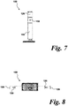
Figure 7 is a side view of the display device shown inFigures 4 to 6 ; -
Figure 8 is a bottom view of the display device shown inFigures 4 to 7 ; -
Figure 9 is a rear view of the display device ofFigures 2 to 8 ; and -
Figure 10 is a flow chart showing a method according to an embodiment of the present invention. -
Figure 1 shows anexemplary display device 10 in the form of a flat panel television. Thedisplay device 10 has anouter housing 12 supported by astand 14. Adisplay panel 16 is located within theouter housing 12. - In this example, the
display panel 16 comprises a Light Emitting Diode (LED) television display, where an array of LEDs are used to illuminate a Liquid Crystal Display (LCD) panel. However, this is not to be taken as limiting and other types of display may be used; for example, direct LED (D-LED) LCD displays, plasma displays, Organic Light Emitting Diode (OLED) displays, standard LCD panels or any other suitable display panel. The precise type of display panel used is not material to the invention, although in general the display panel will be a flat display panel. - As shown in
Figure 1 , theouter housing 12 comprises abezel 18 which supports, surrounds and protects thedisplay panel 16 in use. End users generally prefer narrower bezels and a smallerouter housing 12. However, this causes problems in terms of supporting thedisplay panel 16 and preventing thedisplay panel 16 from becoming damaged during removal from an installation location and subsequent transportation. The present invention addresses, in embodiments, this issue. -
Figure 2 shows adisplay device 100 according to an embodiment of the present invention. Thedisplay device 100 comprises ahousing 102, astand 104 and adisplay panel 106. - A
display device 100 further comprises atransportation arrangement 108. Thetransportation arrangement 108 is configured, in use, to enable safe removal and transportation of thedisplay device 100 and to minimise the risk of damage to thedisplay panel 106. - The
transportation arrangement 108 is shown schematically inFigure 3 . Thetransportation arrangement 108 comprises atransport mode selector 110, acontrol unit 112, aprotection arrangement 114 to protect thedisplay panel 106 from damage during transportation, and acable release arrangement 116 operable to decouple any connected cables or connectors from thedisplay device 100 prior to removal. - Each of the protection and
cable release arrangements respective motor drive motor - In embodiments, the
transportation arrangement 108 has two modes of operation, a first, in-use mode (i.e. when the display device is in use, for example when a user is watching television) in which theprotection arrangement 114 andcable release arrangement 116 are not activated, and a second, transportation mode in which theprotection arrangement 110 andcable release arrangement 112 are activated. - In embodiments, the second, transportation mode may be activated electronically through the
transport mode selector 110. This may comprise, for example, the pressing of a button by the user on either thedisplay device 100 itself, a button on a remote control (not shown) or selection of a menu item or icon on an on screen display (OSD) of thedisplay device 100. - Once the transport mode is selected by the
selector 110, thecontrol unit 112 is operable to send a control command to one or both of theprotection arrangement 114 andcable release arrangement 116 to activate these arrangements. - The
protection arrangement 114 will be described first. Theprotection arrangement 114 is activated when the transport mode is selected by the user using thetransport mode selector 110. Theprotection arrangement 114 is arranged to deploy mechanical protection elements to assist in protecting thedisplay panel 106 from damage during removal, transport and installation of thedisplay device 100. - In embodiments, the
protection arrangement 114 comprises movable mechanical elements to act as physical barriers to shocks, impacts and to provide local strengthening for thedisplay device 100. - In embodiments, the
protection arrangement 114 comprises movablemechanical projections 126 which are movable between a first, stored position (as shown inFigure 2 ) and a second, extended position (as shown inFigures 4 to 8 ). - When in the stored position (
Figure 2 ), themechanical projections 126 lie flush with thehousing 102 and form part of the external surface of thehousing 102. In other words, themechanical projections 126 form part of the sides of the bezel of thehousing 102 and are visually unobtrusive and may be, effectively, invisible to the user. - When the transport mode is activated, the
mechanical projections 126 are extended to project from the sides of thedisplay device 100 as shown inFigures 4 to 8 in order to protect thedisplay device 100 and, in optional embodiments, to act as transportation handles for the display device. - Turning to the
protection arrangement 114 in detail, with reference toFigures 4 to 8 , the protection arrangement comprises themechanical projections 126. Themechanical projections 126 are pivoted about hinges 128 (Figures 5 and 6 ) which are located on the upper corners of thehousing 102 and bezel. Themechanical projections 126 comprise planar and rectangular elements which lie flush with the remainder of thehousing 102 and bezel when not in use but pivot outwardly to extend parallel to thedisplay panel 106. Themechanical projections 126 extend for, when in the stored position, approximately 40-50% of the height of thehousing 102. In embodiments, themechanical projections 126 may be snap-fitted as required. - The
protection arrangement 114 further comprises a mechanical activation system operable to automatically move themechanical projections 126 from the first, stored, position to the second, extended position. As shown inFigures 4 to 8 , theprotection arrangement 114 further comprises a pair of spring-loadedarms 130 arranged to extend and maintain themechanical projections 126 in an extended position. - In addition, the
motor drive 118 andmotor 120 are configured to operate apush pin 132 located in each side of thehousing 102. The push pins 132 are, when activated, operable to push themechanical projections 126 away from the sides of thehousing 102 and allow themechanical projections 126 to extend under the resilient bias of the spring-loadedarms 130. - The push pins 132 are activated by operation of the
motor 120 after atransport mode selector 110 command is received and processed by thecontrol unit 112, which issues a command to theprotection arrangement 114 to deploy themechanical projections 126 or mechanical arms. - Turning now to the
cable release arrangement 116, with reference toFigure 9 , the cable release arrangement comprises a mechanical configuration comprising (Figure 9 ) aclamp 134 and spring pins 136. - In use, the
motor drive 122 andmotor 124 are operable to release theclamp 134 and the spring pins 136 will then open and pull away any connected cables or other external connections from thesockets 138 at the rear of thedisplay device 100. These connectors may include, but are not limited to: HDMI connectors; S-Video connectors; DVI connectors; optical connectors; audio connectors; power connectors; and/or external aerial connectors. - In other words, when the transport mode is activated through a user interaction with the
transport mode selector 110, thecontrol unit 112 issues a signal to thecable release arrangement 116 to activate the motor drive andmotor clamp 134 to be opened and move away from the rear of thedisplay device 100 causing all external connections to thedisplay device 100 to be removed from thedisplay device 100 prior to removal of thedisplay device 100 for transportation and subsequent reinstallation. - This arrangement and method is a convenient approach to enable a
display device 100 to be removed from an installation without risk of damage. For examples, in a conventional known display device, a user may attempt to lift thedisplay device 100 in a situation where the external physical cable connections have not been removed. This may cause thedisplay device 100 to fall to the floor, or the user to experience inconvenience during removal. - By the method of the present invention, when the user selects the transport mode from an options menu on the OSD of the
display device 100, or via a button on a remote control or on thehousing 102 of thedisplay device 100, the connected cables are swiftly and effectively removed prior to the user removing the display device. - This allows convenient removal of a display device without the risk of contacting or catching wires on elements which may cause damage to the
display device 100. In addition, in the deployment of themechanical protection arms 126 can assist in preventing damage to thedisplay panel 106 of thedisplay device 100. - In summary, activation of the second, transportation mode will cause two actions to occur. Firstly, the
cable release arrangement 116 will decouple any connected cables or connectors from thedisplay device 100. In other words, when the transport mode is activated, the external source connections connected to the TV will be safely disconnected without being damaged by the mechanical clamp and spring system. - At the same time, the
protection arrangement 114 will be activated and will deploy the mechanical elements 126 (in embodiments, these elements may comprise snap-on mechanical arms) on the sides of thehousing 102 of thedisplay device 100 and thedisplay device 100 will be ready for removal and carriage. After transport, the end user will be able to manually close themechanical elements 126 which are held open by the resilient bias of the spring-loadedarms 130. - However, it is also within the scope of the present disclosure for only the
mechanical elements 126 to deploy. For example, the user may have previously disconnected the cable connectors and so automatic disconnection of these elements may not be required. This may be set by a user in, for example, an options menu. - A method according to an embodiment of the invention will now be described with reference to
Figure 10 . - At
step 200, the transport mode is activated by the end user. This may be through any suitable means - for example, the user may select the transport mode from an option menu on the on-screen display (OST). Alternatively, the user may select the transport mode manually using a button either on a remote control (not shown) or a physical buttom on thehousing 102 of thedisplay device 100. - When the transport mode is activated, the method proceeds to step 202.
- When the transport mode is activated at
step 200, thecontrol unit 112 is operable to send a command to the protection arrangement 1142 activate Themotor 118 fire themotor drive 118 and deploy the push pins 132 on each side of thehousing 102. - This causes the
mechanic arms 126 to be deployed through the resilient bias of the spring-loadedarms 130. When the spring-loadedarms 130 are deployed, the risk of damage to thedisplay panel 106 is reduced. - The method proceeds to step 204.
- When the transport mode is activated in
step 200, thecontrol unit 112 sends a control command to thecable release arrangement 116, includingmotor drive 122 andmotor 124. - When activated, the
motor 124 releases theclamp 134 connected to the connections on the rear of thedisplay device 100. In other words, themotor 124 has a shaft which is operable to push theclamp sections 134 apart, causing the spring pins 136 to bias the clamp portions away from the connected cables and release the cables from thedisplay device 100. - In other words, when the
cable release arrangement 116 is activated, themotor 124 is operable to cause the connection cables to be released from the rear of thedisplay device 100 for straightforward removal of thedisplay device 100 from its installation location. - As noted above, this step may be optional.
- The method proceeds to step 206.
- Once the connections are released in
step 204, and themechanical elements 126 are deployed instep 202, thedisplay device 100 is ready for removal and transportation. When the device has been transported to a new location, the method proceeds to step 208. - As an optional step, the
mechanical arms 126 can be manually pushed back into the first, closed position where they lie flush with thehousing 102 and bezels of thedisplay device 100. In addition, the connections can be re-attached at the rear of thedisplay device 100, and theclamp 134 and spring-loadedpins 136 reset to clamp the connections and maintain a secure connection to the connection cables and connectors at the rear of thedisplay device 100. - However, this is an optional step, and may, in embodiments be carried out automatically by the
protection arrangement 114 and/orcable release arrangement 116. In other words, the arms may be mechanically retracted if desired, and the clamps maybe make it automatically engaged once the connections are established at the rear of thedisplay device 100. - Either way, once the respective connections and arms are reset, the user can again activate the transport mode from either the OSD of the
display device 100 or via a mechanical button as described above when it is again desired to move or relocate thedisplay device 100. - By providing such an arrangement, a
display device 100 can be transported effectively with low risk of damage to thedisplay panel 106. Therefore, narrower and weaker bezels andhousing 102 can be provided, providing visual improvements and improved aesthetics for the user without increased risk of damage to thedisplay panel 106. - Variations will be obvious to the skilled person. For example, whilst the
mechanical elements 126 or arms are shown as extending away from the sides of thedisplay device 100, this not need to be the case. For example, the arms may extend laterally from within thedisplay device 100 to an external position thereof in a sliding motion along an axis parallel to theplanar display panel 106. Alternatively, thearms 126 may deploy from the upper or lower surfaces of thehousing 102, or a plurality of arms may be provided on each side or upper or lower surface of thehousing 102. The skilled person will be readily aware of variations which would fall within the scope of the present disclosure. - In addition, the
cable release arrangement 116 may take other suitable forms. For example rather than a clamp and spring arrangement. For example, a pivotable arm, or articulated arm may be used to pull the connections away from the rear of thedisplay device 100 and release the connections and connectors. - In addition, whilst the above embodiments have been described with reference to the use of a motor and motor shaft or push pin, this need not be the case. For example the
mechanical elements 126 may be held in place through other interactions, for example electromagnetic or other connections which can be released electronically or automatically upon activation of the transport mode. - Embodiments of the present invention have been described with particular reference to the examples illustrated. While specific examples are shown in the drawings and are herein described in detail, it should be understood, however, that the drawings and detailed description are not intended to limit the invention to the particular form disclosed. It will be appreciated that variations and modifications may be made to the examples described within the scope of the present invention.
Claims (15)
- A display device comprising an outer housing and a display panel arranged within the outer housing, the display device further comprising one or more protection elements, wherein each protection element is automatically movable between a first position in which the protection element is stored during normal use of the display device and a second position in which the protection element extends from the outer housing to protect the display device during transportation in response to a user command.
- A display device according to claim 1, wherein the or each protection element comprises a mechanical arm arranged to pivot away from a surface of the housing.
- A display device according to claim 1 or 2, wherein the or each protection element is biased from the first to the second position by means of a biasing arrangement.
- A display device according to any one of the preceding claims, wherein the movement of the or each protection element is actuated by electronic means.
- A display device according to claim 4, wherein the movement of the or each protection device is actuated by a motor.
- A display device according to any one of the preceding claims, wherein the protection element is configured to form a part of the outer housing when in the first position.
- A display device according to any one of the preceding claims, wherein in the second position the or each protection element extends from the sides of the display device.
- A display device according to any one of the preceding claims, wherein the display device further comprises a cable release arrangement having first and second positions, wherein in the first position the cable release arrangement is configured such that one or more cable connectors remain connected to the respective connector ports of the display device and in the second position the cable support arrangement is configured to release the cables from the display device, wherein the cable release arrangement is automatically movable from the respective first position to the respective second position in response to the user command.
- A display device according to claim 8, wherein the cable release arrangement comprises one or more clamps and/or one or more biasing arrangements.
- A display device according to claim 8 or 9, wherein the cable release arrangement is movable electronically.
- A display device according to claim 8, 9 or 10, wherein the cable release arrangement is movable by means of a motor.
- A method for protecting a display device during transportation, the display device comprising an outer housing and display panel arranged within the outer housing, method comprising the steps of:a) activating, in response to a user command, a transportation mode of the display device, and in response to said activation:b) automatically moving one or more protection elements of the display device from a first position in which the or each protection element is stored during normal use of the display device to a second position in which the protection element extends from the outer housing to protect the display device during transportation.
- A method according to claim 12, further comprising:c) automatically moving a cable release arrangement from a first position in which the cable release arrangement is configured such that one or more cable connectors remain connected to the respective connector ports of the display device to a second position in which the cable support arrangement is configured to release the cables from the display device.
- A method according to claim 12 or 13, wherein the one or more protection elements are actuated electronically to move from the respective first position to the respective second position.
- A method according to claim 14, wherein, once actuated, the or each protection element is biased from the first to the second position by means of a biasing arrangement.
Priority Applications (1)
| Application Number | Priority Date | Filing Date | Title |
|---|---|---|---|
| EP18163798.4A EP3543822A1 (en) | 2018-03-23 | 2018-03-23 | A protection arrangement for a display device |
Applications Claiming Priority (1)
| Application Number | Priority Date | Filing Date | Title |
|---|---|---|---|
| EP18163798.4A EP3543822A1 (en) | 2018-03-23 | 2018-03-23 | A protection arrangement for a display device |
Publications (1)
| Publication Number | Publication Date |
|---|---|
| EP3543822A1 true EP3543822A1 (en) | 2019-09-25 |
Family
ID=61768147
Family Applications (1)
| Application Number | Title | Priority Date | Filing Date |
|---|---|---|---|
| EP18163798.4A Withdrawn EP3543822A1 (en) | 2018-03-23 | 2018-03-23 | A protection arrangement for a display device |
Country Status (1)
| Country | Link |
|---|---|
| EP (1) | EP3543822A1 (en) |
Citations (6)
| Publication number | Priority date | Publication date | Assignee | Title |
|---|---|---|---|---|
| US7059182B1 (en) * | 2004-03-03 | 2006-06-13 | Gary Dean Ragner | Active impact protection system |
| US20080067096A1 (en) | 2006-09-19 | 2008-03-20 | Funai Electric Co., Ltd. | Plasma television packing structure and panel display device packing structure |
| US20090321199A1 (en) * | 2008-06-26 | 2009-12-31 | Hon Hai Precision Industry Co., Ltd. | Apparatus with protection mechanism |
| US20130277253A1 (en) | 2007-03-14 | 2013-10-24 | Bby Solutions, Inc. | Protective container for a flat screen monitor |
| US20140097117A1 (en) | 2012-01-17 | 2014-04-10 | Panasonic Corporation | Package device for thin display device |
| US20150301565A1 (en) * | 2014-04-18 | 2015-10-22 | Apple Inc. | Active screen protection for electronic device |
-
2018
- 2018-03-23 EP EP18163798.4A patent/EP3543822A1/en not_active Withdrawn
Patent Citations (6)
| Publication number | Priority date | Publication date | Assignee | Title |
|---|---|---|---|---|
| US7059182B1 (en) * | 2004-03-03 | 2006-06-13 | Gary Dean Ragner | Active impact protection system |
| US20080067096A1 (en) | 2006-09-19 | 2008-03-20 | Funai Electric Co., Ltd. | Plasma television packing structure and panel display device packing structure |
| US20130277253A1 (en) | 2007-03-14 | 2013-10-24 | Bby Solutions, Inc. | Protective container for a flat screen monitor |
| US20090321199A1 (en) * | 2008-06-26 | 2009-12-31 | Hon Hai Precision Industry Co., Ltd. | Apparatus with protection mechanism |
| US20140097117A1 (en) | 2012-01-17 | 2014-04-10 | Panasonic Corporation | Package device for thin display device |
| US20150301565A1 (en) * | 2014-04-18 | 2015-10-22 | Apple Inc. | Active screen protection for electronic device |
Similar Documents
| Publication | Publication Date | Title |
|---|---|---|
| CN1690789B (en) | Height adjustable stand with disengaging and locking parts for liquid crystal display | |
| KR102454387B1 (en) | Rollerable display device | |
| KR102055204B1 (en) | Display device including camera module | |
| EP3136714A1 (en) | Display device | |
| US10120226B2 (en) | Display device with simplified appearance structure | |
| US10402635B2 (en) | Electronic device having supporting component | |
| US11055052B2 (en) | Display apparatus forming wall display and controlling method thereof | |
| US20120212910A1 (en) | Locking device, electronic device, and locking method | |
| US20110203956A1 (en) | Multi-mode protective device for portable video players | |
| KR20180026944A (en) | Display apparatus | |
| KR101217123B1 (en) | Supporting device for display unit | |
| US20190202655A1 (en) | Cable retractor | |
| US10729025B1 (en) | Display device with lock cover structure | |
| KR102758867B1 (en) | Dispay apparatus and method for assembling the same | |
| CN108297005A (en) | Assembling and testing device and holder for assembling and testing device | |
| KR102369952B1 (en) | motherboard and display panel | |
| KR20100113196A (en) | Display apparatus | |
| EP2833345B1 (en) | Display conveying device | |
| US20030169564A1 (en) | Hideable accessory platform | |
| KR100754330B1 (en) | Stand structure of the display device | |
| KR100778217B1 (en) | Wall-mount stand for video display. | |
| KR101387505B1 (en) | Display apparatus | |
| CN101039555A (en) | Folding electronic apparatus | |
| KR200236190Y1 (en) | Case of folder type multi display device | |
| KR102274282B1 (en) | Connector |
Legal Events
| Date | Code | Title | Description |
|---|---|---|---|
| PUAI | Public reference made under article 153(3) epc to a published international application that has entered the european phase |
Free format text: ORIGINAL CODE: 0009012 |
|
| AK | Designated contracting states |
Kind code of ref document: A1 Designated state(s): AL AT BE BG CH CY CZ DE DK EE ES FI FR GB GR HR HU IE IS IT LI LT LU LV MC MK MT NL NO PL PT RO RS SE SI SK SM TR |
|
| AX | Request for extension of the european patent |
Extension state: BA ME |
|
| STAA | Information on the status of an ep patent application or granted ep patent |
Free format text: STATUS: THE APPLICATION IS DEEMED TO BE WITHDRAWN |
|
| 18D | Application deemed to be withdrawn |
Effective date: 20200603 |