EP3543759A1 - Variable magnification optical system, optical device, imaging device, and manufacturing method of variable magnification optical system - Google Patents
Variable magnification optical system, optical device, imaging device, and manufacturing method of variable magnification optical system Download PDFInfo
- Publication number
- EP3543759A1 EP3543759A1 EP16921831.0A EP16921831A EP3543759A1 EP 3543759 A1 EP3543759 A1 EP 3543759A1 EP 16921831 A EP16921831 A EP 16921831A EP 3543759 A1 EP3543759 A1 EP 3543759A1
- Authority
- EP
- European Patent Office
- Prior art keywords
- lens group
- lens
- optical system
- zoom optical
- refractive power
- Prior art date
- Legal status (The legal status is an assumption and is not a legal conclusion. Google has not performed a legal analysis and makes no representation as to the accuracy of the status listed.)
- Pending
Links
- 230000003287 optical effect Effects 0.000 title claims abstract description 332
- 238000003384 imaging method Methods 0.000 title claims description 33
- 238000004519 manufacturing process Methods 0.000 title claims description 8
- 230000014509 gene expression Effects 0.000 claims description 167
- 230000005499 meniscus Effects 0.000 claims description 111
- 238000006073 displacement reaction Methods 0.000 claims description 17
- 238000000034 method Methods 0.000 claims description 8
- 230000004075 alteration Effects 0.000 description 236
- 230000000694 effects Effects 0.000 description 62
- 230000006870 function Effects 0.000 description 30
- 206010073261 Ovarian theca cell tumour Diseases 0.000 description 7
- 230000015556 catabolic process Effects 0.000 description 7
- 238000006731 degradation reaction Methods 0.000 description 7
- 208000001644 thecoma Diseases 0.000 description 7
- 230000007423 decrease Effects 0.000 description 6
- 206010010071 Coma Diseases 0.000 description 5
- 230000002349 favourable effect Effects 0.000 description 3
- 239000011521 glass Substances 0.000 description 3
- 201000009310 astigmatism Diseases 0.000 description 2
- 239000000463 material Substances 0.000 description 2
- 239000002131 composite material Substances 0.000 description 1
- 238000009826 distribution Methods 0.000 description 1
- 230000011514 reflex Effects 0.000 description 1
- 239000011347 resin Substances 0.000 description 1
- 229920005989 resin Polymers 0.000 description 1
Images





































Classifications
-
- G—PHYSICS
- G02—OPTICS
- G02B—OPTICAL ELEMENTS, SYSTEMS OR APPARATUS
- G02B15/00—Optical objectives with means for varying the magnification
- G02B15/14—Optical objectives with means for varying the magnification by axial movement of one or more lenses or groups of lenses relative to the image plane for continuously varying the equivalent focal length of the objective
- G02B15/145—Optical objectives with means for varying the magnification by axial movement of one or more lenses or groups of lenses relative to the image plane for continuously varying the equivalent focal length of the objective having five groups only
- G02B15/1451—Optical objectives with means for varying the magnification by axial movement of one or more lenses or groups of lenses relative to the image plane for continuously varying the equivalent focal length of the objective having five groups only the first group being positive
-
- G—PHYSICS
- G02—OPTICS
- G02B—OPTICAL ELEMENTS, SYSTEMS OR APPARATUS
- G02B15/00—Optical objectives with means for varying the magnification
- G02B15/14—Optical objectives with means for varying the magnification by axial movement of one or more lenses or groups of lenses relative to the image plane for continuously varying the equivalent focal length of the objective
- G02B15/145—Optical objectives with means for varying the magnification by axial movement of one or more lenses or groups of lenses relative to the image plane for continuously varying the equivalent focal length of the objective having five groups only
- G02B15/1451—Optical objectives with means for varying the magnification by axial movement of one or more lenses or groups of lenses relative to the image plane for continuously varying the equivalent focal length of the objective having five groups only the first group being positive
- G02B15/145105—Optical objectives with means for varying the magnification by axial movement of one or more lenses or groups of lenses relative to the image plane for continuously varying the equivalent focal length of the objective having five groups only the first group being positive arranged +-+--
-
- G—PHYSICS
- G02—OPTICS
- G02B—OPTICAL ELEMENTS, SYSTEMS OR APPARATUS
- G02B15/00—Optical objectives with means for varying the magnification
- G02B15/14—Optical objectives with means for varying the magnification by axial movement of one or more lenses or groups of lenses relative to the image plane for continuously varying the equivalent focal length of the objective
- G02B15/145—Optical objectives with means for varying the magnification by axial movement of one or more lenses or groups of lenses relative to the image plane for continuously varying the equivalent focal length of the objective having five groups only
- G02B15/1451—Optical objectives with means for varying the magnification by axial movement of one or more lenses or groups of lenses relative to the image plane for continuously varying the equivalent focal length of the objective having five groups only the first group being positive
- G02B15/145121—Optical objectives with means for varying the magnification by axial movement of one or more lenses or groups of lenses relative to the image plane for continuously varying the equivalent focal length of the objective having five groups only the first group being positive arranged +-+-+
-
- G—PHYSICS
- G02—OPTICS
- G02B—OPTICAL ELEMENTS, SYSTEMS OR APPARATUS
- G02B15/00—Optical objectives with means for varying the magnification
- G02B15/14—Optical objectives with means for varying the magnification by axial movement of one or more lenses or groups of lenses relative to the image plane for continuously varying the equivalent focal length of the objective
- G02B15/145—Optical objectives with means for varying the magnification by axial movement of one or more lenses or groups of lenses relative to the image plane for continuously varying the equivalent focal length of the objective having five groups only
- G02B15/1451—Optical objectives with means for varying the magnification by axial movement of one or more lenses or groups of lenses relative to the image plane for continuously varying the equivalent focal length of the objective having five groups only the first group being positive
- G02B15/145125—Optical objectives with means for varying the magnification by axial movement of one or more lenses or groups of lenses relative to the image plane for continuously varying the equivalent focal length of the objective having five groups only the first group being positive arranged +--++
-
- G—PHYSICS
- G02—OPTICS
- G02B—OPTICAL ELEMENTS, SYSTEMS OR APPARATUS
- G02B15/00—Optical objectives with means for varying the magnification
- G02B15/14—Optical objectives with means for varying the magnification by axial movement of one or more lenses or groups of lenses relative to the image plane for continuously varying the equivalent focal length of the objective
- G02B15/16—Optical objectives with means for varying the magnification by axial movement of one or more lenses or groups of lenses relative to the image plane for continuously varying the equivalent focal length of the objective with interdependent non-linearly related movements between one lens or lens group, and another lens or lens group
- G02B15/163—Optical objectives with means for varying the magnification by axial movement of one or more lenses or groups of lenses relative to the image plane for continuously varying the equivalent focal length of the objective with interdependent non-linearly related movements between one lens or lens group, and another lens or lens group having a first movable lens or lens group and a second movable lens or lens group, both in front of a fixed lens or lens group
- G02B15/167—Optical objectives with means for varying the magnification by axial movement of one or more lenses or groups of lenses relative to the image plane for continuously varying the equivalent focal length of the objective with interdependent non-linearly related movements between one lens or lens group, and another lens or lens group having a first movable lens or lens group and a second movable lens or lens group, both in front of a fixed lens or lens group having an additional fixed front lens or group of lenses
- G02B15/173—Optical objectives with means for varying the magnification by axial movement of one or more lenses or groups of lenses relative to the image plane for continuously varying the equivalent focal length of the objective with interdependent non-linearly related movements between one lens or lens group, and another lens or lens group having a first movable lens or lens group and a second movable lens or lens group, both in front of a fixed lens or lens group having an additional fixed front lens or group of lenses arranged +-+
-
- G—PHYSICS
- G02—OPTICS
- G02B—OPTICAL ELEMENTS, SYSTEMS OR APPARATUS
- G02B15/00—Optical objectives with means for varying the magnification
- G02B15/14—Optical objectives with means for varying the magnification by axial movement of one or more lenses or groups of lenses relative to the image plane for continuously varying the equivalent focal length of the objective
- G02B15/16—Optical objectives with means for varying the magnification by axial movement of one or more lenses or groups of lenses relative to the image plane for continuously varying the equivalent focal length of the objective with interdependent non-linearly related movements between one lens or lens group, and another lens or lens group
- G02B15/20—Optical objectives with means for varying the magnification by axial movement of one or more lenses or groups of lenses relative to the image plane for continuously varying the equivalent focal length of the objective with interdependent non-linearly related movements between one lens or lens group, and another lens or lens group having an additional movable lens or lens group for varying the objective focal length
-
- G—PHYSICS
- G02—OPTICS
- G02B—OPTICAL ELEMENTS, SYSTEMS OR APPARATUS
- G02B9/00—Optical objectives characterised both by the number of the components and their arrangements according to their sign, i.e. + or -
- G02B9/60—Optical objectives characterised both by the number of the components and their arrangements according to their sign, i.e. + or - having five components only
-
- G—PHYSICS
- G02—OPTICS
- G02B—OPTICAL ELEMENTS, SYSTEMS OR APPARATUS
- G02B15/00—Optical objectives with means for varying the magnification
- G02B15/14—Optical objectives with means for varying the magnification by axial movement of one or more lenses or groups of lenses relative to the image plane for continuously varying the equivalent focal length of the objective
- G02B15/146—Optical objectives with means for varying the magnification by axial movement of one or more lenses or groups of lenses relative to the image plane for continuously varying the equivalent focal length of the objective having more than five groups
-
- G—PHYSICS
- G02—OPTICS
- G02B—OPTICAL ELEMENTS, SYSTEMS OR APPARATUS
- G02B27/00—Optical systems or apparatus not provided for by any of the groups G02B1/00 - G02B26/00, G02B30/00
- G02B27/64—Imaging systems using optical elements for stabilisation of the lateral and angular position of the image
- G02B27/646—Imaging systems using optical elements for stabilisation of the lateral and angular position of the image compensating for small deviations, e.g. due to vibration or shake
-
- G—PHYSICS
- G02—OPTICS
- G02B—OPTICAL ELEMENTS, SYSTEMS OR APPARATUS
- G02B9/00—Optical objectives characterised both by the number of the components and their arrangements according to their sign, i.e. + or -
- G02B9/62—Optical objectives characterised both by the number of the components and their arrangements according to their sign, i.e. + or - having six components only
-
- G—PHYSICS
- G02—OPTICS
- G02B—OPTICAL ELEMENTS, SYSTEMS OR APPARATUS
- G02B9/00—Optical objectives characterised both by the number of the components and their arrangements according to their sign, i.e. + or -
- G02B9/64—Optical objectives characterised both by the number of the components and their arrangements according to their sign, i.e. + or - having more than six components
Definitions
- the present invention relates to a zoom optical system, an optical apparatus and an imaging apparatus including the same, and a method for manufacturing the zoom optical system.
- Patent literature 1 Japanese Laid-Open Patent Publication No. H4-293007(A )
- a zoom optical system comprises, in order from an object: a front lens group having a positive refractive power; an M1 lens group having a negative refractive power; an M2 lens group having a positive refractive power; an RN lens group having a negative refractive power; and a subsequent lens group, wherein upon zooming, a distance between the front lens group and the M1 lens group changes, a distance between the M1 lens group and the M2 lens group changes, and a distance between the M2 lens group and the RN lens group changes, and upon focusing from an infinite distant object to a short distant object, the RN lens group moves.
- An optical apparatus comprises the zoom optical system.
- An imaging apparatus comprises: the zoom optical system; and an imaging unit that takes an image formed by the zoom optical system.
- a method for manufacturing a zoom optical system comprising, in order from an object, a front lens group having a positive refractive power, an M1 lens group having a negative refractive power, an M2 lens group having a positive refractive power, an RN lens group having a negative refractive power, and a subsequent lens group, comprises achieving an arrangement where upon zooming, a distance between the front lens group and the M1 lens group changes, a distance between the M1 lens group and the M2 lens group changes, and a distance between the M2 lens group and the RN lens group changes, wherein upon focusing from an infinite distant object to a short distant object, the RN lens group moves, the subsequent lens group comprises, in order from the object, a lens having a negative refractive power and a lens having a positive refractive power, and a following conditional expression is satisfied, 0.70 ⁇ ⁇ fN / fP ⁇ 2.00 where
- a zoom optical system ZL(1) as an example of a zoom optical system (zoom lens) ZL comprises, in order from an object: a front lens group GFS having a positive refractive power; an M1 lens group GM1 having a negative refractive power; an M2 lens group GM2 having a positive refractive power; an RN lens group GRN having a negative refractive power; and a subsequent lens group GRS, wherein upon zooming, a distance between the front lens group GFS and the M1 lens group GM1 changes, a distance between the M1 lens group GM1 and the M2 lens group GM2 changes, and a distance between the M2 lens group GM2 and the RN lens group GRN changes, and upon focusing from an infinite distant object to a short distant object, the RN lens group GRN moves.
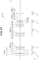
- the zoom optical system ZL may be a zoom optical system ZL(2) shown in FIG. 6 , a zoom optical system ZL(3) shown in FIG. 11 , a zoom optical system ZL(4) shown in FIG. 16 , a zoom optical system ZL(5) shown in FIG. 21 , a zoom optical system ZL(6) shown in FIG. 26 , a zoom optical system ZL(7) shown in FIG. 31 , a zoom optical system ZL(8) shown in FIG. 36 , a zoom optical system ZL(9) shown in FIG. 41 , a zoom optical system ZL(10) shown in FIG. 46 , a zoom optical system ZL(11) shown in FIG. 51 , a zoom optical system ZL(12) shown in FIG. 54 , or a zoom optical system ZL(13) shown in FIG. 57 .
- the zoom optical system of this embodiment includes at least five lens groups, and changes the distances between lens groups upon zooming from the wide-angle end state to the telephoto end state, thereby allowing favorable aberration correction upon zooming to be facilitated. Focusing with the RN lens group GRN can reduce the size and weight of the lens group for zooming.
- the optical apparatus, the imaging apparatus, and the method for manufacturing the zoom optical system according to this embodiment can also achieve analogous advantageous effects.
- the subsequent lens group GRS may comprise, in order from the object: a lens having a negative refractive power; and a lens having a positive refractive power. Accordingly, various aberrations including the coma aberration can be effectively corrected.
- conditional expression (1) described above defines the ratio of the focal length of the lens that is nearer to the image in the subsequent lens group GRS and has the strongest negative refractive power to the focal length of the lens that is nearer to the image in the subsequent lens group GRS and has the strongest positive refractive power.
- the refractive power of the lens that is nearer to the image in the focusing lens group and has a positive refractive power becomes strong, and the coma aberration occurs excessively.
- Setting of the upper limit value of the conditional expression (1) to 1.90 can more securely achieve the advantageous effects of this embodiment.
- the refractive power of the lens that is nearer to the image in the focusing lens group and has a negative refractive power becomes strong, and the coma aberration is excessively corrected.
- Setting of the lower limit value of the conditional expression (1) to 0.80 can more securely achieve the advantageous effects of this embodiment.
- the front lens group GFS moves toward the object. Accordingly, the entire length of the lens at the wide-angle end state can be reduced, which facilitates reduction in the size of the zoom optical system.
- the RN lens group GRN comprises: at least one lens having a positive refractive power; and at least one lens having a negative refractive power.
- the zoom optical system satisfies a following conditional expression (2), 0.15 ⁇ ⁇ fTM 1 / f 1 ⁇ 0.35
- the conditional expression (2) defines the ratio of the focal length of the M1 lens group GM1 to the focal length of the front lens group GFS in the telephoto end state.
- the refractive power of the front lens group GFS becomes strong, and it is difficult to correct various aberrations including the spherical aberration upon zooming from the wide-angle end to the telephoto end.
- Setting of the upper limit value of the conditional expression (2) to 0.33 can more securely achieve the advantageous effects of this embodiment.
- the refractive power of the M1 lens group GM1 becomes strong, and it is difficult to suppress variation in various aberrations including the spherical aberration upon zooming from the wide-angle end to the telephoto end.
- Setting of the lower limit value of the conditional expression (2) to 0.16 can more securely achieve the advantageous effects of this embodiment.
- the zoom optical system satisfies a following conditional expression (3), 0.20 ⁇ fTM 2 / f 1 ⁇ 0.40 where
- the conditional expression (3) defines the ratio of the focal length of the M2 lens group GM2 to the focal length of the front lens group GFS in the telephoto end state.
- the refractive power of the front lens group GFS becomes strong, and it is difficult to correct various aberrations including the spherical aberration upon zooming from the wide-angle end to the telephoto end.
- Setting of the upper limit value of the conditional expression (3) to 0.37 can more securely achieve the advantageous effects of this embodiment.
- the refractive power of the M2 lens group GM2 becomes strong, and it is difficult to suppress variation in various aberrations including the spherical aberration upon zooming from the wide-angle end to the telephoto end.
- Setting of the lower limit value of the conditional expression (3) to 0.22 can more securely achieve the advantageous effects of this embodiment.
- the system further comprises a negative meniscus lens that has a concave surface facing the object, and is adjacent to an image side of the RN lens group GRN. Accordingly, various aberrations including the coma aberration can be effectively corrected.
- the zoom optical system satisfies a following conditional expression (4), 1.80 ⁇ f 1 / fw ⁇ 3.50
- the conditional expression (4) defines the ratio of the focal length of the front lens group GFS to the focal length of the zoom optical system in the wide-angle end state.
- the refractive power of the front lens group GFS becomes weak, and the size of lens barrel increases.
- Setting of the upper limit value of the conditional expression (4) to 3.30 can more securely achieve the advantageous effects of this embodiment.
- the refractive power of the front lens group GFS becomes strong, and it is difficult to correct various aberrations including the spherical aberration upon zooming from the wide-angle end to the telephoto end.
- Setting of the lower limit value of the conditional expression (4) to 1.90 can more securely achieve the advantageous effects of this embodiment.
- the zoom optical system satisfies a following conditional expression (5), 3.70 ⁇ f 1 / ⁇ fTM 1 ⁇ 5.00
- the conditional expression (5) defines the ratio of the focal length of the front lens group GFS to the focal length of the M1 lens group GM1.
- the refractive power of the M1 lens group GM1 becomes strong, and it is difficult to suppress variation in various aberrations including the spherical aberration upon zooming from the wide-angle end to the telephoto end.
- Setting of the upper limit value of the conditional expression (5) to 4.90 can more securely achieve the advantageous effects of this embodiment.
- the refractive power of the front lens group GFS becomes strong, and it is difficult to correct various aberrations including the spherical aberration upon zooming from the wide-angle end to the telephoto end.
- Setting of the lower limit value of the conditional expression (5) to 3.90 can more securely achieve the advantageous effects of this embodiment.
- the zoom optical system satisfies a following conditional expression (6), 3.20 ⁇ f 1 / fTM 2 ⁇ 5.00 where
- the conditional expression (6) defines the ratio of the focal length of the front lens group GFS to the focal length of the M2 lens group GM2.
- the refractive power of the M2 lens group GM2 becomes strong, and it is difficult to suppress variation in various aberrations including the spherical aberration upon zooming from the wide-angle end to the telephoto end.
- Setting of the upper limit value of the conditional expression (6) to 4.80 can more securely achieve the advantageous effects of this embodiment.
- the refractive power of the front lens group GFS becomes strong, and it is difficult to correct various aberrations including the spherical aberration upon zooming from the wide-angle end to the telephoto end.
- Setting of the lower limit value of the conditional expression (6) to 3.40 can more securely achieve the advantageous effects of this embodiment.
- a lens group nearest to the object in the M1 lens group GM1 is fixed with respect to an image surface. Accordingly, degradation in performance due to manufacturing errors is suppressed, which can secure mass-productivity.
- the M2 lens group GM2 comprises a vibration-proof lens group movable in a direction orthogonal to an optical axis to correct an imaging position displacement due to a camera shake or the like.
- Such arrangement of the vibration-proof lens group in the M2 lens group GM2 can effectively suppress degradation in performance upon blur correction.
- the vibration-proof lens group consists of, in order from the object: a lens having a negative refractive power; and a lens having a positive refractive power. Accordingly, degradation in performance upon blur correction can be effectively suppressed.
- the zoom optical system satisfies a following conditional expression (7), 1.00 ⁇ nvrN / nvrP ⁇ 1.25 where
- the conditional expression (7) defines the ratio of the refractive index of the lens that is in the vibration-proof lens group provided in the M2 lens group GM2 and has a negative refractive power to the refractive index of the lens that is in the vibration-proof lens group and has a positive refractive power.
- the refractive index of the lens that is in the vibration-proof lens group and has a positive refractive power decreases, the decentering coma aberration caused upon blur correction excessively occurs, and it becomes difficult to correct the aberration.
- Setting of the upper limit value of the conditional expression (7) to 1.22 can more securely achieve the advantageous effects of this embodiment.
- the refractive index of the lens that is in the vibration-proof lens group and has a negative refractive power is appropriate, and the decentering coma aberration upon blur correction is favorably corrected, which is preferable.
- Setting of the lower limit value of the conditional expression (7) to 1.03 can more securely achieve the advantageous effects of this embodiment.
- the lower limit value of the conditional expression (7) be 1.05.
- the zoom optical system satisfies a following conditional expression (8), 0.30 ⁇ ⁇ ⁇ vrN / ⁇ ⁇ vrP ⁇ 0.90 where
- the conditional expression (8) defines the ratio of the Abbe number of the lens that is in the vibration-proof lens group and has a negative refractive power to the Abbe number of the lens that is in the vibration-proof lens group and has a positive refractive power.
- the corresponding value of the conditional expression (8) is in this range, the Abbe number of the lens that is in the vibration-proof lens group and has a positive refractive power is appropriate, and the chromatic aberration caused upon blur correction is favorably corrected, which is preferable.
- Setting of the upper limit value of the conditional expression (8) to 0.85 can more securely achieve the advantageous effects of this embodiment.
- the upper limit value of the conditional expression (8) be 0.80.
- the lower limit value of the conditional expression (8) can more securely achieve the advantageous effects of this embodiment.
- the lower limit value of the conditional expression (8) be 0.40.
- the M1 lens group GM1 also comprises a vibration-proof lens group movable in a direction orthogonal to an optical axis to correct an imaging position displacement due to a camera shake or the like.
- the vibration-proof lens group consists of, in order from the object: a lens having a negative refractive power; and a lens having a positive refractive power.
- the zoom optical system satisfies a following conditional expression (9), 0.80 ⁇ nvrN / nvrP ⁇ 1.00 where
- conditional expression (9) defines the ratio of the refractive index of the lens that is in the vibration-proof lens group provided in the M1 lens group GM1 and has a negative refractive power to the refractive index of the lens that is in the vibration-proof lens group provided in the M1 lens group GM1 and has a positive refractive power.
- the refractive index of the lens that is in the vibration-proof lens group provided in the M1 lens group GM1 and has a positive refractive power decreases, and it becomes difficult to correct the decentering coma aberration caused upon blur correction.
- Setting of the upper limit value of the conditional expression (9) to 0.98 can more securely achieve the advantageous effects of this embodiment.
- the refractive index of the lens that is in the vibration-proof lens group provided in the M1 lens group GM1 and has a negative refractive power decreases, and it becomes difficult to correct the decentering coma aberration caused upon blur correction.
- Setting of the lower limit value of the conditional expression (9) to 0.82 can more securely achieve the advantageous effects of this embodiment.
- the zoom optical system satisfies a following conditional expression (10), 1.20 ⁇ ⁇ ⁇ vrN / ⁇ ⁇ vrP ⁇ 2.40 where
- the conditional expression (10) defines the ratio of the Abbe number of the lens that is in the vibration-proof lens group provided in the M1 lens group GM1 and has a negative refractive power to the Abbe number of the lens that is in the vibration-proof lens group provided in the M1 lens group GM1 and has a positive refractive power.
- the Abbe number of the lens that is in the vibration-proof lens group provided in the M1 lens group GM1 and has a positive refractive power significantly decreases. Accordingly, it becomes difficult to correct the chromatic aberration caused upon blur correction.
- Setting of the upper limit value of the conditional expression (10) to 2.30 can more securely achieve the advantageous effects of this embodiment. To further secure the advantageous effects of this embodiment, it is preferable to set the upper limit value of the conditional expression (10) to 2.20.
- the Abbe number of the lens that is in the vibration-proof lens group provided in the M1 lens group GM1 and has a negative refractive power significantly decreases. Accordingly, it becomes difficult to correct the chromatic aberration caused upon blur correction.
- Setting of the lower limit value of the conditional expression (10) to 1.30 can more securely achieve the advantageous effects of this embodiment. To further secure the advantageous effects of this embodiment, it is preferable to set the lower limit value of the conditional expression (10) to 1.40.
- the subsequent lens group GRS comprises a lens having a positive refractive power. Accordingly, various aberrations including the coma aberration can be effectively corrected.
- the zoom optical system satisfies a following conditional expression (2), 0.15 ⁇ ⁇ fTM 1 / f 1 ⁇ 0.35
- conditional expression (2) is the same as described above.
- the details are as described above.
- the refractive power of the front lens group GFS becomes strong, and it is difficult to correct various aberrations including the spherical aberration upon zooming from the wide-angle end to the telephoto end.
- Setting of the upper limit value of the conditional expression (2) to 0.33 can more securely achieve the advantageous effects of this embodiment.
- the refractive power of the M1 lens group GM1 becomes strong, and it is difficult to suppress variation in various aberrations including the spherical aberration upon zooming from the wide-angle end to the telephoto end.
- Setting of the lower limit value of the conditional expression (2) to 0.16 can more securely achieve the advantageous effects of this embodiment.
- the zoom optical system satisfies a following conditional expression (3), 0.20 ⁇ fTM 2 / f 1 ⁇ 0.40
- conditional expression (3) is the same as described above. The details are as described above.
- the refractive power of the front lens group GFS becomes strong, and it is difficult to correct various aberrations including the spherical aberration upon zooming from the wide-angle end to the telephoto end.
- Setting of the upper limit value of the conditional expression (3) to 0.37 can more securely achieve the advantageous effects of this embodiment.
- the refractive power of the M2 lens group GM2 becomes strong, and it is difficult to suppress variation in various aberrations including the spherical aberration upon zooming from the wide-angle end to the telephoto end.
- Setting of the lower limit value of the conditional expression (3) to 0.22 can more securely achieve the advantageous effects of this embodiment.
- the zoom optical system satisfies a following conditional expression (4), 1.80 ⁇ f 1 / fw ⁇ 3.50
- conditional expression (4) is the same as described above.
- the details are as described above.
- the refractive power of the front lens group GFS becomes weak, and the size of lens barrel increases.
- Setting of the upper limit value of the conditional expression (4) to 3.30 can more securely achieve the advantageous effects of this embodiment.
- the refractive power of the front lens group GFS becomes strong, and it is difficult to correct various aberrations including the spherical aberration upon zooming from the wide-angle end to the telephoto end.
- Setting of the lower limit value of the conditional expression (4) to 1.90 can more securely achieve the advantageous effects of this embodiment.
- the zoom optical system satisfies a following conditional expression (5), 3.70 ⁇ f 1 / ⁇ fTM 1 ⁇ 5.00
- conditional expression (5) is the same as described above.
- the details are as described above.
- the refractive power of the M1 lens group GM1 becomes strong, and it is difficult to suppress variation in various aberrations including the spherical aberration upon zooming from the wide-angle end to the telephoto end.
- Setting of the upper limit value of the conditional expression (5) to 4.90 can more securely achieve the advantageous effects of this embodiment.
- the refractive power of the front lens group GFS becomes strong, and it is difficult to correct various aberrations including the spherical aberration upon zooming from the wide-angle end to the telephoto end.
- Setting of the lower limit value of the conditional expression (5) to 3.90 can more securely achieve the advantageous effects of this embodiment.
- the zoom optical system satisfies a following conditional expression (6), 3.20 ⁇ f 1 / fTM 2 ⁇ 5.00
- conditional expression (6) is the same as described above.
- the details are as described above.
- the refractive power of the M2 lens group GM2 becomes strong, and it is difficult to suppress variation in various aberrations including the spherical aberration upon zooming from the wide-angle end to the telephoto end.
- Setting of the upper limit value of the conditional expression (6) to 4.80 can more securely achieve the advantageous effects of this embodiment.
- the refractive power of the front lens group GFS becomes strong, and it is difficult to correct various aberrations including the spherical aberration upon zooming from the wide-angle end to the telephoto end.
- Setting of the lower limit value of the conditional expression (6) to 3.40 can more securely achieve the advantageous effects of this embodiment.
- An optical apparatus and an imaging apparatus comprise the zoom optical system having the configuration described above.
- a camera (corresponding to the imaging apparatus of the invention of the present application) including the aforementioned zoom optical system ZL is described with reference to FIG. 60 .
- this camera 1 has a lens assembly configuration including a replaceable imaging lens 2.
- the zoom optical system having the configuration described above is provided in the imaging lens 2. That is, the imaging lens 2 corresponds to the optical apparatus of the invention of the present application.
- the camera 1 is a digital camera. Light from an object (subject), not shown, is collected by the imaging lens 2, and reaches an imaging element 3. Accordingly, the light from the subject is imaged by the imaging element 3, and recorded as a subject image in a memory, not shown.
- a photographer can take an image of the subject through the camera 1.
- this camera may be a mirrorless camera, or a single-lens reflex type camera including a quick return mirror.
- the camera 1 mounted with the zoom optical system ZL described above in the imaging lens 2 can achieve high-speed AF and silence during AF without increasing the size of the lens barrel by reducing the size and weight of the focusing lens group. Furthermore, variation of aberrations upon zooming from the wide-angle end state to the telephoto end state, and variation of aberrations upon focusing from an infinite distant object to a short distant object can be favorably suppressed, and a favorable optical performance can be achieved.
- step ST1 arrange, in order from an object, a front lens group GFS having a positive refractive power, an M1 lens group GM1 having a negative refractive power, an M2 lens group GM2 having a positive refractive power, an RN lens group GRN having a negative refractive power, and a subsequent lens group GRS (step ST1).
- step ST2 achieve a configuration such that upon zooming, a distance between the front lens group GFS and the M1 lens group GM1 changes, a distance between the M1 lens group GM1 and the M2 lens group GM2 changes, and a distance between the M2 lens group GM2 and the RN lens group GRN changes, (step ST2).
- the RN lens group GRN moves (step ST3), and configure the subsequent lens group GRS to include, in order from the object, a lens having a negative refractive power, and a lens having a positive refractive power (step ST4).
- step ST5 arrange each lens so as to satisfy a predetermined conditional expression
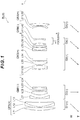
- FIGS. 1 , 6 , 11 , 16 , 21 , 26 , 31 , 36 , 41 , 46 , 51 , 54 and 57 are sectional views showing the configurations and refractive power distributions of the zoom optical systems ZL ⁇ ZL(1) to ZL(13) ⁇ according to first to thirteenth examples.
- the movement direction of each lens group along the optical axis during zooming from the wide-angle end state (W) to the telephoto end state (T) is indicated by a corresponding arrow.
- the movement direction during focusing the focusing group GRN from infinity to a short distant object is indicated by an arrow accompanied by characters "FOCUSING.”
- FIGS. 1 , 6 , 11 , 16 , 21 , 26 , 31 , 36 , 41 , 46 , 51 , 54 and 57 show each lens group by a combination of a symbol G and a numeral or alphabet(s), and show each lens by a combination of a symbol L and a numeral.
- the lens groups and the like are indicated using the combinations of symbols and numerals independently on an example-by-example basis. Accordingly, even though the same combinations of symbols and numerals are used among the examples, the combinations do not mean the same configurations.
- Tables 1 to 13 are hereinafter shown below. Tables 1 to 13 are tables representing various data in the first to thirteenth examples. In each example, d-line (wavelength 587.562 nm) and g-line (wavelength 435.835 nm) are selected as calculation targets of aberration characteristics.
- the surface number denotes the order of optical surfaces from the object along a light beam traveling direction
- R denotes the radius of curvature (a surface whose center of curvature is nearer to the image is assumed to have a positive value) of each optical surface
- D denotes the surface distance, which is the distance on the optical axis from each optical surface to the next optical surface (or the image surface)
- nd denotes the refractive index of the material of an optical element for the d-line
- vd denotes the Abbe number of the material of an optical element with reference to the d-line.
- the object surface denotes the surface of an object.
- " ⁇ " of the radius of curvature indicates a flat surface or an aperture.
- (Stop S) indicates an aperture stop S.
- the image surface indicates an image surface I.
- the description of the air refractive index nd 1.00000 is omitted.
- f denotes the focal length of the entire zoom lens
- FNO denotes the f-number
- 2 ⁇ denotes the angle of view (represented in units of ° (degree);
- ⁇ denotes the half angle of view)
- Ymax denotes the maximum image height.
- TL denotes the distance obtained by adding BF to the distance on the optical axis from the lens forefront surface to the lens last surface upon focusing on infinity.
- BF denotes the distance (back focus) on the optical axis from the lens last surface to the image surface I upon focusing on infinity. Note that these values are represented for zooming states of the wide-angle end (W), the intermediate focal length (M), and the telephoto end (T).
- [Variable distance data] tables show the surface distances at surface numbers (e.g., surface numbers 5, 13, 25 and 29 in First Example) to which the surface distance of "Variable” in the table representing [Lens data] correspond. This shows the surface distances in the zooming states of the wide-angle end (W), the intermediate focal length (M) and the telephoto end (T) upon focusing on infinity and a short distant object.
- surface numbers e.g., surface numbers 5, 13, 25 and 29 in First Example
- [Lens group data] tables show the starting surfaces (the surfaces nearest to the object) and the focal lengths of the first to fifth lens groups (or the sixth lens group).
- the listed focal length f, radius of curvature R, surface distance D, other lengths and the like are typically represented in "mm" if not otherwise specified.
- the optical system can exert equivalent optical performances even if being proportionally magnified or proportionally reduced. Consequently, the representation is not limited thereto.
- FIG. 1 shows a lens configuration of a zoom optical system according to the first example of this embodiment.
- the zoom optical system ZL(1) according to this example consists of, in order from the object: a first lens group G1 having a positive refractive power; a second lens group G2 having a negative refractive power; a third lens group G3 having a positive refractive power; a fourth lens group G4 having a negative refractive power; and a fifth lens group G5 having a positive refractive power.
- the sign (+) or (-) assigned to each lens group symbol indicates the refractive power of the corresponding lens group. This similarly applies to all the following examples.
- the first lens group G1 corresponds to the front lens group GFS
- the second lens group G2 corresponds to the M1 lens group GM1
- the third lens group G3 corresponds to the M2 lens group GM2
- the fourth lens group G4 corresponds to the RN lens group GRN
- the fifth lens group G5 corresponds to the subsequent lens group GRS.
- the first lens group G1 consists of, in order from the object: a positive convexo-planar lens L11 having a convex surface facing the object; and a positive cemented lens consisting of a negative meniscus lens L12 having a convex surface facing the object, and a positive meniscus lens L13 having a convex surface facing the object.
- the second lens group G2 consists of, in order from the object: a negative meniscus lens L21 having a convex surface facing the object; a positive biconvex lens L22; a negative biconcave lens L23; and a negative meniscus lens L24 having a concave surface facing the object.
- the third lens group G3 consists of, in order from the object: a positive cemented lens consisting of a negative meniscus lens L31 having a convex surface facing the object, and a positive biconvex lens L32; a positive cemented lens consisting of a positive biconvex lens L33, and a negative biconcave lens L34; an aperture stop S; a negative cemented lens consisting of a negative meniscus lens L35 having a convex surface facing the object, and a positive biconvex lens L36; and a positive biconvex lens L37.
- the fourth lens group G4 consists of, in order from the object: a positive meniscus lens L41 having a concave surface facing the object; and a negative biconcave lens L42.
- the fifth lens group G5 consists of, in order from the object: a negative meniscus lens L51 having a concave surface facing the object; and a positive biconvex lens L52.
- focusing from a long distant object to a short distant object is performed by moving the fourth lens group G4 in the image surface direction.
- the zoom optical system according to this example corrects the imaging position displacement due to a camera shake or the like (vibration proof) by moving the positive cemented lens that consists of the negative meniscus lens L31 having the convex surface facing the object and the positive biconvex lens L32 and is included in the third lens group G3 (M2 lens group GM2), in a direction orthogonal to the optical axis.
- the movable lens group for blur correction may be moved in a direction orthogonal to the optical axis by (f ⁇ tan ⁇ )/K.
- the vibration proof coefficient is 1.65
- the focal length is 72.1 mm. Accordingly, the amount of movement of the vibration-proof lens group to correct a rotational blur by 0.30° is 0.23 mm.
- the vibration proof coefficient is 2.10
- the focal length is 292.0 mm. Accordingly, the amount of movement of the vibration-proof lens group to correct a rotational blur by 0.20° is 0.49 mm.
- Table 1 lists the values of data on the optical system according to this example.
- f denotes the focal length
- BF denotes the back focus.
- Table 1 First Example [Lens data] Surface No. R D nd ⁇ d Object surface ⁇ 1 109.4870 4.600 1.48749 70.31 2 ⁇ 0.200 3 101.1800 1.800 1.62004 36.40 4 49.8109 7.200 1.49700 81.61 5 385.8166 Variable 6 176.0187 1.700 1.69680 55.52 7 31.3680 5.150 8 32.6087 5.500 1.78472 25.64 9 -129.7634 1.447 10 -415.4105 1.300 1.77250 49.62 11 34.3083 4.300 12 -33.1502 1.200 1.85026 32.35 13 -203.5644 Variable 14 70.9040 1.200 1.80100 34.92 15 30.2785 5.900 1.64000 60.20 16 -70.1396 1.500 17 34.0885 6.000 1.48749 70
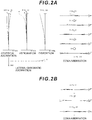
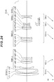
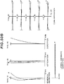
- FIGS. 2A and 2B are graphs showing various aberrations of the zoom optical system having the vibration-proof function according to the first example upon focusing on infinity in the wide-angle end state, and graphs showing meridional lateral aberrations when blur correction is applied to a rotational blur by 0.30°, respectively.
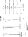
- FIG. 3 is graphs showing various aberrations of the zoom optical system having the vibration-proof function according to the first example upon focusing on infinity in the intermediate focal length state.
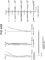
- FIGS. 4A and 4B are graphs showing various aberrations of the zoom optical system having the vibration-proof function according to the first example upon focusing on infinity in the telephoto end state, and graphs showing meridional lateral aberrations when blur correction is applied to a rotational blur by 0.20°, respectively.
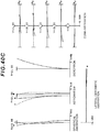
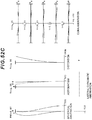
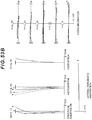
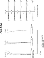
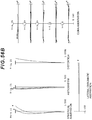
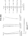
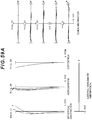
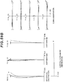
- FIGS. 5A , 5B and 5C are graphs showing various aberrations of the zoom optical system according to the first example upon focusing on a short distant object in the wide-angle end state, the intermediate focal length state, and the
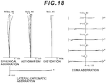
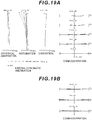
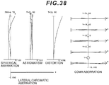
- FNO denotes the f-number
- NA denotes the numerical aperture
- Y denotes the image height.
- the spherical aberration graph shows the value of the f-number or the numerical aperture corresponding to the maximum aperture.
- the astigmatism graph and the distortion graph show the maximum value of the image height.
- the coma aberration graph shows the value of each image height.
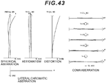
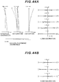
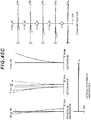
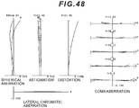
- solid lines indicate sagittal image surfaces, and broken lines indicate meridional image surfaces. Note that symbols analogous to those in this example are used also in the aberration graphs in the following examples.
- the graphs showing various aberrations show that the zoom optical system according to this example favorably corrects the various aberrations and has excellent image forming performances from the wide-angle end state to the telephoto end state, and further has excellent image forming performances also upon focusing on a short distant object.
- FIG. 6 shows a lens configuration of a zoom optical system according to the second example of the present application.
- the zoom optical system according to this example consists of, in order from the object: a first lens group G1 having a positive refractive power; a second lens group G2 having a negative refractive power; a third lens group G3 having a negative refractive power; a fourth lens group G4 having a positive refractive power; a fifth lens group G5 having a negative refractive power; and a sixth lens group G6 having a positive refractive power.
- the first lens group G1 corresponds to the front lens group GFS
- the second lens group G2 and the third lens group G3 correspond to the M1 lens group GM1
- the fourth lens group G4 corresponds to the M2 lens group GM2
- the fifth lens group G5 corresponds to the RN lens group GRN
- the sixth lens group G6 corresponds to the subsequent lens group GRS.
- the first lens group G1 consists of, in order from the object: a positive convexo-planar lens L11 having a convex surface facing the object; and a positive cemented lens consisting of a negative meniscus lens L12 having a convex surface facing the object, and a positive meniscus lens L13 having a convex surface facing the object.
- the second lens group G2 consists of, in order from the object: a negative meniscus lens L21 having a convex surface facing the object; a positive biconvex lens L22; and a negative biconcave lens L23.
- the third lens group G3 consists of a negative meniscus lens L31 having a concave surface facing the object.
- the fourth lens group G4 consists of, in order from the object: a positive cemented lens consisting of a negative meniscus lens L41 having a convex surface facing the object, and a positive biconvex lens L42; a positive cemented lens consisting of a positive biconvex lens L43, and a negative biconcave lens L44; an aperture stop S; a negative cemented lens consisting of a negative meniscus lens L45 having a convex surface facing the object, and a positive biconvex lens L46; and a positive biconvex lens L47.
- the fifth lens group G5 consists of, in order from the object: a positive meniscus lens L51 having a concave surface facing the object; and a negative biconcave lens L52.
- the sixth lens group G6 consists of, in order from the object: a negative meniscus lens L61 having a concave surface facing the object; and a positive biconvex lens L62.
- focusing from a long distant object to a short distant object is performed by moving the fifth lens group G5 in the image surface direction.
- the imaging position displacement due to a camera shake or the like is corrected by moving the positive cemented lens that consists of the negative meniscus lens L41 having the convex surface facing the object and the positive biconvex lens L42 and is included in the fourth lens group G4 (M2 lens group GM2), in a direction orthogonal to the optical axis.
- the movable lens group for blur correction is moved in a direction orthogonal to the optical axis by (f ⁇ tan ⁇ )/K.
- the vibration proof coefficient is 1.66
- the focal length is 72.1 mm. Accordingly, the amount of movement of the vibration-proof lens group to correct a rotational blur by 0.30° is 0.23 mm.
- the vibration proof coefficient is 2.10
- the focal length is 292.0 mm. Accordingly, the amount of movement of the vibration-proof lens group to correct a rotational blur by 0.20° is 0.49 mm.
- Table 2 lists the values of data on the optical system according to this example.
- Table 2 Second Example [Lens data] Surface No. R D nd ⁇ d Object surface ⁇ 1 107.5723 4.600 1.48749 70.32 2 ⁇ 0.200 3 96.9007 1.800 1.62004 36.40 4 47.8324 7.200 1.49700 81.61 5 361.3792 Variable 6 139.8663 1.700 1.69680 55.52 7 33.7621 6.806 8 33.5312 5.500 1.78472 25.64 9 -139.8348 0.637 10 -492.0620 1.300 1.80400 46.60 11 35.1115 Variable 12 -34.6163 1.200 1.83400 37.18 13 -377.1306 Variable 14 74.8969 1.200 1.80100 34.92 15 31.6202 5.900 1.64000 60.19 16 -69.0444 1.500 17 34.2668 6.000 1.48749 70.32 18 -42.8334 1.300 1.80610 40.97 19
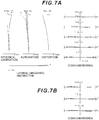
- FIGS. 7A and 7B are graphs showing various aberrations of the zoom optical system having the vibration-proof function according to the second example upon focusing on infinity in the wide-angle end state, and graphs showing meridional lateral aberrations when blur correction is applied to a rotational blur by 0.30°, respectively.
- FIG. 8 is graphs showing various aberrations of the zoom optical system having the vibration-proof function according to the second example upon focusing on infinity in the intermediate focal length state.
- FIGS. 9A and 9B are graphs showing various aberrations of the zoom optical system having the vibration-proof function according to the second example upon focusing on infinity in the telephoto end state, and graphs showing meridional lateral aberrations when blur correction is applied to a rotational blur by 0.20°, respectively.
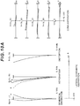
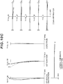
- FIGS. 10A , 10B and 10C are graphs showing various aberrations of the zoom optical system according to the second example upon focusing on a short distant object in the wide-angle end state, the intermediate focal length state, and the
- the graphs showing various aberrations show that the zoom optical system according to this example favorably corrects the various aberrations and has excellent image forming performances from the wide-angle end state to the telephoto end state, and further has excellent image forming performances also upon focusing on a short distant object.
- FIG. 11 shows a lens configuration of a zoom optical system according to the third example of the present application.
- the zoom optical system according to this example consists of, in order from the object: a first lens group G1 having a positive refractive power; a second lens group G2 having a negative refractive power; a third lens group G3 having a positive refractive power; a fourth lens group G4 having a positive refractive power; a fifth lens group G5 having a negative refractive power; and a sixth lens group G6 having a positive refractive power.
- the first lens group G1 corresponds to the front lens group GFS
- the second lens group G2 corresponds to the M1 lens group GM1
- the third lens group G3 and the fourth lens group G4 correspond to the M2 lens group GM2
- the fifth lens group G5 corresponds to the RN lens group GRN
- the sixth lens group G6 corresponds to the subsequent lens group GRS.
- the first lens group G1 consists of, in order from the object: a positive convexo-planar lens L11 having a convex surface facing the object; and a positive cemented lens consisting of a negative meniscus lens L12 having a convex surface facing the object, and a positive meniscus lens L13 having a convex surface facing the object.
- the second lens group G2 consists of, in order from the object: a negative meniscus lens L21 having a convex surface facing the object; a positive biconvex lens L22; a negative biconcave lens L23; and a negative meniscus lens L24 having a concave surface facing the object.
- the third lens group G3 consists of, in order from the object: a positive cemented lens consisting of a negative meniscus lens L31 having a convex surface facing the object, and a positive biconvex lens L32; a positive cemented lens consisting of a positive biconvex lens L33, and a negative biconcave lens L34; and an aperture stop S.
- the fourth lens group G4 consists of, in order from the object: a negative cemented lens consisting of a negative meniscus lens L41 having a convex surface facing the object, and a positive biconvex lens L42; and a positive biconvex lens L43.
- the fifth lens group G5 consists of, in order from the object: a positive meniscus lens L51 having a concave surface facing the object; and a negative biconcave lens L52.
- the sixth lens group G6 consists of, in order from the object: a negative meniscus lens L61 having a concave surface facing the object; and a positive biconvex lens L62.
- focusing from a long distant object to a short distant object is performed by moving the fifth lens group G5 in the image surface direction.
- the imaging position displacement due to a camera shake or the like is corrected by moving the positive cemented lens that consists of the negative meniscus lens L31 having the convex surface facing the object and the positive biconvex lens L32 and is included in the third lens group G3 (M2 lens group GM2), in a direction orthogonal to the optical axis.
- the movable lens group for blur correction is moved in a direction orthogonal to the optical axis by (f ⁇ tan ⁇ )/K.
- the vibration proof coefficient is 1.65
- the focal length is 72.1 mm. Accordingly, the amount of movement of the vibration-proof lens group to correct a rotational blur by 0.30° is 0.23 mm.
- the vibration proof coefficient is 2.10
- the focal length is 292.0 mm. Accordingly, the amount of movement of the vibration-proof lens group to correct a rotational blur by 0.20° is 0.49 mm.
- Table 3 lists the values of data on the optical system according to this example.
- Table 3 Third Example [Lens data] Surface No. R D nd ⁇ d Object surface ⁇ 1 106.7563 4.600 1.48749 70.32 2 ⁇ 0.200 3 99.4635 1.800 1.62004 36.40 4 49.2336 7.200 1.49700 81.61 5 332.7367 Variable 6 152.3830 1.700 1.69680 55.52 7 31.0229 5.695 8 32.0867 5.500 1.78472 25.64 9 -139.5695 1.399 10 -403.4713 1.300 1.77250 49.62 11 33.8214 4.300 12 -34.0003 1.200 1.85026 32.35 13 -235.0206 Variable 14 69.3622 1.200 1.80100 34.92 15 29.8420 5.900 1.64000 60.19 16 -71.2277 1.500 17 34.4997 6.000 1.48749 70.32 18 -43.1246 1.300 1.80610 40.97 19 382.
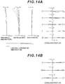
- FIGS. 12A and 12B are graphs showing various aberrations of the zoom optical system having a vibration-proof function according to the third example upon focusing on infinity in the wide-angle end state, and graphs showing meridional lateral aberrations when blur correction is applied to a rotational blur by 0.30°, respectively.
- FIG. 13 is graphs showing various aberrations of the zoom optical system having the vibration-proof function according to the third example upon focusing on infinity in the intermediate focal length state.
- FIGS. 12A and 12B are graphs showing various aberrations of the zoom optical system having a vibration-proof function according to the third example upon focusing on infinity in the wide-angle end state, and graphs showing meridional lateral aberrations when blur correction is applied to a rotational blur by 0.30°, respectively.
- FIG. 13 is graphs showing various aberrations of the zoom optical system having the vibration-proof function according to the third example upon focusing on infinity in the intermediate focal length state.
- FIGS. 15A , 15B and 15C are graphs showing various aberrations of the zoom optical system according to the third example upon focusing on a short distant object in the wide-angle end state, the intermediate focal length state, and the telephoto end state, respectively.
- the graphs showing various aberrations show that the zoom optical system according to this example favorably corrects the various aberrations and has excellent image forming performances from the wide-angle end state to the telephoto end state, and further has excellent image forming performances also upon focusing on a short distant object.
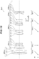
- FIG. 16 shows a lens configuration of a zoom optical system according to the fourth example of the present application.
- the zoom optical system according to this example consists of, in order from the object: a first lens group G1 having a positive refractive power; a second lens group G2 having a negative refractive power; a third lens group G3 having a positive refractive power; a fourth lens group G4 having a negative refractive power; and a fifth lens group G5 having a positive refractive power.
- the first lens group G1 corresponds to the front lens group GFS
- the second lens group G2 corresponds to the M1 lens group GM1
- the third lens group G3 corresponds to the M2 lens group GM2
- the fourth lens group G4 corresponds to the RN lens group GRN
- the fifth lens group G5 corresponds to the subsequent lens group GRS.
- the first lens group G1 consists of, in order from the object: a positive convexo-planar lens L11 having a convex surface facing the object; and a positive cemented lens consisting of a negative meniscus lens L12 having a convex surface facing the object, and a positive meniscus lens L13 having a convex surface facing the object.
- the second lens group G2 consists of, in order from the object: a negative meniscus lens L21 having a convex surface facing the object; a positive biconvex lens L22; a negative biconcave lens L23; and a negative meniscus lens L24 having a concave surface facing the object.
- the third lens group G3 consists of, in order from the object: a positive cemented lens consisting of a negative meniscus lens L31 having a convex surface facing the object, and a positive biconvex lens L32; a positive cemented lens consisting of a positive biconvex lens L33, and a negative biconcave lens L34; an aperture stop S; a negative cemented lens consisting of a negative meniscus lens L35 having a convex surface facing the object, and a positive biconvex lens L36; and a positive biconvex lens L37.
- the fourth lens group G4 consists of, in order from the object: a positive meniscus lens L41 having a concave surface facing the object; and a negative biconcave lens L42.
- the fifth lens group G5 consists of, in order from the object: a negative meniscus lens L51 having a concave surface facing the object; a positive biconvex lens L52; and a positive meniscus lens L53 having a convex surface facing the object.
- focusing from a long distant object to a short distant object is performed by moving the fourth lens group G4 in the image surface direction.
- the imaging position displacement due to a camera shake or the like is corrected by moving the positive cemented lens that consists of the negative meniscus lens L31 having the convex surface facing the object and the positive biconvex lens L32 and is included in the third lens group G3 (M2 lens group GM2), in a direction orthogonal to the optical axis.
- the movable lens group for blur correction is moved in a direction orthogonal to the optical axis by (f ⁇ tan ⁇ )/K.
- the vibration proof coefficient is 1.65
- the focal length is 72.1 mm. Accordingly, the amount of movement of the vibration-proof lens group to correct a rotational blur by 0.30° is 0.23 mm.
- the vibration proof coefficient is 2.10
- the focal length is 292.0 mm. Accordingly, the amount of movement of the vibration-proof lens group to correct a rotational blur by 0.20° is 0.49 mm.
- Table 4 lists the values of data on the optical system according to this example.
- Table 4 Fourth Example [Lens data] Surface No. R D nd ⁇ d Object surface ⁇ 1 109.5099 4.600 1.48749 70.32 2 ⁇ 0.200 3 101.8486 1.800 1.62004 36.40 4 49.8873 7.200 1.49700 81.61 5 403.0130 Variable 6 166.1577 1.700 1.69680 55.52 7 31.1882 3.953 8 32.0256 5.500 1.78472 25.64 9 -139.5816 1.553 10 -767.2482 1.300 1.77250 49.62 11 33.9202 4.300 12 -32.8351 1.200 1.85026 32.35 13 -256.2484 Variable 14 69.5902 1.200 1.80100 34.92 15 29.9877 5.900 1.64000 60.19 16 -70.0411 1.500 17 36.2271 6.000 1.48749 70.32 18 -39.9358 1.300 1.80610 40.97 19
- FIGS. 17A and 17B are graphs showing various aberrations of the zoom optical system having a vibration-proof function according to the fourth example upon focusing on infinity in the wide-angle end state, and graphs showing meridional lateral aberrations when blur correction is applied to a rotational blur by 0.30°, respectively.
- FIG. 18 is graphs showing various aberrations of the zoom optical system having the vibration-proof function according to the fourth example upon focusing on infinity in the intermediate focal length state.
- FIGS. 20A , 20B and 20C are graphs showing various aberrations of the zoom optical system according to the fourth example upon focusing on a short distant object in the wide-angle end state, the intermediate focal length state, and the telephoto end state, respectively.
- the graphs showing various aberrations show that the zoom optical system according to this example favorably corrects the various aberrations and has excellent image forming performances from the wide-angle end state to the telephoto end state, and further has excellent image forming performances also upon focusing on a short distant object.
- FIG. 21 shows a lens configuration of a zoom optical system according to the fifth example of this embodiment.
- the zoom optical system ZL(5) according to the fifth example consists of, in order from the object: a first lens group G1 having a positive refractive power; a second lens group G2 having a negative refractive power; a third lens group G3 having a positive refractive power; a fourth lens group G4 having a negative refractive power; and a fifth lens group G5 having a positive refractive power.
- W wide-angle end state
- T telephoto end state
- the first lens group G1 corresponds to the front lens group GFS
- the second lens group G2 corresponds to the M1 lens group GM1
- the third lens group G3 corresponds to the M2 lens group GM2
- the fourth lens group G4 corresponds to the RN lens group GRN
- the fifth lens group G5 corresponds to the subsequent lens group GRS.
- the first lens group G1 consists of, in order from the object: a positive meniscus lens L11 having a convex surface facing the object; and a positive cemented lens consisting of a negative meniscus lens L12 having a convex surface facing the object, and a positive biconvex lens L13.
- the second lens group G2 consists of, in order from the object: a negative meniscus lens L21 having a convex surface facing the object; a positive biconvex lens L22; a negative biconcave lens L23; and a negative cemented lens consisting of a negative biconcave lens L24, and a positive meniscus lens L25 having a convex surface facing the object.
- the third lens group G3 consists of, in order from the object: a positive biconvex lens L31; a positive cemented lens consisting of a positive biconvex lens L32 and a negative biconcave lens L33; an aperture stop S; a positive cemented lens consisting of a negative meniscus lens L34 having a convex surface facing the object, and a positive biconvex lens L35; and a positive biconvex lens L36.
- the fourth lens group G4 consists of, in order from the object: a positive meniscus lens L41 having a concave surface facing the object; and a negative biconcave lens L42.
- the fifth lens group G5 consists of, in order from the object: a negative meniscus lens L51 having a concave surface facing the object; and a positive meniscus lens L52 having a convex surface facing the object.
- An image surface I is disposed to the image side of the fifth lens group G5.
- the entire fourth lens group G4 constitutes the focusing lens group, and focusing from a long distant object to a short distant object is performed by moving the entire fourth lens group G4 in the image surface direction.
- the negative cemented lens which consists of the negative lens L24 and the positive meniscus lens L25 and is included in the second lens group G2 (M1 lens group GM1), constitutes the vibration-proof lens group movable in a direction perpendicular to the optical axis, and corrects the imaging position displacement (image blur on the image surface I) due to a camera shake or the like.
- the movable lens group for blur correction is moved in a direction orthogonal to the optical axis by (f ⁇ tan ⁇ )/K.
- the vibration proof coefficient is 0.97
- the focal length is 72.1 mm. Accordingly, the amount of movement of the vibration-proof lens group to correct a rotational blur by 0.30° is 0.39 mm.
- the vibration proof coefficient is 2.01, and the focal length is 292.0 mm. Accordingly, the amount of movement of the vibration-proof lens group to correct a rotational blur by 0.20° is 0.51 mm.
- Table 5 lists the values of data on the optical system according to the fifth example.
- Table 5 Fifth Example [Lens data] Surface No. R D nd ⁇ d Object surface ⁇ 1 121.1094 4.980 1.48749 70.31 2 474.6427 0.200 3 104.9110 1.700 1.83400 37.18 4 63.9583 9.069 1.49700 81.73 5 -1816.1542 Variable 6 153.9285 1.000 1.83400 37.18 7 37.0130 9.180 8 41.8122 5.321 1.80518 25.45 9 -148.0087 1.552 10 -153.0936 1.000 1.90366 31.27 11 74.4958 4.888 12 -65.0702 1.000 1.69680 55.52 13 35.9839 3.310 1.83400 37.18 14 121.5659 Variable 15 85.1793 3.534 1.80400 46.60 16 -101.3301 0.200 17 38.9890 5.033 1.49700 81.73 18 -62.2191 1.200
- FIGS. 22A and 22B are graphs showing various aberrations of the zoom optical system having a vibration-proof function according to the fifth example upon focusing on infinity in the wide-angle end state, and graphs showing meridional lateral aberrations when blur correction is applied to a rotational blur by 0.30°, respectively.
- FIG. 23 is graphs showing various aberrations of the zoom optical system having the vibration-proof function according to the fifth example upon focusing on infinity in the intermediate focal length state.
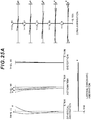
- FIGS. 24A and 24B are graphs showing various aberrations of the zoom optical system having a vibration-proof function according to the fifth example upon focusing on infinity in the telephoto end state, and graphs showing meridional lateral aberrations when blur correction is applied to a rotational blur by 0.20°, respectively.
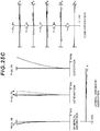
- FIGS. 25A , 25B and 25C are graphs showing various aberrations of the zoom optical system according to the fifth example upon focusing on a short distant object in the wide-angle end state, the intermediate focal length state, and the telephoto end state, respectively.
- the graphs showing various aberrations show that the zoom optical system according to fifth example favorably corrects the various aberrations and has excellent image forming performances from the wide-angle end state to the telephoto end state, and further has excellent image forming performances also upon focusing on a short distant object.
- FIG. 26 shows a lens configuration of a zoom optical system according to the sixth example of this embodiment.
- the zoom optical system ZL(6) according to the sixth example consists of, in order from the object: a first lens group G1 having a positive refractive power; a second lens group G2 having a negative refractive power; a third lens group G3 having a positive refractive power; a fourth lens group G4 having a negative refractive power; and a fifth lens group G5 having a negative refractive power.
- W wide-angle end state
- T telephoto end state
- the first lens group G1 corresponds to the front lens group GFS
- the second lens group G2 corresponds to the M1 lens group GM1
- the third lens group G3 corresponds to the M2 lens group GM2
- the fourth lens group G4 corresponds to the RN lens group GRN
- the fifth lens group G5 corresponds to the subsequent lens group GRS.
- the first lens group G1 consists of, in order from the object: a positive meniscus lens L11 having a convex surface facing the object; and a positive cemented lens consisting of a negative meniscus lens L12 having a convex surface facing the object, and a positive biconvex lens L13.
- the second lens group G2 consists of, in order from the object: a negative meniscus lens L21 having a convex surface facing the object; a positive cemented lens consisting of a positive biconvex lens L22 and a negative biconcave lens L23; and a negative cemented lens consisting of a negative biconcave lens L24, and a positive meniscus lens L25 having a convex surface facing the object.
- the third lens group G3 consists of, in order from the object: a positive biconvex lens L31; a positive cemented lens consisting of a positive biconvex lens L32 and a negative biconcave lens L33; an aperture stop S; a negative cemented lens consisting of a negative meniscus lens L34 having a convex surface facing the object, and a positive meniscus lens L35 having a convex surface facing the object; and a positive biconvex lens L36.
- the fourth lens group G4 consists of, in order from the object: a positive meniscus lens L41 having a concave surface facing the object; and a negative biconcave lens L42.
- the fifth lens group G5 consists of, in order from the object: a negative meniscus lens L51 having a concave surface facing the object; and a positive meniscus lens L52 having a convex surface facing the object.
- An image surface I is disposed to the image side of the fifth lens group G5.
- the entire fourth lens group G4 constitutes the focusing lens group, and focusing from a long distant object to a short distant object is performed by moving the entire fourth lens group G4 in the image surface direction.
- the negative cemented lens which consists of the negative lens L24 and the positive meniscus lens L25 and is included in the second lens group G2 (M1 lens group GM1), constitutes the vibration-proof lens group movable in a direction perpendicular to the optical axis, and corrects the imaging position displacement (image blur on the image surface I) due to a camera shake or the like.
- the movable lens group for blur correction is moved in a direction orthogonal to the optical axis by (f ⁇ tan ⁇ )/K.
- the vibration proof coefficient is 0.93
- the focal length is 72.1 mm. Accordingly, the amount of movement of the vibration-proof lens group to correct a rotational blur by 0.30° is 0.41 mm.
- the vibration proof coefficient is 1.90
- the focal length is 292.0 mm. Accordingly, the amount of movement of the vibration-proof lens group to correct a rotational blur by 0.20° is 0.54 mm.
- Table 6 lists the values of data on the optical system according to the sixth example.
- Table 6 Sixth Example [Lens data] Surface No. R D nd ⁇ d Object surface ⁇ 1 114.5391 5.639 1.48749 70.31 2 663.8041 0.200 3 103.9783 1.700 1.83400 37.18 4 62.4686 8.805 1.49700 81.73 5 -43979.1830 Variable 6 146.6152 1.000 1.77250 49.62 7 35.8241 11.693 8 37.5245 4.696 1.68893 31.16 9 -254.6834 1.000 1.83400 37.18 10 64.6045 5.066 11 -60.5874 1.000 1.56883 56.00 12 39.1203 2.952 1.75520 27.57 13 93.1442 Variable 14 92.3597 3.688 1.80400 46.60 15 -87.7395 0.200 16 36.8528 5.291 1.49700 81.73 17 -63.3187 1.200 1.95000 29.37
- FIGS. 27A and 27B are graphs showing various aberrations of the zoom optical system having a vibration-proof function according to the sixth example upon focusing on infinity in the wide-angle end state, and graphs showing meridional lateral aberrations when blur correction is applied to a rotational blur by 0.30°, respectively.
- FIG. 28 is graphs showing various aberrations of the zoom optical system having the vibration-proof function according to the sixth example upon focusing on infinity in the intermediate focal length state.
- FIGS. 30A , 30B and 30C are graphs showing various aberrations of the zoom optical system according to the sixth example upon focusing on a short distant object in the wide-angle end state, the intermediate focal length state, and the telephoto end state, respectively.
- the graphs showing various aberrations show that the zoom optical system according to sixth example favorably corrects the various aberrations and has excellent image forming performances from the wide-angle end state to the telephoto end state, and further has excellent image forming performances also upon focusing on a short distant object.
- FIG. 31 shows a lens configuration of a zoom optical system according to the seventh example of this embodiment.
- the zoom optical system ZL(7) according to the seventh example consists of, in order from the object: a first lens group G1 having a positive refractive power; a second lens group G2 having a negative refractive power; a third lens group G3 having a positive refractive power; a fourth lens group G4 having a negative refractive power; and a fifth lens group G5 having a positive refractive power.
- W wide-angle end state
- T telephoto end state
- the first lens group G1 corresponds to the front lens group GFS
- the second lens group G2 corresponds to the M1 lens group GM1
- the third lens group G3 corresponds to the M2 lens group GM2
- the fourth lens group G4 corresponds to the RN lens group GRN
- the fifth lens group G5 corresponds to the subsequent lens group GRS.
- the first lens group G1 consists of, in order from the object: a positive biconvex lens L11; and a positive cemented lens consisting of a negative meniscus lens L12 having a convex surface facing the object, and a positive biconvex lens L13.
- the second lens group G2 consists of, in order from the object: a negative meniscus lens L21 having a convex surface facing the object; a positive cemented lens consisting of a positive biconvex lens L22 and a negative biconcave lens L23; and a negative cemented lens consisting of a negative biconcave lens L24, and a positive meniscus lens L25 having a convex surface facing the object.
- the third lens group G3 consists of, in order from the object: a positive biconvex lens L31; a positive cemented lens consisting of a positive biconvex lens L32 and a negative biconcave lens L33; an aperture stop S; and a positive cemented lens consisting of a negative meniscus lens L34 having a convex surface facing the object, and a positive biconvex lens L35.
- the fourth lens group G4 consists of, in order from the object: a positive meniscus lens L41 having a concave surface facing the object; and a negative biconcave lens L42.
- the fifth lens group G5 consists of, in order from the object: a negative meniscus lens L51 having a concave surface facing the object; and a positive biconvex lens L52.
- An image surface I is disposed to the image side of the fifth lens group G5.
- the entire fourth lens group G4 constitutes the focusing lens group, and focusing from a long distant object to a short distant object is performed by moving the entire fourth lens group G4 in the image surface direction.
- the negative cemented lens which consists of the negative lens L24 and the positive meniscus lens L25 and is included in the second lens group G2 (M1 lens group GM1), constitutes the vibration-proof lens group movable in a direction perpendicular to the optical axis, and corrects the imaging position displacement (image blur on the image surface I) due to a camera shake or the like.
- the movable lens group for blur correction is moved in a direction orthogonal to the optical axis by (f ⁇ tan ⁇ )/K.
- the vibration proof coefficient is 0.96
- the focal length is 72.1 mm. Accordingly, the amount of movement of the vibration-proof lens group to correct a rotational blur by 0.30° is 0.39 mm.
- the vibration proof coefficient is 2.00
- the focal length is 292.0 mm. Accordingly, the amount of movement of the vibration-proof lens group to correct a rotational blur by 0.20° is 0.51 mm.
- Table 7 lists the values of data on the optical system according to the seventh example.
- Table 7 Seventh Example [Lens data] Surface No. R D nd ⁇ d Object surface ⁇ 1 268.8673 3.827 1.48749 70.31 2 -1922.6559 0.200 3 111.5860 1.700 1.62004 36.40 4 61.6123 8.761 1.49700 81.73 5 -1745.4439 Variable 6 124.2629 1.000 1.77250 49.62 7 34.3759 7.147 8 35.3149 5.189 1.60342 38.03 9 -190.5775 1.000 1.77250 49.62 10 75.4448 4.904 11 -65.2960 1.000 1.67003 47.14 12 37.2634 3.301 1.80518 25.45 13 119.9726 Variable 14 80.9765 3.968 1.77250 49.62 15 -78.4621 0.200 16 33.2120 5.701 1.49700 81.73 17 -56.7466 1.200 1.85026 32.35 18
- FIGS. 32A and 32B are graphs showing various aberrations of the zoom optical system having a vibration-proof function according to the seventh example upon focusing on infinity in the wide-angle end state, and graphs showing meridional lateral aberrations when blur correction is applied to a rotational blur by 0.30°, respectively.
- FIG. 33 is graphs showing various aberrations of the zoom optical system having the vibration-proof function according to the seventh example upon focusing on infinity in the intermediate focal length state.
- FIGS. 35A , 35B and 35C are graphs showing various aberrations of the zoom optical system according to the seventh example upon focusing on a short distant object in the wide-angle end state, the intermediate focal length state, and the telephoto end state, respectively.
- the graphs showing various aberrations show that the zoom optical system according to seventh example favorably corrects the various aberrations and has excellent image forming performances from the wide-angle end state to the telephoto end state, and further has excellent image forming performances also upon focusing on a short distant object.
- FIG. 36 shows a lens configuration of a zoom optical system according to the eighth example of this embodiment.
- the zoom optical system ZL(8) according to the eighth example consists of, in order from the object: a first lens group G1 having a positive refractive power; a second lens group G2 having a negative refractive power; a third lens group G3 having a positive refractive power; a fourth lens group G4 having a negative refractive power; and a fifth lens group G5 having a positive refractive power.
- W wide-angle end state
- T telephoto end state
- the first lens group G1 corresponds to the front lens group GFS
- the second lens group G2 corresponds to the M1 lens group GM1
- the third lens group G3 corresponds to the M2 lens group GM2
- the fourth lens group G4 corresponds to the RN lens group GRN
- the fifth lens group G5 corresponds to the subsequent lens group GRS.
- the first lens group G1 consists of, in order from the object: a positive biconvex lens L11; and a positive cemented lens consisting of a negative meniscus lens L12 having a convex surface facing the object, and a positive biconvex lens L13.
- the second lens group G2 consists of, in order from the object: a negative meniscus lens L21 having a convex surface facing the object; a positive cemented lens consisting of a positive biconvex lens L22 and a negative biconcave lens L23; and a negative cemented lens consisting of a negative biconcave lens L24, and a positive meniscus lens L25 having a convex surface facing the object.
- the third lens group G3 consists of, in order from the object: a positive biconvex lens L31; a positive cemented lens consisting of a positive biconvex lens L32 and a negative biconcave lens L33; an aperture stop S; and a positive cemented lens consisting of a negative meniscus lens L34 having a convex surface facing the object, and a positive biconvex lens L35.
- the fourth lens group G4 consists of, in order from the object: a positive meniscus lens L41 having a concave surface facing the object; and a negative biconcave lens L42.
- the fifth lens group G5 consists of: a negative meniscus lens L51 having a concave surface facing the object; and a positive biconvex lens L52.
- An image surface I is disposed to the image side of the fifth lens group G5.
- the positive meniscus lens L41 and the negative lens L42 in the fourth lens group G4 constitute the focusing lens group, and focusing from a long distant object to a short distant object is performed by moving the positive meniscus lens L41 and the negative lens L42 in the fourth lens group G4 in the image surface direction.
- the negative cemented lens which consists of the negative lens L24 and the positive meniscus lens L25 and is included in the second lens group G2 (M1 lens group GM1), constitutes the vibration-proof lens group movable in a direction perpendicular to the optical axis, and corrects the imaging position displacement (image blur on the image surface I) due to a camera shake or the like.
- the movable lens group for blur correction is moved in a direction orthogonal to the optical axis by (f ⁇ tan ⁇ )/K.
- the vibration proof coefficient is 1.05
- the focal length is 72.1 mm. Accordingly, the amount of movement of the vibration-proof lens group to correct a rotational blur by 0.30° is 0.36 mm.
- the vibration proof coefficient is 2.20
- the focal length is 292.0 mm. Accordingly, the amount of movement of the vibration-proof lens group to correct a rotational blur by 0.20° is 0.46 mm.
- Table 8 lists the values of data on the optical system according to the eighth example.
- Table 8 Eighth Example [Lens data ] Surface No. R D nd ⁇ d Object surface ⁇ 1 384.8872 4.307 1.48749 70.31 2 -459.3665 0.200 3 108.5471 1.700 1.62004 36.40 4 59.1633 8.722 1.49700 81.73 5 -3828.8091 Variable 6 116.0785 1.000 1.77250 49.62 7 33.3782 6.789 8 34.8547 5.123 1.64769 33.73 9 -166.2311 1.000 1.80400 46.60 10 68.6485 5.021 11 -58.3172 1.000 1.66755 41.87 12 33.1524 3.543 1.80518 25.45 13 108.5224 Variable 14 80.6236 4.111 1.77250 49.62 15 -73.7947 0.200 16 32.8485 5.846 1.49700 81.73 17 -53.4390 1.200
- FIGS. 37A and 37B are graphs showing various aberrations of the zoom optical system having a vibration-proof function according to the eighth example upon focusing on infinity in the wide-angle end state, and graphs showing meridional lateral aberrations when blur correction is applied to a rotational blur by 0.30°, respectively.
- FIG. 38 is graphs showing various aberrations of the zoom optical system having the vibration-proof function according to the eighth example upon focusing on infinity in the intermediate focal length state.
- FIGS. 40A , 40B and 40C are graphs showing various aberrations of the zoom optical system according to the eighth example upon focusing on a short distant object in the wide-angle end state, the intermediate focal length state, and the telephoto end state, respectively.
- the graphs showing various aberrations show that the zoom optical system according to eighth example favorably corrects the various aberrations and has excellent image forming performances from the wide-angle end state to the telephoto end state, and further has excellent image forming performances also upon focusing on a short distant object.
- FIG. 41 shows a lens configuration of a zoom optical system according to the ninth example of this embodiment.
- the zoom optical system ZL(9) according to the ninth example consists of, in order from the object: a first lens group G1 having a positive refractive power; a second lens group G2 having a negative refractive power; a third lens group G3 having a positive refractive power; a fourth lens group G4 having a negative refractive power; and a fifth lens group G5 having a positive refractive power.
- W wide-angle end state
- T telephoto end state
- the first lens group G1 corresponds to the front lens group GFS
- the second lens group G2 corresponds to the M1 lens group GM1
- the third lens group G3 corresponds to the M2 lens group GM2
- the fourth lens group G4 corresponds to the RN lens group GRN
- the fifth lens group G5 corresponds to the subsequent lens group GRS.
- the first lens group G1 consists of, in order from the object: a positive biconvex lens L11; and a positive cemented lens consisting of a negative meniscus lens L12 having a convex surface facing the object, and a positive biconvex lens L13.
- the second lens group G2 consists of, in order from the object: a negative meniscus lens L21 having a convex surface facing the object; a positive meniscus lens L22 having a convex surface facing the object; and a negative cemented lens consisting of a negative biconcave lens L23, and a positive meniscus lens L24 having a convex surface facing the object.
- the third lens group G3 consists of, in order from the object: a positive biconvex lens L31; a positive cemented lens consisting of a positive biconvex lens L32 and a negative biconcave lens L33; an aperture stop S; and a positive cemented lens consisting of a negative meniscus lens L34 having a convex surface facing the object, and a positive biconvex lens L35.
- the fourth lens group G4 consists of, in order from the object: a positive meniscus lens L41 having a concave surface facing the object; and a negative biconcave lens L42.
- the fifth lens group G5 consists of, in order from the object: a negative meniscus lens L51 having a concave surface facing the object; and a positive biconvex lens L52.
- An image surface I is disposed to the image side of the fifth lens group G5.
- the entire fourth lens group G4 constitutes the focusing lens group, and focusing from a long distant object to a short distant object is performed by moving the entire fourth lens group G4 in the image surface direction.
- the negative cemented lens which consists of the negative lens L23 and the positive meniscus lens L24 and is included in the second lens group G2 (M1 lens group GM1), constitutes the vibration-proof lens group movable in a direction perpendicular to the optical axis, and corrects the imaging position displacement (image blur on the image surface I) due to a camera shake or the like.
- the movable lens group for blur correction is moved in a direction orthogonal to the optical axis by (f ⁇ tan ⁇ )/K.
- the vibration proof coefficient is 1.02
- the focal length is 72.1 mm. Accordingly, the amount of movement of the vibration-proof lens group to correct a rotational blur by 0.30° is 0.37 mm.
- the vibration proof coefficient is 2.10
- the focal length is 292.0 mm. Accordingly, the amount of movement of the vibration-proof lens group to correct a rotational blur by 0.20° is 0.49 mm.
- FIGS. 42A and 42B are graphs showing various aberrations of the zoom optical system having a vibration-proof function according to the ninth example upon focusing on infinity in the wide-angle end state, and graphs showing meridional lateral aberrations when blur correction is applied to a rotational blur by 0.30°, respectively.
- FIG. 43 is graphs showing various aberrations of the zoom optical system having the vibration-proof function according to the ninth example upon focusing on infinity in the intermediate focal length state.
- FIGS. 42A and 42B are graphs showing various aberrations of the zoom optical system having a vibration-proof function according to the ninth example upon focusing on infinity in the wide-angle end state, and graphs showing meridional lateral aberrations when blur correction is applied to a rotational blur by 0.30°, respectively.
- FIG. 43 is graphs showing various aberrations of the zoom optical system having the vibration-proof function according to the ninth example upon focusing on infinity in the intermediate focal length state.
- FIGS. 45A , 45B and 45C are graphs showing various aberrations of the zoom optical system according to the ninth example upon focusing on a short distant object in the wide-angle end state, the intermediate focal length state, and the telephoto end state, respectively.
- the graphs showing various aberrations show that the zoom optical system according to ninth example favorably corrects the various aberrations and has excellent image forming performances from the wide-angle end state to the telephoto end state, and further has excellent image forming performances also upon focusing on a short distant object.
- FIG. 46 shows a lens configuration of a zoom optical system according to the tenth example of this embodiment.
- the zoom optical system ZL(10) according to the tenth example consists of, in order from the object: a first lens group G1 having a positive refractive power; a second lens group G2 having a negative refractive power; a third lens group G3 having a positive refractive power; a fourth lens group G4 having a negative refractive power; and a fifth lens group G5 having a positive refractive power.
- W wide-angle end state
- T telephoto end state
- the first lens group G1 corresponds to the front lens group GFS
- the second lens group G2 corresponds to the M1 lens group GM1
- the third lens group G3 corresponds to the M2 lens group GM2
- the fourth lens group G4 corresponds to the RN lens group GRN
- the fifth lens group G5 corresponds to the subsequent lens group GRS.
- the first lens group G1 consists of, in order from the object: a positive cemented lens consisting of a negative meniscus lens L11 having a convex surface facing the object, and a positive biconvex lens L12; and a positive meniscus lens L13 having a convex surface facing the object.
- the second lens group G2 consists of, in order from the object: a positive biconvex lens L21; a negative biconcave lens L22; a positive meniscus lens L23 having a convex surface facing the object; and a negative cemented lens consisting of a negative biconcave lens L24, and a positive meniscus lens L25 having a convex surface facing the object.
- the third lens group G3 consists of, in order from the object: a positive biconvex lens L31; a positive cemented lens consisting of a positive biconvex lens L32 and a negative biconcave lens L33; an aperture stop S; and a positive cemented lens consisting of a negative meniscus lens L34 having a convex surface facing the object, and a positive biconvex lens L35.
- the fourth lens group G4 consists of, in order from the object: a positive biconvex lens L41; and a negative biconcave lens L42.
- the fifth lens group G5 consists of, in order from the object: a negative meniscus lens L51 having a concave surface facing the object; and a positive meniscus lens L52 having a convex surface facing the object.
- An image surface I is disposed to the image side of the fifth lens group G5.
- the entire fourth lens group G4 constitutes the focusing lens group, and focusing from a long distant object to a short distant object is performed by moving the entire fourth lens group G4 in the image surface direction.
- the negative cemented lens which consists of the negative lens L24 and the positive meniscus lens L25 and is included in the second lens group G2 (M1 lens group GM1), constitutes the vibration-proof lens group movable in a direction perpendicular to the optical axis, and corrects the imaging position displacement (image blur on the image surface I) due to a camera shake or the like.
- the movable lens group for blur correction is moved in a direction orthogonal to the optical axis by (f ⁇ tan ⁇ )/K.
- the vibration proof coefficient is 1.01
- the focal length is 72.1 mm. Accordingly, the amount of movement of the vibration-proof lens group to correct a rotational blur by 0.30° is 0.37 mm.
- the vibration proof coefficient is 2.10
- the focal length is 292.0 mm. Accordingly, the amount of movement of the vibration-proof lens group to correct a rotational blur by 0.20° is 0.49 mm.
- Table 10 lists the values of data on the optical system according to the tenth example.
- Table 10 Tenth Example [Lens data] Surface No. R D nd ⁇ d Object surface ⁇ 1 139.3408 1.700 1.64769 33.73 2 77.5654 9.455 1.49700 81.73 3 -496.0322 0.200 4 144.5249 3.734 1.48749 70.31 5 357.2933 Variable 6 142.3498 3.303 1.84666 23.80 7 -361.0297 1.824 8 -451.3220 1.300 1.83400 37.18 9 33.3045 7.193 10 35.8308 3.147 1.71736 29.57 11 69.2532 4.718 12 -63.1663 1.000 1.66755 41.87 13 34.7105 3.239 1.80518 25.45 14 102.2323 Variable 15 73.7312 3.697 1.77250 49.62 16 -95.2978 0.200 17 33.5557 5.512 1.49700 81
- FIGS. 47A and 47B are graphs showing various aberrations of the zoom optical system having a vibration-proof function according to the tenth example upon focusing on infinity in the wide-angle end state, and graphs showing meridional lateral aberrations when blur correction is applied to a rotational blur by 0.30°, respectively.
- FIG. 48 is graphs showing various aberrations of the zoom optical system having the vibration-proof function according to the tenth example upon focusing on infinity in the intermediate focal length state.
- FIGS. 50A , 50B and 50C are graphs showing various aberrations of the zoom optical system according to the tenth example upon focusing on a short distant object in the wide-angle end state, the intermediate focal length state, and the telephoto end state, respectively.
- the graphs showing various aberrations show that the zoom optical system according to tenth example favorably corrects the various aberrations and has excellent image forming performances from the wide-angle end state to the telephoto end state, and further has excellent image forming performances also upon focusing on a short distant object.
- FIG. 51 shows a lens configuration of a zoom optical system according to the eleventh example of this embodiment.
- the zoom optical system ZL(11) according to the eleventh example consists of, in order from the object: a first lens group G1 having a positive refractive power; a second lens group G2 having a negative refractive power; a third lens group G3 having a positive refractive power; a fourth lens group G4 having a negative refractive power; and a fifth lens group G5 having a positive refractive power.
- An aperture stop S is provided in the third lens group G3.
- An image surface I is provided to face the image surface side of the fifth lens group G5.
- the first lens group G1 corresponds to the front lens group GFS
- the second lens group G2 corresponds to the M1 lens group GM1
- the third lens group G3 corresponds to the M2 lens group GM2
- the fourth lens group G4 corresponds to the RN lens group GRN
- the fifth lens group G5 corresponds to the subsequent lens group GRS.
- the first lens group G1 consists of, in order from the object: a positive biconvex lens L11; and a positive cemented lens consisting of a negative meniscus lens L12 having a convex surface facing the object, and a positive meniscus lens L13 having a convex surface facing the object.
- the second lens group G2 consists of, in order from the object: a negative cemented lens consisting of a negative biconcave lens L21, and a positive meniscus lens L22 having a convex surface facing the object; and a negative biconcave lens L23.
- the third lens group G3 consists of, in order from the object: a positive biconvex lens L31; an aperture stop S; a positive cemented lens consisting of a positive biconvex lens L32 and a negative biconcave lens L33; a positive cemented lens consisting of a negative meniscus lens L34 having a convex surface facing the object, and a positive biconvex lens L35; and a positive meniscus lens L36 having a convex surface facing the object.
- the fourth lens group G4 consists of a negative cemented lens consisting of a positive meniscus lens L41 having a concave surface facing the object, and a negative biconcave lens L42.
- the fifth lens group G5 consists of a positive biconvex lens L51.
- the fourth lens group G4 (RN lens group GRN) in the image surface direction.
- the second lens group G2 (M1 lens group GM1) constitutes the vibration-proof lens group having displacement components in the optical axis and a direction perpendicular to the optical axis, and performs image blur correction (vibration proof, and camera shake correction) on the image surface I.
- Table 11 lists the values of data on the optical system according to the eleventh example.
- Table 11 Eleventh Example [Lens data] Surface No. R D nd vd Object surface ⁇ 1 91.1552 6.167 1.51680 63.88 2 -844.6033 0.204 3 92.5357 1.500 1.64769 33.73 4 45.6802 6.598 1.48749 70.31 5 154.0927 Variable 6 -211.4795 1.000 1.69680 55.52 7 22.5821 3.677 1.80518 25.45 8 60.3602 2.652 9 -46.9021 1.000 1.77250 49.62 10 299.7358 Variable 11 48.8916 3.796 1.69680 55.52 12 -131.4333 1.000 13 ⁇ 1.000 (Stop S) 14 39.8799 4.932 1.69680 55.52 15 -49.6069 1.000 1.85026 32.35 16 72.3703 8.805 17 57.3477 1.000 1.80100 34.
- FIGS. 52A , 52B and 52C are graphs showing various aberrations of the zoom optical system according to the eleventh example upon focusing on infinity in the wide-angle end state, the intermediate focal length state, and the telephoto end state, respectively.
- FIGS. 53A , 53B and 53C are graphs showing various aberrations of the zoom optical system according to the eleventh example upon focusing on a short distant object in the wide-angle end state, the intermediate focal length state, and the telephoto end state, respectively.
- the graphs showing various aberrations show that the zoom optical system according to this example favorably corrects the various aberrations and has excellent image forming performances from the wide-angle end state to the telephoto end state, and further has excellent image forming performances also upon focusing on a short distant object.
- FIG. 54 shows a lens configuration of a zoom optical system according to the twelfth example of this embodiment.
- the zoom optical system ZL(12) according to the twelfth example consists of, in order from the object: a first lens group G1 having a positive refractive power; a second lens group G2 having a negative refractive power; a third lens group G3 having a positive refractive power; a fourth lens group G4 having a negative refractive power; and a fifth lens group G5 having a positive refractive power.
- the first lens group G1 corresponds to the front lens group GFS
- the second lens group G2 corresponds to the M1 lens group GM1
- the third lens group G3 corresponds to the M2 lens group GM2
- the fourth lens group G4 corresponds to the RN lens group GRN
- the fifth lens group G5 corresponds to the subsequent lens group GRS.
- the first lens group G1 consists of, in order from the object: a positive biconvex lens L11; and a positive cemented lens consisting of a negative meniscus lens L12 having a convex surface facing the object, and a positive meniscus lens L13 having a convex surface facing the object.
- the second lens group G2 consists of, in order from the object: a negative cemented lens consisting of a negative biconcave lens L21, and a positive meniscus lens L22 having a convex surface facing the object; and a negative biconcave lens L23.
- the third lens group G3 consists of, in order from the object: a positive biconvex lens L31; a positive cemented lens consisting of a positive biconvex lens L32 and a negative biconcave lens L33; an aperture stop S; a positive cemented lens consisting of a negative meniscus lens L34 having a convex surface facing the object, and a positive biconvex lens L35; and a positive meniscus lens L36 having a convex surface facing the object.
- the fourth lens group G4 consists of a negative cemented lens consisting of a positive meniscus lens L41 having a concave surface facing the object, and a negative biconcave lens L42.
- the fifth lens group G5 consists of a positive meniscus lens L51 having a convex surface facing the object.
- the second lens group G2 (M1 lens group GM1) constitutes the vibration-proof lens group having displacement components in the optical axis and a direction perpendicular to the optical axis, and performs image blur correction (vibration proof, and camera shake correction) on the image surface I.
- Table 12 lists the values of data on the optical system according to the twelfth example.
- Table 12 Twelfth Example [Lens data] Surface No. R D nd vd Object surface ⁇ 1 100.0120 5.590 1.51680 63.88 2 -356.7115 0.200 3 87.0822 1.500 1.62004 36.40 4 36.8924 7.184 1.51680 63.88 5 131.1594 Variable 6 -122.1413 1.000 1.69680 55.52 7 20.4910 3.496 1.80518 25.45 8 49.8357 2.470 9 -48.8699 1.000 1.77250 49.62 10 8360.2394 Variable 11 56.6713 3.785 1.58913 61.22 12 -64.2309 0.200 13 35.4309 4.669 1.48749 70.31 14 -48.4394 1.000 1.80100 34.92 15 159.7328 1.860 16 ⁇ 16.684 (Stop S) 17 57.8297 1.000 1.
- FIGS. 55A , 55B and 55C are graphs showing various aberrations of the zoom optical system according to the twelfth example upon focusing on infinity in the wide-angle end state, the intermediate focal length state, and the telephoto end state, respectively.
- FIGS. 56A , 56B and 56C are graphs showing various aberrations of the zoom optical system according to the twelfth example upon focusing on a short distant object in the wide-angle end state, the intermediate focal length state, and the telephoto end state, respectively.
- the graphs showing various aberrations show that the zoom optical system according to this example favorably corrects the various aberrations and has excellent image forming performances from the wide-angle end state to the telephoto end state, and further has excellent image forming performances also upon focusing on a short distant object.
- FIG. 57 shows a lens configuration of a zoom optical system according to the thirteenth example of this embodiment.
- the zoom optical system ZL(13) according to the thirteenth example consists of, in order from the object: a first lens group G1 having a positive refractive power; a second lens group G2 having a negative refractive power; a third lens group G3 having a positive refractive power; a fourth lens group G4 having a negative refractive power; and a fifth lens group G5 having a positive refractive power.
- the first lens group G1 corresponds to the front lens group GFS
- the second lens group G2 corresponds to the M1 lens group GM1
- the third lens group G3 corresponds to the M2 lens group GM2
- the fourth lens group G4 corresponds to the RN lens group GRN
- the fifth lens group G5 corresponds to the subsequent lens group GRS.
- the first lens group G1 consists of, in order from the object: a positive biconvex lens L11; and a positive cemented lens consisting of a negative meniscus lens L12 having a convex surface facing the object, and a positive meniscus lens L13 having a convex surface facing the object.
- the second lens group G2 consists of, in order from the object: a negative cemented lens consisting of a negative biconcave lens L21, and a positive meniscus lens L22 having a convex surface facing the object; and a negative biconcave lens L23.
- the third lens group G3 consists of, in order from the object: a positive biconvex lens L31; a positive cemented lens consisting of a positive biconvex lens L32 and a negative biconcave lens L33; an aperture stop S; a positive cemented lens consisting of a negative meniscus lens L34 having a convex surface facing the object, and a positive biconvex lens L35; and a positive meniscus lens L36 having a convex surface facing the object.
- the fourth lens group G4 consists of: a negative cemented lens consisting of a positive meniscus lens L41 having a concave surface facing the object, and a negative biconcave lens L42; and a negative meniscus lens L43 having a convex surface facing the object.
- the fifth lens group G5 consists of a positive meniscus lens L51 having a convex surface facing the object.
- the optical system focusing from a long distant object to a short distant object is performed by moving the fourth lens group G4 in the image surface direction.
- the second lens group G2 (M1 lens group GM1) constitutes the vibration-proof lens group having displacement components in the optical axis and a direction perpendicular to the optical axis, and performs image blur correction (vibration proof, and camera shake correction) on the image surface I.
- Table 13 lists the values of data on the optical system according to the thirteenth example.
- Table 13 Thirteenth Example [Lens da ta] Surface No. R D nd vd Object surface ⁇ 1 102.5193 5.542 1.51680 63.88 2 -366.1796 0.200 3 90.4094 1.500 1.62004 36.40 4 37.8518 7.229 1.51680 63.88 5 144.7539 Variable 6 -163.5053 1.000 1.69680 55.52 7 20.5835 3.475 1.80518 25.45 8 48.1602 2.598 9 -47.4086 1.000 1.77250 49.62 10 4634.3570 Variable 11 57.6094 3.843 1.58913 61.22 12 -66.7307 0.200 13 36.4629 4.709 1.48749 70.31 14 -48.7603 1.000 1.80100 34.92 15 206.1449 1.786 16 ⁇ 16.497 (Stop S) 17 55.1101 1.000 1.80
- FIGS. 58A , 58B and 58C are graphs showing various aberrations of the zoom optical system according to the thirteenth example upon focusing on infinity in the wide-angle end state, the intermediate focal length state, and the telephoto end state, respectively.
- FIGS. 59A , 59B and 59C are graphs showing various aberrations of the zoom optical system according to the thirteenth example upon focusing on a short distant object in the wide-angle end state, the intermediate focal length state, and the telephoto end state, respectively.
- the graphs showing various aberrations show that the zoom optical system according to this example favorably corrects the various aberrations and has excellent image forming performances from the wide-angle end state to the telephoto end state, and further has excellent image forming performances also upon focusing on a short distant object.
- reduction in size and weight of the focusing lens group can achieve high-speed AF and silence during AF without increasing the size of the lens barrel, and the zoom optical system can be achieved that favorably suppresses variation of aberrations upon zooming from the wide-angle end state to the telephoto end state, and variation of aberrations upon focusing from an infinite distant object to a short distant object.
- zoom optical systems having other group configurations for example, seven-group ones and the like
- a zoom optical system having a configuration where a lens or a lens group is added to the zoom optical system of the present application at a position nearest to the object or to the image surface may be configured.
- the lens group indicates a portion that has at least one lens and is separated by air distances varying upon zooming.
- the lens surfaces of the lenses constituting the zoom optical system of the present application may be spherical surfaces, plane surfaces, or aspherical surfaces.
- a case where the lens surface is a spherical surface or a plane surface facilitates lens processing and assembly adjustment, and can prevent the optical performance from being reduced owing to the errors in lens processing or assembly adjustment. Consequently, the case is preferable. It is also preferable because reduction in depiction performance is small even when the image surface deviates.
- the lens surface is an aspherical surface
- the surface may be an aspherical surface made by a grinding process, a glass mold aspherical surface made by forming glass into an aspherical shape with a mold, or a composite type aspherical surface made by forming resin provided on the glass surface into an aspherical shape.
- the lens surface may be a diffractive surface.
- the lens may be a gradient index lens (GRIN lens) or a plastic lens.
- An antireflection film having a high transmissivity over a wide wavelength range may be applied to the lens surfaces of the lenses constituting the zoom optical system of the present application. This reduces flares and ghosts, and can achieve a high optical performance having a high contrast.
- this camera 1 mounted with the zoom optical system according to the first example as the imaging lens 2 can achieve high-speed AF and silence during AF without increasing the size of the lens barrel, by reducing the size and weight of the focusing lens group, can favorably suppresses variation of aberrations upon zooming from the wide-angle end state to the telephoto end state, and variation of aberrations upon focusing from an infinite distant object to a short distant object, and can achieve a favorable optical performance.
- possible configurations of cameras mounted with the zoom optical systems according to the second to seventh examples described above as the imaging lens 2 can also exert the advantageous effects analogous to those of the camera 1 described above.
Landscapes
- Physics & Mathematics (AREA)
- General Physics & Mathematics (AREA)
- Optics & Photonics (AREA)
- Nonlinear Science (AREA)
- Lenses (AREA)
Abstract
Description
- The present invention relates to a zoom optical system, an optical apparatus and an imaging apparatus including the same, and a method for manufacturing the zoom optical system.
- Conventionally, zoom optical systems suitable for photographic cameras, electronic still cameras, video cameras and the like have been proposed (for example, see Patent literature 1).
- Patent literature 1: Japanese Laid-Open Patent Publication No.
H4-293007(A - Unfortunately, according to the conventional zoom optical system, reduction in the weight of a focusing lens group is insufficient.
- A zoom optical system according to the present invention comprises, in order from an object: a front lens group having a positive refractive power; an M1 lens group having a negative refractive power; an M2 lens group having a positive refractive power; an RN lens group having a negative refractive power; and a subsequent lens group, wherein upon zooming, a distance between the front lens group and the M1 lens group changes, a distance between the M1 lens group and the M2 lens group changes, and a distance between the M2 lens group and the RN lens group changes, and upon focusing from an infinite distant object to a short distant object, the RN lens group moves.
- An optical apparatus according to the present invention comprises the zoom optical system.
- An imaging apparatus according to the present invention comprises: the zoom optical system; and an imaging unit that takes an image formed by the zoom optical system.
- A method according to the present invention for manufacturing a zoom optical system comprising, in order from an object, a front lens group having a positive refractive power, an M1 lens group having a negative refractive power, an M2 lens group having a positive refractive power, an RN lens group having a negative refractive power, and a subsequent lens group, comprises achieving an arrangement where upon zooming, a distance between the front lens group and the M1 lens group changes, a distance between the M1 lens group and the M2 lens group changes, and a distance between the M2 lens group and the RN lens group changes, wherein upon focusing from an infinite distant object to a short distant object, the RN lens group moves, the subsequent lens group comprises, in order from the object, a lens having a negative refractive power and a lens having a positive refractive power, and a following conditional expression is satisfied,

- fN: a focal length of a lens having a strongest negative refractive power in the subsequent lens group, and
- fP: a focal length of a lens having a strongest positive refractive power in the subsequent lens group.
-
-
FIG. 1 shows a lens configuration of a zoom optical system according to a first example of this embodiment; -
FIG. 2A is graphs showing various aberrations of the zoom optical system according to the first example upon focusing on infinity in the wide-angle end state, andFIG. 2B is graphs showing meridional lateral aberrations (coma aberrations) when blur correction is applied to a rotational blur by 0.30°; -
FIG. 3 is graphs showing various aberrations of the zoom optical system according to the first example upon focusing on infinity in the intermediate focal length state; -
FIG. 4A is graphs showing various aberrations of the zoom optical system according to the first example upon focusing on infinity in the telephoto end state, andFIG. 4B is graphs showing meridional lateral aberrations when blur correction is applied to a rotational blur by 0.20°; -
FIGS. 5A ,5B and5C are graphs showing various aberrations of the zoom optical system according to the first example upon focusing on a short distant object in the wide-angle end state, the intermediate focal length state, and the telephoto end state, respectively; -
FIG. 6 shows a lens configuration of a zoom optical system according to a second example of this embodiment; -
FIG. 7A is graphs showing various aberrations of the zoom optical system according to the second example upon focusing on infinity in the wide-angle end state, andFIG. 7B is graphs showing meridional lateral aberrations when blur correction is applied to a rotational blur by 0.30°; -
FIG. 8 is graphs showing various aberrations of the zoom optical system according to the second example upon focusing on infinity in the intermediate focal length state; -
FIG. 9A is graphs showing various aberrations of the zoom optical system according to the second example upon focusing on infinity in the telephoto end state, andFIG. 9B is graphs showing meridional lateral aberrations when blur correction is applied to a rotational blur by 0.20°; -
FIGS. 10A ,10B and10C are graphs showing various aberrations of the zoom optical system according to the second example upon focusing on a short distant object in the wide-angle end state, the intermediate focal length state, and the telephoto end state, respectively; -
FIG. 11 shows a lens configuration of a zoom optical system according to a third example of this embodiment; -
FIG. 12A is graphs showing various aberrations of the zoom optical system according to the third example upon focusing on infinity in the wide-angle end state, andFIG. 12B is graphs showing meridional lateral aberrations when blur correction is applied to a rotational blur by 0.30°; -
FIG. 13 is graphs showing various aberrations of the zoom optical system according to the third example upon focusing on infinity in the intermediate focal length state; -
FIG. 14A is graphs showing various aberrations of the zoom optical system according to the third example upon focusing on infinity in the telephoto end state, andFIG. 14B is graphs showing meridional lateral aberrations when blur correction is applied to a rotational blur by 0.20°; -
FIGS. 15A ,15B and15C are graphs showing various aberrations of the zoom optical system according to the third example upon focusing on a short distant object in the wide-angle end state, the intermediate focal length state, and the telephoto end state, respectively; -
FIG. 16 shows a lens configuration of a zoom optical system according to a fourth example of this embodiment; -
FIG. 17A is graphs showing various aberrations of the zoom optical system according to the fourth example upon focusing on infinity in the wide-angle end state, andFIG. 17B is graphs showing meridional lateral aberrations when blur correction is applied to a rotational blur by 0.30°; -
FIG. 18 is graphs showing various aberrations of the zoom optical system according to the fourth example upon focusing on infinity in the intermediate focal length state; -
FIG. 19A is graphs showing various aberrations of the zoom optical system according to the fourth example upon focusing on infinity in the telephoto end state, andFIG. 19B is graphs showing meridional lateral aberrations when blur correction is applied to a rotational blur by 0.20°; -
FIGS. 20A ,20B and20C are graphs showing various aberrations of the zoom optical system according to the fourth example upon focusing on a short distant object in the wide-angle end state, the intermediate focal length state, and the telephoto end state, respectively; -
FIG. 21 shows a lens configuration of a zoom optical system according to a fifth example of this embodiment; -
FIG. 22A is graphs showing various aberrations of the zoom optical system according to the fifth example upon focusing on infinity in the wide-angle end state, andFIG. 22B is graphs showing meridional lateral aberrations when blur correction is applied to a rotational blur by 0.30°; -
FIG. 23 is graphs showing various aberrations of the zoom optical system according to the fifth example upon focusing on infinity in the intermediate focal length state; -
FIG. 24A is graphs showing various aberrations of the zoom optical system according to the fifth example upon focusing on infinity in the telephoto end state, andFIG. 24B is graphs showing meridional lateral aberrations when blur correction is applied to a rotational blur by 0.20°; -
FIGS. 25A ,25B and25C are graphs showing various aberrations of the zoom optical system according to the fifth example upon focusing on a short distant object in the wide-angle end state, the intermediate focal length state, and the telephoto end state, respectively; -
FIG. 26 shows a lens configuration of a zoom optical system according to a sixth example of this embodiment; -
FIG. 27A is graphs showing various aberrations of the zoom optical system according to the sixth example upon focusing on infinity in the wide-angle end state, andFIG. 27B is graphs showing meridional lateral aberrations when blur correction is applied to a rotational blur by 0.30°; -
FIG. 28 is graphs showing various aberrations of the zoom optical system according to the sixth example upon focusing on infinity in the intermediate focal length state; -
FIG. 29A is graphs showing various aberrations of the zoom optical system according to the sixth example upon focusing on infinity in the telephoto end state, andFIG. 29B is graphs showing meridional lateral aberrations when blur correction is applied to a rotational blur by 0.20°; -
FIGS. 30A ,30B and30C are graphs showing various aberrations of the zoom optical system according to the sixth example upon focusing on a short distant object in the wide-angle end state, the intermediate focal length state, and the telephoto end state, respectively; -
FIG. 31 shows a lens configuration of a zoom optical system according to a seventh example of this embodiment; -
FIG. 32A is graphs showing various aberrations of the zoom optical system according to the seventh example upon focusing on infinity in the wide-angle end state, andFIG. 32B is graphs showing meridional lateral aberrations when blur correction is applied to a rotational blur by 0.30°; -
FIG. 33 is graphs showing various aberrations of the zoom optical system according to the seventh example upon focusing on infinity in the intermediate focal length state; -
FIG. 34A is graphs showing various aberrations of the zoom optical system according to the seventh example upon focusing on infinity in the telephoto end state, andFIG. 34B is graphs showing meridional lateral aberrations when blur correction is applied to a rotational blur by 0.20°; -
FIGS. 35A ,35B and35C are graphs showing various aberrations of the zoom optical system according to the seventh example upon focusing on a short distant object in the wide-angle end state, the intermediate focal length state, and the telephoto end state, respectively; -
FIG. 36 shows a lens configuration of a zoom optical system according to an eighth example of this embodiment; -
FIG. 37A is graphs showing various aberrations of the zoom optical system according to the eighth example upon focusing on infinity in the wide-angle end state, andFIG. 37B is graphs showing meridional lateral aberrations when blur correction is applied to a rotational blur by 0.30°; -
FIG. 38 is graphs showing various aberrations of the zoom optical system according to the eighth example upon focusing on infinity in the intermediate focal length state; -
FIG. 39A is graphs showing various aberrations of the zoom optical system according to the eighth example upon focusing on infinity in the telephoto end state, andFIG. 39B is graphs showing meridional lateral aberrations when blur correction is applied to a rotational blur by 0.20°; -
FIGS. 40A ,40B and40C are graphs showing various aberrations of the zoom optical system according to the eighth example upon focusing on a short distant object in the wide-angle end state, the intermediate focal length state, and the telephoto end state, respectively; -
FIG. 41 shows a lens configuration of a zoom optical system according to a ninth example of this embodiment; -
FIG. 42A is graphs showing various aberrations of the zoom optical system according to the ninth example upon focusing on infinity in the wide-angle end state, andFIG. 42B is graphs showing meridional lateral aberrations when blur correction is applied to a rotational blur by 0.30°; -
FIG. 43 is graphs showing various aberrations of the zoom optical system according to the ninth example upon focusing on infinity in the intermediate focal length state; -
FIG. 44A is graphs showing various aberrations of the zoom optical system according to the ninth example upon focusing on infinity in the telephoto end state, andFIG. 44B is graphs showing meridional lateral aberrations when blur correction is applied to a rotational blur by 0.20°; -
FIGS. 45A ,45B and45C are graphs showing various aberrations of the zoom optical system according to the ninth example upon focusing on a short distant object in the wide-angle end state, the intermediate focal length state, and the telephoto end state, respectively; -
FIG. 46 shows a lens configuration of a zoom optical system according to a tenth example of this embodiment; -
FIG. 47A is graphs showing various aberrations of the zoom optical system according to the tenth example upon focusing on infinity in the wide-angle end state, andFIG. 47B is graphs showing meridional lateral aberrations when blur correction is applied to a rotational blur by 0.30°; -
FIG. 48 is graphs showing various aberrations of the zoom optical system according to the tenth example upon focusing on infinity in the intermediate focal length state; -
FIG. 49A is graphs showing various aberrations of the zoom optical system according to the tenth example upon focusing on infinity in the telephoto end state, andFIG. 49B is graphs showing meridional lateral aberrations when blur correction is applied to a rotational blur by 0.20°; -
FIGS. 50A ,50B and50C are graphs showing various aberrations of the zoom optical system according to the tenth example upon focusing on a short distant object in the wide-angle end state, the intermediate focal length state, and the telephoto end state, respectively; -
FIG. 51 shows a lens configuration of a zoom optical system according to an eleventh example of this embodiment; -
FIGS. 52A ,52B and52C are graphs showing various aberrations of the zoom optical system according to the eleventh example upon focusing on infinity in the wide-angle end state, the intermediate focal length state, and the telephoto end state, respectively; -
FIGS. 53A ,53B and53C are graphs showing various aberrations of the zoom optical system according to the eleventh example upon focusing on a short distant object in the wide-angle end state, the intermediate focal length state, and the telephoto end state, respectively; -
FIG. 54 shows a lens configuration of a zoom optical system according to a twelfth example of this embodiment; -
FIGS. 55A ,55B and55C are graphs showing various aberrations of the zoom optical system according to the twelfth example upon focusing on infinity in the wide-angle end state, the intermediate focal length state, and the telephoto end state, respectively; -
FIGS. 56A ,56B and56C are graphs showing various aberrations of the zoom optical system according to the twelfth example upon focusing on a short distant object in the wide-angle end state, the intermediate focal length state, and the telephoto end state, respectively; -
FIG. 57 shows a lens configuration of a zoom optical system according to a thirteenth example of this embodiment; -
FIGS. 58A ,58B and58C are graphs showing various aberrations of the zoom optical system according to the thirteenth example upon focusing on infinity in the wide-angle end state, the intermediate focal length state, and the telephoto end state, respectively; -
FIGS. 59A ,59B and59C are graphs showing various aberrations of the zoom optical system according to the thirteenth example upon focusing on a short distant object in the wide-angle end state, the intermediate focal length state, and the telephoto end state, respectively; -
FIG. 60 shows a configuration of a camera including the zoom optical system according to this embodiment; and -
FIG. 61 is a flowchart showing a method for manufacturing the zoom optical system according to this embodiment. - Hereinafter, a zoom optical system, an optical apparatus, and an imaging apparatus of this embodiment are described with reference to the drawings. As shown in
FIG. 1 , a zoom optical system ZL(1) as an example of a zoom optical system (zoom lens) ZL according to this embodiment comprises, in order from an object: a front lens group GFS having a positive refractive power; an M1 lens group GM1 having a negative refractive power; an M2 lens group GM2 having a positive refractive power; an RN lens group GRN having a negative refractive power; and a subsequent lens group GRS, wherein upon zooming, a distance between the front lens group GFS and the M1 lens group GM1 changes, a distance between the M1 lens group GM1 and the M2 lens group GM2 changes, and a distance between the M2 lens group GM2 and the RN lens group GRN changes, and upon focusing from an infinite distant object to a short distant object, the RN lens group GRN moves. - The zoom optical system ZL according to this embodiment may be a zoom optical system ZL(2) shown in
FIG. 6 , a zoom optical system ZL(3) shown inFIG. 11 , a zoom optical system ZL(4) shown inFIG. 16 , a zoom optical system ZL(5) shown inFIG. 21 , a zoom optical system ZL(6) shown inFIG. 26 , a zoom optical system ZL(7) shown inFIG. 31 , a zoom optical system ZL(8) shown inFIG. 36 , a zoom optical system ZL(9) shown inFIG. 41 , a zoom optical system ZL(10) shown inFIG. 46 , a zoom optical system ZL(11) shown inFIG. 51 , a zoom optical system ZL(12) shown inFIG. 54 , or a zoom optical system ZL(13) shown inFIG. 57 . - The zoom optical system of this embodiment includes at least five lens groups, and changes the distances between lens groups upon zooming from the wide-angle end state to the telephoto end state, thereby allowing favorable aberration correction upon zooming to be facilitated. Focusing with the RN lens group GRN can reduce the size and weight of the lens group for zooming. The optical apparatus, the imaging apparatus, and the method for manufacturing the zoom optical system according to this embodiment can also achieve analogous advantageous effects.
- In this embodiment, the subsequent lens group GRS may comprise, in order from the object: a lens having a negative refractive power; and a lens having a positive refractive power. Accordingly, various aberrations including the coma aberration can be effectively corrected.
- Furthermore, preferably, in the zoom optical system, a following conditional expression (1) is satisfied,

- fN: a focal length of a lens having a strongest negative refractive power in the subsequent lens group GRS, and
- fP: a focal length of a lens having a strongest positive refractive power in the subsequent lens group GRS.
- The conditional expression (1) described above defines the ratio of the focal length of the lens that is nearer to the image in the subsequent lens group GRS and has the strongest negative refractive power to the focal length of the lens that is nearer to the image in the subsequent lens group GRS and has the strongest positive refractive power. By satisfying the conditional expression (1), various aberrations including the coma aberration can be effectively corrected.
- If the corresponding value of the conditional expression (1) exceeds the upper limit value, the refractive power of the lens that is nearer to the image in the focusing lens group and has a positive refractive power becomes strong, and the coma aberration occurs excessively. Setting of the upper limit value of the conditional expression (1) to 1.90 can more securely achieve the advantageous effects of this embodiment. To further secure the advantageous effects of this embodiment, it is preferable that the upper limit value of the conditional expression (1) be 1.80.
- If the corresponding value of the conditional expression (1) falls below the lower limit value, the refractive power of the lens that is nearer to the image in the focusing lens group and has a negative refractive power becomes strong, and the coma aberration is excessively corrected. Setting of the lower limit value of the conditional expression (1) to 0.80 can more securely achieve the advantageous effects of this embodiment. To further secure the advantageous effects of this embodiment, it is preferable that the lower limit value of the conditional expression (1) be 0.90.
- In this embodiment, preferably, upon zooming from a wide-angle end state to a telephoto end state, the front lens group GFS moves toward the object. Accordingly, the entire length of the lens at the wide-angle end state can be reduced, which facilitates reduction in the size of the zoom optical system.
- In this embodiment, preferably, the RN lens group GRN comprises: at least one lens having a positive refractive power; and at least one lens having a negative refractive power.
- In this embodiment, preferably, the zoom optical system satisfies a following conditional expression (2),

- fTM1: a focal length of the M1 lens group GM1 in a telephoto end state, and
- f1: a focal length of the front lens group GFS.
- The conditional expression (2) defines the ratio of the focal length of the M1 lens group GM1 to the focal length of the front lens group GFS in the telephoto end state. By satisfying the conditional expression (2), various aberrations including the spherical aberration upon zooming from the wide-angle end to the telephoto end can be suppressed.
- If the corresponding value of the conditional expression (2) exceeds the upper limit value, the refractive power of the front lens group GFS becomes strong, and it is difficult to correct various aberrations including the spherical aberration upon zooming from the wide-angle end to the telephoto end. Setting of the upper limit value of the conditional expression (2) to 0.33 can more securely achieve the advantageous effects of this embodiment. To further secure the advantageous effects of this embodiment, it is preferable that the upper limit value of the conditional expression (2) be 0.31.
- If the corresponding value of the conditional expression (2) falls below the lower limit value, the refractive power of the M1 lens group GM1 becomes strong, and it is difficult to suppress variation in various aberrations including the spherical aberration upon zooming from the wide-angle end to the telephoto end. Setting of the lower limit value of the conditional expression (2) to 0.16 can more securely achieve the advantageous effects of this embodiment. To further secure the advantageous effects of this embodiment, it is preferable that the lower limit value of the conditional expression (2) be 0.17.
- In this embodiment, preferably, the zoom optical system satisfies a following conditional expression (3),

- fTM2: a focal length of the M2 lens group GM2 in a telephoto end state, and
- f1: a focal length of the front lens group GFS.
- The conditional expression (3) defines the ratio of the focal length of the M2 lens group GM2 to the focal length of the front lens group GFS in the telephoto end state. By satisfying the conditional expression (3), various aberrations including the spherical aberration upon zooming from the wide-angle end to the telephoto end can be suppressed.
- If the corresponding value of the conditional expression (3) exceeds the upper limit value, the refractive power of the front lens group GFS becomes strong, and it is difficult to correct various aberrations including the spherical aberration upon zooming from the wide-angle end to the telephoto end. Setting of the upper limit value of the conditional expression (3) to 0.37 can more securely achieve the advantageous effects of this embodiment. To further secure the advantageous effects of this embodiment, it is preferable that the upper limit value of the conditional expression (3) be 0.34.
- If the corresponding value of the conditional expression (3) falls below the lower limit value, the refractive power of the M2 lens group GM2 becomes strong, and it is difficult to suppress variation in various aberrations including the spherical aberration upon zooming from the wide-angle end to the telephoto end. Setting of the lower limit value of the conditional expression (3) to 0.22 can more securely achieve the advantageous effects of this embodiment. To further secure the advantageous effects of this embodiment, it is preferable that the lower limit value of the conditional expression (3) be 0.24.
- In this embodiment, preferably, the system further comprises a negative meniscus lens that has a concave surface facing the object, and is adjacent to an image side of the RN lens group GRN. Accordingly, various aberrations including the coma aberration can be effectively corrected.
- In this embodiment, preferably, the zoom optical system satisfies a following conditional expression (4),

- f1: a focal length of the front lens group GFS, and
- fw: a focal length of the zoom optical system in a wide-angle end state.
- The conditional expression (4) defines the ratio of the focal length of the front lens group GFS to the focal length of the zoom optical system in the wide-angle end state. By satisfying the conditional expression (4), the size of the lens barrel can be prevented from increasing, and various aberrations including the spherical aberration upon zooming from the wide-angle end to the telephoto end can be suppressed.
- If the corresponding value of the conditional expression (4) exceeds the upper limit value, the refractive power of the front lens group GFS becomes weak, and the size of lens barrel increases. Setting of the upper limit value of the conditional expression (4) to 3.30 can more securely achieve the advantageous effects of this embodiment. To further secure the advantageous effects of this embodiment, it is preferable to set the upper limit value of the conditional expression (4) to 3.10.
- If the corresponding value of the conditional expression (4) falls below the lower limit value, the refractive power of the front lens group GFS becomes strong, and it is difficult to correct various aberrations including the spherical aberration upon zooming from the wide-angle end to the telephoto end. Setting of the lower limit value of the conditional expression (4) to 1.90 can more securely achieve the advantageous effects of this embodiment. To further secure the advantageous effects of this embodiment, it is preferable to set the lower limit value of the conditional expression (4) to 2.00, and it is more preferable to set the lower limit value of the conditional expression (4) to 2.10.
- In this embodiment, preferably, the zoom optical system satisfies a following conditional expression (5),

- f1: a focal length of the front lens group GFS, and
- fTM1: a focal length of the M1 lens group GM1 in a telephoto end state.
- The conditional expression (5) defines the ratio of the focal length of the front lens group GFS to the focal length of the M1 lens group GM1. By satisfying the conditional expression (5), various aberrations including the spherical aberration upon zooming from the wide-angle end to the telephoto end can be suppressed.
- If the corresponding value of the conditional expression (5) exceeds the upper limit value, the refractive power of the M1 lens group GM1 becomes strong, and it is difficult to suppress variation in various aberrations including the spherical aberration upon zooming from the wide-angle end to the telephoto end. Setting of the upper limit value of the conditional expression (5) to 4.90 can more securely achieve the advantageous effects of this embodiment. To further secure the advantageous effects of this embodiment, it is preferable to set the upper limit value of the conditional expression (5) to 4.80.
- If the corresponding value of the conditional expression (5) falls below the lower limit value, the refractive power of the front lens group GFS becomes strong, and it is difficult to correct various aberrations including the spherical aberration upon zooming from the wide-angle end to the telephoto end. Setting of the lower limit value of the conditional expression (5) to 3.90 can more securely achieve the advantageous effects of this embodiment. To further secure the advantageous effects of this embodiment, it is preferable to set the lower limit value of the conditional expression (5) to 3.95.
- In this embodiment, preferably, the zoom optical system satisfies a following conditional expression (6),

- f1: a focal length of the front lens group GFS, and
- fTM2: a focal length of the M2 lens group GM2 in a telephoto end state.
- The conditional expression (6) defines the ratio of the focal length of the front lens group GFS to the focal length of the M2 lens group GM2. By satisfying the conditional expression (6), various aberrations including the spherical aberration upon zooming from the wide-angle end to the telephoto end can be suppressed.
- If the corresponding value of the conditional expression (6) exceeds the upper limit value, the refractive power of the M2 lens group GM2 becomes strong, and it is difficult to suppress variation in various aberrations including the spherical aberration upon zooming from the wide-angle end to the telephoto end. Setting of the upper limit value of the conditional expression (6) to 4.80 can more securely achieve the advantageous effects of this embodiment. To further secure the advantageous effects of this embodiment, it is preferable to set the upper limit value of the conditional expression (6) to 4.60.
- If the corresponding value of the conditional expression (6) falls below the lower limit value, the refractive power of the front lens group GFS becomes strong, and it is difficult to correct various aberrations including the spherical aberration upon zooming from the wide-angle end to the telephoto end. Setting of the lower limit value of the conditional expression (6) to 3.40 can more securely achieve the advantageous effects of this embodiment. To further secure the advantageous effects of this embodiment, it is preferable to set the lower limit value of the conditional expression (6) to 3.60.
- In this embodiment, preferably, upon zooming, a lens group nearest to the object in the M1 lens group GM1 is fixed with respect to an image surface. Accordingly, degradation in performance due to manufacturing errors is suppressed, which can secure mass-productivity.
- In this embodiment, preferably, the M2 lens group GM2 comprises a vibration-proof lens group movable in a direction orthogonal to an optical axis to correct an imaging position displacement due to a camera shake or the like. Such arrangement of the vibration-proof lens group in the M2 lens group GM2 can effectively suppress degradation in performance upon blur correction.
- In this embodiment, preferably, the vibration-proof lens group consists of, in order from the object: a lens having a negative refractive power; and a lens having a positive refractive power. Accordingly, degradation in performance upon blur correction can be effectively suppressed.
- In this embodiment, preferably, the zoom optical system satisfies a following conditional expression (7),

- nvrN: a refractive index of the lens having the negative refractive power in the vibration-proof lens group, and
- nvrP: a refractive index of the lens having the positive refractive power in the vibration-proof lens group.
- The conditional expression (7) defines the ratio of the refractive index of the lens that is in the vibration-proof lens group provided in the M2 lens group GM2 and has a negative refractive power to the refractive index of the lens that is in the vibration-proof lens group and has a positive refractive power. By satisfying the conditional expression (7), degradation in performance upon blur correction can be effectively suppressed.
- If the corresponding value of the conditional expression (7) exceeds the upper limit value, the refractive index of the lens that is in the vibration-proof lens group and has a positive refractive power decreases, the decentering coma aberration caused upon blur correction excessively occurs, and it becomes difficult to correct the aberration. Setting of the upper limit value of the conditional expression (7) to 1.22 can more securely achieve the advantageous effects of this embodiment. To further secure the advantageous effects of this embodiment, it is preferable that the upper limit value of the conditional expression (7) be 1.20.
- If the corresponding value of the conditional expression (7) is in this range, the refractive index of the lens that is in the vibration-proof lens group and has a negative refractive power is appropriate, and the decentering coma aberration upon blur correction is favorably corrected, which is preferable. Setting of the lower limit value of the conditional expression (7) to 1.03 can more securely achieve the advantageous effects of this embodiment. To further secure the advantageous effects of this embodiment, it is preferable that the lower limit value of the conditional expression (7) be 1.05.
- In this embodiment, preferably, the zoom optical system satisfies a following conditional expression (8),

- νvrN: an Abbe number of the lens having the negative refractive power in the vibration-proof lens group, and
- νvrP: an Abbe number of the lens having the positive refractive power in the vibration-proof lens group.
- The conditional expression (8) defines the ratio of the Abbe number of the lens that is in the vibration-proof lens group and has a negative refractive power to the Abbe number of the lens that is in the vibration-proof lens group and has a positive refractive power. By satisfying the conditional expression (8), degradation in performance upon blur correction can be effectively suppressed.
- If the corresponding value of the conditional expression (8) is in this range, the Abbe number of the lens that is in the vibration-proof lens group and has a positive refractive power is appropriate, and the chromatic aberration caused upon blur correction is favorably corrected, which is preferable. Setting of the upper limit value of the conditional expression (8) to 0.85 can more securely achieve the advantageous effects of this embodiment. To further secure the advantageous effects of this embodiment, it is preferable that the upper limit value of the conditional expression (8) be 0.80.
- If the corresponding value of the conditional expression (8) falls below the lower limit value, the Abbe number of the lens that is in the vibration-proof lens group and has a negative refractive power decreases, and it becomes difficult to correct the chromatic aberration caused upon blur correction. Setting of the lower limit value of the conditional expression (8) to 0.35 can more securely achieve the advantageous effects of this embodiment. To further secure the advantageous effects of this embodiment, it is preferable that the lower limit value of the conditional expression (8) be 0.40.
- In this embodiment, preferably, the M1 lens group GM1 also comprises a vibration-proof lens group movable in a direction orthogonal to an optical axis to correct an imaging position displacement due to a camera shake or the like. In this case, preferably, the vibration-proof lens group consists of, in order from the object: a lens having a negative refractive power; and a lens having a positive refractive power.
- In this embodiment, preferably, the zoom optical system satisfies a following conditional expression (9),

- nvrN: a refractive index of the lens having the negative refractive power in the vibration-proof lens group, and
- nvrP: a refractive index of the lens having the positive refractive power in the vibration-proof lens group.
- The conditional expression (9) defines the ratio of the refractive index of the lens that is in the vibration-proof lens group provided in the M1 lens group GM1 and has a negative refractive power to the refractive index of the lens that is in the vibration-proof lens group provided in the M1 lens group GM1 and has a positive refractive power. By satisfying the conditional expression (9), degradation in performance upon blur correction can be effectively suppressed.
- If the corresponding value of the conditional expression (9) exceeds the upper limit value, the refractive index of the lens that is in the vibration-proof lens group provided in the M1 lens group GM1 and has a positive refractive power decreases, and it becomes difficult to correct the decentering coma aberration caused upon blur correction. Setting of the upper limit value of the conditional expression (9) to 0.98 can more securely achieve the advantageous effects of this embodiment. To further secure the advantageous effects of this embodiment, it is preferable to set the upper limit value of the conditional expression (9) to 0.96.
- If the corresponding value of the conditional expression (9) falls below the lower limit value, the refractive index of the lens that is in the vibration-proof lens group provided in the M1 lens group GM1 and has a negative refractive power decreases, and it becomes difficult to correct the decentering coma aberration caused upon blur correction. Setting of the lower limit value of the conditional expression (9) to 0.82 can more securely achieve the advantageous effects of this embodiment. To further secure the advantageous effects of this embodiment, it is preferable to set the lower limit value of the conditional expression (9) to 0.84.
- In this embodiment, preferably, the zoom optical system satisfies a following conditional expression (10),

- νvrN: an Abbe number of the lens having the negative refractive power in the vibration-proof lens group, and
- νvrP: an Abbe number of the lens having the positive refractive power in the vibration-proof lens group.
- The conditional expression (10) defines the ratio of the Abbe number of the lens that is in the vibration-proof lens group provided in the M1 lens group GM1 and has a negative refractive power to the Abbe number of the lens that is in the vibration-proof lens group provided in the M1 lens group GM1 and has a positive refractive power. By satisfying the conditional expression (10), degradation in performance upon blur correction can be effectively suppressed.
- If the corresponding value of the conditional expression (10) exceeds the upper limit value, the Abbe number of the lens that is in the vibration-proof lens group provided in the M1 lens group GM1 and has a positive refractive power significantly decreases. Accordingly, it becomes difficult to correct the chromatic aberration caused upon blur correction. Setting of the upper limit value of the conditional expression (10) to 2.30 can more securely achieve the advantageous effects of this embodiment. To further secure the advantageous effects of this embodiment, it is preferable to set the upper limit value of the conditional expression (10) to 2.20.
- If the corresponding value of the conditional expression (10) falls below the lower limit value, the Abbe number of the lens that is in the vibration-proof lens group provided in the M1 lens group GM1 and has a negative refractive power significantly decreases. Accordingly, it becomes difficult to correct the chromatic aberration caused upon blur correction. Setting of the lower limit value of the conditional expression (10) to 1.30 can more securely achieve the advantageous effects of this embodiment. To further secure the advantageous effects of this embodiment, it is preferable to set the lower limit value of the conditional expression (10) to 1.40.
- In this embodiment, preferably, the subsequent lens group GRS comprises a lens having a positive refractive power. Accordingly, various aberrations including the coma aberration can be effectively corrected.
- In this case, preferably, the zoom optical system satisfies a following conditional expression (2),

- Note that the conditional expression (2) is the same as described above. The details are as described above.
- Also in this case, if the corresponding value of the conditional expression (2) exceeds the upper limit value, the refractive power of the front lens group GFS becomes strong, and it is difficult to correct various aberrations including the spherical aberration upon zooming from the wide-angle end to the telephoto end. Setting of the upper limit value of the conditional expression (2) to 0.33 can more securely achieve the advantageous effects of this embodiment. To further secure the advantageous effects of this embodiment, it is preferable that the upper limit value of the conditional expression (2) be 0.31.
- If the corresponding value of the conditional expression (2) falls below the lower limit value, the refractive power of the M1 lens group GM1 becomes strong, and it is difficult to suppress variation in various aberrations including the spherical aberration upon zooming from the wide-angle end to the telephoto end. Setting of the lower limit value of the conditional expression (2) to 0.16 can more securely achieve the advantageous effects of this embodiment. To further secure the advantageous effects of this embodiment, it is preferable that the lower limit value of the conditional expression (2) be 0.17.
- In the case described above, preferably, the zoom optical system satisfies a following conditional expression (3),

- The conditional expression (3) is the same as described above. The details are as described above.
- Also in this case, if the corresponding value of the conditional expression (3) exceeds the upper limit value, the refractive power of the front lens group GFS becomes strong, and it is difficult to correct various aberrations including the spherical aberration upon zooming from the wide-angle end to the telephoto end. Setting of the upper limit value of the conditional expression (3) to 0.37 can more securely achieve the advantageous effects of this embodiment. To further secure the advantageous effects of this embodiment, it is preferable that the upper limit value of the conditional expression (3) be 0.34.
- If the corresponding value of the conditional expression (3) falls below the lower limit value, the refractive power of the M2 lens group GM2 becomes strong, and it is difficult to suppress variation in various aberrations including the spherical aberration upon zooming from the wide-angle end to the telephoto end. Setting of the lower limit value of the conditional expression (3) to 0.22 can more securely achieve the advantageous effects of this embodiment. To further secure the advantageous effects of this embodiment, it is preferable that the lower limit value of the conditional expression (3) be 0.24.
- In the case described above, preferably, the zoom optical system satisfies a following conditional expression (4),

- The conditional expression (4) is the same as described above. The details are as described above.
- Also in this case, if the corresponding value of the conditional expression (4) exceeds the upper limit value, the refractive power of the front lens group GFS becomes weak, and the size of lens barrel increases. Setting of the upper limit value of the conditional expression (4) to 3.30 can more securely achieve the advantageous effects of this embodiment. To further secure the advantageous effects of this embodiment, it is preferable to set the upper limit value of the conditional expression (4) to 3.10.
- If the corresponding value of the conditional expression (4) falls below the lower limit value, the refractive power of the front lens group GFS becomes strong, and it is difficult to correct various aberrations including the spherical aberration upon zooming from the wide-angle end to the telephoto end. Setting of the lower limit value of the conditional expression (4) to 1.90 can more securely achieve the advantageous effects of this embodiment. To further secure the advantageous effects of this embodiment, it is preferable to set the lower limit value of the conditional expression (4) to 2.00, and it is more preferable to set the lower limit value of the conditional expression (4) to 2.10.
- Furthermore, in the case described above, preferably, the zoom optical system satisfies a following conditional expression (5),

- The conditional expression (5) is the same as described above. The details are as described above.
- Also in this case, if the corresponding value of the conditional expression (5) exceeds the upper limit value, the refractive power of the M1 lens group GM1 becomes strong, and it is difficult to suppress variation in various aberrations including the spherical aberration upon zooming from the wide-angle end to the telephoto end. Setting of the upper limit value of the conditional expression (5) to 4.90 can more securely achieve the advantageous effects of this embodiment. To further secure the advantageous effects of this embodiment, it is preferable to set the upper limit value of the conditional expression (5) to 4.80.
- If the corresponding value of the conditional expression (5) falls below the lower limit value, the refractive power of the front lens group GFS becomes strong, and it is difficult to correct various aberrations including the spherical aberration upon zooming from the wide-angle end to the telephoto end. Setting of the lower limit value of the conditional expression (5) to 3.90 can more securely achieve the advantageous effects of this embodiment. To further secure the advantageous effects of this embodiment, it is preferable to set the lower limit value of the conditional expression (5) to 3.95.
- Furthermore, in the case described above, preferably, the zoom optical system satisfies a following conditional expression (6),

- The conditional expression (6) is the same as described above. The details are as described above.
- Also in this case, if the corresponding value of the conditional expression (6) exceeds the upper limit value, the refractive power of the M2 lens group GM2 becomes strong, and it is difficult to suppress variation in various aberrations including the spherical aberration upon zooming from the wide-angle end to the telephoto end. Setting of the upper limit value of the conditional expression (6) to 4.80 can more securely achieve the advantageous effects of this embodiment. To further secure the advantageous effects of this embodiment, it is preferable to set the upper limit value of the conditional expression (6) to 4.60.
- If the corresponding value of the conditional expression (6) falls below the lower limit value, the refractive power of the front lens group GFS becomes strong, and it is difficult to correct various aberrations including the spherical aberration upon zooming from the wide-angle end to the telephoto end. Setting of the lower limit value of the conditional expression (6) to 3.40 can more securely achieve the advantageous effects of this embodiment. To further secure the advantageous effects of this embodiment, it is preferable to set the lower limit value of the conditional expression (6) to 3.60.
- An optical apparatus and an imaging apparatus according to this embodiment comprise the zoom optical system having the configuration described above. As a specific example, a camera (corresponding to the imaging apparatus of the invention of the present application) including the aforementioned zoom optical system ZL is described with reference to
FIG. 60 . As shown inFIG. 60 , thiscamera 1 has a lens assembly configuration including areplaceable imaging lens 2. The zoom optical system having the configuration described above is provided in theimaging lens 2. That is, theimaging lens 2 corresponds to the optical apparatus of the invention of the present application. Thecamera 1 is a digital camera. Light from an object (subject), not shown, is collected by theimaging lens 2, and reaches animaging element 3. Accordingly, the light from the subject is imaged by theimaging element 3, and recorded as a subject image in a memory, not shown. As described above, a photographer can take an image of the subject through thecamera 1. Note that this camera may be a mirrorless camera, or a single-lens reflex type camera including a quick return mirror. - According to the configuration described above, the
camera 1 mounted with the zoom optical system ZL described above in theimaging lens 2 can achieve high-speed AF and silence during AF without increasing the size of the lens barrel by reducing the size and weight of the focusing lens group. Furthermore, variation of aberrations upon zooming from the wide-angle end state to the telephoto end state, and variation of aberrations upon focusing from an infinite distant object to a short distant object can be favorably suppressed, and a favorable optical performance can be achieved. - Subsequently, referring to
FIG. 61 , an overview of a method for manufacturing the aforementioned zoom optical system ZL is described. First, arrange, in order from an object, a front lens group GFS having a positive refractive power, an M1 lens group GM1 having a negative refractive power, an M2 lens group GM2 having a positive refractive power, an RN lens group GRN having a negative refractive power, and a subsequent lens group GRS (step ST1). Then, achieve a configuration such that upon zooming, a distance between the front lens group GFS and the M1 lens group GM1 changes, a distance between the M1 lens group GM1 and the M2 lens group GM2 changes, and a distance between the M2 lens group GM2 and the RN lens group GRN changes, (step ST2). In this case, achieve a configuration such that upon focusing from an infinite distant object to a short distant object, the RN lens group GRN moves (step ST3), and configure the subsequent lens group GRS to include, in order from the object, a lens having a negative refractive power, and a lens having a positive refractive power (step ST4). Furthermore, arrange each lens so as to satisfy a predetermined conditional expression (step ST5). - Hereinafter, zoom optical systems (zoom lens) ZL according to the examples of this embodiment are described with reference to the drawings.
FIGS. 1 ,6 ,11 ,16 ,21 ,26 ,31 ,36 ,41 ,46 ,51 ,54 and57 are sectional views showing the configurations and refractive power distributions of the zoom optical systems ZL {ZL(1) to ZL(13)} according to first to thirteenth examples. At lower parts of the sectional views of the zoom optical systems ZL(1) to ZL(13), the movement direction of each lens group along the optical axis during zooming from the wide-angle end state (W) to the telephoto end state (T) is indicated by a corresponding arrow. Furthermore, the movement direction during focusing the focusing group GRN from infinity to a short distant object is indicated by an arrow accompanied by characters "FOCUSING." -
FIGS. 1 ,6 ,11 ,16 ,21 ,26 ,31 ,36 ,41 ,46 ,51 ,54 and57 show each lens group by a combination of a symbol G and a numeral or alphabet(s), and show each lens by a combination of a symbol L and a numeral. In this case, to prevent the types and numbers of symbols and numerals from increasing and being complicated, the lens groups and the like are indicated using the combinations of symbols and numerals independently on an example-by-example basis. Accordingly, even though the same combinations of symbols and numerals are used among the examples, the combinations do not mean the same configurations. - Tables 1 to 13 are hereinafter shown below. Tables 1 to 13 are tables representing various data in the first to thirteenth examples. In each example, d-line (wavelength 587.562 nm) and g-line (wavelength 435.835 nm) are selected as calculation targets of aberration characteristics.
- In [Lens data] tables, the surface number denotes the order of optical surfaces from the object along a light beam traveling direction, R denotes the radius of curvature (a surface whose center of curvature is nearer to the image is assumed to have a positive value) of each optical surface, D denotes the surface distance, which is the distance on the optical axis from each optical surface to the next optical surface (or the image surface), nd denotes the refractive index of the material of an optical element for the d-line, and vd denotes the Abbe number of the material of an optical element with reference to the d-line. The object surface denotes the surface of an object. "∞" of the radius of curvature indicates a flat surface or an aperture. (Stop S) indicates an aperture stop S. The image surface indicates an image surface I. The description of the air refractive index nd = 1.00000 is omitted.
- In [Various data] tables, f denotes the focal length of the entire zoom lens, FNO denotes the f-number, 2ω denotes the angle of view (represented in units of ° (degree); ω denotes the half angle of view), and Ymax denotes the maximum image height. TL denotes the distance obtained by adding BF to the distance on the optical axis from the lens forefront surface to the lens last surface upon focusing on infinity. BF denotes the distance (back focus) on the optical axis from the lens last surface to the image surface I upon focusing on infinity. Note that these values are represented for zooming states of the wide-angle end (W), the intermediate focal length (M), and the telephoto end (T).
- [Variable distance data] tables show the surface distances at surface numbers (e.g.,
surface numbers - [Lens group data] tables show the starting surfaces (the surfaces nearest to the object) and the focal lengths of the first to fifth lens groups (or the sixth lens group).
- [Conditional expression corresponding value] tables show values corresponding to the conditional expressions (1) to (10) described above. Here, not all the examples necessarily correspond to all the conditional expressions. Accordingly, the values of the corresponding conditional expressions in each example are shown.
- Hereinafter, for all the data values, the listed focal length f, radius of curvature R, surface distance D, other lengths and the like are typically represented in "mm" if not otherwise specified. However, the optical system can exert equivalent optical performances even if being proportionally magnified or proportionally reduced. Consequently, the representation is not limited thereto.
- The above descriptions of the tables are common to all the examples. Hereinafter, redundant description is omitted.
- The first example is described with reference to
FIG. 1 and Table 1.FIG. 1 shows a lens configuration of a zoom optical system according to the first example of this embodiment. The zoom optical system ZL(1) according to this example consists of, in order from the object: a first lens group G1 having a positive refractive power; a second lens group G2 having a negative refractive power; a third lens group G3 having a positive refractive power; a fourth lens group G4 having a negative refractive power; and a fifth lens group G5 having a positive refractive power. The sign (+) or (-) assigned to each lens group symbol indicates the refractive power of the corresponding lens group. This similarly applies to all the following examples. - In relation to the embodiment described above, in this configuration, the first lens group G1 corresponds to the front lens group GFS, the second lens group G2 corresponds to the M1 lens group GM1, the third lens group G3 corresponds to the M2 lens group GM2, the fourth lens group G4 corresponds to the RN lens group GRN, and the fifth lens group G5 corresponds to the subsequent lens group GRS.
- The first lens group G1 consists of, in order from the object: a positive convexo-planar lens L11 having a convex surface facing the object; and a positive cemented lens consisting of a negative meniscus lens L12 having a convex surface facing the object, and a positive meniscus lens L13 having a convex surface facing the object.
- The second lens group G2 consists of, in order from the object: a negative meniscus lens L21 having a convex surface facing the object; a positive biconvex lens L22; a negative biconcave lens L23; and a negative meniscus lens L24 having a concave surface facing the object.
- The third lens group G3 consists of, in order from the object: a positive cemented lens consisting of a negative meniscus lens L31 having a convex surface facing the object, and a positive biconvex lens L32; a positive cemented lens consisting of a positive biconvex lens L33, and a negative biconcave lens L34; an aperture stop S; a negative cemented lens consisting of a negative meniscus lens L35 having a convex surface facing the object, and a positive biconvex lens L36; and a positive biconvex lens L37.
- The fourth lens group G4 consists of, in order from the object: a positive meniscus lens L41 having a concave surface facing the object; and a negative biconcave lens L42.
- The fifth lens group G5 consists of, in order from the object: a negative meniscus lens L51 having a concave surface facing the object; and a positive biconvex lens L52.
- In the optical system according to this example, focusing from a long distant object to a short distant object is performed by moving the fourth lens group G4 in the image surface direction.
- The zoom optical system according to this example corrects the imaging position displacement due to a camera shake or the like (vibration proof) by moving the positive cemented lens that consists of the negative meniscus lens L31 having the convex surface facing the object and the positive biconvex lens L32 and is included in the third lens group G3 (M2 lens group GM2), in a direction orthogonal to the optical axis.
- To correct a rotational blur with an angle θ at a lens having the focal length f of the entire system and a vibration proof coefficient K (the ratio of the amount of image movement on the image forming surface to the amount of movement of the movable lens group upon blur correction), the movable lens group for blur correction may be moved in a direction orthogonal to the optical axis by (f·tan θ)/K. At the wide-angle end in the first example, the vibration proof coefficient is 1.65, and the focal length is 72.1 mm. Accordingly, the amount of movement of the vibration-proof lens group to correct a rotational blur by 0.30° is 0.23 mm. In the telephoto end state in the first example, the vibration proof coefficient is 2.10, and the focal length is 292.0 mm. Accordingly, the amount of movement of the vibration-proof lens group to correct a rotational blur by 0.20° is 0.49 mm.
- The following Table 1 lists the values of data on the optical system according to this example. In Table 1, f denotes the focal length, and BF denotes the back focus.
(Table 1) First Example [Lens data] Surface No. R D nd νd Object surface ∞ 1 109.4870 4.600 1.48749 70.31 2 ∞ 0.200 3 101.1800 1.800 1.62004 36.40 4 49.8109 7.200 1.49700 81.61 5 385.8166 Variable 6 176.0187 1.700 1.69680 55.52 7 31.3680 5.150 8 32.6087 5.500 1.78472 25.64 9 -129.7634 1.447 10 -415.4105 1.300 1.77250 49.62 11 34.3083 4.300 12 -33.1502 1.200 1.85026 32.35 13 -203.5644 Variable 14 70.9040 1.200 1.80100 34.92 15 30.2785 5.900 1.64000 60.20 16 -70.1396 1.500 17 34.0885 6.000 1.48749 70.31 18 -42.6106 1.300 1.80610 40.97 19 401.2557 2.700 20 ∞ 14.110 (Stop S) 21 350.0000 1.200 1.83400 37.18 22 30.1592 4.800 1.51680 63.88 23 -94.9908 0.200 24 66.3243 2.800 1.80100 34.92 25 -132.5118 Variable 26 -92.0997 2.200 1.80518 25.45 27 -44.0090 6.500 28 -36.9702 1.000 1.77250 49.62 29 68.3346 Variable 30 -24.5000 1.400 1.62004 36.40 31 -41.1519 0.200 32 106.0000 3.800 1.67003 47.14 33 -106.0000 BF Image surface ∞ [Various data] Zooming ratio 4.05 W M T f 72.1 100.0 292.0 FNO 4.49 4.86 5.88 2ω 33.96 24.48 8.44 Ymax 21.60 21.60 21.60 TL 190.13 205.07 245.82 BF 39.12 46.45 67.12 [Variable distance data] W M T W M T Infinity Infinity Infinity Short distance Short distance Short distance d5 6.204 21.150 61.895 6.204 21.150 61.895 d13 30.000 22.666 2.000 30.000 22.666 2.000 d25 2.180 3.742 3.895 2.837 4.562 5.614 d29 21.418 19.856 19.703 20.761 19.036 17.984 [Lens group data] Group Starting surface f G1 1 145.319 G2 6 -29.546 G3 14 38.298 G4 26 -48.034 G5 30 324.470 [Conditional expression corresponding value] (1) (-fN)/fP = 1.266 (2) (-fTM1)/f1 = 0.203 (3) fTM2/f1 = 0.264 (4) f1/fw= 2.016 (5) f1/(-fTM1)= 4.918 (6) f1/fTM2= 3.794 (7) nvrN/nvrP = 1.098 (8) νvrN/νvrP = 0.580 -
FIGS. 2A and 2B are graphs showing various aberrations of the zoom optical system having the vibration-proof function according to the first example upon focusing on infinity in the wide-angle end state, and graphs showing meridional lateral aberrations when blur correction is applied to a rotational blur by 0.30°, respectively.FIG. 3 is graphs showing various aberrations of the zoom optical system having the vibration-proof function according to the first example upon focusing on infinity in the intermediate focal length state.FIGS. 4A and 4B are graphs showing various aberrations of the zoom optical system having the vibration-proof function according to the first example upon focusing on infinity in the telephoto end state, and graphs showing meridional lateral aberrations when blur correction is applied to a rotational blur by 0.20°, respectively.FIGS. 5A ,5B and5C are graphs showing various aberrations of the zoom optical system according to the first example upon focusing on a short distant object in the wide-angle end state, the intermediate focal length state, and the telephoto end state, respectively. - In the aberration graphs of
FIGS. 2 to 5 , FNO denotes the f-number, NA denotes the numerical aperture, and Y denotes the image height. Note that the spherical aberration graph shows the value of the f-number or the numerical aperture corresponding to the maximum aperture. The astigmatism graph and the distortion graph show the maximum value of the image height. The coma aberration graph shows the value of each image height. d denotes the d-line (λ = 587.6 nm), and g denotes the g-line (λ = 435.8 nm). In the astigmatism graph, solid lines indicate sagittal image surfaces, and broken lines indicate meridional image surfaces. Note that symbols analogous to those in this example are used also in the aberration graphs in the following examples. - The graphs showing various aberrations show that the zoom optical system according to this example favorably corrects the various aberrations and has excellent image forming performances from the wide-angle end state to the telephoto end state, and further has excellent image forming performances also upon focusing on a short distant object.
-
FIG. 6 shows a lens configuration of a zoom optical system according to the second example of the present application. The zoom optical system according to this example consists of, in order from the object: a first lens group G1 having a positive refractive power; a second lens group G2 having a negative refractive power; a third lens group G3 having a negative refractive power; a fourth lens group G4 having a positive refractive power; a fifth lens group G5 having a negative refractive power; and a sixth lens group G6 having a positive refractive power. - In relation to the embodiment described above, in this configuration, the first lens group G1 corresponds to the front lens group GFS, the second lens group G2 and the third lens group G3 correspond to the M1 lens group GM1, the fourth lens group G4 corresponds to the M2 lens group GM2, the fifth lens group G5 corresponds to the RN lens group GRN, and the sixth lens group G6 corresponds to the subsequent lens group GRS.
- The first lens group G1 consists of, in order from the object: a positive convexo-planar lens L11 having a convex surface facing the object; and a positive cemented lens consisting of a negative meniscus lens L12 having a convex surface facing the object, and a positive meniscus lens L13 having a convex surface facing the object.
- The second lens group G2 consists of, in order from the object: a negative meniscus lens L21 having a convex surface facing the object; a positive biconvex lens L22; and a negative biconcave lens L23.
- The third lens group G3 consists of a negative meniscus lens L31 having a concave surface facing the object.
- The fourth lens group G4 consists of, in order from the object: a positive cemented lens consisting of a negative meniscus lens L41 having a convex surface facing the object, and a positive biconvex lens L42; a positive cemented lens consisting of a positive biconvex lens L43, and a negative biconcave lens L44; an aperture stop S; a negative cemented lens consisting of a negative meniscus lens L45 having a convex surface facing the object, and a positive biconvex lens L46; and a positive biconvex lens L47.
- The fifth lens group G5 consists of, in order from the object: a positive meniscus lens L51 having a concave surface facing the object; and a negative biconcave lens L52.
- The sixth lens group G6 consists of, in order from the object: a negative meniscus lens L61 having a concave surface facing the object; and a positive biconvex lens L62.
- In the optical system according to this example, focusing from a long distant object to a short distant object is performed by moving the fifth lens group G5 in the image surface direction. The imaging position displacement due to a camera shake or the like is corrected by moving the positive cemented lens that consists of the negative meniscus lens L41 having the convex surface facing the object and the positive biconvex lens L42 and is included in the fourth lens group G4 (M2 lens group GM2), in a direction orthogonal to the optical axis.
- Note that to correct a rotational blur with an angle θ at a lens having the focal length f of the entire system and a vibration proof coefficient K (the ratio of the amount of image movement on the image forming surface to the amount of movement of the movable lens group upon blur correction), the movable lens group for blur correction is moved in a direction orthogonal to the optical axis by (f·tan θ)/K. At the wide-angle end in the second example, the vibration proof coefficient is 1.66, and the focal length is 72.1 mm. Accordingly, the amount of movement of the vibration-proof lens group to correct a rotational blur by 0.30° is 0.23 mm. In the telephoto end state in the second example, the vibration proof coefficient is 2.10, and the focal length is 292.0 mm. Accordingly, the amount of movement of the vibration-proof lens group to correct a rotational blur by 0.20° is 0.49 mm.
- The following Table 2 lists the values of data on the optical system according to this example.
(Table 2) Second Example [Lens data] Surface No. R D nd νd Object surface ∞ 1 107.5723 4.600 1.48749 70.32 2 ∞ 0.200 3 96.9007 1.800 1.62004 36.40 4 47.8324 7.200 1.49700 81.61 5 361.3792 Variable 6 139.8663 1.700 1.69680 55.52 7 33.7621 6.806 8 33.5312 5.500 1.78472 25.64 9 -139.8348 0.637 10 -492.0620 1.300 1.80400 46.60 11 35.1115 Variable 12 -34.6163 1.200 1.83400 37.18 13 -377.1306 Variable 14 74.8969 1.200 1.80100 34.92 15 31.6202 5.900 1.64000 60.19 16 -69.0444 1.500 17 34.2668 6.000 1.48749 70.32 18 -42.8334 1.300 1.80610 40.97 19 434.9585 2.700 20 ∞ 14.312 (Stop S) 21 350.0000 1.200 1.83400 37.18 22 30.4007 4.800 1.51680 63.88 23 -98.0361 0.200 24 68.9306 2.800 1.80100 34.92 25 -129.3404 Variable 26 -90.5065 2.200 1.80518 25.45 27 -44.1796 6.500 28 -37.6907 1.000 1.77250 49.62 29 68.3000 Variable 30 -24.5545 1.400 1.62004 36.40 31 -41.7070 0.200 32 106.0000 3.800 1.67003 47.14 33 -106.0000 BF Image surface ∞ [Various data] Zooming ratio 4.05 W M T f 72.1 100.0 292.0 FNO 4.53 4.89 5.88 2ω 33.98 24.48 8.44 Ymax 21.60 21.60 21.60 TL 190.82 206.02 245.82 BF 39.12 46.27 66.46 [Variable distance data] W M T W M T Infinity Infinity Infinity Short distance Short distance Short distance d5 2.861 18.057 57.861 2.861 18.057 57.861 d11 5.727 5.812 6.883 5.727 5.812 6.883 d13 30.500 23.259 2.000 30.500 23.259 2.000 d25 2.246 3.634 3.634 2.888 4.436 5.329 d29 22.411 21.023 21.023 21.770 20.221 19.329 [Lens group data] Group Starting surface f G1 1 141.867 G2 6 -104.910 G3 12 -45.774 G4 14 38.681 G5 26 -48.266 G6 30 340.779 [Conditional expression corresponding value] (1) (-fN)/fP = 1.248 (2) (-fTM1)/f1 = 0.208 (3) fTM2/f1 = 0.273 (4) f1/fw =1.968 (5) f1/(-fTM1) = 4.804 (6) f1/fTM2 = 3.668 (7) nvrN/nvrP = 1.098 (8) νvrN/νvrP = 0.580 -
FIGS. 7A and 7B are graphs showing various aberrations of the zoom optical system having the vibration-proof function according to the second example upon focusing on infinity in the wide-angle end state, and graphs showing meridional lateral aberrations when blur correction is applied to a rotational blur by 0.30°, respectively.FIG. 8 is graphs showing various aberrations of the zoom optical system having the vibration-proof function according to the second example upon focusing on infinity in the intermediate focal length state.FIGS. 9A and 9B are graphs showing various aberrations of the zoom optical system having the vibration-proof function according to the second example upon focusing on infinity in the telephoto end state, and graphs showing meridional lateral aberrations when blur correction is applied to a rotational blur by 0.20°, respectively.FIGS. 10A ,10B and10C are graphs showing various aberrations of the zoom optical system according to the second example upon focusing on a short distant object in the wide-angle end state, the intermediate focal length state, and the telephoto end state, respectively. - The graphs showing various aberrations show that the zoom optical system according to this example favorably corrects the various aberrations and has excellent image forming performances from the wide-angle end state to the telephoto end state, and further has excellent image forming performances also upon focusing on a short distant object.
-
FIG. 11 shows a lens configuration of a zoom optical system according to the third example of the present application. The zoom optical system according to this example consists of, in order from the object: a first lens group G1 having a positive refractive power; a second lens group G2 having a negative refractive power; a third lens group G3 having a positive refractive power; a fourth lens group G4 having a positive refractive power; a fifth lens group G5 having a negative refractive power; and a sixth lens group G6 having a positive refractive power. - In relation to the embodiment described above, in this configuration, the first lens group G1 corresponds to the front lens group GFS, the second lens group G2 corresponds to the M1 lens group GM1, the third lens group G3 and the fourth lens group G4 correspond to the M2 lens group GM2, the fifth lens group G5 corresponds to the RN lens group GRN, and the sixth lens group G6 corresponds to the subsequent lens group GRS.
- The first lens group G1 consists of, in order from the object: a positive convexo-planar lens L11 having a convex surface facing the object; and a positive cemented lens consisting of a negative meniscus lens L12 having a convex surface facing the object, and a positive meniscus lens L13 having a convex surface facing the object.
- The second lens group G2 consists of, in order from the object: a negative meniscus lens L21 having a convex surface facing the object; a positive biconvex lens L22; a negative biconcave lens L23; and a negative meniscus lens L24 having a concave surface facing the object.
- The third lens group G3 consists of, in order from the object: a positive cemented lens consisting of a negative meniscus lens L31 having a convex surface facing the object, and a positive biconvex lens L32; a positive cemented lens consisting of a positive biconvex lens L33, and a negative biconcave lens L34; and an aperture stop S.
- The fourth lens group G4 consists of, in order from the object: a negative cemented lens consisting of a negative meniscus lens L41 having a convex surface facing the object, and a positive biconvex lens L42; and a positive biconvex lens L43.
- The fifth lens group G5 consists of, in order from the object: a positive meniscus lens L51 having a concave surface facing the object; and a negative biconcave lens L52.
- The sixth lens group G6 consists of, in order from the object: a negative meniscus lens L61 having a concave surface facing the object; and a positive biconvex lens L62.
- In the optical system according to this example, focusing from a long distant object to a short distant object is performed by moving the fifth lens group G5 in the image surface direction. The imaging position displacement due to a camera shake or the like is corrected by moving the positive cemented lens that consists of the negative meniscus lens L31 having the convex surface facing the object and the positive biconvex lens L32 and is included in the third lens group G3 (M2 lens group GM2), in a direction orthogonal to the optical axis.
- Note that to correct a rotational blur with an angle θ at a lens having the focal length f of the entire system and a vibration proof coefficient K (the ratio of the amount of image movement on the image forming surface to the amount of movement of the movable lens group upon blur correction), the movable lens group for blur correction is moved in a direction orthogonal to the optical axis by (f·tan θ)/K. At the wide-angle end in the third example, the vibration proof coefficient is 1.65, and the focal length is 72.1 mm. Accordingly, the amount of movement of the vibration-proof lens group to correct a rotational blur by 0.30° is 0.23 mm. In the telephoto end state in the third example, the vibration proof coefficient is 2.10, and the focal length is 292.0 mm. Accordingly, the amount of movement of the vibration-proof lens group to correct a rotational blur by 0.20° is 0.49 mm.
- The following Table 3 lists the values of data on the optical system according to this example.
(Table 3) Third Example [Lens data] Surface No. R D nd νd Object surface ∞ 1 106.7563 4.600 1.48749 70.32 2 ∞ 0.200 3 99.4635 1.800 1.62004 36.40 4 49.2336 7.200 1.49700 81.61 5 332.7367 Variable 6 152.3830 1.700 1.69680 55.52 7 31.0229 5.695 8 32.0867 5.500 1.78472 25.64 9 -139.5695 1.399 10 -403.4713 1.300 1.77250 49.62 11 33.8214 4.300 12 -34.0003 1.200 1.85026 32.35 13 -235.0206 Variable 14 69.3622 1.200 1.80100 34.92 15 29.8420 5.900 1.64000 60.19 16 -71.2277 1.500 17 34.4997 6.000 1.48749 70.32 18 -43.1246 1.300 1.80610 40.97 19 382.2412 2.700 20 ∞ Variable (Stop S) 21 350.0000 1.200 1.83400 37.18 22 30.6178 4.800 1.51680 63.88 23 -88.2508 0.200 24 66.4312 2.800 1.80100 34.92 25 -142.7832 Variable 26 -93.6206 2.200 1.80518 25.45 27 -44.3477 6.500 28 -37.1859 1.000 1.77250 49.62 29 68.3000 Variable 30 -24.9508 1.400 1.62004 36.40 31 -42.7086 0.200 32 106.0000 3.800 1.67003 47.14 33 -106.0000 BF Image surface ∞ [Various data] Zooming ratio 4.05 W M T f 72.1 100.0 292.0 FNO 4.49 4.85 5.88 2ω 33.98 24.48 8.44 Ymax 21.60 21.60 21.60 TL 190.26 205.79 245.82 BF 39.12 46.10 67.12 [Variable distance data] W M T W M T Infinity Infinity Infinity Short distance Short distance Short distance d5 5.981 21.510 61.535 5.981 21.510 61.535 d13 30.000 23.014 2.000 30.000 23.014 2.000 d20 14.365 14.107 14.196 14.365 14.107 14.196 d25 2.202 3.476 3.676 2.867 4.301 5.396 d29 21.004 19.988 19.700 20.339 19.163 17.979 [Lens group data] Group Starting surface f G1 1 145.335 G2 6 -29.607 G3 14 48.974 G4 21 62.364 G5 26 -48.296 G6 30 336.791 [Conditional expression corresponding value] (1) (-fN)/fP = 1.253 (2) (-fTM1)/f1 = 0.204 (3) fTM2/f1 = 0.264 (4) f1/fw = 2.016 (5) f1/(-fTM1) = 4.909 (6) f1/fTM2 = 3.786 (7) nvrN/nvrP = 1.098 (8) νvrN/νvrP = 0.580 -
FIGS. 12A and 12B are graphs showing various aberrations of the zoom optical system having a vibration-proof function according to the third example upon focusing on infinity in the wide-angle end state, and graphs showing meridional lateral aberrations when blur correction is applied to a rotational blur by 0.30°, respectively.FIG. 13 is graphs showing various aberrations of the zoom optical system having the vibration-proof function according to the third example upon focusing on infinity in the intermediate focal length state.FIGS. 14A and 14B are graphs showing various aberrations of the zoom optical system having a vibration-proof function according to the third example upon focusing on infinity in the telephoto end state, and graphs showing meridional lateral aberrations when blur correction is applied to a rotational blur by 0.20°, respectively.FIGS. 15A ,15B and15C are graphs showing various aberrations of the zoom optical system according to the third example upon focusing on a short distant object in the wide-angle end state, the intermediate focal length state, and the telephoto end state, respectively. - The graphs showing various aberrations show that the zoom optical system according to this example favorably corrects the various aberrations and has excellent image forming performances from the wide-angle end state to the telephoto end state, and further has excellent image forming performances also upon focusing on a short distant object.
-
FIG. 16 shows a lens configuration of a zoom optical system according to the fourth example of the present application. The zoom optical system according to this example consists of, in order from the object: a first lens group G1 having a positive refractive power; a second lens group G2 having a negative refractive power; a third lens group G3 having a positive refractive power; a fourth lens group G4 having a negative refractive power; and a fifth lens group G5 having a positive refractive power. - In relation to the embodiment described above, in this configuration, the first lens group G1 corresponds to the front lens group GFS, the second lens group G2 corresponds to the M1 lens group GM1, the third lens group G3 corresponds to the M2 lens group GM2, the fourth lens group G4 corresponds to the RN lens group GRN, and the fifth lens group G5 corresponds to the subsequent lens group GRS.
- The first lens group G1 consists of, in order from the object: a positive convexo-planar lens L11 having a convex surface facing the object; and a positive cemented lens consisting of a negative meniscus lens L12 having a convex surface facing the object, and a positive meniscus lens L13 having a convex surface facing the object.
- The second lens group G2 consists of, in order from the object: a negative meniscus lens L21 having a convex surface facing the object; a positive biconvex lens L22; a negative biconcave lens L23; and a negative meniscus lens L24 having a concave surface facing the object.
- The third lens group G3 consists of, in order from the object: a positive cemented lens consisting of a negative meniscus lens L31 having a convex surface facing the object, and a positive biconvex lens L32; a positive cemented lens consisting of a positive biconvex lens L33, and a negative biconcave lens L34; an aperture stop S; a negative cemented lens consisting of a negative meniscus lens L35 having a convex surface facing the object, and a positive biconvex lens L36; and a positive biconvex lens L37.
- The fourth lens group G4 consists of, in order from the object: a positive meniscus lens L41 having a concave surface facing the object; and a negative biconcave lens L42.
- The fifth lens group G5 consists of, in order from the object: a negative meniscus lens L51 having a concave surface facing the object; a positive biconvex lens L52; and a positive meniscus lens L53 having a convex surface facing the object.
- In the optical system according to this example, focusing from a long distant object to a short distant object is performed by moving the fourth lens group G4 in the image surface direction. The imaging position displacement due to a camera shake or the like is corrected by moving the positive cemented lens that consists of the negative meniscus lens L31 having the convex surface facing the object and the positive biconvex lens L32 and is included in the third lens group G3 (M2 lens group GM2), in a direction orthogonal to the optical axis.
- Note that to correct a rotational blur with an angle θ at a lens having the focal length f of the entire system and a vibration proof coefficient K (the ratio of the amount of image movement on the image forming surface to the amount of movement of the movable lens group upon blur correction), the movable lens group for blur correction is moved in a direction orthogonal to the optical axis by (f·tan θ)/K. At the wide-angle end in the fourth example, the vibration proof coefficient is 1.65, and the focal length is 72.1 mm. Accordingly, the amount of movement of the vibration-proof lens group to correct a rotational blur by 0.30° is 0.23 mm. In the telephoto end state in the fourth example, the vibration proof coefficient is 2.10, and the focal length is 292.0 mm. Accordingly, the amount of movement of the vibration-proof lens group to correct a rotational blur by 0.20° is 0.49 mm.
- The following Table 4 lists the values of data on the optical system according to this example.
(Table 4) Fourth Example [Lens data] Surface No. R D nd νd Object surface ∞ 1 109.5099 4.600 1.48749 70.32 2 ∞ 0.200 3 101.8486 1.800 1.62004 36.40 4 49.8873 7.200 1.49700 81.61 5 403.0130 Variable 6 166.1577 1.700 1.69680 55.52 7 31.1882 3.953 8 32.0256 5.500 1.78472 25.64 9 -139.5816 1.553 10 -767.2482 1.300 1.77250 49.62 11 33.9202 4.300 12 -32.8351 1.200 1.85026 32.35 13 -256.2484 Variable 14 69.5902 1.200 1.80100 34.92 15 29.9877 5.900 1.64000 60.19 16 -70.0411 1.500 17 36.2271 6.000 1.48749 70.32 18 -39.9358 1.300 1.80610 40.97 19 820.8027 2.700 20 ∞ 14.092 (Stop S) 21 427.1813 1.200 1.83400 37.18 22 31.7606 4.800 1.51680 63.88 23 -89.4727 0.200 24 73.5865 2.800 1.80100 34.92 25 -110.0493 Variable 26 -83.7398 2.200 1.80518 25.45 27 -42.9999 6.500 28 -36.8594 1.000 1.77250 49.62 29 73.0622 Variable 30 -26.0662 1.400 1.62004 36.4 31 -40.4068 0.200 32 143.0444 3.035 1.67003 47.14 33 -220.8402 0.200 34 100.4330 2.145 1.79002 47.32 35 170.3325 BF Image surface ∞ [Various data] Zooming ratio 4.05 W M T f 72.1 100.0 292.0 FNO 4.48 4.85 5.87 2ω 33.94 24.44 8.42 Ymax 21.60 21.60 21.60 TL 190.21 205.27 245.82 BF 39.12 46.37 67.13 [Variable distance data] W M T W M T Infinity Infinity Infinity Short distance Short distance Short distance d5 5.892 20.953 61.502 5.892 20.953 61.502 d13 30.000 22.752 2.000 30.000 22.752 2.000 d25 2.212 3.707 3.900 2.864 4.521 5.606 d29 21.306 19.811 19.618 20.654 18.997 17.912 [Lens group data] Group Starting surface f G1 1 145.022 G2 6 -29.562 G3 14 38.233 G4 26 -48.257 G5 30 318.066 [Conditional expression corresponding value] (1) (-fN)/fP = 0.947 (2) (-fTM1)/f1 = 0.204 (3) fTM2/f1 = 0.264 (4) f1/fw = 2.011 (5) f1/(-fTM1) = 4.906 (6) f1/fTM2 = 3.793 (7) nvrN/nvrP = 1.098 (8) νvrN/νvrP = 0.580 -
FIGS. 17A and 17B are graphs showing various aberrations of the zoom optical system having a vibration-proof function according to the fourth example upon focusing on infinity in the wide-angle end state, and graphs showing meridional lateral aberrations when blur correction is applied to a rotational blur by 0.30°, respectively.FIG. 18 is graphs showing various aberrations of the zoom optical system having the vibration-proof function according to the fourth example upon focusing on infinity in the intermediate focal length state.FIGS. 19A and 19B are graphs showing various aberrations of the zoom optical system having a vibration-proof function according to the fourth example upon focusing on infinity in the telephoto end state, and graphs showing meridional lateral aberrations when blur correction is applied to a rotational blur by 0.20°, respectively.FIGS. 20A ,20B and20C are graphs showing various aberrations of the zoom optical system according to the fourth example upon focusing on a short distant object in the wide-angle end state, the intermediate focal length state, and the telephoto end state, respectively. - The graphs showing various aberrations show that the zoom optical system according to this example favorably corrects the various aberrations and has excellent image forming performances from the wide-angle end state to the telephoto end state, and further has excellent image forming performances also upon focusing on a short distant object.
- The fifth example is described with reference to
FIGS. 21 to 25 and Table 5.FIG. 21 shows a lens configuration of a zoom optical system according to the fifth example of this embodiment. The zoom optical system ZL(5) according to the fifth example consists of, in order from the object: a first lens group G1 having a positive refractive power; a second lens group G2 having a negative refractive power; a third lens group G3 having a positive refractive power; a fourth lens group G4 having a negative refractive power; and a fifth lens group G5 having a positive refractive power. Upon zooming from the wide-angle end state (W) to the telephoto end state (T), the first to fifth lens groups G1 to G5 move in the directions indicated by the respective arrows inFIG. 21 . - In relation to the embodiment described above, in this configuration, the first lens group G1 corresponds to the front lens group GFS, the second lens group G2 corresponds to the M1 lens group GM1, the third lens group G3 corresponds to the M2 lens group GM2, the fourth lens group G4 corresponds to the RN lens group GRN, and the fifth lens group G5 corresponds to the subsequent lens group GRS.
- The first lens group G1 consists of, in order from the object: a positive meniscus lens L11 having a convex surface facing the object; and a positive cemented lens consisting of a negative meniscus lens L12 having a convex surface facing the object, and a positive biconvex lens L13.
- The second lens group G2 consists of, in order from the object: a negative meniscus lens L21 having a convex surface facing the object; a positive biconvex lens L22; a negative biconcave lens L23; and a negative cemented lens consisting of a negative biconcave lens L24, and a positive meniscus lens L25 having a convex surface facing the object.
- The third lens group G3 consists of, in order from the object: a positive biconvex lens L31; a positive cemented lens consisting of a positive biconvex lens L32 and a negative biconcave lens L33; an aperture stop S; a positive cemented lens consisting of a negative meniscus lens L34 having a convex surface facing the object, and a positive biconvex lens L35; and a positive biconvex lens L36.
- The fourth lens group G4 consists of, in order from the object: a positive meniscus lens L41 having a concave surface facing the object; and a negative biconcave lens L42.
- The fifth lens group G5 consists of, in order from the object: a negative meniscus lens L51 having a concave surface facing the object; and a positive meniscus lens L52 having a convex surface facing the object. An image surface I is disposed to the image side of the fifth lens group G5.
- In the zoom optical system ZL(5) according to the fifth example, the entire fourth lens group G4 constitutes the focusing lens group, and focusing from a long distant object to a short distant object is performed by moving the entire fourth lens group G4 in the image surface direction. In the zoom optical system ZL(5) according to the fifth example, the negative cemented lens, which consists of the negative lens L24 and the positive meniscus lens L25 and is included in the second lens group G2 (M1 lens group GM1), constitutes the vibration-proof lens group movable in a direction perpendicular to the optical axis, and corrects the imaging position displacement (image blur on the image surface I) due to a camera shake or the like.
- Note that to correct a rotational blur with an angle θ at a lens having the focal length f of the entire system and a vibration proof coefficient K (the ratio of the amount of image movement on the image forming surface to the amount of movement of the movable lens group upon blur correction), the movable lens group for blur correction is moved in a direction orthogonal to the optical axis by (f·tan θ)/K. In the wide-angle end state in the fifth example, the vibration proof coefficient is 0.97, and the focal length is 72.1 mm. Accordingly, the amount of movement of the vibration-proof lens group to correct a rotational blur by 0.30° is 0.39 mm. In the telephoto end state in the fifth example, the vibration proof coefficient is 2.01, and the focal length is 292.0 mm. Accordingly, the amount of movement of the vibration-proof lens group to correct a rotational blur by 0.20° is 0.51 mm.
- The following Table 5 lists the values of data on the optical system according to the fifth example.
(Table 5) Fifth Example [Lens data] Surface No. R D nd νd Object surface ∞ 1 121.1094 4.980 1.48749 70.31 2 474.6427 0.200 3 104.9110 1.700 1.83400 37.18 4 63.9583 9.069 1.49700 81.73 5 -1816.1542 Variable 6 153.9285 1.000 1.83400 37.18 7 37.0130 9.180 8 41.8122 5.321 1.80518 25.45 9 -148.0087 1.552 10 -153.0936 1.000 1.90366 31.27 11 74.4958 4.888 12 -65.0702 1.000 1.69680 55.52 13 35.9839 3.310 1.83400 37.18 14 121.5659 Variable 15 85.1793 3.534 1.80400 46.60 16 -101.3301 0.200 17 38.9890 5.033 1.49700 81.73 18 -62.2191 1.200 1.95000 29.37 19 378.6744 1.198 20 ∞ 19.885 (Stop S) 21 44.8832 1.200 1.85026 32.35 22 20.5002 4.485 1.51680 63.88 23 -586.4581 0.200 24 64.4878 2.563 1.62004 36.40 25 -357.2881 Variable 26 -801.6030 2.383 1.80518 25.45 27 -50.3151 1.298 28 -57.1873 1.000 1.77250 49.62 29 26.1668 Variable 30 -21.0000 1.300 1.77250 49.62 31 -28.8136 0.200 32 58.9647 3.137 1.62004 36.40 33 524.5289 BF Image surface ∞ [Various data] Zooming ratio 4.05 W M T f 72.1 99.9 292.0 FNO 4.57 4.79 5.88 2ω 33.24 23.82 8.24 Ymax 21.60 21.60 21.60 TL 191.32 204.14 241.16 BF 38.52 42.04 60.52 [Variable distance data] W M T W M T Infinity Infinity Infinity Short distance Short distance Short distance d5 2.000 22.163 69.630 2.000 22.163 69.630 d14 41.783 30.929 2.000 41.783 30.929 2.000 d25 2.000 3.259 2.000 2.462 3.867 3.166 d29 14.999 13.740 14.999 14.538 13.133 13.833 [Lens group data] Group Starting surface f G1 1 167.635 G2 6 -39.933 G3 15 37.727 G4 26 -36.765 G5 30 2825.740 [Conditional expression corresponding value] (1) (-fN)/fP = 1.011 (2) (-fTM1)/f1 = 0.238 (3) fTM2/f1 = 0.225 (4) f1/fw=2.325 (5) f1/(-fTM1)= 4.198 (6) f1/fTM2= 4.443 (9) nvrN/nvrP = 0.925 (10) νvrN/νvrP = 1.493 -
FIGS. 22A and 22B are graphs showing various aberrations of the zoom optical system having a vibration-proof function according to the fifth example upon focusing on infinity in the wide-angle end state, and graphs showing meridional lateral aberrations when blur correction is applied to a rotational blur by 0.30°, respectively.FIG. 23 is graphs showing various aberrations of the zoom optical system having the vibration-proof function according to the fifth example upon focusing on infinity in the intermediate focal length state.FIGS. 24A and 24B are graphs showing various aberrations of the zoom optical system having a vibration-proof function according to the fifth example upon focusing on infinity in the telephoto end state, and graphs showing meridional lateral aberrations when blur correction is applied to a rotational blur by 0.20°, respectively.FIGS. 25A ,25B and25C are graphs showing various aberrations of the zoom optical system according to the fifth example upon focusing on a short distant object in the wide-angle end state, the intermediate focal length state, and the telephoto end state, respectively. - The graphs showing various aberrations show that the zoom optical system according to fifth example favorably corrects the various aberrations and has excellent image forming performances from the wide-angle end state to the telephoto end state, and further has excellent image forming performances also upon focusing on a short distant object.
- The sixth example is described with reference to
FIGS. 26 to 30 and Table 6.FIG. 26 shows a lens configuration of a zoom optical system according to the sixth example of this embodiment. The zoom optical system ZL(6) according to the sixth example consists of, in order from the object: a first lens group G1 having a positive refractive power; a second lens group G2 having a negative refractive power; a third lens group G3 having a positive refractive power; a fourth lens group G4 having a negative refractive power; and a fifth lens group G5 having a negative refractive power. Upon zooming from the wide-angle end state (W) to the telephoto end state (T), the first to fifth lens groups G1 to G5 move in the directions indicated by the respective arrows inFIG. 26 . - In relation to the embodiment described above, in this configuration, the first lens group G1 corresponds to the front lens group GFS, the second lens group G2 corresponds to the M1 lens group GM1, the third lens group G3 corresponds to the M2 lens group GM2, the fourth lens group G4 corresponds to the RN lens group GRN, and the fifth lens group G5 corresponds to the subsequent lens group GRS.
- The first lens group G1 consists of, in order from the object: a positive meniscus lens L11 having a convex surface facing the object; and a positive cemented lens consisting of a negative meniscus lens L12 having a convex surface facing the object, and a positive biconvex lens L13.
- The second lens group G2 consists of, in order from the object: a negative meniscus lens L21 having a convex surface facing the object; a positive cemented lens consisting of a positive biconvex lens L22 and a negative biconcave lens L23; and a negative cemented lens consisting of a negative biconcave lens L24, and a positive meniscus lens L25 having a convex surface facing the object.
- The third lens group G3 consists of, in order from the object: a positive biconvex lens L31; a positive cemented lens consisting of a positive biconvex lens L32 and a negative biconcave lens L33; an aperture stop S; a negative cemented lens consisting of a negative meniscus lens L34 having a convex surface facing the object, and a positive meniscus lens L35 having a convex surface facing the object; and a positive biconvex lens L36.
- The fourth lens group G4 consists of, in order from the object: a positive meniscus lens L41 having a concave surface facing the object; and a negative biconcave lens L42.
- The fifth lens group G5 consists of, in order from the object: a negative meniscus lens L51 having a concave surface facing the object; and a positive meniscus lens L52 having a convex surface facing the object. An image surface I is disposed to the image side of the fifth lens group G5.
- In the zoom optical system ZL(6) according to the sixth example, the entire fourth lens group G4 constitutes the focusing lens group, and focusing from a long distant object to a short distant object is performed by moving the entire fourth lens group G4 in the image surface direction. In the zoom optical system ZL(6) according to the sixth example, the negative cemented lens, which consists of the negative lens L24 and the positive meniscus lens L25 and is included in the second lens group G2 (M1 lens group GM1), constitutes the vibration-proof lens group movable in a direction perpendicular to the optical axis, and corrects the imaging position displacement (image blur on the image surface I) due to a camera shake or the like.
- Note that to correct a rotational blur with an angle θ at a lens having the focal length f of the entire system and a vibration proof coefficient K (the ratio of the amount of image movement on the image forming surface to the amount of movement of the movable lens group upon blur correction), the movable lens group for blur correction is moved in a direction orthogonal to the optical axis by (f·tan θ)/K. In the wide-angle end state in the sixth example, the vibration proof coefficient is 0.93, and the focal length is 72.1 mm. Accordingly, the amount of movement of the vibration-proof lens group to correct a rotational blur by 0.30° is 0.41 mm. In the telephoto end state in the sixth example, the vibration proof coefficient is 1.90, and the focal length is 292.0 mm. Accordingly, the amount of movement of the vibration-proof lens group to correct a rotational blur by 0.20° is 0.54 mm.
- The following Table 6 lists the values of data on the optical system according to the sixth example.
(Table 6) Sixth Example [Lens data] Surface No. R D nd νd Object surface ∞ 1 114.5391 5.639 1.48749 70.31 2 663.8041 0.200 3 103.9783 1.700 1.83400 37.18 4 62.4686 8.805 1.49700 81.73 5 -43979.1830 Variable 6 146.6152 1.000 1.77250 49.62 7 35.8241 11.693 8 37.5245 4.696 1.68893 31.16 9 -254.6834 1.000 1.83400 37.18 10 64.6045 5.066 11 -60.5874 1.000 1.56883 56.00 12 39.1203 2.952 1.75520 27.57 13 93.1442 Variable 14 92.3597 3.688 1.80400 46.60 15 -87.7395 0.200 16 36.8528 5.291 1.49700 81.73 17 -63.3187 1.200 1.95000 29.37 18 264.8384 1.289 19 ∞ 19.911 ( (Stop S) 20 52.0583 1.200 1.85026 32.35 21 20.7485 3.983 1.51680 63.88 22 439.3463 0.200 23 64.0215 2.788 1.62004 36.40 24 -130.2911 Variable 25 -343.5287 2.371 1.80518 25.45 26 -47.6881 1.474 27 -51.9782 1.000 1.77250 49.62 28 29.6298 Variable 29 -21.0360 1.300 1.60300 65.44 30 -30.1613 0.200 31 64.8879 2.981 1.57501 41.51 32 614.9077 BF Image surface ∞ [Various data] Zooming ratio 4.05 W M T f 72.1 99.9 292.0 FNO 4.59 4.76 5.87 2ω 33.22 23.72 8.22 Ymax 21.60 21.60 21.60 TL 191.32 205.16 240.15 BF 38.52 41.03 60.02 [Variable distance data] W M T W M T Infinity Infinity Infinity Short distance Short distance Short distance d5 2.000 23.304 67.717 2.000 23.304 67.717 d13 40.383 30.413 2.000 40.383 30.413 2.000 d24 2.000 3.305 2.001 2.487 3.962 3.248 d28 15.588 14.284 15.587 15.101 13.626 14.340 [Lens group data] Group Starting surface f G1 1 161.728 G2 6 -38.469 G3 14 38.469 G4 25 -39.083 G5 29 -12107.081 [Conditional expression corresponding value] (1) (-fN)/fP = 0.968 (2) (-fTM1)/f1 = 0.238 (3) fTM2/f1 = 0.238 (4) f1/fw= 2.243 (5) f1/(-fTM1)= 4.204 (6) f1/fTM2= 4.204 (9) nvrN/nvrP = 0.894 (10) νvrN/νvrP = 2.031 -
FIGS. 27A and 27B are graphs showing various aberrations of the zoom optical system having a vibration-proof function according to the sixth example upon focusing on infinity in the wide-angle end state, and graphs showing meridional lateral aberrations when blur correction is applied to a rotational blur by 0.30°, respectively.FIG. 28 is graphs showing various aberrations of the zoom optical system having the vibration-proof function according to the sixth example upon focusing on infinity in the intermediate focal length state.FIGS. 29A and 29B are graphs showing various aberrations of the zoom optical system having a vibration-proof function according to the sixth example upon focusing on infinity in the telephoto end state, and graphs showing meridional lateral aberrations when blur correction is applied to a rotational blur by 0.20°, respectively.FIGS. 30A ,30B and30C are graphs showing various aberrations of the zoom optical system according to the sixth example upon focusing on a short distant object in the wide-angle end state, the intermediate focal length state, and the telephoto end state, respectively. - The graphs showing various aberrations show that the zoom optical system according to sixth example favorably corrects the various aberrations and has excellent image forming performances from the wide-angle end state to the telephoto end state, and further has excellent image forming performances also upon focusing on a short distant object.
- The seventh example is described with reference to
FIGS. 31 to 35 and Table 7.FIG. 31 shows a lens configuration of a zoom optical system according to the seventh example of this embodiment. The zoom optical system ZL(7) according to the seventh example consists of, in order from the object: a first lens group G1 having a positive refractive power; a second lens group G2 having a negative refractive power; a third lens group G3 having a positive refractive power; a fourth lens group G4 having a negative refractive power; and a fifth lens group G5 having a positive refractive power. Upon zooming from the wide-angle end state (W) to the telephoto end state (T), the first to fifth lens groups G1 to G5 move in the directions indicated by the respective arrows inFIG. 31 . - In relation to the embodiment described above, in this configuration, the first lens group G1 corresponds to the front lens group GFS, the second lens group G2 corresponds to the M1 lens group GM1, the third lens group G3 corresponds to the M2 lens group GM2, the fourth lens group G4 corresponds to the RN lens group GRN, and the fifth lens group G5 corresponds to the subsequent lens group GRS.
- The first lens group G1 consists of, in order from the object: a positive biconvex lens L11; and a positive cemented lens consisting of a negative meniscus lens L12 having a convex surface facing the object, and a positive biconvex lens L13.
- The second lens group G2 consists of, in order from the object: a negative meniscus lens L21 having a convex surface facing the object; a positive cemented lens consisting of a positive biconvex lens L22 and a negative biconcave lens L23; and a negative cemented lens consisting of a negative biconcave lens L24, and a positive meniscus lens L25 having a convex surface facing the object.
- The third lens group G3 consists of, in order from the object: a positive biconvex lens L31; a positive cemented lens consisting of a positive biconvex lens L32 and a negative biconcave lens L33; an aperture stop S; and a positive cemented lens consisting of a negative meniscus lens L34 having a convex surface facing the object, and a positive biconvex lens L35.
- The fourth lens group G4 consists of, in order from the object: a positive meniscus lens L41 having a concave surface facing the object; and a negative biconcave lens L42.
- The fifth lens group G5 consists of, in order from the object: a negative meniscus lens L51 having a concave surface facing the object; and a positive biconvex lens L52. An image surface I is disposed to the image side of the fifth lens group G5.
- In the zoom optical system ZL(7) according to the seventh example, the entire fourth lens group G4 constitutes the focusing lens group, and focusing from a long distant object to a short distant object is performed by moving the entire fourth lens group G4 in the image surface direction. In the zoom optical system ZL(7) according to the seventh example, the negative cemented lens, which consists of the negative lens L24 and the positive meniscus lens L25 and is included in the second lens group G2 (M1 lens group GM1), constitutes the vibration-proof lens group movable in a direction perpendicular to the optical axis, and corrects the imaging position displacement (image blur on the image surface I) due to a camera shake or the like.
- Note that to correct a rotational blur with an angle θ at a lens having the focal length f of the entire system and a vibration proof coefficient K (the ratio of the amount of image movement on the image forming surface to the amount of movement of the movable lens group upon blur correction), the movable lens group for blur correction is moved in a direction orthogonal to the optical axis by (f·tan θ)/K. In the wide-angle end state in the seventh example, the vibration proof coefficient is 0.96, and the focal length is 72.1 mm. Accordingly, the amount of movement of the vibration-proof lens group to correct a rotational blur by 0.30° is 0.39 mm. In the telephoto end state in the seventh example, the vibration proof coefficient is 2.00, and the focal length is 292.0 mm. Accordingly, the amount of movement of the vibration-proof lens group to correct a rotational blur by 0.20° is 0.51 mm.
- The following Table 7 lists the values of data on the optical system according to the seventh example.
(Table 7) Seventh Example [Lens data] Surface No. R D nd νd Object surface ∞ 1 268.8673 3.827 1.48749 70.31 2 -1922.6559 0.200 3 111.5860 1.700 1.62004 36.40 4 61.6123 8.761 1.49700 81.73 5 -1745.4439 Variable 6 124.2629 1.000 1.77250 49.62 7 34.3759 7.147 8 35.3149 5.189 1.60342 38.03 9 -190.5775 1.000 1.77250 49.62 10 75.4448 4.904 11 -65.2960 1.000 1.67003 47.14 12 37.2634 3.301 1.80518 25.45 13 119.9726 Variable 14 80.9765 3.968 1.77250 49.62 15 -78.4621 0.200 16 33.2120 5.701 1.49700 81.73 17 -56.7466 1.200 1.85026 32.35 18 108.8392 1.685 19 ∞ 18.569 (Stop S) 20 40.1917 1.200 1.85026 32.35 21 18.3878 4.752 1.54814 45.79 22 -98.0255 Variable 23 -121.4042 2.367 1.75520 27.57 24 -36.6433 2.111 25 -37.5895 1.000 1.77250 49.62 26 35.8631 Variable 27 -21.0000 1.300 1.60311 60.69 28 -30.2149 0.200 29 95.7916 3.938 1.67003 47.14 30 -115.9256 BF Image surface ∞ [Various data] Zooming ratio 4.05 W M T f 72.1 99.9 292.0 FNO 4.61 4.79 5.87 2ω 33.52 23.90 8.28 Ymax 21.60 21.60 21.60 TL 191.32 207.98 243.25 BF 38.52 41.37 61.52 [Variable distance data] W M T W M T Infinity Infinity Infinity Short distance Short distance Short distance d5 2.000 25.429 72.273 2.000 25.429 72.273 d13 43.342 33.718 2.000 43.342 33.718 2.000 d22 2.000 3.210 3.710 2.512 3.900 5.147 d26 19.235 18.025 17.525 18.723 17.335 16.088 [Lens group data] Group Starting surface f G1 1 169.647 G2 6 -39.988 G3 14 38.817 G4 23 -37.515 G5 27 207.702 [Conditional expression corresponding value] (1) (-fN)/fP = 1.529 (2) (-fTM1)/f1 = 0.236 (3) fTM2/f1 = 0.229 (4) f1/fw= 2.353 (5) f1/(-fTM1)= 4.242 (6) f1/fTM2= 4.370 (9) nvrN/nvrP = 0.925 (10) νvrN/νvrP = 1.852 -
FIGS. 32A and 32B are graphs showing various aberrations of the zoom optical system having a vibration-proof function according to the seventh example upon focusing on infinity in the wide-angle end state, and graphs showing meridional lateral aberrations when blur correction is applied to a rotational blur by 0.30°, respectively.FIG. 33 is graphs showing various aberrations of the zoom optical system having the vibration-proof function according to the seventh example upon focusing on infinity in the intermediate focal length state.FIGS. 34A and 34B are graphs showing various aberrations of the zoom optical system having a vibration-proof function according to the seventh example upon focusing on infinity in the telephoto end state, and graphs showing meridional lateral aberrations when blur correction is applied to a rotational blur by 0.20°, respectively.FIGS. 35A ,35B and35C are graphs showing various aberrations of the zoom optical system according to the seventh example upon focusing on a short distant object in the wide-angle end state, the intermediate focal length state, and the telephoto end state, respectively. - The graphs showing various aberrations show that the zoom optical system according to seventh example favorably corrects the various aberrations and has excellent image forming performances from the wide-angle end state to the telephoto end state, and further has excellent image forming performances also upon focusing on a short distant object.
- The eighth example is described with reference to
FIGS. 36 to 40 and Table 8.FIG. 36 shows a lens configuration of a zoom optical system according to the eighth example of this embodiment. The zoom optical system ZL(8) according to the eighth example consists of, in order from the object: a first lens group G1 having a positive refractive power; a second lens group G2 having a negative refractive power; a third lens group G3 having a positive refractive power; a fourth lens group G4 having a negative refractive power; and a fifth lens group G5 having a positive refractive power. Upon zooming from the wide-angle end state (W) to the telephoto end state (T), the first to fifth lens groups G1 to G5 move in the directions indicated by the respective arrows inFIG. 36 . - In relation to the embodiment described above, in this configuration, the first lens group G1 corresponds to the front lens group GFS, the second lens group G2 corresponds to the M1 lens group GM1, the third lens group G3 corresponds to the M2 lens group GM2, the fourth lens group G4 corresponds to the RN lens group GRN, and the fifth lens group G5 corresponds to the subsequent lens group GRS.
- The first lens group G1 consists of, in order from the object: a positive biconvex lens L11; and a positive cemented lens consisting of a negative meniscus lens L12 having a convex surface facing the object, and a positive biconvex lens L13.
- The second lens group G2 consists of, in order from the object: a negative meniscus lens L21 having a convex surface facing the object; a positive cemented lens consisting of a positive biconvex lens L22 and a negative biconcave lens L23; and a negative cemented lens consisting of a negative biconcave lens L24, and a positive meniscus lens L25 having a convex surface facing the object.
- The third lens group G3 consists of, in order from the object: a positive biconvex lens L31; a positive cemented lens consisting of a positive biconvex lens L32 and a negative biconcave lens L33; an aperture stop S; and a positive cemented lens consisting of a negative meniscus lens L34 having a convex surface facing the object, and a positive biconvex lens L35.
- The fourth lens group G4 consists of, in order from the object: a positive meniscus lens L41 having a concave surface facing the object; and a negative biconcave lens L42.
- The fifth lens group G5 consists of: a negative meniscus lens L51 having a concave surface facing the object; and a positive biconvex lens L52. An image surface I is disposed to the image side of the fifth lens group G5.
- In the zoom optical system ZL(8) according to the eighth example, the positive meniscus lens L41 and the negative lens L42 in the fourth lens group G4 constitute the focusing lens group, and focusing from a long distant object to a short distant object is performed by moving the positive meniscus lens L41 and the negative lens L42 in the fourth lens group G4 in the image surface direction. In the zoom optical system ZL(8) according to the eighth example, the negative cemented lens, which consists of the negative lens L24 and the positive meniscus lens L25 and is included in the second lens group G2 (M1 lens group GM1), constitutes the vibration-proof lens group movable in a direction perpendicular to the optical axis, and corrects the imaging position displacement (image blur on the image surface I) due to a camera shake or the like.
- Note that to correct a rotational blur with an angle θ at a lens having the focal length f of the entire system and a vibration proof coefficient K (the ratio of the amount of image movement on the image forming surface to the amount of movement of the movable lens group upon blur correction), the movable lens group for blur correction is moved in a direction orthogonal to the optical axis by (f·tan θ)/K. In the wide-angle end state in the eighth example, the vibration proof coefficient is 1.05, and the focal length is 72.1 mm. Accordingly, the amount of movement of the vibration-proof lens group to correct a rotational blur by 0.30° is 0.36 mm. In the telephoto end state in the eighth example, the vibration proof coefficient is 2.20, and the focal length is 292.0 mm. Accordingly, the amount of movement of the vibration-proof lens group to correct a rotational blur by 0.20° is 0.46 mm.
- The following Table 8 lists the values of data on the optical system according to the eighth example.
(Table 8) Eighth Example [Lens data ] Surface No. R D nd νd Object surface ∞ 1 384.8872 4.307 1.48749 70.31 2 -459.3665 0.200 3 108.5471 1.700 1.62004 36.40 4 59.1633 8.722 1.49700 81.73 5 -3828.8091 Variable 6 116.0785 1.000 1.77250 49.62 7 33.3782 6.789 8 34.8547 5.123 1.64769 33.73 9 -166.2311 1.000 1.80400 46.60 10 68.6485 5.021 11 -58.3172 1.000 1.66755 41.87 12 33.1524 3.543 1.80518 25.45 13 108.5224 Variable 14 80.6236 4.111 1.77250 49.62 15 -73.7947 0.200 16 32.8485 5.846 1.49700 81.73 17 -53.4390 1.200 1.85026 32.35 18 100.1735 1.748 19 ∞ 17.032 (Stop S) 20 45.6071 1.200 1.80100 34.92 21 18.9488 5.048 1.54814 45.79 22 -90.5382 Variable 23 -106.0821 2.387 1.72825 28.38 24 -35.2284 2.066 25 -36.8890 1.000 1.77250 49.62 26 46.9619 Variable 27 -21.5153 1.300 1.60311 60.69 28 -31.7338 0.200 29 126.4587 3.612 1.77250 49.62 30 -132.9868 BF Image surface ∞ [Various data] Zooming ratio 4.05 W M T f 72.1 99.9 292.0 FNO 4.60 4.77 5.88 2ω 33.56 23.82 8.26 Ymax 21.60 21.60 21.60 TL 192.32 210.67 244.12 BF 38.52 40.08 57.94 [Variable distance data] W M T W M T Infinity Infinity Infinity Short distance Short distance Short distance d5 2.000 25.713 69.580 2.000 25.713 69.580 d13 40.783 32.701 2.000 40.783 32.701 2.000 d22 2.000 3.163 5.584 2.559 3.917 7.234 d26 23.661 23.661 23.661 23.103 22.908 22.012 [Lens group data] Group Starting surface f G1 1 164.404 G2 6 -37.386 G3 14 38.634 G4 23 -43.744 G5 27 272.771 [Conditional expression corresponding value] (1) (-fN)/fP = 1.378 (2) (-fTM1)/f1 = 0.227 (3)5 fTM2/f1 = 0.23 (4) f1/fw= 2.280 (5) f1/(-fTM1)= 4.397 (6) f1/fTM2= 4.255 (9) nvrN/nvrP = 0.924 (10) νvrN/νvrP = 1.645 -
FIGS. 37A and 37B are graphs showing various aberrations of the zoom optical system having a vibration-proof function according to the eighth example upon focusing on infinity in the wide-angle end state, and graphs showing meridional lateral aberrations when blur correction is applied to a rotational blur by 0.30°, respectively.FIG. 38 is graphs showing various aberrations of the zoom optical system having the vibration-proof function according to the eighth example upon focusing on infinity in the intermediate focal length state.FIGS. 39A and 39B are graphs showing various aberrations of the zoom optical system having a vibration-proof function according to the eighth example upon focusing on infinity in the telephoto end state, and graphs showing meridional lateral aberrations when blur correction is applied to a rotational blur by 0.20°, respectively.FIGS. 40A ,40B and40C are graphs showing various aberrations of the zoom optical system according to the eighth example upon focusing on a short distant object in the wide-angle end state, the intermediate focal length state, and the telephoto end state, respectively. - The graphs showing various aberrations show that the zoom optical system according to eighth example favorably corrects the various aberrations and has excellent image forming performances from the wide-angle end state to the telephoto end state, and further has excellent image forming performances also upon focusing on a short distant object.
- The ninth example is described with reference to
FIGS. 41 to 45 and Table 9.FIG. 41 shows a lens configuration of a zoom optical system according to the ninth example of this embodiment. The zoom optical system ZL(9) according to the ninth example consists of, in order from the object: a first lens group G1 having a positive refractive power; a second lens group G2 having a negative refractive power; a third lens group G3 having a positive refractive power; a fourth lens group G4 having a negative refractive power; and a fifth lens group G5 having a positive refractive power. Upon zooming from the wide-angle end state (W) to the telephoto end state (T), the first to fifth lens groups G1 to G5 move in the directions indicated by the respective arrows inFIG. 41 . - In relation to the embodiment described above, in this configuration, the first lens group G1 corresponds to the front lens group GFS, the second lens group G2 corresponds to the M1 lens group GM1, the third lens group G3 corresponds to the M2 lens group GM2, the fourth lens group G4 corresponds to the RN lens group GRN, and the fifth lens group G5 corresponds to the subsequent lens group GRS.
- The first lens group G1 consists of, in order from the object: a positive biconvex lens L11; and a positive cemented lens consisting of a negative meniscus lens L12 having a convex surface facing the object, and a positive biconvex lens L13.
- The second lens group G2 consists of, in order from the object: a negative meniscus lens L21 having a convex surface facing the object; a positive meniscus lens L22 having a convex surface facing the object; and a negative cemented lens consisting of a negative biconcave lens L23, and a positive meniscus lens L24 having a convex surface facing the object.
- The third lens group G3 consists of, in order from the object: a positive biconvex lens L31; a positive cemented lens consisting of a positive biconvex lens L32 and a negative biconcave lens L33; an aperture stop S; and a positive cemented lens consisting of a negative meniscus lens L34 having a convex surface facing the object, and a positive biconvex lens L35.
- The fourth lens group G4 consists of, in order from the object: a positive meniscus lens L41 having a concave surface facing the object; and a negative biconcave lens L42.
- The fifth lens group G5 consists of, in order from the object: a negative meniscus lens L51 having a concave surface facing the object; and a positive biconvex lens L52. An image surface I is disposed to the image side of the fifth lens group G5.
- In the zoom optical system ZL(9) according to the ninth example, the entire fourth lens group G4 constitutes the focusing lens group, and focusing from a long distant object to a short distant object is performed by moving the entire fourth lens group G4 in the image surface direction. In the zoom optical system ZL(9) according to the ninth example, the negative cemented lens, which consists of the negative lens L23 and the positive meniscus lens L24 and is included in the second lens group G2 (M1 lens group GM1), constitutes the vibration-proof lens group movable in a direction perpendicular to the optical axis, and corrects the imaging position displacement (image blur on the image surface I) due to a camera shake or the like.
- Note that to correct a rotational blur with an angle θ at a lens having the focal length f of the entire system and a vibration proof coefficient K (the ratio of the amount of image movement on the image forming surface to the amount of movement of the movable lens group upon blur correction), the movable lens group for blur correction is moved in a direction orthogonal to the optical axis by (f·tan θ)/K. In the wide-angle end state in the ninth example, the vibration proof coefficient is 1.02, and the focal length is 72.1 mm. Accordingly, the amount of movement of the vibration-proof lens group to correct a rotational blur by 0.30° is 0.37 mm. In the telephoto end state in the ninth example, the vibration proof coefficient is 2.10, and the focal length is 292.0 mm. Accordingly, the amount of movement of the vibration-proof lens group to correct a rotational blur by 0.20° is 0.49 mm.
- The following Table 9 lists the values of data on the optical system according to the ninth example.
(Table 9) Ninth Example [Lens data] Surface No. R D nd νd Object surface ∞ 1 494.4763 3.486 1.48749 70.31 2 -654.7200 0.200 3 104.3848 1.700 1.62004 36.40 4 60.0944 8.673 1.49700 81.73 5 -2277.9468 Variable 6 131.3496 1.300 1.80400 46.60 7 35.6812 7.900 8 36.7192 2.871 1.68893 31.16 9 62.4101 4.726 10 -66.4912 1.000 1.70000 48.11 11 36.3174 3.414 1.80518 25.45 12 127.2974 Variable 13 90.0733 3.862 1.80400 46.60 14 -78.6804 0.200 15 33.8033 5.583 1.49700 81.73 16 -57.6791 1.200 1.85026 32.35 17 101.7237 1.726 18 ∞ 19.598 (Stop S) 19 49.9975 1.200 1.85026 32.35 20 20.1023 4.713 1.54814 45.79 21 -72.4003 Variable 22 -158.4470 2.458 1.71736 29.57 23 -37.7406 1.732 24 -39.9149 1.000 1.77250 49.62 25 43.7406 Variable 26 -22.3495 1.300 1.69680 55.52 27 -32.8093 0.200 28 139.7659 3.301 1.80610 40.97 29 -141.5832 BF Image surface ∞ [Various data] Zooming ratio 4.05 W M T f 72.1 99.9 292.0 FNO 4.68 4.85 5.88 2ω 33.48 23.86 8.26 Ymax 21.60 21.60 21.60 TL 192.32 208.96 243.67 BF 38.32 41.06 60.32 [Variable distance data] W M T W M T Infinity Infinity Infinity Short distance Short distance Short distance d5 2.000 26.074 74.834 2.000 26.074 77.834 d12 45.487 35.318 2.000 45.487 35.318 2.000 d21 2.000 3.315 2.845 2.597 4.123 4.511 d25 21.171 19.856 20.326 20.574 19.048 18.660 [Lens group data] Group Starting surface f G1 1 171.348 G2 6 -41.929 G3 13 40.969 G4 22 -45.959 G5 26 423.598 [Conditional expression corresponding value] (1) (-fN)/fP = 1.209 (2) (-fTM1)/f1 = 0.245 (3) fTM2/f1 = 0.239 (4) f1/fw= 2.377 (5) f1/(-fTM1)= 4.087 (6) f1/fTM2= 4.182 (9) nvrN/nvrP = 0.942 (10) νvrN/νvrP = 1.890 -
FIGS. 42A and 42B are graphs showing various aberrations of the zoom optical system having a vibration-proof function according to the ninth example upon focusing on infinity in the wide-angle end state, and graphs showing meridional lateral aberrations when blur correction is applied to a rotational blur by 0.30°, respectively.FIG. 43 is graphs showing various aberrations of the zoom optical system having the vibration-proof function according to the ninth example upon focusing on infinity in the intermediate focal length state.FIGS. 44A and 44B are graphs showing various aberrations of the zoom optical system having a vibration-proof function according to the ninth example upon focusing on infinity in the telephoto end state, and graphs showing meridional lateral aberrations when blur correction is applied to a rotational blur by 0.20°, respectively.FIGS. 45A ,45B and45C are graphs showing various aberrations of the zoom optical system according to the ninth example upon focusing on a short distant object in the wide-angle end state, the intermediate focal length state, and the telephoto end state, respectively. - The graphs showing various aberrations show that the zoom optical system according to ninth example favorably corrects the various aberrations and has excellent image forming performances from the wide-angle end state to the telephoto end state, and further has excellent image forming performances also upon focusing on a short distant object.
- The tenth example is described with reference to
FIGS. 46 to 50 and Table 10.FIG. 46 shows a lens configuration of a zoom optical system according to the tenth example of this embodiment. The zoom optical system ZL(10) according to the tenth example consists of, in order from the object: a first lens group G1 having a positive refractive power; a second lens group G2 having a negative refractive power; a third lens group G3 having a positive refractive power; a fourth lens group G4 having a negative refractive power; and a fifth lens group G5 having a positive refractive power. Upon zooming from the wide-angle end state (W) to the telephoto end state (T), the first to fifth lens groups G1 to G5 move in the directions indicated by the respective arrows inFIG. 46 . - In relation to the embodiment described above, in this configuration, the first lens group G1 corresponds to the front lens group GFS, the second lens group G2 corresponds to the M1 lens group GM1, the third lens group G3 corresponds to the M2 lens group GM2, the fourth lens group G4 corresponds to the RN lens group GRN, and the fifth lens group G5 corresponds to the subsequent lens group GRS.
- The first lens group G1 consists of, in order from the object: a positive cemented lens consisting of a negative meniscus lens L11 having a convex surface facing the object, and a positive biconvex lens L12; and a positive meniscus lens L13 having a convex surface facing the object.
- The second lens group G2 consists of, in order from the object: a positive biconvex lens L21; a negative biconcave lens L22; a positive meniscus lens L23 having a convex surface facing the object; and a negative cemented lens consisting of a negative biconcave lens L24, and a positive meniscus lens L25 having a convex surface facing the object.
- The third lens group G3 consists of, in order from the object: a positive biconvex lens L31; a positive cemented lens consisting of a positive biconvex lens L32 and a negative biconcave lens L33; an aperture stop S; and a positive cemented lens consisting of a negative meniscus lens L34 having a convex surface facing the object, and a positive biconvex lens L35.
- The fourth lens group G4 consists of, in order from the object: a positive biconvex lens L41; and a negative biconcave lens L42.
- The fifth lens group G5 consists of, in order from the object: a negative meniscus lens L51 having a concave surface facing the object; and a positive meniscus lens L52 having a convex surface facing the object. An image surface I is disposed to the image side of the fifth lens group G5.
- In the zoom optical system ZL(10) according to the tenth example, the entire fourth lens group G4 constitutes the focusing lens group, and focusing from a long distant object to a short distant object is performed by moving the entire fourth lens group G4 in the image surface direction. In the zoom optical system ZL(10) according to the tenth example, the negative cemented lens, which consists of the negative lens L24 and the positive meniscus lens L25 and is included in the second lens group G2 (M1 lens group GM1), constitutes the vibration-proof lens group movable in a direction perpendicular to the optical axis, and corrects the imaging position displacement (image blur on the image surface I) due to a camera shake or the like.
- Note that to correct a rotational blur with an angle θ at a lens having the focal length f of the entire system and a vibration proof coefficient K (the ratio of the amount of image movement on the image forming surface to the amount of movement of the movable lens group upon blur correction), the movable lens group for blur correction is moved in a direction orthogonal to the optical axis by (f·tan θ)/K. In the wide-angle end state in the tenth example, the vibration proof coefficient is 1.01, and the focal length is 72.1 mm. Accordingly, the amount of movement of the vibration-proof lens group to correct a rotational blur by 0.30° is 0.37 mm. In the telephoto end state in the tenth example, the vibration proof coefficient is 2.10, and the focal length is 292.0 mm. Accordingly, the amount of movement of the vibration-proof lens group to correct a rotational blur by 0.20° is 0.49 mm.
- The following Table 10 lists the values of data on the optical system according to the tenth example.
(Table 10) Tenth Example [Lens data] Surface No. R D nd νd Object surface ∞ 1 139.3408 1.700 1.64769 33.73 2 77.5654 9.455 1.49700 81.73 3 -496.0322 0.200 4 144.5249 3.734 1.48749 70.31 5 357.2933 Variable 6 142.3498 3.303 1.84666 23.80 7 -361.0297 1.824 8 -451.3220 1.300 1.83400 37.18 9 33.3045 7.193 10 35.8308 3.147 1.71736 29.57 11 69.2532 4.718 12 -63.1663 1.000 1.66755 41.87 13 34.7105 3.239 1.80518 25.45 14 102.2323 Variable 15 73.7312 3.697 1.77250 49.62 16 -95.2978 0.200 17 33.5557 5.512 1.49700 81.73 18 -68.5312 1.200 1.90366 31.27 19 129.3820 1.534 20 ∞ 17.193 (Stop S) 21 40.0826 1.200 1.85026 32.35 22 17.3868 5.268 1.56732 42.58 23 -141.3282 Variable 24 297.2824 2.624 1.64769 33.73 25 -42.2438 0.835 26 -48.9103 1.000 1.77250 49.62 27 31.0082 Variable 28 -22.3095 1.300 1.69680 55.52 29 -31.0148 0.200 30 73.8865 3.135 1.80100 34.92 31 3043.5154 BF Image surface ∞ [Various data] Zooming ratio 4.05 W M T f 72.1 100.0 292.0 FNO 4.65 4.93 5.88 2ω 33.24 23.86 8.28 Ymax 21.60 21.60 21.60 TL 192.32 206.35 244.34 BF 38.32 42.77 60.32 [Variable distance data] W M T W M T Infinity Infinity Infinity Short distance Short distance Short distance d5 2.000 22.642 74.835 2.000 22.642 74.835 d14 44.818 33.757 2.000 44.818 33.757 2.000 d23 2.000 3.329 2.024 2.604 4.116 3.661 d27 19.472 18.143 19.448 18.869 17.356 17.812 [Lens group data] Group Starting surface f G1 1 176.000 G2 6 -42.283 G3 15 38.971 G4 24 -44.470 G5 28 381.600 [Conditional expression corresponding value] (1) (-fN)/fP = 1.286 (2) (-fTM1)/f1 = 0.240 (3) fTM2/f1 = 0.221 (4) f1/fw= 2.441 (5) f1/(-fTM1)= 4.162 (6) f1/fTM2= 4.516 (9) nvrN/nvrP = 0.924 (10) νvrN/νvrP = 1.645 -
FIGS. 47A and 47B are graphs showing various aberrations of the zoom optical system having a vibration-proof function according to the tenth example upon focusing on infinity in the wide-angle end state, and graphs showing meridional lateral aberrations when blur correction is applied to a rotational blur by 0.30°, respectively.FIG. 48 is graphs showing various aberrations of the zoom optical system having the vibration-proof function according to the tenth example upon focusing on infinity in the intermediate focal length state.FIGS. 49A and 49B are graphs showing various aberrations of the zoom optical system having a vibration-proof function according to the tenth example upon focusing on infinity in the telephoto end state, and graphs showing meridional lateral aberrations when blur correction is applied to a rotational blur by 0.20°, respectively.FIGS. 50A ,50B and50C are graphs showing various aberrations of the zoom optical system according to the tenth example upon focusing on a short distant object in the wide-angle end state, the intermediate focal length state, and the telephoto end state, respectively. - The graphs showing various aberrations show that the zoom optical system according to tenth example favorably corrects the various aberrations and has excellent image forming performances from the wide-angle end state to the telephoto end state, and further has excellent image forming performances also upon focusing on a short distant object.
- The eleventh example is described with reference to
FIGS. 51 ,52 and53 and Table 11.FIG. 51 shows a lens configuration of a zoom optical system according to the eleventh example of this embodiment. The zoom optical system ZL(11) according to the eleventh example consists of, in order from the object: a first lens group G1 having a positive refractive power; a second lens group G2 having a negative refractive power; a third lens group G3 having a positive refractive power; a fourth lens group G4 having a negative refractive power; and a fifth lens group G5 having a positive refractive power. An aperture stop S is provided in the third lens group G3. An image surface I is provided to face the image surface side of the fifth lens group G5. - In relation to the embodiment described above, in this configuration, the first lens group G1 corresponds to the front lens group GFS, the second lens group G2 corresponds to the M1 lens group GM1, the third lens group G3 corresponds to the M2 lens group GM2, the fourth lens group G4 corresponds to the RN lens group GRN, and the fifth lens group G5 corresponds to the subsequent lens group GRS.
- The first lens group G1 consists of, in order from the object: a positive biconvex lens L11; and a positive cemented lens consisting of a negative meniscus lens L12 having a convex surface facing the object, and a positive meniscus lens L13 having a convex surface facing the object.
- The second lens group G2 consists of, in order from the object: a negative cemented lens consisting of a negative biconcave lens L21, and a positive meniscus lens L22 having a convex surface facing the object; and a negative biconcave lens L23.
- The third lens group G3 consists of, in order from the object: a positive biconvex lens L31; an aperture stop S; a positive cemented lens consisting of a positive biconvex lens L32 and a negative biconcave lens L33; a positive cemented lens consisting of a negative meniscus lens L34 having a convex surface facing the object, and a positive biconvex lens L35; and a positive meniscus lens L36 having a convex surface facing the object.
- The fourth lens group G4 consists of a negative cemented lens consisting of a positive meniscus lens L41 having a concave surface facing the object, and a negative biconcave lens L42.
- The fifth lens group G5 consists of a positive biconvex lens L51.
- In the optical system according to the eleventh example, focusing from a long distant object to a short distant object is performed by moving the fourth lens group G4 (RN lens group GRN) in the image surface direction. Preferably, the second lens group G2 (M1 lens group GM1) constitutes the vibration-proof lens group having displacement components in the optical axis and a direction perpendicular to the optical axis, and performs image blur correction (vibration proof, and camera shake correction) on the image surface I.
- The following Table 11 lists the values of data on the optical system according to the eleventh example.
(Table 11) Eleventh Example [Lens data] Surface No. R D nd vd Object surface ∞ 1 91.1552 6.167 1.51680 63.88 2 -844.6033 0.204 3 92.5357 1.500 1.64769 33.73 4 45.6802 6.598 1.48749 70.31 5 154.0927 Variable 6 -211.4795 1.000 1.69680 55.52 7 22.5821 3.677 1.80518 25.45 8 60.3602 2.652 9 -46.9021 1.000 1.77250 49.62 10 299.7358 Variable 11 48.8916 3.796 1.69680 55.52 12 -131.4333 1.000 13 ∞ 1.000 (Stop S) 14 39.8799 4.932 1.69680 55.52 15 -49.6069 1.000 1.85026 32.35 16 72.3703 8.805 17 57.3477 1.000 1.80100 34.92 18 18.1075 6.038 1.48749 70.31 19 -116.1586 0.200 20 26.5494 3.513 1.62004 36.40 21 96.5593 Variable 22 -119.7021 3.510 1.74950 35.25 23 -16.6839 1.000 1.69680 55.52 24 25.6230 Variable 25 124.9308 2.143 1.48749 70.31 26 -480.8453 BF Image surface ∞ [Various data] Zooming ratio 4.12 W M T f 71.4 100.0 294.0 FNO 4.56 4.26 5.89 2ω 22.82 16.04 5.46 Ymax 14.25 14.25 14.25 TL 159.32 185.24 219.32 BF 45.32 39.43 70.09 [Variable distance data] W M T W M T Infinity Infinity Infinity Short distance Short distance Short distance d5 2.881 37.560 65.654 2.881 37.560 65.654 d10 29.543 26.683 2.000 29.543 26.683 2.000 d21 5.002 5.002 5.002 5.295 5.470 5.772 d24 15.836 15.836 15.836 15.543 15.368 15.066 [Lens group data] Group Starting surface f G1 1 146.976 G2 6 -31.771 G3 11 30.544 G4 22 -32.594 G5 25 203.039 [Conditional expression corresponding value] (2) (-fTM1)/f1 = 0.216 (3) fTM2/f1 = 0.208 (4) f1/fw = 2.058 (5) f1/(-fTM1) = 4.626 (6) f1/fTM2 = 4.809 -
FIGS. 52A ,52B and52C are graphs showing various aberrations of the zoom optical system according to the eleventh example upon focusing on infinity in the wide-angle end state, the intermediate focal length state, and the telephoto end state, respectively. -
FIGS. 53A ,53B and53C are graphs showing various aberrations of the zoom optical system according to the eleventh example upon focusing on a short distant object in the wide-angle end state, the intermediate focal length state, and the telephoto end state, respectively. - The graphs showing various aberrations show that the zoom optical system according to this example favorably corrects the various aberrations and has excellent image forming performances from the wide-angle end state to the telephoto end state, and further has excellent image forming performances also upon focusing on a short distant object.
- The twelfth example is described with reference to
FIGS. 54 ,55 and56 and Table 12.FIG. 54 shows a lens configuration of a zoom optical system according to the twelfth example of this embodiment. The zoom optical system ZL(12) according to the twelfth example consists of, in order from the object: a first lens group G1 having a positive refractive power; a second lens group G2 having a negative refractive power; a third lens group G3 having a positive refractive power; a fourth lens group G4 having a negative refractive power; and a fifth lens group G5 having a positive refractive power. - In relation to the embodiment described above, in this configuration, the first lens group G1 corresponds to the front lens group GFS, the second lens group G2 corresponds to the M1 lens group GM1, the third lens group G3 corresponds to the M2 lens group GM2, the fourth lens group G4 corresponds to the RN lens group GRN, and the fifth lens group G5 corresponds to the subsequent lens group GRS.
- The first lens group G1 consists of, in order from the object: a positive biconvex lens L11; and a positive cemented lens consisting of a negative meniscus lens L12 having a convex surface facing the object, and a positive meniscus lens L13 having a convex surface facing the object.
- The second lens group G2 consists of, in order from the object: a negative cemented lens consisting of a negative biconcave lens L21, and a positive meniscus lens L22 having a convex surface facing the object; and a negative biconcave lens L23.
- The third lens group G3 consists of, in order from the object: a positive biconvex lens L31; a positive cemented lens consisting of a positive biconvex lens L32 and a negative biconcave lens L33; an aperture stop S; a positive cemented lens consisting of a negative meniscus lens L34 having a convex surface facing the object, and a positive biconvex lens L35; and a positive meniscus lens L36 having a convex surface facing the object.
- The fourth lens group G4 consists of a negative cemented lens consisting of a positive meniscus lens L41 having a concave surface facing the object, and a negative biconcave lens L42.
- The fifth lens group G5 consists of a positive meniscus lens L51 having a convex surface facing the object.
- In the optical system according to the twelfth example, focusing from a long distant object to a short distant object is performed by moving the fourth lens group G4 in the image surface direction. In this example, preferably, the second lens group G2 (M1 lens group GM1) constitutes the vibration-proof lens group having displacement components in the optical axis and a direction perpendicular to the optical axis, and performs image blur correction (vibration proof, and camera shake correction) on the image surface I.
- The following Table 12 lists the values of data on the optical system according to the twelfth example.
(Table 12) Twelfth Example [Lens data] Surface No. R D nd vd Object surface ∞ 1 100.0120 5.590 1.51680 63.88 2 -356.7115 0.200 3 87.0822 1.500 1.62004 36.40 4 36.8924 7.184 1.51680 63.88 5 131.1594 Variable 6 -122.1413 1.000 1.69680 55.52 7 20.4910 3.496 1.80518 25.45 8 49.8357 2.470 9 -48.8699 1.000 1.77250 49.62 10 8360.2394 Variable 11 56.6713 3.785 1.58913 61.22 12 -64.2309 0.200 13 35.4309 4.669 1.48749 70.31 14 -48.4394 1.000 1.80100 34.92 15 159.7328 1.860 16 ∞ 16.684 (Stop S) 17 57.8297 1.000 1.80100 34.92 18 19.6163 4.946 1.48749 70.31 19 -96.4204 0.200 20 27.1066 2.717 1.62004 36.40 21 65.2029 Variable 22 -157.1131 3.395 1.64769 33.73 23 -22.3553 1.000 1.56883 56.00 24 25.0407 Variable 25 46.5745 2.500 1.62004 36.40 26 60.0000 Image surface ∞ [Various data] Zooming ratio 4.29 W M T f 68.6 100.0 294.0 FNO 4.69 4.72 6.10 2ω 23.74 16.04 5.46 Ymax 14.25 14.25 14.25 TL 164.32 184.76 221.32 BF 38.52 38.73 64.73 [Variable distance data] W M T W M T Infinity Infinity Infinity Short distance Short distance Short distance d5 4.964 31.058 63.669 4.964 31.058 63.669 d10 29.909 24.050 2.000 29.909 24.050 2.000 d21 3.666 4.368 2.697 4.068 4.962 3.755 d24 20.866 20.163 21.834 20.464 19.569 20.776 [Lens group data] Group Starting surface f G1 1 137.939 G2 6 -30.083 G3 11 34.644 G4 22 -42.585 G5 25 313.363 [Conditional expression corresponding value] (2) (-fTM1)/f1 = 0.218 (3) fTM2/f1 = 0.251 (4) f1/fw = 2.011 (5) f1/(-fTM1) = 4.585 (6) f1/fTM2 = 3.982 -
FIGS. 55A ,55B and55C are graphs showing various aberrations of the zoom optical system according to the twelfth example upon focusing on infinity in the wide-angle end state, the intermediate focal length state, and the telephoto end state, respectively.FIGS. 56A ,56B and56C are graphs showing various aberrations of the zoom optical system according to the twelfth example upon focusing on a short distant object in the wide-angle end state, the intermediate focal length state, and the telephoto end state, respectively. The graphs showing various aberrations show that the zoom optical system according to this example favorably corrects the various aberrations and has excellent image forming performances from the wide-angle end state to the telephoto end state, and further has excellent image forming performances also upon focusing on a short distant object. - The thirteenth example is described with reference to
FIGS. 57 ,58 and59 and Table 13.FIG. 57 shows a lens configuration of a zoom optical system according to the thirteenth example of this embodiment. The zoom optical system ZL(13) according to the thirteenth example consists of, in order from the object: a first lens group G1 having a positive refractive power; a second lens group G2 having a negative refractive power; a third lens group G3 having a positive refractive power; a fourth lens group G4 having a negative refractive power; and a fifth lens group G5 having a positive refractive power. - In relation to the embodiment described above, in this configuration, the first lens group G1 corresponds to the front lens group GFS, the second lens group G2 corresponds to the M1 lens group GM1, the third lens group G3 corresponds to the M2 lens group GM2, the fourth lens group G4 corresponds to the RN lens group GRN, and the fifth lens group G5 corresponds to the subsequent lens group GRS.
- The first lens group G1 consists of, in order from the object: a positive biconvex lens L11; and a positive cemented lens consisting of a negative meniscus lens L12 having a convex surface facing the object, and a positive meniscus lens L13 having a convex surface facing the object.
- The second lens group G2 consists of, in order from the object: a negative cemented lens consisting of a negative biconcave lens L21, and a positive meniscus lens L22 having a convex surface facing the object; and a negative biconcave lens L23.
- The third lens group G3 consists of, in order from the object: a positive biconvex lens L31; a positive cemented lens consisting of a positive biconvex lens L32 and a negative biconcave lens L33; an aperture stop S; a positive cemented lens consisting of a negative meniscus lens L34 having a convex surface facing the object, and a positive biconvex lens L35; and a positive meniscus lens L36 having a convex surface facing the object.
- The fourth lens group G4 consists of: a negative cemented lens consisting of a positive meniscus lens L41 having a concave surface facing the object, and a negative biconcave lens L42; and a negative meniscus lens L43 having a convex surface facing the object.
- The fifth lens group G5 consists of a positive meniscus lens L51 having a convex surface facing the object.
- In the optical system according to the thirteenth example, focusing from a long distant object to a short distant object is performed by moving the fourth lens group G4 in the image surface direction. In this example, preferably, the second lens group G2 (M1 lens group GM1) constitutes the vibration-proof lens group having displacement components in the optical axis and a direction perpendicular to the optical axis, and performs image blur correction (vibration proof, and camera shake correction) on the image surface I.
- The following Table 13 lists the values of data on the optical system according to the thirteenth example.
(Table 13) Thirteenth Example [Lens da ta] Surface No. R D nd vd Object surface ∞ 1 102.5193 5.542 1.51680 63.88 2 -366.1796 0.200 3 90.4094 1.500 1.62004 36.40 4 37.8518 7.229 1.51680 63.88 5 144.7539 Variable 6 -163.5053 1.000 1.69680 55.52 7 20.5835 3.475 1.80518 25.45 8 48.1602 2.598 9 -47.4086 1.000 1.77250 49.62 10 4634.3570 Variable 11 57.6094 3.843 1.58913 61.22 12 -66.7307 0.200 13 36.4629 4.709 1.48749 70.31 14 -48.7603 1.000 1.80100 34.92 15 206.1449 1.786 16 ∞ 16.497 (Stop S) 17 55.1101 1.000 1.80100 34.92 18 19.3181 4.785 1.48749 70.31 19 -100.3387 0.200 20 26.0254 2.707 1.62004 36.40 21 57.5286 Variable 22 -201.9970 3.376 1.64769 33.73 23 -22.7237 1.000 1.56883 56.00 24 29.2295 1.172 25 34.9681 1.000 1.79952 42.09 26 26.1166 Variable 27 39.9439 2.135 1.62004 36.40 28 60.0000 BF Image surface ∞ [Various data] Zooming ratio 4.28 W M T f 68.7 100.0 294.0 FNO 4.70 4.73 6.06 2ω 23.74 16.08 5.48 Ymax 14.25 14.25 14.25 TL 164.32 184.47 221.32 BF 38.52 38.72 64.52 [Variable distance data] W M T W M T Infinity Infinity Infinity Short distance Short distance Short distance d5 4.000 30.052 63.492 4.000 30.052 63.492 d10 30.492 24.393 2.000 30.492 24.393 2.000 d21 3.686 4.454 2.923 4.052 4.994 3.907 d26 19.668 18.899 20.430 19.301 18.359 19.446 [Lens group data] Group Starting surface f G1 1 138.289 G2 6 -30.436 G3 11 34.256 G4 22 -36.764 G5 27 185.180 [Conditional expression corresponding value] (2) (-fTM1)/f1 = 0.220 (3) fTM2/f1 = 0.248 (4) f1/fw = 2.013 (5) f1/(-fTM1) = 4.544 (6) f1/fTM2 = 4.037 -
FIGS. 58A ,58B and58C are graphs showing various aberrations of the zoom optical system according to the thirteenth example upon focusing on infinity in the wide-angle end state, the intermediate focal length state, and the telephoto end state, respectively.FIGS. 59A ,59B and59C are graphs showing various aberrations of the zoom optical system according to the thirteenth example upon focusing on a short distant object in the wide-angle end state, the intermediate focal length state, and the telephoto end state, respectively. The graphs showing various aberrations show that the zoom optical system according to this example favorably corrects the various aberrations and has excellent image forming performances from the wide-angle end state to the telephoto end state, and further has excellent image forming performances also upon focusing on a short distant object. - According to each of the examples described above, reduction in size and weight of the focusing lens group can achieve high-speed AF and silence during AF without increasing the size of the lens barrel, and the zoom optical system can be achieved that favorably suppresses variation of aberrations upon zooming from the wide-angle end state to the telephoto end state, and variation of aberrations upon focusing from an infinite distant object to a short distant object.
- Here, each of the examples described above represents a specific example of the invention of the present application. The invention of the present application is not limited thereto.
- Note that the following details can be appropriately adopted in a range without impairing the optical performance of the zoom optical system of the present application.
- The five-group configurations and the six-group configurations have been described as the numeric examples of the zoom optical systems of the present application. However, the present application is not limited thereto. Zoom optical systems having other group configurations (for example, seven-group ones and the like) can also be configured. Specifically, a zoom optical system having a configuration where a lens or a lens group is added to the zoom optical system of the present application at a position nearest to the object or to the image surface may be configured. Note that the lens group indicates a portion that has at least one lens and is separated by air distances varying upon zooming.
- The lens surfaces of the lenses constituting the zoom optical system of the present application may be spherical surfaces, plane surfaces, or aspherical surfaces. A case where the lens surface is a spherical surface or a plane surface facilitates lens processing and assembly adjustment, and can prevent the optical performance from being reduced owing to the errors in lens processing or assembly adjustment. Consequently, the case is preferable. It is also preferable because reduction in depiction performance is small even when the image surface deviates. In a case where the lens surface is an aspherical surface, the surface may be an aspherical surface made by a grinding process, a glass mold aspherical surface made by forming glass into an aspherical shape with a mold, or a composite type aspherical surface made by forming resin provided on the glass surface into an aspherical shape. The lens surface may be a diffractive surface. The lens may be a gradient index lens (GRIN lens) or a plastic lens.
- An antireflection film having a high transmissivity over a wide wavelength range may be applied to the lens surfaces of the lenses constituting the zoom optical system of the present application. This reduces flares and ghosts, and can achieve a high optical performance having a high contrast.
- According to the configurations described above, this
camera 1 mounted with the zoom optical system according to the first example as theimaging lens 2 can achieve high-speed AF and silence during AF without increasing the size of the lens barrel, by reducing the size and weight of the focusing lens group, can favorably suppresses variation of aberrations upon zooming from the wide-angle end state to the telephoto end state, and variation of aberrations upon focusing from an infinite distant object to a short distant object, and can achieve a favorable optical performance. Note that possible configurations of cameras mounted with the zoom optical systems according to the second to seventh examples described above as theimaging lens 2 can also exert the advantageous effects analogous to those of thecamera 1 described above.EXPLANATION OF NUMERALS AND CHARACTERS G1 First lens group G2 Second lens group G3 Third lens group G4 Fourth lens group G5 Fifth lens group GFS Front lens group GM1 M1 lens group GM2 M2 lens group GRN RN lens group GRS Subsequent lens group I Image surface S Aperture stop
Claims (29)
- A zoom optical system comprising, in order from an object: a front lens group having a positive refractive power; an M1 lens group having a negative refractive power; an M2 lens group having a positive refractive power; an RN lens group having a negative refractive power; and a subsequent lens group, wherein
upon zooming, a distance between the front lens group and the M1 lens group changes, a distance between the M1 lens group and the M2 lens group changes, and a distance between the M2 lens group and the RN lens group changes, and
upon focusing from an infinite distant object to a short distant object, the RN lens group moves. - The zoom optical system according to Claim 1, wherein
the subsequent lens group comprises, in order from the object: a lens having a negative refractive power; and a lens having a positive refractive power. - The zoom optical system according to Claim 2, wherein
a following conditional expression is satisfied, fN: a focal length of a lens having a strongest negative refractive power in the subsequent lens group, andfP: a focal length of a lens having a strongest positive refractive power in the subsequent lens group.
 - The zoom optical system according to any of Claims 1 to 3, wherein
upon zooming from a wide-angle end state to a telephoto end state, the front lens group moves toward the object. - The zoom optical system according to any of Claims 1 to 4, wherein
the RN lens group comprises: at least one lens having a positive refractive power; and at least one lens having a negative refractive power. - The zoom optical system according to any of Claims 1 to 5, wherein
a following conditional expression is satisfied, fTM1: a focal length of the M1 lens group in a telephoto end state, andf1: a focal length of the front lens group.
 - The zoom optical system according to any of Claims 1 to 6, wherein
a following conditional expression is satisfied, fTM2: a focal length of the M2 lens group in a telephoto end state, andf1: a focal length of the front lens group.
 - The zoom optical system according to any of Claims 1 to 7, further comprising
a negative meniscus lens that has a concave surface facing the object, and is adjacent to an image side of the RN lens group. - The zoom optical system according to any of Claims 1 to 8, wherein
a following conditional expression is satisfied, f1: a focal length of the front lens group, andfw: a focal length of the zoom optical system in a wide-angle end state.
 - The zoom optical system according to any of Claims 1 to 9, wherein a following conditional expression is satisfied,
 f1: a focal length of the front lens group, andfTM1: a focal length of the M1 lens group in a telephoto end state.
 - The zoom optical system according to any of Claims 1 to 10, wherein
a following conditional expression is satisfied, f1: a focal length of the front lens group, andfTM2: a focal length of the M2 lens group in a telephoto end state.
 - The zoom optical system according to any of Claims 1 to 11, wherein
upon zooming, a lens group nearest to the object in the M1 lens group is fixed with respect to an image surface. - The zoom optical system according to any of Claims 1 to 12, wherein
the M2 lens group comprises a vibration-proof lens group movable in a direction orthogonal to an optical axis to correct an imaging position displacement due to a camera shake or the like. - The zoom optical system according to Claim 13, wherein
the vibration-proof lens group consists of, in order from the object: a lens having a negative refractive power; and a lens having a positive refractive power. - The zoom optical system according to Claim 14, wherein
a following conditional expression is satisfied, nvrN: a refractive index of the lens having the negative refractive power in the vibration-proof lens group, andnvrP: a refractive index of the lens having the positive refractive power in the vibration-proof lens group.
 - The zoom optical system according to Claim 14 or 15, wherein a following conditional expression is satisfied,
 vvrN: an Abbe number of the lens having the negative refractive power in the vibration-proof lens group, andνvrP: an Abbe number of the lens having the positive refractive power in the vibration-proof lens group.
 - The zoom optical system according to any of Claims 1 to 12, wherein
the M1 lens group comprises a vibration-proof lens group movable in a direction orthogonal to an optical axis to correct an imaging position displacement due to a camera shake or the like. - The zoom optical system according to Claim 17, wherein
the vibration-proof lens group consists of, in order from the object: a lens having a negative refractive power; and a lens having a positive refractive power. - The zoom optical system according to Claim 18, wherein a following conditional expression is satisfied,
 nvrN: a refractive index of the lens having the negative refractive power in the vibration-proof lens group, andnvrP: a refractive index of the lens having the positive refractive power in the vibration-proof lens group.
 - The zoom optical system according to Claim 18 or 19, wherein a following conditional expression is satisfied,
 vvrN: an Abbe number of the lens having the negative refractive power in the vibration-proof lens group, andνvrP: an Abbe number of the lens having the positive refractive power in the vibration-proof lens group.
 - The zoom optical system according to Claim 1, wherein
the subsequent lens group comprises a lens having a positive refractive power. - The zoom optical system according to Claim 21, wherein
a following conditional expression is satisfied, fTM1: a focal length of the M1 lens group in a telephoto end state, andf1: a focal length of the front lens group.
 - The zoom optical system according to Claim 21 or 22, wherein
a following conditional expression is satisfied, fTM2: a focal length of the M2 lens group in a telephoto end state, andf1: a focal length of the front lens group.
 - The zoom optical system according to any of Claims 21 to 23, wherein
a following conditional expression is satisfied, f1: a focal length of the front lens group, andfw: a focal length of the zoom optical system in a wide-angle end state.
 - The zoom optical system according to any of Claims 21 to 24, wherein
a following conditional expression is satisfied, f1: a focal length of the front lens group, andfTM1: a focal length of the M1 lens group in a telephoto end state.
 - The zoom optical system according to any of Claims 21 to 25, wherein a following conditional expression is satisfied,
 f1: a focal length of the front lens group, andfTM2: a focal length of the M2 lens group in a telephoto end state.
 - An optical apparatus comprising the zoom optical system according to any of Claims 1 to 26.
- An imaging apparatus comprising: the zoom optical system according to any of Claims 1 to 26; and an imaging unit that takes an image formed by the zoom optical system.
- A method for manufacturing a zoom optical system comprising, in order from an object, a front lens group having a positive refractive power, an M1 lens group having a negative refractive power, an M2 lens group having a positive refractive power, an RN lens group having a negative refractive power, and a subsequent lens group,
the method comprising achieving an arrangement where upon zooming, a distance between the front lens group and the M1 lens group changes, a distance between the M1 lens group and the M2 lens group changes, and a distance between the M2 lens group and the RN lens group changes, wherein
upon focusing from an infinite distant object to a short distant object, the RN lens group moves,
the subsequent lens group comprises, in order from the object, a lens having a negative refractive power, and a lens having a positive refractive power, and
a following conditional expression is satisfied, fN: a focal length of a lens having a strongest negative refractive power in the subsequent lens group, andfP: a focal length of a lens having a strongest positive refractive power in the subsequent lens group.
Applications Claiming Priority (1)
| Application Number | Priority Date | Filing Date | Title |
|---|---|---|---|
| PCT/JP2016/084395 WO2018092295A1 (en) | 2016-11-21 | 2016-11-21 | Variable magnification optical system, optical device, imaging device, and manufacturing method of variable magnification optical system |
Publications (2)
| Publication Number | Publication Date |
|---|---|
| EP3543759A1 true EP3543759A1 (en) | 2019-09-25 |
| EP3543759A4 EP3543759A4 (en) | 2020-11-04 |
Family
ID=62145364
Family Applications (1)
| Application Number | Title | Priority Date | Filing Date |
|---|---|---|---|
| EP16921831.0A Pending EP3543759A4 (en) | 2016-11-21 | 2016-11-21 | VARIABLE MAGNIFICATION OPTICAL SYSTEM, OPTICAL DEVICE, IMAGING DEVICE, AND METHOD OF MANUFACTURING A VARIABLE MAGNIFICATION OPTICAL SYSTEM |
Country Status (5)
| Country | Link |
|---|---|
| US (1) | US11175485B2 (en) |
| EP (1) | EP3543759A4 (en) |
| JP (1) | JPWO2018092295A1 (en) |
| CN (1) | CN109964161B (en) |
| WO (1) | WO2018092295A1 (en) |
Families Citing this family (4)
| Publication number | Priority date | Publication date | Assignee | Title |
|---|---|---|---|---|
| CN112585519B (en) * | 2018-11-20 | 2023-04-18 | 株式会社尼康 | Variable power optical system and optical apparatus |
| JP7270569B2 (en) * | 2020-03-11 | 2023-05-10 | 富士フイルム株式会社 | Zoom lens and imaging device |
| WO2022264542A1 (en) * | 2021-06-15 | 2022-12-22 | 株式会社ニコン | Variable-magnification optical system, optical apparatus, and method for manufacturing variable-magnification optical system |
| CN114236791B (en) * | 2021-11-17 | 2023-09-19 | 中国航空工业集团公司洛阳电光设备研究所 | A multi-mode continuous zoom optical system with scanning imaging function |
Family Cites Families (26)
| Publication number | Priority date | Publication date | Assignee | Title |
|---|---|---|---|---|
| JPS59147314A (en) * | 1983-02-12 | 1984-08-23 | Minolta Camera Co Ltd | Zoom lens system |
| JPS59195214A (en) | 1983-04-20 | 1984-11-06 | Olympus Optical Co Ltd | Zoom lens with high variable power |
| JPS61138228A (en) * | 1984-12-10 | 1986-06-25 | Canon Inc | Rear focus type zoom lens |
| JPS61286813A (en) * | 1985-06-14 | 1986-12-17 | Canon Inc | Rear focus zoom lens |
| JP2808915B2 (en) | 1991-03-20 | 1998-10-08 | キヤノン株式会社 | Zoom lens |
| JP3466711B2 (en) | 1994-06-23 | 2003-11-17 | キヤノン株式会社 | Rear focus zoom lens |
| JP3161258B2 (en) | 1994-11-15 | 2001-04-25 | キヤノン株式会社 | Rear focus zoom lens |
| US5847882A (en) | 1994-06-23 | 1998-12-08 | Canon Kabushiki Kaisha | Rear focusing zoom lens |
| JPH09184981A (en) * | 1996-01-06 | 1997-07-15 | Canon Inc | Zoom lens |
| JP2001075008A (en) * | 1999-09-02 | 2001-03-23 | Nikon Corp | Zoom lens with anti-vibration function |
| JP4447706B2 (en) | 1999-10-29 | 2010-04-07 | キヤノン株式会社 | Variable magnification optical system having anti-vibration function and optical apparatus including the same |
| US6392816B1 (en) | 1999-10-29 | 2002-05-21 | Canon Kabushiki Kaisha | Variable magnification optical system and optical apparatus having the same |
| JP2004317867A (en) | 2003-04-17 | 2004-11-11 | Canon Inc | Zoom lens |
| JP2007304195A (en) * | 2006-05-09 | 2007-11-22 | Sony Corp | Zoom lens and imaging device |
| JP4822074B2 (en) | 2007-10-01 | 2011-11-24 | 株式会社ニコン | Zoom lens and optical apparatus provided with the zoom lens |
| US8068281B2 (en) * | 2008-04-02 | 2011-11-29 | Panasonic Corporation | Zoom lens system, interchangeable lens apparatus and camera system |
| JP4869288B2 (en) | 2008-05-23 | 2012-02-08 | キヤノン株式会社 | Zoom lens and imaging apparatus having the same |
| JP5581730B2 (en) | 2010-02-24 | 2014-09-03 | 株式会社ニコン | Variable magnification optical system, optical device |
| EP2360504B1 (en) | 2010-02-24 | 2016-04-06 | Nikon Corporation | Zoom lens system, optical apparatus and method for manufacturing zoom lens system |
| JP5804878B2 (en) * | 2010-11-01 | 2015-11-04 | キヤノン株式会社 | Zoom lens and imaging apparatus having the same |
| JP5907616B2 (en) * | 2012-03-21 | 2016-04-26 | キヤノン株式会社 | Zoom lens and imaging apparatus having the same |
| JP6238153B2 (en) | 2012-06-15 | 2017-11-29 | パナソニックIpマネジメント株式会社 | Zoom lens system, interchangeable lens device and camera system |
| JP5952133B2 (en) * | 2012-08-24 | 2016-07-13 | 株式会社シグマ | Zoom lens |
| JP6214205B2 (en) * | 2013-05-10 | 2017-10-18 | キヤノン株式会社 | Zoom lens and imaging apparatus having the same |
| CN105960605A (en) * | 2014-01-20 | 2016-09-21 | 株式会社尼康 | Optical system, imaging device, and manufacturing method of optical system |
| JP6818429B2 (en) * | 2016-05-06 | 2021-01-20 | キヤノン株式会社 | Zoom lens and imaging device with it |
-
2016
- 2016-11-21 US US16/345,185 patent/US11175485B2/en active Active
- 2016-11-21 JP JP2018550988A patent/JPWO2018092295A1/en active Pending
- 2016-11-21 EP EP16921831.0A patent/EP3543759A4/en active Pending
- 2016-11-21 CN CN201680090860.6A patent/CN109964161B/en active Active
- 2016-11-21 WO PCT/JP2016/084395 patent/WO2018092295A1/en not_active Ceased
Also Published As
| Publication number | Publication date |
|---|---|
| WO2018092295A1 (en) | 2018-05-24 |
| US11175485B2 (en) | 2021-11-16 |
| CN109964161B (en) | 2021-10-15 |
| JPWO2018092295A1 (en) | 2019-10-10 |
| EP3543759A4 (en) | 2020-11-04 |
| US20190361212A1 (en) | 2019-11-28 |
| CN109964161A (en) | 2019-07-02 |
Similar Documents
| Publication | Publication Date | Title |
|---|---|---|
| US11754820B2 (en) | Zoom optical system, optical apparatus and imaging apparatus using the zoom optical system, and method for manufacturing the zoom optical system | |
| US12066607B2 (en) | Zoom optical system, optical apparatus, imaging apparatus and method for manufacturing the zoom optical system | |
| CN109477952B (en) | Variable magnification optical system, optical apparatus, and method for manufacturing variable magnification optical system | |
| EP3252520A1 (en) | Variable magnification optical system, optical instrument and method of manufacturing variable magnification optical system | |
| US20220075141A1 (en) | Zoom lens, optical apparatus and method for manufacturing the zoom lens | |
| US11474333B2 (en) | Zoom optical system, optical apparatus and imaging apparatus using the zoom optical system, and method for manufacturing the zoom optical system | |
| US20250208388A1 (en) | Zoom optical system, optical apparatus, imaging apparatus and method for manufacturing the zoom optical system | |
| WO2014192750A1 (en) | Variable magnification optical system, imaging device, and method for manufacturing variable magnification optical system | |
| EP3543759A1 (en) | Variable magnification optical system, optical device, imaging device, and manufacturing method of variable magnification optical system | |
| US11269163B2 (en) | Zoom optical system, optical apparatus and imaging apparatus using the zoom optical system, and method for manufacturing the zoom optical system | |
| CN111458855A (en) | Variable magnification optical system and optical apparatus | |
| US20220317424A1 (en) | Zoom optical system, optical apparatus and method for manufacturing the zoom optical system | |
| JP6205855B2 (en) | Variable magnification optical system, imaging device, and variable magnification optical system manufacturing method | |
| EP3351987A1 (en) | Variable power optical system, optical device, imaging device, and method for producing variable power optical system | |
| EP3351988B1 (en) | Variable magnification optical system, optical device, imaging device, and production method for variable magnification optical system | |
| JP6205856B2 (en) | Variable magnification optical system, imaging device, and variable magnification optical system manufacturing method | |
| JP2016156903A (en) | Zoom lens, optical device, and method of manufacturing zoom lens | |
| CN113056694A (en) | Variable magnification optical system, optical apparatus, and method for manufacturing variable magnification optical system |
Legal Events
| Date | Code | Title | Description |
|---|---|---|---|
| STAA | Information on the status of an ep patent application or granted ep patent |
Free format text: STATUS: THE INTERNATIONAL PUBLICATION HAS BEEN MADE |
|
| PUAI | Public reference made under article 153(3) epc to a published international application that has entered the european phase |
Free format text: ORIGINAL CODE: 0009012 |
|
| STAA | Information on the status of an ep patent application or granted ep patent |
Free format text: STATUS: REQUEST FOR EXAMINATION WAS MADE |
|
| 17P | Request for examination filed |
Effective date: 20190619 |
|
| AK | Designated contracting states |
Kind code of ref document: A1 Designated state(s): AL AT BE BG CH CY CZ DE DK EE ES FI FR GB GR HR HU IE IS IT LI LT LU LV MC MK MT NL NO PL PT RO RS SE SI SK SM TR |
|
| AX | Request for extension of the european patent |
Extension state: BA ME |
|
| DAV | Request for validation of the european patent (deleted) | ||
| DAX | Request for extension of the european patent (deleted) | ||
| RIC1 | Information provided on ipc code assigned before grant |
Ipc: G02B 27/64 20060101ALI20200707BHEP Ipc: G02B 15/14 20060101ALI20200707BHEP Ipc: G02B 15/20 20060101AFI20200707BHEP |
|
| A4 | Supplementary search report drawn up and despatched |
Effective date: 20201007 |
|
| RIC1 | Information provided on ipc code assigned before grant |
Ipc: G02B 15/20 20060101AFI20201001BHEP Ipc: G02B 27/64 20060101ALI20201001BHEP Ipc: G02B 15/14 20060101ALI20201001BHEP |
|
| STAA | Information on the status of an ep patent application or granted ep patent |
Free format text: STATUS: EXAMINATION IS IN PROGRESS |
|
| 17Q | First examination report despatched |
Effective date: 20221124 |
|
| P01 | Opt-out of the competence of the unified patent court (upc) registered |
Effective date: 20230517 |