EP3543620A1 - Drain hose fastener, and indoor unit for air conditioning device - Google Patents
Drain hose fastener, and indoor unit for air conditioning device Download PDFInfo
- Publication number
- EP3543620A1 EP3543620A1 EP18778234.7A EP18778234A EP3543620A1 EP 3543620 A1 EP3543620 A1 EP 3543620A1 EP 18778234 A EP18778234 A EP 18778234A EP 3543620 A1 EP3543620 A1 EP 3543620A1
- Authority
- EP
- European Patent Office
- Prior art keywords
- drain hose
- drain
- fastening
- hole portion
- screw
- Prior art date
- Legal status (The legal status is an assumption and is not a legal conclusion. Google has not performed a legal analysis and makes no representation as to the accuracy of the status listed.)
- Withdrawn
Links
- 238000004378 air conditioning Methods 0.000 title claims description 12
- XLYOFNOQVPJJNP-UHFFFAOYSA-N water Substances O XLYOFNOQVPJJNP-UHFFFAOYSA-N 0.000 claims description 6
- 230000037431 insertion Effects 0.000 abstract 2
- 238000003780 insertion Methods 0.000 abstract 2
- 238000007599 discharging Methods 0.000 description 2
- 230000000694 effects Effects 0.000 description 2
- 238000001816 cooling Methods 0.000 description 1
- 238000000034 method Methods 0.000 description 1
- 230000002093 peripheral effect Effects 0.000 description 1
- 239000003507 refrigerant Substances 0.000 description 1
- 239000011347 resin Substances 0.000 description 1
- 229920005989 resin Polymers 0.000 description 1
Images

Classifications
-
- F—MECHANICAL ENGINEERING; LIGHTING; HEATING; WEAPONS; BLASTING
- F16—ENGINEERING ELEMENTS AND UNITS; GENERAL MEASURES FOR PRODUCING AND MAINTAINING EFFECTIVE FUNCTIONING OF MACHINES OR INSTALLATIONS; THERMAL INSULATION IN GENERAL
- F16L—PIPES; JOINTS OR FITTINGS FOR PIPES; SUPPORTS FOR PIPES, CABLES OR PROTECTIVE TUBING; MEANS FOR THERMAL INSULATION IN GENERAL
- F16L3/00—Supports for pipes, cables or protective tubing, e.g. hangers, holders, clamps, cleats, clips, brackets
- F16L3/08—Supports for pipes, cables or protective tubing, e.g. hangers, holders, clamps, cleats, clips, brackets substantially surrounding the pipe, cable or protective tubing
-
- F—MECHANICAL ENGINEERING; LIGHTING; HEATING; WEAPONS; BLASTING
- F16—ENGINEERING ELEMENTS AND UNITS; GENERAL MEASURES FOR PRODUCING AND MAINTAINING EFFECTIVE FUNCTIONING OF MACHINES OR INSTALLATIONS; THERMAL INSULATION IN GENERAL
- F16L—PIPES; JOINTS OR FITTINGS FOR PIPES; SUPPORTS FOR PIPES, CABLES OR PROTECTIVE TUBING; MEANS FOR THERMAL INSULATION IN GENERAL
- F16L3/00—Supports for pipes, cables or protective tubing, e.g. hangers, holders, clamps, cleats, clips, brackets
- F16L3/08—Supports for pipes, cables or protective tubing, e.g. hangers, holders, clamps, cleats, clips, brackets substantially surrounding the pipe, cable or protective tubing
- F16L3/12—Supports for pipes, cables or protective tubing, e.g. hangers, holders, clamps, cleats, clips, brackets substantially surrounding the pipe, cable or protective tubing comprising a member substantially surrounding the pipe, cable or protective tubing
-
- F—MECHANICAL ENGINEERING; LIGHTING; HEATING; WEAPONS; BLASTING
- F16—ENGINEERING ELEMENTS AND UNITS; GENERAL MEASURES FOR PRODUCING AND MAINTAINING EFFECTIVE FUNCTIONING OF MACHINES OR INSTALLATIONS; THERMAL INSULATION IN GENERAL
- F16L—PIPES; JOINTS OR FITTINGS FOR PIPES; SUPPORTS FOR PIPES, CABLES OR PROTECTIVE TUBING; MEANS FOR THERMAL INSULATION IN GENERAL
- F16L3/00—Supports for pipes, cables or protective tubing, e.g. hangers, holders, clamps, cleats, clips, brackets
- F16L3/08—Supports for pipes, cables or protective tubing, e.g. hangers, holders, clamps, cleats, clips, brackets substantially surrounding the pipe, cable or protective tubing
- F16L3/12—Supports for pipes, cables or protective tubing, e.g. hangers, holders, clamps, cleats, clips, brackets substantially surrounding the pipe, cable or protective tubing comprising a member substantially surrounding the pipe, cable or protective tubing
- F16L3/123—Supports for pipes, cables or protective tubing, e.g. hangers, holders, clamps, cleats, clips, brackets substantially surrounding the pipe, cable or protective tubing comprising a member substantially surrounding the pipe, cable or protective tubing and extending along the attachment surface
-
- F—MECHANICAL ENGINEERING; LIGHTING; HEATING; WEAPONS; BLASTING
- F24—HEATING; RANGES; VENTILATING
- F24F—AIR-CONDITIONING; AIR-HUMIDIFICATION; VENTILATION; USE OF AIR CURRENTS FOR SCREENING
- F24F13/00—Details common to, or for air-conditioning, air-humidification, ventilation or use of air currents for screening
- F24F13/22—Means for preventing condensation or evacuating condensate
Definitions
- the present invention relates to a drain hose fastener that fastens a drain hose and an indoor unit for an air conditioning device including the drain hose fastener.
- a drain pan that collects drain water condensed by a heat exchanger at the time of cooling is provided in an indoor unit for an air conditioning device.
- a drain hose for discharging the drain water to the outside is connected to the drain pan.
- a drain hose fastener is used (PTL 1).
- a hole portion for a drain hose to which a drain hose is inserted is formed in the drain hose fastener.
- the drain hose is inserted to the hole portion for a drain hose, the drain hose is fitted to the inlet of the drain pan, and the drain hose fastener is screwed to a screw boss provided in the drain pan.
- the drain hose is fastened to the drain pan.
- the present invention is devised in view of such circumstances, and an object thereof is to provide a drain hose fastener and an indoor unit for an air conditioning device, in which positioning and fastening are possible with a simple operation.
- the drain hose fastener and the indoor unit for an air conditioning device of the present invention adopt the following means.
- a drain hose fastener that fastens a drain hose inserted to a drain hose inlet provided in a drain pan which receives water dropping from a heat exchanger of an air conditioning device.
- the drain hose fastener includes a main body portion in which a hole portion for a drain hose, to which the drain hose is to be inserted, is formed and a fastening portion which is connected to the main body portion and in which a hole portion for fastening means that allows fastening means fastening the drain hose fastener to a drain pan side fastening portion of the drain pan to pass therethrough is formed.
- a rib that is erected from a reference surface and a flat portion that has substantially the same height as the reference surface are provided in the fastening portion with a reference line passing through a center of the hole portion for a drain hose and a center of the hole portion for fastening means interposed therebetween.
- the drain hose fastener is fastened to the drain pan by being fastened to the drain pan side fastening portion through the fastening means (for example, a screw) from the hole portion for fastening means after the drain hose is inserted to the hole portion for a drain hose.
- the drain hose fastener is rotated about the center of the hole portion for a drain hose in a state where the drain hose is inserted to the hole portion for a drain hose, and the hole portion for fastening means is moved to the drain pan side fastening portion.
- the flat portion provided on one side of the reference line passing through the center of the hole portion for a drain hose and the center of hole portion for fastening means is passed, and the hole portion for fastening means is moved to the drain pan side fastening portion.
- the rib erected on the reference surface abuts against a boss for fastening means, which is the drain pan side fastening portion. Accordingly, the position of the hole portion for fastening means can be easily determined with respect to the drain pan side fastening portion, and thereby workability improves.
- the rib is provided on a periphery of the main body portion and a periphery of the fastening portion, and is notched at the flat portion.
- the rib is provided on the periphery of the main body portion and the periphery of the fastening portion, the strength of the drain hose fastener can be enhanced.
- the rib is notched at a position corresponding to the flat portion, and thus the boss for fastening means, which is the drain pan side fastening portion, can pass therethrough.
- an indoor unit for an air conditioning device including the drain hose fastener according to any one of the aspects described above, a drain hose to be inserted to the hole portion for a drain hose of the drain hose fastener, and a drain pan in which a drain hose inlet, to which the drain hose is to be inserted, and a boss for fastening means, to which fastening means passing through the hole portion for fastening means is fastened, are provided.
- the drain hose can be easily fastened to the drain pan of the indoor unit by using the drain hose fastener.
- the drain hose fastener can be positioned and fastened with a simple operation. Thus, workability improves.
- Fig. 1 illustrates an appearance of an indoor unit 1 for an air conditioning device.
- the indoor unit 1 is a wall-hanging type, sucks indoor air from above, and blows air after air conditioning indoors from below.
- the indoor unit 1 is connected to an outdoor unit (not illustrated), receives supply of a refrigerant compressed by the outdoor unit, and adjusts indoor air so as to have a predetermined temperature by means of an indoor heat exchanger provided inside the indoor unit 1.
- Fig. 2 is a partially enlarged view of a drain pan 3 provided in the indoor unit 1.
- the drain pan 3 is provided on a lower side of the indoor unit 1 such that drain water condensed by the indoor heat exchanger is led thereto.
- a drain socket (drain hose inlet) 5 for discharging the drain water led to the drain pan 3 to the outside is provided in the drain pan 3.
- the drain socket 5 has a cylindrical shape, and is provided to protrude from a main body portion of the drain pan 3.
- the screw boss 7 has a cylindrical shape having a diameter smaller than the drain socket 5, and is provided to protrude from this end portion of the drain pan 3.
- a screw hole 7a is formed in the middle of the screw boss 7.
- a screw for screwing a clip (drain hose fastener) 10, which is for fastening a drain hose to the drain socket 5, is inserted to the screw hole 7a.
- the clip 10 is used in a state where a tip of the drain hose 12 is inserted as illustrated in Fig. 3 .
- the tip of the drain hose 12 is fitted to the drain socket 5 illustrated in Fig. 2 , and then the clip 10 is attached by rotating in an arrow A1 direction.
- the clip 10 is made of a resin, and has a main body portion 15 in which a hole portion for a drain hose 14, to which the drain hose 12 is inserted, is formed and a fastening portion 17 which is connected to the main body portion 15 and in which a hole portion for a screw 16 is formed.
- An appearance of the main body portion 15 is a substantially circular shape in a case of plan view as in Fig. 4 .
- the hole portion for a drain hose 14 that has a center O1, which is common to the substantially circular appearance of the main body portion, is formed.
- the hole portion for a drain hose 14 has a slightly smaller diameter than an outer diameter of the drain hose 12, and the drain hose 12 is fitted thereto in a state of being pressed in.
- a rib 19 that is erected in a thickness direction (direction perpendicular to the page of Fig. 4 ) is provided along the entire outer peripheral edge of the main body portion 15.
- the fastening portion 17 is integrally formed to be continuous from the main body portion 15 and is formed to protrude to an outer side in a radial direction of the substantially circular main body portion 15. Therefore, the clip 10 formed with the main body portion 15 and the fastening portion 17 has a teardrop shape of which a part bulges out in a case of plan view as in Fig. 4 .
- the hole portion for a screw 16 formed in the fastening portion 17 is a circle of which a center is a center 02, is a through-hole for inserting the screw used when screwing the clip 10 to the screw boss 7 of the drain pan (refer to Fig. 2 ), and has a slightly larger outer diameter than the screw.
- the rib 19 is provided on the periphery of the fastening portion 17.
- the rib 19 is formed to be continuous from the rib 19 provided on the main body portion 15.
- a flat portion 21, in which the rib 19 is not provided, is provided on one side of the fastening portion 17.
- the flat portion 21 is continuous from a flat plate-shaped flat surface (reference surface) P of the fastening portion 17, and has the same height as the flat surface P.
- a positioning rib 19a connected to the rib 19 is provided on the fastening portion 17.
- the positioning rib 19a has an inner circumferential surface 19a1 having curvature corresponding to that of a side surface shape of the screw boss 7 (refer to Fig. 2 ).
- a position of the hole portion for a screw 16 with respect to the screw boss 7 is accurately determined by a side surface of the screw boss 7 abutting against the inner circumferential surface 19a1.
- the positioning rib 19a may be provided independently without being connected to the rib 19.
- the positioning rib 19a and the flat portion 21 are respectively provided on both sides of a reference line L1 passing through the center O1 of the hole portion for a drain hose 14 and the center 02 of the hole portion for a screw 16. Accordingly, when rotating the clip 10 about the drain hose 12, the screw boss 7 passes through the flat portion 21, and then the screw boss 7 abuts against the positioning rib 19a.
- the tip of the drain hose 12 is inserted into the hole portion for a drain hose 14 of the clip 10 such that the rib 19 of the clip 10 faces the tip of the drain hose 12 (the rib 19 faces an upper side in Fig. 3 ).
- the clip 10 is rotated in the arrow A1 direction of Fig. 2 , that is, about a center of the drain hose 12. At this time, the drain hose 12 remains substantially stationary with respect to the drain socket 5, and the clip 10 is displaced with respect to the drain hose 12.
- the fastening portion 17 of the clip 10 rotates in the arrow A1 direction, first, the flat portion 21 of the fastening portion 17 (refer to Fig. 4 ) passes through the upper side of the screw boss 7. After then, the inner circumferential surface 19a1 of the positioning rib 19a abuts against the side surface of the screw boss 7. Accordingly, the clip 10 is positioned with respect to the screw boss 7. Then, a screw is screwed by passing the screw through the screw hole 7a of the screw boss 7 from the hole portion for a screw 16 of the fastening portion 17, and thereby the clip 10 is fastened to the screw boss 7.
- the clip 10 When fastening the clip 10, the clip 10 is rotated about the center O1 of the hole portion for a drain hose 14 in a state where the drain hose 12 is inserted to the hole portion for a drain hose 14, and the hole portion for a screw 16 is moved to the screw boss 7.
- the flat portion 21 provided on one side of the reference line L1 passing through the center O1 of the hole portion for a drain hose 14 and the center 02 of the hole portion for a screw 16 is passed, and the hole portion for a screw 16 is moved to the screw boss 7.
- the positioning rib 19a abuts against the screw boss 7. Accordingly, the position of the hole portion for a screw 16 with respect to the screw hole 7a of the screw boss 7 can be easily determined, and thereby workability improves.
- the rib 19 is provided on the periphery of the main body portion 15 and the periphery of the fastening portion 17, the strength of the clip 10 can be enhanced.
Landscapes
- Engineering & Computer Science (AREA)
- General Engineering & Computer Science (AREA)
- Mechanical Engineering (AREA)
- Chemical & Material Sciences (AREA)
- Combustion & Propulsion (AREA)
- Devices For Blowing Cold Air, Devices For Blowing Warm Air, And Means For Preventing Water Condensation In Air Conditioning Units (AREA)
- Supports For Pipes And Cables (AREA)
Abstract
Description
- The present invention relates to a drain hose fastener that fastens a drain hose and an indoor unit for an air conditioning device including the drain hose fastener.
- A drain pan that collects drain water condensed by a heat exchanger at the time of cooling is provided in an indoor unit for an air conditioning device. A drain hose for discharging the drain water to the outside is connected to the drain pan. When fastening the drain hose to an inlet of the drain pan, a drain hose fastener is used (PTL 1).
- [PTL 1] Japanese Unexamined Patent Application Publication No.
2011-149616 - A hole portion for a drain hose to which a drain hose is inserted is formed in the drain hose fastener. The drain hose is inserted to the hole portion for a drain hose, the drain hose is fitted to the inlet of the drain pan, and the drain hose fastener is screwed to a screw boss provided in the drain pan. Thus, the drain hose is fastened to the drain pan. When fastening the drain hose as described above, it is necessary to position the drain hose fastener with respect to the screw boss by rotating the drain hose fastener about the drain hose in a state where the drain hose is inserted to the hole portion for a drain hose. However, accurately positioning the drain hose fastener with respect to the screw boss is accompanied by difficulties since the accurate positioning requires work of screwing the drain hose.
- The present invention is devised in view of such circumstances, and an object thereof is to provide a drain hose fastener and an indoor unit for an air conditioning device, in which positioning and fastening are possible with a simple operation.
- To solve the problems, the drain hose fastener and the indoor unit for an air conditioning device of the present invention adopt the following means.
- That is, according to an aspect of the present invention, there is provided a drain hose fastener that fastens a drain hose inserted to a drain hose inlet provided in a drain pan which receives water dropping from a heat exchanger of an air conditioning device. The drain hose fastener includes a main body portion in which a hole portion for a drain hose, to which the drain hose is to be inserted, is formed and a fastening portion which is connected to the main body portion and in which a hole portion for fastening means that allows fastening means fastening the drain hose fastener to a drain pan side fastening portion of the drain pan to pass therethrough is formed. A rib that is erected from a reference surface and a flat portion that has substantially the same height as the reference surface are provided in the fastening portion with a reference line passing through a center of the hole portion for a drain hose and a center of the hole portion for fastening means interposed therebetween.
- The drain hose fastener is fastened to the drain pan by being fastened to the drain pan side fastening portion through the fastening means (for example, a screw) from the hole portion for fastening means after the drain hose is inserted to the hole portion for a drain hose. When fastening the drain hose fastener, the drain hose fastener is rotated about the center of the hole portion for a drain hose in a state where the drain hose is inserted to the hole portion for a drain hose, and the hole portion for fastening means is moved to the drain pan side fastening portion. At this time, the flat portion provided on one side of the reference line passing through the center of the hole portion for a drain hose and the center of hole portion for fastening means is passed, and the hole portion for fastening means is moved to the drain pan side fastening portion. Then, the rib erected on the reference surface abuts against a boss for fastening means, which is the drain pan side fastening portion. Accordingly, the position of the hole portion for fastening means can be easily determined with respect to the drain pan side fastening portion, and thereby workability improves.
- In the drain hose fastener according to the aspect of the present invention, the rib is provided on a periphery of the main body portion and a periphery of the fastening portion, and is notched at the flat portion.
- Since the rib is provided on the periphery of the main body portion and the periphery of the fastening portion, the strength of the drain hose fastener can be enhanced. However, the rib is notched at a position corresponding to the flat portion, and thus the boss for fastening means, which is the drain pan side fastening portion, can pass therethrough.
- According to another aspect of the present invention, there is provided an indoor unit for an air conditioning device including the drain hose fastener according to any one of the aspects described above, a drain hose to be inserted to the hole portion for a drain hose of the drain hose fastener, and a drain pan in which a drain hose inlet, to which the drain hose is to be inserted, and a boss for fastening means, to which fastening means passing through the hole portion for fastening means is fastened, are provided.
- The drain hose can be easily fastened to the drain pan of the indoor unit by using the drain hose fastener. Advantageous Effects of Invention
- Since the flat portion that allows the boss for fastening means to pass therethrough and the rib that abuts against the boss for fastening means are provided, the drain hose fastener can be positioned and fastened with a simple operation. Thus, workability improves.
-
-
Fig. 1 is a perspective view illustrating an indoor unit for an air conditioning device according to an embodiment of the present invention. -
Fig. 2 is a partially enlarged view of a drain pan, which illustrates a vicinity of a drain socket where a clip is used. -
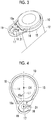
Fig. 3 is a perspective view illustrating a state where a drain hose is inserted to the clip. -
Fig. 4 is a plan view of the clip seen from a rib side. - Hereinafter, an embodiment according to the present invention will be described with reference to the drawings.
-
Fig. 1 illustrates an appearance of an indoor unit 1 for an air conditioning device. The indoor unit 1 is a wall-hanging type, sucks indoor air from above, and blows air after air conditioning indoors from below. The indoor unit 1 is connected to an outdoor unit (not illustrated), receives supply of a refrigerant compressed by the outdoor unit, and adjusts indoor air so as to have a predetermined temperature by means of an indoor heat exchanger provided inside the indoor unit 1. -
Fig. 2 is a partially enlarged view of adrain pan 3 provided in the indoor unit 1. Thedrain pan 3 is provided on a lower side of the indoor unit 1 such that drain water condensed by the indoor heat exchanger is led thereto. A drain socket (drain hose inlet) 5 for discharging the drain water led to thedrain pan 3 to the outside is provided in thedrain pan 3. Thedrain socket 5 has a cylindrical shape, and is provided to protrude from a main body portion of thedrain pan 3. - A screw boss (boss for fastening means) 7, which is a drain pan side fastening portion, is provided on the side of the
drain socket 5. Thescrew boss 7 has a cylindrical shape having a diameter smaller than thedrain socket 5, and is provided to protrude from this end portion of thedrain pan 3. Ascrew hole 7a is formed in the middle of thescrew boss 7. A screw for screwing a clip (drain hose fastener) 10, which is for fastening a drain hose to thedrain socket 5, is inserted to thescrew hole 7a. - The
clip 10 is used in a state where a tip of thedrain hose 12 is inserted as illustrated inFig. 3 . In this state, the tip of thedrain hose 12 is fitted to thedrain socket 5 illustrated inFig. 2 , and then theclip 10 is attached by rotating in an arrow A1 direction. - As illustrated in
Fig. 4 , theclip 10 is made of a resin, and has amain body portion 15 in which a hole portion for adrain hose 14, to which thedrain hose 12 is inserted, is formed and afastening portion 17 which is connected to themain body portion 15 and in which a hole portion for ascrew 16 is formed. - An appearance of the
main body portion 15 is a substantially circular shape in a case of plan view as inFig. 4 . The hole portion for adrain hose 14 that has a center O1, which is common to the substantially circular appearance of the main body portion, is formed. The hole portion for adrain hose 14 has a slightly smaller diameter than an outer diameter of thedrain hose 12, and thedrain hose 12 is fitted thereto in a state of being pressed in. Arib 19 that is erected in a thickness direction (direction perpendicular to the page ofFig. 4 ) is provided along the entire outer peripheral edge of themain body portion 15. - The fastening
portion 17 is integrally formed to be continuous from themain body portion 15 and is formed to protrude to an outer side in a radial direction of the substantially circularmain body portion 15. Therefore, theclip 10 formed with themain body portion 15 and thefastening portion 17 has a teardrop shape of which a part bulges out in a case of plan view as inFig. 4 . - The hole portion for a
screw 16 formed in thefastening portion 17 is a circle of which a center is a center 02, is a through-hole for inserting the screw used when screwing theclip 10 to thescrew boss 7 of the drain pan (refer toFig. 2 ), and has a slightly larger outer diameter than the screw. - The
rib 19 is provided on the periphery of thefastening portion 17. Therib 19 is formed to be continuous from therib 19 provided on themain body portion 15. Aflat portion 21, in which therib 19 is not provided, is provided on one side of thefastening portion 17. Theflat portion 21 is continuous from a flat plate-shaped flat surface (reference surface) P of thefastening portion 17, and has the same height as the flat surface P. - A
positioning rib 19a connected to therib 19 is provided on thefastening portion 17. Thepositioning rib 19a has an inner circumferential surface 19a1 having curvature corresponding to that of a side surface shape of the screw boss 7 (refer toFig. 2 ). A position of the hole portion for ascrew 16 with respect to thescrew boss 7 is accurately determined by a side surface of thescrew boss 7 abutting against the inner circumferential surface 19a1. Thepositioning rib 19a may be provided independently without being connected to therib 19. - The
positioning rib 19a and theflat portion 21 are respectively provided on both sides of a reference line L1 passing through the center O1 of the hole portion for adrain hose 14 and the center 02 of the hole portion for ascrew 16. Accordingly, when rotating theclip 10 about thedrain hose 12, thescrew boss 7 passes through theflat portion 21, and then thescrew boss 7 abuts against thepositioning rib 19a. - Next, a fastening method for the
drain hose 12, in which theaforementioned clip 10 is used, will be described. - First, as illustrated in
Fig. 3 , the tip of thedrain hose 12 is inserted into the hole portion for adrain hose 14 of theclip 10 such that therib 19 of theclip 10 faces the tip of the drain hose 12 (therib 19 faces an upper side inFig. 3 ). - Then, the tip of the
drain hose 12, along with theclip 10, is inserted to thedrain socket 5 illustrated inFig. 2 . At this time, an inner circumference of thedrain hose 12 and an outer circumference of thedrain socket 5 are in close contact with each other. - Next, the
clip 10 is rotated in the arrow A1 direction ofFig. 2 , that is, about a center of thedrain hose 12. At this time, thedrain hose 12 remains substantially stationary with respect to thedrain socket 5, and theclip 10 is displaced with respect to thedrain hose 12. - When the
fastening portion 17 of theclip 10 rotates in the arrow A1 direction, first, theflat portion 21 of the fastening portion 17 (refer toFig. 4 ) passes through the upper side of thescrew boss 7. After then, the inner circumferential surface 19a1 of thepositioning rib 19a abuts against the side surface of thescrew boss 7. Accordingly, theclip 10 is positioned with respect to thescrew boss 7. Then, a screw is screwed by passing the screw through thescrew hole 7a of thescrew boss 7 from the hole portion for ascrew 16 of thefastening portion 17, and thereby theclip 10 is fastened to thescrew boss 7. - As described above, the following operational effects are achieved in the embodiment.
- When fastening the
clip 10, theclip 10 is rotated about the center O1 of the hole portion for adrain hose 14 in a state where thedrain hose 12 is inserted to the hole portion for adrain hose 14, and the hole portion for ascrew 16 is moved to thescrew boss 7. At this time, theflat portion 21 provided on one side of the reference line L1 passing through the center O1 of the hole portion for adrain hose 14 and the center 02 of the hole portion for ascrew 16 is passed, and the hole portion for ascrew 16 is moved to thescrew boss 7. Then, thepositioning rib 19a abuts against thescrew boss 7. Accordingly, the position of the hole portion for ascrew 16 with respect to thescrew hole 7a of thescrew boss 7 can be easily determined, and thereby workability improves. - Since the
rib 19 is provided on the periphery of themain body portion 15 and the periphery of thefastening portion 17, the strength of theclip 10 can be enhanced. -
- 1: indoor unit
- 3: drain pan
- 5: drain socket (drain hose inlet)
- 7: screw boss (boss for fastening means)
- 7a: screw hole
- 10: clip (drain hose fastener)
- 12: drain hose
- 14: hole portion for drain hose
- 15: main body portion
- 16: hole portion for screw (hole portion for fastening means)
- 17: fastening portion
- 19: rib
- 19a: positioning rib
- 19a1: inner circumferential surface
- 21: flat portion
- 01: center (of hole portion for drain hose)
- 02: center (of hole portion for screw)
- P: flat surface (reference surface)
Claims (3)
- A drain hose fastener that fastens a drain hose inserted to a drain hose inlet provided in a drain pan which receives water dropping from a heat exchanger of an air conditioning device, the drain hose fastener comprising:a main body portion in which a hole portion for a drain hose, to which the drain hose is to be inserted, is formed; anda fastening portion which is connected to the main body portion and in which a hole portion for fastening means that allows fastening means fastening the drain hose fastener to a drain pan side fastening portion of the drain pan to pass therethrough is formed,wherein a rib that is erected from a reference surface and a flat portion that has substantially the same height as the reference surface are provided in the fastening portion with a reference line passing through a center of the hole portion for a drain hose and a center of the hole portion for fastening means interposed therebetween.
- The drain hose fastener according to Claim 1,
wherein the rib is provided on a periphery of the main body portion and a periphery of the fastening portion, and is notched at the flat portion. - An indoor unit for an air conditioning device comprising:the drain hose fastener according to Claim 1 or 2;a drain hose to be inserted to the hole portion for a drain hose of the drain hose fastener; anda drain pan in which a drain hose inlet, to which the drain hose is to be inserted, and a boss for fastening means, to which fastening means passing through the hole portion for fastening means is fastened, are provided.
Applications Claiming Priority (2)
| Application Number | Priority Date | Filing Date | Title |
|---|---|---|---|
| JP2017070985A JP6833590B2 (en) | 2017-03-31 | 2017-03-31 | Indoor unit of drain hose fixture and air conditioner |
| PCT/JP2018/008863 WO2018180322A1 (en) | 2017-03-31 | 2018-03-07 | Drain hose fastener, and indoor unit for air conditioning device |
Publications (2)
| Publication Number | Publication Date |
|---|---|
| EP3543620A1 true EP3543620A1 (en) | 2019-09-25 |
| EP3543620A4 EP3543620A4 (en) | 2020-01-01 |
Family
ID=63675477
Family Applications (1)
| Application Number | Title | Priority Date | Filing Date |
|---|---|---|---|
| EP18778234.7A Withdrawn EP3543620A4 (en) | 2017-03-31 | 2018-03-07 | Drain hose fastener, and indoor unit for air conditioning device |
Country Status (4)
| Country | Link |
|---|---|
| EP (1) | EP3543620A4 (en) |
| JP (1) | JP6833590B2 (en) |
| AU (1) | AU2018245360B2 (en) |
| WO (1) | WO2018180322A1 (en) |
Cited By (1)
| Publication number | Priority date | Publication date | Assignee | Title |
|---|---|---|---|---|
| EP4239257A4 (en) * | 2020-10-27 | 2024-07-17 | Toshiba Carrier Corporation | Indoor unit for air conditioner |
Families Citing this family (1)
| Publication number | Priority date | Publication date | Assignee | Title |
|---|---|---|---|---|
| JP6998276B2 (en) * | 2018-06-01 | 2022-01-18 | 株式会社コロナ | Air conditioner |
Family Cites Families (8)
| Publication number | Priority date | Publication date | Assignee | Title |
|---|---|---|---|---|
| US2904294A (en) * | 1957-02-11 | 1959-09-15 | Northrop Corp | Clamp device |
| US4805856A (en) * | 1987-12-29 | 1989-02-21 | Panduit Corp. | Cable mount |
| JP4507568B2 (en) * | 2003-11-19 | 2010-07-21 | パナソニック株式会社 | Hose attachment device |
| JP4557150B2 (en) * | 2004-11-16 | 2010-10-06 | 株式会社富士通ゼネラル | Air conditioner |
| JP4614781B2 (en) * | 2005-01-26 | 2011-01-19 | 三洋電機株式会社 | Air conditioner |
| JP2006242434A (en) * | 2005-03-02 | 2006-09-14 | Sharp Corp | Drain drainage pipe fixing structure |
| JP5278341B2 (en) * | 2010-01-21 | 2013-09-04 | ダイキン工業株式会社 | Air conditioning indoor unit |
| DE102015008350A1 (en) * | 2015-06-27 | 2016-12-29 | Man Truck & Bus Ag | Holding device for holding a motor vehicle exhaust pipe |
-
2017
- 2017-03-31 JP JP2017070985A patent/JP6833590B2/en active Active
-
2018
- 2018-03-07 WO PCT/JP2018/008863 patent/WO2018180322A1/en not_active Ceased
- 2018-03-07 AU AU2018245360A patent/AU2018245360B2/en active Active
- 2018-03-07 EP EP18778234.7A patent/EP3543620A4/en not_active Withdrawn
Cited By (1)
| Publication number | Priority date | Publication date | Assignee | Title |
|---|---|---|---|---|
| EP4239257A4 (en) * | 2020-10-27 | 2024-07-17 | Toshiba Carrier Corporation | Indoor unit for air conditioner |
Also Published As
| Publication number | Publication date |
|---|---|
| WO2018180322A1 (en) | 2018-10-04 |
| JP6833590B2 (en) | 2021-02-24 |
| AU2018245360A1 (en) | 2019-07-11 |
| AU2018245360B2 (en) | 2020-04-30 |
| EP3543620A4 (en) | 2020-01-01 |
| JP2018173215A (en) | 2018-11-08 |
Similar Documents
| Publication | Publication Date | Title |
|---|---|---|
| EP2489947A1 (en) | Structure and method for connecting refrigerant pipe and air conditioner having the same structure | |
| JP3144918U (en) | Drain hose fittings for air conditioning indoor units | |
| AU2018245360B2 (en) | Drain hose fastener, and indoor unit for air conditioning device | |
| EP2589833A2 (en) | Damper for decreasing a pipe vibration | |
| US20180135779A1 (en) | Pipe securing apparatus | |
| US9903600B2 (en) | Wind direction adjusting device of air-conditioning apparatus and air-conditioning apparatus | |
| US20150176856A1 (en) | Indoor unit and air-conditioning apparatus | |
| US8944397B2 (en) | Universal HVAC component mounting systems | |
| US20160341082A1 (en) | Blow-by heater | |
| US11662160B2 (en) | Collector tube for a heat exchanger | |
| KR100786686B1 (en) | Piping holder and air conditioner with same | |
| CN211177148U (en) | Mobile air conditioner | |
| JP2016023873A (en) | Air conditioner indoor unit | |
| CN105065786A (en) | Vibration reduction rubber ring structure and air conditioner with same | |
| KR101715867B1 (en) | Air Duct Connector | |
| EP2916084A1 (en) | Integrated air conditioner | |
| JP3915803B2 (en) | Air supply / exhaust port | |
| CN116264379A (en) | connector | |
| US20220090818A1 (en) | Indoor unit of air-conditioning apparatus and air-conditioning apparatus | |
| CN205227709U (en) | A air conditioner that is used for pipeline subassembly of air conditioner and has it | |
| CN203857581U (en) | Air conditioner | |
| EP2253907A2 (en) | Condensing unit attachment feature | |
| CN206291429U (en) | A kind of fixed structure of handle | |
| KR0130392B1 (en) | Establishing apparatus for discharge grill of out-door units of separate airconditioner | |
| CN205155137U (en) | Sealing structure and damper assembly |
Legal Events
| Date | Code | Title | Description |
|---|---|---|---|
| PUAI | Public reference made under article 153(3) epc to a published international application that has entered the european phase |
Free format text: ORIGINAL CODE: 0009012 |
|
| 17P | Request for examination filed |
Effective date: 20190621 |
|
| AK | Designated contracting states |
Kind code of ref document: A1 Designated state(s): AL AT BE BG CH CY CZ DE DK EE ES FI FR GB GR HR HU IE IS IT LI LT LU LV MC MK MT NL NO PL PT RO RS SE SI SK SM TR |
|
| AX | Request for extension of the european patent |
Extension state: BA ME |
|
| A4 | Supplementary search report drawn up and despatched |
Effective date: 20191202 |
|
| RIC1 | Information provided on ipc code assigned before grant |
Ipc: F16L 3/08 20060101ALI20191126BHEP Ipc: F16L 3/123 20060101ALI20191126BHEP Ipc: F16L 3/12 20060101ALI20191126BHEP Ipc: F24F 13/22 20060101AFI20191126BHEP |
|
| STAA | Information on the status of an ep patent application or granted ep patent |
Free format text: STATUS: THE APPLICATION HAS BEEN WITHDRAWN |
|
| 18W | Application withdrawn |
Effective date: 20200128 |