EP3543567B1 - Two-way mechanical seal - Google Patents
Two-way mechanical seal Download PDFInfo
- Publication number
- EP3543567B1 EP3543567B1 EP17871649.4A EP17871649A EP3543567B1 EP 3543567 B1 EP3543567 B1 EP 3543567B1 EP 17871649 A EP17871649 A EP 17871649A EP 3543567 B1 EP3543567 B1 EP 3543567B1
- Authority
- EP
- European Patent Office
- Prior art keywords
- mechanical seal
- elastomeric
- seal
- bidirectional sealing
- sealing according
- Prior art date
- Legal status (The legal status is an assumption and is not a legal conclusion. Google has not performed a legal analysis and makes no representation as to the accuracy of the status listed.)
- Active
Links
Images

Classifications
-
- F—MECHANICAL ENGINEERING; LIGHTING; HEATING; WEAPONS; BLASTING
- F16—ENGINEERING ELEMENTS AND UNITS; GENERAL MEASURES FOR PRODUCING AND MAINTAINING EFFECTIVE FUNCTIONING OF MACHINES OR INSTALLATIONS; THERMAL INSULATION IN GENERAL
- F16J—PISTONS; CYLINDERS; SEALINGS
- F16J15/00—Sealings
- F16J15/16—Sealings between relatively-moving surfaces
- F16J15/34—Sealings between relatively-moving surfaces with slip-ring pressed against a more or less radial face on one member
- F16J15/3496—Sealings between relatively-moving surfaces with slip-ring pressed against a more or less radial face on one member use of special materials
Definitions
- the present invention relates to a mechanical seal for bidirectional sealing, which comprises a combination of elastomer and composite material to resist extrusion failure under large dimensional clearance conditions.
- the mechanical seal object of the present invention may be used in any mechanical system where it is necessary to separate two regions with differential pressures ranging from low to high pressures.
- the mechanical seal of the present invention is especially suitable for use in underwater or ground equipment requiring the presence of elastomeric seals.
- elastomeric seals which may or may not include reinforcements.
- reinforcements may be obtained either by the addition of other materials to the elastomeric compound or by using one or more additional parts to the elastomeric seal, said parts being metallic, ceramic, polymeric or any other material with several geometries, in order to reinforce the seal and withstand higher differential pressures.
- seals In addition to the variety of material types, there are several elastomeric seal geometries in order to reinforce their structure in a way to withstand higher pressure differentials. Examples of these seals are: O-ring, spring seal and lip seal. These seals have a very efficient behavior and are widely used for the sealing of several components, such as mechanical connectors, flanges, stabs, etc.
- seals are dependent on small dimensional tolerances, in the order of tenths of a millimeter diametrically, which are fundamental to ensure correct preloading and resistance to extrusion of the elastomeric material when subjected to a differential pressure. When these thresholds are exceeded, an elastomer extrusion occurs and the consequent unfeasibility of the seal.
- elastomeric seals are classified into three groups: elastomeric seals with a single material, for example O-rings; bicomponent elastomeric seals, for example elastomeric ring combined with anti-extrusion ring; and elastomeric seals with more than one material in a single component, for example the lip seal, spring seal.
- Single-material elastomeric seals have very limited extrusion strength and are suitable for working with small dimensional tolerances, since they do not have any special anti-extrusion mechanism.
- the hardening of the elastomer as a mitigating action to avoid extrusion failure compromises the ability to deform at low pressures and to promote sealing. Historically, such seals even in restricted dimensional tolerances do not withstand differential pressures greater than 344,7 bar (5.000 psi).
- Bicomponent seals have superior sealing strength at larger clearances and higher pressures.
- the use of a second anti-extrusion component in addition to having assembly limitations does not allow for clearance of the order of a few millimeters, since many of them are made of polymeric materials.
- seals with more than one material fill a space by combining rubber with other materials.
- seals have high restrictions on assembly in external and internal diameters due to the restriction imposed by using more resistant materials.
- metallic materials these can damage the sealing areas in case of dynamic applications.
- the operating mechanism of these sealing rings seeks a balance between the seal material elastic deformation, which is important for sealing, the small dimensional component clearances which is important for extrusion strength, and elastic deformation required for assembling in several diameters.
- US 6123337 A shows a high performance rock bit journal seal formed from a composite material comprising an elastomeric material and a nonelastomeric polymeric material.
- the polymeric material is preferably in the form of fibers compiled or woven into a sheet.
- the elastomeric material may include one or more lubricant additives.
- the composite seal material comprises a number of repeating sheets of polymeric fabric that are bonded together with the elastomeric material.
- the seal can either be formed entirely of the composite seal material or partially of the composite material, in which case it is preferred that the seal wear or dynamic surface be formed from the composite material and the remaining portion of the seal be formed from an elastomeric material.
- US 20110140369 A1 shows a seal which comprises a metal spring bonded to an elastomer body that is coupled to a polymer ring.
- the spring may comprise a cantilevered, overlapped metal strip.
- the elastomer and polymer mechanically interlock with radial members.
- the elastomer has contacting surfaces configured in outward extending radii to enhance forward edge loading and oil removal from the dynamic surface. In hydraulic service, the seal prevents the egress of hydraulic fluid and ingress of foreign particles.
- US 6302405 B1 shows a seal assembly formed of a T-seal, a pair of back-up rings abutting each side of the T-seal, and a bearing abutting the side of each of the back-up rings.
- the T-seal is formed of a elastomer material
- the back-up ring is formed of a PTFE (polytetraflouroethylene polymer) material
- the bearings are formed of a carbon reinforced PEEK (polyetheretherketone) material.
- the above mentioned mechanical seals have as main limitations the combination of certain factors, such as, for example, the dimensional clearances necessary to avoid extrusion failure of the elastomeric material, typically limited to a maximum of tenths of a millimeter, and the ability to deform for assembly in machined housings at external and internal diameters, restricting the options of reinforcements, which, because they are required to accept high elastic deformation, do not present high mechanical strength to withstand pressure differentials in
- the present invention therefore provides for the correction of the above problems for the mechanical seals of the prior art, which will evidently result in a significant increase in efficiency in relation to the sealing and anti-extrusion due to the pressure differential, effects of which have long been searched by those skilled in the art.
- the bicomponent mechanical seal object of the present invention comprises an elastomeric ring with a reinforcement of segmented and lagged composite material. Unlike prior art seals, such segmented bicomponent seal reinforcements of the invention facilitate assembly in machined housings.
- the mechanical seal for bidirectional sealing of the present invention has been designed for use in static and/or dynamic applications in submarine and ground equipment to effect diametrical seals with process fluid, oil or gas or a combination of both.
- the mechanical seal for bidirectional sealing of the present invention may be used for low pressure seals, for example, less than 20,7 bar (300 psi) or for high pressure seals, which may reach, for example, 2068,4 bar (30.000 psi) or more.
- the bidirectional seal according to the present invention has a body (1) in a hybrid material (elastomer + composite), being structured in an elastomeric material component (2) and a segmented composite material component (3).
- a hybrid material elastomer + composite
- the elastomeric material component (2) preferably has properties of an amorphous material, i.e., it does not have an ordered polymer chain, and has a high elasticity. Therefore, the elastomeric component (2) may deform when subjected to high differential pressure and return to its original shape after the said pressure has stopped.
- the elastomeric component (2) of the mechanical seal for bidirectional sealing according to the present invention may be made of any material, such as NBR, HNBR, FKM, FFKM or any other material with suitable elastomeric property.
- the elastomer type is defined by the differential pressure regime in which the seal of the present invention will work and the environment type (fluids and gases) it is expected to withstand.
- the profile of the elastomeric component (2) is not limited to that shown in Figure 2 , so that it may range depending on the housing shape in the part where it will be installed as well as the pressure class of the seal.
- the mechanical seal for bidirectional sealing of the present invention is a hybrid material having at least two components in its physical structure and clearly distinct, an elastomeric component (2) and a segmented reinforcement (3) being continuous fibers dispersed in a polymer matrix, such as for example glass, carbon or aramid fiber, among others.
- a polymer matrix such as for example glass, carbon or aramid fiber, among others.
- substituted continuous fibers may be produced in other materials, such as metals or metal alloys, among others, depending on the specific application.
- the sealing efficiency for high clearances is due to the elastomer assembly and composite reinforcement, since the reinforcement is intended to prevent the extrusion of the elastomer caused by the clearance and the differential pressure.
- the segmentation of this reinforcement has the function of facilitating the seal assembly, expanding its application in function of the dimensional variables and rigidity of the elastomer. Therefore, segmented reinforcement is important in preventing elastomer extrusion seal failure.
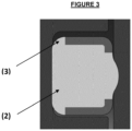
- segmented reinforcement (3) will depend on the profile of the elastomeric component (2), which may range according to the application of the mechanical seal for bidirectional sealing of the present invention, as can be seen in Figure 3 .
- the geometry of the mechanical seal for bidirectional sealing of the present invention allows to facilitate assembly in machined housings in diameters due to the use of the combined segmented inserts/reinforcements.
- the segmentation of the reinforcements in composite material is performed in a lagged manner, as highlighted in detail (4), as a fundamental characteristic to minimize the extrusion failure, since it prevents the existence of a continuous section of only elastomeric material.
- the lagging of the reinforcements is important because, for configurations with segmented inserts, the transition between two inserts necessarily exposes an area composed only of rubber, which implies in the concentration of pressure in this area and due to its lower mechanical resistance, implies in a higher possibility of extrusion failure.
- the lagging of the segments prevents the existence of a continuous section of elastomeric material and therefore always adds a mechanical resistance barrier (insert) in the fragile regions.
- the present invention has the apparent advantages of rendering the mechanical seal for bidirectional sealing resistant to extrusion failure for components having high radial clearance, of the order of 3,0 mm or more, combined with high differential pressures, typically ranging from 344,7 bar to 1379 bar (5.000 to 20.000 psi) or more.
Landscapes
- Engineering & Computer Science (AREA)
- General Engineering & Computer Science (AREA)
- Mechanical Engineering (AREA)
- Gasket Seals (AREA)
- Sealing Devices (AREA)
Description
- The present invention relates to a mechanical seal for bidirectional sealing, which comprises a combination of elastomer and composite material to resist extrusion failure under large dimensional clearance conditions. The mechanical seal object of the present invention may be used in any mechanical system where it is necessary to separate two regions with differential pressures ranging from low to high pressures. Thus, the mechanical seal of the present invention is especially suitable for use in underwater or ground equipment requiring the presence of elastomeric seals.
- As is well known in the art, the mechanical seal was developed by George Cook in the early 20th century, originally called "Cook Seal", and was applied in cooling compressors. Since then there have been improvements due to the demand for seals working at different pressure levels and different mechanisms. Due to this fact, several materials are until now studied and applied to obtain increasingly better results for this mechanical element.
- In the oil and gas sector, several types of elastomeric seals are used, which may or may not include reinforcements. Such reinforcements may be obtained either by the addition of other materials to the elastomeric compound or by using one or more additional parts to the elastomeric seal, said parts being metallic, ceramic, polymeric or any other material with several geometries, in order to reinforce the seal and withstand higher differential pressures.
- In addition to the variety of material types, there are several elastomeric seal geometries in order to reinforce their structure in a way to withstand higher pressure differentials. Examples of these seals are: O-ring, spring seal and lip seal. These seals have a very efficient behavior and are widely used for the sealing of several components, such as mechanical connectors, flanges, stabs, etc.
- These seals are dependent on small dimensional tolerances, in the order of tenths of a millimeter diametrically, which are fundamental to ensure correct preloading and resistance to extrusion of the elastomeric material when subjected to a differential pressure. When these thresholds are exceeded, an elastomer extrusion occurs and the consequent unfeasibility of the seal.
- Current elastomeric seals are classified into three groups: elastomeric seals with a single material, for example O-rings; bicomponent elastomeric seals, for example elastomeric ring combined with anti-extrusion ring; and elastomeric seals with more than one material in a single component, for example the lip seal, spring seal.
- Single-material elastomeric seals have very limited extrusion strength and are suitable for working with small dimensional tolerances, since they do not have any special anti-extrusion mechanism. The hardening of the elastomer as a mitigating action to avoid extrusion failure compromises the ability to deform at low pressures and to promote sealing. Historically, such seals even in restricted dimensional tolerances do not withstand differential pressures greater than 344,7 bar (5.000 psi).
- Bicomponent seals, on the other hand, have superior sealing strength at larger clearances and higher pressures. However, the use of a second anti-extrusion component in addition to having assembly limitations does not allow for clearance of the order of a few millimeters, since many of them are made of polymeric materials. Other materials, for example metallic, in turn, compromise the assembly and its dynamic applications due to the risk of scratching the sealing areas.
- Finally, seals with more than one material fill a space by combining rubber with other materials. However, such seals have high restrictions on assembly in external and internal diameters due to the restriction imposed by using more resistant materials. In the case of metallic materials, these can damage the sealing areas in case of dynamic applications. In all current systems, the operating mechanism of these sealing rings seeks a balance between the seal material elastic deformation, which is important for sealing, the small dimensional component clearances which is important for extrusion strength, and elastic deformation required for assembling in several diameters.
-
US2015233371 ,US2005167928 andUS5791657 disclose mechanical seals of the closest prior art to the present invention as they disclose seals which have sealing and anti-extrusion elements. However, the combination of high dimensional clearance, assembly and high differential pressure cannot be supported by existing elastomeric seals, whether with or without reinforcements. -
US 6123337 A ,US 20110140369 A1 andUS 6302405 B1 show other prior art and in particular:US 6123337 A shows a high performance rock bit journal seal formed from a composite material comprising an elastomeric material and a nonelastomeric polymeric material. The polymeric material is preferably in the form of fibers compiled or woven into a sheet. The elastomeric material may include one or more lubricant additives. The composite seal material comprises a number of repeating sheets of polymeric fabric that are bonded together with the elastomeric material. The seal can either be formed entirely of the composite seal material or partially of the composite material, in which case it is preferred that the seal wear or dynamic surface be formed from the composite material and the remaining portion of the seal be formed from an elastomeric material..US 20110140369 A1 shows a seal which comprises a metal spring bonded to an elastomer body that is coupled to a polymer ring. The spring may comprise a cantilevered, overlapped metal strip. The elastomer and polymer mechanically interlock with radial members. The elastomer has contacting surfaces configured in outward extending radii to enhance forward edge loading and oil removal from the dynamic surface. In hydraulic service, the seal prevents the egress of hydraulic fluid and ingress of foreign particles.US 6302405 B1 shows a seal assembly formed of a T-seal, a pair of back-up rings abutting each side of the T-seal, and a bearing abutting the side of each of the back-up rings. The T-seal is formed of a elastomer material, the back-up ring is formed of a PTFE (polytetraflouroethylene polymer) material, and the bearings are formed of a carbon reinforced PEEK (polyetheretherketone) material.The above mentioned mechanical seals have as main limitations the combination of certain factors, such as, for example, the dimensional clearances necessary to avoid extrusion failure of the elastomeric material, typically limited to a maximum of tenths of a millimeter, and the ability to deform for assembly in machined housings at external and internal diameters, restricting the options of reinforcements, which, because they are required to accept high elastic deformation, do not present high mechanical strength to withstand pressure differentials in the order of tens of thousands of psi, for example 1379 bar (20.000 psi). - The present invention therefore provides for the correction of the above problems for the mechanical seals of the prior art, which will evidently result in a significant increase in efficiency in relation to the sealing and anti-extrusion due to the pressure differential, effects of which have long been searched by those skilled in the art.
- It is therefore the object of the present invention to provide a bicomponent mechanical seal which supports larger differential pressures and diametrical clearances with no failure of elastomer extrusion seal, and which also ensures a low-pressure seal.
- The bicomponent mechanical seal object of the present invention comprises an elastomeric ring with a reinforcement of segmented and lagged composite material. Unlike prior art seals, such segmented bicomponent seal reinforcements of the invention facilitate assembly in machined housings.
- The mechanical seal according to the present invention may be better understood in its structure, function and effects from the accompanying schematic figures which, by way of non-limiting scope, represent:
-
Figure 1 - a top view of a mechanical seal for bidirectional sealing according to the present invention; -
Figure 2 - a partial cross-section perspective view of the mechanical seal for bidirectional sealing according to the present invention; -
Figure 3 - a cross-sectional view of the mechanical seal for bidirectional sealing according to the present invention. - The mechanical seal for bidirectional sealing of the present invention has been designed for use in static and/or dynamic applications in submarine and ground equipment to effect diametrical seals with process fluid, oil or gas or a combination of both. Thus, the mechanical seal for bidirectional sealing of the present invention may be used for low pressure seals, for example, less than 20,7 bar (300 psi) or for high pressure seals, which may reach, for example, 2068,4 bar (30.000 psi) or more.
- The bidirectional seal according to the present invention, as seen in
Figures 1, 2 , and3 , has a body (1) in a hybrid material (elastomer + composite), being structured in an elastomeric material component (2) and a segmented composite material component (3). - An example of an arrangement in which the seal is composed is shown in
Figure 2 , where the elastomeric material component (2) preferably has properties of an amorphous material, i.e., it does not have an ordered polymer chain, and has a high elasticity. Therefore, the elastomeric component (2) may deform when subjected to high differential pressure and return to its original shape after the said pressure has stopped. - The elastomeric component (2) of the mechanical seal for bidirectional sealing according to the present invention may be made of any material, such as NBR, HNBR, FKM, FFKM or any other material with suitable elastomeric property. Obviously, the elastomer type is defined by the differential pressure regime in which the seal of the present invention will work and the environment type (fluids and gases) it is expected to withstand.
- The profile of the elastomeric component (2) is not limited to that shown in
Figure 2 , so that it may range depending on the housing shape in the part where it will be installed as well as the pressure class of the seal. - The mechanical seal for bidirectional sealing of the present invention is a hybrid material having at least two components in its physical structure and clearly distinct, an elastomeric component (2) and a segmented reinforcement (3) being continuous fibers dispersed in a polymer matrix, such as for example glass, carbon or aramid fiber, among others. However, it should be noted that such substituted continuous fibers may be produced in other materials, such as metals or metal alloys, among others, depending on the specific application.
- The sealing efficiency for high clearances is due to the elastomer assembly and composite reinforcement, since the reinforcement is intended to prevent the extrusion of the elastomer caused by the clearance and the differential pressure. The segmentation of this reinforcement has the function of facilitating the seal assembly, expanding its application in function of the dimensional variables and rigidity of the elastomer. Therefore, segmented reinforcement is important in preventing elastomer extrusion seal failure.
- Another aspect to be observed is the fact that the profile of the segmented reinforcement (3) will depend on the profile of the elastomeric component (2), which may range according to the application of the mechanical seal for bidirectional sealing of the present invention, as can be seen in
Figure 3 . - The geometry of the mechanical seal for bidirectional sealing of the present invention allows to facilitate assembly in machined housings in diameters due to the use of the combined segmented inserts/reinforcements. The segmentation of the reinforcements in composite material is performed in a lagged manner, as highlighted in detail (4), as a fundamental characteristic to minimize the extrusion failure, since it prevents the existence of a continuous section of only elastomeric material.
- The lagging of the reinforcements is important because, for configurations with segmented inserts, the transition between two inserts necessarily exposes an area composed only of rubber, which implies in the concentration of pressure in this area and due to its lower mechanical resistance, implies in a higher possibility of extrusion failure. The lagging of the segments prevents the existence of a continuous section of elastomeric material and therefore always adds a mechanical resistance barrier (insert) in the fragile regions.
- The present invention has the apparent advantages of rendering the mechanical seal for bidirectional sealing resistant to extrusion failure for components having high radial clearance, of the order of 3,0 mm or more, combined with high differential pressures, typically ranging from 344,7 bar to 1379 bar (5.000 to 20.000 psi) or more.
Claims (8)
- Mechanical seal for bidirectional sealing, comprising a body (1) in hybrid material being structured in a component of ring-shaped elastomeric material (2), and characterized in that it is further structured in a component of reinforcement of segmented and lagged composite material (3), the composite material (3) being distributed in a lagged way (4) along an outer surface of said body (1), wherein the lagged composite material (3) prevents the formation of a continuous section of the elastomeric material (2).
- Mechanical seal for bidirectional sealing according to claim 1, characterized in that the elastomeric component (2) is a high elastic amorphous material or any other elastomeric material.
- Mechanical seal for bidirectional sealing according to claim 2, characterized in that the elastomeric component (2) is made of NBR, HNBR, FKM, FFKM or any other material.
- Mechanical seal for bidirectional sealing according to claim 1, characterized in that the elastomeric component (2) is shaped according to the housing in the part where it will be installed.
- Mechanical seal for bidirectional sealing according to claim 1, characterized in that the segmented reinforcement (3) is produced by the dispersion of continuous fibers in a polymeric matrix.
- Mechanical seal for bidirectional sealing according to claim 5, characterized in that the segmented reinforcement (3) is produced in glass fiber, carbon fiber, aramid fiber or any other material.
- Mechanical seal for bidirectional sealing according to claim 1, characterized in that the segmented reinforcement (3) can also be produced in metal or metal alloys.
- Mechanical seal for bidirectional sealing according to any of the previous claims, characterized in that it is resistant to extrusion failure for components with radial clearance of the order of at least 3,0 mm combined with high differential pressures typically ranging from at least 344,7 bar (5.000 psi) to 1379 bar (20.000 psi).
Applications Claiming Priority (2)
| Application Number | Priority Date | Filing Date | Title |
|---|---|---|---|
| BR102016027258-0A BR102016027258B1 (en) | 2016-11-21 | 2016-11-21 | MECHANICAL SEAL FOR BIDIRECTIONAL SEALING |
| PCT/BR2017/050348 WO2018090120A1 (en) | 2016-11-21 | 2017-11-17 | Two-way mechanical seal |
Publications (3)
| Publication Number | Publication Date |
|---|---|
| EP3543567A1 EP3543567A1 (en) | 2019-09-25 |
| EP3543567A4 EP3543567A4 (en) | 2020-07-15 |
| EP3543567B1 true EP3543567B1 (en) | 2024-10-16 |
Family
ID=62145974
Family Applications (1)
| Application Number | Title | Priority Date | Filing Date |
|---|---|---|---|
| EP17871649.4A Active EP3543567B1 (en) | 2016-11-21 | 2017-11-17 | Two-way mechanical seal |
Country Status (4)
| Country | Link |
|---|---|
| US (1) | US11274748B2 (en) |
| EP (1) | EP3543567B1 (en) |
| BR (1) | BR102016027258B1 (en) |
| WO (1) | WO2018090120A1 (en) |
Families Citing this family (1)
| Publication number | Priority date | Publication date | Assignee | Title |
|---|---|---|---|---|
| US12435661B1 (en) * | 2024-04-08 | 2025-10-07 | Pratt & Whitney Canada Corp. | Rotary engine with seal having shield and elastomeric member |
Family Cites Families (19)
| Publication number | Priority date | Publication date | Assignee | Title |
|---|---|---|---|---|
| US3582094A (en) * | 1970-02-16 | 1971-06-01 | Greene Tweed & Co Inc | Sealing assembly |
| US4032159A (en) * | 1975-10-28 | 1977-06-28 | Poly Seal, Inc. | Interference compression seal |
| US4212477A (en) * | 1976-03-21 | 1980-07-15 | The United States Of America As Represented By The Administrator Of The National Aeronautics And Space Administration | Circumferential shaft seal |
| US5163692A (en) | 1989-07-24 | 1992-11-17 | Furon Company | One-piece composite lip seal |
| GB2287734B (en) | 1994-03-22 | 1997-10-01 | Fmc Corp | Seals containing non-metallic springs |
| US5738358A (en) | 1996-01-02 | 1998-04-14 | Kalsi Engineering, Inc. | Extrusion resistant hydrodynamically lubricated multiple modulus rotary shaft seal |
| US5842700A (en) * | 1996-10-08 | 1998-12-01 | Smith International, Inc. | Composite rock bit seal |
| US6039319A (en) * | 1997-02-24 | 2000-03-21 | Swagelok Company | Hygienic fitting with thermal expansion area for gasket |
| CA2249916A1 (en) * | 1998-03-11 | 1999-09-11 | Freudenberg-Nok General Partnership | Polytetrafluoroethylene and elastomer seal |
| US6173964B1 (en) * | 1998-07-07 | 2001-01-16 | Greene, Tweed Of Delaware, Inc. | Seal assembly with backup elements having coil springs positioned therein |
| US6302405B1 (en) * | 1999-06-24 | 2001-10-16 | Schlumberger Technology Corporation | Anti-extrusion seal |
| US20050167928A1 (en) | 2004-02-04 | 2005-08-04 | Park Edward H. | Dynamic seal using vulcanization of fluorocarbon elastomers |
| US8550467B2 (en) | 2006-03-22 | 2013-10-08 | Kalsi Engineering, Inc. | Rotary seal with improved film distribution |
| US20090189354A1 (en) | 2008-01-25 | 2009-07-30 | Harvey Lee L | Reciprocating-rod seal |
| CA2781719A1 (en) * | 2009-12-11 | 2011-06-16 | Saint-Gobain Performance Plastics Corporation | System, method and apparatus for spring-energized dynamic sealing assembly |
| DE102013110484A1 (en) * | 2013-09-23 | 2015-03-26 | Deutsches Zentrum für Luft- und Raumfahrt e.V. | Load-adaptive sealing ring, especially for radial shafts |
| WO2016019110A2 (en) * | 2014-08-01 | 2016-02-04 | Utex Industries, Inc. | High pressure seal with composite anti-extrusion mechanism |
| US9939067B2 (en) * | 2015-12-07 | 2018-04-10 | Robert Janian | Elastic contact seal |
| CN106812944A (en) * | 2017-03-28 | 2017-06-09 | 咸阳海龙密封复合材料有限公司 | Embedded with spring rotary shaft lip-shaped sealed ring |
-
2016
- 2016-11-21 BR BR102016027258-0A patent/BR102016027258B1/en active IP Right Grant
-
2017
- 2017-11-17 US US16/462,816 patent/US11274748B2/en active Active
- 2017-11-17 WO PCT/BR2017/050348 patent/WO2018090120A1/en not_active Ceased
- 2017-11-17 EP EP17871649.4A patent/EP3543567B1/en active Active
Also Published As
| Publication number | Publication date |
|---|---|
| EP3543567A1 (en) | 2019-09-25 |
| BR102016027258A2 (en) | 2018-06-12 |
| EP3543567A4 (en) | 2020-07-15 |
| WO2018090120A1 (en) | 2018-05-24 |
| BR102016027258A8 (en) | 2018-06-26 |
| US20210033196A1 (en) | 2021-02-04 |
| US11274748B2 (en) | 2022-03-15 |
| BR102016027258B1 (en) | 2023-02-14 |
Similar Documents
| Publication | Publication Date | Title |
|---|---|---|
| EP1794482B1 (en) | Cammed seal assembly with elastomeric energizer element | |
| CA2730409C (en) | Composite metallic elastomeric sealing components for roller cone drill bits | |
| US9803752B2 (en) | Seal assembly | |
| US9234591B2 (en) | High pressure lip seals with anti-extrusion and anti-galling properties and related methods | |
| US9759334B2 (en) | Gate valve arrangement including multi-valve stem and seat assemblies | |
| EP2385278B1 (en) | Low breakout friction energized gasket | |
| KR102832620B1 (en) | Sealing assembly for ball valve and ball valve including sealing assembly | |
| US9933071B2 (en) | Seal and method of manufacturing and/or using same | |
| US20060145426A1 (en) | Rotary seal | |
| KR20080038039A (en) | Improved fluid actuator for application in turbomachines | |
| US6234540B1 (en) | Sealing arrangement | |
| AU2020202496B2 (en) | Annular sealing assembly | |
| EP0086561B1 (en) | Mechanical seal assembly | |
| US11300208B2 (en) | Seal assembly with anti-rotation and stability features | |
| US11274748B2 (en) | Mechanical seal for bidirectional sealing | |
| US10995863B2 (en) | Dual face-type seat seal arrangement for valve applications | |
| CN110425284B (en) | Sealing element | |
| Dietle et al. | High pressure rotary shaft sealing mechanism |
Legal Events
| Date | Code | Title | Description |
|---|---|---|---|
| STAA | Information on the status of an ep patent application or granted ep patent |
Free format text: STATUS: THE INTERNATIONAL PUBLICATION HAS BEEN MADE |
|
| PUAI | Public reference made under article 153(3) epc to a published international application that has entered the european phase |
Free format text: ORIGINAL CODE: 0009012 |
|
| STAA | Information on the status of an ep patent application or granted ep patent |
Free format text: STATUS: REQUEST FOR EXAMINATION WAS MADE |
|
| 17P | Request for examination filed |
Effective date: 20190529 |
|
| AK | Designated contracting states |
Kind code of ref document: A1 Designated state(s): AL AT BE BG CH CY CZ DE DK EE ES FI FR GB GR HR HU IE IS IT LI LT LU LV MC MK MT NL NO PL PT RO RS SE SI SK SM TR |
|
| AX | Request for extension of the european patent |
Extension state: BA ME |
|
| DAV | Request for validation of the european patent (deleted) | ||
| DAX | Request for extension of the european patent (deleted) | ||
| A4 | Supplementary search report drawn up and despatched |
Effective date: 20200617 |
|
| RIC1 | Information provided on ipc code assigned before grant |
Ipc: F16J 15/32 20160101AFI20200610BHEP Ipc: F16J 15/34 20060101ALI20200610BHEP Ipc: F16J 15/16 20060101ALI20200610BHEP |
|
| RIN1 | Information on inventor provided before grant (corrected) |
Inventor name: NASCIMENTO POMBO DO AMARAL, RICARDO Inventor name: DO CANTO VISENTIN, LORENZO Inventor name: DA SILVA, RONALDO PEDRO Inventor name: CASTANHEIRA FRANCIS CHEHUAN, THIAGO SIMOES Inventor name: LE BOURLEGAT, LOIC RENE Inventor name: DA SILVA, SANDRO EUGENIO Inventor name: ANDUEZA, ALEJANDRO |
|
| STAA | Information on the status of an ep patent application or granted ep patent |
Free format text: STATUS: EXAMINATION IS IN PROGRESS |
|
| 17Q | First examination report despatched |
Effective date: 20220315 |
|
| GRAP | Despatch of communication of intention to grant a patent |
Free format text: ORIGINAL CODE: EPIDOSNIGR1 |
|
| STAA | Information on the status of an ep patent application or granted ep patent |
Free format text: STATUS: GRANT OF PATENT IS INTENDED |
|
| INTG | Intention to grant announced |
Effective date: 20240625 |
|
| RAP1 | Party data changed (applicant data changed or rights of an application transferred) |
Owner name: NANOBUSINESS INFORMACAO E INOVACAO LTDA. Owner name: FMC TECHNOLOGIES DO BRASIL LTDA |
|
| RIN1 | Information on inventor provided before grant (corrected) |
Inventor name: NASCIMENTO POMBO DO AMARAL, RICARDO Inventor name: DO CANTO VISENTIN, LORENZO Inventor name: DA SILVA, RONALDO PEDRO Inventor name: CASTANHEIRA FRANCIS CHEHUAN, THIAGO SIMOES Inventor name: LE BOURLEGAT, LOIC RENE Inventor name: DA SILVA, SANDRO EUGENIO Inventor name: ANDUEZA, ALEJANDRO |
|
| GRAS | Grant fee paid |
Free format text: ORIGINAL CODE: EPIDOSNIGR3 |
|
| GRAA | (expected) grant |
Free format text: ORIGINAL CODE: 0009210 |
|
| STAA | Information on the status of an ep patent application or granted ep patent |
Free format text: STATUS: THE PATENT HAS BEEN GRANTED |
|
| AK | Designated contracting states |
Kind code of ref document: B1 Designated state(s): AL AT BE BG CH CY CZ DE DK EE ES FI FR GB GR HR HU IE IS IT LI LT LU LV MC MK MT NL NO PL PT RO RS SE SI SK SM TR |
|
| REG | Reference to a national code |
Ref country code: GB Ref legal event code: FG4D |
|
| REG | Reference to a national code |
Ref country code: DE Ref legal event code: R096 Ref document number: 602017085577 Country of ref document: DE Ref country code: CH Ref legal event code: EP |
|
| REG | Reference to a national code |
Ref country code: IE Ref legal event code: FG4D |
|
| P01 | Opt-out of the competence of the unified patent court (upc) registered |
Free format text: CASE NUMBER: APP_60062/2024 Effective date: 20241106 |
|
| REG | Reference to a national code |
Ref country code: LT Ref legal event code: MG9D |
|
| REG | Reference to a national code |
Ref country code: NL Ref legal event code: MP Effective date: 20241016 |
|
| REG | Reference to a national code |
Ref country code: AT Ref legal event code: MK05 Ref document number: 1733148 Country of ref document: AT Kind code of ref document: T Effective date: 20241016 |
|
| PG25 | Lapsed in a contracting state [announced via postgrant information from national office to epo] |
Ref country code: NL Free format text: LAPSE BECAUSE OF FAILURE TO SUBMIT A TRANSLATION OF THE DESCRIPTION OR TO PAY THE FEE WITHIN THE PRESCRIBED TIME-LIMIT Effective date: 20241016 |
|
| PG25 | Lapsed in a contracting state [announced via postgrant information from national office to epo] |
Ref country code: NL Free format text: LAPSE BECAUSE OF FAILURE TO SUBMIT A TRANSLATION OF THE DESCRIPTION OR TO PAY THE FEE WITHIN THE PRESCRIBED TIME-LIMIT Effective date: 20241016 |
|
| PG25 | Lapsed in a contracting state [announced via postgrant information from national office to epo] |
Ref country code: HR Free format text: LAPSE BECAUSE OF FAILURE TO SUBMIT A TRANSLATION OF THE DESCRIPTION OR TO PAY THE FEE WITHIN THE PRESCRIBED TIME-LIMIT Effective date: 20241016 Ref country code: IS Free format text: LAPSE BECAUSE OF FAILURE TO SUBMIT A TRANSLATION OF THE DESCRIPTION OR TO PAY THE FEE WITHIN THE PRESCRIBED TIME-LIMIT Effective date: 20250216 Ref country code: PT Free format text: LAPSE BECAUSE OF FAILURE TO SUBMIT A TRANSLATION OF THE DESCRIPTION OR TO PAY THE FEE WITHIN THE PRESCRIBED TIME-LIMIT Effective date: 20250217 |
|
| PG25 | Lapsed in a contracting state [announced via postgrant information from national office to epo] |
Ref country code: FI Free format text: LAPSE BECAUSE OF FAILURE TO SUBMIT A TRANSLATION OF THE DESCRIPTION OR TO PAY THE FEE WITHIN THE PRESCRIBED TIME-LIMIT Effective date: 20241016 |
|
| PG25 | Lapsed in a contracting state [announced via postgrant information from national office to epo] |
Ref country code: BG Free format text: LAPSE BECAUSE OF FAILURE TO SUBMIT A TRANSLATION OF THE DESCRIPTION OR TO PAY THE FEE WITHIN THE PRESCRIBED TIME-LIMIT Effective date: 20241016 |
|
| PG25 | Lapsed in a contracting state [announced via postgrant information from national office to epo] |
Ref country code: ES Free format text: LAPSE BECAUSE OF FAILURE TO SUBMIT A TRANSLATION OF THE DESCRIPTION OR TO PAY THE FEE WITHIN THE PRESCRIBED TIME-LIMIT Effective date: 20241016 |
|
| PG25 | Lapsed in a contracting state [announced via postgrant information from national office to epo] |
Ref country code: AT Free format text: LAPSE BECAUSE OF FAILURE TO SUBMIT A TRANSLATION OF THE DESCRIPTION OR TO PAY THE FEE WITHIN THE PRESCRIBED TIME-LIMIT Effective date: 20241016 Ref country code: LV Free format text: LAPSE BECAUSE OF FAILURE TO SUBMIT A TRANSLATION OF THE DESCRIPTION OR TO PAY THE FEE WITHIN THE PRESCRIBED TIME-LIMIT Effective date: 20241016 |
|
| PG25 | Lapsed in a contracting state [announced via postgrant information from national office to epo] |
Ref country code: PL Free format text: LAPSE BECAUSE OF FAILURE TO SUBMIT A TRANSLATION OF THE DESCRIPTION OR TO PAY THE FEE WITHIN THE PRESCRIBED TIME-LIMIT Effective date: 20241016 |
|
| PG25 | Lapsed in a contracting state [announced via postgrant information from national office to epo] |
Ref country code: RS Free format text: LAPSE BECAUSE OF FAILURE TO SUBMIT A TRANSLATION OF THE DESCRIPTION OR TO PAY THE FEE WITHIN THE PRESCRIBED TIME-LIMIT Effective date: 20250116 |
|
| REG | Reference to a national code |
Ref country code: DE Ref legal event code: R119 Ref document number: 602017085577 Country of ref document: DE |
|
| REG | Reference to a national code |
Ref country code: CH Ref legal event code: PL |
|
| PG25 | Lapsed in a contracting state [announced via postgrant information from national office to epo] |
Ref country code: SM Free format text: LAPSE BECAUSE OF FAILURE TO SUBMIT A TRANSLATION OF THE DESCRIPTION OR TO PAY THE FEE WITHIN THE PRESCRIBED TIME-LIMIT Effective date: 20241016 |
|
| PG25 | Lapsed in a contracting state [announced via postgrant information from national office to epo] |
Ref country code: MC Free format text: LAPSE BECAUSE OF FAILURE TO SUBMIT A TRANSLATION OF THE DESCRIPTION OR TO PAY THE FEE WITHIN THE PRESCRIBED TIME-LIMIT Effective date: 20241016 |
|
| PG25 | Lapsed in a contracting state [announced via postgrant information from national office to epo] |
Ref country code: DK Free format text: LAPSE BECAUSE OF FAILURE TO SUBMIT A TRANSLATION OF THE DESCRIPTION OR TO PAY THE FEE WITHIN THE PRESCRIBED TIME-LIMIT Effective date: 20241016 |
|
| PG25 | Lapsed in a contracting state [announced via postgrant information from national office to epo] |
Ref country code: LU Free format text: LAPSE BECAUSE OF NON-PAYMENT OF DUE FEES Effective date: 20241117 |
|
| REG | Reference to a national code |
Ref country code: CH Ref legal event code: PL |
|
| PG25 | Lapsed in a contracting state [announced via postgrant information from national office to epo] |
Ref country code: EE Free format text: LAPSE BECAUSE OF FAILURE TO SUBMIT A TRANSLATION OF THE DESCRIPTION OR TO PAY THE FEE WITHIN THE PRESCRIBED TIME-LIMIT Effective date: 20241016 |
|
| PG25 | Lapsed in a contracting state [announced via postgrant information from national office to epo] |
Ref country code: CH Free format text: LAPSE BECAUSE OF NON-PAYMENT OF DUE FEES Effective date: 20241130 |
|
| PG25 | Lapsed in a contracting state [announced via postgrant information from national office to epo] |
Ref country code: RO Free format text: LAPSE BECAUSE OF FAILURE TO SUBMIT A TRANSLATION OF THE DESCRIPTION OR TO PAY THE FEE WITHIN THE PRESCRIBED TIME-LIMIT Effective date: 20241016 |
|
| PG25 | Lapsed in a contracting state [announced via postgrant information from national office to epo] |
Ref country code: SK Free format text: LAPSE BECAUSE OF FAILURE TO SUBMIT A TRANSLATION OF THE DESCRIPTION OR TO PAY THE FEE WITHIN THE PRESCRIBED TIME-LIMIT Effective date: 20241016 |
|
| PG25 | Lapsed in a contracting state [announced via postgrant information from national office to epo] |
Ref country code: CZ Free format text: LAPSE BECAUSE OF FAILURE TO SUBMIT A TRANSLATION OF THE DESCRIPTION OR TO PAY THE FEE WITHIN THE PRESCRIBED TIME-LIMIT Effective date: 20241016 |
|
| PLBE | No opposition filed within time limit |
Free format text: ORIGINAL CODE: 0009261 |
|
| STAA | Information on the status of an ep patent application or granted ep patent |
Free format text: STATUS: NO OPPOSITION FILED WITHIN TIME LIMIT |
|
| REG | Reference to a national code |
Ref country code: BE Ref legal event code: MM Effective date: 20241130 |
|
| PG25 | Lapsed in a contracting state [announced via postgrant information from national office to epo] |
Ref country code: SE Free format text: LAPSE BECAUSE OF FAILURE TO SUBMIT A TRANSLATION OF THE DESCRIPTION OR TO PAY THE FEE WITHIN THE PRESCRIBED TIME-LIMIT Effective date: 20241016 |
|
| 26N | No opposition filed |
Effective date: 20250717 |
|
| PG25 | Lapsed in a contracting state [announced via postgrant information from national office to epo] |
Ref country code: DE Free format text: LAPSE BECAUSE OF NON-PAYMENT OF DUE FEES Effective date: 20250603 |
|
| PG25 | Lapsed in a contracting state [announced via postgrant information from national office to epo] |
Ref country code: BE Free format text: LAPSE BECAUSE OF NON-PAYMENT OF DUE FEES Effective date: 20241130 |
|
| PG25 | Lapsed in a contracting state [announced via postgrant information from national office to epo] |
Ref country code: IE Free format text: LAPSE BECAUSE OF NON-PAYMENT OF DUE FEES Effective date: 20241117 |
|
| PGFP | Annual fee paid to national office [announced via postgrant information from national office to epo] |
Ref country code: GB Payment date: 20251126 Year of fee payment: 9 |
|
| PGFP | Annual fee paid to national office [announced via postgrant information from national office to epo] |
Ref country code: NO Payment date: 20251028 Year of fee payment: 9 |
|
| PGFP | Annual fee paid to national office [announced via postgrant information from national office to epo] |
Ref country code: IT Payment date: 20251107 Year of fee payment: 9 |
|
| PGFP | Annual fee paid to national office [announced via postgrant information from national office to epo] |
Ref country code: FR Payment date: 20251127 Year of fee payment: 9 |
|
| PG25 | Lapsed in a contracting state [announced via postgrant information from national office to epo] |
Ref country code: HU Free format text: LAPSE BECAUSE OF FAILURE TO SUBMIT A TRANSLATION OF THE DESCRIPTION OR TO PAY THE FEE WITHIN THE PRESCRIBED TIME-LIMIT; INVALID AB INITIO Effective date: 20171117 |
|
| PG25 | Lapsed in a contracting state [announced via postgrant information from national office to epo] |
Ref country code: CY Free format text: LAPSE BECAUSE OF FAILURE TO SUBMIT A TRANSLATION OF THE DESCRIPTION OR TO PAY THE FEE WITHIN THE PRESCRIBED TIME-LIMIT; INVALID AB INITIO Effective date: 20171117 |