EP3543506B1 - Gas turbine engine and oil system thereof - Google Patents
Gas turbine engine and oil system thereof Download PDFInfo
- Publication number
- EP3543506B1 EP3543506B1 EP19162252.1A EP19162252A EP3543506B1 EP 3543506 B1 EP3543506 B1 EP 3543506B1 EP 19162252 A EP19162252 A EP 19162252A EP 3543506 B1 EP3543506 B1 EP 3543506B1
- Authority
- EP
- European Patent Office
- Prior art keywords
- engine
- core
- oil
- gas turbine
- accessory gearbox
- Prior art date
- Legal status (The legal status is an assumption and is not a legal conclusion. Google has not performed a legal analysis and makes no representation as to the accuracy of the status listed.)
- Active
Links
Images

Classifications
-
- F—MECHANICAL ENGINEERING; LIGHTING; HEATING; WEAPONS; BLASTING
- F02—COMBUSTION ENGINES; HOT-GAS OR COMBUSTION-PRODUCT ENGINE PLANTS
- F02C—GAS-TURBINE PLANTS; AIR INTAKES FOR JET-PROPULSION PLANTS; CONTROLLING FUEL SUPPLY IN AIR-BREATHING JET-PROPULSION PLANTS
- F02C7/00—Features, components parts, details or accessories, not provided for in, or of interest apart form groups F02C1/00 - F02C6/00; Air intakes for jet-propulsion plants
-
- F—MECHANICAL ENGINEERING; LIGHTING; HEATING; WEAPONS; BLASTING
- F02—COMBUSTION ENGINES; HOT-GAS OR COMBUSTION-PRODUCT ENGINE PLANTS
- F02C—GAS-TURBINE PLANTS; AIR INTAKES FOR JET-PROPULSION PLANTS; CONTROLLING FUEL SUPPLY IN AIR-BREATHING JET-PROPULSION PLANTS
- F02C7/00—Features, components parts, details or accessories, not provided for in, or of interest apart form groups F02C1/00 - F02C6/00; Air intakes for jet-propulsion plants
- F02C7/06—Arrangements of bearings; Lubricating
-
- F—MECHANICAL ENGINEERING; LIGHTING; HEATING; WEAPONS; BLASTING
- F01—MACHINES OR ENGINES IN GENERAL; ENGINE PLANTS IN GENERAL; STEAM ENGINES
- F01D—NON-POSITIVE DISPLACEMENT MACHINES OR ENGINES, e.g. STEAM TURBINES
- F01D25/00—Component parts, details, or accessories, not provided for in, or of interest apart from, other groups
- F01D25/18—Lubricating arrangements
- F01D25/20—Lubricating arrangements using lubrication pumps
-
- F—MECHANICAL ENGINEERING; LIGHTING; HEATING; WEAPONS; BLASTING
- F01—MACHINES OR ENGINES IN GENERAL; ENGINE PLANTS IN GENERAL; STEAM ENGINES
- F01M—LUBRICATING OF MACHINES OR ENGINES IN GENERAL; LUBRICATING INTERNAL COMBUSTION ENGINES; CRANKCASE VENTILATING
- F01M11/00—Component parts, details or accessories, not provided for in, or of interest apart from, groups F01M1/00 - F01M9/00
- F01M11/04—Filling or draining lubricant of or from machines or engines
- F01M11/0458—Lubricant filling and draining
-
- F—MECHANICAL ENGINEERING; LIGHTING; HEATING; WEAPONS; BLASTING
- F02—COMBUSTION ENGINES; HOT-GAS OR COMBUSTION-PRODUCT ENGINE PLANTS
- F02C—GAS-TURBINE PLANTS; AIR INTAKES FOR JET-PROPULSION PLANTS; CONTROLLING FUEL SUPPLY IN AIR-BREATHING JET-PROPULSION PLANTS
- F02C7/00—Features, components parts, details or accessories, not provided for in, or of interest apart form groups F02C1/00 - F02C6/00; Air intakes for jet-propulsion plants
- F02C7/12—Cooling of plants
-
- F—MECHANICAL ENGINEERING; LIGHTING; HEATING; WEAPONS; BLASTING
- F02—COMBUSTION ENGINES; HOT-GAS OR COMBUSTION-PRODUCT ENGINE PLANTS
- F02C—GAS-TURBINE PLANTS; AIR INTAKES FOR JET-PROPULSION PLANTS; CONTROLLING FUEL SUPPLY IN AIR-BREATHING JET-PROPULSION PLANTS
- F02C7/00—Features, components parts, details or accessories, not provided for in, or of interest apart form groups F02C1/00 - F02C6/00; Air intakes for jet-propulsion plants
- F02C7/32—Arrangement, mounting, or driving, of auxiliaries
-
- F—MECHANICAL ENGINEERING; LIGHTING; HEATING; WEAPONS; BLASTING
- F01—MACHINES OR ENGINES IN GENERAL; ENGINE PLANTS IN GENERAL; STEAM ENGINES
- F01M—LUBRICATING OF MACHINES OR ENGINES IN GENERAL; LUBRICATING INTERNAL COMBUSTION ENGINES; CRANKCASE VENTILATING
- F01M11/00—Component parts, details or accessories, not provided for in, or of interest apart from, groups F01M1/00 - F01M9/00
- F01M11/04—Filling or draining lubricant of or from machines or engines
- F01M11/0458—Lubricant filling and draining
- F01M2011/0466—Filling or draining during running
-
- F—MECHANICAL ENGINEERING; LIGHTING; HEATING; WEAPONS; BLASTING
- F05—INDEXING SCHEMES RELATING TO ENGINES OR PUMPS IN VARIOUS SUBCLASSES OF CLASSES F01-F04
- F05D—INDEXING SCHEME FOR ASPECTS RELATING TO NON-POSITIVE-DISPLACEMENT MACHINES OR ENGINES, GAS-TURBINES OR JET-PROPULSION PLANTS
- F05D2230/00—Manufacture
- F05D2230/72—Maintenance
-
- F—MECHANICAL ENGINEERING; LIGHTING; HEATING; WEAPONS; BLASTING
- F05—INDEXING SCHEMES RELATING TO ENGINES OR PUMPS IN VARIOUS SUBCLASSES OF CLASSES F01-F04
- F05D—INDEXING SCHEME FOR ASPECTS RELATING TO NON-POSITIVE-DISPLACEMENT MACHINES OR ENGINES, GAS-TURBINES OR JET-PROPULSION PLANTS
- F05D2250/00—Geometry
- F05D2250/30—Arrangement of components
-
- F—MECHANICAL ENGINEERING; LIGHTING; HEATING; WEAPONS; BLASTING
- F05—INDEXING SCHEMES RELATING TO ENGINES OR PUMPS IN VARIOUS SUBCLASSES OF CLASSES F01-F04
- F05D—INDEXING SCHEME FOR ASPECTS RELATING TO NON-POSITIVE-DISPLACEMENT MACHINES OR ENGINES, GAS-TURBINES OR JET-PROPULSION PLANTS
- F05D2260/00—Function
- F05D2260/85—Starting
-
- F—MECHANICAL ENGINEERING; LIGHTING; HEATING; WEAPONS; BLASTING
- F05—INDEXING SCHEMES RELATING TO ENGINES OR PUMPS IN VARIOUS SUBCLASSES OF CLASSES F01-F04
- F05D—INDEXING SCHEME FOR ASPECTS RELATING TO NON-POSITIVE-DISPLACEMENT MACHINES OR ENGINES, GAS-TURBINES OR JET-PROPULSION PLANTS
- F05D2260/00—Function
- F05D2260/98—Lubrication
-
- F—MECHANICAL ENGINEERING; LIGHTING; HEATING; WEAPONS; BLASTING
- F16—ENGINEERING ELEMENTS AND UNITS; GENERAL MEASURES FOR PRODUCING AND MAINTAINING EFFECTIVE FUNCTIONING OF MACHINES OR INSTALLATIONS; THERMAL INSULATION IN GENERAL
- F16N—LUBRICATING
- F16N2210/00—Applications
- F16N2210/02—Turbines
-
- Y—GENERAL TAGGING OF NEW TECHNOLOGICAL DEVELOPMENTS; GENERAL TAGGING OF CROSS-SECTIONAL TECHNOLOGIES SPANNING OVER SEVERAL SECTIONS OF THE IPC; TECHNICAL SUBJECTS COVERED BY FORMER USPC CROSS-REFERENCE ART COLLECTIONS [XRACs] AND DIGESTS
- Y02—TECHNOLOGIES OR APPLICATIONS FOR MITIGATION OR ADAPTATION AGAINST CLIMATE CHANGE
- Y02T—CLIMATE CHANGE MITIGATION TECHNOLOGIES RELATED TO TRANSPORTATION
- Y02T50/00—Aeronautics or air transport
- Y02T50/60—Efficient propulsion technologies, e.g. for aircraft
Definitions
- the present disclosure relates to a gas turbine engine and an oil system thereof.
- Modern gas turbine engines generally comprise one or more shafts, each connecting a compressor and a turbine of a respective stage.
- the shafts are journaled by a series of bearing assemblies. These are cooled and lubricated by means of an oil system which provides a circulating flow of lubricating oil around the bearing assemblies and other components of the engine.
- the oil system also includes an oil scavenging system for recovering used oil from the various locations in the engine and discharging the recovered used oil into an oil tank, from where it can be pumped back around the system.
- the oil tank of a turbofan gas turbine engine is located at the front of the engine on the fan case. Filling of the oil system is accomplished via the oil tank.
- the oil tank can have a filling port at an upper side thereof which is accessible through the fan cowl (i.e. nacelle) of the engine.
- a maintenance engineer in an elevated positon e.g. on a ladder
- a sight glass on the side of the tank can provide the maintenance engineer with an indication of how much oil is in the system.
- the tank may be mounted to the core engine rather than the fan case.
- Further disadvantages of the conventional approach to oil tank filling are that it is possible for an oil cap of the filling port to be left off after filling and that oil is easy to spill during filling which can leave residue inside the fan cowl.
- German patent application DE 10 2011 112254 A1 discloses a jet engine for aircraft that has accessory gearbox that is coupled to auxiliary units for maintaining temperature of lubrication and cooling agent in tank device integrated in intermediate housing.
- the jet engine has an inlet region, a secondary flow channel and an engine core.
- An intermediate housing is partially arranged between the secondary flow channel and engine core.
- a tank device made of aluminum sheet or composite material is integrated in the intermediate housing for storing the lubricating or cooling agent.
- the accessory gearbox is coupled to auxiliary units for maintaining the temperature of lubrication and cooling agent in tank device.
- the present disclosure provides a gas turbine engine as set out in the appended claims.
- the present disclosure provides a gas turbine engine for an aircraft comprising:
- the engine accessory gearbox may be mounted vertically beneath the core casing.
- the oil tank may extend circumferentially around the core casing from bottom dead centre to top dead centre.
- the inlet port may be accessible from the core cowl at a location rearward of the engine accessory gearbox.
- the gas turbine engine may further comprise: a fan located upstream of the engine core, the fan comprising a plurality of fan blades; an annular fan duct extending rearwardly from the fan for a flow of air bypassing the engine core; and a fan cowl surrounding the annular fan duct and defining an exit for the bypass air flow form the fan duct.
- the inlet port can then be rearward of the bypass air exit from the fan cowl, and hence unobstructed by fan cowl.
- the gas turbine engine may further comprise respective oil level sensors in the engine accessory gearbox and the oil tank for determining the amount of oil in the oil system. In this way, even if a sight glass is not available on the oil tank, it is possible to determine the amount of oil in the oil system, e.g. by way of display based on the sensor readings and provided to a maintenance engineer.
- the gas turbine may be configured such that oil from the fill line collects in the engine accessory gearbox and is pumped to the oil tank from the engine accessory gearbox on engine startup.
- the oil collected in the engine accessory gearbox may be pumped to the oil tank via a scavenge line connecting the engine accessory gearbox and the oil tank on engine startup.
- the gas turbine may be configured such that the oil tank is fillable by injecting pressurised oil at the inlet port. This allows the oil tank to be filled to a level above the vertical height of the inlet port.
- the turbine may be a first turbine
- the compressor may be a first compressor
- the core shaft may be a first core shaft
- the engine core may further comprise a second turbine, a second compressor, and a second core shaft connecting the second turbine to the second compressor.
- the second core shaft may be arranged to rotate at a different rotational speed than the first core shaft.
- the gas turbine engine may comprise a power gearbox that receives an input from the core shaft and outputs drive to the fan so as to drive the fan at a lower rotational speed than the core shaft.
- the input to the power gearbox may be directly from the core shaft, or indirectly from the core shaft, for example via a spur shaft and/or gear.
- the core shaft may rigidly connect the turbine and the compressor, such that the turbine and compressor rotate at the same speed (with the fan rotating at a lower speed).
- FIG. 1 illustrates a gas turbine engine 10 having a principal rotational axis 9.
- the engine 10 comprises an air intake 12 and a propulsive fan 23 that generates two airflows: a core airflow A and a bypass airflow B.
- the gas turbine engine 10 comprises a core 11 that receives the core airflow A.
- the engine core 11 comprises, in axial flow series, a low pressure compressor 14, a high-pressure compressor 15, combustion equipment 16, a high-pressure turbine 17, a low pressure turbine 19 and a core exhaust nozzle 20.
- a nacelle (i.e. fan cowl) 21 surrounds the gas turbine engine 10 and defines a bypass duct 22 and a bypass exhaust nozzle 18.
- the bypass airflow B flows through the bypass duct 22.
- the fan 23 is attached to and driven by the low pressure turbine 19 via a shaft 26 and an epicyclic power gearbox 30.
- the core airflow A is accelerated and compressed by the low pressure compressor 14 and directed into the high pressure compressor 15 where further compression takes place.
- the compressed air exhausted from the high pressure compressor 15 is directed into the combustion equipment 16 where it is mixed with fuel and the mixture is combusted.
- the resultant hot combustion products then expand through, and thereby drive, the high pressure and low pressure turbines 17, 19 before being exhausted through the nozzle 20 to provide some propulsive thrust.
- the high pressure turbine 17 drives the high pressure compressor 15 by a suitable interconnecting shaft 27.
- the fan 23 generally provides the majority of the propulsive thrust.
- the epicyclic gearbox 30 is a reduction gearbox.
- FIG. 2 An exemplary arrangement for a geared fan gas turbine engine 10 is shown in Figure 2 .
- the low pressure turbine 19 (see Figure 1 ) drives the shaft 26, which is coupled to a sun wheel, or sun gear, 28 of the epicyclic gear arrangement 30.
- a sun wheel, or sun gear, 28 of the epicyclic gear arrangement 30 Radially outwardly of the sun gear 28 and intermeshing therewith is a plurality of planet gears 32 that are coupled together by a planet carrier 34.
- the planet carrier 34 constrains the planet gears 32 to precess around the sun gear 28 in synchronicity whilst enabling each planet gear 32 to rotate about its own axis.
- the planet carrier 34 is coupled via linkages 36 to the fan 23 in order to drive its rotation about the engine axis 9.
- an annulus or ring gear 38 Radially outwardly of the planet gears 32 and intermeshing therewith is an annulus or ring gear 38 that is coupled, via linkages 40, to a stationary supporting structure 24.
- low pressure turbine and “low pressure compressor” as used herein may be taken to mean the lowest pressure turbine stages and lowest pressure compressor stages (i.e. not including the fan 23) respectively and/or the turbine and compressor stages that are connected together by the interconnecting shaft 26 with the lowest rotational speed in the engine (i.e. not including the power gearbox output shaft that drives the fan 23).
- the "low pressure turbine” and “low pressure compressor” referred to herein may alternatively be known as the “intermediate pressure turbine” and “intermediate pressure compressor”. Where such alternative nomenclature is used, the fan 23 may be referred to as a first, or lowest pressure, compression stage.
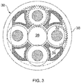
- the epicyclic gearbox 30 is shown by way of example in greater detail in Figure 3 .
- Each of the sun gear 28, planet gears 32 and ring gear 38 comprise teeth about their periphery to intermesh with the other gears. However, for clarity only exemplary portions of the teeth are illustrated in Figure 3 .
- Practical applications of a planetary epicyclic gearbox 30 generally comprise at least three planet gears 32.
- the epicyclic gearbox 30 illustrated by way of example in Figures 2 and 3 is of the planetary type, in that the planet carrier 34 is coupled to an output shaft via linkages 36, with the ring gear 38 fixed.
- the epicyclic gearbox 30 may be a star arrangement, in which the planet carrier 34 is held fixed, with the ring (or annulus) gear 38 allowed to rotate. In such an arrangement the fan 23 is driven by the ring gear 38.
- the gearbox 30 may be a differential gearbox in which the ring gear 38 and the planet carrier 34 are both allowed to rotate.
- any suitable arrangement may be used for locating the power gearbox 30 in the engine 10 and/or for connecting the power gearbox 30 to the engine 10.
- the connections (such as the linkages 36, 40 in the Figure 2 example) between the power gearbox 30 and other parts of the engine 10 (such as the input shaft 26, the output shaft and the fixed structure 24) may have any desired degree of stiffness or flexibility.
- any suitable arrangement of the bearings between rotating and stationary parts of the engine may be used, and the disclosure is not limited to the exemplary arrangement of Figure 2 .
- the power gearbox 30 has a star arrangement (described above)
- the skilled person would readily understand that the arrangement of output and support linkages and bearing locations would typically be different to that shown by way of example in Figure 2 .
- the present disclosure extends to a gas turbine engine having any arrangement of power gearbox styles (for example star or planetary), support structures, input and output shaft arrangement, and bearing locations.
- power gearbox styles for example star or planetary
- support structures for example star or planetary
- input and output shaft arrangement for example star or planetary
- bearing locations for example star or planetary
- the power gearbox may drive additional and/or alternative components (e.g. the intermediate pressure compressor and/or a booster compressor).
- additional and/or alternative components e.g. the intermediate pressure compressor and/or a booster compressor.
- gas turbine engines to which the present disclosure may be applied may have alternative configurations.
- such engines may have an alternative number of compressors and/or turbines and/or an alternative number of interconnecting shafts.
- the gas turbine engine shown in Figure 1 has a split flow nozzle 18, 20 meaning that the flow through the bypass duct 22 has its own nozzle 18 that is separate to and radially outside the core engine nozzle 20.
- this is not limiting, and any aspect of the present disclosure may also apply to engines in which the flow through the bypass duct 22 and the flow through the core 11 are mixed, or combined, before (or upstream of) a single nozzle, which may be referred to as a mixed flow nozzle.
- One or both nozzles may have a fixed or variable area.
- the described example relates to a turbofan engine, the disclosure may apply, for example, to any type of gas turbine engine, such as an open rotor (in which the fan stage is not surrounded by a nacelle) or turboprop engine, for example.
- the gas turbine engine 10 may not comprise a gearbox 30.
- the geometry of the gas turbine engine 10, and components thereof, is defined by a conventional axis system, comprising an axial direction (which is aligned with the rotational axis 9), a radial direction (in the bottom-to-top direction in Figure 1 ), and a circumferential direction (perpendicular to the page in the Figure 1 view).
- the axial, radial and circumferential directions are mutually perpendicular.
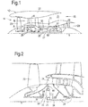
- Figure 4 shows schematically another sectional side view of the gas turbine engine 10.
- a first engine zone is bounded on a radially inner side by a core casing 44 of the engine core 11, on a radially outer side by a core cowl 46 which forms an aerodynamic inner wall of the bypass duct 22, and on a forward side by a fire wall 48.
- an accessory gearbox 40 driven by a take-off (such as a radial drive shaft) from the core shaft 26 is mounted adjacent to and vertically beneath the core casing, along with other accessories 42 driven by the gearbox 40.
- the other accessories 42 may include any one or more of a power generator, fuel pump, oil pumps, a hydraulic pump, and an engine starter motor.
- the engine 10 has an oil system which circulates oil to engine components such as bearings, gears, seals and splines.
- the oil system includes an oil tank 50 which provides a reservoir of oil (indicated in grey in Figure 4 ) to supply the oil system, and a destination for scavenged oil.
- the oil tank 50 is located in a second engine zone between the core casing 44 and the core cowl 46, and forward of the fire wall 48. At this location it wraps around the engine core 11 from bottom to top dead centre.
- the oil tank 50 is within the axial extent of the fan cowl 21, and is thus relatively inaccessible for replenishment by a maintenance engineer. Accordingly, the filling arrangement for the oil tank 50 proceeds via the accessory gearbox 40.
- the oil system includes a fill line 52 which extends from the engine accessory gearbox 40 to an inlet port accessible from through a hatch 54 in the core cowl 46.
- the inlet port and hatch 54 are rearward of the bypass air exit from the fan cowl 21, and are thus unobstructed by the fan cowl.
- Oil collected in the engine accessory gearbox 40 by this arrangement is then directed to the oil tank 50 through a further line, such as a scavenge line 56 from the engine accessory gearbox.
- Sensors (not shown) in the accessory gearbox 40 and the oil tank 50 provide indications of the respective oil levels in these components, and thus the total amount of oil in the system.
- the accessory gearbox 40 contains only a small amount of oil.
- the oil supplied through the inlet port and fill line 52 collects by gravity in the spare space provided by the accessory gearbox 40.
- this oil is drawn through the scavenge line 56 into the oil tank 50 by the operation of the oil pumps.
- Another option is to use a pressure filling system, so that the supplied oil is sent to the oil tank 50 at the time of filling.
- This can allow a larger quantity of oil to be supplied to the oil tank 50 than would otherwise be the case, i.e. to a level above the vertical height of the inlet port.
- a conventional oil pump can be used by the maintenance engineer to pump oil into through the inlet port.
- the inlet port can have a self-sealing closing arrangement to prevent oil back flow.
Landscapes
- Engineering & Computer Science (AREA)
- Chemical & Material Sciences (AREA)
- Combustion & Propulsion (AREA)
- Mechanical Engineering (AREA)
- General Engineering & Computer Science (AREA)
- Structures Of Non-Positive Displacement Pumps (AREA)
Description
- The present disclosure relates to a gas turbine engine and an oil system thereof.
- Modern gas turbine engines generally comprise one or more shafts, each connecting a compressor and a turbine of a respective stage. The shafts are journaled by a series of bearing assemblies. These are cooled and lubricated by means of an oil system which provides a circulating flow of lubricating oil around the bearing assemblies and other components of the engine. The oil system also includes an oil scavenging system for recovering used oil from the various locations in the engine and discharging the recovered used oil into an oil tank, from where it can be pumped back around the system.
- Conventionally, the oil tank of a turbofan gas turbine engine is located at the front of the engine on the fan case. Filling of the oil system is accomplished via the oil tank. For example, the oil tank can have a filling port at an upper side thereof which is accessible through the fan cowl (i.e. nacelle) of the engine. A maintenance engineer in an elevated positon (e.g. on a ladder) can fill the system simply by pouring oil into the tank via the port. A sight glass on the side of the tank can provide the maintenance engineer with an indication of how much oil is in the system.
- A problem arises, however, when the tank is positioned in a more remote location of the engine, such that it cannot be so readily accessed for filling. For example, the tank may be mounted to the core engine rather than the fan case. Further disadvantages of the conventional approach to oil tank filling are that it is possible for an oil cap of the filling port to be left off after filling and that oil is easy to spill during filling which can leave residue inside the fan cowl.
- German patent application
DE 10 2011 112254 A1 discloses a jet engine for aircraft that has accessory gearbox that is coupled to auxiliary units for maintaining temperature of lubrication and cooling agent in tank device integrated in intermediate housing. The jet engine has an inlet region, a secondary flow channel and an engine core. An intermediate housing is partially arranged between the secondary flow channel and engine core. A tank device made of aluminum sheet or composite material is integrated in the intermediate housing for storing the lubricating or cooling agent. The accessory gearbox is coupled to auxiliary units for maintaining the temperature of lubrication and cooling agent in tank device. - The present disclosure provides a gas turbine engine as set out in the appended claims. The present disclosure provides a gas turbine engine for an aircraft comprising:
- an engine core comprising a turbine, a compressor, and a core shaft connecting the turbine to the compressor;
- a core casing surrounding the engine core;
- a core cowl providing an aerodynamic fairing which surrounds the engine core and the core casing;
- an engine accessory gearbox driven by a take-off from the core shaft, and mounted between the core casing and the core cowl; and
- an oil system having one or more oil pumps powered by the engine accessory gearbox for circulating lubricating oil around components of the engine including the engine accessory gearbox, and having an oil tank for receiving and storing oil scavenged from the engine components before recirculation thereto;
- wherein the engine accessory gearbox and the oil tank are mounted between the core casing and the core cowl, with the oil tank being located forward of the engine accessory gearbox; and
- characterised in that the gas turbine engine further comprises an oil fill line which extends from the engine accessory gearbox to an inlet port accessible from the core cowl, the oil tank being fillable from the inlet port via the fill line and the engine accessory gearbox. Advantageously, by filling the oil tank via the fill line and the engine accessory gearbox, the inlet port can be positioned at a convenient and safe location on the engine, even when the oil tank itself is positioned in a relatively inaccessible location.
- Optional features of the present disclosure will now be set out.
- The engine accessory gearbox may be mounted vertically beneath the core casing.
- The oil tank may extend circumferentially around the core casing from bottom dead centre to top dead centre.
- The inlet port may be accessible from the core cowl at a location rearward of the engine accessory gearbox.
- The gas turbine engine may further comprise: a fan located upstream of the engine core, the fan comprising a plurality of fan blades; an annular fan duct extending rearwardly from the fan for a flow of air bypassing the engine core; and a fan cowl surrounding the annular fan duct and defining an exit for the bypass air flow form the fan duct. The inlet port can then be rearward of the bypass air exit from the fan cowl, and hence unobstructed by fan cowl.
- In the present application, "front" and ""rear" are with respect to the gas turbine engine, i.e. the fan being in the front and the exit for the bypass air flow being in the rear. Moreover, "upstream" and "downstream" are with respect to the axial flow of air through the gas turbine engine.
- The gas turbine engine may further comprise respective oil level sensors in the engine accessory gearbox and the oil tank for determining the amount of oil in the oil system. In this way, even if a sight glass is not available on the oil tank, it is possible to determine the amount of oil in the oil system, e.g. by way of display based on the sensor readings and provided to a maintenance engineer.
- Conveniently, the gas turbine may be configured such that oil from the fill line collects in the engine accessory gearbox and is pumped to the oil tank from the engine accessory gearbox on engine startup. For example, the oil collected in the engine accessory gearbox may be pumped to the oil tank via a scavenge line connecting the engine accessory gearbox and the oil tank on engine startup.
- Additionally or alternatively, the gas turbine may be configured such that the oil tank is fillable by injecting pressurised oil at the inlet port. This allows the oil tank to be filled to a level above the vertical height of the inlet port.
- The turbine may be a first turbine, the compressor may be a first compressor, and the core shaft may be a first core shaft, and the engine core may further comprise a second turbine, a second compressor, and a second core shaft connecting the second turbine to the second compressor. In this case, the second core shaft may be arranged to rotate at a different rotational speed than the first core shaft.
- Arrangements of the present disclosure may be particularly, although not exclusively, beneficial for fans that are driven via a power gearbox. Accordingly, the gas turbine engine may comprise a power gearbox that receives an input from the core shaft and outputs drive to the fan so as to drive the fan at a lower rotational speed than the core shaft. The input to the power gearbox may be directly from the core shaft, or indirectly from the core shaft, for example via a spur shaft and/or gear. The core shaft may rigidly connect the turbine and the compressor, such that the turbine and compressor rotate at the same speed (with the fan rotating at a lower speed).
- Embodiments will now be described by way of example only, with reference to the Figures, in which:
-
Figure 1 is a sectional side view of a gas turbine engine; -
Figure 2 is a close up sectional side view of an upstream portion of a gas turbine engine; -
Figure 3 is a partially cut-away view of a power gearbox for a gas turbine engine; and -
Figure 4 shows schematically another sectional side view of the gas turbine engine. - Aspects and embodiments of the present disclosure will now be discussed with reference to the accompanying figures. Further aspects and embodiments will be apparent to those skilled in the art.
-
Figure 1 illustrates agas turbine engine 10 having a principal rotational axis 9. Theengine 10 comprises anair intake 12 and apropulsive fan 23 that generates two airflows: a core airflow A and a bypass airflow B. Thegas turbine engine 10 comprises acore 11 that receives the core airflow A. Theengine core 11 comprises, in axial flow series, alow pressure compressor 14, a high-pressure compressor 15,combustion equipment 16, a high-pressure turbine 17, alow pressure turbine 19 and acore exhaust nozzle 20. A nacelle (i.e. fan cowl) 21 surrounds thegas turbine engine 10 and defines abypass duct 22 and abypass exhaust nozzle 18. The bypass airflow B flows through thebypass duct 22. Thefan 23 is attached to and driven by thelow pressure turbine 19 via ashaft 26 and anepicyclic power gearbox 30. - In use, the core airflow A is accelerated and compressed by the
low pressure compressor 14 and directed into thehigh pressure compressor 15 where further compression takes place. The compressed air exhausted from thehigh pressure compressor 15 is directed into thecombustion equipment 16 where it is mixed with fuel and the mixture is combusted. The resultant hot combustion products then expand through, and thereby drive, the high pressure andlow pressure turbines nozzle 20 to provide some propulsive thrust. Thehigh pressure turbine 17 drives thehigh pressure compressor 15 by a suitable interconnectingshaft 27. Thefan 23 generally provides the majority of the propulsive thrust. Theepicyclic gearbox 30 is a reduction gearbox. - An exemplary arrangement for a geared fan
gas turbine engine 10 is shown inFigure 2 . The low pressure turbine 19 (seeFigure 1 ) drives theshaft 26, which is coupled to a sun wheel, or sun gear, 28 of theepicyclic gear arrangement 30. Radially outwardly of thesun gear 28 and intermeshing therewith is a plurality of planet gears 32 that are coupled together by aplanet carrier 34. Theplanet carrier 34 constrains the planet gears 32 to precess around thesun gear 28 in synchronicity whilst enabling eachplanet gear 32 to rotate about its own axis. Theplanet carrier 34 is coupled vialinkages 36 to thefan 23 in order to drive its rotation about the engine axis 9. Radially outwardly of the planet gears 32 and intermeshing therewith is an annulus orring gear 38 that is coupled, vialinkages 40, to a stationary supportingstructure 24. - Note that the terms "low pressure turbine" and "low pressure compressor" as used herein may be taken to mean the lowest pressure turbine stages and lowest pressure compressor stages (i.e. not including the fan 23) respectively and/or the turbine and compressor stages that are connected together by the interconnecting
shaft 26 with the lowest rotational speed in the engine (i.e. not including the power gearbox output shaft that drives the fan 23). In some literature, the "low pressure turbine" and "low pressure compressor" referred to herein may alternatively be known as the "intermediate pressure turbine" and "intermediate pressure compressor". Where such alternative nomenclature is used, thefan 23 may be referred to as a first, or lowest pressure, compression stage. - The
epicyclic gearbox 30 is shown by way of example in greater detail inFigure 3 . Each of thesun gear 28, planet gears 32 andring gear 38 comprise teeth about their periphery to intermesh with the other gears. However, for clarity only exemplary portions of the teeth are illustrated inFigure 3 . There are fourplanet gears 32 illustrated, although it will be apparent to the skilled reader that more or fewer planet gears 32 may be provided within the scope of the claimed invention. Practical applications of a planetaryepicyclic gearbox 30 generally comprise at least three planet gears 32. - The
epicyclic gearbox 30 illustrated by way of example inFigures 2 and3 is of the planetary type, in that theplanet carrier 34 is coupled to an output shaft vialinkages 36, with thering gear 38 fixed. However, any other suitable type ofepicyclic gearbox 30 may be used. By way of further example, theepicyclic gearbox 30 may be a star arrangement, in which theplanet carrier 34 is held fixed, with the ring (or annulus)gear 38 allowed to rotate. In such an arrangement thefan 23 is driven by thering gear 38. By way of further alternative example, thegearbox 30 may be a differential gearbox in which thering gear 38 and theplanet carrier 34 are both allowed to rotate. - It will be appreciated that the arrangement shown in
Figures 2 and3 is by way of example only, and various alternatives are within the scope of the present disclosure. Purely by way of example, any suitable arrangement may be used for locating thepower gearbox 30 in theengine 10 and/or for connecting thepower gearbox 30 to theengine 10. By way of further example, the connections (such as thelinkages Figure 2 example) between thepower gearbox 30 and other parts of the engine 10 (such as theinput shaft 26, the output shaft and the fixed structure 24) may have any desired degree of stiffness or flexibility. By way of further example, any suitable arrangement of the bearings between rotating and stationary parts of the engine (for example between the input and output shafts from the power gearbox and the fixed structures, such as the power gearbox casing) may be used, and the disclosure is not limited to the exemplary arrangement ofFigure 2 . For example, where thepower gearbox 30 has a star arrangement (described above), the skilled person would readily understand that the arrangement of output and support linkages and bearing locations would typically be different to that shown by way of example inFigure 2 . - Accordingly, the present disclosure extends to a gas turbine engine having any arrangement of power gearbox styles (for example star or planetary), support structures, input and output shaft arrangement, and bearing locations.
- Optionally, the power gearbox may drive additional and/or alternative components (e.g. the intermediate pressure compressor and/or a booster compressor).
- Other gas turbine engines to which the present disclosure may be applied may have alternative configurations. For example, such engines may have an alternative number of compressors and/or turbines and/or an alternative number of interconnecting shafts. By way of further example, the gas turbine engine shown in
Figure 1 has asplit flow nozzle bypass duct 22 has itsown nozzle 18 that is separate to and radially outside thecore engine nozzle 20. However, this is not limiting, and any aspect of the present disclosure may also apply to engines in which the flow through thebypass duct 22 and the flow through the core 11 are mixed, or combined, before (or upstream of) a single nozzle, which may be referred to as a mixed flow nozzle. One or both nozzles (whether mixed or split flow) may have a fixed or variable area. Whilst the described example relates to a turbofan engine, the disclosure may apply, for example, to any type of gas turbine engine, such as an open rotor (in which the fan stage is not surrounded by a nacelle) or turboprop engine, for example. In some arrangements, thegas turbine engine 10 may not comprise agearbox 30. - The geometry of the
gas turbine engine 10, and components thereof, is defined by a conventional axis system, comprising an axial direction (which is aligned with the rotational axis 9), a radial direction (in the bottom-to-top direction inFigure 1 ), and a circumferential direction (perpendicular to the page in theFigure 1 view). The axial, radial and circumferential directions are mutually perpendicular. -
Figure 4 shows schematically another sectional side view of thegas turbine engine 10. A first engine zone is bounded on a radially inner side by acore casing 44 of theengine core 11, on a radially outer side by acore cowl 46 which forms an aerodynamic inner wall of thebypass duct 22, and on a forward side by afire wall 48. Within the zone, anaccessory gearbox 40 driven by a take-off (such as a radial drive shaft) from thecore shaft 26 is mounted adjacent to and vertically beneath the core casing, along withother accessories 42 driven by thegearbox 40. Theother accessories 42 may include any one or more of a power generator, fuel pump, oil pumps, a hydraulic pump, and an engine starter motor. - The
engine 10 has an oil system which circulates oil to engine components such as bearings, gears, seals and splines. The oil system includes anoil tank 50 which provides a reservoir of oil (indicated in grey inFigure 4 ) to supply the oil system, and a destination for scavenged oil. Theoil tank 50 is located in a second engine zone between thecore casing 44 and thecore cowl 46, and forward of thefire wall 48. At this location it wraps around theengine core 11 from bottom to top dead centre. - The
oil tank 50 is within the axial extent of thefan cowl 21, and is thus relatively inaccessible for replenishment by a maintenance engineer. Accordingly, the filling arrangement for theoil tank 50 proceeds via theaccessory gearbox 40. In particular, the oil system includes afill line 52 which extends from theengine accessory gearbox 40 to an inlet port accessible from through ahatch 54 in thecore cowl 46. The inlet port and hatch 54 are rearward of the bypass air exit from thefan cowl 21, and are thus unobstructed by the fan cowl. Oil collected in theengine accessory gearbox 40 by this arrangement is then directed to theoil tank 50 through a further line, such as ascavenge line 56 from the engine accessory gearbox. Sensors (not shown) in theaccessory gearbox 40 and theoil tank 50 provide indications of the respective oil levels in these components, and thus the total amount of oil in the system. - The procedure for replenishing the system with oil can then be as follows:
- 1. The maintenance engineer approaches the engine with a standard can of oil.
- 2. The engineer opens the
hatch 54 in thecore cowl 46. - 3. The engineer releases a filling cap closing the inlet port and pours in oil from the can.
- 4. Aircraft power is used to power the sensors in the
accessory gearbox 40 and theoil tank 50 to give an overall level of the oil in the system. - 5. A display can be provided to the engineer showing the current level so that the engineer can stop pouring when the system is at the required level.
- At engine shutdown the
accessory gearbox 40 contains only a small amount of oil. Thus the oil supplied through the inlet port and fillline 52 collects by gravity in the spare space provided by theaccessory gearbox 40. On engine start up, this oil is drawn through thescavenge line 56 into theoil tank 50 by the operation of the oil pumps. - Another option, however, is to use a pressure filling system, so that the supplied oil is sent to the
oil tank 50 at the time of filling. This can allow a larger quantity of oil to be supplied to theoil tank 50 than would otherwise be the case, i.e. to a level above the vertical height of the inlet port. For example, a conventional oil pump can be used by the maintenance engineer to pump oil into through the inlet port. In this case, the inlet port can have a self-sealing closing arrangement to prevent oil back flow. - It will be understood that the invention is not limited to the embodiments above-described and various modifications and improvements can be made without departing from the concepts described herein within the scope of the following claims.
Claims (11)
- A gas turbine engine (10) for an aircraft comprising:an engine core (11) comprising a turbine (19), a compressor (14), and a core shaft (26) connecting the turbine to the compressor;a core casing (44) surrounding the engine core;a core cowl (46) providing an aerodynamic fairing which surrounds the engine core (11) and the core casing (44);an engine accessory gearbox (40) driven by a take-off from the core shaft, and mounted between the core casing (44) and the core cowl (46); andan oil system having one or more oil pumps powered by the engine accessory gearbox (40) for circulating lubricating oil around components of the engine including the engine accessory gearbox (40), and having an oil tank (50) for receiving and storing oil scavenged from the engine components before recirculation thereto;wherein the engine accessory gearbox (40) and the oil tank (50) are mounted between the core casing (44) and the core cowl (46), with the oil tank being located forward of the engine accessory gearbox (40);characterised in that the gas turbine engine (10) further comprises an oil fill line (52) which extends from the engine accessory gearbox (40) to an inlet port accessible from the core cowl, the oil tank (50) being fillable from the inlet port via the fill line and the engine accessory gearbox (40).
- A gas turbine engine (10) according to claim 1, wherein the engine accessory gearbox (40) is mounted vertically beneath the core casing (44).
- A gas turbine engine (10) according to claim 1 or 2, wherein the oil tank (50) extends circumferentially around the core casing (11) from bottom dead centre to top dead centre.
- A gas turbine engine (10) according to any preceding claim, wherein the inlet port is accessible from the core cowl at a location rearward of the engine accessory gearbox (40).
- A gas turbine engine (10) according to any preceding claim comprising:a fan (23) located upstream of the engine core, the fan comprising a plurality of fan blades;an annular fan duct extending rearwardly from the fan for a flow of air bypassing the engine core (11); anda fan cowl (21) surrounding the annular fan duct and defining an exit for the bypass air flow form the fan duct;wherein the inlet port is rearward of the bypass air exit from the fan cowl.
- A gas turbine engine (10) according to any preceding claim further comprising:
a power gearbox (30) that receives an input from the core shaft (26) and outputs drive to the fan (23) so as to drive the fan at a lower rotational speed than the core shaft. - A gas turbine engine (10) according to any preceding claim further comprising respective oil level sensors in the engine accessory gearbox (40) and the oil tank (50) for determining the amount of oil in the oil system.
- A gas turbine engine (10) according to any preceding claim which is configured such that oil from the fill line (52) collects in the engine accessory gearbox (40) and is pumped to the oil tank (50) from the engine accessory gearbox on engine startup.
- A gas turbine engine (10) according to claim 8, wherein the oil collected in the engine accessory gearbox (40) is pumped to the oil tank (50) via a scavenge line (56) connecting the engine accessory gearbox and the oil tank on engine startup.
- A gas turbine engine (10) according to any preceding claim which is configured such that the oil tank (50) is fillable by injecting pressurised oil at the inlet port.
- A gas turbine engine according to any preceding claim, wherein:the turbine is a first turbine (19), the compressor is a first compressor (14), and the core shaft is a first core shaft (26);the engine core further comprises a second turbine (17), a second compressor (15), and a second core shaft (27) connecting the second turbine to the second compressor; andthe second core shaft is arranged to rotate at a different rotational speed than the first core shaft.
Applications Claiming Priority (1)
| Application Number | Priority Date | Filing Date | Title |
|---|---|---|---|
| GBGB1804579.9A GB201804579D0 (en) | 2018-03-22 | 2018-03-22 | Gas turbine engine and oil system thereof |
Publications (2)
| Publication Number | Publication Date |
|---|---|
| EP3543506A1 EP3543506A1 (en) | 2019-09-25 |
| EP3543506B1 true EP3543506B1 (en) | 2021-02-03 |
Family
ID=62068207
Family Applications (1)
| Application Number | Title | Priority Date | Filing Date |
|---|---|---|---|
| EP19162252.1A Active EP3543506B1 (en) | 2018-03-22 | 2019-03-12 | Gas turbine engine and oil system thereof |
Country Status (4)
| Country | Link |
|---|---|
| US (1) | US11415023B2 (en) |
| EP (1) | EP3543506B1 (en) |
| CN (1) | CN110295999B (en) |
| GB (1) | GB201804579D0 (en) |
Families Citing this family (9)
| Publication number | Priority date | Publication date | Assignee | Title |
|---|---|---|---|---|
| FR3079873B1 (en) * | 2018-04-04 | 2020-05-08 | Safran Aircraft Engines | ENGINE ASSEMBLY FOR AN AIRCRAFT HAVING A FEEDING PATH FOR A TANK OF A TURBOMACHINE INTER-VEIN COMPARTMENT |
| GB201807200D0 (en) * | 2018-05-02 | 2018-06-13 | Rolls Royce Plc | Oil tank filling system |
| FR3082560B1 (en) * | 2018-06-14 | 2020-08-28 | Safran Aircraft Engines | ON-BOARD SYSTEM AND METHOD FOR DRAINING AN AIRCRAFT ENGINE |
| US11230947B2 (en) * | 2019-06-20 | 2022-01-25 | Pratt & Whitney Canada Corp. | Gas turbine engine having oil level measurement system |
| DE102019126093A1 (en) * | 2019-09-27 | 2021-04-01 | Rolls-Royce Deutschland Ltd & Co Kg | Gas turbine engine of an aircraft with a gearbox |
| JP7445452B2 (en) * | 2020-02-14 | 2024-03-07 | 川崎重工業株式会社 | gas turbine engine |
| CN111895259B (en) * | 2020-07-10 | 2021-11-12 | 中国航发湖南动力机械研究所 | Integrated oil storage tank |
| US11572838B2 (en) * | 2020-09-29 | 2023-02-07 | General Electric Company | Accessory gearbox for a turbine engine |
| US20260022668A1 (en) * | 2024-07-16 | 2026-01-22 | Rtx Corporation | Gearbox arrangement for dual spool engine accessories |
Family Cites Families (8)
| Publication number | Priority date | Publication date | Assignee | Title |
|---|---|---|---|---|
| US8627667B2 (en) | 2008-12-29 | 2014-01-14 | Roll-Royce Corporation | Gas turbine engine duct having a coupled fluid volume |
| DE102011112254A1 (en) | 2011-09-02 | 2013-03-07 | Rolls-Royce Deutschland Ltd & Co Kg | Jet engine for aircraft, has accessory gearbox that is coupled to auxiliary units for maintaining temperature of lubrication and cooling agent in tank device integrated in intermediate housing |
| US9194294B2 (en) | 2012-05-07 | 2015-11-24 | United Technologies Corporation | Gas turbine engine oil tank |
| US9945252B2 (en) | 2012-07-05 | 2018-04-17 | United Technologies Corporation | Gas turbine engine oil tank with integrated packaging configuration |
| US9371743B2 (en) | 2013-02-21 | 2016-06-21 | United Technologies Corporation | Cap drain plug |
| FR3008449B1 (en) * | 2013-07-12 | 2015-07-24 | Snecma | OIL COOLING DEVICE FOR A TURBOMACHINE |
| FR3010701B1 (en) | 2013-09-13 | 2015-10-09 | Snecma | ARRANGEMENT OF A TANK BETWEEN A NACELLE HOOD AND A TURBOMACHINE |
| US10072582B2 (en) | 2016-04-28 | 2018-09-11 | General Electric Company | Integral offset oil tank for inline accessory gearbox |
-
2018
- 2018-03-22 GB GBGB1804579.9A patent/GB201804579D0/en not_active Ceased
-
2019
- 2019-03-04 US US16/291,019 patent/US11415023B2/en active Active
- 2019-03-12 EP EP19162252.1A patent/EP3543506B1/en active Active
- 2019-03-22 CN CN201910221745.3A patent/CN110295999B/en active Active
Non-Patent Citations (1)
| Title |
|---|
| None * |
Also Published As
| Publication number | Publication date |
|---|---|
| US11415023B2 (en) | 2022-08-16 |
| US20200025033A1 (en) | 2020-01-23 |
| CN110295999A (en) | 2019-10-01 |
| CN110295999B (en) | 2023-06-13 |
| GB201804579D0 (en) | 2018-05-09 |
| EP3543506A1 (en) | 2019-09-25 |
Similar Documents
| Publication | Publication Date | Title |
|---|---|---|
| EP3543506B1 (en) | Gas turbine engine and oil system thereof | |
| US11203974B2 (en) | Auxiliary oil system for geared gas turbine engine | |
| US20250164003A1 (en) | Electric motor driven auxiliary oil system for geared gas turbine engine | |
| EP3184780B1 (en) | Electric windmill pump for improved gearbox durability of a geared fan engine | |
| US10570824B2 (en) | Near zero velocity lubrication system for a turbine engine | |
| US5845483A (en) | Windmill engine starting system with fluid driven motor and pump | |
| EP3564498B1 (en) | Turbofan engine with oil tank filling system | |
| JP6672477B2 (en) | Integrated offset oil tank for in-line attached gearbox | |
| WO2015147949A2 (en) | Auxiliary oil system for geared gas turbine engine | |
| US11913388B2 (en) | Cabin blower system | |
| US11156124B2 (en) | Oil tank filling system | |
| EP3835561A1 (en) | Oil system | |
| US11174755B2 (en) | Oil tank filling system | |
| CN110435903B (en) | Oil tank filling system | |
| EP4722501A1 (en) | Lubrication circuit with bearing compartment electric pump in scavenger line | |
| EP3553294A2 (en) | Accessory gearbox | |
| WO2020078724A1 (en) | Oil system of a gas turbine engine and gas turbine engine |
Legal Events
| Date | Code | Title | Description |
|---|---|---|---|
| PUAI | Public reference made under article 153(3) epc to a published international application that has entered the european phase |
Free format text: ORIGINAL CODE: 0009012 |
|
| STAA | Information on the status of an ep patent application or granted ep patent |
Free format text: STATUS: THE APPLICATION HAS BEEN PUBLISHED |
|
| AK | Designated contracting states |
Kind code of ref document: A1 Designated state(s): AL AT BE BG CH CY CZ DE DK EE ES FI FR GB GR HR HU IE IS IT LI LT LU LV MC MK MT NL NO PL PT RO RS SE SI SK SM TR |
|
| AX | Request for extension of the european patent |
Extension state: BA ME |
|
| STAA | Information on the status of an ep patent application or granted ep patent |
Free format text: STATUS: REQUEST FOR EXAMINATION WAS MADE |
|
| 17P | Request for examination filed |
Effective date: 20191115 |
|
| RBV | Designated contracting states (corrected) |
Designated state(s): AL AT BE BG CH CY CZ DE DK EE ES FI FR GB GR HR HU IE IS IT LI LT LU LV MC MK MT NL NO PL PT RO RS SE SI SK SM TR |
|
| RAP1 | Party data changed (applicant data changed or rights of an application transferred) |
Owner name: ROLLS-ROYCE PLC |
|
| GRAP | Despatch of communication of intention to grant a patent |
Free format text: ORIGINAL CODE: EPIDOSNIGR1 |
|
| STAA | Information on the status of an ep patent application or granted ep patent |
Free format text: STATUS: GRANT OF PATENT IS INTENDED |
|
| INTG | Intention to grant announced |
Effective date: 20201012 |
|
| GRAS | Grant fee paid |
Free format text: ORIGINAL CODE: EPIDOSNIGR3 |
|
| GRAA | (expected) grant |
Free format text: ORIGINAL CODE: 0009210 |
|
| STAA | Information on the status of an ep patent application or granted ep patent |
Free format text: STATUS: THE PATENT HAS BEEN GRANTED |
|
| AK | Designated contracting states |
Kind code of ref document: B1 Designated state(s): AL AT BE BG CH CY CZ DE DK EE ES FI FR GB GR HR HU IE IS IT LI LT LU LV MC MK MT NL NO PL PT RO RS SE SI SK SM TR |
|
| REG | Reference to a national code |
Ref country code: GB Ref legal event code: FG4D |
|
| REG | Reference to a national code |
Ref country code: CH Ref legal event code: EP Ref country code: AT Ref legal event code: REF Ref document number: 1359748 Country of ref document: AT Kind code of ref document: T Effective date: 20210215 |
|
| REG | Reference to a national code |
Ref country code: DE Ref legal event code: R096 Ref document number: 602019002415 Country of ref document: DE |
|
| REG | Reference to a national code |
Ref country code: IE Ref legal event code: FG4D |
|
| REG | Reference to a national code |
Ref country code: NL Ref legal event code: MP Effective date: 20210203 |
|
| REG | Reference to a national code |
Ref country code: LT Ref legal event code: MG9D |
|
| REG | Reference to a national code |
Ref country code: AT Ref legal event code: MK05 Ref document number: 1359748 Country of ref document: AT Kind code of ref document: T Effective date: 20210203 |
|
| PG25 | Lapsed in a contracting state [announced via postgrant information from national office to epo] |
Ref country code: LT Free format text: LAPSE BECAUSE OF FAILURE TO SUBMIT A TRANSLATION OF THE DESCRIPTION OR TO PAY THE FEE WITHIN THE PRESCRIBED TIME-LIMIT Effective date: 20210203 Ref country code: NO Free format text: LAPSE BECAUSE OF FAILURE TO SUBMIT A TRANSLATION OF THE DESCRIPTION OR TO PAY THE FEE WITHIN THE PRESCRIBED TIME-LIMIT Effective date: 20210503 Ref country code: PT Free format text: LAPSE BECAUSE OF FAILURE TO SUBMIT A TRANSLATION OF THE DESCRIPTION OR TO PAY THE FEE WITHIN THE PRESCRIBED TIME-LIMIT Effective date: 20210604 Ref country code: GR Free format text: LAPSE BECAUSE OF FAILURE TO SUBMIT A TRANSLATION OF THE DESCRIPTION OR TO PAY THE FEE WITHIN THE PRESCRIBED TIME-LIMIT Effective date: 20210504 Ref country code: FI Free format text: LAPSE BECAUSE OF FAILURE TO SUBMIT A TRANSLATION OF THE DESCRIPTION OR TO PAY THE FEE WITHIN THE PRESCRIBED TIME-LIMIT Effective date: 20210203 Ref country code: HR Free format text: LAPSE BECAUSE OF FAILURE TO SUBMIT A TRANSLATION OF THE DESCRIPTION OR TO PAY THE FEE WITHIN THE PRESCRIBED TIME-LIMIT Effective date: 20210203 Ref country code: BG Free format text: LAPSE BECAUSE OF FAILURE TO SUBMIT A TRANSLATION OF THE DESCRIPTION OR TO PAY THE FEE WITHIN THE PRESCRIBED TIME-LIMIT Effective date: 20210503 |
|
| PG25 | Lapsed in a contracting state [announced via postgrant information from national office to epo] |
Ref country code: SE Free format text: LAPSE BECAUSE OF FAILURE TO SUBMIT A TRANSLATION OF THE DESCRIPTION OR TO PAY THE FEE WITHIN THE PRESCRIBED TIME-LIMIT Effective date: 20210203 Ref country code: AT Free format text: LAPSE BECAUSE OF FAILURE TO SUBMIT A TRANSLATION OF THE DESCRIPTION OR TO PAY THE FEE WITHIN THE PRESCRIBED TIME-LIMIT Effective date: 20210203 Ref country code: RS Free format text: LAPSE BECAUSE OF FAILURE TO SUBMIT A TRANSLATION OF THE DESCRIPTION OR TO PAY THE FEE WITHIN THE PRESCRIBED TIME-LIMIT Effective date: 20210203 Ref country code: LV Free format text: LAPSE BECAUSE OF FAILURE TO SUBMIT A TRANSLATION OF THE DESCRIPTION OR TO PAY THE FEE WITHIN THE PRESCRIBED TIME-LIMIT Effective date: 20210203 Ref country code: NL Free format text: LAPSE BECAUSE OF FAILURE TO SUBMIT A TRANSLATION OF THE DESCRIPTION OR TO PAY THE FEE WITHIN THE PRESCRIBED TIME-LIMIT Effective date: 20210203 Ref country code: PL Free format text: LAPSE BECAUSE OF FAILURE TO SUBMIT A TRANSLATION OF THE DESCRIPTION OR TO PAY THE FEE WITHIN THE PRESCRIBED TIME-LIMIT Effective date: 20210203 |
|
| PG25 | Lapsed in a contracting state [announced via postgrant information from national office to epo] |
Ref country code: IS Free format text: LAPSE BECAUSE OF FAILURE TO SUBMIT A TRANSLATION OF THE DESCRIPTION OR TO PAY THE FEE WITHIN THE PRESCRIBED TIME-LIMIT Effective date: 20210603 |
|
| PG25 | Lapsed in a contracting state [announced via postgrant information from national office to epo] |
Ref country code: SM Free format text: LAPSE BECAUSE OF FAILURE TO SUBMIT A TRANSLATION OF THE DESCRIPTION OR TO PAY THE FEE WITHIN THE PRESCRIBED TIME-LIMIT Effective date: 20210203 Ref country code: CZ Free format text: LAPSE BECAUSE OF FAILURE TO SUBMIT A TRANSLATION OF THE DESCRIPTION OR TO PAY THE FEE WITHIN THE PRESCRIBED TIME-LIMIT Effective date: 20210203 Ref country code: EE Free format text: LAPSE BECAUSE OF FAILURE TO SUBMIT A TRANSLATION OF THE DESCRIPTION OR TO PAY THE FEE WITHIN THE PRESCRIBED TIME-LIMIT Effective date: 20210203 |
|
| REG | Reference to a national code |
Ref country code: DE Ref legal event code: R097 Ref document number: 602019002415 Country of ref document: DE |
|
| PG25 | Lapsed in a contracting state [announced via postgrant information from national office to epo] |
Ref country code: MC Free format text: LAPSE BECAUSE OF FAILURE TO SUBMIT A TRANSLATION OF THE DESCRIPTION OR TO PAY THE FEE WITHIN THE PRESCRIBED TIME-LIMIT Effective date: 20210203 Ref country code: RO Free format text: LAPSE BECAUSE OF FAILURE TO SUBMIT A TRANSLATION OF THE DESCRIPTION OR TO PAY THE FEE WITHIN THE PRESCRIBED TIME-LIMIT Effective date: 20210203 Ref country code: SK Free format text: LAPSE BECAUSE OF FAILURE TO SUBMIT A TRANSLATION OF THE DESCRIPTION OR TO PAY THE FEE WITHIN THE PRESCRIBED TIME-LIMIT Effective date: 20210203 Ref country code: DK Free format text: LAPSE BECAUSE OF FAILURE TO SUBMIT A TRANSLATION OF THE DESCRIPTION OR TO PAY THE FEE WITHIN THE PRESCRIBED TIME-LIMIT Effective date: 20210203 |
|
| PLBE | No opposition filed within time limit |
Free format text: ORIGINAL CODE: 0009261 |
|
| STAA | Information on the status of an ep patent application or granted ep patent |
Free format text: STATUS: NO OPPOSITION FILED WITHIN TIME LIMIT |
|
| REG | Reference to a national code |
Ref country code: BE Ref legal event code: MM Effective date: 20210331 |
|
| 26N | No opposition filed |
Effective date: 20211104 |
|
| PG25 | Lapsed in a contracting state [announced via postgrant information from national office to epo] |
Ref country code: ES Free format text: LAPSE BECAUSE OF FAILURE TO SUBMIT A TRANSLATION OF THE DESCRIPTION OR TO PAY THE FEE WITHIN THE PRESCRIBED TIME-LIMIT Effective date: 20210203 Ref country code: AL Free format text: LAPSE BECAUSE OF FAILURE TO SUBMIT A TRANSLATION OF THE DESCRIPTION OR TO PAY THE FEE WITHIN THE PRESCRIBED TIME-LIMIT Effective date: 20210203 Ref country code: IE Free format text: LAPSE BECAUSE OF NON-PAYMENT OF DUE FEES Effective date: 20210312 Ref country code: LU Free format text: LAPSE BECAUSE OF NON-PAYMENT OF DUE FEES Effective date: 20210312 |
|
| PG25 | Lapsed in a contracting state [announced via postgrant information from national office to epo] |
Ref country code: SI Free format text: LAPSE BECAUSE OF FAILURE TO SUBMIT A TRANSLATION OF THE DESCRIPTION OR TO PAY THE FEE WITHIN THE PRESCRIBED TIME-LIMIT Effective date: 20210203 |
|
| PG25 | Lapsed in a contracting state [announced via postgrant information from national office to epo] |
Ref country code: IT Free format text: LAPSE BECAUSE OF FAILURE TO SUBMIT A TRANSLATION OF THE DESCRIPTION OR TO PAY THE FEE WITHIN THE PRESCRIBED TIME-LIMIT Effective date: 20210203 |
|
| PG25 | Lapsed in a contracting state [announced via postgrant information from national office to epo] |
Ref country code: IS Free format text: LAPSE BECAUSE OF FAILURE TO SUBMIT A TRANSLATION OF THE DESCRIPTION OR TO PAY THE FEE WITHIN THE PRESCRIBED TIME-LIMIT Effective date: 20210603 |
|
| PG25 | Lapsed in a contracting state [announced via postgrant information from national office to epo] |
Ref country code: BE Free format text: LAPSE BECAUSE OF NON-PAYMENT OF DUE FEES Effective date: 20210331 |
|
| REG | Reference to a national code |
Ref country code: CH Ref legal event code: PL |
|
| PG25 | Lapsed in a contracting state [announced via postgrant information from national office to epo] |
Ref country code: LI Free format text: LAPSE BECAUSE OF NON-PAYMENT OF DUE FEES Effective date: 20220331 Ref country code: CH Free format text: LAPSE BECAUSE OF NON-PAYMENT OF DUE FEES Effective date: 20220331 |
|
| PG25 | Lapsed in a contracting state [announced via postgrant information from national office to epo] |
Ref country code: CY Free format text: LAPSE BECAUSE OF FAILURE TO SUBMIT A TRANSLATION OF THE DESCRIPTION OR TO PAY THE FEE WITHIN THE PRESCRIBED TIME-LIMIT Effective date: 20210203 |
|
| P01 | Opt-out of the competence of the unified patent court (upc) registered |
Effective date: 20230528 |
|
| PG25 | Lapsed in a contracting state [announced via postgrant information from national office to epo] |
Ref country code: HU Free format text: LAPSE BECAUSE OF FAILURE TO SUBMIT A TRANSLATION OF THE DESCRIPTION OR TO PAY THE FEE WITHIN THE PRESCRIBED TIME-LIMIT; INVALID AB INITIO Effective date: 20190312 |
|
| PG25 | Lapsed in a contracting state [announced via postgrant information from national office to epo] |
Ref country code: MK Free format text: LAPSE BECAUSE OF FAILURE TO SUBMIT A TRANSLATION OF THE DESCRIPTION OR TO PAY THE FEE WITHIN THE PRESCRIBED TIME-LIMIT Effective date: 20210203 |
|
| PG25 | Lapsed in a contracting state [announced via postgrant information from national office to epo] |
Ref country code: MT Free format text: LAPSE BECAUSE OF FAILURE TO SUBMIT A TRANSLATION OF THE DESCRIPTION OR TO PAY THE FEE WITHIN THE PRESCRIBED TIME-LIMIT Effective date: 20210203 |
|
| PG25 | Lapsed in a contracting state [announced via postgrant information from national office to epo] |
Ref country code: TR Free format text: LAPSE BECAUSE OF FAILURE TO SUBMIT A TRANSLATION OF THE DESCRIPTION OR TO PAY THE FEE WITHIN THE PRESCRIBED TIME-LIMIT Effective date: 20210203 |
|
| PGFP | Annual fee paid to national office [announced via postgrant information from national office to epo] |
Ref country code: GB Payment date: 20260323 Year of fee payment: 8 |
|
| PGFP | Annual fee paid to national office [announced via postgrant information from national office to epo] |
Ref country code: DE Payment date: 20260320 Year of fee payment: 8 |
|
| PGFP | Annual fee paid to national office [announced via postgrant information from national office to epo] |
Ref country code: FR Payment date: 20260323 Year of fee payment: 8 |