EP3543464A1 - Dual cavity baffle - Google Patents
Dual cavity baffle Download PDFInfo
- Publication number
- EP3543464A1 EP3543464A1 EP19154303.2A EP19154303A EP3543464A1 EP 3543464 A1 EP3543464 A1 EP 3543464A1 EP 19154303 A EP19154303 A EP 19154303A EP 3543464 A1 EP3543464 A1 EP 3543464A1
- Authority
- EP
- European Patent Office
- Prior art keywords
- baffle
- cavity
- component
- baffle cavity
- chamber
- Prior art date
- Legal status (The legal status is an assumption and is not a legal conclusion. Google has not performed a legal analysis and makes no representation as to the accuracy of the status listed.)
- Granted
Links
Images



Classifications
-
- F—MECHANICAL ENGINEERING; LIGHTING; HEATING; WEAPONS; BLASTING
- F01—MACHINES OR ENGINES IN GENERAL; ENGINE PLANTS IN GENERAL; STEAM ENGINES
- F01D—NON-POSITIVE DISPLACEMENT MACHINES OR ENGINES, e.g. STEAM TURBINES
- F01D5/00—Blades; Blade-carrying members; Heating, heat-insulating, cooling or antivibration means on the blades or the members
- F01D5/12—Blades
- F01D5/14—Form or construction
- F01D5/18—Hollow blades, i.e. blades with cooling or heating channels or cavities; Heating, heat-insulating or cooling means on blades
- F01D5/187—Convection cooling
- F01D5/188—Convection cooling with an insert in the blade cavity to guide the cooling fluid, e.g. forming a separation wall
-
- F—MECHANICAL ENGINEERING; LIGHTING; HEATING; WEAPONS; BLASTING
- F01—MACHINES OR ENGINES IN GENERAL; ENGINE PLANTS IN GENERAL; STEAM ENGINES
- F01D—NON-POSITIVE DISPLACEMENT MACHINES OR ENGINES, e.g. STEAM TURBINES
- F01D25/00—Component parts, details, or accessories, not provided for in, or of interest apart from, other groups
- F01D25/08—Cooling; Heating; Heat-insulation
- F01D25/12—Cooling
-
- F—MECHANICAL ENGINEERING; LIGHTING; HEATING; WEAPONS; BLASTING
- F01—MACHINES OR ENGINES IN GENERAL; ENGINE PLANTS IN GENERAL; STEAM ENGINES
- F01D—NON-POSITIVE DISPLACEMENT MACHINES OR ENGINES, e.g. STEAM TURBINES
- F01D5/00—Blades; Blade-carrying members; Heating, heat-insulating, cooling or antivibration means on the blades or the members
- F01D5/12—Blades
- F01D5/14—Form or construction
- F01D5/18—Hollow blades, i.e. blades with cooling or heating channels or cavities; Heating, heat-insulating or cooling means on blades
- F01D5/187—Convection cooling
- F01D5/188—Convection cooling with an insert in the blade cavity to guide the cooling fluid, e.g. forming a separation wall
- F01D5/189—Convection cooling with an insert in the blade cavity to guide the cooling fluid, e.g. forming a separation wall the insert having a tubular cross-section, e.g. airfoil shape
-
- F—MECHANICAL ENGINEERING; LIGHTING; HEATING; WEAPONS; BLASTING
- F01—MACHINES OR ENGINES IN GENERAL; ENGINE PLANTS IN GENERAL; STEAM ENGINES
- F01D—NON-POSITIVE DISPLACEMENT MACHINES OR ENGINES, e.g. STEAM TURBINES
- F01D9/00—Stators
- F01D9/02—Nozzles; Nozzle boxes; Stator blades; Guide conduits, e.g. individual nozzles
- F01D9/04—Nozzles; Nozzle boxes; Stator blades; Guide conduits, e.g. individual nozzles forming ring or sector
- F01D9/041—Nozzles; Nozzle boxes; Stator blades; Guide conduits, e.g. individual nozzles forming ring or sector using blades
-
- F—MECHANICAL ENGINEERING; LIGHTING; HEATING; WEAPONS; BLASTING
- F02—COMBUSTION ENGINES; HOT-GAS OR COMBUSTION-PRODUCT ENGINE PLANTS
- F02C—GAS-TURBINE PLANTS; AIR INTAKES FOR JET-PROPULSION PLANTS; CONTROLLING FUEL SUPPLY IN AIR-BREATHING JET-PROPULSION PLANTS
- F02C3/00—Gas-turbine plants characterised by the use of combustion products as the working fluid
- F02C3/04—Gas-turbine plants characterised by the use of combustion products as the working fluid having a turbine driving a compressor
- F02C3/06—Gas-turbine plants characterised by the use of combustion products as the working fluid having a turbine driving a compressor the compressor comprising only axial stages
-
- F—MECHANICAL ENGINEERING; LIGHTING; HEATING; WEAPONS; BLASTING
- F05—INDEXING SCHEMES RELATING TO ENGINES OR PUMPS IN VARIOUS SUBCLASSES OF CLASSES F01-F04
- F05D—INDEXING SCHEME FOR ASPECTS RELATING TO NON-POSITIVE-DISPLACEMENT MACHINES OR ENGINES, GAS-TURBINES OR JET-PROPULSION PLANTS
- F05D2220/00—Application
- F05D2220/30—Application in turbines
- F05D2220/32—Application in turbines in gas turbines
-
- F—MECHANICAL ENGINEERING; LIGHTING; HEATING; WEAPONS; BLASTING
- F05—INDEXING SCHEMES RELATING TO ENGINES OR PUMPS IN VARIOUS SUBCLASSES OF CLASSES F01-F04
- F05D—INDEXING SCHEME FOR ASPECTS RELATING TO NON-POSITIVE-DISPLACEMENT MACHINES OR ENGINES, GAS-TURBINES OR JET-PROPULSION PLANTS
- F05D2240/00—Components
- F05D2240/10—Stators
- F05D2240/12—Fluid guiding means, e.g. vanes
- F05D2240/121—Fluid guiding means, e.g. vanes related to the leading edge of a stator vane
-
- F—MECHANICAL ENGINEERING; LIGHTING; HEATING; WEAPONS; BLASTING
- F05—INDEXING SCHEMES RELATING TO ENGINES OR PUMPS IN VARIOUS SUBCLASSES OF CLASSES F01-F04
- F05D—INDEXING SCHEME FOR ASPECTS RELATING TO NON-POSITIVE-DISPLACEMENT MACHINES OR ENGINES, GAS-TURBINES OR JET-PROPULSION PLANTS
- F05D2240/00—Components
- F05D2240/10—Stators
- F05D2240/12—Fluid guiding means, e.g. vanes
- F05D2240/122—Fluid guiding means, e.g. vanes related to the trailing edge of a stator vane
-
- F—MECHANICAL ENGINEERING; LIGHTING; HEATING; WEAPONS; BLASTING
- F05—INDEXING SCHEMES RELATING TO ENGINES OR PUMPS IN VARIOUS SUBCLASSES OF CLASSES F01-F04
- F05D—INDEXING SCHEME FOR ASPECTS RELATING TO NON-POSITIVE-DISPLACEMENT MACHINES OR ENGINES, GAS-TURBINES OR JET-PROPULSION PLANTS
- F05D2260/00—Function
- F05D2260/20—Heat transfer, e.g. cooling
- F05D2260/201—Heat transfer, e.g. cooling by impingement of a fluid
-
- F—MECHANICAL ENGINEERING; LIGHTING; HEATING; WEAPONS; BLASTING
- F05—INDEXING SCHEMES RELATING TO ENGINES OR PUMPS IN VARIOUS SUBCLASSES OF CLASSES F01-F04
- F05D—INDEXING SCHEME FOR ASPECTS RELATING TO NON-POSITIVE-DISPLACEMENT MACHINES OR ENGINES, GAS-TURBINES OR JET-PROPULSION PLANTS
- F05D2260/00—Function
- F05D2260/20—Heat transfer, e.g. cooling
- F05D2260/221—Improvement of heat transfer
-
- Y—GENERAL TAGGING OF NEW TECHNOLOGICAL DEVELOPMENTS; GENERAL TAGGING OF CROSS-SECTIONAL TECHNOLOGIES SPANNING OVER SEVERAL SECTIONS OF THE IPC; TECHNICAL SUBJECTS COVERED BY FORMER USPC CROSS-REFERENCE ART COLLECTIONS [XRACs] AND DIGESTS
- Y02—TECHNOLOGIES OR APPLICATIONS FOR MITIGATION OR ADAPTATION AGAINST CLIMATE CHANGE
- Y02T—CLIMATE CHANGE MITIGATION TECHNOLOGIES RELATED TO TRANSPORTATION
- Y02T50/00—Aeronautics or air transport
- Y02T50/60—Efficient propulsion technologies, e.g. for aircraft
Definitions
- This application relates to cooling a component of a gas turbine engine, and more particularly to a dual cavity baffle for cooling a component.
- Gas turbine engines typically include a fan delivering air for propulsion and for cooling components.
- the fan also delivers air into a compressor where air is compressed and delivered into a combustor.
- the air is mixed with fuel and ignited. Products of this combustion pass downstream over turbine rotors driving them to rotate.
- the turbine rotors in turn, rotate compressor rotors and the fan rotor.
- Stator vanes are positioned adjacent to turbine blades in a gas turbine and are subject to high temperatures.
- a baffle defines a single baffle cavity that is disposed within an interior cavity of the stator vane, and cooling air is directed outwards from within the single baffle cavity to the interior cavity.
- a component for a gas turbine engine includes a body that has an airfoil extending between a radially inner platform and a radially outer platform, and that has an internal cavity within the airfoil.
- a baffle is disposed within the internal cavity.
- the baffle defines first and second baffle cavities that are separated by a baffle dividing wall extending between the radially inner platform and the radially outer platform.
- An impingement plate is spaced apart from one of the radially inner and outer platforms, includes a first opening that provides fluid communication between a first chamber and the first baffle cavity, and includes a plurality of second openings that are smaller than the first opening and provide fluid communication between the first chamber and the second baffle cavity via a second chamber.
- the first baffle cavity extends in a radial direction beyond the one of the inner and outer diameter platforms to the impingement plate at a first end, and a terminal end of the second baffle cavity proximate to the one of the radially inner and outer platforms is spaced apart from the impingement plate.
- the second baffle cavity is open at both of its opposing ends, and the first baffle cavity is closed at a second end that is opposite the first end of the first baffle cavity.
- the first baffle cavity is situated proximate to a leading edge of the airfoil, and the second baffle cavity is situated proximate to a trailing edge of the airfoil.
- the first baffle cavity is situated proximate to a trailing edge of the airfoil, and the second baffle cavity is situated proximate to a leading edge of the airfoil.
- a U-shaped collar extends between the one of the radially inner and outer platforms and the impingement plate and surrounds a portion of the baffle.
- the collar comprises ends that terminate at the baffle dividing wall.
- the baffle dividing wall is free of openings between the first and second cavities.
- the second chamber is fluidly isolated from the first baffle cavity.
- the impingement plate is free of openings within a profile of the second baffle cavity.
- one of the first and second baffle cavities is disposed along a leading edge of the baffle and includes a plurality of sidewall openings that are disposed between the radially inner and radially outer platforms and that open to the internal cavity for directing cooling air from within the one of the first and second cavities to the internal cavity.
- a second of the first and second cavities is free of sidewall openings.
- a second of the first and second cavities comprises a quantity of sidewall openings that is less than a quantity of sidewall openings of the one of the first and second cavities.
- the one of the radially inner and outer platforms is the radially outer platform.
- the one of the radially inner and outer platforms is the radially inner platform.
- the body having an airfoil includes a stator vane.
- a gas turbine engine includes a compressor section, a combustor section in fluid communication with the compressor section, and a turbine section in fluid communication with the combustor section.
- the turbine section has an engine component that extends between a radially inner platform and a radially outer platform and includes an airfoil that has an internal cavity.
- a baffle is disposed within the internal cavity. The baffle defines first and second baffle cavities that are separated by a baffle dividing wall that extends between the radially inner platform and the radially outer platform.
- An impingement plate spaced apart from one of the radially inner and outer platforms includes a first opening that provides fluid communication between a first chamber and the first baffle cavity, and includes a plurality of second openings that are smaller than the first opening and provide fluid communication between the first chamber and the second baffle cavity via a second chamber.
- the first chamber is in fluid communication with a source of cooling air.
- the first baffle cavity extends in a radial direction beyond the one of the inner and outer diameter platforms to the impingement plate at a first end, and a terminal end of the second baffle cavity proximate to the one of the radially inner and outer platforms is spaced apart from the impingement plate.
- one of the first and second baffle cavities is disposed along a leading edge of the baffle and comprises a plurality of sidewall openings that are disposed between the radially inner and outer platforms and that open to the internal cavity for directing cooling air from within the one of the first and second cavities to the internal cavity.
- a U-shaped collar extends between the one of the radially inner and outer platforms and the impingement plate and surrounds a portion of the baffle.
- FIG. 1 schematically illustrates a gas turbine engine 20.
- the gas turbine engine 20 is disclosed herein as a two-spool turbofan that generally incorporates a fan section 22, a compressor section 24, a combustor section 26, and a turbine section 28.
- Alternative engines might include an augmentor section (not shown) among other systems or features.
- the fan section 22 drives air along a bypass flow path B in a bypass duct defined within a nacelle 15, and also drives air along a core flow path C for compression and communication into the combustor section 26 then expansion through the turbine section 28.
- the exemplary engine 20 generally includes a low speed spool 30 and a high speed spool 32 mounted for rotation about an engine central longitudinal axis A relative to an engine static structure 36 via several bearing systems 38. It should be understood that various bearing systems 38 at various locations may alternatively or additionally be provided, and the location of bearing systems 38 may be varied as appropriate to the application.
- the low speed spool 30 generally includes an inner shaft 40 that interconnects a fan 42, a first (or low) pressure compressor 44 and a first (or low) pressure turbine 46.
- the inner shaft 40 is connected to the fan 42 through a speed change mechanism, which in exemplary gas turbine engine 20 is illustrated as a geared architecture 48 to drive the fan 42 at a lower speed than the low speed spool 30.
- the high speed spool 32 includes an outer shaft 50 that interconnects a second (or high) pressure compressor 52 and a second (or high) pressure turbine 54.
- a combustor 56 is arranged in exemplary gas turbine 20 between the high pressure compressor 52 and the high pressure turbine 54.
- a mid-turbine frame 57 of the engine static structure 36 is arranged generally between the high pressure turbine 54 and the low pressure turbine 46.
- the mid-turbine frame 57 further supports bearing systems 38 in the turbine section 28.
- the inner shaft 40 and the outer shaft 50 are concentric and rotate via bearing systems 38 about the engine central longitudinal axis A which is collinear with their longitudinal axes.
- the core airflow is compressed by the low pressure compressor 44 then the high pressure compressor 52, mixed and burned with fuel in the combustor 56, then expanded over the high pressure turbine 54 and low pressure turbine 46.
- the mid-turbine frame 57 includes airfoils 59 which are in the core airflow path C.
- the turbines 46, 54 rotationally drive the respective low speed spool 30 and high speed spool 32 in response to the expansion.
- gear system 48 may be located aft of combustor section 26 or even aft of turbine section 28, and fan section 22 may be positioned forward or aft of the location of gear system 48.
- the engine 20 in one example is a high-bypass geared aircraft engine.
- the engine 20 bypass ratio is greater than about six (6), with an example embodiment being greater than about ten (10)
- the geared architecture 48 is an epicyclic gear train, such as a planetary gear system or other gear system, with a gear reduction ratio of greater than about 2.3
- the low pressure turbine 46 has a pressure ratio that is greater than about five.
- the engine 20 bypass ratio is greater than about ten (10:1)
- the fan diameter is significantly larger than that of the low pressure compressor 44
- the low pressure turbine 46 has a pressure ratio that is greater than about five 5:1.
- Low pressure turbine 46 pressure ratio is pressure measured prior to inlet of low pressure turbine 46 as related to the pressure at the outlet of the low pressure turbine 46 prior to an exhaust nozzle.
- the geared architecture 48 may be an epicycle gear train, such as a planetary gear system or other gear system, with a gear reduction ratio of greater than about 2.3:1. It should be understood, however, that the above parameters are only exemplary of one embodiment of a geared architecture engine and that the present invention is applicable to other gas turbine engines including direct drive turbofans. A significant amount of thrust is provided by the bypass flow B due to the high bypass ratio.
- the fan section 22 of the engine 20 is designed for a particular flight condition -- typically cruise at about 0.8 Mach and about 35,000 feet (10,668 meters).
- "Low fan pressure ratio” is the pressure ratio across the fan blade alone, without a Fan Exit Guide Vane (“FEGV”) system.
- the low fan pressure ratio as disclosed herein according to one non-limiting embodiment is less than about 1.45.
- the "Low corrected fan tip speed” as disclosed herein according to one non-limiting embodiment is less than about 1150 ft / second (350.5 meters/second).
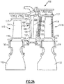
- Figure 2A shows selected portions of a section 100 of a gas turbine engine, such as a portion of the turbine section 28 of the gas turbine engine 20 of Figure 1 .
- the section 100 includes a vane section 102 having a stator vane 104 that has an airfoil shape and has a leading edge 105 and a trailing edge 106.
- the stator vane 104 extends between a radially inner platform 107 and a radially outer platform 108.
- “radially inner” and “radially outer” refer to the engine central longitudinal axis A.
- the vane section 102 is spaced axially away from rotor sections 110 with respect to the engine central longitudinal axis A.
- the rotor sections 110 each include a rotor disk 112 carrying one or more blades 114 extending from a platform 116 for rotation about the engine central longitudinal axis A.
- the rotor sections 110 also include a blade outer air seal 117 ("BOAS") situated radially outward of the blades 114.
- BOAS blade outer air seal
- the stator vane 104 includes an internal cavity 120 that extends radially outward from the radially inner platform 107 to the radially outer platform 108.
- a baffle 122 is a part that is disposed within the internal cavity 120 of the stator vane 104.
- the baffle 122 is a dual cavity baffle that defines a first baffle cavity 124 and an adjacent second baffle cavity 126 that are separated by a dividing wall 158.
- the baffle cavities 124, 126 extend from the radially inner platform 107 to the radially outer platform 108.
- the first baffle cavity 124 is situated proximate to the leading edge 105 of the stator vane 104
- the second baffle cavity 126 is situated proximate to the trailing edge 106 of the stator vane 104.
- FIG 2B is an enlarged schematic view of the stator vane 104 and baffle 122 of Figure 2A .
- the first baffle cavity 124 extends radially outward beyond the radially outer platform 108 and the second baffle cavity 126 to an impingement plate 130 that is spaced apart from the radially outer platform 108.
- the second baffle cavity 126 is spaced away from the impingement plate 130, and does not extend all the way to the impingement plate 130.
- the impingement plate 130 acts as a divider between a first outer diameter (OD) chamber 134 and a second OD chamber 135 that is radially inward of the first OD chamber 134.
- the impingement plate 130 and radially outer platform 108 at least partially define the second OD chamber 135.
- the first OD chamber 134 is in fluid communication with the first baffle cavity 124 and the second OD chamber 135, and the second OD chamber 135 is in fluid communication with the second baffle cavity 126 and is fluidly isolated from the first baffle cavity 124.
- the first and second baffle cavities 124, 126 include a respective first end 138A-B that is proximate to the radially outer platform 108, and also include a respective second end 140A-B that is proximate to the radially inner platform 107.
- the respective first ends 138A-B are opposite the respective second ends 140A-B.
- the first baffle cavity 124 opens to OD chamber 134 at its first end 138A and is closed at end 140A.
- the second baffle cavity 126 is open at both of its ends 138B, 140B.
- the second baffle cavity 126 opens to OD chamber 135 at its end 138B, and opens to an inner diameter (ID) chamber 144 at its end 140B.
- Figure 2B illustrates how the baffle cavities 124, 126 and impingement plate 130 provide for two distinct flow paths for cooling air that flows radially inward from a source 132.
- the first flow path is generally shown as 180
- the second flow path is generally shown as 182.
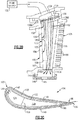
- cooling air is fluidly communicated from the source 132 into the first OD chamber 134, into the first baffle cavity 124, and then out sidewall impingement openings 150 (see Figure 2C and Figure 3 ) along a leading edge of the first baffle cavity 124 for impingement cooling of the stator vane 104.
- the cooling air in the first flow path 180 then travels axially through internal cavity 120 and exits out apertures 86 in the trailing edge 106 of stator vane 104 (see Figure 2B and Figure 2C ).
- cooling air is fluidly communicated from the source 132 into the first OD chamber 134, through the impingement plate 130 into the second OD chamber 135 where it contacts and cools the radially outer platform 108 (see Figure 5 ), and then through the second baffle cavity 126 into the ID chamber 144, and through an orifice 145 in an inner air seal 146.
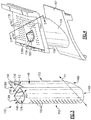
- an example baffle 122 is shown outside of the internal cavity 120.
- the respective ends 140A-B of the first baffle cavity 124 and second baffle cavity 126 are flush with each other, and the respective ends 138A-B of the first baffle cavity 124 and second baffle cavity 126 are radially offset from each other.
- the ends 138A-B are not coplanar.
- the ends 140A-B lie in a plane PI
- the end 138A lies in a plane P2
- the end 138B lies in a plane P3 that is offset from and not coplanar with the plane P2.
- the plane P2 is further radially outward than the plane P3.
- the radially inner ends 140A-B of the baffle 122 are offset and not flush with each other, and the radially outer ends 183A-B of the baffle 122 are also offset and not flush with each other.
- the first baffle cavity 124 is defined by a longitudinal sidewall 148 that extends along a leading edge 152 of the baffle 122 and the dividing wall 158.
- the second baffle cavity 126 is defined by the dividing wall 158 and a pair of second longitudinal sidewalls 149 that converge at a trailing edge 153 of the baffle 122.
- the dividing wall 158 separates the first baffle cavity 124 and second baffle cavity 126.
- Figure 3 shows a first quantity of sidewall impingement openings 150 disposed in sidewall 148 along a leading edge 152 of the baffle 122 between the opposing ends 138A, 140A of the first baffle cavity 124.
- the impingement openings 150 may be disposed anywhere in sidewall 148 (e.g., locations other than or in addition to the leading edge 152).
- the dividing wall 158 between first baffle cavity 124 and second baffle cavity 126 is free of impingement openings.
- the longitudinal sidewalls 149 of the second baffle cavity 126 are also free of sidewall impingement openings 150.
- one or both of the sidewalls 149 of the second baffle cavity 126 contain impingement openings 150 (e.g., along a trailing edge 153 of the baffle 122), but include a lower quantity than the sidewall 148.
- FIG 4 illustrates an example impingement plate 130 for the baffle 122.
- the impingement plate 130 includes a first opening 160 that opens to the first baffle cavity 124, and also includes a plurality of second openings 162 that open to the second OD chamber 135.
- the quantity of second openings 162 is greater than the quantity of first openings 160, and the second openings 162 are smaller than the first opening 160.
- the impingement plate 130 includes a single first opening 160 for the first baffle cavity 124, and that opening 160 is slightly larger than the first end 138A of the first baffle cavity 124.
- a profile 164 of the second baffle cavity 126 is shown in dotted lines.
- the impingement plate 130 is free of openings within the profile 164.
- other embodiments of impingement plate 130 may contain openings 162 within profile 164 of the second baffle cavity 126.
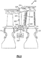
- Figure 5 illustrates a view of the stator vane 104 and impingement plate 130 taken along line D-D of Figure 4 .
- the plurality of second openings 162 open to the second OD chamber 135.
- the first cooling flow path 180 is provided to the interior of first baffle cavity 124 through opening 160 in the impingement plate 130.
- the second cooling flow path 182 passes through the openings 162 of the impingement plate 130 into the second OD chamber 135, where it cools the radially outer platform 108, and then enters the baffle cavity 126 from which it is communicated through the baffle cavity 126 into radially inner chamber 144, and then through an orifice 145 in inner air seal 146.
- the first end 138B of the second baffle cavity 126 is radially spaced apart from the impingement plate 130 and terminates proximate to the radially outer platform 108.
- a U-shaped collar 168 extends from the radially outer platform 108 to the impingement plate 130 and surrounds a portion of the first baffle cavity 124.
- the collar 168 includes ends 170 that terminate at the dividing wall 158.
- Figure 5 also illustrates how cooling air in the second flow path 182 contacts and cools the radially outer platform 108 before passing into the second baffle cavity 126.
- Figure 6 illustrates a view of the baffle 122 and stator vane 104 as shown in Figure 4 but with the impingement plate 130 removed.
- the collar 168 extends from the radially outer platform 108 and merges with a sidewall 184 of the OD chamber 135.
- the collar 168 is separate from sidewall 184, leaving a gap between the collar 168 and sidewall 184.
- baffled vane cooling designs take a single source of cooling air and use it to cool a radially outer platform, provide airfoil cooling, and provide vane through-flow. Because this air is used to do three things, vane design is constrained.
- the arrangements proposed herein provide for a dual-cavity baffle 122 that is paired with impingement plate 130 that allows supply air to be separated into air that is used to cool the stator vane 104 (flow 180) and through-flow air that is used to cool the radially outer platform 108 (flow 182).
- the first flow 180 avoids picking up heat and losing pressure, and is therefore able to provide better cooling to the stator vane 104.
- This provides for increased transfer of heat away from the stator vane 104 as compared to a conventional baffle, reduced part temperatures, and improved part life.
- Figure 7 illustrates another example baffle 222 in which second baffle cavity 226 extends further radially outward than the first baffle cavity 224.
- the respective ends 240A-B of the first baffle cavity 224 and second baffle cavity 226 are flush with each other, and the respective ends 238A-B of the first baffle cavity 224 and second baffle cavity 226 are radially offset from each other.
- the first baffle cavity 224 is closed at its end 240A and the second baffle cavity 226 is open at its end 240B.
- FIG 8 illustrates an example impingement plate 230 for the baffle 222 of Figure 7 .
- the impingement plate 230 includes a first opening 260 that opens to the second baffle cavity 226, and also includes a plurality of second openings 262 that open to the second OD chamber 135.
- the quantity of second openings 262 is greater than the quantity of first openings 260, and the second openings 262 are smaller than the first opening 260.
- the impingement plate 230 includes a single first opening 260 for the second baffle cavity 226 that is slightly larger than the first end 238B of the second baffle cavity 226.
- a profile 264 of the first baffle cavity 224 is shown in dotted lines.
- the impingement plate 230 is free of openings within the profile 264. This arrangement provides for cooler and higher pressure air for through-flow into the second baffle cavity 226.
- Figure 9 illustrates another example section 300 of a gas turbine engine in which an impingement plate 330 is disposed radially inward of both a baffle 322 and an inner diameter platform 307, and a source of cooling air 332 communicates cooling air radially outward.
- a baffle 322 defines a first baffle cavity 324 and a second baffle cavity 326.
- the first baffle cavity 324 extends radially inward beyond the radially inner platform 307 to the impingement plate 330, and the second baffle cavity 326 is spaced apart from impingement plate 330 and terminates proximate to the radially inner platform 307.
- the source 332 is in fluid communication with the baffle cavities 324, 326.
- the second baffle cavity 326 provides for through-flow that passes to OD chamber 334, while the first baffle cavity 324 is closed at an end proximate to OD chamber 334, and fluidly communicates cooling air from source 332 through sidewall impingement openings along a leading edge of the first baffle cavity 324 for impingement cooling of the stator vane 104.
- the first baffle cavity 324 and second baffle cavity 326 are flush at their respective radially outer ends.
- the second baffle cavity 326 that extends to the impingement plate 330 and the first baffle cavity 324 that is spaced apart from the impingement plate 330 and terminates proximate to the radially inner platform 307.
Landscapes
- Engineering & Computer Science (AREA)
- Mechanical Engineering (AREA)
- General Engineering & Computer Science (AREA)
- Chemical & Material Sciences (AREA)
- Combustion & Propulsion (AREA)
- Turbine Rotor Nozzle Sealing (AREA)
Abstract
Description
- This application relates to cooling a component of a gas turbine engine, and more particularly to a dual cavity baffle for cooling a component.
- Gas turbine engines are known and typically include a fan delivering air for propulsion and for cooling components. The fan also delivers air into a compressor where air is compressed and delivered into a combustor. The air is mixed with fuel and ignited. Products of this combustion pass downstream over turbine rotors driving them to rotate. The turbine rotors, in turn, rotate compressor rotors and the fan rotor.
- Stator vanes are positioned adjacent to turbine blades in a gas turbine and are subject to high temperatures. In one known cooling scheme for a stator vane, a baffle defines a single baffle cavity that is disposed within an interior cavity of the stator vane, and cooling air is directed outwards from within the single baffle cavity to the interior cavity.
- A component for a gas turbine engine according to example of the present disclosure includes a body that has an airfoil extending between a radially inner platform and a radially outer platform, and that has an internal cavity within the airfoil. A baffle is disposed within the internal cavity. The baffle defines first and second baffle cavities that are separated by a baffle dividing wall extending between the radially inner platform and the radially outer platform. An impingement plate is spaced apart from one of the radially inner and outer platforms, includes a first opening that provides fluid communication between a first chamber and the first baffle cavity, and includes a plurality of second openings that are smaller than the first opening and provide fluid communication between the first chamber and the second baffle cavity via a second chamber.
- In an embodiment of the foregoing embodiment, the first baffle cavity extends in a radial direction beyond the one of the inner and outer diameter platforms to the impingement plate at a first end, and a terminal end of the second baffle cavity proximate to the one of the radially inner and outer platforms is spaced apart from the impingement plate.
- In a further embodiment of any of the foregoing embodiments, the second baffle cavity is open at both of its opposing ends, and the first baffle cavity is closed at a second end that is opposite the first end of the first baffle cavity.
- In a further embodiment of any of the foregoing embodiments, the first baffle cavity is situated proximate to a leading edge of the airfoil, and the second baffle cavity is situated proximate to a trailing edge of the airfoil.
- In a further embodiment of any of the foregoing embodiments, the first baffle cavity is situated proximate to a trailing edge of the airfoil, and the second baffle cavity is situated proximate to a leading edge of the airfoil.
- In a further embodiment of any of the foregoing embodiments, a U-shaped collar extends between the one of the radially inner and outer platforms and the impingement plate and surrounds a portion of the baffle.
- In a further embodiment of any of the foregoing embodiments, the collar comprises ends that terminate at the baffle dividing wall.
- In a further embodiment of any of the foregoing embodiments, the baffle dividing wall is free of openings between the first and second cavities.
- In a further embodiment of any of the foregoing embodiments, the second chamber is fluidly isolated from the first baffle cavity.
- In a further embodiment of any of the foregoing embodiments, the impingement plate is free of openings within a profile of the second baffle cavity.
- In a further embodiment of any of the foregoing embodiments, one of the first and second baffle cavities is disposed along a leading edge of the baffle and includes a plurality of sidewall openings that are disposed between the radially inner and radially outer platforms and that open to the internal cavity for directing cooling air from within the one of the first and second cavities to the internal cavity.
- In a further embodiment of any of the foregoing embodiments, a second of the first and second cavities is free of sidewall openings.
- In a further embodiment of any of the foregoing embodiments, a second of the first and second cavities comprises a quantity of sidewall openings that is less than a quantity of sidewall openings of the one of the first and second cavities.
- In a further embodiment of any of the foregoing embodiments, the one of the radially inner and outer platforms is the radially outer platform.
- In a further embodiment of any of the foregoing embodiments, the one of the radially inner and outer platforms is the radially inner platform.
- In a further embodiment of any of the foregoing embodiments, the body having an airfoil includes a stator vane.
- A gas turbine engine according to an example of the present disclosure includes a compressor section, a combustor section in fluid communication with the compressor section, and a turbine section in fluid communication with the combustor section. The turbine section has an engine component that extends between a radially inner platform and a radially outer platform and includes an airfoil that has an internal cavity. A baffle is disposed within the internal cavity. The baffle defines first and second baffle cavities that are separated by a baffle dividing wall that extends between the radially inner platform and the radially outer platform. An impingement plate spaced apart from one of the radially inner and outer platforms, includes a first opening that provides fluid communication between a first chamber and the first baffle cavity, and includes a plurality of second openings that are smaller than the first opening and provide fluid communication between the first chamber and the second baffle cavity via a second chamber. The first chamber is in fluid communication with a source of cooling air.
- In an embodiment of the foregoing embodiment, the first baffle cavity extends in a radial direction beyond the one of the inner and outer diameter platforms to the impingement plate at a first end, and a terminal end of the second baffle cavity proximate to the one of the radially inner and outer platforms is spaced apart from the impingement plate.
- In a further embodiment of any of the foregoing embodiments, one of the first and second baffle cavities is disposed along a leading edge of the baffle and comprises a plurality of sidewall openings that are disposed between the radially inner and outer platforms and that open to the internal cavity for directing cooling air from within the one of the first and second cavities to the internal cavity.
- In a further embodiment of any of the foregoing embodiments, a U-shaped collar extends between the one of the radially inner and outer platforms and the impingement plate and surrounds a portion of the baffle.
- The embodiments, examples, and alternatives of the preceding paragraphs, the claims, or the following description and drawings, including any of their various aspects or respective individual features, may be taken independently or in any combination. Features described in connection with one embodiment are applicable to all embodiments, unless such features are incompatible.
-
-
Figure 1 is a schematic view of an example gas turbine engine. -
Figures 2A-B are schematic views of an example section of a gas turbine engine. -
Figure 2C is a cross-sectional view of a stator vane -
Figure 3 illustrates an example baffle. -
Figure 4 illustrates the baffle ofFigure 3 within a stator vane, and an example impingement plate for the baffle. -
Figure 5 illustrates a view of a stator vane and impingement plate taken along line D-D ofFigure 4 . -
Figure 6 illustrates a view of a baffle and stator vane ofFigure 4 with the impingement plate removed. -
Figure 7 illustrates another example baffle. -
Figure 8 illustrates an example impingement plate for the baffle ofFigure 7 . -
Figure 9 is a schematic view of another example section of a gas turbine engine. -
Figure 1 schematically illustrates agas turbine engine 20. Thegas turbine engine 20 is disclosed herein as a two-spool turbofan that generally incorporates afan section 22, acompressor section 24, acombustor section 26, and aturbine section 28. Alternative engines might include an augmentor section (not shown) among other systems or features. Thefan section 22 drives air along a bypass flow path B in a bypass duct defined within anacelle 15, and also drives air along a core flow path C for compression and communication into thecombustor section 26 then expansion through theturbine section 28. Although depicted as a two-spool turbofan gas turbine engine in the disclosed non-limiting embodiment, it should be understood that the concepts described herein are not limited to use with two-spool turbofans as the teachings may be applied to other types of turbine engines including three-spool architectures. - The
exemplary engine 20 generally includes alow speed spool 30 and ahigh speed spool 32 mounted for rotation about an engine central longitudinal axis A relative to an enginestatic structure 36 viaseveral bearing systems 38. It should be understood thatvarious bearing systems 38 at various locations may alternatively or additionally be provided, and the location ofbearing systems 38 may be varied as appropriate to the application. - The
low speed spool 30 generally includes aninner shaft 40 that interconnects afan 42, a first (or low)pressure compressor 44 and a first (or low)pressure turbine 46. Theinner shaft 40 is connected to thefan 42 through a speed change mechanism, which in exemplarygas turbine engine 20 is illustrated as a gearedarchitecture 48 to drive thefan 42 at a lower speed than thelow speed spool 30. Thehigh speed spool 32 includes anouter shaft 50 that interconnects a second (or high)pressure compressor 52 and a second (or high)pressure turbine 54. Acombustor 56 is arranged inexemplary gas turbine 20 between thehigh pressure compressor 52 and thehigh pressure turbine 54. Amid-turbine frame 57 of the enginestatic structure 36 is arranged generally between thehigh pressure turbine 54 and thelow pressure turbine 46. Themid-turbine frame 57 further supports bearingsystems 38 in theturbine section 28. Theinner shaft 40 and theouter shaft 50 are concentric and rotate via bearingsystems 38 about the engine central longitudinal axis A which is collinear with their longitudinal axes. - The core airflow is compressed by the
low pressure compressor 44 then thehigh pressure compressor 52, mixed and burned with fuel in thecombustor 56, then expanded over thehigh pressure turbine 54 andlow pressure turbine 46. Themid-turbine frame 57 includesairfoils 59 which are in the core airflow path C. Theturbines low speed spool 30 andhigh speed spool 32 in response to the expansion. It will be appreciated that each of the positions of thefan section 22,compressor section 24,combustor section 26,turbine section 28, and fandrive gear system 48 may be varied. For example,gear system 48 may be located aft ofcombustor section 26 or even aft ofturbine section 28, andfan section 22 may be positioned forward or aft of the location ofgear system 48. - The
engine 20 in one example is a high-bypass geared aircraft engine. In a further example, theengine 20 bypass ratio is greater than about six (6), with an example embodiment being greater than about ten (10), the gearedarchitecture 48 is an epicyclic gear train, such as a planetary gear system or other gear system, with a gear reduction ratio of greater than about 2.3 and thelow pressure turbine 46 has a pressure ratio that is greater than about five. In one disclosed embodiment, theengine 20 bypass ratio is greater than about ten (10:1), the fan diameter is significantly larger than that of thelow pressure compressor 44, and thelow pressure turbine 46 has a pressure ratio that is greater than about five 5:1.Low pressure turbine 46 pressure ratio is pressure measured prior to inlet oflow pressure turbine 46 as related to the pressure at the outlet of thelow pressure turbine 46 prior to an exhaust nozzle. The gearedarchitecture 48 may be an epicycle gear train, such as a planetary gear system or other gear system, with a gear reduction ratio of greater than about 2.3:1. It should be understood, however, that the above parameters are only exemplary of one embodiment of a geared architecture engine and that the present invention is applicable to other gas turbine engines including direct drive turbofans.
A significant amount of thrust is provided by the bypass flow B due to the high bypass ratio. Thefan section 22 of theengine 20 is designed for a particular flight condition -- typically cruise at about 0.8 Mach and about 35,000 feet (10,668 meters). The flight condition of 0.8 Mach and 35,000 ft (10,668 meters), with the engine at its best fuel consumption - also known as "bucket cruise Thrust Specific Fuel Consumption ('TSFC')" - is the industry standard parameter of lbm of fuel being burned divided by lbf of thrust the engine produces at that minimum point. "Low fan pressure ratio" is the pressure ratio across the fan blade alone, without a Fan Exit Guide Vane ("FEGV") system. The low fan pressure ratio as disclosed herein according to one non-limiting embodiment is less than about 1.45. "Low corrected fan tip speed" is the actual fan tip speed in ft/sec divided by an industry standard temperature correction of [(Tram °R) / (518.7 °R)]0.5 (where R = κ x 9/5). The "Low corrected fan tip speed" as disclosed herein according to one non-limiting embodiment is less than about 1150 ft / second (350.5 meters/second). -
Figure 2A shows selected portions of asection 100 of a gas turbine engine, such as a portion of theturbine section 28 of thegas turbine engine 20 ofFigure 1 . In this disclosure, forreference numerals 100 and beyond, like reference numerals designate like elements where appropriate, and reference numerals with the addition of one-hundred or multiples thereof designate modified elements that are understood to incorporate the same features and benefits of the corresponding original elements. In this example, thesection 100 includes avane section 102 having astator vane 104 that has an airfoil shape and has aleading edge 105 and a trailingedge 106. Thestator vane 104 extends between a radiallyinner platform 107 and a radiallyouter platform 108. In this disclosure, "radially inner" and "radially outer" refer to the engine central longitudinal axis A. - The
vane section 102 is spaced axially away fromrotor sections 110 with respect to the engine central longitudinal axis A. Therotor sections 110 each include arotor disk 112 carrying one ormore blades 114 extending from aplatform 116 for rotation about the engine central longitudinal axis A. In the example ofFigure 2A , therotor sections 110 also include a blade outer air seal 117 ("BOAS") situated radially outward of theblades 114. - The
stator vane 104 includes aninternal cavity 120 that extends radially outward from the radiallyinner platform 107 to the radiallyouter platform 108. Abaffle 122 is a part that is disposed within theinternal cavity 120 of thestator vane 104. Thebaffle 122 is a dual cavity baffle that defines afirst baffle cavity 124 and an adjacentsecond baffle cavity 126 that are separated by a dividingwall 158. The baffle cavities 124, 126 extend from the radiallyinner platform 107 to the radiallyouter platform 108. Thefirst baffle cavity 124 is situated proximate to theleading edge 105 of thestator vane 104, and thesecond baffle cavity 126 is situated proximate to the trailingedge 106 of thestator vane 104. -
Figure 2B is an enlarged schematic view of thestator vane 104 and baffle 122 ofFigure 2A . As shown inFigures 2A-B , thefirst baffle cavity 124 extends radially outward beyond the radiallyouter platform 108 and thesecond baffle cavity 126 to animpingement plate 130 that is spaced apart from the radiallyouter platform 108. Thesecond baffle cavity 126 is spaced away from theimpingement plate 130, and does not extend all the way to theimpingement plate 130. - The
impingement plate 130 acts as a divider between a first outer diameter (OD)chamber 134 and asecond OD chamber 135 that is radially inward of thefirst OD chamber 134. Theimpingement plate 130 and radiallyouter platform 108 at least partially define thesecond OD chamber 135. In one example, thefirst OD chamber 134 is in fluid communication with thefirst baffle cavity 124 and thesecond OD chamber 135, and thesecond OD chamber 135 is in fluid communication with thesecond baffle cavity 126 and is fluidly isolated from thefirst baffle cavity 124. - The first and
second baffle cavities first end 138A-B that is proximate to the radiallyouter platform 108, and also include a respectivesecond end 140A-B that is proximate to the radiallyinner platform 107. The respective first ends 138A-B are opposite the respective second ends 140A-B. - The
first baffle cavity 124 opens to ODchamber 134 at itsfirst end 138A and is closed atend 140A. Thesecond baffle cavity 126 is open at both of itsends second baffle cavity 126 opens to ODchamber 135 at itsend 138B, and opens to an inner diameter (ID)chamber 144 at itsend 140B. -
Figure 2B illustrates how thebaffle cavities impingement plate 130 provide for two distinct flow paths for cooling air that flows radially inward from asource 132. The first flow path is generally shown as 180, and the second flow path is generally shown as 182. - In the
first flow path 180, cooling air is fluidly communicated from thesource 132 into thefirst OD chamber 134, into thefirst baffle cavity 124, and then out sidewall impingement openings 150 (seeFigure 2C andFigure 3 ) along a leading edge of thefirst baffle cavity 124 for impingement cooling of thestator vane 104. The cooling air in thefirst flow path 180 then travels axially throughinternal cavity 120 and exits outapertures 86 in the trailingedge 106 of stator vane 104 (seeFigure 2B and Figure 2C ). - In the
second flow path 182, cooling air is fluidly communicated from thesource 132 into thefirst OD chamber 134, through theimpingement plate 130 into thesecond OD chamber 135 where it contacts and cools the radially outer platform 108 (seeFigure 5 ), and then through thesecond baffle cavity 126 into theID chamber 144, and through anorifice 145 in aninner air seal 146. - Referring now to
Figure 3 , anexample baffle 122 is shown outside of theinternal cavity 120. As shown inFigure 3 , the respective ends 140A-B of thefirst baffle cavity 124 andsecond baffle cavity 126 are flush with each other, and the respective ends 138A-B of thefirst baffle cavity 124 andsecond baffle cavity 126 are radially offset from each other. In one example, by being "offset" from each other, the ends 138A-B are not coplanar. In one example, the ends 140A-B lie in a plane PI, theend 138A lies in a plane P2, and theend 138B lies in a plane P3 that is offset from and not coplanar with the plane P2. In one example, when thebaffle 122 is assembled into theinternal cavity 120 of thestator vane 104, the plane P2 is further radially outward than the plane P3. In one example, the radially inner ends 140A-B of thebaffle 122 are offset and not flush with each other, and the radially outer ends 183A-B of thebaffle 122 are also offset and not flush with each other. - The
first baffle cavity 124 is defined by alongitudinal sidewall 148 that extends along aleading edge 152 of thebaffle 122 and the dividingwall 158. Thesecond baffle cavity 126 is defined by the dividingwall 158 and a pair of secondlongitudinal sidewalls 149 that converge at a trailingedge 153 of thebaffle 122. The dividingwall 158 separates thefirst baffle cavity 124 andsecond baffle cavity 126. -
Figure 3 shows a first quantity ofsidewall impingement openings 150 disposed insidewall 148 along aleading edge 152 of thebaffle 122 between the opposing ends 138A, 140A of thefirst baffle cavity 124. In various embodiments, theimpingement openings 150 may be disposed anywhere in sidewall 148 (e.g., locations other than or in addition to the leading edge 152). In one example, the dividingwall 158 betweenfirst baffle cavity 124 andsecond baffle cavity 126 is free of impingement openings. In the example ofFigure 3 , thelongitudinal sidewalls 149 of thesecond baffle cavity 126 are also free ofsidewall impingement openings 150. In other embodiments, one or both of thesidewalls 149 of thesecond baffle cavity 126 contain impingement openings 150 (e.g., along a trailingedge 153 of the baffle 122), but include a lower quantity than thesidewall 148. -
Figure 4 illustrates anexample impingement plate 130 for thebaffle 122. As shown inFigure 4 , theimpingement plate 130 includes afirst opening 160 that opens to thefirst baffle cavity 124, and also includes a plurality ofsecond openings 162 that open to thesecond OD chamber 135. The quantity ofsecond openings 162 is greater than the quantity offirst openings 160, and thesecond openings 162 are smaller than thefirst opening 160. - In the example of
Figure 4 , theimpingement plate 130 includes a singlefirst opening 160 for thefirst baffle cavity 124, and that opening 160 is slightly larger than thefirst end 138A of thefirst baffle cavity 124. Aprofile 164 of thesecond baffle cavity 126 is shown in dotted lines. In the example ofFigure 4 , theimpingement plate 130 is free of openings within theprofile 164. However, other embodiments ofimpingement plate 130 may containopenings 162 withinprofile 164 of thesecond baffle cavity 126. -
Figure 5 illustrates a view of thestator vane 104 andimpingement plate 130 taken along line D-D ofFigure 4 . As shown inFigure 5 , the plurality ofsecond openings 162 open to thesecond OD chamber 135. The firstcooling flow path 180 is provided to the interior offirst baffle cavity 124 throughopening 160 in theimpingement plate 130. The secondcooling flow path 182 passes through theopenings 162 of theimpingement plate 130 into thesecond OD chamber 135, where it cools the radiallyouter platform 108, and then enters thebaffle cavity 126 from which it is communicated through thebaffle cavity 126 into radiallyinner chamber 144, and then through anorifice 145 ininner air seal 146. - As shown in
Figure 5 , thefirst end 138B of thesecond baffle cavity 126 is radially spaced apart from theimpingement plate 130 and terminates proximate to the radiallyouter platform 108. AU-shaped collar 168 extends from the radiallyouter platform 108 to theimpingement plate 130 and surrounds a portion of thefirst baffle cavity 124. Thecollar 168 includesends 170 that terminate at the dividingwall 158.Figure 5 also illustrates how cooling air in thesecond flow path 182 contacts and cools the radiallyouter platform 108 before passing into thesecond baffle cavity 126. -
Figure 6 illustrates a view of thebaffle 122 andstator vane 104 as shown inFigure 4 but with theimpingement plate 130 removed. In the example ofFigure 6 , thecollar 168 extends from the radiallyouter platform 108 and merges with asidewall 184 of theOD chamber 135. In another example, thecollar 168 is separate fromsidewall 184, leaving a gap between thecollar 168 andsidewall 184. - Traditional baffled vane cooling designs take a single source of cooling air and use it to cool a radially outer platform, provide airfoil cooling, and provide vane through-flow. Because this air is used to do three things, vane design is constrained. The arrangements proposed herein provide for a dual-
cavity baffle 122 that is paired withimpingement plate 130 that allows supply air to be separated into air that is used to cool the stator vane 104 (flow 180) and through-flow air that is used to cool the radially outer platform 108 (flow 182). Because theflow 180 passes through alarge impingement opening 160 in the impingement plate and not through a plurality of thesmaller openings 162, thefirst flow 180 avoids picking up heat and losing pressure, and is therefore able to provide better cooling to thestator vane 104. This allows the cooling air that is communicated into thefirst baffle cavity 124 withflow 180 for cooling thestator vane 104 to be cooler and of a higher pressure than the cooling air that is communicated into the second baffle cavity withflow 182 for through-flow. This provides for increased transfer of heat away from thestator vane 104 as compared to a conventional baffle, reduced part temperatures, and improved part life. -
Figure 7 illustrates anotherexample baffle 222 in whichsecond baffle cavity 226 extends further radially outward than thefirst baffle cavity 224. The respective ends 240A-B of thefirst baffle cavity 224 andsecond baffle cavity 226 are flush with each other, and the respective ends 238A-B of thefirst baffle cavity 224 andsecond baffle cavity 226 are radially offset from each other. In one example, thefirst baffle cavity 224 is closed at itsend 240A and thesecond baffle cavity 226 is open at itsend 240B. -
Figure 8 illustrates anexample impingement plate 230 for thebaffle 222 ofFigure 7 . Theimpingement plate 230 includes afirst opening 260 that opens to thesecond baffle cavity 226, and also includes a plurality ofsecond openings 262 that open to thesecond OD chamber 135. The quantity ofsecond openings 262 is greater than the quantity offirst openings 260, and thesecond openings 262 are smaller than thefirst opening 260. In the example ofFigure 8 , theimpingement plate 230 includes a singlefirst opening 260 for thesecond baffle cavity 226 that is slightly larger than thefirst end 238B of thesecond baffle cavity 226. - A
profile 264 of thefirst baffle cavity 224 is shown in dotted lines. In the example ofFigure 8 , theimpingement plate 230 is free of openings within theprofile 264. This arrangement provides for cooler and higher pressure air for through-flow into thesecond baffle cavity 226. -
Figure 9 illustrates anotherexample section 300 of a gas turbine engine in which animpingement plate 330 is disposed radially inward of both abaffle 322 and aninner diameter platform 307, and a source of coolingair 332 communicates cooling air radially outward. - A
baffle 322 defines afirst baffle cavity 324 and asecond baffle cavity 326. Thefirst baffle cavity 324 extends radially inward beyond the radiallyinner platform 307 to theimpingement plate 330, and thesecond baffle cavity 326 is spaced apart fromimpingement plate 330 and terminates proximate to the radiallyinner platform 307. Thesource 332 is in fluid communication with thebaffle cavities second baffle cavity 326 provides for through-flow that passes toOD chamber 334, while thefirst baffle cavity 324 is closed at an end proximate toOD chamber 334, and fluidly communicates cooling air fromsource 332 through sidewall impingement openings along a leading edge of thefirst baffle cavity 324 for impingement cooling of thestator vane 104. In one example, thefirst baffle cavity 324 andsecond baffle cavity 326 are flush at their respective radially outer ends. - In a further example, it is the
second baffle cavity 326 that extends to theimpingement plate 330 and thefirst baffle cavity 324 that is spaced apart from theimpingement plate 330 and terminates proximate to the radiallyinner platform 307. In one such example, it is thesecond baffle cavity 326 that provides for through-flow radially outward to theOD chamber 334. - Although example embodiments have been disclosed, a worker of ordinary skill in this art would recognize that certain modifications would come within the scope of this disclosure. For that reason, the following claims should be studied to determine the scope and content of this disclosure.
Claims (15)
- A component for a gas turbine engine comprising:a body (104) having an airfoil extending between a radially inner platform (107;307) and a radially outer platform (108;308), and having an internal cavity (120) within the airfoil;a baffle (122;222;322) disposed within the internal cavity (120), the baffle (122;222;322) defining first and second baffle cavities (124,126;224,226;324,326) that are separated by a baffle dividing wall (158) extending between the radially inner platform (107;307) and the radially outer platform (108;308); andan impingement plate (130;230;330) spaced apart from one of the radially inner and outer platforms (107,108;307,308), the impingement plate (130;230;330) comprising a first opening (160;260) that provides fluid communication between a first chamber (134) and the first baffle cavity, and a plurality of second openings (162;262) that are smaller than the first opening (160;260) and provide fluid communication between the first chamber (134) and the second baffle cavity via a second chamber (135).
- The component of claim 1, wherein the first baffle cavity extends in a radial direction beyond said one of the inner and outer diameter platforms (107,108;307,308) to the impingement plate (130;230;330) at a first end, and a terminal end of the second baffle cavity proximate to said one of the radially inner and outer platforms (107,108;307,308) is spaced apart from the impingement plate (130;230;330).
- The component of claim 2, wherein the second baffle cavity (126;226;326) is open at both of its opposing ends (138B,140B;238B,240B), and the first baffle cavity (124;224;334) is closed at a second end (140A;240A) that is opposite the first end of the first baffle cavity (124;224;334).
- The component of claim 1, 2 or 3, wherein said first baffle cavity (124;224;324) is situated proximate to a leading edge (105) of said airfoil, and said second baffle cavity (126;226;326) is situated proximate to a trailing edge (106) of said airfoil.
- The component of claim 1 or 2, wherein said first baffle cavity (126;226;326) is situated proximate to a trailing edge (106) of said airfoil, and said second baffle cavity (124;224;324) is situated proximate to a leading edge (105) of said airfoil.
- The component of claim 1, wherein one of the first and second baffle cavities (124;224;324) is disposed along a leading edge (152) of the baffle (122;222;322) and comprises a plurality of sidewall openings (150) that are disposed between the radially inner and radially outer platforms (107,108;307,308) and that open to the internal cavity (120) for directing cooling air from within said one of the first and second cavities (124;224;324) to the internal cavity (120).
- The component of claim 6, wherein a second of the first and second cavities (126;226;326) is free of sidewall openings.
- The component of claim 6, wherein a second of the first and second cavities (126;226;326) comprises a quantity of sidewall openings that is less than a quantity of sidewall openings of said one of the first and second cavities (124;224;324).
- The component of any preceding claim, comprising a U-shaped collar (168) extending between said one of the radially inner and outer platforms (107,108;307,308) and said impingement plate (130;230;330) and surrounding a portion of the baffle (122;222;322).
- The component of claim 9, wherein the collar (168) comprises ends (170) that terminate at the baffle dividing wall (158).
- The component of any preceding claim, wherein the baffle dividing wall (158) is free of openings between the first and second cavities (124,126;224,226;324,326).
- The component of any preceding claim, wherein the second chamber (135) is fluidly isolated from the first baffle cavity.
- The component of any preceding claim, wherein the impingement plate (130;230;330) is free of openings within a profile (164;264) of the second baffle cavity.
- The component of any preceding claim, wherein said body (104) having an airfoil comprises a stator vane.
- A gas turbine engine comprising:a compressor section (24);a combustor section (26) in fluid communication with the compressor section (24);a turbine section (28) in fluid communication with the combustor section (26), the turbine section (28) including the component of any preceding claim, wherein the first chamber (134) is in fluid communication with a source of cooling air (132;332).
Applications Claiming Priority (1)
| Application Number | Priority Date | Filing Date | Title |
|---|---|---|---|
| US15/884,500 US10415428B2 (en) | 2018-01-31 | 2018-01-31 | Dual cavity baffle |
Publications (2)
| Publication Number | Publication Date |
|---|---|
| EP3543464A1 true EP3543464A1 (en) | 2019-09-25 |
| EP3543464B1 EP3543464B1 (en) | 2020-10-14 |
Family
ID=65243445
Family Applications (1)
| Application Number | Title | Priority Date | Filing Date |
|---|---|---|---|
| EP19154303.2A Active EP3543464B1 (en) | 2018-01-31 | 2019-01-29 | Dual cavity baffle |
Country Status (2)
| Country | Link |
|---|---|
| US (1) | US10415428B2 (en) |
| EP (1) | EP3543464B1 (en) |
Cited By (1)
| Publication number | Priority date | Publication date | Assignee | Title |
|---|---|---|---|---|
| BE1029380A1 (en) | 2021-05-05 | 2022-12-02 | Decospan | PROCEDURE FOR TREATMENT OF WOODEN PANELS |
Families Citing this family (9)
| Publication number | Priority date | Publication date | Assignee | Title |
|---|---|---|---|---|
| US20190234235A1 (en) * | 2018-01-31 | 2019-08-01 | United Technologies Corporation | Vane flow diverter |
| US10724387B2 (en) * | 2018-11-08 | 2020-07-28 | Raytheon Technologies Corporation | Continuation of a shear tube through a vane platform for structural support |
| US10711620B1 (en) * | 2019-01-14 | 2020-07-14 | General Electric Company | Insert system for an airfoil and method of installing same |
| US10900362B2 (en) * | 2019-01-14 | 2021-01-26 | General Electric Company | Insert system for an airfoil and method of installing same |
| US11268392B2 (en) | 2019-10-28 | 2022-03-08 | Rolls-Royce Plc | Turbine vane assembly incorporating ceramic matrix composite materials and cooling |
| US11415006B2 (en) | 2020-09-17 | 2022-08-16 | Raytheon Technologies Corporation | CMC vane with support spar and baffle |
| US11359497B1 (en) * | 2020-12-21 | 2022-06-14 | Raytheon Technologies Corporation | Vane with baffle and recessed spar |
| US20240410284A1 (en) * | 2023-06-07 | 2024-12-12 | Raytheon Technologies Corporation | Turbine vane baffle chimney |
| US12546227B2 (en) * | 2024-02-09 | 2026-02-10 | Rtx Corporation | Cooling nozzle vanes of a turbine engine |
Citations (4)
| Publication number | Priority date | Publication date | Assignee | Title |
|---|---|---|---|---|
| US5207556A (en) * | 1992-04-27 | 1993-05-04 | General Electric Company | Airfoil having multi-passage baffle |
| EP1452690A2 (en) * | 2003-02-27 | 2004-09-01 | General Electric Company | Gas turbine engine turbine nozzle bifurcated impingement baffle |
| EP2927430A1 (en) * | 2014-04-04 | 2015-10-07 | United Technologies Corporation | Stator vane with a cooled platform for a gas turbine engine |
| EP3184750A1 (en) * | 2015-12-21 | 2017-06-28 | United Technologies Corporation | Impingement cooling baffle |
Family Cites Families (6)
| Publication number | Priority date | Publication date | Assignee | Title |
|---|---|---|---|---|
| FR2692318B1 (en) * | 1992-06-11 | 1994-08-19 | Snecma | Fixed blowing of hot gas distribution from a turbo-machine. |
| US6514046B1 (en) * | 2000-09-29 | 2003-02-04 | Siemens Westinghouse Power Corporation | Ceramic composite vane with metallic substructure |
| US7921654B1 (en) * | 2007-09-07 | 2011-04-12 | Florida Turbine Technologies, Inc. | Cooled turbine stator vane |
| EP2469029A1 (en) | 2010-12-22 | 2012-06-27 | Siemens Aktiengesellschaft | Impingement cooling of gas turbine blades or vanes |
| EP2626519A1 (en) * | 2012-02-09 | 2013-08-14 | Siemens Aktiengesellschaft | Turbine assembly, corresponding impingement cooling tube and gas turbine engine |
| EP2706195A1 (en) | 2012-09-05 | 2014-03-12 | Siemens Aktiengesellschaft | Impingement tube for gas turbine vane with a partition wall |
-
2018
- 2018-01-31 US US15/884,500 patent/US10415428B2/en active Active
-
2019
- 2019-01-29 EP EP19154303.2A patent/EP3543464B1/en active Active
Patent Citations (4)
| Publication number | Priority date | Publication date | Assignee | Title |
|---|---|---|---|---|
| US5207556A (en) * | 1992-04-27 | 1993-05-04 | General Electric Company | Airfoil having multi-passage baffle |
| EP1452690A2 (en) * | 2003-02-27 | 2004-09-01 | General Electric Company | Gas turbine engine turbine nozzle bifurcated impingement baffle |
| EP2927430A1 (en) * | 2014-04-04 | 2015-10-07 | United Technologies Corporation | Stator vane with a cooled platform for a gas turbine engine |
| EP3184750A1 (en) * | 2015-12-21 | 2017-06-28 | United Technologies Corporation | Impingement cooling baffle |
Cited By (1)
| Publication number | Priority date | Publication date | Assignee | Title |
|---|---|---|---|---|
| BE1029380A1 (en) | 2021-05-05 | 2022-12-02 | Decospan | PROCEDURE FOR TREATMENT OF WOODEN PANELS |
Also Published As
| Publication number | Publication date |
|---|---|
| US20190234236A1 (en) | 2019-08-01 |
| EP3543464B1 (en) | 2020-10-14 |
| US10415428B2 (en) | 2019-09-17 |
Similar Documents
| Publication | Publication Date | Title |
|---|---|---|
| EP3543464B1 (en) | Dual cavity baffle | |
| US11035236B2 (en) | Baffle for a component of a gas turbine engine | |
| EP3060760B1 (en) | Airfoil with skin core cooling | |
| EP3091186B1 (en) | Turbine engine component including an axially aligned skin core passage interrupted by a pedestal | |
| US20190234235A1 (en) | Vane flow diverter | |
| EP4230842A2 (en) | Airfoil with rib having connector arms | |
| EP3030771A1 (en) | Diffuser case mixing chamber for a turbine engine | |
| EP3150800B1 (en) | Airfoil baffle with wedge region | |
| US20210054746A1 (en) | Airfoil with ribs having connector arms and apertures defining a cooling circuit | |
| EP2927429B1 (en) | Gas turbine engine component with flow separating rib | |
| EP4317650A1 (en) | Asymmetric heat transfer member fillet to direct cooling flow | |
| US10677091B2 (en) | Airfoil with sealed baffle | |
| US20180038236A1 (en) | Gas turbine engine stator vane baffle arrangement | |
| EP3508693B1 (en) | Segregated cooling air passages for turbine vane | |
| EP3450697B1 (en) | Vane cluster and corresponding gas turbine engine | |
| EP3556997B1 (en) | Blade with inlet orifice on aft face of root | |
| US20160326909A1 (en) | Gas turbine engine component with separation rib for cooling passages | |
| EP2977557B1 (en) | Cooled airfoil structure and corresponding cooling method | |
| EP3581762B1 (en) | Platform cooling arrangement for a gas turbine engine | |
| EP3550109B1 (en) | Gas turbine engine component with flow separating rib | |
| US10890074B2 (en) | Coriolis optimized u-channel with platform core | |
| US9957815B2 (en) | Gas powered turbine component including serpentine cooling |
Legal Events
| Date | Code | Title | Description |
|---|---|---|---|
| PUAI | Public reference made under article 153(3) epc to a published international application that has entered the european phase |
Free format text: ORIGINAL CODE: 0009012 |
|
| STAA | Information on the status of an ep patent application or granted ep patent |
Free format text: STATUS: THE APPLICATION HAS BEEN PUBLISHED |
|
| AK | Designated contracting states |
Kind code of ref document: A1 Designated state(s): AL AT BE BG CH CY CZ DE DK EE ES FI FR GB GR HR HU IE IS IT LI LT LU LV MC MK MT NL NO PL PT RO RS SE SI SK SM TR |
|
| AX | Request for extension of the european patent |
Extension state: BA ME |
|
| STAA | Information on the status of an ep patent application or granted ep patent |
Free format text: STATUS: REQUEST FOR EXAMINATION WAS MADE |
|
| 17P | Request for examination filed |
Effective date: 20200325 |
|
| RBV | Designated contracting states (corrected) |
Designated state(s): AL AT BE BG CH CY CZ DE DK EE ES FI FR GB GR HR HU IE IS IT LI LT LU LV MC MK MT NL NO PL PT RO RS SE SI SK SM TR |
|
| GRAP | Despatch of communication of intention to grant a patent |
Free format text: ORIGINAL CODE: EPIDOSNIGR1 |
|
| STAA | Information on the status of an ep patent application or granted ep patent |
Free format text: STATUS: GRANT OF PATENT IS INTENDED |
|
| INTG | Intention to grant announced |
Effective date: 20200519 |
|
| GRAS | Grant fee paid |
Free format text: ORIGINAL CODE: EPIDOSNIGR3 |
|
| GRAA | (expected) grant |
Free format text: ORIGINAL CODE: 0009210 |
|
| STAA | Information on the status of an ep patent application or granted ep patent |
Free format text: STATUS: THE PATENT HAS BEEN GRANTED |
|
| AK | Designated contracting states |
Kind code of ref document: B1 Designated state(s): AL AT BE BG CH CY CZ DE DK EE ES FI FR GB GR HR HU IE IS IT LI LT LU LV MC MK MT NL NO PL PT RO RS SE SI SK SM TR |
|
| REG | Reference to a national code |
Ref country code: GB Ref legal event code: FG4D |
|
| REG | Reference to a national code |
Ref country code: AT Ref legal event code: REF Ref document number: 1323790 Country of ref document: AT Kind code of ref document: T Effective date: 20201015 Ref country code: CH Ref legal event code: EP |
|
| REG | Reference to a national code |
Ref country code: DE Ref legal event code: R096 Ref document number: 602019000904 Country of ref document: DE |
|
| REG | Reference to a national code |
Ref country code: IE Ref legal event code: FG4D |
|
| REG | Reference to a national code |
Ref country code: AT Ref legal event code: MK05 Ref document number: 1323790 Country of ref document: AT Kind code of ref document: T Effective date: 20201014 |
|
| REG | Reference to a national code |
Ref country code: NL Ref legal event code: MP Effective date: 20201014 |
|
| RAP2 | Party data changed (patent owner data changed or rights of a patent transferred) |
Owner name: RAYTHEON TECHNOLOGIES CORPORATION |
|
| PG25 | Lapsed in a contracting state [announced via postgrant information from national office to epo] |
Ref country code: GR Free format text: LAPSE BECAUSE OF FAILURE TO SUBMIT A TRANSLATION OF THE DESCRIPTION OR TO PAY THE FEE WITHIN THE PRESCRIBED TIME-LIMIT Effective date: 20210115 Ref country code: NO Free format text: LAPSE BECAUSE OF FAILURE TO SUBMIT A TRANSLATION OF THE DESCRIPTION OR TO PAY THE FEE WITHIN THE PRESCRIBED TIME-LIMIT Effective date: 20210114 Ref country code: FI Free format text: LAPSE BECAUSE OF FAILURE TO SUBMIT A TRANSLATION OF THE DESCRIPTION OR TO PAY THE FEE WITHIN THE PRESCRIBED TIME-LIMIT Effective date: 20201014 Ref country code: PT Free format text: LAPSE BECAUSE OF FAILURE TO SUBMIT A TRANSLATION OF THE DESCRIPTION OR TO PAY THE FEE WITHIN THE PRESCRIBED TIME-LIMIT Effective date: 20210215 Ref country code: RS Free format text: LAPSE BECAUSE OF FAILURE TO SUBMIT A TRANSLATION OF THE DESCRIPTION OR TO PAY THE FEE WITHIN THE PRESCRIBED TIME-LIMIT Effective date: 20201014 |
|
| REG | Reference to a national code |
Ref country code: LT Ref legal event code: MG4D |
|
| PG25 | Lapsed in a contracting state [announced via postgrant information from national office to epo] |
Ref country code: BG Free format text: LAPSE BECAUSE OF FAILURE TO SUBMIT A TRANSLATION OF THE DESCRIPTION OR TO PAY THE FEE WITHIN THE PRESCRIBED TIME-LIMIT Effective date: 20210114 Ref country code: SE Free format text: LAPSE BECAUSE OF FAILURE TO SUBMIT A TRANSLATION OF THE DESCRIPTION OR TO PAY THE FEE WITHIN THE PRESCRIBED TIME-LIMIT Effective date: 20201014 Ref country code: LV Free format text: LAPSE BECAUSE OF FAILURE TO SUBMIT A TRANSLATION OF THE DESCRIPTION OR TO PAY THE FEE WITHIN THE PRESCRIBED TIME-LIMIT Effective date: 20201014 Ref country code: IS Free format text: LAPSE BECAUSE OF FAILURE TO SUBMIT A TRANSLATION OF THE DESCRIPTION OR TO PAY THE FEE WITHIN THE PRESCRIBED TIME-LIMIT Effective date: 20210214 Ref country code: PL Free format text: LAPSE BECAUSE OF FAILURE TO SUBMIT A TRANSLATION OF THE DESCRIPTION OR TO PAY THE FEE WITHIN THE PRESCRIBED TIME-LIMIT Effective date: 20201014 Ref country code: ES Free format text: LAPSE BECAUSE OF FAILURE TO SUBMIT A TRANSLATION OF THE DESCRIPTION OR TO PAY THE FEE WITHIN THE PRESCRIBED TIME-LIMIT Effective date: 20201014 Ref country code: AT Free format text: LAPSE BECAUSE OF FAILURE TO SUBMIT A TRANSLATION OF THE DESCRIPTION OR TO PAY THE FEE WITHIN THE PRESCRIBED TIME-LIMIT Effective date: 20201014 |
|
| PG25 | Lapsed in a contracting state [announced via postgrant information from national office to epo] |
Ref country code: NL Free format text: LAPSE BECAUSE OF FAILURE TO SUBMIT A TRANSLATION OF THE DESCRIPTION OR TO PAY THE FEE WITHIN THE PRESCRIBED TIME-LIMIT Effective date: 20201014 Ref country code: HR Free format text: LAPSE BECAUSE OF FAILURE TO SUBMIT A TRANSLATION OF THE DESCRIPTION OR TO PAY THE FEE WITHIN THE PRESCRIBED TIME-LIMIT Effective date: 20201014 |
|
| REG | Reference to a national code |
Ref country code: DE Ref legal event code: R097 Ref document number: 602019000904 Country of ref document: DE |
|
| PG25 | Lapsed in a contracting state [announced via postgrant information from national office to epo] |
Ref country code: LT Free format text: LAPSE BECAUSE OF FAILURE TO SUBMIT A TRANSLATION OF THE DESCRIPTION OR TO PAY THE FEE WITHIN THE PRESCRIBED TIME-LIMIT Effective date: 20201014 Ref country code: RO Free format text: LAPSE BECAUSE OF FAILURE TO SUBMIT A TRANSLATION OF THE DESCRIPTION OR TO PAY THE FEE WITHIN THE PRESCRIBED TIME-LIMIT Effective date: 20201014 Ref country code: SK Free format text: LAPSE BECAUSE OF FAILURE TO SUBMIT A TRANSLATION OF THE DESCRIPTION OR TO PAY THE FEE WITHIN THE PRESCRIBED TIME-LIMIT Effective date: 20201014 Ref country code: SM Free format text: LAPSE BECAUSE OF FAILURE TO SUBMIT A TRANSLATION OF THE DESCRIPTION OR TO PAY THE FEE WITHIN THE PRESCRIBED TIME-LIMIT Effective date: 20201014 Ref country code: EE Free format text: LAPSE BECAUSE OF FAILURE TO SUBMIT A TRANSLATION OF THE DESCRIPTION OR TO PAY THE FEE WITHIN THE PRESCRIBED TIME-LIMIT Effective date: 20201014 Ref country code: CZ Free format text: LAPSE BECAUSE OF FAILURE TO SUBMIT A TRANSLATION OF THE DESCRIPTION OR TO PAY THE FEE WITHIN THE PRESCRIBED TIME-LIMIT Effective date: 20201014 |
|
| PLBE | No opposition filed within time limit |
Free format text: ORIGINAL CODE: 0009261 |
|
| STAA | Information on the status of an ep patent application or granted ep patent |
Free format text: STATUS: NO OPPOSITION FILED WITHIN TIME LIMIT |
|
| PG25 | Lapsed in a contracting state [announced via postgrant information from national office to epo] |
Ref country code: MC Free format text: LAPSE BECAUSE OF FAILURE TO SUBMIT A TRANSLATION OF THE DESCRIPTION OR TO PAY THE FEE WITHIN THE PRESCRIBED TIME-LIMIT Effective date: 20201014 Ref country code: DK Free format text: LAPSE BECAUSE OF FAILURE TO SUBMIT A TRANSLATION OF THE DESCRIPTION OR TO PAY THE FEE WITHIN THE PRESCRIBED TIME-LIMIT Effective date: 20201014 |
|
| 26N | No opposition filed |
Effective date: 20210715 |
|
| PG25 | Lapsed in a contracting state [announced via postgrant information from national office to epo] |
Ref country code: LU Free format text: LAPSE BECAUSE OF NON-PAYMENT OF DUE FEES Effective date: 20210129 |
|
| REG | Reference to a national code |
Ref country code: BE Ref legal event code: MM Effective date: 20210131 |
|
| PG25 | Lapsed in a contracting state [announced via postgrant information from national office to epo] |
Ref country code: IT Free format text: LAPSE BECAUSE OF FAILURE TO SUBMIT A TRANSLATION OF THE DESCRIPTION OR TO PAY THE FEE WITHIN THE PRESCRIBED TIME-LIMIT Effective date: 20201014 Ref country code: AL Free format text: LAPSE BECAUSE OF FAILURE TO SUBMIT A TRANSLATION OF THE DESCRIPTION OR TO PAY THE FEE WITHIN THE PRESCRIBED TIME-LIMIT Effective date: 20201014 |
|
| PG25 | Lapsed in a contracting state [announced via postgrant information from national office to epo] |
Ref country code: SI Free format text: LAPSE BECAUSE OF FAILURE TO SUBMIT A TRANSLATION OF THE DESCRIPTION OR TO PAY THE FEE WITHIN THE PRESCRIBED TIME-LIMIT Effective date: 20201014 |
|
| PG25 | Lapsed in a contracting state [announced via postgrant information from national office to epo] |
Ref country code: IE Free format text: LAPSE BECAUSE OF NON-PAYMENT OF DUE FEES Effective date: 20210129 |
|
| PG25 | Lapsed in a contracting state [announced via postgrant information from national office to epo] |
Ref country code: IS Free format text: LAPSE BECAUSE OF FAILURE TO SUBMIT A TRANSLATION OF THE DESCRIPTION OR TO PAY THE FEE WITHIN THE PRESCRIBED TIME-LIMIT Effective date: 20210214 |
|
| PG25 | Lapsed in a contracting state [announced via postgrant information from national office to epo] |
Ref country code: BE Free format text: LAPSE BECAUSE OF NON-PAYMENT OF DUE FEES Effective date: 20210131 |
|
| REG | Reference to a national code |
Ref country code: CH Ref legal event code: PL |
|
| PG25 | Lapsed in a contracting state [announced via postgrant information from national office to epo] |
Ref country code: LI Free format text: LAPSE BECAUSE OF NON-PAYMENT OF DUE FEES Effective date: 20220131 Ref country code: CH Free format text: LAPSE BECAUSE OF NON-PAYMENT OF DUE FEES Effective date: 20220131 |
|
| P01 | Opt-out of the competence of the unified patent court (upc) registered |
Effective date: 20230521 |
|
| PG25 | Lapsed in a contracting state [announced via postgrant information from national office to epo] |
Ref country code: CY Free format text: LAPSE BECAUSE OF FAILURE TO SUBMIT A TRANSLATION OF THE DESCRIPTION OR TO PAY THE FEE WITHIN THE PRESCRIBED TIME-LIMIT Effective date: 20201014 |
|
| PG25 | Lapsed in a contracting state [announced via postgrant information from national office to epo] |
Ref country code: HU Free format text: LAPSE BECAUSE OF FAILURE TO SUBMIT A TRANSLATION OF THE DESCRIPTION OR TO PAY THE FEE WITHIN THE PRESCRIBED TIME-LIMIT; INVALID AB INITIO Effective date: 20190129 |
|
| PG25 | Lapsed in a contracting state [announced via postgrant information from national office to epo] |
Ref country code: MK Free format text: LAPSE BECAUSE OF FAILURE TO SUBMIT A TRANSLATION OF THE DESCRIPTION OR TO PAY THE FEE WITHIN THE PRESCRIBED TIME-LIMIT Effective date: 20201014 |
|
| PG25 | Lapsed in a contracting state [announced via postgrant information from national office to epo] |
Ref country code: TR Free format text: LAPSE BECAUSE OF FAILURE TO SUBMIT A TRANSLATION OF THE DESCRIPTION OR TO PAY THE FEE WITHIN THE PRESCRIBED TIME-LIMIT Effective date: 20201014 |
|
| PG25 | Lapsed in a contracting state [announced via postgrant information from national office to epo] |
Ref country code: MT Free format text: LAPSE BECAUSE OF FAILURE TO SUBMIT A TRANSLATION OF THE DESCRIPTION OR TO PAY THE FEE WITHIN THE PRESCRIBED TIME-LIMIT Effective date: 20201014 |
|
| REG | Reference to a national code |
Ref country code: DE Ref legal event code: R081 Ref document number: 602019000904 Country of ref document: DE Owner name: RTX CORPORATION (N.D.GES.D. STAATES DELAWARE),, US Free format text: FORMER OWNER: UNITED TECHNOLOGIES CORPORATION, FARMINGTON, CONN., US |
|
| PGFP | Annual fee paid to national office [announced via postgrant information from national office to epo] |
Ref country code: GB Payment date: 20251220 Year of fee payment: 8 |
|
| PGFP | Annual fee paid to national office [announced via postgrant information from national office to epo] |
Ref country code: FR Payment date: 20251217 Year of fee payment: 8 |
|
| PGFP | Annual fee paid to national office [announced via postgrant information from national office to epo] |
Ref country code: DE Payment date: 20251217 Year of fee payment: 8 |