EP3543442A1 - Release mechanism, energy harvesting arrangement and electronic locking system - Google Patents
Release mechanism, energy harvesting arrangement and electronic locking system Download PDFInfo
- Publication number
- EP3543442A1 EP3543442A1 EP18163507.9A EP18163507A EP3543442A1 EP 3543442 A1 EP3543442 A1 EP 3543442A1 EP 18163507 A EP18163507 A EP 18163507A EP 3543442 A1 EP3543442 A1 EP 3543442A1
- Authority
- EP
- European Patent Office
- Prior art keywords
- drive device
- input device
- release mechanism
- harvesting
- energy harvesting
- Prior art date
- Legal status (The legal status is an assumption and is not a legal conclusion. Google has not performed a legal analysis and makes no representation as to the accuracy of the status listed.)
- Granted
Links
Images


Classifications
-
- E—FIXED CONSTRUCTIONS
- E05—LOCKS; KEYS; WINDOW OR DOOR FITTINGS; SAFES
- E05B—LOCKS; ACCESSORIES THEREFOR; HANDCUFFS
- E05B47/00—Operating or controlling locks or other fastening devices by electric or magnetic means
- E05B47/0001—Operating or controlling locks or other fastening devices by electric or magnetic means with electric actuators; Constructional features thereof
- E05B47/0002—Operating or controlling locks or other fastening devices by electric or magnetic means with electric actuators; Constructional features thereof with electromagnets
- E05B47/0003—Operating or controlling locks or other fastening devices by electric or magnetic means with electric actuators; Constructional features thereof with electromagnets having a movable core
-
- E—FIXED CONSTRUCTIONS
- E05—LOCKS; KEYS; WINDOW OR DOOR FITTINGS; SAFES
- E05B—LOCKS; ACCESSORIES THEREFOR; HANDCUFFS
- E05B47/00—Operating or controlling locks or other fastening devices by electric or magnetic means
- E05B47/06—Controlling mechanically-operated bolts by electro-magnetically-operated detents
- E05B47/0611—Cylinder locks with electromagnetic control
- E05B47/0619—Cylinder locks with electromagnetic control by blocking the rotor
- E05B47/0626—Cylinder locks with electromagnetic control by blocking the rotor radially
- E05B47/063—Cylinder locks with electromagnetic control by blocking the rotor radially with a rectilinearly moveable blocking element
-
- E—FIXED CONSTRUCTIONS
- E05—LOCKS; KEYS; WINDOW OR DOOR FITTINGS; SAFES
- E05B—LOCKS; ACCESSORIES THEREFOR; HANDCUFFS
- E05B47/00—Operating or controlling locks or other fastening devices by electric or magnetic means
- E05B47/0001—Operating or controlling locks or other fastening devices by electric or magnetic means with electric actuators; Constructional features thereof
- E05B2047/0014—Constructional features of actuators or power transmissions therefor
- E05B2047/0018—Details of actuator transmissions
- E05B2047/002—Geared transmissions
-
- E—FIXED CONSTRUCTIONS
- E05—LOCKS; KEYS; WINDOW OR DOOR FITTINGS; SAFES
- E05B—LOCKS; ACCESSORIES THEREFOR; HANDCUFFS
- E05B47/00—Operating or controlling locks or other fastening devices by electric or magnetic means
- E05B2047/0048—Circuits, feeding, monitoring
- E05B2047/0057—Feeding
- E05B2047/0062—Feeding by generator
-
- E—FIXED CONSTRUCTIONS
- E05—LOCKS; KEYS; WINDOW OR DOOR FITTINGS; SAFES
- E05Y—INDEXING SCHEME ASSOCIATED WITH SUBCLASSES E05D AND E05F, RELATING TO CONSTRUCTION ELEMENTS, ELECTRIC CONTROL, POWER SUPPLY, POWER SIGNAL OR TRANSMISSION, USER INTERFACES, MOUNTING OR COUPLING, DETAILS, ACCESSORIES, AUXILIARY OPERATIONS NOT OTHERWISE PROVIDED FOR, APPLICATION THEREOF
- E05Y2201/00—Constructional elements; Accessories therefor
- E05Y2201/40—Motors; Magnets; Springs; Weights; Accessories therefor
- E05Y2201/46—Magnets
- E05Y2201/462—Electromagnets
-
- E—FIXED CONSTRUCTIONS
- E05—LOCKS; KEYS; WINDOW OR DOOR FITTINGS; SAFES
- E05Y—INDEXING SCHEME ASSOCIATED WITH SUBCLASSES E05D AND E05F, RELATING TO CONSTRUCTION ELEMENTS, ELECTRIC CONTROL, POWER SUPPLY, POWER SIGNAL OR TRANSMISSION, USER INTERFACES, MOUNTING OR COUPLING, DETAILS, ACCESSORIES, AUXILIARY OPERATIONS NOT OTHERWISE PROVIDED FOR, APPLICATION THEREOF
- E05Y2201/00—Constructional elements; Accessories therefor
- E05Y2201/60—Suspension or transmission members; Accessories therefor
- E05Y2201/622—Suspension or transmission members elements
- E05Y2201/71—Toothed gearing
- E05Y2201/716—Pinions
-
- E—FIXED CONSTRUCTIONS
- E05—LOCKS; KEYS; WINDOW OR DOOR FITTINGS; SAFES
- E05Y—INDEXING SCHEME ASSOCIATED WITH SUBCLASSES E05D AND E05F, RELATING TO CONSTRUCTION ELEMENTS, ELECTRIC CONTROL, POWER SUPPLY, POWER SIGNAL OR TRANSMISSION, USER INTERFACES, MOUNTING OR COUPLING, DETAILS, ACCESSORIES, AUXILIARY OPERATIONS NOT OTHERWISE PROVIDED FOR, APPLICATION THEREOF
- E05Y2201/00—Constructional elements; Accessories therefor
- E05Y2201/60—Suspension or transmission members; Accessories therefor
- E05Y2201/622—Suspension or transmission members elements
- E05Y2201/71—Toothed gearing
- E05Y2201/722—Racks
-
- E—FIXED CONSTRUCTIONS
- E05—LOCKS; KEYS; WINDOW OR DOOR FITTINGS; SAFES
- E05Y—INDEXING SCHEME ASSOCIATED WITH SUBCLASSES E05D AND E05F, RELATING TO CONSTRUCTION ELEMENTS, ELECTRIC CONTROL, POWER SUPPLY, POWER SIGNAL OR TRANSMISSION, USER INTERFACES, MOUNTING OR COUPLING, DETAILS, ACCESSORIES, AUXILIARY OPERATIONS NOT OTHERWISE PROVIDED FOR, APPLICATION THEREOF
- E05Y2400/00—Electronic control; Electrical power; Power supply; Power or signal transmission; User interfaces
- E05Y2400/61—Power supply
- E05Y2400/616—Generators
-
- E—FIXED CONSTRUCTIONS
- E05—LOCKS; KEYS; WINDOW OR DOOR FITTINGS; SAFES
- E05Y—INDEXING SCHEME ASSOCIATED WITH SUBCLASSES E05D AND E05F, RELATING TO CONSTRUCTION ELEMENTS, ELECTRIC CONTROL, POWER SUPPLY, POWER SIGNAL OR TRANSMISSION, USER INTERFACES, MOUNTING OR COUPLING, DETAILS, ACCESSORIES, AUXILIARY OPERATIONS NOT OTHERWISE PROVIDED FOR, APPLICATION THEREOF
- E05Y2900/00—Application of doors, windows, wings or fittings thereof
- E05Y2900/10—Application of doors, windows, wings or fittings thereof for buildings or parts thereof
- E05Y2900/13—Type of wing
- E05Y2900/132—Doors
Definitions
- the present disclosure generally relates to a release mechanism.
- a release mechanism for an energy harvesting arrangement for an electronic locking system an energy harvesting arrangement comprising the release mechanism, and an electronic locking system comprising the release mechanism or the energy harvesting arrangement, are provided.
- DDL digital door locks
- some locking systems include an electronic drive of a lock member (e.g. a lock bolt) to unlock, for example, a door to give access to the area behind the door.
- a lock member e.g. a lock bolt
- RFID Radio Frequency Identification
- US 2012111072 A1 discloses an electromechanical lock including a power transmission mechanism to receive mechanical power produced by a user of the lock; a generator to produce electric power from the mechanical power; an electronic circuit, powered by the electric power, coupleable with a key, to read data from the key, and to issue an open command provided that the data matches a predetermined criterion; an actuator, powered by the electric power, to receive the open command, and to set the lock in a mechanically openable state; and a threshold device to control the power transmission mechanism so that a mechanical tension rises until a predetermined force threshold is exceeded, whereupon the mechanical tension transforms to an action producing the mechanical power received by the power transmission mechanism.
- Prior art energy harvesting arrangements for electronic locking systems are often complex and cause wear and tear of the components involved. Many prior art energy harvesting arrangements are also noisy.
- One object of the present disclosure is to provide a position controlled release mechanism for an energy harvesting arrangement for an electronic locking system.
- a further object of the present disclosure is to provide a release mechanism which requires a low amount of extra force to be released.
- a still further object of the present disclosure is to provide a release mechanism that is more silent.
- a still further object of the present disclosure is to provide a release mechanism that has a simple design, e.g. that requires fewer components.
- a still further object of the present disclosure is to provide a release mechanism that has high efficiency, such as low friction losses.
- a still further object of the present disclosure is to provide a release mechanism that is durable, e.g. with low sensitivity to wear and tear.
- a still further object of the present disclosure is to provide a release mechanism that is cheap.
- a still further object of the present disclosure is to provide a release mechanism that provides a reliable and consistent feedback in a handle or key over time.
- a still further object of the present disclosure is to provide a release mechanism that provides an improved user experience.
- a still further object of the present disclosure is to provide a release mechanism solving several or all of the foregoing objects.
- a still further object of the present disclosure is to provide an energy harvesting system comprising a release mechanism, which energy harvesting system solves one, several or all of the foregoing objects.
- a still further object of the present disclosure is to provide an electronic locking system comprising a release mechanism, which electronic locking system solves one, several or all of the foregoing objects.
- a release mechanism for an energy harvesting arrangement for an electronic locking system comprising a drive device for driving an electromagnetic generator, the drive device comprising a substantially planar, or planar, drive device surface; a harvesting elastic element arranged to force the drive device towards a starting position, and arranged to store mechanical energy from displacement of the drive device from the starting position along a harvesting path; at least one magnet; an input device, the input device being movable along the harvesting path, and comprising a substantially planar, or planar, input device surface arranged to mate with the drive device surface to establish a mating interface; and an engaging profile arranged offset with respect to the mating interface; wherein the input device is arranged to engage the drive device by means of a magnetic force, generated by the magnet and acting between the drive device surface and the input device surface, such that the drive device can be displaced from the starting position by movement of the input device along the harvesting path; and wherein the engaging profile is arranged to engage the drive device at an engaging position of the
- the amount of extra force required for the release is substantially reduced.
- the amount of friction to be overcome for the release is also substantially lower than in prior art solutions. As a consequence, the efficiency of the release mechanism is increased, the wear and tear of the release mechanism is reduced, and the user experience is improved.
- the rapid collapse of the magnetic force when the drive device surface and the input device surface start to tilt relative to each other results in a release of the drive device at a defined position of the input device along the harvesting path.
- the release is position controlled in contrast to, for example, the power transmission mechanism in US 2012111072 A1 which is based on a threshold force. Due to this position controlled release, variations of the strength of the magnetic field due to, for example, temperature or production parameter spread will not affect the function of the release mechanism.
- the position-based release of the release mechanism according to the present disclosure is more consistent over time in comparison with prior art force-based release mechanisms.
- the magnet-based release mechanism according to the present disclosure is also more silent and less exposed to wear and tear.
- the release mechanism since the drive device is always released when the input device moves further after engagement between the drive device and the engaging profile, the release mechanism includes an intrinsic damage protection, i.e. a limitation of the maximum force that can be applied on the drive device.
- the input device may be arranged to receive power produced by a user, such as a user of an electronic locking system comprising the energy harvesting system which in turn comprises the release mechanism.
- the drive device may be arranged to drive a rotor of the electromagnetic generator, either directly, or indirectly.
- the rotor may be constituted by a driven wheel, such as a driven gear wheel or a driven friction wheel.
- the harvesting elastic element may store mechanical energy from displacement of the drive device from the starting position along the harvesting path either by compression or by expansion.
- the harvesting elastic element may be preloaded when the drive device is in the starting position.
- the harvesting elastic element may for example be constituted by a spring, such as a coil spring.
- Alternative harvesting elastic elements are possible, including for example a piece of elastic material.
- the harvesting elastic element may alternatively be referred to as an elastic element.
- the magnet may be a permanent magnet.
- the magnet may comprise, or be constituted by, Neodynium, a Neodymium alloy such as a Neodymium-Iron-Boron (NdFeB), or other material having a relatively high intrinsic coercivity.
- the release mechanism according to the present disclosure may comprise one or several magnets.
- the input device may be said to be arranged on a primary side of the release mechanism and the drive device may be said to be arranged on a secondary side of the release mechanism.
- the input device may alternatively be referred to as a primary device and/or the drive device may alternatively be referred to as a secondary device.
- the release mechanism may comprise a hinge arranged to support the relative inclination between the drive device surface and the input device surface.
- a leverage can thereby be obtained by means of the hinge and the engaging profile. The leverage makes it possible to dynamically control the release mechanism.
- the hinge may be provided in the drive device and support inclination of the drive device surface.
- the hinge may be provided in the input device and support inclination of the input device surface.
- Alternatives to a hinge are possible, including for example the provision of one or more elastic elements in the drive device and/or in the input device for enabling a relative inclination between the drive device surface and the input device surface.
- the hinge may be substantially centered, or centered, with respect to the magnet when the planar input device surface and the drive device surface mate.
- the release mechanism may comprise a plate, wherein the plate comprises the drive device surface or the input device surface.
- the plate may comprise one or more materials responsive to magnetic fields.
- the plate may for example be a steel plate, or may comprise steel.
- the drive device comprises the plate, optionally supported by means of a hinge.
- the input device may comprise the magnet.
- the input device comprises the plate, optionally supported by means of a hinge. In this case the drive device may comprise the magnet.
- the magnetic force may be 10% to 30% larger than the force from the harvesting elastic element when the drive device is in the engaging position. Thereby, it can be ensured that the drive device is not released immediately when coming in contact with the engaging profile in the engaging position.
- the input device may be arranged to engage the drive device by means of an attractive magnetic force. It is however alternatively possible to base the release mechanism according to the present disclosure on a repelling magnetic force, i.e. such that the input device is arranged to engage the drive device by means of a repelling magnetic force.
- the mating interface may be substantially perpendicular, or perpendicular, to the harvesting path.
- the mating interface may be constituted by the area of contact between the drive device surface and the input device surface.
- the harvesting path may be substantially linear, or linear. Alternatively, the harvesting path may be substantially circular, or circular.
- an energy harvesting arrangement comprising a release mechanism according to the present disclosure.
- the energy harvesting arrangement may comprise the electromagnetic generator drivable by the drive device.
- the electromagnetic generator may be arranged to produce electric power from the mechanical power input by a user to the input device.
- a standard electromagnetic generator may be used in the energy harvesting arrangement.
- the drive device may drive the electromagnetic generator directly or indirectly.
- the energy harvesting arrangement may comprise a transmission, such as a gear train, between the drive device and the electromagnetic generator. This may be suitable for smaller electromagnetic generators.
- the drive device may be arranged to not engage the rotor of the electromagnetic generator when the drive device adopts the starting position and such that the drive device starts to engage the rotor when the drive device is displaced along the harvesting path from the starting position.
- the electromagnetic generator does not need to comprise a freewheel.
- the rotor of the electromagnetic generator is allowed to spin freely after release and when the drive device has returned to the starting position, e.g. functionally "beyond" the rotor.
- the rotor and/or the drive device may be resiliently supported to assist in initiation of meshing of the teeth.
- the energy harvesting arrangement may be used in various types of electronic locking systems, e.g. various door opening solutions.
- the energy harvesting arrangement may comprise a transmission, such as a gear transmission, to transmit a manual movement (e.g. handle movement, door movement, or key movement) to a movement of the input device along the harvesting path.
- the energy harvesting arrangement may further comprise a handle operatively coupled to the input device. Thereby, manual actuation of the handle can be used to drive the input device of the release mechanism.
- the energy harvesting arrangement may comprise a transmission, e.g. a gear train, to transmit a rotation of the handle to a movement of the input device.
- the gear train may be arranged to transmit a rotation of the handle, e.g. of 40° to 45°, to a movement (either linear or rotational) of the input device beyond the releasing position.
- the energy harvesting arrangement may further comprise an access member hinge operatively coupled to the input device.
- the access member hinge may be arranged to support an access member relative to a frame. Thereby, an opening or closing movement of the access member can be used to drive the input device of the release mechanism.
- the input device may be arranged to be actuated by means of a key.
- the input device may be pushed to move along the harvesting path by insertion of the key.
- the input device is arranged to be directly contacted by the key.
- an electronic locking system comprising a release mechanism according to the present disclosure, or an energy harvesting arrangement according to the present disclosure.
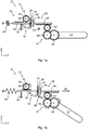
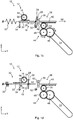
- Figs. 1a-1d schematically represent one example of an energy harvesting arrangement 10 comprising one example of a release mechanism 12.
- the energy harvesting arrangement 10 of this example further comprises a manual handle 14 and an electromagnetic generator 16.
- Figs. 1a-1d further indicates a Cartesian coordinate system for referencing purposes.
- the energy harvesting arrangement 10 may however be oriented arbitrarily in space.
- the release mechanism 12 comprises a drive device 18.
- the drive device 18 is arranged to drive the electromagnetic generator 16.
- the drive device 18 of this example comprises a drive member 20, a hinge 22 and a plate 24, here constituted by a steel plate.
- the plate 24 is rotationally coupled to the drive member 20 by means of the hinge 22.
- the drive device 18 further comprises a planar drive device surface 26, in this example constituted by a surface of the plate 24 (facing to the right in Fig. 1a ).
- the drive device 18 of this example further comprises a stop portion 28, here implemented as a projection on the drive member 20.
- the drive device 18 further comprises drive device teeth (not denoted), here implemented on the drive member 20.
- the release mechanism 12 further comprises a harvesting elastic element 30, here implemented as a coil spring.
- the harvesting elastic element 30 is connected to the drive device 18, in this example to the drive member 20, and to a stationary structure of the energy harvesting arrangement 10.
- the stationary structure is stationary in relation to the energy harvesting arrangement 10, but may be movable in space.
- the harvesting elastic element 30 is arranged to force the drive device 18 towards a starting position 32 according to Fig. 1a .
- the harvesting elastic element 30 is preloaded and holds the drive device 18 in the starting position 32.
- the energy harvesting arrangement 10 further comprises a stationary stop structure 34 (stationary with respect to the energy harvesting arrangement 10).
- the stop portion 28 of the drive device 18 abuts against the stop structure 34.
- the release mechanism 12 further comprises a magnet 36 and an input device 38.
- the input device 38 comprises the magnet 36 and an input member 40 to which the magnet 36 is rigidly connected.
- the input device 38 comprises a planar input device surface 42, here constituted by a surface of the magnet 36 (facing to the left in Fig. 1a ).
- the input device 38 of this example further comprises input device teeth (not denoted), here implemented on the input member 40.
- the energy harvesting arrangement 10 of the example in Fig. 1a further comprises a transmission 44 for transmitting a rotation of the handle 14 to a linear movement of the input device 38.
- the transmission 44 is in this example constituted by a gear train comprising a first gear wheel 46, a second gear wheel (not visible), a third gear wheel 48 and a fourth gear wheel 50.
- the handle 14 is rigidly connected to the first gear wheel 46, the first gear wheel 46 is in meshing engagement with the second gear wheel (behind the third gear wheel 48 in Fig. 1a ), the second gear wheel is rigidly connected to the third gear wheel 48, the third gear wheel 48 is in meshing engagement with the fourth gear wheel 50, and the fourth gear wheel 50 is in meshing engagement with the input device teeth of the input member 40.
- the transmission 44 between the handle 14 and the input device 38 is merely one of numerous possible transmissions for operatively coupling the handle 14 to the input device 38.
- the input device surface 42 mates with the drive device surface 26 and a mating interface between the magnet 36 and the plate 24 is established.
- the hinge 22 of the drive device 18 is centered with respect to the magnet 36 when the input device surface 42 mates with the drive device surface 26 mate.
- the magnet 36 is held in engagement with the plate 24 by means of an attractive magnetic force from the magnet 36 and acting on the plate 24.
- the mating interface is constituted by the contact area between the drive device surface 26 and the input device surface 42.
- the drive device surface 26 of the plate 24 has a larger height (larger dimension in the Z-direction) than the input device surface 42 of the magnet 36. Thereby, the plate 24 protrudes over the sides of the magnet 36.
- Each of the drive device surface 26 and the input device surface 42 may for example be quadrangular, such as rectangular or quadratic.
- the energy harvesting arrangement 10 of the example in Fig. 1a further comprises an engaging profile 52.
- the engaging profile 52 constitutes a stop member, here exemplified as a stop pin.
- the engaging profile 52 is stationary with respect to the energy harvesting arrangement 10.
- the engaging profile 52 does however not necessarily need to be stationary in space. For example, if the energy harvesting arrangement 10 is implemented in a door, also the engaging profile 52 may move together with the door.
- the electromagnetic generator 16 comprises a rotor, here implemented as a driven gear wheel 54, rotatable about a rotor rotational axis 56.
- the drive device teeth of the drive member 20 are arranged to engage the teeth of the driven gear wheel 54 and rotate the driven gear wheel 54 by means of a linear movement of the drive device 18. However, in Fig. 1a , the drive device teeth of the drive member 20 are disengaged from the gear wheel of the electromagnetic generator 16.
- the handle 14, the transmission 44 and the input device 38 may be said to be components of a primary side of the energy harvesting arrangement 10.
- the drive device 18 and the electromagnetic generator 16 may be said to be components of a secondary side of the energy harvesting arrangement 10.
- the drive device 18 Since the input device 38 engages the drive device 18 by means of a magnetic force, generated by the magnet 36 of the input device 38 and acting on the plate 24 of the drive device 18, the drive device 18 is displaced from the starting position 32 by the movement of the input device 38 along the harvesting path 58. As the drive device 18 is displaced from the starting position 32 along the harvesting path 58, mechanical energy is stored in the harvesting elastic element 30. That is, the harvesting elastic element 30 is tensioned more (or starts to be tensioned in case the harvesting elastic element 30 is not preloaded in the starting position 32).
- the drive device 18 also starts to engage the rotor of the electromagnetic generator 16, which thereby rotates slowly, as indicated in Fig. 1b . More specifically, the drive device teeth of the drive member 20 are brought in meshing engagement with the teeth of the driven gear wheel 54. At this stage, the energy harvesting is low. However, the energy harvested from this rotation of the driven gear wheel 54 may be used to wake up and perform an access control procedure of an access control device (described in Fig. 5 ), for example by means of BLE (Bluetooth Low Energy) communication.
- BLE Bluetooth Low Energy
- the holding force between the input device 38 and the drive device 18 is entirely magnetic.
- the engaging profile 52 starts to engage the drive device 18.
- This position of the drive device 18 constitutes an engaging position 60. More specifically, in the engaging position 60, a part of the plate 24 that protrudes outside the mating interface starts to contact the engaging profile 52.
- the engaging profile 52 is arranged offset with respect to the mating interface between the drive device surface 26 and the input device surface 42.
- the mating interface is also substantially perpendicular to the harvesting path 58.
- Fig. 1c shows how the input device 38 makes a slight further outbound movement along the energy harvesting path 58.
- the plate 24 since the plate 24 is stopped by the engaging profile 52, the plate 24 starts to incline or tilt (in the clockwise direction in Fig. ic). Thus, a relative inclination between the drive device surface 26 and the input device surface 42 occurs.
- the hinge 22 supports the relative inclination between the drive device surface 26 of the plate 24 and the input device surface 42 of the magnet 36.
- the engagement of the plate 24 by the engaging profile 52 and the hinge 22 provide a leverage.
- the force on the hinge 22 is relatively low.
- the magnet 36 is sensitive to air gaps. Thus, due to the relative inclination, the magnetic force is rapidly reduced and the release mechanism 12 is released, i.e. the harvesting elastic element 30 pulls the drive device 18 rapidly in a return movement along the harvesting path 58 to the starting position 32 as illustrated in Fig. 1d and a relatively high amount of energy is harvested by the electromagnetic generator 16. Since the drive device 18 does not engage the driven gear wheel 54 of the electromagnetic generator 16 in the starting position 32, the driven gear wheel 54 is allowed to spin until the energy from the release fades out.
- the gear ratio between the teeth of the drive member 20 and the driven gear wheel 54 may be optimized depending on the type of electromagnetic generator 16 used.
- a return spring in the handle 14 will return the handle 14 and the input device 38 to a starting position and a new energy harvesting cycle may be repeated.
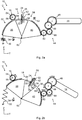
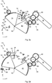
- Figs. 2a-2d schematically represent a further example of an energy harvesting arrangement 10 comprising further example of a release mechanism 12. Mainly differences from Figs. 1a-1d will be described.
- both the input device 38 and the drive device 18 are movable along a circular harvesting path 58.
- the drive device 18 comprises a drive member 20, here constituted by a sector gear, pivotally arranged about a rotational axis 62.
- the drive device 18 further comprises a drive device extension 64 protruding from the drive member 20.
- the plate 24 is rotationally supported relative to the drive device 18 by means of the hinge 22, which is provided at the end of the drive device extension 64.
- the input device 38 comprises an input member 40, here constituted by a sector shaped member, pivotally arranged about the rotational axis 62.
- the input device 38 further comprises an input device extension 66 protruding from the input member 40.
- the magnet 36 is rigidly connected to the end of the input device extension 66.
- the transmission 44 is also in this example constituted by a gear train, but comprises a further gear wheel 68 between the third gear wheel 48 and the fourth gear wheel 50.
- a side of the drive device 18 is held against the stop structure 34 by means of the tension force in the harvesting elastic element 30. Furthermore, the input device 38 engages the drive device 18 by means of a magnetic force, generated by the magnet 36 and acting between the drive device surface 26 and the input device surface 42.
- the plate 24 is brought into contact with the engaging profile 52. Further outbound movement of the input device 38 along the harvesting path 58 causes a relative inclination between the drive device surface 26 and the input device surface 42 due to the leverage provided by the hinge 22 and the engaging profile 52, as shown in Fig. 2c . As a consequence, the magnetic holding force is rapidly decreased causing a release of the release mechanism 12.
- the harvesting elastic element 30 now pulls the drive device 18 to make a return movement along the circular harvesting path 58 while energy of the movement is harvested by the electromagnetic generator 16, as shown in Fig. 2d .
- the drive device teeth on the drive member 20 move past the driven gear wheel 54 of the electromagnetic generator 16.
- the driven gear wheel 54 is thereby allowed to spin freely until the speed fades out.
- a return spring in the handle 14 will return the handle 14 and the input device 38 to a starting position and a new energy harvesting cycle may be repeated.
- FIG. 3 schematically represents a further example of an energy harvesting arrangement 10, a further example of a release mechanism 12 and a key 68. Mainly differences with respect to Figs. 1a-1d will be described.
- the input device 38 of the example in Fig. 3 comprises an input member 40 that can be actuated, directly or indirectly, by insertion of a key.
- the input member 40 may be constituted by a plate.
- the input device 38 of the release mechanism 12 in Fig. 3 has the same function as the input device 38 of the release mechanism 12 in Figs. 1a - id.
- Fig. 4 schematically represents a further example of an energy harvesting arrangement 10 comprising an access member hinge 72. Mainly differences with respect to Figs. 2a-2d will be described.
- the access member hinge 72 in Fig. 4 comprises a first hinge member 74 and a second hinge member 76.
- the second hinge member 74 of this example is rigidly connected to the first gear wheel 46.
- the input member 40 of the input device 38 in Fig. 4 is thereby indirectly connected to the second hinge member 76 of the access member hinge 72.
- the input device 38 of the release mechanism 12 in Fig. 4 has the same function as the input device 38 of the release mechanism 12 in Figs. 2a-2d .
- Fig. 5 schematically represents an environment in which embodiments presented herein can be applied. More specifically, Fig. 5 shows an electronic locking system 78 comprising the energy harvesting arrangement 10 according to the present disclosure and an electronic access control device 80. The access control device 80 is powerable by the electromagnetic generator 16 of the energy harvesting arrangement 10.
- Access to a physical space 82 is restricted by a movable access member 84 which is selectively unlockable.
- the movable access member 84 is positioned between the restricted physical space 82 and an accessible physical space 86.
- the accessible physical space 86 can be a restricted physical space in itself, but in relation to the access member 84, the accessible physical space 86 is accessible.
- the movable access member 84 can be a door, gate, hatch, cabinet door, drawer, window, etc.
- the electronic access control device 80 is arranged to unlock the access member 84.
- the access control device 80 is connected to a physical lock 88, which is controllable by the access control device 80 to be set in an unlocked state or locked state.
- the access control device 80 communicates with a portable key device 90 over a wireless interface 92 using a plurality of antennas 94a-b.
- the portable key device 90 is any suitable device portable by a user and which can be used for authentication over the wireless interface 92.
- the portable key device 90 is typically carried or worn by the user and may be implemented as a mobile phone, smartphone, key fob, wearable device, smart phone case, RFID (Radio Frequency Identification) card, etc.
- RFID Radio Frequency Identification
- two antennas 94a-b can be seen. However, only one antenna or more than two antennas may be provided in connection with the access control device 80.
- the authenticity and authority of the portable key device 90 can be checked in an access control procedure, e.g. using a challenge and response scheme, after which the access control device 80 grants or denies access.
- the access control device 80 sends an unlock signal to the lock 88, whereby the lock 88 is set in an unlocked state.
- this can e.g. imply a signal over a wire-based communication, e.g. using a serial interface (e.g. RS485, RS232), Universal Serial Bus (USB), Ethernet, or even a simple electric connection (e.g. to the lock 88), or alternatively using a wireless interface.
- a serial interface e.g. RS485, RS232), Universal Serial Bus (USB), Ethernet, or even a simple electric connection (e.g. to the lock 88), or alternatively using a wireless interface.
- the access member 84 When the lock 88 is in an unlocked state, the access member 84 can be opened and when the lock 88 is in a locked state, the access member 84 cannot be opened. In this way, access to a restricted physical space 82 can be controlled by the access control device 80.
Landscapes
- Physics & Mathematics (AREA)
- Electromagnetism (AREA)
- Lock And Its Accessories (AREA)
- Casings For Electric Apparatus (AREA)
- Transmission Devices (AREA)
- Telephone Set Structure (AREA)
Abstract
Description
- The present disclosure generally relates to a release mechanism. In particular, a release mechanism for an energy harvesting arrangement for an electronic locking system, an energy harvesting arrangement comprising the release mechanism, and an electronic locking system comprising the release mechanism or the energy harvesting arrangement, are provided.
- Various types of electronic locking systems are known, such as digital door locks (DDL). Instead of utilizing a purely mechanical lock, some locking systems include an electronic drive of a lock member (e.g. a lock bolt) to unlock, for example, a door to give access to the area behind the door.
- Furthermore, instead of utilizing a traditional key to unlock the door, various types of electronic communication methods for authorizing a person to access the area behind the door are known. For example, a Radio Frequency Identification (RFID) system may be used where a reader of the RFID system is installed in the door and a tag is carried by or attached to an object to be identified.
- In order to power an electronic locking system, so called "self-powered" electronic locking systems have been proposed, where electricity is generated by a mechanical actuation of a door handle and is used to power the electronic locking system. This concept is also known as energy harvesting. The use of kinetic energy harvesting can replace, or prolong the lifetime of, batteries in electronic locking systems.
-
US 2012111072 A1 discloses an electromechanical lock including a power transmission mechanism to receive mechanical power produced by a user of the lock; a generator to produce electric power from the mechanical power; an electronic circuit, powered by the electric power, coupleable with a key, to read data from the key, and to issue an open command provided that the data matches a predetermined criterion; an actuator, powered by the electric power, to receive the open command, and to set the lock in a mechanically openable state; and a threshold device to control the power transmission mechanism so that a mechanical tension rises until a predetermined force threshold is exceeded, whereupon the mechanical tension transforms to an action producing the mechanical power received by the power transmission mechanism. - Prior art energy harvesting arrangements for electronic locking systems are often complex and cause wear and tear of the components involved. Many prior art energy harvesting arrangements are also noisy.
- In
US 2012111072 A1 , the mechanical tension in the power transmission mechanism transforms to an action when exceeding a predetermined force threshold. This type of release requires a relatively high extra force in the release point. This may cause the handle movement to feel odd and/or low quality to the user. Many prior art energy harvesting arrangements also have an inconsistent energy level for release. - One object of the present disclosure is to provide a position controlled release mechanism for an energy harvesting arrangement for an electronic locking system.
- A further object of the present disclosure is to provide a release mechanism which requires a low amount of extra force to be released.
- A still further object of the present disclosure is to provide a release mechanism that is more silent.
- A still further object of the present disclosure is to provide a release mechanism that has a simple design, e.g. that requires fewer components.
- A still further object of the present disclosure is to provide a release mechanism that has high efficiency, such as low friction losses.
- A still further object of the present disclosure is to provide a release mechanism that is durable, e.g. with low sensitivity to wear and tear.
- A still further object of the present disclosure is to provide a release mechanism that is cheap.
- A still further object of the present disclosure is to provide a release mechanism that provides a reliable and consistent feedback in a handle or key over time.
- A still further object of the present disclosure is to provide a release mechanism that provides an improved user experience.
- A still further object of the present disclosure is to provide a release mechanism solving several or all of the foregoing objects.
- A still further object of the present disclosure is to provide an energy harvesting system comprising a release mechanism, which energy harvesting system solves one, several or all of the foregoing objects.
- A still further object of the present disclosure is to provide an electronic locking system comprising a release mechanism, which electronic locking system solves one, several or all of the foregoing objects.
- According to one aspect, there is provided a release mechanism for an energy harvesting arrangement for an electronic locking system, the release mechanism comprising a drive device for driving an electromagnetic generator, the drive device comprising a substantially planar, or planar, drive device surface; a harvesting elastic element arranged to force the drive device towards a starting position, and arranged to store mechanical energy from displacement of the drive device from the starting position along a harvesting path; at least one magnet; an input device, the input device being movable along the harvesting path, and comprising a substantially planar, or planar, input device surface arranged to mate with the drive device surface to establish a mating interface; and an engaging profile arranged offset with respect to the mating interface; wherein the input device is arranged to engage the drive device by means of a magnetic force, generated by the magnet and acting between the drive device surface and the input device surface, such that the drive device can be displaced from the starting position by movement of the input device along the harvesting path; and wherein the engaging profile is arranged to engage the drive device at an engaging position of the drive device, such that further movement of the input device along the harvesting path causes a relative inclination between the drive device surface and the input device surface.
- By relatively inclining or tilting the drive device surface and the input device surface, an inclined load is established at the mating interface. The air gap that arises between the drive device surface and the input device surface causes the magnetic force to rapidly decrease as the input device is moved further along the harvesting path. This collapse of the magnetic force causes the drive device to be released.
- Since further movement of the input device along the harvesting path when the drive device is engaged by the engaging profile causes a relative inclination between the drive device surface and the input device surface, the amount of extra force required for the release is substantially reduced. The amount of friction to be overcome for the release is also substantially lower than in prior art solutions. As a consequence, the efficiency of the release mechanism is increased, the wear and tear of the release mechanism is reduced, and the user experience is improved.
- Furthermore, the rapid collapse of the magnetic force when the drive device surface and the input device surface start to tilt relative to each other results in a release of the drive device at a defined position of the input device along the harvesting path. In other words, the release is position controlled in contrast to, for example, the power transmission mechanism in
US 2012111072 A1 which is based on a threshold force. Due to this position controlled release, variations of the strength of the magnetic field due to, for example, temperature or production parameter spread will not affect the function of the release mechanism. - Furthermore, the position-based release of the release mechanism according to the present disclosure is more consistent over time in comparison with prior art force-based release mechanisms. The magnet-based release mechanism according to the present disclosure is also more silent and less exposed to wear and tear.
- Furthermore, since the drive device is always released when the input device moves further after engagement between the drive device and the engaging profile, the release mechanism includes an intrinsic damage protection, i.e. a limitation of the maximum force that can be applied on the drive device.
- Throughout the present disclosure, the input device may be arranged to receive power produced by a user, such as a user of an electronic locking system comprising the energy harvesting system which in turn comprises the release mechanism.
- The drive device may be arranged to drive a rotor of the electromagnetic generator, either directly, or indirectly. The rotor may be constituted by a driven wheel, such as a driven gear wheel or a driven friction wheel.
- The harvesting elastic element may store mechanical energy from displacement of the drive device from the starting position along the harvesting path either by compression or by expansion. The harvesting elastic element may be preloaded when the drive device is in the starting position.
- The harvesting elastic element may for example be constituted by a spring, such as a coil spring. Alternative harvesting elastic elements are possible, including for example a piece of elastic material. The harvesting elastic element may alternatively be referred to as an elastic element.
- The magnet may be a permanent magnet. The magnet may comprise, or be constituted by, Neodynium, a Neodymium alloy such as a Neodymium-Iron-Boron (NdFeB), or other material having a relatively high intrinsic coercivity. The release mechanism according to the present disclosure may comprise one or several magnets.
- The input device may be said to be arranged on a primary side of the release mechanism and the drive device may be said to be arranged on a secondary side of the release mechanism. Thus, throughout the present disclosure, the input device may alternatively be referred to as a primary device and/or the drive device may alternatively be referred to as a secondary device.
- The release mechanism may comprise a hinge arranged to support the relative inclination between the drive device surface and the input device surface. A leverage can thereby be obtained by means of the hinge and the engaging profile. The leverage makes it possible to dynamically control the release mechanism.
- The hinge may be provided in the drive device and support inclination of the drive device surface. Alternatively, the hinge may be provided in the input device and support inclination of the input device surface. Alternatives to a hinge are possible, including for example the provision of one or more elastic elements in the drive device and/or in the input device for enabling a relative inclination between the drive device surface and the input device surface.
- The hinge may be substantially centered, or centered, with respect to the magnet when the planar input device surface and the drive device surface mate.
- The release mechanism may comprise a plate, wherein the plate comprises the drive device surface or the input device surface. The plate may comprise one or more materials responsive to magnetic fields. The plate may for example be a steel plate, or may comprise steel.
- According to one variant, the drive device comprises the plate, optionally supported by means of a hinge. In this case, the input device may comprise the magnet. According to an alternative variant, the input device comprises the plate, optionally supported by means of a hinge. In this case the drive device may comprise the magnet.
- The magnetic force may be 10% to 30% larger than the force from the harvesting elastic element when the drive device is in the engaging position. Thereby, it can be ensured that the drive device is not released immediately when coming in contact with the engaging profile in the engaging position.
- The input device may be arranged to engage the drive device by means of an attractive magnetic force. It is however alternatively possible to base the release mechanism according to the present disclosure on a repelling magnetic force, i.e. such that the input device is arranged to engage the drive device by means of a repelling magnetic force.
- The mating interface may be substantially perpendicular, or perpendicular, to the harvesting path. The mating interface may be constituted by the area of contact between the drive device surface and the input device surface.
- The harvesting path may be substantially linear, or linear. Alternatively, the harvesting path may be substantially circular, or circular.
- According to a further aspect, there is provided an energy harvesting arrangement comprising a release mechanism according to the present disclosure. The energy harvesting arrangement may comprise the electromagnetic generator drivable by the drive device. The electromagnetic generator may be arranged to produce electric power from the mechanical power input by a user to the input device. A standard electromagnetic generator may be used in the energy harvesting arrangement. The drive device may drive the electromagnetic generator directly or indirectly. The energy harvesting arrangement may comprise a transmission, such as a gear train, between the drive device and the electromagnetic generator. This may be suitable for smaller electromagnetic generators.
- The drive device may be arranged to not engage the rotor of the electromagnetic generator when the drive device adopts the starting position and such that the drive device starts to engage the rotor when the drive device is displaced along the harvesting path from the starting position. Thereby, the electromagnetic generator does not need to comprise a freewheel. Furthermore, the rotor of the electromagnetic generator is allowed to spin freely after release and when the drive device has returned to the starting position, e.g. functionally "beyond" the rotor. In case the drive device and the rotor comprise teeth, the rotor and/or the drive device may be resiliently supported to assist in initiation of meshing of the teeth.
- The energy harvesting arrangement may be used in various types of electronic locking systems, e.g. various door opening solutions. The energy harvesting arrangement may comprise a transmission, such as a gear transmission, to transmit a manual movement (e.g. handle movement, door movement, or key movement) to a movement of the input device along the harvesting path.
- The energy harvesting arrangement may further comprise a handle operatively coupled to the input device. Thereby, manual actuation of the handle can be used to drive the input device of the release mechanism. In this case, the energy harvesting arrangement may comprise a transmission, e.g. a gear train, to transmit a rotation of the handle to a movement of the input device. The gear train may be arranged to transmit a rotation of the handle, e.g. of 40° to 45°, to a movement (either linear or rotational) of the input device beyond the releasing position.
- Alternatively, the energy harvesting arrangement may further comprise an access member hinge operatively coupled to the input device. The access member hinge may be arranged to support an access member relative to a frame. Thereby, an opening or closing movement of the access member can be used to drive the input device of the release mechanism.
- Alternatively, the input device may be arranged to be actuated by means of a key. For example, the input device may be pushed to move along the harvesting path by insertion of the key. According to one variant, the input device is arranged to be directly contacted by the key.
- Further non-limiting application examples of the energy harvesting arrangements according to the present disclosure include door closers and windows.
- According to a further aspect, there is provided an electronic locking system comprising a release mechanism according to the present disclosure, or an energy harvesting arrangement according to the present disclosure.
- Further details, advantages and aspects of the present disclosure will become apparent from the following embodiments taken in conjunction with the drawings, wherein:
- Figs. 1a-1d:
- schematically represent one example of an energy harvesting system comprising one example of a release mechanism;
- Figs. 2a-2d:
- schematically represent a further example of an energy harvesting system comprising further example of a release mechanism;
- Fig. 3:
- schematically represents a further example of an energy harvesting system, a further example of a release mechanism and a key;
- Fig. 4:
- schematically represents a further example of an energy harvesting system comprising an access member hinge; and
- Fig. 5:
- schematically represents an environment in which embodiments presented herein can be applied.
- In the following, a release mechanism for an energy harvesting arrangement for an electronic locking system, an energy harvesting arrangement comprising the release mechanism, and an electronic locking system comprising the release mechanism or the energy harvesting arrangement, will be described. The same reference numerals will be used to denote the same or similar structural features.
-
Figs. 1a-1d schematically represent one example of anenergy harvesting arrangement 10 comprising one example of arelease mechanism 12. Theenergy harvesting arrangement 10 of this example further comprises amanual handle 14 and anelectromagnetic generator 16.Figs. 1a-1d further indicates a Cartesian coordinate system for referencing purposes. Theenergy harvesting arrangement 10 may however be oriented arbitrarily in space. - With reference to
Fig. 1a , therelease mechanism 12 comprises adrive device 18. Thedrive device 18 is arranged to drive theelectromagnetic generator 16. - The
drive device 18 of this example comprises adrive member 20, ahinge 22 and aplate 24, here constituted by a steel plate. Theplate 24 is rotationally coupled to thedrive member 20 by means of thehinge 22. Thedrive device 18 further comprises a planardrive device surface 26, in this example constituted by a surface of the plate 24 (facing to the right inFig. 1a ). - The
drive device 18 of this example further comprises astop portion 28, here implemented as a projection on thedrive member 20. Thedrive device 18 further comprises drive device teeth (not denoted), here implemented on thedrive member 20. - The
release mechanism 12 further comprises a harvestingelastic element 30, here implemented as a coil spring. The harvestingelastic element 30 is connected to thedrive device 18, in this example to thedrive member 20, and to a stationary structure of theenergy harvesting arrangement 10. The stationary structure is stationary in relation to theenergy harvesting arrangement 10, but may be movable in space. - The harvesting
elastic element 30 is arranged to force thedrive device 18 towards a startingposition 32 according toFig. 1a . In the startingposition 32, the harvestingelastic element 30 is preloaded and holds thedrive device 18 in the startingposition 32. Theenergy harvesting arrangement 10 further comprises a stationary stop structure 34 (stationary with respect to the energy harvesting arrangement 10). In the startingposition 32 of thedrive device 18 according toFig. 1a , thestop portion 28 of thedrive device 18 abuts against thestop structure 34. - The
release mechanism 12 further comprises amagnet 36 and aninput device 38. In this example, theinput device 38 comprises themagnet 36 and aninput member 40 to which themagnet 36 is rigidly connected. Theinput device 38 comprises a planarinput device surface 42, here constituted by a surface of the magnet 36 (facing to the left inFig. 1a ). Theinput device 38 of this example further comprises input device teeth (not denoted), here implemented on theinput member 40. - The
energy harvesting arrangement 10 of the example inFig. 1a further comprises atransmission 44 for transmitting a rotation of thehandle 14 to a linear movement of theinput device 38. Thetransmission 44 is in this example constituted by a gear train comprising afirst gear wheel 46, a second gear wheel (not visible), athird gear wheel 48 and afourth gear wheel 50. Thehandle 14 is rigidly connected to thefirst gear wheel 46, thefirst gear wheel 46 is in meshing engagement with the second gear wheel (behind thethird gear wheel 48 inFig. 1a ), the second gear wheel is rigidly connected to thethird gear wheel 48, thethird gear wheel 48 is in meshing engagement with thefourth gear wheel 50, and thefourth gear wheel 50 is in meshing engagement with the input device teeth of theinput member 40. Thetransmission 44 between thehandle 14 and theinput device 38 is merely one of numerous possible transmissions for operatively coupling thehandle 14 to theinput device 38. - In
Fig. 1a , theinput device surface 42 mates with thedrive device surface 26 and a mating interface between themagnet 36 and theplate 24 is established. Thehinge 22 of thedrive device 18 is centered with respect to themagnet 36 when theinput device surface 42 mates with thedrive device surface 26 mate. Themagnet 36 is held in engagement with theplate 24 by means of an attractive magnetic force from themagnet 36 and acting on theplate 24. The mating interface is constituted by the contact area between thedrive device surface 26 and theinput device surface 42. - As can be gathered from
Fig. 1a , thedrive device surface 26 of theplate 24 has a larger height (larger dimension in the Z-direction) than theinput device surface 42 of themagnet 36. Thereby, theplate 24 protrudes over the sides of themagnet 36. Each of thedrive device surface 26 and theinput device surface 42 may for example be quadrangular, such as rectangular or quadratic. - The
energy harvesting arrangement 10 of the example inFig. 1a further comprises an engagingprofile 52. The engagingprofile 52 constitutes a stop member, here exemplified as a stop pin. The engagingprofile 52 is stationary with respect to theenergy harvesting arrangement 10. The engagingprofile 52 does however not necessarily need to be stationary in space. For example, if theenergy harvesting arrangement 10 is implemented in a door, also the engagingprofile 52 may move together with the door. - The
electromagnetic generator 16 comprises a rotor, here implemented as a drivengear wheel 54, rotatable about a rotorrotational axis 56. The drive device teeth of thedrive member 20 are arranged to engage the teeth of the drivengear wheel 54 and rotate the drivengear wheel 54 by means of a linear movement of thedrive device 18. However, inFig. 1a , the drive device teeth of thedrive member 20 are disengaged from the gear wheel of theelectromagnetic generator 16. - In
Fig. 1a , thehandle 14, thetransmission 44 and theinput device 38 may be said to be components of a primary side of theenergy harvesting arrangement 10. Thedrive device 18 and theelectromagnetic generator 16 may be said to be components of a secondary side of theenergy harvesting arrangement 10. - With reference to
Figs. 1a-1d , a method of operating theenergy harvesting arrangement 10 will now be described. When thehandle 14 is rotated in a first direction by a user as indicated inFig. 1b , an external force is applied on the input device 38 (due to the transmission 44) and theinput device 38 starts to move linearly in an outbound direction along aharvesting path 58. - Since the
input device 38 engages thedrive device 18 by means of a magnetic force, generated by themagnet 36 of theinput device 38 and acting on theplate 24 of thedrive device 18, thedrive device 18 is displaced from the startingposition 32 by the movement of theinput device 38 along theharvesting path 58. As thedrive device 18 is displaced from the startingposition 32 along theharvesting path 58, mechanical energy is stored in the harvestingelastic element 30. That is, the harvestingelastic element 30 is tensioned more (or starts to be tensioned in case the harvestingelastic element 30 is not preloaded in the starting position 32). - During this outbound movement of the
drive device 18, thedrive device 18 also starts to engage the rotor of theelectromagnetic generator 16, which thereby rotates slowly, as indicated inFig. 1b . More specifically, the drive device teeth of thedrive member 20 are brought in meshing engagement with the teeth of the drivengear wheel 54. At this stage, the energy harvesting is low. However, the energy harvested from this rotation of the drivengear wheel 54 may be used to wake up and perform an access control procedure of an access control device (described inFig. 5 ), for example by means of BLE (Bluetooth Low Energy) communication. - During the outbound movement of the
input device 38 and thedrive device 18 along theharvesting path 58, the holding force between theinput device 38 and thedrive device 18 is entirely magnetic. In the position of thedrive device 18 inFig. 1b , the engagingprofile 52 starts to engage thedrive device 18. This position of thedrive device 18 constitutes anengaging position 60. More specifically, in theengaging position 60, a part of theplate 24 that protrudes outside the mating interface starts to contact the engagingprofile 52. Thus, the engagingprofile 52 is arranged offset with respect to the mating interface between thedrive device surface 26 and theinput device surface 42. As can be seen inFig. 1b , the mating interface is also substantially perpendicular to theharvesting path 58. When thedrive device 18 adopts theengaging position 60 according toFig. 1b , the holding force of themagnet 36 is approximately 10% to 30% larger than the force in the harvestingelastic element 30. -
Fig. 1c shows how theinput device 38 makes a slight further outbound movement along theenergy harvesting path 58. However, since theplate 24 is stopped by the engagingprofile 52, theplate 24 starts to incline or tilt (in the clockwise direction in Fig. ic). Thus, a relative inclination between thedrive device surface 26 and theinput device surface 42 occurs. Thehinge 22 supports the relative inclination between thedrive device surface 26 of theplate 24 and theinput device surface 42 of themagnet 36. In this example, the engagement of theplate 24 by the engagingprofile 52 and thehinge 22 provide a leverage. The force on thehinge 22 is relatively low. - The
magnet 36 is sensitive to air gaps. Thus, due to the relative inclination, the magnetic force is rapidly reduced and therelease mechanism 12 is released, i.e. the harvestingelastic element 30 pulls thedrive device 18 rapidly in a return movement along theharvesting path 58 to the startingposition 32 as illustrated inFig. 1d and a relatively high amount of energy is harvested by theelectromagnetic generator 16. Since thedrive device 18 does not engage the drivengear wheel 54 of theelectromagnetic generator 16 in the startingposition 32, the drivengear wheel 54 is allowed to spin until the energy from the release fades out. The gear ratio between the teeth of thedrive member 20 and the drivengear wheel 54 may be optimized depending on the type ofelectromagnetic generator 16 used. - Due to the release of the
release mechanism 12 by means of a relative inclination between thedrive device surface 26 and theinput device surface 42, the force required for release is reduced. The release of thedrive device 18 due to a rapidly decreasing magnetic force in this way is also relatively silent. - After release, a return spring in the
handle 14 will return thehandle 14 and theinput device 38 to a starting position and a new energy harvesting cycle may be repeated. -
Figs. 2a-2d schematically represent a further example of anenergy harvesting arrangement 10 comprising further example of arelease mechanism 12. Mainly differences fromFigs. 1a-1d will be described. - In the example in
Figs. 2a-2d , both theinput device 38 and thedrive device 18 are movable along acircular harvesting path 58. With reference toFig. 2a , thedrive device 18 comprises adrive member 20, here constituted by a sector gear, pivotally arranged about arotational axis 62. Thedrive device 18 further comprises adrive device extension 64 protruding from thedrive member 20. Theplate 24 is rotationally supported relative to thedrive device 18 by means of thehinge 22, which is provided at the end of thedrive device extension 64. - The
input device 38 comprises aninput member 40, here constituted by a sector shaped member, pivotally arranged about therotational axis 62. Theinput device 38 further comprises aninput device extension 66 protruding from theinput member 40. Themagnet 36 is rigidly connected to the end of theinput device extension 66. - The
transmission 44 is also in this example constituted by a gear train, but comprises afurther gear wheel 68 between thethird gear wheel 48 and thefourth gear wheel 50. - In the starting
position 32 of thedrive device 18 inFig. 2a , a side of thedrive device 18 is held against thestop structure 34 by means of the tension force in the harvestingelastic element 30. Furthermore, theinput device 38 engages thedrive device 18 by means of a magnetic force, generated by themagnet 36 and acting between thedrive device surface 26 and theinput device surface 42. - By manually rotating the
handle 14, as shown inFig. 2b , theinput device 38 and thedrive device 18, which is held by the magnetic force, rotate in an outbound direction along thecircular harvesting path 58. Energy from the outbound displacement of thedrive device 18 from the startingposition 32 is stored by the harvestingelastic element 30. - At the engaging
position 60 of thedrive device 18 ofFig. 2b , theplate 24 is brought into contact with the engagingprofile 52. Further outbound movement of theinput device 38 along theharvesting path 58 causes a relative inclination between thedrive device surface 26 and theinput device surface 42 due to the leverage provided by thehinge 22 and the engagingprofile 52, as shown inFig. 2c . As a consequence, the magnetic holding force is rapidly decreased causing a release of therelease mechanism 12. The harvestingelastic element 30 now pulls thedrive device 18 to make a return movement along thecircular harvesting path 58 while energy of the movement is harvested by theelectromagnetic generator 16, as shown inFig. 2d . The drive device teeth on thedrive member 20 move past the drivengear wheel 54 of theelectromagnetic generator 16. The drivengear wheel 54 is thereby allowed to spin freely until the speed fades out. - After release, a return spring in the
handle 14 will return thehandle 14 and theinput device 38 to a starting position and a new energy harvesting cycle may be repeated. -
Fig. 3 schematically represents a further example of anenergy harvesting arrangement 10, a further example of arelease mechanism 12 and a key 68. Mainly differences with respect toFigs. 1a-1d will be described. - Instead of being coupled to a
handle 14 by means of atransmission 44 according toFigs. 1a-1d , theinput device 38 of the example inFig. 3 comprises aninput member 40 that can be actuated, directly or indirectly, by insertion of a key. Theinput member 40 may be constituted by a plate. Otherwise, theinput device 38 of therelease mechanism 12 inFig. 3 has the same function as theinput device 38 of therelease mechanism 12 inFigs. 1a - id. -
Fig. 4 schematically represents a further example of anenergy harvesting arrangement 10 comprising anaccess member hinge 72. Mainly differences with respect toFigs. 2a-2d will be described. - The
access member hinge 72 inFig. 4 comprises a first hinge member 74 and asecond hinge member 76. The second hinge member 74 of this example is rigidly connected to thefirst gear wheel 46. Theinput member 40 of theinput device 38 inFig. 4 is thereby indirectly connected to thesecond hinge member 76 of theaccess member hinge 72. Thus, by opening an access member supported by theaccess member hinge 72, theinput device 38 is actuated. Theinput device 38 of therelease mechanism 12 inFig. 4 has the same function as theinput device 38 of therelease mechanism 12 inFigs. 2a-2d . -
Fig. 5 schematically represents an environment in which embodiments presented herein can be applied. More specifically,Fig. 5 shows anelectronic locking system 78 comprising theenergy harvesting arrangement 10 according to the present disclosure and an electronicaccess control device 80. Theaccess control device 80 is powerable by theelectromagnetic generator 16 of theenergy harvesting arrangement 10. - Access to a
physical space 82 is restricted by amovable access member 84 which is selectively unlockable. Themovable access member 84 is positioned between the restrictedphysical space 82 and an accessiblephysical space 86. Note that the accessiblephysical space 86 can be a restricted physical space in itself, but in relation to theaccess member 84, the accessiblephysical space 86 is accessible. Themovable access member 84 can be a door, gate, hatch, cabinet door, drawer, window, etc. - The electronic
access control device 80 is arranged to unlock theaccess member 84. Theaccess control device 80 is connected to aphysical lock 88, which is controllable by theaccess control device 80 to be set in an unlocked state or locked state. - The
access control device 80 communicates with a portablekey device 90 over awireless interface 92 using a plurality ofantennas 94a-b. The portablekey device 90 is any suitable device portable by a user and which can be used for authentication over thewireless interface 92. The portablekey device 90 is typically carried or worn by the user and may be implemented as a mobile phone, smartphone, key fob, wearable device, smart phone case, RFID (Radio Frequency Identification) card, etc. InFig. 5 , twoantennas 94a-b can be seen. However, only one antenna or more than two antennas may be provided in connection with theaccess control device 80. Using wireless communication, the authenticity and authority of the portablekey device 90 can be checked in an access control procedure, e.g. using a challenge and response scheme, after which theaccess control device 80 grants or denies access. - When the access control procedure results in granted access, the
access control device 80 sends an unlock signal to thelock 88, whereby thelock 88 is set in an unlocked state. In this embodiment, this can e.g. imply a signal over a wire-based communication, e.g. using a serial interface (e.g. RS485, RS232), Universal Serial Bus (USB), Ethernet, or even a simple electric connection (e.g. to the lock 88), or alternatively using a wireless interface. - When the
lock 88 is in an unlocked state, theaccess member 84 can be opened and when thelock 88 is in a locked state, theaccess member 84 cannot be opened. In this way, access to a restrictedphysical space 82 can be controlled by theaccess control device 80. - While the present disclosure has been described with reference to exemplary embodiments, it will be appreciated that the present invention is not limited to what has been described above. For example, it will be appreciated that the dimensions of the parts may be varied as needed.
Claims (15)
- Release mechanism (12) for an energy harvesting arrangement (10) for an electronic locking system (78), the release mechanism (12) comprising:- a drive device (18) for driving an electromagnetic generator (16), the drive device (18) comprising a substantially planar drive device surface (26);- a harvesting elastic element (30) arranged to force the drive device (18) towards a starting position (32), and arranged to store mechanical energy from displacement of the drive device (18) from the starting position (32) along a harvesting path (58);- at least one magnet (36);- an input device (38), the input device (38) being movable along the harvesting path (58), and comprising a substantially planar input device surface (42) arranged to mate with the drive device surface (26) to establish a mating interface; and- an engaging profile (52) arranged offset with respect to the mating interface;wherein the input device (38) is arranged to engage the drive device (18) by means of a magnetic force, generated by the magnet (36) and acting between the drive device surface (26) and the input device surface (42), such that the drive device (18) can be displaced from the starting position (32) by movement of the input device (38) along the harvesting path (58); and
wherein the engaging profile (52) is arranged to engage the drive device (18) at an engaging position (60) of the drive device (18), such that further movement of the input device (38) along the harvesting path (58) causes a relative inclination between the drive device surface (26) and the input device surface (42). - The release mechanism (12) according to claim 1, wherein the release mechanism (12) comprises a hinge (22) arranged to support the relative inclination between the drive device surface (26) and the input device surface (42).
- The release mechanism (12) according to claim 2, wherein the hinge (22) is substantially centered with respect to the magnet (36) when the planar input device surface (42) and the drive device surface (26) mate.
- The release mechanism (12) according to any of the preceding claims, wherein the release mechanism (12) comprises a plate (24), wherein the plate (24) comprises the drive device surface (26) or the input device surface (42).
- The release mechanism (12) according to claim 4, wherein the drive device (18) comprises the plate (24).
- The release mechanism (12) according to any of the preceding claims, wherein the input device (38) comprises the magnet (36).
- The release mechanism (12) according to any of the preceding claims, wherein the magnetic force is 10% to 30% larger than the force from the harvesting elastic element (30) when the drive device (18) is in the engaging position (60).
- The release mechanism (12) according to any of the preceding claims, wherein the input device (38) is arranged to engage the drive device (18) by means of an attractive magnetic force.
- The release mechanism (12) according to any of the preceding claims, wherein the mating interface is substantially perpendicular to the harvesting path (58).
- The release mechanism (12) according to any of the preceding claims, wherein the harvesting path (58) is substantially linear.
- The release mechanism (12) according to any of claims 1 to 9, wherein the harvesting path (58) is substantially circular.
- Energy harvesting arrangement (10) comprising a release mechanism (12) according to any of the preceding claims.
- The energy harvesting arrangement (10) according to claim 12, further comprises a handle (14) operatively coupled to the input device (38) or an access member hinge (72) operatively coupled to the input device (38).
- The energy harvesting arrangement (10) according to claim 12, wherein the input device (38) is arranged to be actuated by means of a key (68).
- Electronic locking system (78) comprising a release mechanism (12) according to any of claims 1 to 12, or an energy harvesting arrangement (10) according to any of claims 12 to 14.
Priority Applications (5)
| Application Number | Priority Date | Filing Date | Title |
|---|---|---|---|
| EP18163507.9A EP3543442B1 (en) | 2018-03-23 | 2018-03-23 | Release mechanism, energy harvesting arrangement and electronic locking system |
| US16/963,617 US11939794B2 (en) | 2018-03-23 | 2019-03-20 | Release mechanism, energy harvesting arrangement and electronic locking system |
| KR1020207026880A KR102613332B1 (en) | 2018-03-23 | 2019-03-20 | Release mechanism, energy harvesting device and electronic locking system |
| PCT/EP2019/056912 WO2019180059A1 (en) | 2018-03-23 | 2019-03-20 | Release mechanism, energy harvesting arrangement and electronic locking system |
| CN201980020901.8A CN111886390B (en) | 2018-03-23 | 2019-03-20 | Release mechanism, energy harvesting device, and electronic locking system |
Applications Claiming Priority (1)
| Application Number | Priority Date | Filing Date | Title |
|---|---|---|---|
| EP18163507.9A EP3543442B1 (en) | 2018-03-23 | 2018-03-23 | Release mechanism, energy harvesting arrangement and electronic locking system |
Publications (2)
| Publication Number | Publication Date |
|---|---|
| EP3543442A1 true EP3543442A1 (en) | 2019-09-25 |
| EP3543442B1 EP3543442B1 (en) | 2020-07-29 |
Family
ID=61763843
Family Applications (1)
| Application Number | Title | Priority Date | Filing Date |
|---|---|---|---|
| EP18163507.9A Active EP3543442B1 (en) | 2018-03-23 | 2018-03-23 | Release mechanism, energy harvesting arrangement and electronic locking system |
Country Status (5)
| Country | Link |
|---|---|
| US (1) | US11939794B2 (en) |
| EP (1) | EP3543442B1 (en) |
| KR (1) | KR102613332B1 (en) |
| CN (1) | CN111886390B (en) |
| WO (1) | WO2019180059A1 (en) |
Cited By (1)
| Publication number | Priority date | Publication date | Assignee | Title |
|---|---|---|---|---|
| US11939794B2 (en) | 2018-03-23 | 2024-03-26 | Assa Abloy Ab | Release mechanism, energy harvesting arrangement and electronic locking system |
Families Citing this family (4)
| Publication number | Priority date | Publication date | Assignee | Title |
|---|---|---|---|---|
| US11639617B1 (en) | 2019-04-03 | 2023-05-02 | The Chamberlain Group Llc | Access control system and method |
| SE546648C2 (en) * | 2021-07-05 | 2025-01-07 | Assa Abloy Ab | An arrangement for closing an access member, and an access member system |
| SE545243C2 (en) * | 2021-10-22 | 2023-06-07 | Assa Abloy Ab | Energy harvesting arrangement, access member device and access member system |
| EP4353928A3 (en) * | 2022-09-23 | 2024-06-12 | Schulte-Schlagbaum Aktiengesellschaft | Lock with energy converter |
Citations (3)
| Publication number | Priority date | Publication date | Assignee | Title |
|---|---|---|---|---|
| US3733861A (en) * | 1972-01-19 | 1973-05-22 | Recognition Devices | Electronic recognition door lock |
| US20120111072A1 (en) * | 2005-12-16 | 2012-05-10 | Mika Pukari | Electromechanical lock and its operation method |
| WO2013085057A1 (en) * | 2011-12-09 | 2013-06-13 | 株式会社岡村製作所 | Power generator |
Family Cites Families (5)
| Publication number | Priority date | Publication date | Assignee | Title |
|---|---|---|---|---|
| GB2347800B (en) | 1999-03-10 | 2003-05-28 | Ericsson Telefon Ab L M | Battery charger |
| CN2608633Y (en) | 2003-02-17 | 2004-03-31 | 曾艺 | Electron lock and bullet lock combined antitheft door lock device |
| CN202079544U (en) | 2011-01-19 | 2011-12-21 | 李建龙 | Self-charging lighting screwdriver |
| JP2016169526A (en) | 2015-03-12 | 2016-09-23 | パナソニック デバイスSunx竜野株式会社 | Charger for door |
| EP3543442B1 (en) | 2018-03-23 | 2020-07-29 | Assa Abloy AB | Release mechanism, energy harvesting arrangement and electronic locking system |
-
2018
- 2018-03-23 EP EP18163507.9A patent/EP3543442B1/en active Active
-
2019
- 2019-03-20 CN CN201980020901.8A patent/CN111886390B/en active Active
- 2019-03-20 US US16/963,617 patent/US11939794B2/en active Active
- 2019-03-20 KR KR1020207026880A patent/KR102613332B1/en active Active
- 2019-03-20 WO PCT/EP2019/056912 patent/WO2019180059A1/en not_active Ceased
Patent Citations (3)
| Publication number | Priority date | Publication date | Assignee | Title |
|---|---|---|---|---|
| US3733861A (en) * | 1972-01-19 | 1973-05-22 | Recognition Devices | Electronic recognition door lock |
| US20120111072A1 (en) * | 2005-12-16 | 2012-05-10 | Mika Pukari | Electromechanical lock and its operation method |
| WO2013085057A1 (en) * | 2011-12-09 | 2013-06-13 | 株式会社岡村製作所 | Power generator |
Cited By (1)
| Publication number | Priority date | Publication date | Assignee | Title |
|---|---|---|---|---|
| US11939794B2 (en) | 2018-03-23 | 2024-03-26 | Assa Abloy Ab | Release mechanism, energy harvesting arrangement and electronic locking system |
Also Published As
| Publication number | Publication date |
|---|---|
| EP3543442B1 (en) | 2020-07-29 |
| CN111886390B (en) | 2021-10-15 |
| KR20200133342A (en) | 2020-11-27 |
| US20210062545A1 (en) | 2021-03-04 |
| CN111886390A (en) | 2020-11-03 |
| WO2019180059A1 (en) | 2019-09-26 |
| US11939794B2 (en) | 2024-03-26 |
| KR102613332B1 (en) | 2023-12-14 |
Similar Documents
| Publication | Publication Date | Title |
|---|---|---|
| US11939794B2 (en) | Release mechanism, energy harvesting arrangement and electronic locking system | |
| US20230203843A1 (en) | Electromagnetic actuator | |
| US11965359B2 (en) | Energy harvesting arrangement and electronic locking system | |
| KR101954870B1 (en) | Electromechanical locks utilizing magnetic tension | |
| US10890014B2 (en) | Electromagnetic actuator | |
| CN111279040B (en) | Electromechanical lock using magnetic field force | |
| EP4245952B1 (en) | Lock device for an electronic locking system, electronic locking system and method | |
| US11861958B2 (en) | Mechanisms, assemblies and electronic locking system | |
| HUP0001475A2 (en) | Lock mechanism | |
| CN101360881A (en) | Electromechanical lock and its operation method | |
| EP4204647B1 (en) | Arrangement for lock device, lock device comprising arrangement, and method | |
| CN221073822U (en) | Electronic knob lock | |
| HK40035076B (en) | Electromagnetic actuator | |
| HK40035076A (en) | Electromagnetic actuator | |
| HK40035075A (en) | Digital lock | |
| HK40035075B (en) | Digital lock |
Legal Events
| Date | Code | Title | Description |
|---|---|---|---|
| PUAI | Public reference made under article 153(3) epc to a published international application that has entered the european phase |
Free format text: ORIGINAL CODE: 0009012 |
|
| STAA | Information on the status of an ep patent application or granted ep patent |
Free format text: STATUS: THE APPLICATION HAS BEEN PUBLISHED |
|
| AK | Designated contracting states |
Kind code of ref document: A1 Designated state(s): AL AT BE BG CH CY CZ DE DK EE ES FI FR GB GR HR HU IE IS IT LI LT LU LV MC MK MT NL NO PL PT RO RS SE SI SK SM TR |
|
| AX | Request for extension of the european patent |
Extension state: BA ME |
|
| STAA | Information on the status of an ep patent application or granted ep patent |
Free format text: STATUS: REQUEST FOR EXAMINATION WAS MADE |
|
| 17P | Request for examination filed |
Effective date: 20200219 |
|
| RBV | Designated contracting states (corrected) |
Designated state(s): AL AT BE BG CH CY CZ DE DK EE ES FI FR GB GR HR HU IE IS IT LI LT LU LV MC MK MT NL NO PL PT RO RS SE SI SK SM TR |
|
| GRAP | Despatch of communication of intention to grant a patent |
Free format text: ORIGINAL CODE: EPIDOSNIGR1 |
|
| STAA | Information on the status of an ep patent application or granted ep patent |
Free format text: STATUS: GRANT OF PATENT IS INTENDED |
|
| INTG | Intention to grant announced |
Effective date: 20200330 |
|
| GRAS | Grant fee paid |
Free format text: ORIGINAL CODE: EPIDOSNIGR3 |
|
| GRAA | (expected) grant |
Free format text: ORIGINAL CODE: 0009210 |
|
| STAA | Information on the status of an ep patent application or granted ep patent |
Free format text: STATUS: THE PATENT HAS BEEN GRANTED |
|
| AK | Designated contracting states |
Kind code of ref document: B1 Designated state(s): AL AT BE BG CH CY CZ DE DK EE ES FI FR GB GR HR HU IE IS IT LI LT LU LV MC MK MT NL NO PL PT RO RS SE SI SK SM TR |
|
| REG | Reference to a national code |
Ref country code: CH Ref legal event code: EP |
|
| REG | Reference to a national code |
Ref country code: DE Ref legal event code: R096 Ref document number: 602018006337 Country of ref document: DE |
|
| REG | Reference to a national code |
Ref country code: AT Ref legal event code: REF Ref document number: 1295979 Country of ref document: AT Kind code of ref document: T Effective date: 20200815 |
|
| REG | Reference to a national code |
Ref country code: IE Ref legal event code: FG4D |
|
| REG | Reference to a national code |
Ref country code: FI Ref legal event code: FGE |
|
| REG | Reference to a national code |
Ref country code: SE Ref legal event code: TRGR |
|
| REG | Reference to a national code |
Ref country code: NL Ref legal event code: FP |
|
| REG | Reference to a national code |
Ref country code: LT Ref legal event code: MG4D |
|
| REG | Reference to a national code |
Ref country code: AT Ref legal event code: MK05 Ref document number: 1295979 Country of ref document: AT Kind code of ref document: T Effective date: 20200729 |
|
| PG25 | Lapsed in a contracting state [announced via postgrant information from national office to epo] |
Ref country code: GR Free format text: LAPSE BECAUSE OF FAILURE TO SUBMIT A TRANSLATION OF THE DESCRIPTION OR TO PAY THE FEE WITHIN THE PRESCRIBED TIME-LIMIT Effective date: 20201030 Ref country code: LT Free format text: LAPSE BECAUSE OF FAILURE TO SUBMIT A TRANSLATION OF THE DESCRIPTION OR TO PAY THE FEE WITHIN THE PRESCRIBED TIME-LIMIT Effective date: 20200729 Ref country code: HR Free format text: LAPSE BECAUSE OF FAILURE TO SUBMIT A TRANSLATION OF THE DESCRIPTION OR TO PAY THE FEE WITHIN THE PRESCRIBED TIME-LIMIT Effective date: 20200729 Ref country code: PT Free format text: LAPSE BECAUSE OF FAILURE TO SUBMIT A TRANSLATION OF THE DESCRIPTION OR TO PAY THE FEE WITHIN THE PRESCRIBED TIME-LIMIT Effective date: 20201130 Ref country code: NO Free format text: LAPSE BECAUSE OF FAILURE TO SUBMIT A TRANSLATION OF THE DESCRIPTION OR TO PAY THE FEE WITHIN THE PRESCRIBED TIME-LIMIT Effective date: 20201029 Ref country code: BG Free format text: LAPSE BECAUSE OF FAILURE TO SUBMIT A TRANSLATION OF THE DESCRIPTION OR TO PAY THE FEE WITHIN THE PRESCRIBED TIME-LIMIT Effective date: 20201029 Ref country code: AT Free format text: LAPSE BECAUSE OF FAILURE TO SUBMIT A TRANSLATION OF THE DESCRIPTION OR TO PAY THE FEE WITHIN THE PRESCRIBED TIME-LIMIT Effective date: 20200729 Ref country code: ES Free format text: LAPSE BECAUSE OF FAILURE TO SUBMIT A TRANSLATION OF THE DESCRIPTION OR TO PAY THE FEE WITHIN THE PRESCRIBED TIME-LIMIT Effective date: 20200729 |
|
| PG25 | Lapsed in a contracting state [announced via postgrant information from national office to epo] |
Ref country code: PL Free format text: LAPSE BECAUSE OF FAILURE TO SUBMIT A TRANSLATION OF THE DESCRIPTION OR TO PAY THE FEE WITHIN THE PRESCRIBED TIME-LIMIT Effective date: 20200729 Ref country code: RS Free format text: LAPSE BECAUSE OF FAILURE TO SUBMIT A TRANSLATION OF THE DESCRIPTION OR TO PAY THE FEE WITHIN THE PRESCRIBED TIME-LIMIT Effective date: 20200729 Ref country code: LV Free format text: LAPSE BECAUSE OF FAILURE TO SUBMIT A TRANSLATION OF THE DESCRIPTION OR TO PAY THE FEE WITHIN THE PRESCRIBED TIME-LIMIT Effective date: 20200729 Ref country code: IS Free format text: LAPSE BECAUSE OF FAILURE TO SUBMIT A TRANSLATION OF THE DESCRIPTION OR TO PAY THE FEE WITHIN THE PRESCRIBED TIME-LIMIT Effective date: 20201129 |
|
| PG25 | Lapsed in a contracting state [announced via postgrant information from national office to epo] |
Ref country code: IT Free format text: LAPSE BECAUSE OF FAILURE TO SUBMIT A TRANSLATION OF THE DESCRIPTION OR TO PAY THE FEE WITHIN THE PRESCRIBED TIME-LIMIT Effective date: 20200729 Ref country code: RO Free format text: LAPSE BECAUSE OF FAILURE TO SUBMIT A TRANSLATION OF THE DESCRIPTION OR TO PAY THE FEE WITHIN THE PRESCRIBED TIME-LIMIT Effective date: 20200729 Ref country code: DK Free format text: LAPSE BECAUSE OF FAILURE TO SUBMIT A TRANSLATION OF THE DESCRIPTION OR TO PAY THE FEE WITHIN THE PRESCRIBED TIME-LIMIT Effective date: 20200729 Ref country code: CZ Free format text: LAPSE BECAUSE OF FAILURE TO SUBMIT A TRANSLATION OF THE DESCRIPTION OR TO PAY THE FEE WITHIN THE PRESCRIBED TIME-LIMIT Effective date: 20200729 Ref country code: EE Free format text: LAPSE BECAUSE OF FAILURE TO SUBMIT A TRANSLATION OF THE DESCRIPTION OR TO PAY THE FEE WITHIN THE PRESCRIBED TIME-LIMIT Effective date: 20200729 Ref country code: SM Free format text: LAPSE BECAUSE OF FAILURE TO SUBMIT A TRANSLATION OF THE DESCRIPTION OR TO PAY THE FEE WITHIN THE PRESCRIBED TIME-LIMIT Effective date: 20200729 |
|
| REG | Reference to a national code |
Ref country code: DE Ref legal event code: R097 Ref document number: 602018006337 Country of ref document: DE |
|
| PG25 | Lapsed in a contracting state [announced via postgrant information from national office to epo] |
Ref country code: AL Free format text: LAPSE BECAUSE OF FAILURE TO SUBMIT A TRANSLATION OF THE DESCRIPTION OR TO PAY THE FEE WITHIN THE PRESCRIBED TIME-LIMIT Effective date: 20200729 |
|
| PLBE | No opposition filed within time limit |
Free format text: ORIGINAL CODE: 0009261 |
|
| STAA | Information on the status of an ep patent application or granted ep patent |
Free format text: STATUS: NO OPPOSITION FILED WITHIN TIME LIMIT |
|
| PG25 | Lapsed in a contracting state [announced via postgrant information from national office to epo] |
Ref country code: SK Free format text: LAPSE BECAUSE OF FAILURE TO SUBMIT A TRANSLATION OF THE DESCRIPTION OR TO PAY THE FEE WITHIN THE PRESCRIBED TIME-LIMIT Effective date: 20200729 |
|
| 26N | No opposition filed |
Effective date: 20210430 |
|
| PG25 | Lapsed in a contracting state [announced via postgrant information from national office to epo] |
Ref country code: SI Free format text: LAPSE BECAUSE OF FAILURE TO SUBMIT A TRANSLATION OF THE DESCRIPTION OR TO PAY THE FEE WITHIN THE PRESCRIBED TIME-LIMIT Effective date: 20200729 |
|
| PG25 | Lapsed in a contracting state [announced via postgrant information from national office to epo] |
Ref country code: MC Free format text: LAPSE BECAUSE OF FAILURE TO SUBMIT A TRANSLATION OF THE DESCRIPTION OR TO PAY THE FEE WITHIN THE PRESCRIBED TIME-LIMIT Effective date: 20200729 |
|
| REG | Reference to a national code |
Ref country code: CH Ref legal event code: PL |
|
| REG | Reference to a national code |
Ref country code: BE Ref legal event code: MM Effective date: 20210331 |
|
| PG25 | Lapsed in a contracting state [announced via postgrant information from national office to epo] |
Ref country code: LI Free format text: LAPSE BECAUSE OF NON-PAYMENT OF DUE FEES Effective date: 20210331 Ref country code: IE Free format text: LAPSE BECAUSE OF NON-PAYMENT OF DUE FEES Effective date: 20210323 Ref country code: LU Free format text: LAPSE BECAUSE OF NON-PAYMENT OF DUE FEES Effective date: 20210323 Ref country code: CH Free format text: LAPSE BECAUSE OF NON-PAYMENT OF DUE FEES Effective date: 20210331 |
|
| PG25 | Lapsed in a contracting state [announced via postgrant information from national office to epo] |
Ref country code: BE Free format text: LAPSE BECAUSE OF NON-PAYMENT OF DUE FEES Effective date: 20210331 |
|
| PG25 | Lapsed in a contracting state [announced via postgrant information from national office to epo] |
Ref country code: CY Free format text: LAPSE BECAUSE OF FAILURE TO SUBMIT A TRANSLATION OF THE DESCRIPTION OR TO PAY THE FEE WITHIN THE PRESCRIBED TIME-LIMIT Effective date: 20200729 |
|
| P01 | Opt-out of the competence of the unified patent court (upc) registered |
Effective date: 20230530 |
|
| PG25 | Lapsed in a contracting state [announced via postgrant information from national office to epo] |
Ref country code: HU Free format text: LAPSE BECAUSE OF FAILURE TO SUBMIT A TRANSLATION OF THE DESCRIPTION OR TO PAY THE FEE WITHIN THE PRESCRIBED TIME-LIMIT; INVALID AB INITIO Effective date: 20180323 |
|
| PG25 | Lapsed in a contracting state [announced via postgrant information from national office to epo] |
Ref country code: MK Free format text: LAPSE BECAUSE OF FAILURE TO SUBMIT A TRANSLATION OF THE DESCRIPTION OR TO PAY THE FEE WITHIN THE PRESCRIBED TIME-LIMIT Effective date: 20200729 |
|
| PG25 | Lapsed in a contracting state [announced via postgrant information from national office to epo] |
Ref country code: MT Free format text: LAPSE BECAUSE OF FAILURE TO SUBMIT A TRANSLATION OF THE DESCRIPTION OR TO PAY THE FEE WITHIN THE PRESCRIBED TIME-LIMIT Effective date: 20200729 |
|
| PG25 | Lapsed in a contracting state [announced via postgrant information from national office to epo] |
Ref country code: TR Free format text: LAPSE BECAUSE OF FAILURE TO SUBMIT A TRANSLATION OF THE DESCRIPTION OR TO PAY THE FEE WITHIN THE PRESCRIBED TIME-LIMIT Effective date: 20200729 |
|
| PGFP | Annual fee paid to national office [announced via postgrant information from national office to epo] |
Ref country code: NL Payment date: 20260213 Year of fee payment: 9 |
|
| PGFP | Annual fee paid to national office [announced via postgrant information from national office to epo] |
Ref country code: SE Payment date: 20260211 Year of fee payment: 9 |
|
| PGFP | Annual fee paid to national office [announced via postgrant information from national office to epo] |
Ref country code: GB Payment date: 20260216 Year of fee payment: 9 |
|
| PGFP | Annual fee paid to national office [announced via postgrant information from national office to epo] |
Ref country code: DE Payment date: 20260211 Year of fee payment: 9 |
|
| PGFP | Annual fee paid to national office [announced via postgrant information from national office to epo] |
Ref country code: FI Payment date: 20260312 Year of fee payment: 9 |
|
| PGFP | Annual fee paid to national office [announced via postgrant information from national office to epo] |
Ref country code: FR Payment date: 20260223 Year of fee payment: 9 |