EP3543195A1 - People conveyor and drive for a people conveyor - Google Patents
People conveyor and drive for a people conveyor Download PDFInfo
- Publication number
- EP3543195A1 EP3543195A1 EP18163582.2A EP18163582A EP3543195A1 EP 3543195 A1 EP3543195 A1 EP 3543195A1 EP 18163582 A EP18163582 A EP 18163582A EP 3543195 A1 EP3543195 A1 EP 3543195A1
- Authority
- EP
- European Patent Office
- Prior art keywords
- drive
- people conveyor
- gearing
- axial
- input shaft
- Prior art date
- Legal status (The legal status is an assumption and is not a legal conclusion. Google has not performed a legal analysis and makes no representation as to the accuracy of the status listed.)
- Withdrawn
Links
- 230000005540 biological transmission Effects 0.000 claims description 17
- 230000008878 coupling Effects 0.000 claims description 3
- 238000010168 coupling process Methods 0.000 claims description 3
- 238000005859 coupling reaction Methods 0.000 claims description 3
- 230000009286 beneficial effect Effects 0.000 description 1
- 230000004048 modification Effects 0.000 description 1
- 238000012986 modification Methods 0.000 description 1
- 230000001360 synchronised effect Effects 0.000 description 1
Images



Classifications
-
- B—PERFORMING OPERATIONS; TRANSPORTING
- B66—HOISTING; LIFTING; HAULING
- B66B—ELEVATORS; ESCALATORS OR MOVING WALKWAYS
- B66B23/00—Component parts of escalators or moving walkways
- B66B23/02—Driving gear
- B66B23/026—Driving gear with a drive or carrying sprocket wheel located at end portions
Definitions
- People conveyors such as escalators and moving walkways are driven by drives comprising at least one machine, in particular an electric motor, placed in a machine room next to one of the landing portions of the people conveyor.
- the machine room increases the dimensions, in particular the length, of the people conveyor.
- a people conveyor drive comprises a motor and an axial gearing.
- the axial gearing comprises an input shaft, an output shaft, and a torque support.
- the input shaft is drivingly coupled to the motor, the output shaft is configured for driving a people conveyor, and the torque support is configured for being fixed to a stationary portion of the people conveyor.
- the input shaft and the torque support extend to the same side of the axial gearing.
- Exemplary embodiments of the invention further include a people conveyor comprising a truss; a chain of conveyance elements such as pallets or steps; a drive element, such as a drive chain or drive belt extending along a closed loop and being connected to the chain of conveyance elements; a drive sprocket or drive sheave in engagement with the drive element; and a people conveyor drive according to an exemplary embodiment of the invention.
- the output shaft of the axial gearing is mechanically coupled with the drive sprocket or drive sheave.
- a people conveyor drive allows providing a compact people conveyor drive having smaller dimensions than conventional people conveyor drives.
- a people conveyor drive allows reducing the dimensions of people conveyors in which the people conveyor drive is employed.
- the input shaft may extend through the torque support.
- the torque support in particular may have rotational symmetry, and the input shaft and the torque support may extend coaxially. Such a structure allows for a very compact configuration with the input shaft and the torque support extending to the same side of the axial gearing.
- the output shaft may be provided by a housing of the axial gearing.
- the housing in particular may by a cylindrical housing having rotational symmetry around an axis, and the axis of the housing / output shaft may extend coaxially with the axis of the input shaft. This allows for a very compact configuration as no separate output shaft needs to be provided.
- the axial gearing may be a planetary gearing, in particular a two-stage planetary gearing.
- the torque support may be mechanically coupled to a planetary carrier of the planetary gearing.
- the input shaft may be coupled to a sun gear of the planetary gearing, and an internal gear of the planetary gearing may be formed on an inner wall of the housing.
- Planetary gears provide compact and robust axial gearings having a high reliability and a long lifetime.
- the axial gearing may be a cyclo gearing, an ellipsoidal gearing or a harmonic drive gearing providing a large reduction ratio with a single stage gearing.
- a combination of such gearings might be used as well.
- the people conveyor drive may comprise a transmission element, such as a transmission chain or transmission belt, drivingly coupling the motor with the input shaft.
- a transmission element such as a transmission chain or transmission belt
- Employing a transmission element allows arranging the motor in some distance from the input shaft, in particular non-coaxially with the input shaft.
- the rotational axis of the motor may be oriented parallel to the rotational axis of the axial gearing in order to reduce the overall dimensions of the people conveyor drive.
- the transmission belt in particular may be a toothed transmission belt.
- the people conveyor drive may comprise two axial gearings and two motors, wherein each of the motors may be drivingly coupled to the input shaft of one of the two axial gearings, respectively.
- Such a configuration allows simultaneously driving two drive sprockets or drive sheaves of the people conveyor, in particular two drive sprockets or drive sheaves arranged on opposite lateral sides of the people conveyor.
- the output shafts of the two axial gearings may be mechanically connected with each other.
- the output shafts of the two axial gearings may be formed integrally with each other. Such a configuration ensures that the drive sprockets or drive sheaves are driven synchronously so that the conveyance elements are driven symmetrically.
- a people conveyor may comprise two drive elements, each of the drive elements extending along a closed loop and being connected to the chain of conveyance elements, respectively.
- the people conveyor may further comprise two drive sprockets or drive sheaves arranged coaxially with each other, each of the two drive sprockets or drive sheaves being in engagement with one of the two drive elements, respectively.
- each axial gearing may be mechanically coupled with one of the drive sprockets or drive sheaves, respectively.
- the output shafts of the axial gearings may be mechanically coupled with each other, or the axial gearings may be formed integrally with each other for commonly driving both drive sprockets or drive sheaves.
- the at least one motor may be arranged between the two drive elements in the lateral direction of the people conveyor. Alternatively or additionally, the at least one motor may be arranged between the two landing portions in the longitudinal conveyance direction of the people conveyor. This allows reducing the dimensions of the people conveyor even further.
- the at least one torque support may be non-rotatably fixed to the truss, in particular by positive form locking.
- the people conveyor may be an escalator in which the conveyance elements are steps.
- the people conveyor may be a moving walkway in which the conveyance elements are pallets.
- the chain of conveyance elements may be inclined with respect to the horizontal, or it may extend horizontally.
- Figure 1 shows a schematic side view of a conventional people conveyor 1, in particular an escalator 1a, comprising a chain 12 of conveyance elements 13 (steps 13a) extending in a longitudinal conveyance direction between two landing portions 20, 21.
- the conveyance elements 13 comprise rollers 23 guided and supported by guide rails 22.
- conveyance elements 13 Only some of the conveyance elements 13 are depicted in Figure 1 . In turnaround portions next to the landing portions 20, 21, the chain 12 of conveyance elements 13 passes from a conveyance portion 16 into a return portion 18, and vice versa.
- the drive element 15 is driven by a sprocket 40 mounted to a rotating shaft 30.
- a people conveyor drive 25 is configured for driving the rotating shaft 30 and in consequence the sprocket 40 and the drive element 15 via a transmission element 48, which may be a transmission chain or a transmission belt.
- Balustrades 4 supporting moving handrails 6 extend parallel to the conveyance portion 16.
- Figure 2 depicts a schematic side view of an alternative people conveyor 1, which is provided as a moving walkway 1b.
- the moving walkway 1b comprises an endless chain 12 of conveyance elements 13 (pallets 13b) moving in a longitudinal conveyance direction in an upper conveyance portion 16 and opposite to the conveyance direction in a lower return portion 18.
- Landing portions 20, 21 are provided at both ends of the moving walkway 1. In turnaround portions next to the landing portions 20, 21 the chain 12 of conveyance elements 13 passes from the conveyance portion 16 into the return portion 18, and vice versa.
- Balustrades 4 supporting moving handrails 6 extend parallel to the conveyance portion 16.
- the chain 12 of conveyance elements 13 is connected with an endless drive element 15 driven by a people conveyor drive 25.
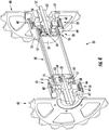
- Figure 3 shows a perspective view of an upper landing portion 20 of a people conveyor 1, in particular an escalator 1a, including a people conveyor drive 25 according to an exemplary embodiment of the invention.
- Figure 3 depicts a portion of the truss 24 of the escalator 1a and a couple of guide rails 22.
- the guide rails 22 are configured for supporting and guiding the rollers 23 (cf. Figure 1 ) of the chain 12 of conveyance elements 13 (not shown in Figure 3 ) of the people conveyor 1.
- the people conveyor drive 25 comprises two sprockets 40.
- Each sprocket 40 is configured for drivingly engaging with a drive element 15 (not shown in Figure 3 ) of the people conveyor 1.
- the drive elements 15 are belts, sheaves may be used instead of sprockets 40.
- the sprockets 40 are arranged coaxially with each other on both lateral sides of the people conveyor 1.
- the sprockets 40 are mechanically connected with each other by a shaft 30 extending orthogonally to the longitudinal conveyance direction of the people conveyor 1.
- a motor 42 is arranged next to each of the sprockets 40, respectively.
- the rotational axes of the motors 42 are oriented coaxially with each other and parallel to the shaft 30 connecting the sprockets 40.
- the motors 42 are arranged between the sprockets 40 and the guide rails 22 in the lateral direction.
- the motors 42 are arranged between the landing portions 20, 21 (cf. Figs. 1 and 2 ) of the people conveyor 1 in the longitudinal conveyance direction.
- the motors 42 do not increase the dimensions of the people conveyor 1, neither in the lateral nor in the longitudinal conveyance direction.
- Each motor 42 drives an output sheave 44. Due to the perspective view, only the output sheave 44 of one of the motors 42 is visible in Figure 3 .
- Each output sheave 44 is drivingly coupled by means of a transmission element 48, for example a transmission belt, to an input sheave 46 arranged coaxially with the shaft 30. Only one input sheave 46 and one transmission element 48 are visible in Figure 3 .
- a transmission element 48 for example a transmission belt
- Each input sheave 46 is mounted to or formed integrally with an input shaft 52 of an axial gearing 50 respectively coupling the input sheave 46 with one of the sprockets 40.
- the axial gearings 50 are arranged coaxially with the shaft 30 between the sprockets 40.
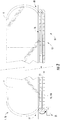
- Figure 4 is a perspective sectional view of the sprockets 40, the shaft 30 and the axial gearings 50
- Figure 5 is a planar sectional view thereof.
- Each axial gearing 50 is a two stage gearing, respectively comprising two planetary gearings 55, 59 arranged within a common housing 51.
- each axial gearing 50 extends rotatably through a torque support 62 and a first planetary carrier 56 of a first planetary gearing 55.
- An inner end of the input shaft 52 opposite to the input sheave 46 (cf. Figure 3 ) is rotatably supported by a cover 53 closing an inner front side of the housing 51.
- a first sun gear 54 is provided next to the inner end of the input shaft 52.
- the first sun gear 54 may be non-rotatably mounted to the input shaft 52.
- the first sun gear 54 may be formed integrally with the input shaft 52.
- the first sun gear 54 is in engagement with first planetary gears 57, in particular three first planetary gears 57, rotatably supported by the first planetary carrier 56.
- the first planetary gears 57 are in engagement with a first internal gear 64 formed on a circular inner wall of the cylindrical housing 51.
- the first planetary carrier 56 is rigidly connected or integrally formed with a second sun gear 58.
- the second sun gear 58 is arranged coaxially with the first sun gear 54 and the input shaft 52.
- the second sun gear 58 is in engagement with second planetary gears 60, in particular three second planetary gears 60.
- the second planetary gears 60 are rotatably supported by a second planetary carrier 61 formed integrally with the torque support 62.
- the torque support 62 is non-rotatably fixed to a stationary portion, i.e. the truss 24, of the people conveyor 1 (cf. Figure 3 ).
- the second planetary gears 60 are in engagement with a second internal gear 66 formed on the inner wall of the cylindrical housing 51.
- each axial gearing 50 rotates with respect to the truss 24 when the input sheaves 46 are rotated by the motors 42 via the transmission elements 48.
- Each housing 51 is non-rotatably connected to or formed integrally with the shaft 30 and one of the sprockets 40.
- each housing 51 acts as an output shaft 51, so that operating the motors 42 results in a rotation of the shaft 30 and the sprockets 40 driving the chain 12 of conveyance elements 13 (not shown in Figs. 3 and 4 ).
- the people conveyor 1 may comprise only one motor 42 and only one axial gearing 50.
- Employing two motors 42 allows for a symmetric distribution of the forces acting on the chain 12 of conveyance elements 13. It further allows using smaller motors 42. It in particular allows using motors 42 fitting between the sprockets 40 or sheaves even in case of large (long) people conveyors 1 and/or people conveyors 1 configured for heavy loads. As a result, even such heavy duty people conveyors 1 may be realized with a small machine room next to one of the landing portions 20, 21 and the overall dimensions may be reduced compared to people conveyors 1 comprising conventional drives.
- the shaft 30 is optional. When provided, the shaft 30 ensures a synchronous rotation of the two sprockets 40 resulting in a symmetric distribution of the forces acting on the chain 12 of conveyance elements 13.
Landscapes
- Escalators And Moving Walkways (AREA)
Abstract
A people conveyor drive (25) includes a motor (42) and an axial gearing (50). The axial gearing (50) comprises an input shaft (52) drivingly coupled to the motor (42); an output shaft (51) configured for driving a people conveyor (1); and a torque support (62) configured for being fixed to a stationary portion of the people conveyor (1). The input shaft (52) and the torque support (62) extend to the same side of the axial gearing (50).
Description
- People conveyors such as escalators and moving walkways are driven by drives comprising at least one machine, in particular an electric motor, placed in a machine room next to one of the landing portions of the people conveyor. The machine room increases the dimensions, in particular the length, of the people conveyor.
- It would be beneficial to provide a drive for a people conveyor (people conveyor drive) which allows reducing the dimensions of the people conveyor.
- According to an exemplary embodiment of the invention, a people conveyor drive comprises a motor and an axial gearing. The axial gearing comprises an input shaft, an output shaft, and a torque support. The input shaft is drivingly coupled to the motor, the output shaft is configured for driving a people conveyor, and the torque support is configured for being fixed to a stationary portion of the people conveyor. The input shaft and the torque support extend to the same side of the axial gearing.
- Exemplary embodiments of the invention further include a people conveyor comprising a truss; a chain of conveyance elements such as pallets or steps; a drive element, such as a drive chain or drive belt extending along a closed loop and being connected to the chain of conveyance elements; a drive sprocket or drive sheave in engagement with the drive element; and a people conveyor drive according to an exemplary embodiment of the invention. The output shaft of the axial gearing is mechanically coupled with the drive sprocket or drive sheave.
- A people conveyor drive according to an exemplary embodiment of the invention allows providing a compact people conveyor drive having smaller dimensions than conventional people conveyor drives. Thus, a people conveyor drive according to an exemplary embodiment of the invention allows reducing the dimensions of people conveyors in which the people conveyor drive is employed.
- A number of optional features are set out in the following. These features may be realized in particular embodiments, alone or in combination with any of the other features.
- The input shaft may extend through the torque support. The torque support in particular may have rotational symmetry, and the input shaft and the torque support may extend coaxially. Such a structure allows for a very compact configuration with the input shaft and the torque support extending to the same side of the axial gearing.
- The output shaft may be provided by a housing of the axial gearing. The housing in particular may by a cylindrical housing having rotational symmetry around an axis, and the axis of the housing / output shaft may extend coaxially with the axis of the input shaft. This allows for a very compact configuration as no separate output shaft needs to be provided.
- The axial gearing may be a planetary gearing, in particular a two-stage planetary gearing. The torque support may be mechanically coupled to a planetary carrier of the planetary gearing. The input shaft may be coupled to a sun gear of the planetary gearing, and an internal gear of the planetary gearing may be formed on an inner wall of the housing. Planetary gears provide compact and robust axial gearings having a high reliability and a long lifetime.
- In alternative embodiments, the axial gearing may be a cyclo gearing, an ellipsoidal gearing or a harmonic drive gearing providing a large reduction ratio with a single stage gearing. A combination of such gearings might be used as well.
- The people conveyor drive may comprise a transmission element, such as a transmission chain or transmission belt, drivingly coupling the motor with the input shaft. Employing a transmission element allows arranging the motor in some distance from the input shaft, in particular non-coaxially with the input shaft. The rotational axis of the motor may be oriented parallel to the rotational axis of the axial gearing in order to reduce the overall dimensions of the people conveyor drive. The transmission belt in particular may be a toothed transmission belt.
- The people conveyor drive may comprise two axial gearings and two motors, wherein each of the motors may be drivingly coupled to the input shaft of one of the two axial gearings, respectively. Such a configuration allows simultaneously driving two drive sprockets or drive sheaves of the people conveyor, in particular two drive sprockets or drive sheaves arranged on opposite lateral sides of the people conveyor.
- The output shafts of the two axial gearings may be mechanically connected with each other. Alternatively, the output shafts of the two axial gearings may be formed integrally with each other. Such a configuration ensures that the drive sprockets or drive sheaves are driven synchronously so that the conveyance elements are driven symmetrically.
- A people conveyor according to an embodiment of the invention may comprise two drive elements, each of the drive elements extending along a closed loop and being connected to the chain of conveyance elements, respectively. The people conveyor may further comprise two drive sprockets or drive sheaves arranged coaxially with each other, each of the two drive sprockets or drive sheaves being in engagement with one of the two drive elements, respectively.
- The output shafts of each axial gearing may be mechanically coupled with one of the drive sprockets or drive sheaves, respectively.
- The output shafts of the axial gearings may be mechanically coupled with each other, or the axial gearings may be formed integrally with each other for commonly driving both drive sprockets or drive sheaves.
- The at least one motor may be arranged between the two drive elements in the lateral direction of the people conveyor. Alternatively or additionally, the at least one motor may be arranged between the two landing portions in the longitudinal conveyance direction of the people conveyor. This allows reducing the dimensions of the people conveyor even further.
- The at least one torque support may be non-rotatably fixed to the truss, in particular by positive form locking.
- The people conveyor may be an escalator in which the conveyance elements are steps. Alternatively, the people conveyor may be a moving walkway in which the conveyance elements are pallets. In a moving walkway, the chain of conveyance elements (pallets) may be inclined with respect to the horizontal, or it may extend horizontally.
- In the following exemplary embodiments of the invention are described with reference to the enclosed figures.
-
Figure 1 depicts a schematic side view of an escalator. -
Figure 2 depicts a schematic side view of a moving walkway. -
Figure 3 shows a perspective view of an upper landing portion of a people conveyor. -
Figure 4 shows a perspective sectional view of two axial gearings according to an exemplary embodiment of the invention. -
Figure 5 shows a planar sectional view of the two axial gearings shown inFigure 4 . -
Figure 1 shows a schematic side view of aconventional people conveyor 1, in particular an escalator 1a, comprising achain 12 of conveyance elements 13 (steps 13a) extending in a longitudinal conveyance direction between twolanding portions rollers 23 guided and supported byguide rails 22. - Only some of the conveyance elements 13 are depicted in
Figure 1 . In turnaround portions next to thelanding portions chain 12 of conveyance elements 13 passes from aconveyance portion 16 into areturn portion 18, and vice versa. Adrive element 15, which may be a chain or a belt, extending along a closed loop is connected to thechain 12 of conveyance elements 13. - The
drive element 15 is driven by asprocket 40 mounted to a rotatingshaft 30. Apeople conveyor drive 25 is configured for driving the rotatingshaft 30 and in consequence thesprocket 40 and thedrive element 15 via atransmission element 48, which may be a transmission chain or a transmission belt. - Balustrades 4 supporting moving handrails 6 extend parallel to the
conveyance portion 16. -
Figure 2 depicts a schematic side view of analternative people conveyor 1, which is provided as a moving walkway 1b. - The moving walkway 1b comprises an
endless chain 12 of conveyance elements 13 (pallets 13b) moving in a longitudinal conveyance direction in anupper conveyance portion 16 and opposite to the conveyance direction in alower return portion 18.Landing portions walkway 1. In turnaround portions next to thelanding portions chain 12 of conveyance elements 13 passes from theconveyance portion 16 into thereturn portion 18, and vice versa. Balustrades 4 supporting moving handrails 6 extend parallel to theconveyance portion 16. - Similar to the embodiment shown in
Figure 1 , thechain 12 of conveyance elements 13 is connected with anendless drive element 15 driven by apeople conveyor drive 25. -
Figure 3 shows a perspective view of anupper landing portion 20 of apeople conveyor 1, in particular an escalator 1a, including a people conveyor drive 25 according to an exemplary embodiment of the invention. -
Figure 3 depicts a portion of thetruss 24 of the escalator 1a and a couple of guide rails 22. The guide rails 22 are configured for supporting and guiding the rollers 23 (cf.Figure 1 ) of thechain 12 of conveyance elements 13 (not shown inFigure 3 ) of thepeople conveyor 1. - The people conveyor drive 25 comprises two
sprockets 40. Eachsprocket 40 is configured for drivingly engaging with a drive element 15 (not shown inFigure 3 ) of thepeople conveyor 1. In case thedrive elements 15 are belts, sheaves may be used instead ofsprockets 40. - The
sprockets 40 are arranged coaxially with each other on both lateral sides of thepeople conveyor 1. Thesprockets 40 are mechanically connected with each other by ashaft 30 extending orthogonally to the longitudinal conveyance direction of thepeople conveyor 1. - A
motor 42 is arranged next to each of thesprockets 40, respectively. The rotational axes of themotors 42 are oriented coaxially with each other and parallel to theshaft 30 connecting thesprockets 40. - The
motors 42 are arranged between thesprockets 40 and the guide rails 22 in the lateral direction. Themotors 42 are arranged between the landingportions 20, 21 (cf.Figs. 1 and2 ) of thepeople conveyor 1 in the longitudinal conveyance direction. - As a result, the
motors 42 do not increase the dimensions of thepeople conveyor 1, neither in the lateral nor in the longitudinal conveyance direction. - Each
motor 42 drives anoutput sheave 44. Due to the perspective view, only theoutput sheave 44 of one of themotors 42 is visible inFigure 3 . - Each
output sheave 44 is drivingly coupled by means of atransmission element 48, for example a transmission belt, to aninput sheave 46 arranged coaxially with theshaft 30. Only oneinput sheave 46 and onetransmission element 48 are visible inFigure 3 . - Each
input sheave 46 is mounted to or formed integrally with aninput shaft 52 of anaxial gearing 50 respectively coupling theinput sheave 46 with one of thesprockets 40. Theaxial gearings 50 are arranged coaxially with theshaft 30 between thesprockets 40. - In the following, the configuration of the
axial gearings 50 is discussed with respect toFigures 4 and5 . -
Figure 4 is a perspective sectional view of thesprockets 40, theshaft 30 and theaxial gearings 50, andFigure 5 is a planar sectional view thereof. - Each
axial gearing 50 is a two stage gearing, respectively comprising twoplanetary gearings common housing 51. - The
input shaft 52 of eachaxial gearing 50 extends rotatably through atorque support 62 and a firstplanetary carrier 56 of a firstplanetary gearing 55. An inner end of theinput shaft 52 opposite to the input sheave 46 (cf.Figure 3 ) is rotatably supported by acover 53 closing an inner front side of thehousing 51. - A
first sun gear 54 is provided next to the inner end of theinput shaft 52. Thefirst sun gear 54 may be non-rotatably mounted to theinput shaft 52. Alternatively, thefirst sun gear 54 may be formed integrally with theinput shaft 52. - The
first sun gear 54 is in engagement with firstplanetary gears 57, in particular three firstplanetary gears 57, rotatably supported by the firstplanetary carrier 56. The firstplanetary gears 57 are in engagement with a firstinternal gear 64 formed on a circular inner wall of thecylindrical housing 51. - The first
planetary carrier 56 is rigidly connected or integrally formed with asecond sun gear 58. Thesecond sun gear 58 is arranged coaxially with thefirst sun gear 54 and theinput shaft 52. - The
second sun gear 58 is in engagement with secondplanetary gears 60, in particular three second planetary gears 60. The secondplanetary gears 60 are rotatably supported by a secondplanetary carrier 61 formed integrally with thetorque support 62. Thetorque support 62 is non-rotatably fixed to a stationary portion, i.e. thetruss 24, of the people conveyor 1 (cf.Figure 3 ). The secondplanetary gears 60 are in engagement with a secondinternal gear 66 formed on the inner wall of thecylindrical housing 51. - In consequence, the
housing 51 of eachaxial gearing 50 rotates with respect to thetruss 24 when the input sheaves 46 are rotated by themotors 42 via thetransmission elements 48. Eachhousing 51 is non-rotatably connected to or formed integrally with theshaft 30 and one of thesprockets 40. - As a result, each
housing 51 acts as anoutput shaft 51, so that operating themotors 42 results in a rotation of theshaft 30 and thesprockets 40 driving thechain 12 of conveyance elements 13 (not shown inFigs. 3 and4 ). - The skilled person understands that in alternative embodiments, which are not shown in the figures, the
people conveyor 1 may comprise only onemotor 42 and only oneaxial gearing 50. - Employing two
motors 42 allows for a symmetric distribution of the forces acting on thechain 12 of conveyance elements 13. It further allows usingsmaller motors 42. It in particular allows usingmotors 42 fitting between thesprockets 40 or sheaves even in case of large (long)people conveyors 1 and/orpeople conveyors 1 configured for heavy loads. As a result, even such heavyduty people conveyors 1 may be realized with a small machine room next to one of thelanding portions people conveyors 1 comprising conventional drives. - The skilled person understands that in embodiments comprising two
motors 42 and twoaxial gearings 50, theshaft 30 is optional. When provided, theshaft 30 ensures a synchronous rotation of the twosprockets 40 resulting in a symmetric distribution of the forces acting on thechain 12 of conveyance elements 13. - While the invention has been described with reference to exemplary embodiments, it will be understood by those skilled in the art that various changes may be made and equivalents may be substituted for elements thereof without departing from the scope of the invention. In addition, many modifications may be made to adopt a particular situation or material to the teachings of the invention without departing from the essential scope thereof. Therefore, it is intended that the invention is not limited to the particular embodiments disclosed, but that the invention includes all embodiments falling within the scope of the claims.
-
- 1
- people conveyor
- 1a
- escalator
- 1b
- moving walkway
- 4
- balustrade
- 6
- moving handrail
- 12
- chain of conveyance elements
- 13
- conveyance elements
- 13a
- steps
- 13b
- pallets
- 15
- drive element
- 16
- conveyance portion
- 18
- return portion
- 20, 21
- landing portions
- 22
- guide rails
- 23
- rollers
- 24
- truss
- 25
- people conveyor drive
- 30
- rotating shaft
- 40
- sprocket
- 42
- motor
- 44
- output sheave
- 46
- input sheave
- 48
- transmission element
- 50
- axial gearing
- 51
- output shaft / housing
- 52
- input shaft
- 53
- cover
- 54
- first sun gear
- 55
- first planetary gearing
- 56
- first planetary carrier
- 57
- first planetary gears
- 58
- second sun gear
- 59
- second planetary gearing
- 60
- second planetary gears
- 61
- second planetary carrier
- 62
- torque support
- 64
- first internal gear
- 66
- second internal gear
Claims (15)
- People conveyor drive (25) including
a motor (42); and
an axial gearing (50) comprising:an input shaft (52) drivingly coupled to the motor (42);an output shaft (51) configured for driving a people conveyor (1); anda torque support (62) configured for being fixed to a stationary portion of the people conveyor (1);wherein the input shaft (52) and the torque support (62) extend to the same side of the axial gearing (50). - People conveyor drive (25) according to claim 1, wherein the input shaft (52) extends through the torque support (62).
- People conveyor drive (25) according to claim 2, wherein the input shaft (52) and the torque support (62) extend coaxially.
- People conveyor drive (25) according to any of the preceding claims, wherein the output shaft (51) is provided by a housing (51) of the axial gearing (50), wherein the output shaft (51) in particular extends coaxially with the input shaft (52).
- People conveyor drive (25) according to any of the preceding claims, wherein the axial gearing (50) comprises a planetary gearing (55, 59), in particular a two-stage planetary gearing (55, 59).
- People conveyor drive (25) according to claim 5, wherein the torque support (62) is mechanically coupled to a planetary carrier (61) of the planetary gearing (59).
- People conveyor drive (25) according to any of claims 1 to 4, wherein the axial gearing (50) comprises any of a cyclo gearing, an ellipsoidal gearing, and a harmonic drive gearing.
- People conveyor drive (25) according to any of the preceding claims, further comprising a transmission element (48), in particular a transmission chain or a transmission belt, drivingly coupling the motor (42) with the input shaft (52).
- People conveyor drive (25) according to any of the preceding claims comprising
two axial gearings (50); and
two motors (42), each of the motors (42) being drivingly coupled to the input shaft (52) of one of the two axial gearings (50), respectively. - People conveyor drive (25) according to claim 9, wherein the output shafts (51) of the two axial gearings (50) are connected with each other or formed integrally with each other.
- People conveyor (1) comprising:a truss (24);a chain (12) of conveyance elements (13);a drive element (15) extending along a closed loop and being connected to the chain (12) of conveyance elements (13);a drive sprocket (40) or drive sheave in engagement with the drive element (15); anda people conveyor drive (25) according to any of claims 1 to 8 wherein the output shaft (51) of the axial gearing (50) is mechanically coupled with the drive sprocket (40) or drive sheave.
- People conveyor (1) comprising:a truss (24);a chain (12) of conveyance elements (13);two drive elements (15), each of the drive elements (15) extending along a closed loop and being connected to the chain (12) of conveyance elements (13);two drive sprockets (40) arranged coaxially with each other, each of the two drive sprockets (40) being in engagement with one of the two drive elements (15), respectively;a people conveyor drive (25) according to claims 1 to 10.
- People conveyor (1) according to claim 12, wherein the at least one motor (42) is arranged between the two drive elements (15).
- People conveyor (1) according to any of claims 11 to 13, wherein the at least one torque support (62) is non-rotatably fixed to the truss (24), in particular by positive form locking.
- People conveyor (1) according to any of claims 11 to 14, wherein the people conveyor (1) is an escalator (1a) or a moving walkway (1b).
Priority Applications (1)
| Application Number | Priority Date | Filing Date | Title |
|---|---|---|---|
| EP18163582.2A EP3543195A1 (en) | 2018-03-23 | 2018-03-23 | People conveyor and drive for a people conveyor |
Applications Claiming Priority (1)
| Application Number | Priority Date | Filing Date | Title |
|---|---|---|---|
| EP18163582.2A EP3543195A1 (en) | 2018-03-23 | 2018-03-23 | People conveyor and drive for a people conveyor |
Publications (1)
| Publication Number | Publication Date |
|---|---|
| EP3543195A1 true EP3543195A1 (en) | 2019-09-25 |
Family
ID=61763871
Family Applications (1)
| Application Number | Title | Priority Date | Filing Date |
|---|---|---|---|
| EP18163582.2A Withdrawn EP3543195A1 (en) | 2018-03-23 | 2018-03-23 | People conveyor and drive for a people conveyor |
Country Status (1)
| Country | Link |
|---|---|
| EP (1) | EP3543195A1 (en) |
Cited By (1)
| Publication number | Priority date | Publication date | Assignee | Title |
|---|---|---|---|---|
| CN113173482A (en) * | 2020-01-24 | 2021-07-27 | 奥的斯电梯公司 | Drive system for people conveyor |
Citations (1)
| Publication number | Priority date | Publication date | Assignee | Title |
|---|---|---|---|---|
| US20080067034A1 (en) * | 2006-09-19 | 2008-03-20 | Thomas Illedits | Escalator or moving walk with drive |
-
2018
- 2018-03-23 EP EP18163582.2A patent/EP3543195A1/en not_active Withdrawn
Patent Citations (1)
| Publication number | Priority date | Publication date | Assignee | Title |
|---|---|---|---|---|
| US20080067034A1 (en) * | 2006-09-19 | 2008-03-20 | Thomas Illedits | Escalator or moving walk with drive |
Cited By (4)
| Publication number | Priority date | Publication date | Assignee | Title |
|---|---|---|---|---|
| CN113173482A (en) * | 2020-01-24 | 2021-07-27 | 奥的斯电梯公司 | Drive system for people conveyor |
| EP3854744A1 (en) * | 2020-01-24 | 2021-07-28 | Otis Elevator Company | Drive systems for people conveyors |
| US11396443B2 (en) | 2020-01-24 | 2022-07-26 | Otis Elevator Company | Drive systems for people conveyors |
| CN113173482B (en) * | 2020-01-24 | 2024-08-20 | 奥的斯电梯公司 | Drive system for a people conveyor |
Similar Documents
| Publication | Publication Date | Title |
|---|---|---|
| AU2007216821B2 (en) | Escalator or moving walk with drive | |
| KR100827048B1 (en) | Escalator drive | |
| EP2341028B1 (en) | Drive system for escalators and moving walkways | |
| KR100991606B1 (en) | Passenger conveyor | |
| US6991084B2 (en) | Handrail-drive for escalator or moving walk | |
| EP3354615A1 (en) | Driving system for driving a conveyer band of a conveyer apparatus | |
| CN101746661A (en) | Passenger delivery device | |
| EP3543194A1 (en) | Drive belt for a people conveyor | |
| JP5969060B2 (en) | Passenger conveyor | |
| JP6238933B2 (en) | Passenger conveyor | |
| CN210944481U (en) | Handrail device for escalator | |
| KR0125893Y1 (en) | Handrail drive equipment of escalator | |
| AU2005242141B2 (en) | Escalator drive machine | |
| JPH03264490A (en) | Escalator | |
| JP2001199664A (en) | Drive device for man conveyer | |
| HK1086242B (en) | Passenger conveyor drive machine | |
| WO2005082768A1 (en) | Travelator, moving ramp or escalator | |
| JPH07149491A (en) | Handrail drive for man conveyor | |
| JP2017007857A (en) | Passenger conveyor |
Legal Events
| Date | Code | Title | Description |
|---|---|---|---|
| PUAI | Public reference made under article 153(3) epc to a published international application that has entered the european phase |
Free format text: ORIGINAL CODE: 0009012 |
|
| AK | Designated contracting states |
Kind code of ref document: A1 Designated state(s): AL AT BE BG CH CY CZ DE DK EE ES FI FR GB GR HR HU IE IS IT LI LT LU LV MC MK MT NL NO PL PT RO RS SE SI SK SM TR |
|
| AX | Request for extension of the european patent |
Extension state: BA ME |
|
| STAA | Information on the status of an ep patent application or granted ep patent |
Free format text: STATUS: THE APPLICATION IS DEEMED TO BE WITHDRAWN |
|
| 18D | Application deemed to be withdrawn |
Effective date: 20200603 |