EP3543135A1 - Heat exchanger blockage detection - Google Patents
Heat exchanger blockage detection Download PDFInfo
- Publication number
- EP3543135A1 EP3543135A1 EP19163716.4A EP19163716A EP3543135A1 EP 3543135 A1 EP3543135 A1 EP 3543135A1 EP 19163716 A EP19163716 A EP 19163716A EP 3543135 A1 EP3543135 A1 EP 3543135A1
- Authority
- EP
- European Patent Office
- Prior art keywords
- ram
- controller
- fan
- heat exchanger
- flow
- Prior art date
- Legal status (The legal status is an assumption and is not a legal conclusion. Google has not performed a legal analysis and makes no representation as to the accuracy of the status listed.)
- Granted
Links
Images

Classifications
-
- B—PERFORMING OPERATIONS; TRANSPORTING
- B64—AIRCRAFT; AVIATION; COSMONAUTICS
- B64D—EQUIPMENT FOR FITTING IN OR TO AIRCRAFT; FLIGHT SUITS; PARACHUTES; ARRANGEMENT OR MOUNTING OF POWER PLANTS OR PROPULSION TRANSMISSIONS IN AIRCRAFT
- B64D13/00—Arrangements or adaptations of air-treatment apparatus for aircraft crew or passengers, or freight space
- B64D13/06—Arrangements or adaptations of air-treatment apparatus for aircraft crew or passengers, or freight space the air being conditioned
-
- F—MECHANICAL ENGINEERING; LIGHTING; HEATING; WEAPONS; BLASTING
- F24—HEATING; RANGES; VENTILATING
- F24F—AIR-CONDITIONING; AIR-HUMIDIFICATION; VENTILATION; USE OF AIR CURRENTS FOR SCREENING
- F24F11/00—Control or safety arrangements
- F24F11/30—Control or safety arrangements for purposes related to the operation of the system, e.g. for safety or monitoring
-
- B—PERFORMING OPERATIONS; TRANSPORTING
- B64—AIRCRAFT; AVIATION; COSMONAUTICS
- B64D—EQUIPMENT FOR FITTING IN OR TO AIRCRAFT; FLIGHT SUITS; PARACHUTES; ARRANGEMENT OR MOUNTING OF POWER PLANTS OR PROPULSION TRANSMISSIONS IN AIRCRAFT
- B64D13/00—Arrangements or adaptations of air-treatment apparatus for aircraft crew or passengers, or freight space
- B64D13/06—Arrangements or adaptations of air-treatment apparatus for aircraft crew or passengers, or freight space the air being conditioned
- B64D13/08—Arrangements or adaptations of air-treatment apparatus for aircraft crew or passengers, or freight space the air being conditioned the air being heated or cooled
-
- F—MECHANICAL ENGINEERING; LIGHTING; HEATING; WEAPONS; BLASTING
- F24—HEATING; RANGES; VENTILATING
- F24F—AIR-CONDITIONING; AIR-HUMIDIFICATION; VENTILATION; USE OF AIR CURRENTS FOR SCREENING
- F24F11/00—Control or safety arrangements
- F24F11/88—Electrical aspects, e.g. circuits
-
- B—PERFORMING OPERATIONS; TRANSPORTING
- B64—AIRCRAFT; AVIATION; COSMONAUTICS
- B64D—EQUIPMENT FOR FITTING IN OR TO AIRCRAFT; FLIGHT SUITS; PARACHUTES; ARRANGEMENT OR MOUNTING OF POWER PLANTS OR PROPULSION TRANSMISSIONS IN AIRCRAFT
- B64D13/00—Arrangements or adaptations of air-treatment apparatus for aircraft crew or passengers, or freight space
- B64D13/06—Arrangements or adaptations of air-treatment apparatus for aircraft crew or passengers, or freight space the air being conditioned
- B64D2013/0603—Environmental Control Systems
- B64D2013/0618—Environmental Control Systems with arrangements for reducing or managing bleed air, using another air source, e.g. ram air
-
- B—PERFORMING OPERATIONS; TRANSPORTING
- B64—AIRCRAFT; AVIATION; COSMONAUTICS
- B64D—EQUIPMENT FOR FITTING IN OR TO AIRCRAFT; FLIGHT SUITS; PARACHUTES; ARRANGEMENT OR MOUNTING OF POWER PLANTS OR PROPULSION TRANSMISSIONS IN AIRCRAFT
- B64D13/00—Arrangements or adaptations of air-treatment apparatus for aircraft crew or passengers, or freight space
- B64D13/06—Arrangements or adaptations of air-treatment apparatus for aircraft crew or passengers, or freight space the air being conditioned
- B64D2013/0603—Environmental Control Systems
- B64D2013/0644—Environmental Control Systems including electric motors or generators
-
- F—MECHANICAL ENGINEERING; LIGHTING; HEATING; WEAPONS; BLASTING
- F24—HEATING; RANGES; VENTILATING
- F24F—AIR-CONDITIONING; AIR-HUMIDIFICATION; VENTILATION; USE OF AIR CURRENTS FOR SCREENING
- F24F2110/00—Control inputs relating to air properties
- F24F2110/40—Pressure, e.g. wind pressure
-
- F—MECHANICAL ENGINEERING; LIGHTING; HEATING; WEAPONS; BLASTING
- F24—HEATING; RANGES; VENTILATING
- F24F—AIR-CONDITIONING; AIR-HUMIDIFICATION; VENTILATION; USE OF AIR CURRENTS FOR SCREENING
- F24F2140/00—Control inputs relating to system states
- F24F2140/60—Energy consumption
-
- F—MECHANICAL ENGINEERING; LIGHTING; HEATING; WEAPONS; BLASTING
- F28—HEAT EXCHANGE IN GENERAL
- F28D—HEAT-EXCHANGE APPARATUS, NOT PROVIDED FOR IN ANOTHER SUBCLASS, IN WHICH THE HEAT-EXCHANGE MEDIA DO NOT COME INTO DIRECT CONTACT
- F28D21/00—Heat-exchange apparatus not covered by any of the groups F28D1/00 - F28D20/00
- F28D2021/0019—Other heat exchangers for particular applications; Heat exchange systems not otherwise provided for
- F28D2021/0021—Other heat exchangers for particular applications; Heat exchange systems not otherwise provided for for aircrafts or cosmonautics
-
- F—MECHANICAL ENGINEERING; LIGHTING; HEATING; WEAPONS; BLASTING
- F28—HEAT EXCHANGE IN GENERAL
- F28G—CLEANING OF INTERNAL OR EXTERNAL SURFACES OF HEAT-EXCHANGE OR HEAT-TRANSFER CONDUITS, e.g. WATER TUBES OR BOILERS
- F28G13/00—Appliances or processes not covered by groups F28G1/00 - F28G11/00; Combinations of appliances or processes covered by groups F28G1/00 - F28G11/00
-
- Y—GENERAL TAGGING OF NEW TECHNOLOGICAL DEVELOPMENTS; GENERAL TAGGING OF CROSS-SECTIONAL TECHNOLOGIES SPANNING OVER SEVERAL SECTIONS OF THE IPC; TECHNICAL SUBJECTS COVERED BY FORMER USPC CROSS-REFERENCE ART COLLECTIONS [XRACs] AND DIGESTS
- Y02—TECHNOLOGIES OR APPLICATIONS FOR MITIGATION OR ADAPTATION AGAINST CLIMATE CHANGE
- Y02T—CLIMATE CHANGE MITIGATION TECHNOLOGIES RELATED TO TRANSPORTATION
- Y02T50/00—Aeronautics or air transport
- Y02T50/50—On board measures aiming to increase energy efficiency
Definitions
- the present invention is related to aircraft environmental control systems, and in particular to a system and method for detecting contamination of heat exchangers within environmental control systems.
- Aircraft often include air conditioning "packs" that, among other things, provide conditioned air for the aircraft. These aircraft may also include one or more ram air fans that draw air through the air conditioning packs while the aircraft is grounded.
- the ram air fan draws air through heat exchangers, which are used to cool air from an aircraft compressed air source, such as a cabin air compressor, for example. Contaminants from the ambient air, as well as larger debris, may cause blockage of the heat exchanger, affecting the air flow through the fan and heat exchangers. Significant heat exchanger contamination can reduce the airflow enough that the ram air fan may operate in an unstable operating mode which may lead to excessive blade stress and in turn, failure of the ram air fan.
- a system includes at least one heat exchanger, a ram fan, and a controller.
- the ram fan is driven by a motor.
- a motor control circuit is configured to provide power to the motor to drive the ram fan.
- the ram fan is configured to provide a ram flow through the at least one heat exchanger from a ram air inlet.
- the controller is configured to determine a blockage level of the at least one heat exchanger based on the power to the motor, a speed of the ram fan, and a temperature of the ram flow at the ram fan.
- a method includes driving, by a motor control circuit, a ram fan to draw a ram flow through at least one heat exchanger; providing, by the motor control circuit, power provided to the motor of the ram fan and a speed of the ram fan to a controller; determining, by the controller, a temperature of the ram flow at the ram fan; and determining a blockage level of the at least one heat exchanger based on the power provided to the motor, the speed of the ram fan, and the temperature of the ram flow.
- An aircraft environmental control system includes a primary heat exchanger, a ram fan, and a controller.
- the primary heat exchanger is configured to provide cooling to a compressed air flow.
- the ram fan is driven by a motor.
- a motor control circuit is configured to provide current to the motor to drive the ram fan.
- the ram fan is configured to draw a ram flow through the primary heat exchanger from a ram air inlet.
- the controller is configured to determine a blockage level of the primary heat exchanger based on the current provided to the motor from the motor control circuit, and a corrected speed of the ram fan.
- a system and method for determining heat exchanger blockage based upon monitored ram fan motor current or power.
- Lab or field data may be utilized to determine an estimated pressure ratio for a ram fan in relation to both the current or power provided to the ram fan and a corrected speed of the ram fan. Based on this determined relationship, during operation of the ram fan, the current or power provided to the ram fan and the speed of the ram fan may be monitored to determine a surge margin of the ram fan. The determined surge margin may be used to determine a heat exchanger blockage level.
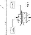
- FIG. 1 is a diagram illustrating environmental control system (ECS) 10.
- System 10 includes ram fan 12, heat exchanger (HX) 14, heat exchangers (HX) 16, motor controller 18, data bus 20, and controller(s) 22.
- Ram fan 12 may be configured to provide a ram air flow through heat exchangers 14 and 16 from ram air inlet 24 to ram air outlet 26.
- Heat exchanger 14, which may be a primary heat exchanger, may be configured to provide air-to-air cooling for a compressed air flow 28.
- the compressed air flow 28 may be received from a cabin air compressor (CAC), bled from a gas turbine engine compressor, or received from another source.
- the cooled air may be provided to other ECS components, such as the components of an air cycle machine (ACM) coupled to ram fan 12.
- Heat exchangers 16 may be secondary heat exchangers, liquid heat exchangers, or a combination thereof, for providing further cooling for air flow within ECS 10.
- ACM air cycle machine
- Ram fan 12 may be driven by motor 30 using motor controller 18.
- motor controller 18 provides electrical power to motor 30, which converts the electrical energy into mechanical rotational energy to drive ram fan 12.
- Controller(s) 22 may, for example, include a pack controller that provides a speed command to motor controller 18.
- Motor controller 18 provides electrical power to motor 30 and adjusts the electrical power until ram fan 12 has reached the commanded speed.
- heat exchangers 14 and 16 may become contaminated or obstructed.
- dirt or other particles such as cotton-wood seeds, may cause contamination of heat exchangers 14 and 16, which can build-up over time.
- larger objects may be injectedthrough ram air inlet 24, fully blocking the flow of ram air through heat exchangers 14 and 16. This contamination can lead to a drop in pressure across heat exchangers 14 and 16, reducing the flow through ram fan 12, which can cause ram fan 12 to operate in an unstable operating mode.
- a pressure difference may be measured across ram fan 12. This pressure difference is used to determine an operating point of the fan, which may then be used to determine a contamination level of heat exchangers 14 and 16. For example, an operating point indicative of a 30% surge margin may be indicative of clean heat exchangers, an 18% surge margin may be indicative of partial, slow contamination of the heat exchangers, a 12% surge margin may be indicative of a full, slow contamination, and 8% surge margin may be indicative of sudden blockage of the heat exchangers. Measuring a pressure difference across ram fan 12 requires extra components and ducting to be installed in system 10. It is desirable to detect contamination of heat exchangers 14 and 16 without the need for installing components to measure the change in pressure across ram fan 12.
- the pressure ratio for ram fan 12 may instead be estimated based on the power or current provided to motor 30 from motor controller 18, as well as a corrected speed of ram fan 12. This is due to the fact that the power provided to motor 30 varies for a given corrected speed of ram fan 12 based on the pressure ratio for ram fan 12. For example, when heat exchangers 14 and 16 become contaminated, the ram flow is impeded, requiring more power to maintain ram fan 12 at the same speed. Thus, the power or current provided to motor 30 may be monitored to determine an operating point of ram fan 12. This relationship can be determined, for example, by analyzing lab data or field data for ram fan 12. The corrected speed may be determined using a temperature at ram air outlet 26 which may be sensed by temperature sensor 32, or estimated by controller(s) 22, for example.
- FIG. 2 is a flowchart illustrating method 100 of determining heat exchanger blockage using ram fan power or current from motor controller 18.
- surge margins with respect to ram fan power or current are determined. This determination may be made through lab data, or through field data, for example.
- heat exchangers of varying levels of contamination, from slightly contaminated to full blockage may be used and the power and/or current to drive ram fan 12 may be monitored and recorded. A relationship may then be established between the corrected speed of ram fan 12 and the power provided to motor 30. The temperature at ram air outlet 26 may be used to determine the corrected speed for ram fan 12.
- This lab data may be utilized to form one or more lookup tables, for example, within a memory of controller(s) 22.
- Each lookup table, or other data structure may be indexed into using a corrected speed of ram fan 12.
- the lookup table may be configured to provide a power or current for a surge margin for the chosen corrected speed. For example, a first lookup table may output a power or current indicative of a 30% surge margin for the entered corrected speed, and a second lookup table may output a power or current indicative of a 12% surge margin for the entered corrected speed.
- These reference power or current obtained from the two lookup tables may then be used to form indicators for heat exchanger blockage. While described with reference to two lookup tables, any number of lookup tables or other data structures may be utilized to generate any number of references for any desired surge margins.
- Deterioration Index P act ⁇ P 30 P 12 ⁇ P 30
- equation [1] is described with reference to power, a similar equation may be utilized for current provided to motor 30.
- the index may then be used to determine a heat exchanger blockage level. For example, if the index is less than 0, then the heat exchanger(s) may be deemed clean. If the index is between 0 and 1, the heat exchanger(s) are becoming contaminated and should be monitored. If the index is greater than 1, the heat exchanger(s) are fully clogged and a maintenance alert should be issued by controller(s) 22 on data bus 20. While described with reference to lookup tables and equation [1], other mathematical relationships for the power/current provided to ram fan 12 and the corrected speed of ram fan 12 may be used to determine a heat exchanger blockage level.
- controller(s) 22 may provide a commanded speed for ram fan 12 to motor controller 18.
- Motor controller 18 provides power to motor 30 to drive ram fan 12 to the commanded speed.
- motor controller 18 provides the present power or current provided to motor 30, and the present speed of ram fan 12, on data bus 20 to controller(s) 22.
- the speed of ram fan 12 may be determined using any method of determining a rotational speed of a fan.
- controller(s) 22 obtain a temperature at ram air outlet 26. This may be accomplished using a direct reading of the temperature from temperature sensor 32, or the temperature may be estimated by controller(s) 22 using aircraft data including, among others, ambient temperature.
- controller(s) 22 use the speed of ram fan 12, the power or current used to drive ram fan 12, and the temperature to determine a heat exchanger deterioration index. This may be accomplished using the above equation [1], or may be accomplished in any other desirable manner.
- step 112 it is determined if the deterioration index is indicative of a contaminated heat exchanger. If so, method 100 proceeds to step 114. If not, method 100 returns to step 102 and resumes normal system operation.
- step 114 it is determined if the index is indicative of full blockage. If so, method 100 proceeds to step 116 and issues an alert. If not, method 100 proceeds to step 118 and monitors the heat exchanger.
- the fan may be commanded to a safe speed or commanded off so as to prevent surge.
- a system includes at least one heat exchanger, a ram fan, and a controller.
- the ram fan is driven by a motor.
- a motor control circuit is configured to provide power to the motor to drive the ram fan.
- the ram fan is configured to provide a ram flow through the at least one heat exchanger from a ram air inlet.
- the controller is configured to determine a blockage level of the at least one heat exchanger based on the power to the motor, a speed of the ram fan, and a temperature of the ram flow at the ram fan.
- the system of the preceding paragraph can optionally include, additionally and/or alternatively, any one or more of the following features, configurations and/or additional components: A further embodiment of the foregoing system, wherein the at least one heat exchanger includes a primary heat exchanger positioned to provide cooling for a compressed air flow using the ram flow; and at least one secondary heat exchanger.
- controller is configured to determine a corrected speed using the speed of the ram fan and the temperature of the ram flow at an inlet to the ram fan.
- a further embodiment of any of the foregoing systems further including a temperature sensor positioned to sense the temperature of the ram flow and provide the temperature of the ram flow at the inlet to the ram fan to the controller.
- controller is further configured to estimate the temperature of the ram flow at the inlet to the ram fan based at least in part on an ambient temperature.
- controller is configured to determine a first reference current using the corrected speed, wherein the first reference current is indicative of a first surge margin condition for the corrected speed, and wherein the controller is further configured to determine a second reference current using the corrected speed, wherein the second reference current is indicative of a second surge margin condition for the corrected speed.
- controller is configured to compare an actual current provided to the ram fan to the first and second reference currents to determine the blockage level of the at least one heat exchanger.
- a further embodiment of any of the foregoing systems wherein the first surge margin condition is a 30% surge margin condition and the second surge margin condition is a 12% surge margin condition.
- controller is configured to determine a first reference power using the corrected speed, wherein the first reference power is indicative of a first surge margin condition for the corrected speed, and wherein the controller is further configured to determine a second reference power using the corrected speed, wherein the second reference power is indicative of a second surge margin condition for the corrected speed, and wherein the controller is configured to compare the power provided to the ram fan to the first and second reference powers to determine the blockage level of the at least one heat exchanger
- a method includes driving, by a motor control circuit, a ram fan to draw a ram flow through at least one heat exchanger; providing, to a controller from the motor control circuit, power provided to a motor of the ram fan and a speed of the ram fan; determining, by the controller, a temperature of the ram flow at the ram fan; and determining a blockage level of the at least one heat exchanger based on the power provided to the motor, the speed of the ram fan, and the temperature of the ram flow.
- the method of the preceding paragraph can optionally include, additionally and/or alternatively, any one or more of the following features, configurations and/or additional components:
- a further embodiment of the foregoing method further includes providing, by a primary heat exchanger and at least one secondary heat exchanger, cooling for a compressed air flow using the ram flow.
- a further embodiment of any of the foregoing methods further including determining, by the controller, a corrected speed using the speed of the ram fan and the temperature of the ram flow.
- determining, by the controller, the temperature of the ram flow at the ram fan comprises sensing, by a temperature sensor positioned in the ram flow, the temperature of the ram flow at the ram fan.
- determining, by the controller, the temperature of the ram flow at the ram fan comprises estimating, by the controller, the ram flow at the ram fan based at least in part on an ambient temperature.
- An aircraft environmental control system includes a primary heat exchanger, a ram fan, and a controller.
- the primary heat exchanger is configured to provide cooling to a compressed air flow.
- the ram fan is driven by a motor.
- a motor control circuit is configured to provide current to the motor to drive the ram fan.
- the ram fan is configured to draw a ram flow through the primary heat exchanger from a ram air inlet.
- the controller is configured to determine a blockage level of the primary heat exchanger based on the current provided to the motor from the motor control circuit, and a corrected speed of the ram fan.
- the aircraft environmental control system of the preceding paragraph can optionally include, additionally and/or alternatively, any one or more of the following features, configurations and/or additional components:
- a further embodiment of the foregoing aircraft environmental control system wherein the controller is configured to determine the blockage level for the primary heat exchanger by comparing the current provided to the motor to a first reference current and a second reference current, wherein the first reference current is indicative of a first surge margin condition for the corrected speed and the second reference current is indicative of a second surge margin condition for the corrected speed.
Landscapes
- Engineering & Computer Science (AREA)
- Health & Medical Sciences (AREA)
- General Health & Medical Sciences (AREA)
- Pulmonology (AREA)
- Aviation & Aerospace Engineering (AREA)
- Chemical & Material Sciences (AREA)
- Combustion & Propulsion (AREA)
- Mechanical Engineering (AREA)
- General Engineering & Computer Science (AREA)
- Control Of Positive-Displacement Air Blowers (AREA)
- Control Of Electric Motors In General (AREA)
Abstract
Description
- The present invention is related to aircraft environmental control systems, and in particular to a system and method for detecting contamination of heat exchangers within environmental control systems.
- Aircraft often include air conditioning "packs" that, among other things, provide conditioned air for the aircraft. These aircraft may also include one or more ram air fans that draw air through the air conditioning packs while the aircraft is grounded. In many systems, the ram air fan draws air through heat exchangers, which are used to cool air from an aircraft compressed air source, such as a cabin air compressor, for example. Contaminants from the ambient air, as well as larger debris, may cause blockage of the heat exchanger, affecting the air flow through the fan and heat exchangers. Significant heat exchanger contamination can reduce the airflow enough that the ram air fan may operate in an unstable operating mode which may lead to excessive blade stress and in turn, failure of the ram air fan.
- A system includes at least one heat exchanger, a ram fan, and a controller. The ram fan is driven by a motor. A motor control circuit is configured to provide power to the motor to drive the ram fan. The ram fan is configured to provide a ram flow through the at least one heat exchanger from a ram air inlet. The controller is configured to determine a blockage level of the at least one heat exchanger based on the power to the motor, a speed of the ram fan, and a temperature of the ram flow at the ram fan.
- A method includes driving, by a motor control circuit, a ram fan to draw a ram flow through at least one heat exchanger; providing, by the motor control circuit, power provided to the motor of the ram fan and a speed of the ram fan to a controller; determining, by the controller, a temperature of the ram flow at the ram fan; and determining a blockage level of the at least one heat exchanger based on the power provided to the motor, the speed of the ram fan, and the temperature of the ram flow.
- An aircraft environmental control system includes a primary heat exchanger, a ram fan, and a controller. The primary heat exchanger is configured to provide cooling to a compressed air flow. The ram fan is driven by a motor. A motor control circuit is configured to provide current to the motor to drive the ram fan. The ram fan is configured to draw a ram flow through the primary heat exchanger from a ram air inlet. The controller is configured to determine a blockage level of the primary heat exchanger based on the current provided to the motor from the motor control circuit, and a corrected speed of the ram fan.
-
-
FIG. 1 is a block diagram illustrating an environmental control system. -
FIG. 2 is a flowchart illustrating a method of determining heat exchanger blockage in environmental control systems. - A system and method is disclosed herein for determining heat exchanger blockage based upon monitored ram fan motor current or power. Lab or field data may be utilized to determine an estimated pressure ratio for a ram fan in relation to both the current or power provided to the ram fan and a corrected speed of the ram fan. Based on this determined relationship, during operation of the ram fan, the current or power provided to the ram fan and the speed of the ram fan may be monitored to determine a surge margin of the ram fan. The determined surge margin may be used to determine a heat exchanger blockage level.
-
FIG. 1 is a diagram illustrating environmental control system (ECS) 10.System 10 includesram fan 12, heat exchanger (HX) 14, heat exchangers (HX) 16,motor controller 18,data bus 20, and controller(s) 22. Ramfan 12 may be configured to provide a ram air flow throughheat exchangers ram air inlet 24 toram air outlet 26.Heat exchanger 14, which may be a primary heat exchanger, may be configured to provide air-to-air cooling for acompressed air flow 28. Thecompressed air flow 28 may be received from a cabin air compressor (CAC), bled from a gas turbine engine compressor, or received from another source. The cooled air may be provided to other ECS components, such as the components of an air cycle machine (ACM) coupled toram fan 12.Heat exchangers 16 may be secondary heat exchangers, liquid heat exchangers, or a combination thereof, for providing further cooling for air flow withinECS 10. - Ram
fan 12 may be driven bymotor 30 usingmotor controller 18. For example,motor controller 18 provides electrical power to motor 30, which converts the electrical energy into mechanical rotational energy to driveram fan 12. Controller(s) 22 may, for example, include a pack controller that provides a speed command tomotor controller 18.Motor controller 18 provides electrical power to motor 30 and adjusts the electrical power untilram fan 12 has reached the commanded speed. - Over time,
heat exchangers heat exchangers ram air inlet 24, fully blocking the flow of ram air throughheat exchangers heat exchangers ram fan 12, which can causeram fan 12 to operate in an unstable operating mode. - In other systems, a pressure difference may be measured across
ram fan 12. This pressure difference is used to determine an operating point of the fan, which may then be used to determine a contamination level ofheat exchangers ram fan 12 requires extra components and ducting to be installed insystem 10. It is desirable to detect contamination ofheat exchangers ram fan 12. - The pressure ratio for
ram fan 12 may instead be estimated based on the power or current provided to motor 30 frommotor controller 18, as well as a corrected speed ofram fan 12. This is due to the fact that the power provided tomotor 30 varies for a given corrected speed ofram fan 12 based on the pressure ratio forram fan 12. For example, whenheat exchangers ram fan 12 at the same speed. Thus, the power or current provided tomotor 30 may be monitored to determine an operating point ofram fan 12. This relationship can be determined, for example, by analyzing lab data or field data forram fan 12. The corrected speed may be determined using a temperature atram air outlet 26 which may be sensed bytemperature sensor 32, or estimated by controller(s) 22, for example. - With continued reference to
FIG. 1 ,FIG. 2 is a flowchartillustrating method 100 of determining heat exchanger blockage using ram fan power or current frommotor controller 18. Atstep 102, surge margins with respect to ram fan power or current are determined. This determination may be made through lab data, or through field data, for example. For lab data, heat exchangers of varying levels of contamination, from slightly contaminated to full blockage, may be used and the power and/or current to driveram fan 12 may be monitored and recorded. A relationship may then be established between the corrected speed ofram fan 12 and the power provided tomotor 30. The temperature atram air outlet 26 may be used to determine the corrected speed forram fan 12. - This lab data may be utilized to form one or more lookup tables, for example, within a memory of controller(s) 22. Each lookup table, or other data structure, may be indexed into using a corrected speed of
ram fan 12. The lookup table may be configured to provide a power or current for a surge margin for the chosen corrected speed. For example, a first lookup table may output a power or current indicative of a 30% surge margin for the entered corrected speed, and a second lookup table may output a power or current indicative of a 12% surge margin for the entered corrected speed. These reference power or current obtained from the two lookup tables may then be used to form indicators for heat exchanger blockage. While described with reference to two lookup tables, any number of lookup tables or other data structures may be utilized to generate any number of references for any desired surge margins. - In one example embodiment, the following equation may be utilized to generate a heat exchanger deterioration index based upon the two references obtained using the corrected speed:

- Pact = The actual power being provided to
motor 30 frommotor controller 18; - P30 = The reference power for the present corrected speed of
ram fan 12 that corresponds to a 30% surge margin; and - P12 = The reference power for the present corrected speed of
ram fan 12 that corresponds to a 12% surge margin. - Note that while equation [1] is described with reference to power, a similar equation may be utilized for current provided to
motor 30. The index may then be used to determine a heat exchanger blockage level. For example, if the index is less than 0, then the heat exchanger(s) may be deemed clean. If the index is between 0 and 1, the heat exchanger(s) are becoming contaminated and should be monitored. If the index is greater than 1, the heat exchanger(s) are fully clogged and a maintenance alert should be issued by controller(s) 22 ondata bus 20. While described with reference to lookup tables and equation [1], other mathematical relationships for the power/current provided to ramfan 12 and the corrected speed ofram fan 12 may be used to determine a heat exchanger blockage level. - At
step 104, controller(s) 22 may provide a commanded speed forram fan 12 tomotor controller 18.Motor controller 18 provides power tomotor 30 to driveram fan 12 to the commanded speed. Atstep 106,motor controller 18 provides the present power or current provided tomotor 30, and the present speed ofram fan 12, ondata bus 20 to controller(s) 22. The speed ofram fan 12 may be determined using any method of determining a rotational speed of a fan. Atstep 108, controller(s) 22 obtain a temperature atram air outlet 26. This may be accomplished using a direct reading of the temperature fromtemperature sensor 32, or the temperature may be estimated by controller(s) 22 using aircraft data including, among others, ambient temperature. - At
step 110, controller(s) 22 use the speed ofram fan 12, the power or current used to driveram fan 12, and the temperature to determine a heat exchanger deterioration index. This may be accomplished using the above equation [1], or may be accomplished in any other desirable manner. Atstep 112, it is determined if the deterioration index is indicative of a contaminated heat exchanger. If so,method 100 proceeds to step 114. If not,method 100 returns to step 102 and resumes normal system operation. Atstep 114, it is determined if the index is indicative of full blockage. If so,method 100 proceeds to step 116 and issues an alert. If not,method 100 proceeds to step 118 and monitors the heat exchanger. Atstep 116, the fan may be commanded to a safe speed or commanded off so as to prevent surge. - A system includes at least one heat exchanger, a ram fan, and a controller. The ram fan is driven by a motor. A motor control circuit is configured to provide power to the motor to drive the ram fan. The ram fan is configured to provide a ram flow through the at least one heat exchanger from a ram air inlet. The controller is configured to determine a blockage level of the at least one heat exchanger based on the power to the motor, a speed of the ram fan, and a temperature of the ram flow at the ram fan.
- The system of the preceding paragraph can optionally include, additionally and/or alternatively, any one or more of the following features, configurations and/or additional components:
A further embodiment of the foregoing system, wherein the at least one heat exchanger includes a primary heat exchanger positioned to provide cooling for a compressed air flow using the ram flow; and at least one secondary heat exchanger. - A further embodiment of any of the foregoing systems, wherein the controller is configured to determine a corrected speed using the speed of the ram fan and the temperature of the ram flow at an inlet to the ram fan.
- A further embodiment of any of the foregoing systems, further including a temperature sensor positioned to sense the temperature of the ram flow and provide the temperature of the ram flow at the inlet to the ram fan to the controller.
- A further embodiment of any of the foregoing systems, wherein the controller is further configured to estimate the temperature of the ram flow at the inlet to the ram fan based at least in part on an ambient temperature.
- A further embodiment of any of the foregoing systems, wherein the controller is configured to determine a first reference current using the corrected speed, wherein the first reference current is indicative of a first surge margin condition for the corrected speed, and wherein the controller is further configured to determine a second reference current using the corrected speed, wherein the second reference current is indicative of a second surge margin condition for the corrected speed.
- A further embodiment of any of the foregoing systems, wherein the controller is configured to compare an actual current provided to the ram fan to the first and second reference currents to determine the blockage level of the at least one heat exchanger.
- A further embodiment of any of the foregoing systems, wherein the first surge margin condition is a 30% surge margin condition and the second surge margin condition is a 12% surge margin condition.
- A further embodiment of any of the foregoing systems, wherein the controller is configured to determine a first reference power using the corrected speed, wherein the first reference power is indicative of a first surge margin condition for the corrected speed, and wherein the controller is further configured to determine a second reference power using the corrected speed, wherein the second reference power is indicative of a second surge margin condition for the corrected speed, and wherein the controller is configured to compare the power provided to the ram fan to the first and second reference powers to determine the blockage level of the at least one heat exchanger
- A method includes driving, by a motor control circuit, a ram fan to draw a ram flow through at least one heat exchanger; providing, to a controller from the motor control circuit, power provided to a motor of the ram fan and a speed of the ram fan; determining, by the controller, a temperature of the ram flow at the ram fan; and determining a blockage level of the at least one heat exchanger based on the power provided to the motor, the speed of the ram fan, and the temperature of the ram flow.
- The method of the preceding paragraph can optionally include, additionally and/or alternatively, any one or more of the following features, configurations and/or additional components:
- A further embodiment of the foregoing method, further includes providing, by a primary heat exchanger and at least one secondary heat exchanger, cooling for a compressed air flow using the ram flow.
- A further embodiment of any of the foregoing methods, further including determining, by the controller, a corrected speed using the speed of the ram fan and the temperature of the ram flow.
- A further embodiment of any of the foregoing methods, wherein determining, by the controller, the temperature of the ram flow at the ram fan comprises sensing, by a temperature sensor positioned in the ram flow, the temperature of the ram flow at the ram fan.
- A further embodiment of any of the foregoing methods, wherein determining, by the controller, the temperature of the ram flow at the ram fan comprises estimating, by the controller, the ram flow at the ram fan based at least in part on an ambient temperature.
- An aircraft environmental control system includes a primary heat exchanger, a ram fan, and a controller. The primary heat exchanger is configured to provide cooling to a compressed air flow. The ram fan is driven by a motor. A motor control circuit is configured to provide current to the motor to drive the ram fan. The ram fan is configured to draw a ram flow through the primary heat exchanger from a ram air inlet. The controller is configured to determine a blockage level of the primary heat exchanger based on the current provided to the motor from the motor control circuit, and a corrected speed of the ram fan.
- The aircraft environmental control system of the preceding paragraph can optionally include, additionally and/or alternatively, any one or more of the following features, configurations and/or additional components:
A further embodiment of the foregoing aircraft environmental control system, wherein the controller is configured to determine the blockage level for the primary heat exchanger by comparing the current provided to the motor to a first reference current and a second reference current, wherein the first reference current is indicative of a first surge margin condition for the corrected speed and the second reference current is indicative of a second surge margin condition for the corrected speed. - While the invention has been described with reference to an exemplary embodiment(s), it will be understood by those skilled in the art that various changes may be made and equivalents may be substituted for elements thereof without departing from the scope of the invention. In addition, many modifications may be made to adapt a particular situation or material to the teachings of the invention without departing from the scope thereof. Therefore, it is intended that the invention not be limited to the particular embodiment(s) disclosed, but that the invention will include all embodiments falling within the scope of the appended claims.
Claims (15)
- A system comprising:at least one heat exchanger (14, 16);a ram fan (12) driven by a motor (30), wherein a motor control circuit (18) is configured to provide power to the motor to drive the ram fan, wherein the ram fan is configured to provide a ram flow through the at least one heat exchanger from a ram air inlet (24); anda controller (22) configured to determine a blockage level of the at least one heat exchanger based on the power to the motor, a speed of the ram fan, and a temperature of the ram flow at the ram fan.
- The system of claim 1, wherein the at least one heat exchanger comprises:a primary heat exchanger positioned to provide cooling for a compressed air flow using the ram flow; andat least one secondary heat exchanger.
- The system of 1 or 2, wherein the controller is configured to determine a corrected speed using the speed of the ram fan and the temperature of the ram flow at an inlet to the ram fan.
- The system of claim 3, further comprising a temperature sensor (32) positioned to sense the temperature of the ram flow and provide the temperature of the ram flow at the inlet to the ram fan to the controller, or wherein the controller is further configured to estimate the temperature of the ram flow at the inlet to the ram fan based at least in part on an ambient temperature.
- The system of claim 3, wherein the controller is configured to determine a first reference current using the corrected speed, wherein the first reference current is indicative of a first surge margin condition for the corrected speed, and wherein the controller is further configured to determine a second reference current using the corrected speed, wherein the second reference current is indicative of a second surge margin condition for the corrected speed, and preferably wherein the controller is configured to compare an actual current provided to the ram fan to the first and second reference currents to determine the blockage level of the at least one heat exchanger.
- The system of claim 5, wherein the first surge margin condition is a 30% surge margin condition and the second surge margin condition is a 12% surge margin condition.
- The system of claim 3, wherein the controller is configured to determine a first reference power using the corrected speed, wherein the first reference power is indicative of a first surge margin condition for the corrected speed, and wherein the controller is further configured to determine a second reference power using the corrected speed, wherein the second reference power is indicative of a second surge margin condition for the corrected speed, and wherein the controller is configured to compare the power provided to the ram fan to the first and second reference powers to determine the blockage level of the at least one heat exchanger
- A method comprising:driving, by a motor control circuit, a ram fan to draw a ram flow through at least one heat exchanger;providing, to a controller from the motor control circuit, power provided to a motor of the ram fan, and a speed of the ram fan;determining, by the controller, a temperature of the ram flow at the ram fan; anddetermining a blockage level of the at least one heat exchanger based on the power provided to the motor, the speed of the ram fan, and the temperature of the ram flow.
- The method of claim 8, further comprising:
providing, by a primary heat exchanger and at least one secondary heat exchanger, cooling for a compressed air flow using the ram flow. - The method of 8, further comprising:
determining, by the controller, a corrected speed using the speed of the ram fan and the temperature of the ram flow. - The method of claim 10, wherein the determining, by the controller, the temperature of the ram flow at the ram fan comprises sensing, by a temperature sensor positioned in the ram flow, the temperature of the ram flow at the ram fan, or wherein the determining, by the controller, the temperature of the ram flow at the ram fan comprises estimating, by the controller, the ram flow at the ram fan based at least in part on an ambient temperature.
- The method of claim 10 or 11, further comprising:determining, by the controller, a first reference current using the corrected speed, wherein the first reference current is indicative of a first surge margin condition for the corrected speed; anddetermining, by the controller, a second reference current using the corrected speed, wherein the second reference current is indicative of a second surge margin condition for the corrected speed, and preferably wherein the determining the blockage level of the at least one heat exchanger comprises comparing, by the controller, an actual current provided to the ram fan to the first and second reference currents to determine the blockage level of the at least one heat exchanger, and preferably wherein the first surge margin condition is a 30% surge margin condition and the second surge margin condition is a 12% surge margin condition.
- The method of claim 10, further comprising:determining, by the controller, a first reference power using the corrected speed, wherein the first reference power is indicative of a first surge margin condition for the corrected speed; anddetermining, by the controller, a second reference power using the corrected speed, wherein the second reference power is indicative of a second surge margin condition for the corrected speed;wherein determining the blockage level of the at least one heat exchanger comprises comparing, by the controller, the power provided to the ram fan to the first and second reference powers to determine the blockage level of the at least one heat exchanger.
- An aircraft environmental control system comprising:a primary heat exchanger (14) configured to provide cooling to a compressed air flow;a ram fan (12) driven by a motor (30), wherein a motor control circuit (18) is configured to provide current to the motor to drive the ram fan, wherein the ram fan is configured to draw a ram flow through the primary heat exchanger from a ram air inlet (24); anda controller (22) configured to determine a blockage level of the primary heat exchanger based on the current provided to the motor from the motor control circuit, and a corrected speed of the ram fan.
- The aircraft environmental control system of claim 14, wherein the controller is configured to determine the blockage level for the primary heat exchanger by comparing the current provided to the motor to a first reference current and a second reference current, wherein the first reference current is indicative of a first surge margin condition for the corrected speed and the second reference current is indicative of a second surge margin condition for the corrected speed.
Applications Claiming Priority (1)
| Application Number | Priority Date | Filing Date | Title |
|---|---|---|---|
| US15/925,060 US10690366B2 (en) | 2018-03-19 | 2018-03-19 | Heat exchanger blockage detection |
Publications (2)
| Publication Number | Publication Date |
|---|---|
| EP3543135A1 true EP3543135A1 (en) | 2019-09-25 |
| EP3543135B1 EP3543135B1 (en) | 2024-04-24 |
Family
ID=65903944
Family Applications (1)
| Application Number | Title | Priority Date | Filing Date |
|---|---|---|---|
| EP19163716.4A Active EP3543135B1 (en) | 2018-03-19 | 2019-03-19 | Heat exchanger blockage detection |
Country Status (2)
| Country | Link |
|---|---|
| US (1) | US10690366B2 (en) |
| EP (1) | EP3543135B1 (en) |
Families Citing this family (3)
| Publication number | Priority date | Publication date | Assignee | Title |
|---|---|---|---|---|
| CN112283870B (en) * | 2020-10-30 | 2021-11-23 | 广东Tcl智能暖通设备有限公司 | Air conditioner outdoor unit control method and system and computer readable storage medium |
| DE102023102297A1 (en) | 2022-02-01 | 2023-08-10 | Regal Beloit America, Inc. | Blocked coil detection system |
| EP4494906A1 (en) * | 2023-07-17 | 2025-01-22 | Volvo Car Corporation | A method for determining condition data indicative of a blockage of a thermal unit of a heat pump system of a vehicle |
Citations (4)
| Publication number | Priority date | Publication date | Assignee | Title |
|---|---|---|---|---|
| US20130291651A1 (en) * | 2011-01-10 | 2013-11-07 | Airbus Operations Gmbh | Method and device for determining an air mass flow flowing through a ram air channel |
| EP2792960A1 (en) * | 2013-04-16 | 2014-10-22 | Hamilton Sundstrand Corporation | Method of monitoring a heat exchanger arrangement and heat exchanger monitoring system |
| US20150166186A1 (en) * | 2013-12-18 | 2015-06-18 | Hamilton Sundstrand Corporation | Aircraft air-conditioning heat exchanger contamination detection |
| US20180051945A1 (en) * | 2016-08-18 | 2018-02-22 | The Boeing Company | Model-based method and system to detect heat exchanger fouling |
Family Cites Families (8)
| Publication number | Priority date | Publication date | Assignee | Title |
|---|---|---|---|---|
| US5596271A (en) * | 1994-05-03 | 1997-01-21 | Multicraft International | Method of and apparatus for detecting the rotation rate of an air moving fan |
| US6023138A (en) * | 1997-09-11 | 2000-02-08 | International Business Machines Corporation | Fan venturi blockage detection |
| US7729688B2 (en) | 2003-12-08 | 2010-06-01 | Ipventure, Inc. | Systems and processes to manage multiple modes of communication |
| US7261762B2 (en) * | 2004-05-06 | 2007-08-28 | Carrier Corporation | Technique for detecting and predicting air filter condition |
| US9816720B2 (en) * | 2014-11-26 | 2017-11-14 | Hamilton Sundstrand Corporation | Heat exchanger contamination monitoring |
| US9988153B2 (en) | 2015-07-13 | 2018-06-05 | Hamilton Sundstrand Space Systems | RAF bit for surge detection |
| US10346585B2 (en) * | 2016-02-22 | 2019-07-09 | Hamilton Sundstrand Corporation | Method of predicting heat exchanger blockage via ram air fan surge margin |
| US9896089B2 (en) * | 2016-04-07 | 2018-02-20 | Ford Global Technologies, Llc | Methods and systems for adjusting engine operation based on weather data |
-
2018
- 2018-03-19 US US15/925,060 patent/US10690366B2/en active Active
-
2019
- 2019-03-19 EP EP19163716.4A patent/EP3543135B1/en active Active
Patent Citations (4)
| Publication number | Priority date | Publication date | Assignee | Title |
|---|---|---|---|---|
| US20130291651A1 (en) * | 2011-01-10 | 2013-11-07 | Airbus Operations Gmbh | Method and device for determining an air mass flow flowing through a ram air channel |
| EP2792960A1 (en) * | 2013-04-16 | 2014-10-22 | Hamilton Sundstrand Corporation | Method of monitoring a heat exchanger arrangement and heat exchanger monitoring system |
| US20150166186A1 (en) * | 2013-12-18 | 2015-06-18 | Hamilton Sundstrand Corporation | Aircraft air-conditioning heat exchanger contamination detection |
| US20180051945A1 (en) * | 2016-08-18 | 2018-02-22 | The Boeing Company | Model-based method and system to detect heat exchanger fouling |
Also Published As
| Publication number | Publication date |
|---|---|
| EP3543135B1 (en) | 2024-04-24 |
| US10690366B2 (en) | 2020-06-23 |
| US20190285297A1 (en) | 2019-09-19 |
Similar Documents
| Publication | Publication Date | Title |
|---|---|---|
| US9862495B2 (en) | Aircraft air-conditioning heat exchanger contamination detection | |
| EP3539874B1 (en) | Heat exchanger blockage detection to prevent ram air fan surge | |
| EP3543135B1 (en) | Heat exchanger blockage detection | |
| CN105275856B (en) | The system and method that control is used for the air blower of fuel-cell vehicle | |
| US9200995B2 (en) | Method and apparatus for monitoring air filter condition | |
| CN103376743B (en) | A constant air volume control method for a motor and an air-conditioning fan system | |
| US8830079B2 (en) | Low air conditioning refrigerant detection method | |
| US10989428B2 (en) | Performance diagnosis device and performance diagnosis method for air conditioner | |
| EP1880940A1 (en) | System and method for controlling compressor flow | |
| EP3232283B1 (en) | Flow sensor bit for motor driven compressor | |
| KR101160425B1 (en) | Method for Filter Clogging Detection in Air Conditioner | |
| US20130055890A1 (en) | Apparatus and method for filtering cooling duct of battery for electric vehicle | |
| US20030228229A1 (en) | Screw compressor | |
| CN119435449B (en) | Cooling fan intelligent control system based on data acquisition | |
| US9988153B2 (en) | RAF bit for surge detection | |
| JP2006523805A (en) | Surge detection method for centrifugal compressor | |
| EP4596887A1 (en) | Control device and program | |
| JPH08121381A (en) | Ventilation system for vehicles | |
| JPH11118232A (en) | Air conditioner | |
| CN224006962U (en) | Heat dissipation system for frequency converter, frequency converter and fracturing system | |
| CN115515392B (en) | Method for formulating charger cooling system and speed regulation strategy | |
| US12241473B2 (en) | Methods and systems of compressor control with surge avoidance and response | |
| CN118376045A (en) | Method and device for detecting fan faults of refrigerating system | |
| EP3026991A1 (en) | Conditioning unit of the indirect free cooling type, method of operation of such a conditioning unit, and apparatus for carrying out such method | |
| KR20060104295A (en) | Altitude measuring device and method, and cooling device and cooling method using altitude measurement |
Legal Events
| Date | Code | Title | Description |
|---|---|---|---|
| PUAI | Public reference made under article 153(3) epc to a published international application that has entered the european phase |
Free format text: ORIGINAL CODE: 0009012 |
|
| STAA | Information on the status of an ep patent application or granted ep patent |
Free format text: STATUS: THE APPLICATION HAS BEEN PUBLISHED |
|
| AK | Designated contracting states |
Kind code of ref document: A1 Designated state(s): AL AT BE BG CH CY CZ DE DK EE ES FI FR GB GR HR HU IE IS IT LI LT LU LV MC MK MT NL NO PL PT RO RS SE SI SK SM TR |
|
| AX | Request for extension of the european patent |
Extension state: BA ME |
|
| STAA | Information on the status of an ep patent application or granted ep patent |
Free format text: STATUS: REQUEST FOR EXAMINATION WAS MADE |
|
| 17P | Request for examination filed |
Effective date: 20191120 |
|
| RBV | Designated contracting states (corrected) |
Designated state(s): AL AT BE BG CH CY CZ DE DK EE ES FI FR GB GR HR HU IE IS IT LI LT LU LV MC MK MT NL NO PL PT RO RS SE SI SK SM TR |
|
| STAA | Information on the status of an ep patent application or granted ep patent |
Free format text: STATUS: EXAMINATION IS IN PROGRESS |
|
| 17Q | First examination report despatched |
Effective date: 20210209 |
|
| GRAP | Despatch of communication of intention to grant a patent |
Free format text: ORIGINAL CODE: EPIDOSNIGR1 |
|
| STAA | Information on the status of an ep patent application or granted ep patent |
Free format text: STATUS: GRANT OF PATENT IS INTENDED |
|
| INTG | Intention to grant announced |
Effective date: 20231116 |
|
| GRAS | Grant fee paid |
Free format text: ORIGINAL CODE: EPIDOSNIGR3 |
|
| GRAA | (expected) grant |
Free format text: ORIGINAL CODE: 0009210 |
|
| STAA | Information on the status of an ep patent application or granted ep patent |
Free format text: STATUS: THE PATENT HAS BEEN GRANTED |
|
| AK | Designated contracting states |
Kind code of ref document: B1 Designated state(s): AL AT BE BG CH CY CZ DE DK EE ES FI FR GB GR HR HU IE IS IT LI LT LU LV MC MK MT NL NO PL PT RO RS SE SI SK SM TR |
|
| REG | Reference to a national code |
Ref country code: GB Ref legal event code: FG4D |
|
| REG | Reference to a national code |
Ref country code: CH Ref legal event code: EP |
|
| REG | Reference to a national code |
Ref country code: DE Ref legal event code: R096 Ref document number: 602019050727 Country of ref document: DE |
|
| REG | Reference to a national code |
Ref country code: IE Ref legal event code: FG4D |
|
| REG | Reference to a national code |
Ref country code: LT Ref legal event code: MG9D |
|
| REG | Reference to a national code |
Ref country code: NL Ref legal event code: MP Effective date: 20240424 |
|
| REG | Reference to a national code |
Ref country code: AT Ref legal event code: MK05 Ref document number: 1679349 Country of ref document: AT Kind code of ref document: T Effective date: 20240424 |
|
| PG25 | Lapsed in a contracting state [announced via postgrant information from national office to epo] |
Ref country code: NL Free format text: LAPSE BECAUSE OF FAILURE TO SUBMIT A TRANSLATION OF THE DESCRIPTION OR TO PAY THE FEE WITHIN THE PRESCRIBED TIME-LIMIT Effective date: 20240424 |
|
| PG25 | Lapsed in a contracting state [announced via postgrant information from national office to epo] |
Ref country code: NL Free format text: LAPSE BECAUSE OF FAILURE TO SUBMIT A TRANSLATION OF THE DESCRIPTION OR TO PAY THE FEE WITHIN THE PRESCRIBED TIME-LIMIT Effective date: 20240424 |
|
| PG25 | Lapsed in a contracting state [announced via postgrant information from national office to epo] |
Ref country code: IS Free format text: LAPSE BECAUSE OF FAILURE TO SUBMIT A TRANSLATION OF THE DESCRIPTION OR TO PAY THE FEE WITHIN THE PRESCRIBED TIME-LIMIT Effective date: 20240824 |
|
| PG25 | Lapsed in a contracting state [announced via postgrant information from national office to epo] |
Ref country code: BG Free format text: LAPSE BECAUSE OF FAILURE TO SUBMIT A TRANSLATION OF THE DESCRIPTION OR TO PAY THE FEE WITHIN THE PRESCRIBED TIME-LIMIT Effective date: 20240424 |
|
| PG25 | Lapsed in a contracting state [announced via postgrant information from national office to epo] |
Ref country code: FI Free format text: LAPSE BECAUSE OF FAILURE TO SUBMIT A TRANSLATION OF THE DESCRIPTION OR TO PAY THE FEE WITHIN THE PRESCRIBED TIME-LIMIT Effective date: 20240424 Ref country code: HR Free format text: LAPSE BECAUSE OF FAILURE TO SUBMIT A TRANSLATION OF THE DESCRIPTION OR TO PAY THE FEE WITHIN THE PRESCRIBED TIME-LIMIT Effective date: 20240424 |
|
| PG25 | Lapsed in a contracting state [announced via postgrant information from national office to epo] |
Ref country code: GR Free format text: LAPSE BECAUSE OF FAILURE TO SUBMIT A TRANSLATION OF THE DESCRIPTION OR TO PAY THE FEE WITHIN THE PRESCRIBED TIME-LIMIT Effective date: 20240725 |
|
| PG25 | Lapsed in a contracting state [announced via postgrant information from national office to epo] |
Ref country code: PT Free format text: LAPSE BECAUSE OF FAILURE TO SUBMIT A TRANSLATION OF THE DESCRIPTION OR TO PAY THE FEE WITHIN THE PRESCRIBED TIME-LIMIT Effective date: 20240826 |
|
| PG25 | Lapsed in a contracting state [announced via postgrant information from national office to epo] |
Ref country code: ES Free format text: LAPSE BECAUSE OF FAILURE TO SUBMIT A TRANSLATION OF THE DESCRIPTION OR TO PAY THE FEE WITHIN THE PRESCRIBED TIME-LIMIT Effective date: 20240424 |
|
| PG25 | Lapsed in a contracting state [announced via postgrant information from national office to epo] |
Ref country code: AT Free format text: LAPSE BECAUSE OF FAILURE TO SUBMIT A TRANSLATION OF THE DESCRIPTION OR TO PAY THE FEE WITHIN THE PRESCRIBED TIME-LIMIT Effective date: 20240424 |
|
| PG25 | Lapsed in a contracting state [announced via postgrant information from national office to epo] |
Ref country code: PL Free format text: LAPSE BECAUSE OF FAILURE TO SUBMIT A TRANSLATION OF THE DESCRIPTION OR TO PAY THE FEE WITHIN THE PRESCRIBED TIME-LIMIT Effective date: 20240424 |
|
| PG25 | Lapsed in a contracting state [announced via postgrant information from national office to epo] |
Ref country code: LV Free format text: LAPSE BECAUSE OF FAILURE TO SUBMIT A TRANSLATION OF THE DESCRIPTION OR TO PAY THE FEE WITHIN THE PRESCRIBED TIME-LIMIT Effective date: 20240424 |
|
| PG25 | Lapsed in a contracting state [announced via postgrant information from national office to epo] |
Ref country code: PT Free format text: LAPSE BECAUSE OF FAILURE TO SUBMIT A TRANSLATION OF THE DESCRIPTION OR TO PAY THE FEE WITHIN THE PRESCRIBED TIME-LIMIT Effective date: 20240826 Ref country code: PL Free format text: LAPSE BECAUSE OF FAILURE TO SUBMIT A TRANSLATION OF THE DESCRIPTION OR TO PAY THE FEE WITHIN THE PRESCRIBED TIME-LIMIT Effective date: 20240424 Ref country code: NO Free format text: LAPSE BECAUSE OF FAILURE TO SUBMIT A TRANSLATION OF THE DESCRIPTION OR TO PAY THE FEE WITHIN THE PRESCRIBED TIME-LIMIT Effective date: 20240724 Ref country code: LV Free format text: LAPSE BECAUSE OF FAILURE TO SUBMIT A TRANSLATION OF THE DESCRIPTION OR TO PAY THE FEE WITHIN THE PRESCRIBED TIME-LIMIT Effective date: 20240424 Ref country code: IS Free format text: LAPSE BECAUSE OF FAILURE TO SUBMIT A TRANSLATION OF THE DESCRIPTION OR TO PAY THE FEE WITHIN THE PRESCRIBED TIME-LIMIT Effective date: 20240824 Ref country code: HR Free format text: LAPSE BECAUSE OF FAILURE TO SUBMIT A TRANSLATION OF THE DESCRIPTION OR TO PAY THE FEE WITHIN THE PRESCRIBED TIME-LIMIT Effective date: 20240424 Ref country code: GR Free format text: LAPSE BECAUSE OF FAILURE TO SUBMIT A TRANSLATION OF THE DESCRIPTION OR TO PAY THE FEE WITHIN THE PRESCRIBED TIME-LIMIT Effective date: 20240725 Ref country code: FI Free format text: LAPSE BECAUSE OF FAILURE TO SUBMIT A TRANSLATION OF THE DESCRIPTION OR TO PAY THE FEE WITHIN THE PRESCRIBED TIME-LIMIT Effective date: 20240424 Ref country code: ES Free format text: LAPSE BECAUSE OF FAILURE TO SUBMIT A TRANSLATION OF THE DESCRIPTION OR TO PAY THE FEE WITHIN THE PRESCRIBED TIME-LIMIT Effective date: 20240424 Ref country code: BG Free format text: LAPSE BECAUSE OF FAILURE TO SUBMIT A TRANSLATION OF THE DESCRIPTION OR TO PAY THE FEE WITHIN THE PRESCRIBED TIME-LIMIT Effective date: 20240424 Ref country code: AT Free format text: LAPSE BECAUSE OF FAILURE TO SUBMIT A TRANSLATION OF THE DESCRIPTION OR TO PAY THE FEE WITHIN THE PRESCRIBED TIME-LIMIT Effective date: 20240424 Ref country code: RS Free format text: LAPSE BECAUSE OF FAILURE TO SUBMIT A TRANSLATION OF THE DESCRIPTION OR TO PAY THE FEE WITHIN THE PRESCRIBED TIME-LIMIT Effective date: 20240724 |
|
| PG25 | Lapsed in a contracting state [announced via postgrant information from national office to epo] |
Ref country code: DK Free format text: LAPSE BECAUSE OF FAILURE TO SUBMIT A TRANSLATION OF THE DESCRIPTION OR TO PAY THE FEE WITHIN THE PRESCRIBED TIME-LIMIT Effective date: 20240424 |
|
| PG25 | Lapsed in a contracting state [announced via postgrant information from national office to epo] |
Ref country code: EE Free format text: LAPSE BECAUSE OF FAILURE TO SUBMIT A TRANSLATION OF THE DESCRIPTION OR TO PAY THE FEE WITHIN THE PRESCRIBED TIME-LIMIT Effective date: 20240424 |
|
| PG25 | Lapsed in a contracting state [announced via postgrant information from national office to epo] |
Ref country code: CZ Free format text: LAPSE BECAUSE OF FAILURE TO SUBMIT A TRANSLATION OF THE DESCRIPTION OR TO PAY THE FEE WITHIN THE PRESCRIBED TIME-LIMIT Effective date: 20240424 |
|
| PG25 | Lapsed in a contracting state [announced via postgrant information from national office to epo] |
Ref country code: SK Free format text: LAPSE BECAUSE OF FAILURE TO SUBMIT A TRANSLATION OF THE DESCRIPTION OR TO PAY THE FEE WITHIN THE PRESCRIBED TIME-LIMIT Effective date: 20240424 Ref country code: RO Free format text: LAPSE BECAUSE OF FAILURE TO SUBMIT A TRANSLATION OF THE DESCRIPTION OR TO PAY THE FEE WITHIN THE PRESCRIBED TIME-LIMIT Effective date: 20240424 |
|
| REG | Reference to a national code |
Ref country code: DE Ref legal event code: R097 Ref document number: 602019050727 Country of ref document: DE |
|
| PG25 | Lapsed in a contracting state [announced via postgrant information from national office to epo] |
Ref country code: SM Free format text: LAPSE BECAUSE OF FAILURE TO SUBMIT A TRANSLATION OF THE DESCRIPTION OR TO PAY THE FEE WITHIN THE PRESCRIBED TIME-LIMIT Effective date: 20240424 |
|
| PG25 | Lapsed in a contracting state [announced via postgrant information from national office to epo] |
Ref country code: SM Free format text: LAPSE BECAUSE OF FAILURE TO SUBMIT A TRANSLATION OF THE DESCRIPTION OR TO PAY THE FEE WITHIN THE PRESCRIBED TIME-LIMIT Effective date: 20240424 Ref country code: SK Free format text: LAPSE BECAUSE OF FAILURE TO SUBMIT A TRANSLATION OF THE DESCRIPTION OR TO PAY THE FEE WITHIN THE PRESCRIBED TIME-LIMIT Effective date: 20240424 Ref country code: RO Free format text: LAPSE BECAUSE OF FAILURE TO SUBMIT A TRANSLATION OF THE DESCRIPTION OR TO PAY THE FEE WITHIN THE PRESCRIBED TIME-LIMIT Effective date: 20240424 Ref country code: EE Free format text: LAPSE BECAUSE OF FAILURE TO SUBMIT A TRANSLATION OF THE DESCRIPTION OR TO PAY THE FEE WITHIN THE PRESCRIBED TIME-LIMIT Effective date: 20240424 Ref country code: DK Free format text: LAPSE BECAUSE OF FAILURE TO SUBMIT A TRANSLATION OF THE DESCRIPTION OR TO PAY THE FEE WITHIN THE PRESCRIBED TIME-LIMIT Effective date: 20240424 Ref country code: CZ Free format text: LAPSE BECAUSE OF FAILURE TO SUBMIT A TRANSLATION OF THE DESCRIPTION OR TO PAY THE FEE WITHIN THE PRESCRIBED TIME-LIMIT Effective date: 20240424 |
|
| PLBE | No opposition filed within time limit |
Free format text: ORIGINAL CODE: 0009261 |
|
| STAA | Information on the status of an ep patent application or granted ep patent |
Free format text: STATUS: NO OPPOSITION FILED WITHIN TIME LIMIT |
|
| 26N | No opposition filed |
Effective date: 20250127 |
|
| PG25 | Lapsed in a contracting state [announced via postgrant information from national office to epo] |
Ref country code: SI Free format text: LAPSE BECAUSE OF FAILURE TO SUBMIT A TRANSLATION OF THE DESCRIPTION OR TO PAY THE FEE WITHIN THE PRESCRIBED TIME-LIMIT Effective date: 20240424 |
|
| PG25 | Lapsed in a contracting state [announced via postgrant information from national office to epo] |
Ref country code: SE Free format text: LAPSE BECAUSE OF FAILURE TO SUBMIT A TRANSLATION OF THE DESCRIPTION OR TO PAY THE FEE WITHIN THE PRESCRIBED TIME-LIMIT Effective date: 20240424 |
|
| PG25 | Lapsed in a contracting state [announced via postgrant information from national office to epo] |
Ref country code: MC Free format text: LAPSE BECAUSE OF FAILURE TO SUBMIT A TRANSLATION OF THE DESCRIPTION OR TO PAY THE FEE WITHIN THE PRESCRIBED TIME-LIMIT Effective date: 20240424 |
|
| REG | Reference to a national code |
Ref country code: CH Ref legal event code: H13 Free format text: ST27 STATUS EVENT CODE: U-0-0-H10-H13 (AS PROVIDED BY THE NATIONAL OFFICE) Effective date: 20251023 |
|
| PG25 | Lapsed in a contracting state [announced via postgrant information from national office to epo] |
Ref country code: LU Free format text: LAPSE BECAUSE OF NON-PAYMENT OF DUE FEES Effective date: 20250319 |
|
| REG | Reference to a national code |
Ref country code: BE Ref legal event code: MM Effective date: 20250331 |
|
| PG25 | Lapsed in a contracting state [announced via postgrant information from national office to epo] |
Ref country code: BE Free format text: LAPSE BECAUSE OF NON-PAYMENT OF DUE FEES Effective date: 20250331 |
|
| PG25 | Lapsed in a contracting state [announced via postgrant information from national office to epo] |
Ref country code: CH Free format text: LAPSE BECAUSE OF NON-PAYMENT OF DUE FEES Effective date: 20250331 |
|
| PG25 | Lapsed in a contracting state [announced via postgrant information from national office to epo] |
Ref country code: IE Free format text: LAPSE BECAUSE OF NON-PAYMENT OF DUE FEES Effective date: 20250319 |
|
| PG25 | Lapsed in a contracting state [announced via postgrant information from national office to epo] |
Ref country code: IT Free format text: LAPSE BECAUSE OF FAILURE TO SUBMIT A TRANSLATION OF THE DESCRIPTION OR TO PAY THE FEE WITHIN THE PRESCRIBED TIME-LIMIT Effective date: 20240424 |
|
| PGFP | Annual fee paid to national office [announced via postgrant information from national office to epo] |
Ref country code: GB Payment date: 20260219 Year of fee payment: 8 |
|
| PGFP | Annual fee paid to national office [announced via postgrant information from national office to epo] |
Ref country code: DE Payment date: 20260219 Year of fee payment: 8 |
|
| PGFP | Annual fee paid to national office [announced via postgrant information from national office to epo] |
Ref country code: FR Payment date: 20260219 Year of fee payment: 8 |