EP3542832A1 - Tissue-coated articles - Google Patents
Tissue-coated articles Download PDFInfo
- Publication number
- EP3542832A1 EP3542832A1 EP19163431.0A EP19163431A EP3542832A1 EP 3542832 A1 EP3542832 A1 EP 3542832A1 EP 19163431 A EP19163431 A EP 19163431A EP 3542832 A1 EP3542832 A1 EP 3542832A1
- Authority
- EP
- European Patent Office
- Prior art keywords
- cells
- tissue layer
- tubular frame
- defects
- tissue
- Prior art date
- Legal status (The legal status is an assumption and is not a legal conclusion. Google has not performed a legal analysis and makes no representation as to the accuracy of the status listed.)
- Granted
Links
Images


Classifications
-
- A—HUMAN NECESSITIES
- A61—MEDICAL OR VETERINARY SCIENCE; HYGIENE
- A61F—FILTERS IMPLANTABLE INTO BLOOD VESSELS; PROSTHESES; DEVICES PROVIDING PATENCY TO, OR PREVENTING COLLAPSING OF, TUBULAR STRUCTURES OF THE BODY, e.g. STENTS; ORTHOPAEDIC, NURSING OR CONTRACEPTIVE DEVICES; FOMENTATION; TREATMENT OR PROTECTION OF EYES OR EARS; BANDAGES, DRESSINGS OR ABSORBENT PADS; FIRST-AID KITS
- A61F2/00—Filters implantable into blood vessels; Prostheses, i.e. artificial substitutes or replacements for parts of the body; Appliances for connecting them with the body; Devices providing patency to, or preventing collapsing of, tubular structures of the body, e.g. stents
- A61F2/82—Devices providing patency to, or preventing collapsing of, tubular structures of the body, e.g. stents
- A61F2/86—Stents in a form characterised by the wire-like elements; Stents in the form characterised by a net-like or mesh-like structure
- A61F2/90—Stents in a form characterised by the wire-like elements; Stents in the form characterised by a net-like or mesh-like structure characterised by a net-like or mesh-like structure
- A61F2/91—Stents in a form characterised by the wire-like elements; Stents in the form characterised by a net-like or mesh-like structure characterised by a net-like or mesh-like structure made from perforated sheets or tubes, e.g. perforated by laser cuts or etched holes
-
- A—HUMAN NECESSITIES
- A61—MEDICAL OR VETERINARY SCIENCE; HYGIENE
- A61L—METHODS OR APPARATUS FOR STERILISING MATERIALS OR OBJECTS IN GENERAL; DISINFECTION, STERILISATION OR DEODORISATION OF AIR; CHEMICAL ASPECTS OF BANDAGES, DRESSINGS, ABSORBENT PADS OR SURGICAL ARTICLES; MATERIALS FOR BANDAGES, DRESSINGS, ABSORBENT PADS OR SURGICAL ARTICLES
- A61L31/00—Materials for other surgical articles, e.g. stents, stent-grafts, shunts, surgical drapes, guide wires, materials for adhesion prevention, occluding devices, surgical gloves, tissue fixation devices
- A61L31/08—Materials for coatings
- A61L31/10—Macromolecular materials
-
- A—HUMAN NECESSITIES
- A61—MEDICAL OR VETERINARY SCIENCE; HYGIENE
- A61L—METHODS OR APPARATUS FOR STERILISING MATERIALS OR OBJECTS IN GENERAL; DISINFECTION, STERILISATION OR DEODORISATION OF AIR; CHEMICAL ASPECTS OF BANDAGES, DRESSINGS, ABSORBENT PADS OR SURGICAL ARTICLES; MATERIALS FOR BANDAGES, DRESSINGS, ABSORBENT PADS OR SURGICAL ARTICLES
- A61L27/00—Materials for grafts or prostheses or for coating grafts or prostheses
- A61L27/28—Materials for coating prostheses
-
- A—HUMAN NECESSITIES
- A61—MEDICAL OR VETERINARY SCIENCE; HYGIENE
- A61L—METHODS OR APPARATUS FOR STERILISING MATERIALS OR OBJECTS IN GENERAL; DISINFECTION, STERILISATION OR DEODORISATION OF AIR; CHEMICAL ASPECTS OF BANDAGES, DRESSINGS, ABSORBENT PADS OR SURGICAL ARTICLES; MATERIALS FOR BANDAGES, DRESSINGS, ABSORBENT PADS OR SURGICAL ARTICLES
- A61L27/00—Materials for grafts or prostheses or for coating grafts or prostheses
- A61L27/50—Materials characterised by their function or physical properties, e.g. injectable or lubricating compositions, shape-memory materials, surface modified materials
-
- A—HUMAN NECESSITIES
- A61—MEDICAL OR VETERINARY SCIENCE; HYGIENE
- A61L—METHODS OR APPARATUS FOR STERILISING MATERIALS OR OBJECTS IN GENERAL; DISINFECTION, STERILISATION OR DEODORISATION OF AIR; CHEMICAL ASPECTS OF BANDAGES, DRESSINGS, ABSORBENT PADS OR SURGICAL ARTICLES; MATERIALS FOR BANDAGES, DRESSINGS, ABSORBENT PADS OR SURGICAL ARTICLES
- A61L27/00—Materials for grafts or prostheses or for coating grafts or prostheses
- A61L27/50—Materials characterised by their function or physical properties, e.g. injectable or lubricating compositions, shape-memory materials, surface modified materials
- A61L27/56—Porous materials, e.g. foams or sponges
-
- A—HUMAN NECESSITIES
- A61—MEDICAL OR VETERINARY SCIENCE; HYGIENE
- A61L—METHODS OR APPARATUS FOR STERILISING MATERIALS OR OBJECTS IN GENERAL; DISINFECTION, STERILISATION OR DEODORISATION OF AIR; CHEMICAL ASPECTS OF BANDAGES, DRESSINGS, ABSORBENT PADS OR SURGICAL ARTICLES; MATERIALS FOR BANDAGES, DRESSINGS, ABSORBENT PADS OR SURGICAL ARTICLES
- A61L31/00—Materials for other surgical articles, e.g. stents, stent-grafts, shunts, surgical drapes, guide wires, materials for adhesion prevention, occluding devices, surgical gloves, tissue fixation devices
- A61L31/08—Materials for coatings
-
- A—HUMAN NECESSITIES
- A61—MEDICAL OR VETERINARY SCIENCE; HYGIENE
- A61L—METHODS OR APPARATUS FOR STERILISING MATERIALS OR OBJECTS IN GENERAL; DISINFECTION, STERILISATION OR DEODORISATION OF AIR; CHEMICAL ASPECTS OF BANDAGES, DRESSINGS, ABSORBENT PADS OR SURGICAL ARTICLES; MATERIALS FOR BANDAGES, DRESSINGS, ABSORBENT PADS OR SURGICAL ARTICLES
- A61L31/00—Materials for other surgical articles, e.g. stents, stent-grafts, shunts, surgical drapes, guide wires, materials for adhesion prevention, occluding devices, surgical gloves, tissue fixation devices
- A61L31/14—Materials characterised by their function or physical properties, e.g. injectable or lubricating compositions, shape-memory materials, surface modified materials
-
- A—HUMAN NECESSITIES
- A61—MEDICAL OR VETERINARY SCIENCE; HYGIENE
- A61L—METHODS OR APPARATUS FOR STERILISING MATERIALS OR OBJECTS IN GENERAL; DISINFECTION, STERILISATION OR DEODORISATION OF AIR; CHEMICAL ASPECTS OF BANDAGES, DRESSINGS, ABSORBENT PADS OR SURGICAL ARTICLES; MATERIALS FOR BANDAGES, DRESSINGS, ABSORBENT PADS OR SURGICAL ARTICLES
- A61L31/00—Materials for other surgical articles, e.g. stents, stent-grafts, shunts, surgical drapes, guide wires, materials for adhesion prevention, occluding devices, surgical gloves, tissue fixation devices
- A61L31/14—Materials characterised by their function or physical properties, e.g. injectable or lubricating compositions, shape-memory materials, surface modified materials
- A61L31/146—Porous materials, e.g. foams or sponges
-
- A—HUMAN NECESSITIES
- A61—MEDICAL OR VETERINARY SCIENCE; HYGIENE
- A61L—METHODS OR APPARATUS FOR STERILISING MATERIALS OR OBJECTS IN GENERAL; DISINFECTION, STERILISATION OR DEODORISATION OF AIR; CHEMICAL ASPECTS OF BANDAGES, DRESSINGS, ABSORBENT PADS OR SURGICAL ARTICLES; MATERIALS FOR BANDAGES, DRESSINGS, ABSORBENT PADS OR SURGICAL ARTICLES
- A61L31/00—Materials for other surgical articles, e.g. stents, stent-grafts, shunts, surgical drapes, guide wires, materials for adhesion prevention, occluding devices, surgical gloves, tissue fixation devices
- A61L31/14—Materials characterised by their function or physical properties, e.g. injectable or lubricating compositions, shape-memory materials, surface modified materials
- A61L31/148—Materials at least partially resorbable by the body
-
- A—HUMAN NECESSITIES
- A61—MEDICAL OR VETERINARY SCIENCE; HYGIENE
- A61L—METHODS OR APPARATUS FOR STERILISING MATERIALS OR OBJECTS IN GENERAL; DISINFECTION, STERILISATION OR DEODORISATION OF AIR; CHEMICAL ASPECTS OF BANDAGES, DRESSINGS, ABSORBENT PADS OR SURGICAL ARTICLES; MATERIALS FOR BANDAGES, DRESSINGS, ABSORBENT PADS OR SURGICAL ARTICLES
- A61L31/00—Materials for other surgical articles, e.g. stents, stent-grafts, shunts, surgical drapes, guide wires, materials for adhesion prevention, occluding devices, surgical gloves, tissue fixation devices
- A61L31/14—Materials characterised by their function or physical properties, e.g. injectable or lubricating compositions, shape-memory materials, surface modified materials
- A61L31/16—Biologically active materials, e.g. therapeutic substances
-
- A—HUMAN NECESSITIES
- A61—MEDICAL OR VETERINARY SCIENCE; HYGIENE
- A61F—FILTERS IMPLANTABLE INTO BLOOD VESSELS; PROSTHESES; DEVICES PROVIDING PATENCY TO, OR PREVENTING COLLAPSING OF, TUBULAR STRUCTURES OF THE BODY, e.g. STENTS; ORTHOPAEDIC, NURSING OR CONTRACEPTIVE DEVICES; FOMENTATION; TREATMENT OR PROTECTION OF EYES OR EARS; BANDAGES, DRESSINGS OR ABSORBENT PADS; FIRST-AID KITS
- A61F2310/00—Prostheses classified in A61F2/28 or A61F2/30 - A61F2/44 being constructed from or coated with a particular material
- A61F2310/00389—The prosthesis being coated or covered with a particular material
- A61F2310/00976—Coating or prosthesis-covering structure made of proteins or of polypeptides, e.g. of bone morphogenic proteins BMP or of transforming growth factors TGF
- A61F2310/00982—Coating made of collagen
-
- A—HUMAN NECESSITIES
- A61—MEDICAL OR VETERINARY SCIENCE; HYGIENE
- A61L—METHODS OR APPARATUS FOR STERILISING MATERIALS OR OBJECTS IN GENERAL; DISINFECTION, STERILISATION OR DEODORISATION OF AIR; CHEMICAL ASPECTS OF BANDAGES, DRESSINGS, ABSORBENT PADS OR SURGICAL ARTICLES; MATERIALS FOR BANDAGES, DRESSINGS, ABSORBENT PADS OR SURGICAL ARTICLES
- A61L2300/00—Biologically active materials used in bandages, wound dressings, absorbent pads or medical devices
- A61L2300/40—Biologically active materials used in bandages, wound dressings, absorbent pads or medical devices characterised by a specific therapeutic activity or mode of action
- A61L2300/42—Anti-thrombotic agents, anticoagulants, anti-platelet agents
-
- A—HUMAN NECESSITIES
- A61—MEDICAL OR VETERINARY SCIENCE; HYGIENE
- A61L—METHODS OR APPARATUS FOR STERILISING MATERIALS OR OBJECTS IN GENERAL; DISINFECTION, STERILISATION OR DEODORISATION OF AIR; CHEMICAL ASPECTS OF BANDAGES, DRESSINGS, ABSORBENT PADS OR SURGICAL ARTICLES; MATERIALS FOR BANDAGES, DRESSINGS, ABSORBENT PADS OR SURGICAL ARTICLES
- A61L2300/00—Biologically active materials used in bandages, wound dressings, absorbent pads or medical devices
- A61L2300/60—Biologically active materials used in bandages, wound dressings, absorbent pads or medical devices characterised by a special physical form
- A61L2300/606—Coatings
-
- A—HUMAN NECESSITIES
- A61—MEDICAL OR VETERINARY SCIENCE; HYGIENE
- A61L—METHODS OR APPARATUS FOR STERILISING MATERIALS OR OBJECTS IN GENERAL; DISINFECTION, STERILISATION OR DEODORISATION OF AIR; CHEMICAL ASPECTS OF BANDAGES, DRESSINGS, ABSORBENT PADS OR SURGICAL ARTICLES; MATERIALS FOR BANDAGES, DRESSINGS, ABSORBENT PADS OR SURGICAL ARTICLES
- A61L2420/00—Materials or methods for coatings medical devices
- A61L2420/02—Methods for coating medical devices
-
- A—HUMAN NECESSITIES
- A61—MEDICAL OR VETERINARY SCIENCE; HYGIENE
- A61L—METHODS OR APPARATUS FOR STERILISING MATERIALS OR OBJECTS IN GENERAL; DISINFECTION, STERILISATION OR DEODORISATION OF AIR; CHEMICAL ASPECTS OF BANDAGES, DRESSINGS, ABSORBENT PADS OR SURGICAL ARTICLES; MATERIALS FOR BANDAGES, DRESSINGS, ABSORBENT PADS OR SURGICAL ARTICLES
- A61L2420/00—Materials or methods for coatings medical devices
- A61L2420/08—Coatings comprising two or more layers
-
- A—HUMAN NECESSITIES
- A61—MEDICAL OR VETERINARY SCIENCE; HYGIENE
- A61L—METHODS OR APPARATUS FOR STERILISING MATERIALS OR OBJECTS IN GENERAL; DISINFECTION, STERILISATION OR DEODORISATION OF AIR; CHEMICAL ASPECTS OF BANDAGES, DRESSINGS, ABSORBENT PADS OR SURGICAL ARTICLES; MATERIALS FOR BANDAGES, DRESSINGS, ABSORBENT PADS OR SURGICAL ARTICLES
- A61L2430/00—Materials or treatment for tissue regeneration
- A61L2430/40—Preparation and treatment of biological tissue for implantation, e.g. decellularisation, cross-linking
Definitions
- the present disclosure relates to, in some examples, articles coated with biological tissue, in particular, medical articles coated with tissue, and techniques for coating articles with tissue.
- a functional endothelium may prevent thrombosis and maintain homeostasis of blood vessels. Disruption of the endothelium or endothelial dysfunction may lead to initiation of the coagulation cascade and thrombosis.
- Medical articles for example, stents, may be introduced into the vasculature to keep vessels open.
- One or more surfaces of such medical articles for example, bare metal surfaces, introduced into vasculature or other vessels may contact and apply pressure on the endothelium or other tissue.
- Medical articles coated with tissue may relatively rapidly reendothelialize after introduction into vessels and provide a relatively more biocompatible surface, potentially reducing or preventing rethrombosis or other effects or conditions.
- the disclosure describes an example article including a tubular frame extending along a longitudinal axis.
- the tubular frame includes a plurality of struts joined at apices to define a plurality of cells.
- Each cell of the plurality of cells includes a group of struts of the plurality of struts.
- the example article includes a tissue layer coating each strut of the plurality of struts and extending across each cell of the plurality of cells.
- the tissue layer defines a plurality of defects.
- Each cell of the plurality of cells includes a respective defect of the plurality of defects.
- the disclosure describes an example technique including applying a biomaterial scaffold to a tubular frame.
- the tubular frame includes a plurality of struts joined at apices to define a plurality of cells.
- the example technique includes culturing the biomaterial scaffold on the tubular frame in a culture medium to form a tissue layer.
- the tissue layer coats each strut of the plurality of struts and extends across each cell of the plurality of cells.
- the example technique includes perforating the tissue layer to form a plurality of defects such that each cell of the plurality of cells includes at least one defect of the plurality of defects.
- Implantable medical articles may reendothelialize after implantation to different extents.
- Medical articles for example, stents, coated with extracellular matrix may reendothelialize more quickly that bare-metal stents, leading to lower restenosis rates.
- a tissue-engineered stent may be formed by embedding a nitinol stent within a biomaterial scaffold containing biological cells, for example, fibroblasts and/or smooth muscle cells.
- the biomaterial scaffold may be transformed by the biological cells to tissue on culturing in a culture medium, for example, for a period of 2-4 weeks.
- the tissue-coated stent may be decellularized to remove substantially all biological cells or to leave substantially all biological cells dead or otherwise non-viable.
- defects for example, cuts, slits, openings, or windows, may be introduced in tissue-coated articles, allowing the tissue to contract and expand without being detached or separated from the articles.
- the tissue may contract about struts of the stent due to cell-mediated forces and remodeling of tissue.
- the tissue may contract or expand in response to mechanical forces exerted on the tissue.
- FIG. 1A is a schematic and conceptual illustration of an example article 10 including a tubular frame 12 coated with a tissue layer 14.
- Tubular frame 12 may have a circular, oval, ellipsoidal, curved, undulating, polygonal, or any suitable predetermined cross-section.
- tubular frame 12 defines an implantable medical device, for example, a stent, a shunt, or a tube.
- Tubular frame 12 extends along a longitudinal axis defined by respective ends of tubular frame 12.
- Tubular frame 12 includes struts 16 defining plurality of cells 18.
- Struts 16 may include any rigid or semi-rigid material capable of maintaining a predetermined structure.
- struts 16 may include any suitable non-degradable or biodegradable material, for example, one or more of metal, alloy, polymer, or ceramic. Struts 16 of each cell of plurality of cells 18 may have substantially the same length and width, or may differ in one or both of length or width. In some examples, struts 16 may be porous, for example, including pores that admit biological cells, or a fluid. While tissue may form a coating or a layer, the coating or layer may be substantially integrated with, or inseparable from, tubular frame 12.
- Each cell of plurality of cells 18 may include struts 16 arranged to maintain a predetermined shape or geometry of the respective cell in response to predetermined force or pressure applied on one or more regions of tubular frame 12.
- each cell of plurality of cells 18 may include a closed polygon including at least three, or at least four, or more struts 16.
- tissue layer 14 may extend across substantially each cell of plurality of cells 18, for example, all but a few of plurality of cells 18. In some examples, tissue layer 14 extends across each cell of plurality of cells 18. In some examples, tissue layer 14 coats substantially all struts, for example, all but a few struts, of plurality of struts 16. In some examples, tissue layer 14 coats each strut of plurality of struts 16. Tissue layer 14 may include any suitable biological tissue, for example, tissue formed or generated by biological cells, or by a biological or biotechnological process. In some examples, tissue layer 14 may include a plurality of biological or live cells. In other examples, tissue layer 14 may be substantially decellularized, or substantially free of live cells.
- tissue layer 14 may be present in tissue layer 14, but may be dead or otherwise non-viable cells.
- Decellularized tissue layer 14 may exhibit a reduced immune response or allergenicity compared to tissue layer 14 including cells.
- the tissue may be formed from a suitable precursor material.
- tissue layer 14 includes extracellular matrix, or a variant, derivative, or analog of extracellular matrix.
- the extracellular matrix or analog may include one or more of collagen, fibronectin, laminin, glycosaminoglycans, or other components, for example, growth factors and cytokines.
- the tissue may be formed by biological cells that convert the precursor material, for example, proteinaceous material including, but not limited to, fibrin, collagen, or alginate, or polymeric material including, but not limited to, PGA, PLA, or other biodegradable or biocompatible polymers.
- Tissue layer 14 may provide tubular frame 12 with a biocompatible surface.
- tubular frame 12 including tissue layer 14 may reendothelialize more quickly compared to that of bare tubular frame 12 or tubular frame 12 otherwise without tissue layer 14.
- tissue layer 18 is discontinuous.
- tissue layer 18 may define a plurality of defects 20, as shown in FIG. 1A .
- One or more defects of plurality of defects 20 may define a discontinuity, for example, a void, a gap, a window, an opening, a slit, or any predetermined discontinuity, in tissue layer 18.
- substantially all cells, for example, all but a few cells, of plurality of cells 14 includes at least one defect of plurality of defects 20.
- each cell of plurality of cells 14 includes a respective defect of plurality of defects 20.
- one or more cells of plurality of cells 14 may include more than one defect of plurality of defects 20.
- Plurality of defects 20 may allow one or more portions of tissue layer 14 to deform, for example, by sliding across or along a respective cell of plurality of cells 18a of tubular frame 12.
- the deformation of tissue layer 14 may allow tissue layer 14 to be retained on tubular frame 12 (for example, remain attached to or on tubular frame 12) even if tubular frame 12 changes shape or configuration.
- a tissue layer that does not include defects may break or rupture in an uncontrolled manner, which may cause one or more portions of the tissue layer to separate from respective regions of tubular frame 12, leaving one or more cells of plurality of cells 18 without tissue layer, or leaving one or more struts of plurality of struts 16 without a coating of tissue layer.
- tissue layer 14 defining plurality of defects 20 may be substantially retained on plurality of struts 16a and on tubular frame 12 even when tubular frame 12 expands or contracts.
- plurality of defects 20 may allow predetermined portions of tissue layer 14 to relax or deform within a predetermined tolerance in response to application of force or pressure on tubular frame 12, such that the force or pressure does not push, squeeze, or otherwise cause tissue layer 14 to be removed (for example, detached), from tubular frame 12.
- a bare material or exposed material of tubular frame 12 coated with tissue layer 14 that includes plurality of defects 20 may not be exposed to a body lumen in which tubular frame 12 is introduced, even in response to a force or pressure tending to change a configuration of tubular frame 12.
- the compressed state of tubular frame may be associated with an undeployed configuration of tubular frame 12, for example, prior to implantation, or during transport to an implantation site.
- the expanded state of tubular frame 12 may be associated with a deployed configuration of tubular frame 12, for example, when implanted at an implantation site.
- plurality of defects 20 may include one or more polygonal defects, for example, substantially rectangular defects, as shown in FIG. 1A
- plurality of defects 20 may include one or more defects having other shapes.
- one or more defects of plurality of defects 20 may define at least one opening or at least one window in tissue layer 14, for example, an opening having a triangular, square, parallelepiped, rhomboidal, or n-sided polygonal shaped periphery, where n may be at least 3, or circular, ellipsoidal, curved, or any suitable closed opening.
- the window may not be open, and may instead define a portion of tissue layer 14 that has a reduced thickness compared to other portions of tissue layer 14.
- windows defining portions of reduced thickness may open in response to an applied force or pressure, generating respective openings in tissue layer 14.
- one or more defects of plurality of defects 20 may define at least one slit that may open in response to applied forces or pressures.
- the at least one slit or at least one opening may be configured to expand in response to an expansion of tubular frame 12 to define a respective window.
- the at least one slit may expand along a direction transverse to a longitudinal axis or a major axis defined by the at least one slit.
- the at least one slit may contract along a direction alone the longitudinal axis or the major axis defined by the at least one slit.
- Plurality of defects 20 may include defects having substantially the same size or shape, or defects having different sizes or shapes.
- substantially each cell of plurality of cells 18 defines the same or similar defects.
- different groups of cells of plurality of cells 18 may define different defect geometries.
- respective defects of plurality of defects 20 may be distributed along respective cells of plurality of cells in any suitable predetermined pattern, for example, a pattern that allows portions of tissue layer 14 to deform in response to forces or pressures while substantially retaining tissue layer 14 on tubular frame 12.
- one or more defects of plurality of defects 20 may change shape or size in response to deformations of tubular frame 12, for example, as described with reference to FIGS. 2A to 2F .
- the at least one slit may deform to define an opening in response to an applied force or pressure, for example, deforming from slits to openings, as described with reference to FIGS. 2B to 2E .
- the at least one slit of plurality of defects 20a may only temporary deform into an opening in response to a first force or pressure on tubular frame 12a, for example, by movement of flaps adjacent the at least one slit, and be restored to its initial slit form, in response to a second force or pressure on tubular frame 12a.
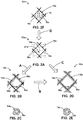
- FIG. 2B is a schematic and conceptual illustration of a region of example tubular frame 12a of FIG. 2A in which at least one defect of plurality of defects 20a is opened into a ragged window 20b.
- FIG. 2C is a schematic and conceptual illustration of a cross-section of example strut 16a of example tubular frame 12a of FIG. 2B having a ragged tissue coating, formed by a tissue layer 14b.
- tissue layer 14a in response to a force or pressure applied through tubular frame 12a or otherwise on tissue layer 14a, tissue layer 14a may deform into tissue layer 14b (as represented by arrow A) defining a different shape than tissue layer 14a, for example as shown in FIGS. 2B and 2C .
- ragged window 20b may be defined by adjacent portions of tissue layer 14b deformed by movement of corresponding flaps or portions of tissue layer 14a in response to the force or pressure.
- material of tissue layer 14a may flow, migrate, or otherwise transport in vicinity of respective defects of plurality of defects 20a to eventually form tissue layer 14b defining ragged window 20b.
- Ragged window 20b may eventually transform to a smooth window, for example, as described with reference to FIG. 2D .
- FIG. 2D is a schematic and conceptual illustration of a region of example tubular frame 12a of FIG. 2A in which at least one defect of plurality of defects 20a is opened into a smooth window 20c.
- FIG. 2E is a schematic and conceptual illustration of a cross-section of example strut 16a of example tubular frame 12 of FIG. 2D , having a smooth tissue coating formed by a tissue layer 14c.
- tissue layer 14b in response to a force or pressure applied through tubular frame 12a or otherwise on tissue layer 14b, tissue layer 14b may eventually deform into tissue layer 14c (as represented by arrow B) defining a different shape than tissue layer 14a or 14b, for example as shown in FIG. 2D and 2E .
- tissue layer 14c may define a smooth tissue coating having a substantially circular cross-section about strut 16a, as shown in FIG. 2E
- the cross-section may be ellipsoidal, polygonal, polygonal with curved corners, or any other closed cross-section.
- At least one defect of plurality of defects 20a may define a respective window in each cell of plurality of cells 18a.
- each respective window may define a polygonal edge.
- each respective window may define a curved edge.
- tissue layers 14b and 14c described with reference to FIG. 2C to 2E may be formed from tissue layer 14a described with reference to FIG. 2A
- tissue layers 14a, 14b, or 14c may be formed from a precursor tissue layer, as described with reference to FIG. 2F .
- FIG. 2F is a schematic and conceptual illustration of a region of example tubular frame 12a of FIG. 1B including struts 16a defining polygonal cells 18a coated with a precursor tissue layer 14c generated by biological cells 19.
- precursor tissue layer 14c may define substantially none or no defects.
- Defects may be introduced into precursor tissue layer 14c, for example, by cutting with an energy beam or a mechanical cutter, as described herein, to define at least one slit, or at least one window or opening.
- at least one slit may be cut into tissue layer 14c at respective cells of plurality of cells 18a to define respective defects of plurality of defects 20a, as shown in FIG 2A , or to define ragged windows 20b, as shown in FIG.
- ragged or smooth windows 20b or 20c of FIGS. 2B or 2C may be directly formed from precursor tissue layer 14c.
- plurality of defects 20a may be introduced into precursor tissue layer 14c to form tissue layer 14a of FIG. 2A (as represented by arrow D).
- Biological cells 19 may include any suitable living cells capable of forming precursor tissue layer 14c.
- Biological cells 19 may include, for example, one or both of human or animal fibroblasts, smooth muscle cells, endothelial cells, epithelial cells, or cells derived from stem cells.
- Biological cells 19 may be derived from a patient, from an animal, or from another source, for example, genetically modified or engineered cells.
- precursor tissue layer 14c After biological cells 19 form precursor tissue layer 14c, they may be preserved in precursor tissue layer 14c and in tissue layers formed from precursor tissue layer 14c, for example, tissue layers 14a, 14b, or 14c (not shown in FIGS. 2A, 2B, and 2C ). In other examples, precursor tissue layer 14c may be decellularized to substantially remove biological cells 19, as described herein. Decellularization may form precursor tissue layer 14c and tissue layers formed from precursor tissue layer 14c, for example, tissue layers 14a, 14b, or 14c, substantially free of biological cells, as shown in FIGS. 2A to 2E .
- FIG. 3A is a schematic and conceptual illustration of an exploded view of an assembly 30 including example tubular frame 12 and an example annular mold 34.
- Tubular frame 12 may have a structure and composition that is the same as or similar to tubular frames 12, 12a, or 12b, or may include any suitable tubular frame including a plurality of struts.
- tubular frame 12 may include a sidewall defining a plurality of rigid or semi-rigid connecting elements such as lines, rods, beams, braces, strips, or sections, or other connecting elements, and corresponding openings defined by the connecting elements.
- FIG. 3B is a schematic and conceptual illustration of a top view of tubular frame 12 of FIG. 3A .
- Tubular frame 12 may have a substantially circular cross-section, as shown in FIG. 3A . However, in other examples, tubular frame 12 may have an ellipsoidal, curved, undulating, polygonal, or any suitable predetermined cross-section.
- Biomaterial scaffold 36 may include a tissue precursor that may be converted to a tissue layer, for example, by live or viable biological cells.
- the biological cells may include natural cells or genetically modified or engineered cells.
- biomaterial scaffold 36 may include one or more of natural or synthetic proteins or biocompatible polymers. Proteins may include fibrin, collagen, alginate, or any suitable protein.
- Biocompatible polymers may include polyglycolic acid, polylactic acid, or any suitable biocompatible, bioconvertible, or biodegradable polymer.
- FIG. 3C is a schematic and conceptual illustration of an assembly 30a (similar to assembly 30 of FIG. 3A ) in which tubular frame 12 is cultured in annular mold 34.
- Tubular frame 12 is introduced into annular mold 34 to be in contact with biomaterial scaffold 36.
- Biomaterial scaffold 36 may be introduced into a culture media 38.
- Culture media 38 may include a liquid or gel composition configured to promote conversion of biomaterial scaffold 36 to a tissue layer, for example, by viable or live cells, such as biological cells 19 (not shown in FIGS. 3A to 3E ).
- biological cells may be seeded in either biomaterial scaffold 36 or in culture media 38.
- Culture media 38 may include nutrients predetermined to promote activity of predetermined biological cells.
- Cutting tool 40 may include a mechanical cutting element, for example, a blade, a punch, or a die, or an energy beam, for example, laser or e-beam, capable of cutting predetermined regions of tissue layer 14 to form a plurality of defects.
- cutting tool 40 may define a major surface defining a plurality of embossing or cutting features, and the major surface of cutting tool 40 may be pressed onto corresponding regions of tissue layer 14 on tubular frame 12, for example, by moving or rolling cutting tool 40 about or around tubular frame 14, to punch, emboss, or cut tissue layer 14 with the embossing or cutting features, to define the plurality of defects in tissue layer 14.
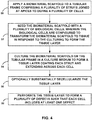
- FIG. 4 is a flowchart illustrating an example technique for forming an example tissue-coated tubular frame.
- the example technique of FIG. 4 is described with reference to example articles of FIGS. 1A to 1C and 2A to 2F , and with reference to example assemblies and systems of FIGS. 3A to 3E , for conciseness and convenience.
- the example technique of FIG. 4 may be implemented using any suitable assemblies or systems to form any suitable example articles according to the disclosure.
- the tissue precursor composition may be biomaterial scaffold 36 itself, or may be a different composition that is transformed into biomaterial scaffold 36, for example, by chemical or thermodynamic processes, for example, change in physical or chemical state.
- tubular frame 12 may be immersed in biomaterial scaffold 36 in annular mold 34, as described with reference to FIGS. 3A to 3E
- biomaterial scaffold 36 may be contained in any suitable container, and tubular frame 12 may be introduced or immersed in biomaterial scaffold 36.
- no container may be used, and biomaterial scaffold 36 may be directly applied to tubular frame 12 by an applicator, for example, a brush, a spray, or a coater.
- the example technique includes, before culturing biomaterial scaffold 36, seeding biomaterial scaffold 36 with plurality of biological cells 19 (52).
- Biological cells are configured to transform biomaterial scaffold 36 to tissue (for example, biological tissue in response to the culturing to form tissue layer 14.
- the transformation of biomaterial scaffold 36 to tissue layer 14 may include one or more of chemical cross-linking, formation and alteration of chemical bonds, or biological changes to a composition of biomaterial scaffold 36, for example, by action of biological cells 19.
- Biological cells 19 may include, for example, one or both of fibroblasts or smooth muscle cells.
- the example technique includes culturing biomaterial scaffold 36 on tubular frame 12 in culture medium 38 to form tissue layer 14 coating each strut of plurality of struts 16 and extending across each cell of plurality of cells 18 (54).
- biological cells 19 may be introduced in culture medium 38, for example, during or before the culturing 54.
- the culturing (54) includes one or more of spraying, coating, brushing, or immersing biomaterial scaffold 36 with culture medium 38.
- the culturing (54) may be performed in a batch process or in a static volume of culture medium, or in a continuous process or a flowing volume of culture medium 38, for example, in a bioreactor.
Landscapes
- Health & Medical Sciences (AREA)
- Life Sciences & Earth Sciences (AREA)
- Veterinary Medicine (AREA)
- Public Health (AREA)
- General Health & Medical Sciences (AREA)
- Animal Behavior & Ethology (AREA)
- Epidemiology (AREA)
- Vascular Medicine (AREA)
- Heart & Thoracic Surgery (AREA)
- Surgery (AREA)
- Chemical & Material Sciences (AREA)
- Medicinal Chemistry (AREA)
- Transplantation (AREA)
- Oral & Maxillofacial Surgery (AREA)
- Engineering & Computer Science (AREA)
- Biomedical Technology (AREA)
- Dermatology (AREA)
- Dispersion Chemistry (AREA)
- Molecular Biology (AREA)
- Physics & Mathematics (AREA)
- Optics & Photonics (AREA)
- Cardiology (AREA)
- Chemical Kinetics & Catalysis (AREA)
- Polymers & Plastics (AREA)
- Organic Chemistry (AREA)
- Materials For Medical Uses (AREA)
- Apparatus Associated With Microorganisms And Enzymes (AREA)
- Prostheses (AREA)
Abstract
Description
- The present disclosure relates to, in some examples, articles coated with biological tissue, in particular, medical articles coated with tissue, and techniques for coating articles with tissue.
- A functional endothelium may prevent thrombosis and maintain homeostasis of blood vessels. Disruption of the endothelium or endothelial dysfunction may lead to initiation of the coagulation cascade and thrombosis. Medical articles, for example, stents, may be introduced into the vasculature to keep vessels open. One or more surfaces of such medical articles, for example, bare metal surfaces, introduced into vasculature or other vessels may contact and apply pressure on the endothelium or other tissue.
- Medical articles coated with tissue may relatively rapidly reendothelialize after introduction into vessels and provide a relatively more biocompatible surface, potentially reducing or preventing rethrombosis or other effects or conditions.
- In some examples, the disclosure describes an example article including a tubular frame extending along a longitudinal axis. The tubular frame includes a plurality of struts joined at apices to define a plurality of cells. Each cell of the plurality of cells includes a group of struts of the plurality of struts. The example article includes a tissue layer coating each strut of the plurality of struts and extending across each cell of the plurality of cells. The tissue layer defines a plurality of defects. Each cell of the plurality of cells includes a respective defect of the plurality of defects.
- In some examples, the disclosure describes an example technique including applying a biomaterial scaffold to a tubular frame. The tubular frame includes a plurality of struts joined at apices to define a plurality of cells. The example technique includes culturing the biomaterial scaffold on the tubular frame in a culture medium to form a tissue layer. The tissue layer coats each strut of the plurality of struts and extends across each cell of the plurality of cells. The example technique includes perforating the tissue layer to form a plurality of defects such that each cell of the plurality of cells includes at least one defect of the plurality of defects.
- Clause 1: An article comprising: a tubular frame extending along a longitudinal axis, the tubular frame comprising: a plurality of struts joined at apices to define a plurality of cells, each cell of the plurality of cells comprising a group of struts of the plurality of struts; and a tissue layer coating each strut of the plurality of struts and extending across each cell of the plurality of cells, the tissue layer defining a plurality of defects, each cell of the plurality of cells including a respective defect of the plurality of defects.
- Clause 2: The article of
clause 1, wherein at least one defect of the plurality of defects includes at least one slit or at least one opening. - Clause 3: The article of clause 2, wherein the at least one slit or at least one opening is configured to expand in response to an expansion of the tubular frame to define a respective window.
- Clause 4: The article of any of
clauses 1 to 3, wherein at least one defect of the plurality of defects defines a respective window in each cell of the plurality of cells. - Clause 5: The article of clause 4, wherein each respective window defines a polygonal edge.
- Clause 6: The article of clause 4, wherein each respective window defines a curved edge.
- Clause 7: The article of any of
clauses 1 to 6, wherein the plurality of cells is configured to: collapse to compress the tubular frame into a compressed state, wherein each defect of the plurality of defects is substantially closed in the compressed state; and expand to expand the tubular frame into an expanded state, wherein each defect of the plurality of defects is substantially open in the expanded state. - Clause 8: The article of any of
clauses 1 to 7, wherein the tissue layer is substantially free of live cells. - Clause 9: The article of any of
clauses 1 to 9, wherein the tissue layer comprises extracellular matrix. - Clause 10: A method comprising: applying a biomaterial scaffold to a tubular frame comprising a plurality of struts joined at apices to define a plurality of cells; culturing the biomaterial scaffold on the tubular frame in a culture medium to form a tissue layer coating each strut of the plurality of struts and extending across each cell of the plurality of cells; and perforating the tissue layer to form a plurality of defects such that each cell of the plurality of cells includes at least one defect of the plurality of defects.
- Clause 11: The method of
clause 10, wherein the biomaterial scaffold comprises one or more of fibrin, collagen, alginate, polyglycolic acid, or polylactic acid. - Clause 12: The method of
clause 10 or clause 11, further comprising, before the culturing, seeding the biomaterial scaffold with a plurality of biological cells, wherein the biological cells are configured to transform the biomaterial scaffold to tissue in response to the culturing to form the tissue layer. - Clause 13: The method of
clause 12, wherein the biological cells comprise one or more of fibroblasts, smooth muscle cells, endothelial cells, epithelial cells, or cells derived from stem cells. - Clause 14: The method of
clause 12 or clause 13, further comprising, after the culturing, substantially decellularizing the tissue layer. - Clause 15: The method of any of
clauses 10 to 14, wherein the applying the biomaterial scaffold comprises one or more of spraying, coating, brushing, or immersing the tubular frame with a tissue precursor composition. - Clause 16: The method of any of
clauses 10 to 15, wherein the applying the biomaterial scaffold comprises immersing the tubular frame in an annular mold comprising the tissue precursor composition. - Clause 17: The method of any of
clauses 10 to 16, wherein the culturing comprises one or more of spraying, coating, brushing, or immersing the biomaterial scaffold with the culture medium. - Clause 18: The method of any of
clauses 10 to 17, wherein the perforating comprises focusing an energy beam at predetermined locations along the tissue layer for predetermined periods of time. - Clause 19: The method of any of
clauses 10 to 18, wherein the perforating comprises cutting the plurality of openings at predetermined locations along the tissue layer with a cutting tool. - Clause 20: The method of any of
clauses 10 to 19, wherein the tissue layer comprises extracellular matrix. - The details of one or more aspects of the disclosure are set forth in the accompanying drawings and the description below. Other features, objects, and advantages of the techniques described in this disclosure will be apparent from the description and drawings, and from the claims.
- Reference is made to the attached drawings, wherein elements having the same reference numeral designations represent similar elements throughout and wherein:
-
FIG. 1A is a schematic and conceptual illustration of an example article including a tubular frame including struts defining cells coated with a tissue layer defining defects. -
FIG. 1B is a schematic and conceptual illustration of a region of an example tubular frame including struts defining polygonal cells. -
FIG. 1C is a schematic and conceptual illustration of a region of an example tubular frame including struts defining polygonal cells. -
FIG. 2A is a schematic and conceptual illustration of a region of the example tubular frame ofFIG. 1B , coated with a tissue layer defining a plurality of defects. -
FIG. 2B is a schematic and conceptual illustration of a region of the example tubular frame ofFIG. 2A in which at least one defect of the plurality of defects is opened into a ragged window. -
FIG. 2C is a schematic and conceptual illustration of a cross-section of an example strut of the example tubular frame ofFIG. 2B having a ragged tissue coating formed by a tissue layer. -
FIG. 2D is a schematic and conceptual illustration of a region of the example tubular frame ofFIG. 2A in which at least one defect of the plurality of defects is opened into a smooth window. -
FIG. 2E is a schematic and conceptual illustration of a cross-section of an example strut of the example tubular frame ofFIG. 2D having a smooth tissue coating formed by a tissue layer. -
FIG. 2F is a schematic and conceptual illustration of a region of the example tubular frame ofFIG. 1B including struts defining polygonal cells coated with a precursor tissue layer generated by biological cells. -
FIG. 3A is a schematic and conceptual illustration of an exploded view of assembly including an example tubular frame and an example annular mold. -
FIG. 3B is a schematic and conceptual illustration of a top view of the tubular frame ofFIG. 3A . -
FIG. 3C is a schematic and conceptual illustration of the assembly ofFIG. 3A in which the tubular frame is cultured in the annular mold. -
FIG. 3D is a schematic and conceptual illustration of the assembly ofFIG. 3C after culturing in which the tubular frame coated with a tissue layer is removed from the annular mold. -
FIG. 3E is a schematic and conceptual illustration of a top view of the tubular frame ofFIG. 3D coated with the tissue layer. -
FIG. 4 is a flowchart illustrating an example technique for forming an example tissue-coated tubular frame. - The details of one or more aspects of the disclosure are set forth in the accompanying drawings and the description below. Other features, objects, and advantages of the techniques described in this disclosure will be apparent from the description and drawings, and from the claims.
- Implantable medical articles may reendothelialize after implantation to different extents. Medical articles, for example, stents, coated with extracellular matrix may reendothelialize more quickly that bare-metal stents, leading to lower restenosis rates. In some examples, a tissue-engineered stent may be formed by embedding a nitinol stent within a biomaterial scaffold containing biological cells, for example, fibroblasts and/or smooth muscle cells. The biomaterial scaffold may be transformed by the biological cells to tissue on culturing in a culture medium, for example, for a period of 2-4 weeks. After the conversion of the biomaterial to tissue is complete, the tissue-coated stent may be decellularized to remove substantially all biological cells or to leave substantially all biological cells dead or otherwise non-viable. In some examples, defects, for example, cuts, slits, openings, or windows, may be introduced in tissue-coated articles, allowing the tissue to contract and expand without being detached or separated from the articles. In some examples, the tissue may contract about struts of the stent due to cell-mediated forces and remodeling of tissue. In some examples, the tissue may contract or expand in response to mechanical forces exerted on the tissue.
-
FIG. 1A is a schematic and conceptual illustration of anexample article 10 including atubular frame 12 coated with atissue layer 14.Tubular frame 12 may have a circular, oval, ellipsoidal, curved, undulating, polygonal, or any suitable predetermined cross-section. In some examples,tubular frame 12 defines an implantable medical device, for example, a stent, a shunt, or a tube.Tubular frame 12 extends along a longitudinal axis defined by respective ends oftubular frame 12.Tubular frame 12 includesstruts 16 defining plurality ofcells 18.Struts 16 may include any rigid or semi-rigid material capable of maintaining a predetermined structure. For example, struts 16 may include any suitable non-degradable or biodegradable material, for example, one or more of metal, alloy, polymer, or ceramic.Struts 16 of each cell of plurality ofcells 18 may have substantially the same length and width, or may differ in one or both of length or width. In some examples, struts 16 may be porous, for example, including pores that admit biological cells, or a fluid. While tissue may form a coating or a layer, the coating or layer may be substantially integrated with, or inseparable from,tubular frame 12. - Each cell of plurality of
cells 18 may includestruts 16 arranged to maintain a predetermined shape or geometry of the respective cell in response to predetermined force or pressure applied on one or more regions oftubular frame 12. For example, each cell of plurality ofcells 18 may include a closed polygon including at least three, or at least four, or more struts 16. - For example,
FIG. 1B is a schematic and conceptual illustration of a region of anexample tubular frame 12a including struts 16a defining polygonal plurality ofcells 18a.Tubular frame 12a may be coated with a tissue layer (not shown inFIG. 1B ), for example, as described with reference toFIG. 2A . In some examples, each cell of plurality ofcells 18a may includestruts 16a connected atrespective apices 15a defining a polygon, for example, a rectangular polygon. In some examples, each cell of plurality ofcells 18a may include undulatingstruts 16a connected atrespective apices 15a. Whilecells 18a ofFIG. 1B include four-sided polygons, in other examples, example articles according to the disclosure may include any suitable n-sided polygons, where n is a predetermined index. The polygons may be simple, or convex polygons, or other polygons, for example, as shown inFIG. 1C . -
FIG. 1C is a schematic and conceptual illustration of a region of anexample tubular frame 12b including struts 16b definingpolygonal cells 18b.Struts 16b may be connected atapices 15b.Struts 16b may define a non-convex (or concave polygon), for example, as shown inFIG. 1C .Tubular frame 12b may be coated with a tissue layer (not shown inFIG. 1B ), for example, a tissue layer defining a plurality of defects (not shown inFIG. 1B ) according to the disclosure. - Turning back to
FIG. 1A ,tissue layer 14 may extend across substantially each cell of plurality ofcells 18, for example, all but a few of plurality ofcells 18. In some examples,tissue layer 14 extends across each cell of plurality ofcells 18. In some examples,tissue layer 14 coats substantially all struts, for example, all but a few struts, of plurality ofstruts 16. In some examples,tissue layer 14 coats each strut of plurality ofstruts 16.Tissue layer 14 may include any suitable biological tissue, for example, tissue formed or generated by biological cells, or by a biological or biotechnological process. In some examples,tissue layer 14 may include a plurality of biological or live cells. In other examples,tissue layer 14 may be substantially decellularized, or substantially free of live cells. For example, cells may be present intissue layer 14, but may be dead or otherwise non-viable cells.Decellularized tissue layer 14 may exhibit a reduced immune response or allergenicity compared totissue layer 14 including cells. The tissue may be formed from a suitable precursor material. In some examples,tissue layer 14 includes extracellular matrix, or a variant, derivative, or analog of extracellular matrix. The extracellular matrix or analog may include one or more of collagen, fibronectin, laminin, glycosaminoglycans, or other components, for example, growth factors and cytokines. In some examples, the tissue may be formed by biological cells that convert the precursor material, for example, proteinaceous material including, but not limited to, fibrin, collagen, or alginate, or polymeric material including, but not limited to, PGA, PLA, or other biodegradable or biocompatible polymers.Tissue layer 14 may providetubular frame 12 with a biocompatible surface. For example,tubular frame 12 includingtissue layer 14 may reendothelialize more quickly compared to that of baretubular frame 12 ortubular frame 12 otherwise withouttissue layer 14. - In some examples,
tissue layer 18 is discontinuous. For example,tissue layer 18 may define a plurality ofdefects 20, as shown inFIG. 1A . One or more defects of plurality ofdefects 20 may define a discontinuity, for example, a void, a gap, a window, an opening, a slit, or any predetermined discontinuity, intissue layer 18. In some examples, substantially all cells, for example, all but a few cells, of plurality ofcells 14 includes at least one defect of plurality ofdefects 20. In some examples, each cell of plurality ofcells 14 includes a respective defect of plurality ofdefects 20. In some examples, one or more cells of plurality ofcells 14 may include more than one defect of plurality ofdefects 20. - Plurality of
defects 20 may allow one or more portions oftissue layer 14 to deform, for example, by sliding across or along a respective cell of plurality ofcells 18a oftubular frame 12. The deformation oftissue layer 14 may allowtissue layer 14 to be retained on tubular frame 12 (for example, remain attached to or on tubular frame 12) even iftubular frame 12 changes shape or configuration. For example, a tissue layer that does not include defects may break or rupture in an uncontrolled manner, which may cause one or more portions of the tissue layer to separate from respective regions oftubular frame 12, leaving one or more cells of plurality ofcells 18 without tissue layer, or leaving one or more struts of plurality ofstruts 16 without a coating of tissue layer. Such uncoated or uncovered portions oftubular frame 12 may expose bare material of plurality ofstruts 16 to a body lumen. In contrast,tissue layer 14 defining plurality ofdefects 20 may be substantially retained on plurality ofstruts 16a and ontubular frame 12 even whentubular frame 12 expands or contracts. For example, plurality ofdefects 20 may allow predetermined portions oftissue layer 14 to relax or deform within a predetermined tolerance in response to application of force or pressure ontubular frame 12, such that the force or pressure does not push, squeeze, or otherwise causetissue layer 14 to be removed (for example, detached), fromtubular frame 12. Thus, a bare material or exposed material oftubular frame 12 coated withtissue layer 14 that includes plurality ofdefects 20 may not be exposed to a body lumen in whichtubular frame 12 is introduced, even in response to a force or pressure tending to change a configuration oftubular frame 12. - Thus, in some examples, plurality of
cells 18 is configured to collapse to compresstubular frame 12 into a compressed state, where each defect of plurality ofdefects 20 is substantially closed in the compressed state. Instead, or in addition, plurality ofcells 18 may be configured to expand to expandtubular frame 12 into an expanded state, where each defect of plurality ofdefects 20 is substantially open in the expanded state. In some examples, in the compressed state,tubular frame 12 may have an average diameter or cross-sectional dimension that is smaller than a corresponding average diameter or cross-sectional dimension in the expanded state. In some examples, in the compressed state,tubular frame 12 may have a length that is smaller than a corresponding length in the expanded state. In some examples, the compressed state of tubular frame may be associated with an undeployed configuration oftubular frame 12, for example, prior to implantation, or during transport to an implantation site. In some examples, the expanded state oftubular frame 12 may be associated with a deployed configuration oftubular frame 12, for example, when implanted at an implantation site. - While plurality of
defects 20 may include one or more polygonal defects, for example, substantially rectangular defects, as shown inFIG. 1A , in other examples, plurality ofdefects 20 may include one or more defects having other shapes. For example, one or more defects of plurality ofdefects 20 may define at least one opening or at least one window intissue layer 14, for example, an opening having a triangular, square, parallelepiped, rhomboidal, or n-sided polygonal shaped periphery, where n may be at least 3, or circular, ellipsoidal, curved, or any suitable closed opening. In some examples, the window may not be open, and may instead define a portion oftissue layer 14 that has a reduced thickness compared to other portions oftissue layer 14. In some examples, windows defining portions of reduced thickness may open in response to an applied force or pressure, generating respective openings intissue layer 14. In some examples, one or more defects of plurality ofdefects 20 may define at least one slit that may open in response to applied forces or pressures. For example, the at least one slit or at least one opening may be configured to expand in response to an expansion oftubular frame 12 to define a respective window. For example, the at least one slit may expand along a direction transverse to a longitudinal axis or a major axis defined by the at least one slit. Instead of, or in addition to, transverse expansion, in some examples, the at least one slit may contract along a direction alone the longitudinal axis or the major axis defined by the at least one slit. - Plurality of
defects 20 may include defects having substantially the same size or shape, or defects having different sizes or shapes. In some examples, substantially each cell of plurality ofcells 18 defines the same or similar defects. In other examples, different groups of cells of plurality ofcells 18 may define different defect geometries. Thus, respective defects of plurality ofdefects 20 may be distributed along respective cells of plurality of cells in any suitable predetermined pattern, for example, a pattern that allows portions oftissue layer 14 to deform in response to forces or pressures while substantially retainingtissue layer 14 ontubular frame 12. In some examples, one or more defects of plurality ofdefects 20 may change shape or size in response to deformations oftubular frame 12, for example, as described with reference toFIGS. 2A to 2F . -
FIG. 2A is a schematic and conceptual illustration of a region of exampletubular frame 12a ofFIG. 1B , coated withtissue layer 14a defining plurality ofdefects 20a. Plurality ofdefects 20a includes at least oneslit 21a, as shown inFIG. 2A . The slit may be defined by edges oftissue layer 14a substantially in contact with each other, for example, a closed slit, or edges oftissue layer 14a having a predetermined separation respect to each other, for example, a separation of at least 0.01 millimeter (mm), or at least 0.1 mm, or at least 1 mm, for example, an open slit. The at least one slit may deform to define an opening in response to an applied force or pressure, for example, deforming from slits to openings, as described with reference toFIGS. 2B to 2E . In some examples, the at least one slit of plurality ofdefects 20a may only temporary deform into an opening in response to a first force or pressure ontubular frame 12a, for example, by movement of flaps adjacent the at least one slit, and be restored to its initial slit form, in response to a second force or pressure ontubular frame 12a. -
FIG. 2B is a schematic and conceptual illustration of a region of exampletubular frame 12a ofFIG. 2A in which at least one defect of plurality ofdefects 20a is opened into aragged window 20b.FIG. 2C is a schematic and conceptual illustration of a cross-section ofexample strut 16a of exampletubular frame 12a ofFIG. 2B having a ragged tissue coating, formed by atissue layer 14b. In some examples, in response to a force or pressure applied throughtubular frame 12a or otherwise ontissue layer 14a,tissue layer 14a may deform intotissue layer 14b (as represented by arrow A) defining a different shape thantissue layer 14a, for example as shown inFIGS. 2B and 2C . For example,ragged window 20b may be defined by adjacent portions oftissue layer 14b deformed by movement of corresponding flaps or portions oftissue layer 14a in response to the force or pressure. For example, material oftissue layer 14a may flow, migrate, or otherwise transport in vicinity of respective defects of plurality ofdefects 20a to eventually formtissue layer 14b definingragged window 20b.Ragged window 20b may eventually transform to a smooth window, for example, as described with reference toFIG. 2D . -
FIG. 2D is a schematic and conceptual illustration of a region of exampletubular frame 12a ofFIG. 2A in which at least one defect of plurality ofdefects 20a is opened into asmooth window 20c.FIG. 2E is a schematic and conceptual illustration of a cross-section ofexample strut 16a of exampletubular frame 12 ofFIG. 2D , having a smooth tissue coating formed by atissue layer 14c. In some examples, in response to a force or pressure applied throughtubular frame 12a or otherwise ontissue layer 14b,tissue layer 14b may eventually deform intotissue layer 14c (as represented by arrow B) defining a different shape thantissue layer FIG. 2D and 2E . For example,ragged window 20b may transform intosmooth window 20c by movement of corresponding flaps or portions oftissue layer 14b in response to the force or pressure. For example, material oftissue layer 14b may flow, migrate, or otherwise transport in vicinity ofragged window 20b to eventually formtissue layer 14c definingsmooth window 20c. In some examples,tissue layer 14a defining at least one slit in plurality ofdefects 20a may deform intotissue layer 14c (as represented by arrow C) defining at least onesmooth window 20c, as represented by the arrow betweenFIGS. 2A and 2D , for example, by flow, migration, or transport of material in vicinity of plurality ofdefects 20a to eventually formsmooth window 20c. Whiletissue layer 14c may define a smooth tissue coating having a substantially circular cross-section aboutstrut 16a, as shown inFIG. 2E , in other examples, the cross-section may be ellipsoidal, polygonal, polygonal with curved corners, or any other closed cross-section. - Thus, in some examples, at least one defect of plurality of
defects 20a may define a respective window in each cell of plurality ofcells 18a. In some examples, each respective window may define a polygonal edge. In some examples, each respective window may define a curved edge. - While the configurations of tissue layers 14b and 14c described with reference to
FIG. 2C to 2E may be formed fromtissue layer 14a described with reference toFIG. 2A , one or more oftissue layers FIG. 2F . -
FIG. 2F is a schematic and conceptual illustration of a region of exampletubular frame 12a ofFIG. 1B including struts 16a definingpolygonal cells 18a coated with aprecursor tissue layer 14c generated bybiological cells 19. As shown inFIG. 2F ,precursor tissue layer 14c may define substantially none or no defects. Defects may be introduced intoprecursor tissue layer 14c, for example, by cutting with an energy beam or a mechanical cutter, as described herein, to define at least one slit, or at least one window or opening. For example, at least one slit may be cut intotissue layer 14c at respective cells of plurality ofcells 18a to define respective defects of plurality ofdefects 20a, as shown inFIG 2A , or to defineragged windows 20b, as shown inFIG. 2B , or to define smooth windows, as shown inFIG. 2C . Thus, in some examples, ragged orsmooth windows FIGS. 2B or 2C may be directly formed fromprecursor tissue layer 14c. Similarly, plurality ofdefects 20a may be introduced intoprecursor tissue layer 14c to formtissue layer 14a ofFIG. 2A (as represented by arrow D). -
Biological cells 19 may include any suitable living cells capable of formingprecursor tissue layer 14c.Biological cells 19 may include, for example, one or both of human or animal fibroblasts, smooth muscle cells, endothelial cells, epithelial cells, or cells derived from stem cells.Biological cells 19 may be derived from a patient, from an animal, or from another source, for example, genetically modified or engineered cells. In some examples,biological cells 19 may include one or more of fibroblasts, smooth muscle cells, endothelial cells, epithelial cells, mesenchymal stem cells, bone marrow-derived stem cells, adipose-derived stem cells, hair follicle-derived stem cells, autologous amniotic fluid cells, pluripotent stem cells, pluripotent stem cell-derived progenitor cells, or cells derived from one or more of these cells. In some examples,biological cells 19 may formprecursor tissue layer 14c from a biomaterial scaffold, as described herein. Afterbiological cells 19 formprecursor tissue layer 14c, they may be preserved inprecursor tissue layer 14c and in tissue layers formed fromprecursor tissue layer 14c, for example,tissue layers FIGS. 2A, 2B, and 2C ). In other examples,precursor tissue layer 14c may be decellularized to substantially removebiological cells 19, as described herein. Decellularization may formprecursor tissue layer 14c and tissue layers formed fromprecursor tissue layer 14c, for example,tissue layers FIGS. 2A to 2E . - While the example articles of
FIGS. 2A to 2F are described with reference totubular frame 12a ofFIG. 1B , example articles according to the disclosure may include any suitable tubular frame according to the disclosure, for example,tubular frame 12 ofFIG. 1A ,tubular frame 12b ofFIG. 1C . Thus, tissue layers 14, 14a, 14b, or 14c, or other tissue layers according to the disclosure may be formed ontubular frames - Example articles according to the disclosure may be formed using any suitable systems, assemblies, and techniques, for example, example assemblies and systems described with reference to
FIGS. 3A to 3E and example techniques described with reference toFIG. 4 . -
FIG. 3A is a schematic and conceptual illustration of an exploded view of an assembly 30 includingexample tubular frame 12 and an exampleannular mold 34.Tubular frame 12 may have a structure and composition that is the same as or similar totubular frames tubular frame 12 may include a sidewall defining a plurality of rigid or semi-rigid connecting elements such as lines, rods, beams, braces, strips, or sections, or other connecting elements, and corresponding openings defined by the connecting elements.FIG. 3B is a schematic and conceptual illustration of a top view oftubular frame 12 ofFIG. 3A .Tubular frame 12 may have a substantially circular cross-section, as shown inFIG. 3A . However, in other examples,tubular frame 12 may have an ellipsoidal, curved, undulating, polygonal, or any suitable predetermined cross-section. - Bare
tubular frame 12 may initially not have any tissue layer, as shown inFIGS. 3A and 3B . A tissue layer may be formed ontubular frame 12 from abiomaterial scaffold 36 applied to or in contact withtubular frame 12.Biomaterial scaffold 36 may include a tissue precursor that may be converted to a tissue layer, for example, by live or viable biological cells. The biological cells may include natural cells or genetically modified or engineered cells. In some examples,biomaterial scaffold 36 may include one or more of natural or synthetic proteins or biocompatible polymers. Proteins may include fibrin, collagen, alginate, or any suitable protein. Biocompatible polymers may include polyglycolic acid, polylactic acid, or any suitable biocompatible, bioconvertible, or biodegradable polymer. In some examples,biomaterial scaffold 36 includes one or more of fibrin, collagen, alginate, chitin, gelatin, polyglycolic acid, or polylactic acid. In some examples,biomaterial scaffold 36 may include hydrolytically degradable polymers, poly (a-esters), polyglycolide, polylactides, poly(lactide-co-glycolide), polydioxanone, polycaprolactone, poly(trimethylene carbonate) bacterial polyesters, polyurethanes, poly(ester amide), poly(ortho esters), polyanhydrides, poly(anhydride-co-imide), cross-linked polyanhydrides, poly(propylene fumarate), pseudo poly(amino acid), poly(alkyl cyanoacrylates), polyphosphazenes, polyphosphoester, enzymatically degradable polymers, proteins and poly(amino acids), collagen, elastin, elastin-like peptides, albumin, fibrin, or polysaccharides, or any suitable biodegradable polymers described in the article titled "Biodegradable polymers as biomaterials" (Progress in Polymer Science, 32 (2007) 762-798) by Nair et al., incorporated herein in its entirety by reference.Biomaterial scaffold 36 may include a liquid, gel, emulsion, colloid, semi-solid, or solid composition. In some examples, the state ofbiomaterial scaffold 36 may change from one of liquid, gel, emulsion, colloid, semi-solid, or solid to another of liquid, gel, emulsion, colloid, semi-solid, or solid in response to predetermined changes in temperature, pH, cellular activity, or other predetermined conditions before, during, or after applyingbiological scaffold 36 totubular frame 12. In some examples,annular mold 34 may containtissue precursor 36, and tubular frame may be introduced intobiomaterial scaffold 36 inannular mold 34, as described with reference toFIG. 3C . -
FIG. 3C is a schematic and conceptual illustration of anassembly 30a (similar to assembly 30 ofFIG. 3A ) in whichtubular frame 12 is cultured inannular mold 34.Tubular frame 12 is introduced intoannular mold 34 to be in contact withbiomaterial scaffold 36.Biomaterial scaffold 36 may be introduced into aculture media 38.Culture media 38 may include a liquid or gel composition configured to promote conversion ofbiomaterial scaffold 36 to a tissue layer, for example, by viable or live cells, such as biological cells 19 (not shown inFIGS. 3A to 3E ). For example, biological cells may be seeded in eitherbiomaterial scaffold 36 or inculture media 38.Culture media 38 may include nutrients predetermined to promote activity of predetermined biological cells.Biomaterial scaffold 36 may be maintained inculture media 38 under predetermined conditions, for example, temperature, pH, nutrient composition, and time, so that biological cells may eventually convert at least a portion ofbiomaterial scaffold 36 to form a tissue layer. After the culturing, tubular frame 30 may be removed fromannular mold 34, as described with reference toFIG. 3D . -
FIG. 3D is a schematic and conceptual illustration of anassembly 30b (similar toassembly 30a ofFIG. 3C ) after culturing in whichtubular frame 12 coated withtissue layer 14 is removed fromannular mold 34.FIG. 3E is a schematic and conceptual illustration of a top view of the tubular frame ofFIG. 3D coated with the tissue layer.Tissue layer 14 may be the same as or similar toprecursor tissue layer 14c described with reference toFIG. 2F , or any other tissue layer according to the disclosure. In some examples,tissue layer 14 may initially be substantially continuous, and may be cut usingcutting tool 40 to generate a plurality of defects intissue layer 14, for example, any suitable plurality of defects as described in the disclosure. Cuttingtool 40 may include a mechanical cutting element, for example, a blade, a punch, or a die, or an energy beam, for example, laser or e-beam, capable of cutting predetermined regions oftissue layer 14 to form a plurality of defects. In some examples, cuttingtool 40 may define a major surface defining a plurality of embossing or cutting features, and the major surface of cuttingtool 40 may be pressed onto corresponding regions oftissue layer 14 ontubular frame 12, for example, by moving or rollingcutting tool 40 about or aroundtubular frame 14, to punch, emboss, or cuttissue layer 14 with the embossing or cutting features, to define the plurality of defects intissue layer 14. - Thus, example assemblies and systems according to the disclosure may be used to form example articles including example tissue layers defining a plurality of defects on example tubular frames.
-
FIG. 4 is a flowchart illustrating an example technique for forming an example tissue-coated tubular frame. The example technique ofFIG. 4 is described with reference to example articles ofFIGS. 1A to 1C and2A to 2F , and with reference to example assemblies and systems ofFIGS. 3A to 3E , for conciseness and convenience. However, the example technique ofFIG. 4 may be implemented using any suitable assemblies or systems to form any suitable example articles according to the disclosure. - In some examples, the example technique of
FIG. 4 includes applyingbiomaterial scaffold 36 totubular frame 12 including plurality ofstruts 16 joined at apices 15 to define plurality of cells 18 (50). In some examples,biomaterial scaffold 36 includes one or more of fibrin, collagen, alginate, polyglycolic acid, or polylactic acid. Applyingbiomaterial scaffold 36 may include one or more of spraying, coating, brushing, or immersingtubular frame 12 with a tissue precursor composition. In some examples, applying biomaterial scaffold 36 (50) includes immersingtubular frame 12 inannular mold 34 including the tissue precursor composition. - The tissue precursor composition may be
biomaterial scaffold 36 itself, or may be a different composition that is transformed intobiomaterial scaffold 36, for example, by chemical or thermodynamic processes, for example, change in physical or chemical state. Whiletubular frame 12 may be immersed inbiomaterial scaffold 36 inannular mold 34, as described with reference toFIGS. 3A to 3E , in other examples,biomaterial scaffold 36 may be contained in any suitable container, andtubular frame 12 may be introduced or immersed inbiomaterial scaffold 36. In some examples, no container may be used, andbiomaterial scaffold 36 may be directly applied totubular frame 12 by an applicator, for example, a brush, a spray, or a coater. - In some examples, the example technique includes, before culturing
biomaterial scaffold 36, seedingbiomaterial scaffold 36 with plurality of biological cells 19 (52). Biological cells are configured to transformbiomaterial scaffold 36 to tissue (for example, biological tissue in response to the culturing to formtissue layer 14. The transformation ofbiomaterial scaffold 36 totissue layer 14 may include one or more of chemical cross-linking, formation and alteration of chemical bonds, or biological changes to a composition ofbiomaterial scaffold 36, for example, by action ofbiological cells 19.Biological cells 19 may include, for example, one or both of fibroblasts or smooth muscle cells. - The example technique includes culturing
biomaterial scaffold 36 ontubular frame 12 inculture medium 38 to formtissue layer 14 coating each strut of plurality ofstruts 16 and extending across each cell of plurality of cells 18 (54). In some examples, instead of, or in addition to, seedingbiomaterial scaffold 36 withbiological cells 19,biological cells 19 may be introduced inculture medium 38, for example, during or before theculturing 54. In some examples, the culturing (54) includes one or more of spraying, coating, brushing, or immersingbiomaterial scaffold 36 withculture medium 38. The culturing (54) may be performed in a batch process or in a static volume of culture medium, or in a continuous process or a flowing volume ofculture medium 38, for example, in a bioreactor. - In some examples, the example technique further includes, after the culturing (54), substantially decellularizing tissue layer 14 (56). The decellularizing (56) may include any suitable treatment that may one or more of reduce or prevent the growth or activity of
biological cells 19, killbiological cells 19, or removebiological cells 19 fromtissue layer 14, for example, trypsin-EDTA treatment, washing with detergent, washing with EDTA solution, freezing, dehydration, depressurizing, vacuum, radiation, or lyophilization. In some examples, after the decellularizing (56), less than 50%, or less than 75%, or less than 90%, or less than 95% of an initial population ofbiological cells 19 may remain viable, or may remain physically withintissue layer 14. - The example technique may include perforating
tissue layer 14 to form plurality ofdefects 20 such that each cell of plurality ofcells 18 includes at least one defect of plurality of defects 20 (58). In examples in which the example technique includes both the decellularizing (56) and the perforating (58), the perforating (58) may be performed before or after the decellularizing (56). In some examples, the perforating (58) includes focusing an energy beam, for example, from a laser source or an e-beam source, at predetermined locations alongtissue layer 14 for predetermined periods of time. In some examples, the perforating (58) includes cutting a plurality of openings at predetermined locations alongtissue layer 14 with cuttingtool 40. - Various examples have been described. These and other examples are within the scope of the following claims.
Claims (15)
- An article comprising:
a tubular frame extending along a longitudinal axis, the tubular frame comprising:a plurality of struts joined at apices to define a plurality of cells, each cell of the plurality of cells comprising a group of struts of the plurality of struts; anda tissue layer coating each strut of the plurality of struts and extending across each cell of the plurality of cells, the tissue layer defining a plurality of defects, each cell of the plurality of cells including a respective defect of the plurality of defects. - The article of claim 1, wherein at least one defect of the plurality of defects includes at least one slit or at least one opening.
- The article of claim 2, wherein the at least one slit or at least one opening is configured to expand in response to an expansion of the tubular frame to define a respective window.
- The article of any of the preceding claims, wherein at least one defect of the plurality of defects defines a respective window in each cell of the plurality of cells, wherein optionally each respective window defines a polygonal edge, or wherein each respective window defines a curved edge.
- The article of any of the preceding claims, wherein the plurality of cells is configured to:collapse to compress the tubular frame into a compressed state, wherein each defect of the plurality of defects is substantially closed in the compressed state; andexpand to expand the tubular frame into an expanded state, wherein each defect of the plurality of defects is substantially open in the expanded state.
- The article of any of the preceding claims, wherein the tissue layer is substantially free of live cells, and/or wherein the tissue layer comprises extracellular matrix.
- A method comprising:applying a biomaterial scaffold to a tubular frame comprising a plurality of struts joined at apices to define a plurality of cells;culturing the biomaterial scaffold on the tubular frame in a culture medium to form a tissue layer coating each strut of the plurality of struts and extending across each cell of the plurality of cells; andperforating the tissue layer to form a plurality of defects such that each cell of the plurality of cells includes at least one defect of the plurality of defects.
- The method of claim 7, wherein the biomaterial scaffold comprises one or more of fibrin, collagen, alginate, polyglycolic acid, or polylactic acid.
- The method of claim 7 or 8, further comprising, before the culturing, seeding the biomaterial scaffold with a plurality of biological cells, wherein the biological cells are configured to transform the biomaterial scaffold to tissue in response to the culturing to form the tissue layer.
- The method of claim 9, wherein the biological cells comprise one or more of fibroblasts, smooth muscle cells, endothelial cells, epithelial cells, or cells derived from stem cells.
- The method of any of claims 9-10, further comprising, after the culturing, substantially decellularizing the tissue layer.
- The method of any of claims 7-11, wherein the applying the biomaterial scaffold comprises one or more of spraying, coating, brushing, or immersing the tubular frame with a tissue precursor composition, and/or wherein the applying the biomaterial scaffold comprises immersing the tubular frame in an annular mold comprising the tissue precursor composition, and/or wherein the culturing comprises one or more of spraying, coating, brushing, or immersing the biomaterial scaffold with the culture medium.
- The method of any of claims 7-12, wherein the perforating comprises focusing an energy beam at predetermined locations along the tissue layer for predetermined periods of time.
- The method of any of claims 7-13, wherein the perforating comprises cutting the plurality of openings at predetermined locations along the tissue layer with a cutting tool.
- The method of any of claims 7-14, wherein the tissue layer comprises extracellular matrix.
Applications Claiming Priority (1)
| Application Number | Priority Date | Filing Date | Title |
|---|---|---|---|
| US15/927,116 US10925757B2 (en) | 2018-03-21 | 2018-03-21 | Tissue-coated articles |
Publications (2)
| Publication Number | Publication Date |
|---|---|
| EP3542832A1 true EP3542832A1 (en) | 2019-09-25 |
| EP3542832B1 EP3542832B1 (en) | 2023-05-24 |
Family
ID=65818322
Family Applications (1)
| Application Number | Title | Priority Date | Filing Date |
|---|---|---|---|
| EP19163431.0A Active EP3542832B1 (en) | 2018-03-21 | 2019-03-18 | Tissue-coated articles |
Country Status (3)
| Country | Link |
|---|---|
| US (1) | US10925757B2 (en) |
| EP (1) | EP3542832B1 (en) |
| CN (1) | CN110292664A (en) |
Citations (3)
| Publication number | Priority date | Publication date | Assignee | Title |
|---|---|---|---|---|
| EP1923025A2 (en) * | 2006-11-17 | 2008-05-21 | EV3, Inc. | Stent having reduced passage of emboli and stent delivery system |
| WO2010101780A2 (en) * | 2009-03-04 | 2010-09-10 | Peytant Solutions, Inc. | Stents modified with material comprising amnion tissue and corresponding processes |
| WO2017176919A1 (en) * | 2016-04-05 | 2017-10-12 | Regents Of The University Of Minnesota | Engineered tissues having structural components embedded therein, and methods of making and using |
Family Cites Families (25)
| Publication number | Priority date | Publication date | Assignee | Title |
|---|---|---|---|---|
| US6475232B1 (en) * | 1996-12-10 | 2002-11-05 | Purdue Research Foundation | Stent with reduced thrombogenicity |
| US6096073A (en) * | 1997-02-25 | 2000-08-01 | Scimed Life Systems, Inc. | Method of deploying a stent at a lesion site located at a bifurcation in a parent vessel |
| US7736687B2 (en) * | 2006-01-31 | 2010-06-15 | Advance Bio Prosthetic Surfaces, Ltd. | Methods of making medical devices |
| US20030009213A1 (en) | 2000-03-13 | 2003-01-09 | Jun Yang | Stent having cover with drug delivery capability |
| AU2001261200B2 (en) | 2000-05-04 | 2006-02-09 | Oregon Health Sciences University | Endovascular stent graft |
| US8038708B2 (en) * | 2001-02-05 | 2011-10-18 | Cook Medical Technologies Llc | Implantable device with remodelable material and covering material |
| US6752826B2 (en) | 2001-12-14 | 2004-06-22 | Thoratec Corporation | Layered stent-graft and methods of making the same |
| ATE377398T1 (en) | 2002-11-22 | 2007-11-15 | Cook Inc | STENT VESSEL TRANSPLANT |
| US20050013870A1 (en) | 2003-07-17 | 2005-01-20 | Toby Freyman | Decellularized extracellular matrix of conditioned body tissues and uses thereof |
| DE602005020754D1 (en) | 2004-03-31 | 2010-06-02 | Cook Inc | TRANSPLANT MATERIAL AND VASCOPY THERAPY WITH EXTRACELLULAR COLLAGEN MATRIX AND ITS MANUFACTURING PROCESS |
| US20080033522A1 (en) | 2006-08-03 | 2008-02-07 | Med Institute, Inc. | Implantable Medical Device with Particulate Coating |
| CN100475279C (en) * | 2006-12-27 | 2009-04-08 | 重庆大学 | Imaginal stem cell membrane stent in blood vessel, and preparing method thereof |
| US8172908B2 (en) * | 2008-01-17 | 2012-05-08 | The University Of Hong Kong | Implant for tissue engineering |
| WO2009117721A1 (en) | 2008-03-21 | 2009-09-24 | 3D Biotek, Llc | Hybrid biomedical device fabricated from biomaterials and coated with a cell culture derived ecm coating |
| US20100191323A1 (en) | 2009-01-23 | 2010-07-29 | Mitchell Wayne Cox | Biodegradable stent graft |
| US10232092B2 (en) | 2010-04-22 | 2019-03-19 | Micell Technologies, Inc. | Stents and other devices having extracellular matrix coating |
| EP2663256A1 (en) * | 2011-01-13 | 2013-11-20 | Innovia LLC | Endoluminal drug applicator and method of treating diseased vessels of the body |
| WO2013056049A2 (en) | 2011-10-14 | 2013-04-18 | Humacyte, Inc. | Tubular prostheses |
| CN105555327B (en) * | 2013-05-31 | 2018-10-26 | 谢尔蒂斯有限公司 | The method and composition with engineering is repaired for vascular tissue |
| AU2014370031A1 (en) * | 2013-12-27 | 2016-07-21 | Neograft Technologies, Inc. | Artificial graft devices and related systems and methods |
| CN105287048B (en) * | 2014-07-03 | 2017-06-23 | 上海理工大学 | Overlay film frame |
| WO2016030898A1 (en) * | 2014-08-27 | 2016-03-03 | Amnis Therapeutics Ltd. | Implantable devices comprising graft membranes |
| US10111741B2 (en) * | 2014-10-29 | 2018-10-30 | W. L. Gore & Associates, Inc. | Intralumenal stent graft fixation |
| CN204542984U (en) * | 2014-12-25 | 2015-08-12 | 东莞颠覆产品设计有限公司 | A kind of expansible angiocarpy bracket with collagen protein overlay film |
| WO2017004598A1 (en) * | 2015-07-02 | 2017-01-05 | Nsvascular, Inc. | Thin-film micromesh medical devices and related methods |
-
2018
- 2018-03-21 US US15/927,116 patent/US10925757B2/en active Active
-
2019
- 2019-03-13 CN CN201910188461.9A patent/CN110292664A/en active Pending
- 2019-03-18 EP EP19163431.0A patent/EP3542832B1/en active Active
Patent Citations (3)
| Publication number | Priority date | Publication date | Assignee | Title |
|---|---|---|---|---|
| EP1923025A2 (en) * | 2006-11-17 | 2008-05-21 | EV3, Inc. | Stent having reduced passage of emboli and stent delivery system |
| WO2010101780A2 (en) * | 2009-03-04 | 2010-09-10 | Peytant Solutions, Inc. | Stents modified with material comprising amnion tissue and corresponding processes |
| WO2017176919A1 (en) * | 2016-04-05 | 2017-10-12 | Regents Of The University Of Minnesota | Engineered tissues having structural components embedded therein, and methods of making and using |
Non-Patent Citations (2)
| Title |
|---|
| LIPING ZHAO ET AL: "Engineered Tissue-Stent Biocomposites as Tracheal Replacements", TISSUE ENGINEERING PART A, vol. 22, no. 17-18, 1 September 2016 (2016-09-01), US, pages 1086 - 1097, XP055612544, ISSN: 1937-3341, DOI: 10.1089/ten.tea.2016.0132 * |
| NAIR: "Biodegradable polymers as biomaterials", PROGRESS IN POLYMER SCIENCE, vol. 32, 2007, pages 762 - 798, XP022188822, DOI: doi:10.1016/j.progpolymsci.2007.05.017 |
Also Published As
| Publication number | Publication date |
|---|---|
| EP3542832B1 (en) | 2023-05-24 |
| US10925757B2 (en) | 2021-02-23 |
| CN110292664A (en) | 2019-10-01 |
| US20190290461A1 (en) | 2019-09-26 |
Similar Documents
| Publication | Publication Date | Title |
|---|---|---|
| EP1863545B1 (en) | Prosthetic implants including ECM composite material | |
| Beckstead et al. | Esophageal epithelial cell interaction with synthetic and natural scaffolds for tissue engineering | |
| L'heureux et al. | A completely biological tissue‐engineered human blood vessel | |
| US7198641B2 (en) | Scaffolds for tissue engineered hair | |
| AU2021200593A1 (en) | Adipose tissue matrices | |
| EP3678714B1 (en) | Tissue-engineered medical device | |
| Dijkman et al. | Heart valve replacements with regenerative capacity | |
| WO1993023088A1 (en) | Biotherapeutic cell-coated microspheres | |
| CA2186375A1 (en) | Improved blood contact surfaces using endothelium on a subendothelial extracellular matrix | |
| EP0989867A2 (en) | Biosynthetic transplant and method for the production thereof | |
| HRP20120591T1 (en) | PROCEDURES FOR THE PRODUCTION OF HAIR MICROFOLICULES AND NEW PAPILES AND THEIR USE FOR IN VITRO TESTING AND IN VIVO IMPLANTATION | |
| Sahakyants et al. | Tissue engineering: from the bedside to the bench and back to the bedside | |
| KR20140033057A (en) | Cell-synthesized particles | |
| WO2011071074A1 (en) | Porous member, method for causing porosity, and method for manufacturing said porous member | |
| EP3542832B1 (en) | Tissue-coated articles | |
| Copeland et al. | Decellularization in heart valve tissue engineering | |
| JP2005198825A (en) | Biological tissue formation promotor and production method thereof | |
| Shen et al. | Vascular cell responses to ECM produced by smooth muscle cells on TiO2 nanotubes | |
| Piterina et al. | Extracellular matrices as advanced scaffolds for vascular tissue engineering | |
| CA3042856A1 (en) | Vascular grafts, method of manufacturing thereof and articles comprising the same | |
| JP2009112277A (en) | Three-dimensional cultured elastic fiber tissue and method for producing three-dimensional cultured elastic fiber tissue | |
| CN114980939A (en) | A kind of artificial skin based on dermis containing basement membrane layer and its manufacturing method | |
| KR20220087890A (en) | Dermal-based artificial skin comprising a basement membrane layer and method for manufacturing the same | |
| Ulrich | Regenerative medicine in burn wound healing: Aiming for the perfect skin. | |
| Arca et al. | Analysis of human mesenchymal stem cells on a cross-linked collagen-based surgical implant material |
Legal Events
| Date | Code | Title | Description |
|---|---|---|---|
| PUAI | Public reference made under article 153(3) epc to a published international application that has entered the european phase |
Free format text: ORIGINAL CODE: 0009012 |
|
| STAA | Information on the status of an ep patent application or granted ep patent |
Free format text: STATUS: THE APPLICATION HAS BEEN PUBLISHED |
|
| AK | Designated contracting states |
Kind code of ref document: A1 Designated state(s): AL AT BE BG CH CY CZ DE DK EE ES FI FR GB GR HR HU IE IS IT LI LT LU LV MC MK MT NL NO PL PT RO RS SE SI SK SM TR |
|
| AX | Request for extension of the european patent |
Extension state: BA ME |
|
| STAA | Information on the status of an ep patent application or granted ep patent |
Free format text: STATUS: REQUEST FOR EXAMINATION WAS MADE |
|
| 17P | Request for examination filed |
Effective date: 20200320 |
|
| RBV | Designated contracting states (corrected) |
Designated state(s): AL AT BE BG CH CY CZ DE DK EE ES FI FR GB GR HR HU IE IS IT LI LT LU LV MC MK MT NL NO PL PT RO RS SE SI SK SM TR |
|
| STAA | Information on the status of an ep patent application or granted ep patent |
Free format text: STATUS: EXAMINATION IS IN PROGRESS |
|
| 17Q | First examination report despatched |
Effective date: 20210615 |
|
| GRAP | Despatch of communication of intention to grant a patent |
Free format text: ORIGINAL CODE: EPIDOSNIGR1 |
|
| STAA | Information on the status of an ep patent application or granted ep patent |
Free format text: STATUS: GRANT OF PATENT IS INTENDED |
|
| INTG | Intention to grant announced |
Effective date: 20221216 |
|
| GRAS | Grant fee paid |
Free format text: ORIGINAL CODE: EPIDOSNIGR3 |
|
| GRAA | (expected) grant |
Free format text: ORIGINAL CODE: 0009210 |
|
| STAA | Information on the status of an ep patent application or granted ep patent |
Free format text: STATUS: THE PATENT HAS BEEN GRANTED |
|
| AK | Designated contracting states |
Kind code of ref document: B1 Designated state(s): AL AT BE BG CH CY CZ DE DK EE ES FI FR GB GR HR HU IE IS IT LI LT LU LV MC MK MT NL NO PL PT RO RS SE SI SK SM TR |
|
| REG | Reference to a national code |
Ref country code: GB Ref legal event code: FG4D |
|
| REG | Reference to a national code |
Ref country code: CH Ref legal event code: EP |
|
| REG | Reference to a national code |
Ref country code: DE Ref legal event code: R096 Ref document number: 602019029170 Country of ref document: DE |
|
| REG | Reference to a national code |
Ref country code: AT Ref legal event code: REF Ref document number: 1569140 Country of ref document: AT Kind code of ref document: T Effective date: 20230615 |
|
| REG | Reference to a national code |
Ref country code: IE Ref legal event code: FG4D |
|
| REG | Reference to a national code |
Ref country code: LT Ref legal event code: MG9D |
|
| REG | Reference to a national code |
Ref country code: NL Ref legal event code: MP Effective date: 20230524 |
|
| REG | Reference to a national code |
Ref country code: AT Ref legal event code: MK05 Ref document number: 1569140 Country of ref document: AT Kind code of ref document: T Effective date: 20230524 |
|
| PG25 | Lapsed in a contracting state [announced via postgrant information from national office to epo] |
Ref country code: SE Free format text: LAPSE BECAUSE OF FAILURE TO SUBMIT A TRANSLATION OF THE DESCRIPTION OR TO PAY THE FEE WITHIN THE PRESCRIBED TIME-LIMIT Effective date: 20230524 Ref country code: PT Free format text: LAPSE BECAUSE OF FAILURE TO SUBMIT A TRANSLATION OF THE DESCRIPTION OR TO PAY THE FEE WITHIN THE PRESCRIBED TIME-LIMIT Effective date: 20230925 Ref country code: NO Free format text: LAPSE BECAUSE OF FAILURE TO SUBMIT A TRANSLATION OF THE DESCRIPTION OR TO PAY THE FEE WITHIN THE PRESCRIBED TIME-LIMIT Effective date: 20230824 Ref country code: NL Free format text: LAPSE BECAUSE OF FAILURE TO SUBMIT A TRANSLATION OF THE DESCRIPTION OR TO PAY THE FEE WITHIN THE PRESCRIBED TIME-LIMIT Effective date: 20230524 Ref country code: ES Free format text: LAPSE BECAUSE OF FAILURE TO SUBMIT A TRANSLATION OF THE DESCRIPTION OR TO PAY THE FEE WITHIN THE PRESCRIBED TIME-LIMIT Effective date: 20230524 Ref country code: AT Free format text: LAPSE BECAUSE OF FAILURE TO SUBMIT A TRANSLATION OF THE DESCRIPTION OR TO PAY THE FEE WITHIN THE PRESCRIBED TIME-LIMIT Effective date: 20230524 |
|
| PG25 | Lapsed in a contracting state [announced via postgrant information from national office to epo] |
Ref country code: RS Free format text: LAPSE BECAUSE OF FAILURE TO SUBMIT A TRANSLATION OF THE DESCRIPTION OR TO PAY THE FEE WITHIN THE PRESCRIBED TIME-LIMIT Effective date: 20230524 Ref country code: PL Free format text: LAPSE BECAUSE OF FAILURE TO SUBMIT A TRANSLATION OF THE DESCRIPTION OR TO PAY THE FEE WITHIN THE PRESCRIBED TIME-LIMIT Effective date: 20230524 Ref country code: LV Free format text: LAPSE BECAUSE OF FAILURE TO SUBMIT A TRANSLATION OF THE DESCRIPTION OR TO PAY THE FEE WITHIN THE PRESCRIBED TIME-LIMIT Effective date: 20230524 Ref country code: LT Free format text: LAPSE BECAUSE OF FAILURE TO SUBMIT A TRANSLATION OF THE DESCRIPTION OR TO PAY THE FEE WITHIN THE PRESCRIBED TIME-LIMIT Effective date: 20230524 Ref country code: IS Free format text: LAPSE BECAUSE OF FAILURE TO SUBMIT A TRANSLATION OF THE DESCRIPTION OR TO PAY THE FEE WITHIN THE PRESCRIBED TIME-LIMIT Effective date: 20230924 Ref country code: HR Free format text: LAPSE BECAUSE OF FAILURE TO SUBMIT A TRANSLATION OF THE DESCRIPTION OR TO PAY THE FEE WITHIN THE PRESCRIBED TIME-LIMIT Effective date: 20230524 Ref country code: GR Free format text: LAPSE BECAUSE OF FAILURE TO SUBMIT A TRANSLATION OF THE DESCRIPTION OR TO PAY THE FEE WITHIN THE PRESCRIBED TIME-LIMIT Effective date: 20230825 |
|
| PG25 | Lapsed in a contracting state [announced via postgrant information from national office to epo] |
Ref country code: FI Free format text: LAPSE BECAUSE OF FAILURE TO SUBMIT A TRANSLATION OF THE DESCRIPTION OR TO PAY THE FEE WITHIN THE PRESCRIBED TIME-LIMIT Effective date: 20230524 |
|
| PG25 | Lapsed in a contracting state [announced via postgrant information from national office to epo] |
Ref country code: SK Free format text: LAPSE BECAUSE OF FAILURE TO SUBMIT A TRANSLATION OF THE DESCRIPTION OR TO PAY THE FEE WITHIN THE PRESCRIBED TIME-LIMIT Effective date: 20230524 |
|
| PG25 | Lapsed in a contracting state [announced via postgrant information from national office to epo] |
Ref country code: SM Free format text: LAPSE BECAUSE OF FAILURE TO SUBMIT A TRANSLATION OF THE DESCRIPTION OR TO PAY THE FEE WITHIN THE PRESCRIBED TIME-LIMIT Effective date: 20230524 Ref country code: SK Free format text: LAPSE BECAUSE OF FAILURE TO SUBMIT A TRANSLATION OF THE DESCRIPTION OR TO PAY THE FEE WITHIN THE PRESCRIBED TIME-LIMIT Effective date: 20230524 Ref country code: RO Free format text: LAPSE BECAUSE OF FAILURE TO SUBMIT A TRANSLATION OF THE DESCRIPTION OR TO PAY THE FEE WITHIN THE PRESCRIBED TIME-LIMIT Effective date: 20230524 Ref country code: EE Free format text: LAPSE BECAUSE OF FAILURE TO SUBMIT A TRANSLATION OF THE DESCRIPTION OR TO PAY THE FEE WITHIN THE PRESCRIBED TIME-LIMIT Effective date: 20230524 Ref country code: DK Free format text: LAPSE BECAUSE OF FAILURE TO SUBMIT A TRANSLATION OF THE DESCRIPTION OR TO PAY THE FEE WITHIN THE PRESCRIBED TIME-LIMIT Effective date: 20230524 Ref country code: CZ Free format text: LAPSE BECAUSE OF FAILURE TO SUBMIT A TRANSLATION OF THE DESCRIPTION OR TO PAY THE FEE WITHIN THE PRESCRIBED TIME-LIMIT Effective date: 20230524 |
|
| REG | Reference to a national code |
Ref country code: DE Ref legal event code: R097 Ref document number: 602019029170 Country of ref document: DE |
|
| PLBE | No opposition filed within time limit |
Free format text: ORIGINAL CODE: 0009261 |
|
| STAA | Information on the status of an ep patent application or granted ep patent |
Free format text: STATUS: NO OPPOSITION FILED WITHIN TIME LIMIT |
|
| 26N | No opposition filed |
Effective date: 20240227 |
|
| PG25 | Lapsed in a contracting state [announced via postgrant information from national office to epo] |
Ref country code: SI Free format text: LAPSE BECAUSE OF FAILURE TO SUBMIT A TRANSLATION OF THE DESCRIPTION OR TO PAY THE FEE WITHIN THE PRESCRIBED TIME-LIMIT Effective date: 20230524 |
|
| PG25 | Lapsed in a contracting state [announced via postgrant information from national office to epo] |
Ref country code: SI Free format text: LAPSE BECAUSE OF FAILURE TO SUBMIT A TRANSLATION OF THE DESCRIPTION OR TO PAY THE FEE WITHIN THE PRESCRIBED TIME-LIMIT Effective date: 20230524 Ref country code: IT Free format text: LAPSE BECAUSE OF FAILURE TO SUBMIT A TRANSLATION OF THE DESCRIPTION OR TO PAY THE FEE WITHIN THE PRESCRIBED TIME-LIMIT Effective date: 20230524 |
|
| REG | Reference to a national code |
Ref country code: CH Ref legal event code: PL |
|
| PG25 | Lapsed in a contracting state [announced via postgrant information from national office to epo] |
Ref country code: BG Free format text: LAPSE BECAUSE OF FAILURE TO SUBMIT A TRANSLATION OF THE DESCRIPTION OR TO PAY THE FEE WITHIN THE PRESCRIBED TIME-LIMIT Effective date: 20230524 |
|
| PG25 | Lapsed in a contracting state [announced via postgrant information from national office to epo] |
Ref country code: LU Free format text: LAPSE BECAUSE OF NON-PAYMENT OF DUE FEES Effective date: 20240318 |
|
| PG25 | Lapsed in a contracting state [announced via postgrant information from national office to epo] |
Ref country code: MC Free format text: LAPSE BECAUSE OF FAILURE TO SUBMIT A TRANSLATION OF THE DESCRIPTION OR TO PAY THE FEE WITHIN THE PRESCRIBED TIME-LIMIT Effective date: 20230524 |
|
| GBPC | Gb: european patent ceased through non-payment of renewal fee |
Effective date: 20240318 |
|
| PG25 | Lapsed in a contracting state [announced via postgrant information from national office to epo] |
Ref country code: MC Free format text: LAPSE BECAUSE OF FAILURE TO SUBMIT A TRANSLATION OF THE DESCRIPTION OR TO PAY THE FEE WITHIN THE PRESCRIBED TIME-LIMIT Effective date: 20230524 Ref country code: LU Free format text: LAPSE BECAUSE OF NON-PAYMENT OF DUE FEES Effective date: 20240318 Ref country code: BG Free format text: LAPSE BECAUSE OF FAILURE TO SUBMIT A TRANSLATION OF THE DESCRIPTION OR TO PAY THE FEE WITHIN THE PRESCRIBED TIME-LIMIT Effective date: 20230524 |
|
| REG | Reference to a national code |
Ref country code: BE Ref legal event code: MM Effective date: 20240331 |
|
| PG25 | Lapsed in a contracting state [announced via postgrant information from national office to epo] |
Ref country code: BE Free format text: LAPSE BECAUSE OF NON-PAYMENT OF DUE FEES Effective date: 20240331 |
|
| PG25 | Lapsed in a contracting state [announced via postgrant information from national office to epo] |
Ref country code: GB Free format text: LAPSE BECAUSE OF NON-PAYMENT OF DUE FEES Effective date: 20240318 |
|
| PG25 | Lapsed in a contracting state [announced via postgrant information from national office to epo] |
Ref country code: IE Free format text: LAPSE BECAUSE OF NON-PAYMENT OF DUE FEES Effective date: 20240318 |
|
| PG25 | Lapsed in a contracting state [announced via postgrant information from national office to epo] |
Ref country code: IE Free format text: LAPSE BECAUSE OF NON-PAYMENT OF DUE FEES Effective date: 20240318 Ref country code: GB Free format text: LAPSE BECAUSE OF NON-PAYMENT OF DUE FEES Effective date: 20240318 Ref country code: BE Free format text: LAPSE BECAUSE OF NON-PAYMENT OF DUE FEES Effective date: 20240331 Ref country code: CH Free format text: LAPSE BECAUSE OF NON-PAYMENT OF DUE FEES Effective date: 20240331 |
|
| PG25 | Lapsed in a contracting state [announced via postgrant information from national office to epo] |
Ref country code: CY Free format text: LAPSE BECAUSE OF FAILURE TO SUBMIT A TRANSLATION OF THE DESCRIPTION OR TO PAY THE FEE WITHIN THE PRESCRIBED TIME-LIMIT; INVALID AB INITIO Effective date: 20190318 |
|
| PG25 | Lapsed in a contracting state [announced via postgrant information from national office to epo] |
Ref country code: HU Free format text: LAPSE BECAUSE OF FAILURE TO SUBMIT A TRANSLATION OF THE DESCRIPTION OR TO PAY THE FEE WITHIN THE PRESCRIBED TIME-LIMIT; INVALID AB INITIO Effective date: 20190318 |
|
| PG25 | Lapsed in a contracting state [announced via postgrant information from national office to epo] |
Ref country code: TR Free format text: LAPSE BECAUSE OF FAILURE TO SUBMIT A TRANSLATION OF THE DESCRIPTION OR TO PAY THE FEE WITHIN THE PRESCRIBED TIME-LIMIT Effective date: 20230524 |
|
| PGFP | Annual fee paid to national office [announced via postgrant information from national office to epo] |
Ref country code: DE Payment date: 20260219 Year of fee payment: 8 |
|
| PGFP | Annual fee paid to national office [announced via postgrant information from national office to epo] |
Ref country code: FR Payment date: 20260219 Year of fee payment: 8 |